13. REMOVE THE EVAP SOLENOID ...................................................................................................................................................... - 16 -
14. REMOVE THE SOUND PIPE ............................................................................................................................................................. - 16 -
15. REPLACE BRAKE BOOSTER HARD LINE ..................................................................................................................................... - 17 -
29. TEST FIT THE SUPERCHARGER MANIFOLD ............................................................................................................................... - 28 -
30. ATTACH THROTTLE BODY CONNECTOR .................................................................................................................................... - 29 -
37. FIT BREATHER HOSES ...................................................................................................................................................................... - 33 -
38. FIT THE INLET PIPE ............................................................................................................................................................................ - 34 -
40. REFILL THE COOLING SYSTEM ...................................................................................................................................................... - 35 -
SUPERCHARGER SYSTEM INSTALLATION INSTRUCTIONS. 260D#### REV.1.0
IMPORTANT INFORMATION / PRODUCT WARNING
Should you have purchased a Sprintex Supercharger System (Part No 265A1001) or Upgrade Kit (Part No
265A1003) equipped with a S5-335 supercharger please note the following:
The Sprintex S5-335 supercharger system is not suitable for installation on standard or stock
FT86/FRS/BRZ vehicles and is not intended for use on public roads. This system is intended to be used
on professionally modified FT86/FRS/BRZ vehicles being used for motorsports purposes only. For
warranty conditions relating to this system, please refer to the Sprintex Limited Warranty Document
provided with the system and/or available on the Sprintex website.
Installation of the Sprintex Supercharger system on a Toyota 86, Subaru BRZ & Scion FR-S vehicles may
void all or parts of Toyota, Subaru & Scion Warranties. Customers should consult their dealer for details.
Sprintex makes no representation that installation and use of the Sprintex supercharger system is legal for
public road use worldwide. Customers should check that installation and use of the Sprintex supercharger
system on their vehicle is legal by contacting the relevant statutory authority in their jurisdiction prior to use
on roads.
Sprintex supports safe driving. So always remember to observe all speed limits and road rules
relevant to the state, city or other local jurisdiction.
Provided in this installation manual are detailed instructions to the installer on how to install the Sprintex
patent pending supercharger system to the Toyota 86 / Subaru BRZ / Scion FR-S vehicles (the vehicle).
The instructions are aimed at being simple yet informative, and are aided with well-presented pictures to
make installations as simple, fast and problem free as possible. Please read the entire instruction
manual prior to beginning the installation procedure. Pictures and descriptions may vary slightly from
model to model.
It is recommended that all wiring harness connectors and vacuum hoses are labelled at the time of
removal for easy and correct refitting. Some components that are removed and are to be refitted are
fragile, and should be stored safely to prevent damage to these components.
Sprintex recommends performing the following vehicle checks prior to installing the supercharger:
Check that the factory fuel system is operating correctly.
Ensure that the vehicles ignition system is working correctly.
Inspect the catalytic converters for blocks or damage.
Replace the fuel filter if the vehicle has travelled more than 15,000 Km or 9000 miles.
Sprintex will not be liable for any loss, damage, payment, costs, expenses or other liability not expressly
stated in this document. In particular Sprintex shall not be liable to any person for any consequential,
indirect or economic loss, punitive or exemplary damages of any kind.
Sprintex reserves the right to change specifications from time to time and will not be liable to any person
for doing so. Sprintex believes that the information in this document is correct at the time of print. Sprintex
Page - 6 - of 41
TOYOTA 86 / SUBARU BRZ / SCION FR-S
SUPERCHARGER SYSTEM INSTALLATION INSTRUCTIONS. 260_5D1000 REV.1.10
limits its liability to the maximum extent permissible at law with regard to the reliance which any person
places on anything in this document.
This Sprintex supercharger installation requires that the vehicle be fitted with an approved ECU
and ECU calibration. Failure to ensure this will affect the performance and may void the warranty.
Contact your reseller to confirm if necessary.
Page - 7 - of 41
TOYOTA 86 / SUBARU BRZ / SCION FR-S
SUPERCHARGER SYSTEM INSTALLATION INSTRUCTIONS. 260D#### REV.1.0
CHANGES TO FACTORY SPECIFICATIONS
FUEL: Minimum 98 RON (91 Octane USA) premium unleaded gasoline / fuel to be used at all times.
Never allow the engine to knock or detonate as serious engine damage may occur.
SERVICING REQUIREMENTS: (See maintenance section of manual)
Inspect the supercharger drive belt at every routine service and replace if required.
Drain and replace supercharger oil every 50,000 km or 30,000 miles. Use redline 75W90 NS gear oil
or equivalent spec. oil. It is critical not to overfill the supercharger gearbox as damage will occur. Fill
with exactly 157 millilitres or 5.31 us fluid ounces.
Check the oil level with the dipstick provided in the supercharger assembly. Tighten the dipstick fully
before checking the oil level.
NOTE:
Many of the photos shown in this document are of a typical Toyota 86 right hand drive vehicle and
are similar to a typical Toyota 86 left hand drive vehicle.
Some of the terminology and language used in this instruction may vary from that of the end user /
installer’s expectations, as some tools and automotive components have different common names in
different geographical locations.
Page - 8 - of 41
TOYOTA 86 / SUBARU BRZ / SCION FR-S
SUPERCHARGER SYSTEM INSTALLATION INSTRUCTIONS. 260_5D1000 REV.1.10
TOOLS AND CONSUMABLES REQUIRED TO COMPLETE INSTALLATION
Metric Wrenches and Socket Set
Various Pliers and Side Cutters (Dykes)
Metric Allen Keys
Flat and Philips Screwdrivers
Rubber grease or white petroleum jelly
PARTS SUPPLIED
Sprintex® Supercharger manifold assembly
Inlet pipe and silicone hose couplers
Throttle body loom extension
MAP sensor loom extension
Idler pulley post, pulley and bolt
Drive belt
M14 x 1.5 x 40 hex head bolt
Supercharger pulley & fasteners
Manifold flange O-rings
Throttle body O-ring
EVAP solenoid bracket & screw
Ancillary parts
(option) Intercooler system components
Radiator mounting brackets
Installation manual
Page - 9 - of 41
TOYOTA 86 / SUBARU BRZ / SCION FR-S
SUPERCHARGER SYSTEM INSTALLATION INSTRUCTIONS. 260_5D1000 REV.1.10
TOYOTA 86 / SUBARU BRZ / SCION FR-S SUPERCHARGER SYSTEM
SECTION 1
DISASSEMBLY INSTRUCTIONS
PREPARATION
Ensure that all components required to assemble the supercharger are available. Refer to the Parts
Supplied section provided earlier.
Ensure that all required tools are available.
Please read the entire instruction manual prior to beginning the installation procedure.
Ensure vehicle is located in a secure position with vehicle tyres secured and handbrake applied. To avoid
injury Sprintex® recommends the use of a suitable vehicle lift or axle stands when the vehicle is required
to be lifted for access. Stands should be positioned as per the vehicle Manufacturers Owners Handbook.
SAFETY WARNING
No unauthorised service or alteration may be undertaken to the Sprintex supercharger. Installation
should be carried out in a workshop which is a safe and ventilated working environment with
equipment and procedures compliant with local authority guidelines and legal requirements. Installers
should ensure adequate hearing, eye, and physical protection is used at all times during the
installation process. Installers should take reasonable precautions to avoid fatigue and closely follow
the installation instructions during every installation. Sprintex recommends installation should not be
carried out unsupervised. Sprintex, its directors, employees and agents will not accept liability for
damage accident or injury resulting from the installation process. Safety warnings are also provided
throughout this document.
Allow engine to cool prior to proceeding with disassembly to prevent scalding.
Page - 10 - of 41
TOYOTA 86 / SUBARU BRZ / SCION FR-S
SUPERCHARGER SYSTEM INSTALLATION INSTRUCTIONS. 260_5D1000 REV.1.10
NOTES:
During disassembly and removal of components, take notes and ensure to label and store them
safely. This will help with the reassembly process.
Many of the photos shown in this document are of a typical Toyota 86 right hand drive vehicle and
are similar to a typical Toyota 86 left hand drive vehicle.
Left hand drive vehicle Right hand drive vehicle
Connect and disconnect battery cables, jumper cables or battery charger only while the ignition is
switched off.
Disconnecting the battery may erase fault codes stored in the control module memory.
Using diagnostic equipment, check for fault codes before disconnecting battery cables.
If the malfunction indicator light (MIL) is illuminated.
MIL (Malfunction Indicator Lamp)
The MIL can be found in one of two locations, dependent on the market the vehicle has been built
for.
The MIL may be an illuminated ENGINE symbol within the speedometer cluster.
The MIL may be displayed as SERVICE ENGINE SOON within the tachometer.
Please refer to the OWNERS HANDBOOK to define which off the above applies to the vehicle to be
fitted with the Sprintex supercharger kit.
Always disconnect the negative battery terminal before disconnecting the negative battery terminal.
This prevents possible shorting and potential battery damage.
Page - 11 - of 41
TOYOTA 86 / SUBARU BRZ / SCION FR-S
SUPERCHARGER SYSTEM INSTALLATION INSTRUCTIONS. 260_5D1000 REV.1.10
1. Disconnect battery
First, disconnect the negative (-) battery cable.
Lift the positive (+) terminal plastic cover, then disconnect the positive (+) cable.
2. Disconnect inlet pipe
Disconnect the vacuum hoses from inlet pipe.
Loosen the hose clamps and remove the inlet
pipe and sound pipe from the vehicle.
Remove the 3 screws that secure the airbox.
Remove the air box from the vehicle
3. Remove inlet manifold cover
Depress the tabs and lift the cover to remove.
Page - 12 - of 41
TOYOTA 86 / SUBARU BRZ / SCION FR-S
SUPERCHARGER SYSTEM INSTALLATION INSTRUCTIONS. 260_5D1000 REV.1.10
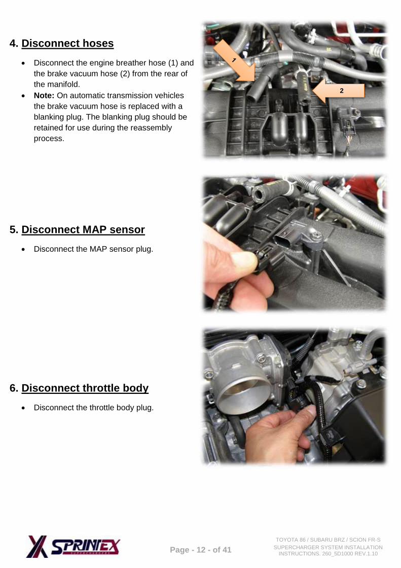
4. Disconnect hoses
Disconnect the engine breather hose (1) and
the brake vacuum hose (2) from the rear of
the manifold.
Note: On automatic transmission vehicles
the brake vacuum hose is replaced with a
blanking plug. The blanking plug should be
retained for use during the reassembly
process.
5. Disconnect MAP sensor
Disconnect the MAP sensor plug.
6. Disconnect throttle body
Disconnect the throttle body plug.
2
Page - 13 - of 41
TOYOTA 86 / SUBARU BRZ / SCION FR-S
SUPERCHARGER SYSTEM INSTALLATION INSTRUCTIONS. 260_5D1000 REV.1.10
7. Disconnect harness from manifold
Disconnect the wiring harness from the manifold supports.
Disconnect the alternator harness from the manifold covers.
8. Remove Injector covers
Disconnect the ECU from the injector cover (x3 screws) and carefully lower the ECU.
Remove the injector covers from the engine (x2 screws) from both left and right cylinder heads. .
9. Disconnect fuel rail support
Disconnect the EVAP solenoid hose from barb
(A).
Remove the screw from fuel rail support (B).
A
B
Page - 14 - of 41
TOYOTA 86 / SUBARU BRZ / SCION FR-S
SUPERCHARGER SYSTEM INSTALLATION INSTRUCTIONS. 260_5D1000 REV.1.10
10. Disconnect injector harness
Disconnect the injector plugs from the injectors. Disconnect the injector harness from the fuel rail on
both sides of the engine.
Disconnect fuel lines from the fuel rails on both sides of the engine.
Disconnect the EVAP solenoid connector and harness from the manifold (left hand side rear).
Page - 15 - of 41
TOYOTA 86 / SUBARU BRZ / SCION FR-S
SUPERCHARGER SYSTEM INSTALLATION INSTRUCTIONS. 260_5D1000 REV.1.10
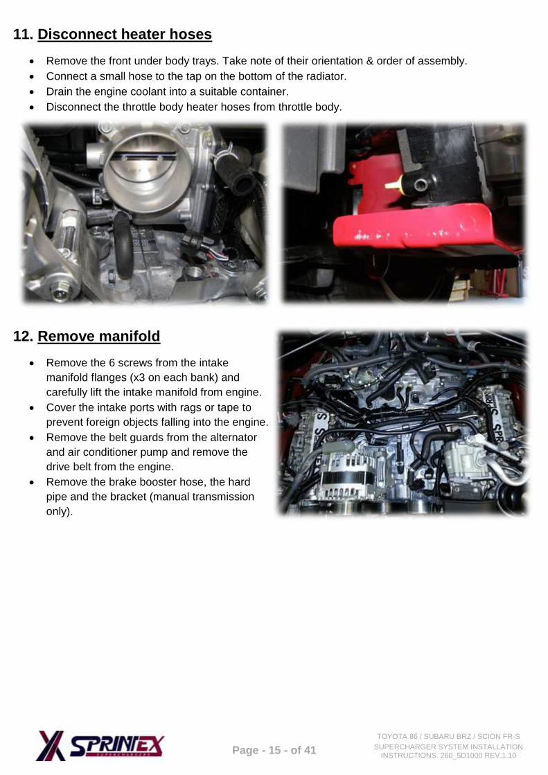
11. Disconnect heater hoses
Remove the front under body trays. Take note of their orientation & order of assembly.
Connect a small hose to the tap on the bottom of the radiator.
Drain the engine coolant into a suitable container.
Disconnect the throttle body heater hoses from throttle body.
12. Remove manifold
Remove the 6 screws from the intake
manifold flanges (x3 on each bank) and
carefully lift the intake manifold from engine.
Cover the intake ports with rags or tape to
prevent foreign objects falling into the engine.
Remove the belt guards from the alternator
and air conditioner pump and remove the
drive belt from the engine.
Remove the brake booster hose, the hard
pipe and the bracket (manual transmission
only).
Page - 16 - of 41
TOYOTA 86 / SUBARU BRZ / SCION FR-S
SUPERCHARGER SYSTEM INSTALLATION INSTRUCTIONS. 260_5D1000 REV.1.10
13. Remove the EVAP solenoid
Remove the EVAP solenoid from the manifold. Remove the throttle body and fuel rails from the
intake manifold. Ensure that the injector seals are removed from the manifold and set aside for
reinstallation to the supercharger system later.
Remove the 2 throttle body heater hoses from the engine. Remove the spring band clamps from the
original hoses. Put these aside to re-use later upon installation.
14. Remove the sound pipe
Remove the sound pipe from the engine bay.
Note that the hole in the firewall will need to
be blanked off.
From inside the cabin carefully pull down the
carpet in the right hand side foot-well to
expose the firewall hole where the sound
pipe was previously located.
Plug the hole with the grommet supplied in
the kit.
Page - 17 - of 41
TOYOTA 86 / SUBARU BRZ / SCION FR-S
SUPERCHARGER SYSTEM INSTALLATION INSTRUCTIONS. 260_5D1000 REV.1.10
16. Remove strut braces
Remove the 2 screws and 6 nuts that retain
the strut braces, remove the strut braces from
the vehicle and set aside.
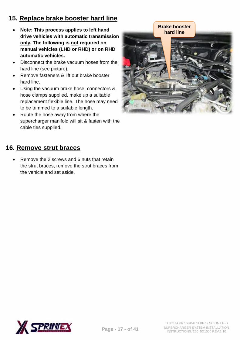
15. Replace brake booster hard line
Note: This process applies to left hand
drive vehicles with automatic transmission
only. The following is not required on
manual vehicles (LHD or RHD) or on RHD
automatic vehicles.
Disconnect the brake vacuum hoses from the
hard line (see picture).
Remove fasteners & lift out brake booster
hard line.
Using the vacuum brake hose, connectors &
hose clamps supplied, make up a suitable
replacement flexible line. The hose may need
to be trimmed to a suitable length.
Route the hose away from where the
supercharger manifold will sit & fasten with the
cable ties supplied.
Brake booster hard line
Page - 18 - of 41
TOYOTA 86 / SUBARU BRZ / SCION FR-S
SUPERCHARGER SYSTEM INSTALLATION INSTRUCTIONS. 260_5D1000 REV.1.10
TOYOTA 86 / SUBARU BRZ / SCION FR-S
SUPERCHARGER SYSTEM
SECTION 2
INSTALLATION INSTRUCTIONS
Page - 19 - of 41
TOYOTA 86 / SUBARU BRZ / SCION FR-S
SUPERCHARGER SYSTEM INSTALLATION INSTRUCTIONS. 260_5D1000 REV.1.10
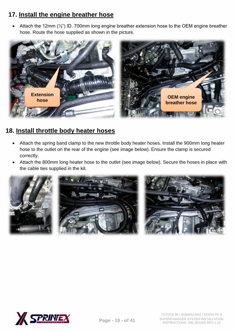
17. Install the engine breather hose
Attach the 12mm (½”) ID. 700mm long engine breather extension hose to the OEM engine breather
hose. Route the hose supplied as shown in the picture.
18. Install throttle body heater hoses
Attach the spring band clamp to the new throttle body heater hoses. Install the 900mm long heater
hose to the outlet on the rear of the engine (see image below). Ensure the clamp is secured
correctly.
Attach the 800mm long heater hose to the outlet (see image below). Secure the hoses in place with
the cable ties supplied in the kit.
Extension
hose OEM engine
breather hose
Page - 20 - of 41
TOYOTA 86 / SUBARU BRZ / SCION FR-S
SUPERCHARGER SYSTEM INSTALLATION INSTRUCTIONS. 260_5D1000 REV.1.10
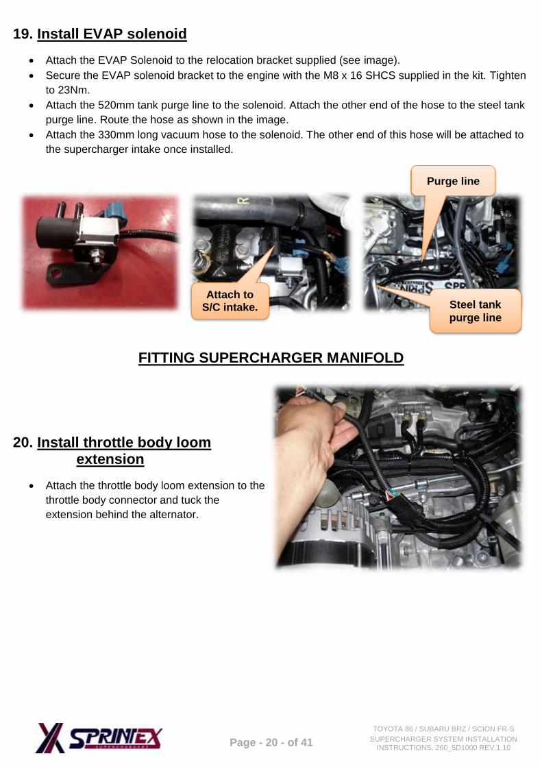
19. Install EVAP solenoid
Attach the EVAP Solenoid to the relocation bracket supplied (see image).
Secure the EVAP solenoid bracket to the engine with the M8 x 16 SHCS supplied in the kit. Tighten
to 23Nm.
Attach the 520mm tank purge line to the solenoid. Attach the other end of the hose to the steel tank
purge line. Route the hose as shown in the image.
Attach the 330mm long vacuum hose to the solenoid. The other end of this hose will be attached to
the supercharger intake once installed.
FITTING SUPERCHARGER MANIFOLD
20. Install throttle body loom extension
Attach the throttle body loom extension to the
throttle body connector and tuck the
extension behind the alternator.
Steel tank
purge line
Attach to S/C intake.
Purge line
Page - 21 - of 41
TOYOTA 86 / SUBARU BRZ / SCION FR-S
SUPERCHARGER SYSTEM INSTALLATION INSTRUCTIONS. 260_5D1000 REV.1.10
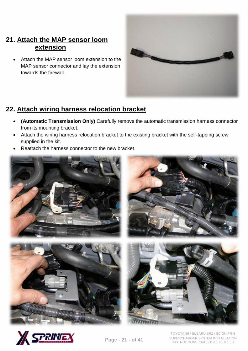
21. Attach the MAP sensor loom extension
Attach the MAP sensor loom extension to the
MAP sensor connector and lay the extension
towards the firewall.
22. Attach wiring harness relocation bracket
(Automatic Transmission Only) Carefully remove the automatic transmission harness connector
from its mounting bracket.
Attach the wiring harness relocation bracket to the existing bracket with the self-tapping screw
supplied in the kit.
Reattach the harness connector to the new bracket.
Page - 22 - of 41
TOYOTA 86 / SUBARU BRZ / SCION FR-S
SUPERCHARGER SYSTEM INSTALLATION INSTRUCTIONS. 260_5D1000 REV.1.10
INTERCOOLER SYSTEM INSTALLATION
23. Intercooler radiator installation (intercooled systems only steps 23-25)
Install the plastic elbow to the radiator as shown below. Apply thread sealant to the thread of the
elbow upon assembly.
Install the radiator support pins (x2).
Remove the screws that retain the air conditioner condenser. Also remove the screw that retains the
horn.
Fit the supplied Grommet (2x) to the top radiator brackets.
Install the radiator bracket onto the condenser mount bracket and retain with the OEM fasteners.
Repeat this process for the other side.
Fit the radiator by inserting the radiator support pins into the bracket grommets.
Fit the 2 bottom brackets & fix to the top brackets with the screws provided.
Reattach the horn in its original position.
Top
Bracket
Radiator
Support Pins
Elbow
Radiator Support Pin
Bottom
Bracket
Fit the
Grommet
Page - 23 - of 41
TOYOTA 86 / SUBARU BRZ / SCION FR-S
SUPERCHARGER SYSTEM INSTALLATION INSTRUCTIONS. 260_5D1000 REV.1.10
24. Water pump connection
Attach the water pump to the bracket with the
300mm heavy duty cable tie supplied in the
kit.
Attach the bracket, pump and loom to the
engine with the 2x M6 x 12 SHCS supplied
(see image). Tighten to 11Nm.
Page - 24 - of 41
TOYOTA 86 / SUBARU BRZ / SCION FR-S
SUPERCHARGER SYSTEM INSTALLATION INSTRUCTIONS. 260_5D1000 REV.1.10
25. Install the Intercooler hoses
Lay the intercooler return hose into the engine bay towards the firewall, attach the other end to the
top of the water pump.
Fit the hose to the pump outlet and route the other end of this hose down beside the vehicles
radiator. Fit the other end of the hose to the top hose connection of the radiator.
Lay the intercooler inlet hose into the engine bay towards the air conditioner pump. Route the other
end of the hose down alongside the washer bottle between the inner guard and outer panel. Feed
the hose through and connect the hose to the bottom radiator fitting.
Connect the 10mm (3/8”) x 1200mm long radiator hose to the plastic elbow on the radiator. Feed
the hose into the gap beside the vehicle’s radiator. Route the hose towards the firewall.
Tighten all the hose connections with the hose clamps supplied.
Intercooler
inlet hose
Intercooler
return hose
Hose connects to the water pump outlet and
top radiator inlet
Page - 25 - of 41
TOYOTA 86 / SUBARU BRZ / SCION FR-S
SUPERCHARGER SYSTEM INSTALLATION INSTRUCTIONS. 260_5D1000 REV.1.10
Cut out a 35mm wide x 40mm high hole in the RHS plastic panel next to the air conditioner
condensor. This will allow the bottom radiator hose to pass through when the radiator is installed.
Page - 26 - of 41
TOYOTA 86 / SUBARU BRZ / SCION FR-S
SUPERCHARGER SYSTEM INSTALLATION INSTRUCTIONS. 260_5D1000 REV.1.10
26. Install idler pulley
NOTE: Systems equipped with a Ø80mm or larger supercharger drive pulley require the Ø60mm
idler pulley to be fitted without a bearing shim. Systems equipped with a Ø75mm or smaller
supercharger drive pulley require the Ø70mm idler pulley to be fitted. If a Ø70mm idler pulley is to
be fitted, it requires the supplied bearing shim to be installed on the pulley mount behind the
bearing.
Remove the bolt from the alternator mount.
Attach the supplied idler pulley mount, idler pulley, M8 x 170 Hex. head bolt and retaining washer to
the alternator. Tighten to 23Nm.
27. Install vacuum fittings
Note that this step is only required if fitting a FT86 335+ system.
Prior to installing the manifold, fit the vacuum fittings supplied into the supercharger intake manifold. Please take note of the fittings orientation when installing.
Apply thread sealant to brass fitting prior to installation.
Remove bolt
8mm barb
½” barb
10mm barb
Page - 27 - of 41
TOYOTA 86 / SUBARU BRZ / SCION FR-S
SUPERCHARGER SYSTEM INSTALLATION INSTRUCTIONS. 260_5D1000 REV.1.10
28. Install fuel rails
Install the injector seals, injectors and fuel
rails onto the supercharger manifold. Prior to
installing the seals into the supercharger
manifold, apply rubber grease to the seals to
prevent damaging the seals upon assembly.
Turn the supercharger manifold upside down
onto a clean rag, to prevent marking the
supercharger. Install the manifold seals
supplied. Apply rubber grease to the O-rings
prior to assembly.
Turn the supercharger back over.
Install the throttle body seal and throttle body
onto the supercharger manifold. Attach the
throttle body with the OEM fasteners and
tighten to 12 Nm.
Note: This step only required on systems with
a S5-210 supercharger.
Attach the supercharger intake vacuum hose
to the vacuum actuator.
Page - 28 - of 41
TOYOTA 86 / SUBARU BRZ / SCION FR-S
SUPERCHARGER SYSTEM INSTALLATION INSTRUCTIONS. 260_5D1000 REV.1.10
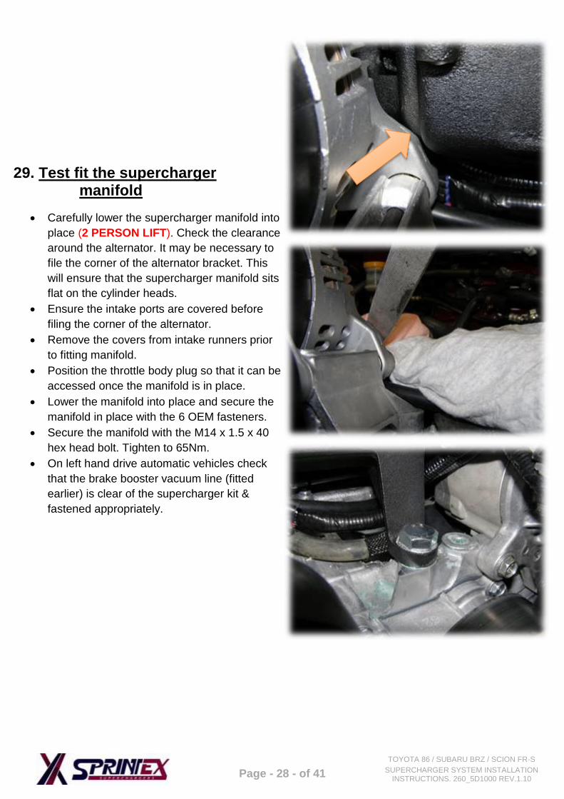
29. Test fit the supercharger manifold
Carefully lower the supercharger manifold into
place (2 PERSON LIFT). Check the clearance
around the alternator. It may be necessary to
file the corner of the alternator bracket. This
will ensure that the supercharger manifold sits
flat on the cylinder heads.
Ensure the intake ports are covered before
filing the corner of the alternator.
Remove the covers from intake runners prior
to fitting manifold.
Position the throttle body plug so that it can be
accessed once the manifold is in place.
Lower the manifold into place and secure the
manifold in place with the 6 OEM fasteners.
Secure the manifold with the M14 x 1.5 x 40
hex head bolt. Tighten to 65Nm.
On left hand drive automatic vehicles check
that the brake booster vacuum line (fitted
earlier) is clear of the supercharger kit &
fastened appropriately.
Page - 29 - of 41
TOYOTA 86 / SUBARU BRZ / SCION FR-S
SUPERCHARGER SYSTEM INSTALLATION INSTRUCTIONS. 260_5D1000 REV.1.10
30. Attach throttle body connector
Connect the electrical connector to the
throttle body.
31. Install supercharger pulley
Note: skip this step if fitting a FT86 335+
system as this system comes with the pulley
pre-fitted.
Install the supplied pulley to the pulley mount
on the supercharger, using the four M6 x 20
SHCS and flat washers supplied. Tighten to
12Nm.
32. Attach heater hoses
Connect the throttle body heater hoses to the
throttle body. Ensure the hose clamps are
installed correctly.
Page - 30 - of 41
TOYOTA 86 / SUBARU BRZ / SCION FR-S
SUPERCHARGER SYSTEM INSTALLATION INSTRUCTIONS. 260_5D1000 REV.1.10
33. Install drive belt
Use a 14 mm spanner to relieve the tension
on the dynamic tensioner and install new drive
belt. Follow the belt routing diagram (right)
and ensure that the belt is properly installed
on each pulley.
Reinstall the belt guards on the alternator and
air conditioner pump.
34. Connect fuel supply line
Reconnect the fuel supply lines on both sides of the engine. Ensure that the locking tab is fully
depressed.
Reconnect the injector harness on both sides of the engines.
Connect the water pump loom via the adaptor connectors to one of the fuel injector connectors.
Install the ECU mount and secure with the OEM fasteners. Attach the RHS injector cover and
secure with the OEM fasteners.
Reattach the ECU and secure with the OEM screws.
Attach the fuel rail support bracket.
Page - 31 - of 41
TOYOTA 86 / SUBARU BRZ / SCION FR-S
SUPERCHARGER SYSTEM INSTALLATION INSTRUCTIONS. 260_5D1000 REV.1.10
35. Attach MAP sensor connector
Attach the MAP sensor extension loom to the MAP sensor.
Page - 32 - of 41
TOYOTA 86 / SUBARU BRZ / SCION FR-S
SUPERCHARGER SYSTEM INSTALLATION INSTRUCTIONS. 260_5D1000 REV.1.10
ATTACH THE INTERCOOLER HOSES
36. Connect intercooler hoses
Non- intercooled systems skip this step.
Connect the hoses to the intercooler fittings.
Secure with the hose clamps supplied. Connect the overflow bottle to the intercooler
outlet hose. Secure with the hose clamps
supplied. Connect the 10mm (3/8”) hose to the spigot
of the overflow bottle. Secure with a hose
clamp. Fill the intercooler system via the overflow
bottle with 2200ml (74.4 fluid oz.) of ethylene
glycol based automotive engine coolant
approved for use in aluminium engines.
Temporarily connect the battery, turn the
ignition to the run position but do not start the
engine and confirm that the intercooler water
pump is running. With the pump running
continue to fill the system until all of the
2200ml of coolant is used. This step is
important as the intercooler will perform
poorly and restrict the engines performance if
air remains in the system. It may be
necessary to drive the vehicle or ‘work’ the
hoses to eliminate all the air from the system.
Check all intercooler hose connections for
leaks. Once the pump has been tested, disconnect
the battery again. Reinstall the under body trays.
Intercooler
return hose
Intercooler
inlet hose
Hose connects to the water pump outlet and
top radiator inlet
Page - 33 - of 41
TOYOTA 86 / SUBARU BRZ / SCION FR-S
SUPERCHARGER SYSTEM INSTALLATION INSTRUCTIONS. 260_5D1000 REV.1.10
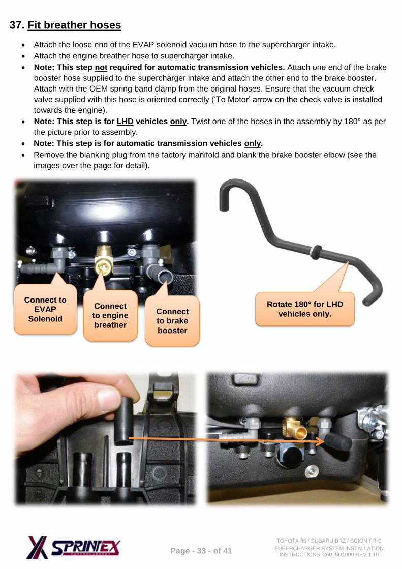
37. Fit breather hoses
Attach the loose end of the EVAP solenoid vacuum hose to the supercharger intake.
Attach the engine breather hose to supercharger intake.
Note: This step not required for automatic transmission vehicles. Attach one end of the brake
booster hose supplied to the supercharger intake and attach the other end to the brake booster.
Attach with the OEM spring band clamp from the original hoses. Ensure that the vacuum check
valve supplied with this hose is oriented correctly (‘To Motor’ arrow on the check valve is installed
towards the engine).
Note: This step is for LHD vehicles only. Twist one of the hoses in the assembly by 180° as per
the picture prior to assembly.
Note: This step is for automatic transmission vehicles only.
Remove the blanking plug from the factory manifold and blank the brake booster elbow (see the
images over the page for detail).
Connect to EVAP
Solenoid
Connect to engine
breather
Connect to brake
booster
Rotate 180° for LHD
vehicles only.
Page - 34 - of 41
TOYOTA 86 / SUBARU BRZ / SCION FR-S
SUPERCHARGER SYSTEM INSTALLATION INSTRUCTIONS. 260_5D1000 REV.1.10
38. Fit the inlet pipe
Attach the inlet pipe to the throttle body and
the air box with the silicon couplers and hose
clamps supplied. Connect the engine breather extension hose
to the inlet pipe.
Reinstall the strut braces.
39. Modify bonnet (hood) insulation
The under bonnet (hood) insulation must be removed or modified to prevent the supercharger drive
pulley contacting the insulation during some operating conditions.
Make a card board or paper template 100mm x 125mm.
Place a piece of double sided tape onto the centre of the template.
Lay the template onto the supercharger pulley with the tape side up make sure that the template is
central to the pulley.
Close the bonnet.
Lift the bonnet. The template should be attached to the bonnet lining. Mark out around the template
and cut out a section of the bonnet insulation. The cut edges should be covered with pinch weld or
fabric tape (not included) to prevent the edges fraying.
Note: Sprintex recommends simply removing the under bonnet insulation, as this allows it to be refitted unmodified at a later date if required.
Page - 35 - of 41
TOYOTA 86 / SUBARU BRZ / SCION FR-S
SUPERCHARGER SYSTEM INSTALLATION INSTRUCTIONS. 260_5D1000 REV.1.10
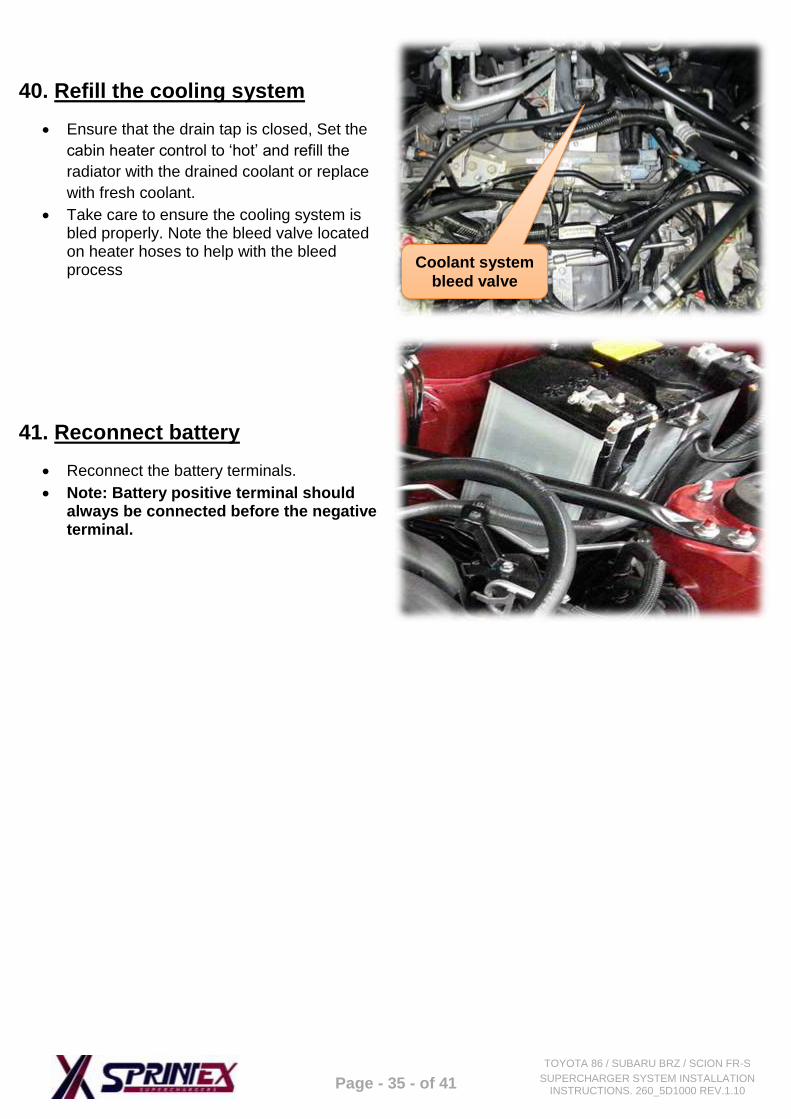
40. Refill the cooling system
Ensure that the drain tap is closed, Set the
cabin heater control to ‘hot’ and refill the
radiator with the drained coolant or replace
with fresh coolant.
Take care to ensure the cooling system is bled properly. Note the bleed valve located on heater hoses to help with the bleed process
41. Reconnect battery
Reconnect the battery terminals.
Note: Battery positive terminal should always be connected before the negative terminal.
Coolant system
bleed valve
Page - 36 - of 41
TOYOTA 86 / SUBARU BRZ / SCION FR-S
SUPERCHARGER SYSTEM INSTALLATION INSTRUCTIONS. 260_5D1000 REV.1.10
Page - 37 - of 41
TOYOTA 86 / SUBARU BRZ / SCION FR-S
SUPERCHARGER SYSTEM INSTALLATION INSTRUCTIONS. 260_5D1000 REV.1.10
TOYOTA 86 / SUBARU BRZ / SCION FR-S
SUPERCHARGER SYSTEM
SECTION 3
PRE TEST-DRIVE INSPECTION
Page - 38 - of 41
TOYOTA 86 / SUBARU BRZ / SCION FR-S
SUPERCHARGER SYSTEM INSTALLATION INSTRUCTIONS. 260_5D1000 REV.1.10
42. Pre-start inspection
Ensure the coolant is at the correct level.
Ensure the engine oil is at the correct level.
Ensure the vehicle has fresh 98 RON (91 Pump Octane USA) premium unleaded fuel or higher.
Ensure the belt is aligned.
Ensure the air filter is clean.
Check & replace spark plugs if necessary. Set the gaps to factory spec.
SAFETY WARNING: Ensure adequate steps are taken to prevent injury, spillage or fire should any of the
required installation steps not have been carried out to specification.
43. Engine warm up
Start the engine and allow it to run until it reaches normal operating temperature.
Check for leaks.
(Intercooled systems only) Check the intercooler overflow bottle coolant level with the engine
running and top up the system with the remainder of the 2200 ml of coolant. If the system does not
take the full 2200 ml of coolant there must be an air lock in the system. Top up the system once the
vehicle has been taken for a test drive.
Check the engine coolant level.
44. Road test vehicle
Road test vehicle.
Recheck all joints and connections for leaks –rectify as needed.
(Intercooled systems only) Check intercooler system coolant level.
Page - 39 - of 41
TOYOTA 86 / SUBARU BRZ / SCION FR-S
SUPERCHARGER SYSTEM INSTALLATION INSTRUCTIONS. 260_5D1000 REV.1.10
TOYOTA 86 / SUBARU BRZ / SCION FR-S
SUPERCHARGER SYSTEM
SECTION 4
MAINTENANCE INSTRUCTIONS
Page - 40 - of 41
TOYOTA 86 / SUBARU BRZ / SCION FR-S
SUPERCHARGER SYSTEM INSTALLATION INSTRUCTIONS. 260_5D1000 REV.1.10
45. Supercharger drive belt replacement
It is recommended that the supercharger drive belt be checked at every regular service and is
replaced at 50,000 km (30,000 miles) or 2 years, whichever occurs first.
Follow the routing diagram detailed below.
Use a 14mm wrench to
release the dynamic tensioner
to remove & replace the belt.
Dynamic tensioner
Page - 41 - of 41
TOYOTA 86 / SUBARU BRZ / SCION FR-S
SUPERCHARGER SYSTEM INSTALLATION INSTRUCTIONS. 260_5D1000 REV.1.10
46. Supercharger gearbox oil change interval
Drain and replace the supercharger oil every
50,000 km or 30,000 miles. Use Redline
75W90 NS gear oil or an equivalent spec.
lubricant.
It is critical not to overfill the supercharger
gearbox as damage will occur. Fill with
exactly 157 millilitres or 5.31 US fluid
ounces.
Ensure the vehicle is parked on level ground
before checking the oil level. Check the oil
level with the dipstick provided in the
supercharger assembly. Tighten the dipstick
fully before checking the oil level.
47. Supercharger gearbox oil change procedure
Ensure the vehicle is parked on level ground
before checking the oil level.
Remove the dipstick from the gearbox.
Using a syringe and a 120mm long piece of
tube draw out at much oil as possible from
the gearbox.
Fill the gearbox with Redline 75W90 NS gear
oil or an equivalent lubricant.
Check the oil level with the dipstick.
Refit the dipstick and tighten to 10Nm.
Note that an oil level sight glass is provided
for easy regular oil level checks. It is
recommended that the oil is checked every
day. Oil should be visible through the sight
glass.
Document No. 260_5D1000
Title. Toyota 86 / Subaru BRZ / Scion FR-S supercharger system installation instructions.