WARNINGEngine exhaust from this product containschemicals known, in certain quantities, to causecancer, birth defects, or other reproductive harm.
Thank you for purchasing this quality-built Ferris product. We’re pleasedthat you’ve placed your confidence in the Ferris brand. When operated andmaintained according to the instructions in this manual, your Ferris product willprovide many years of dependable service.
This manual contains safety information to make you aware of the haz-ards and risks associated with this machine and how to avoid them. Thismachine is designed and intended to be used and maintained according to themanual and operated by trained professionals for finish cutting of establishedlawns and is not intended for any other purpose. It is important that you readand understand these instructions thoroughly before attempting to start or oper-ate this equipment
The Ferris logo is a trademark of Briggs & StrattonCorporation Milwaukee, WI, USA.
Contact Information:Briggs & Stratton Yard Power Products Group5375 N. Main St.Munnsville, NY 13409-4003(800) 933-6175www.ferrisindustries.com
ENGINE REFERENCE DATA
Unit Model Number
PRODUCT REFERENCE DATA
Unit SERIAL Number
Dealer Name Date Purchased
Engine Make Engine Model
Mower Deck Model Number Mower Deck SERIAL Number
Engine Type/Spec. Engine Code/Serial Number
DATE PURCHASED
See Page 11 for the location of Identification Numbers
Table of ContentsOperator Safety ...................................................2
Identification Numbers ..........................................11Safety Decals ........................................................12Safety Interlock System ........................................13
Features & Controls ..........................................14Control Functions..................................................14
Operation ...........................................................16General .................................................................16Checks Before Starting .........................................16Starting the Engine ...............................................17Stopping the Rider ................................................17Pushing the Rider by Hand...................................17Zero Turn Driving Practice ....................................18Mowing..................................................................20Mowing Reccomendations....................................20Mowing Methods...................................................21Attaching a Trailer .................................................22Storage..................................................................23Starting After Long Term Storage .........................23
Troubleshooting, Adjustments & Service .......29Troubleshooting the Rider .....................................29Troubleshooting the Mower...................................30Troubleshooting Common Cutting Problems ........31Seat Adjustment....................................................32Ground Speed Control Lever Adjustment .............32Speed Balancing Adjustment................................32Parking Brake Adjustment ....................................33Rear Suspension Adjustment ...............................34Return to Neutral Adjustment ...............................35Neutral Adjustment ...............................................36Mowing Height Adjustment ...................................36Deck Leveling Adjustment.....................................37Hydraulic Pump Drive Belt Replacement..............38Mower Belt Replacement......................................39Battery Service .....................................................40
NOTE: In this manual, “left” and “right” are referred to asseen from the operating position.
1
SafetyControls
OperationM
aintenanceTroubleshooting
Specifications
2 www.ferrisindustries.com
Safe
tyOperator Safety
Operating SafetyCongratulations on purchasing a superior-quality piece of lawnand garden equipment. Our products are designed andmanufactured to meet or exceed all industry standards for safety.
Do not operate this machine unless you have been trained.Reading and understanding this operator’s manual is a way totrain yourself.
Power equipment is only as safe as the operator. If it is misused,or not properly maintained, it can be dangerous! Remember, youare responsible for your safety and that of those around you.
Use common sense, and think through what you are doing. Ifyou are not sure that the task you are about to perform can besafely done with the equipment you have chosen, ask a professional: contact your local authorized dealer.
Read the ManualThe operator’s manual contains important safetyinformation you need to be aware of BEFORE youoperate your unit as well as DURING operation.
Safe operating techniques, an explanation of theproduct’s features and controls, and maintenanceinformation is included to help you get the most out ofyour equipment investment.
Be sure to completely read the Safety Rules andInformation found on the following pages. Alsocompletely read the Operation section.
ChildrenTragic accidents can occur with children. Donot allow them anywhere near the area ofoperation. Children are often attracted to theunit and mowing activity. Never assume thatchildren will remain where you last saw them.If there is a risk that children may enter thearea where you are mowing, have anotherresponsible adult watch them.
3
SafetyOperator Safety
Slope OperationOperation on slopes can be dangerous. Using the unit on a slopethat is too steep where you do not have adequate wheel traction(and control) can cause sliding, loss of steering, control, andpossible rollover. You should not operate on a slope greater than a5.4 foot rise over a 20 foot length (15 degrees).
Always mow across slopes, not up and down (to maintain tractionon the wheels) and avoid sudden turns or rapid speed changes.Reduce speed and use extreme caution on ALL slopes.
Also, note that the surface condition you are on can greatly impactyour ability to safely operate this machine. Operating on wet orslippery slopes can cause sliding and loss of steering and control.Do not operate on slopes that are slippery, wet, or have soft soilconditions.
If you feel unsure about operating the unit on a slope, don’t do it.It’s not worth the risk.
Thrown ObjectsThis unit has spinning mower blades. These blades can pick up andthrow debris that could seriously injure a bystander. Be sure to cleanup the area to be mowed and remove objects that could be thrown bythe blade BEFORE you start mowing.
Do not operate this unit without the entire grass catcher or dischargeguard (deflector) in place.
Also, do not allow anyone in the area while the unit is running! Ifsomeone does enter the area, shut the unit off immediately until theyleave.
Moving PartsThis equipment has many moving parts that can injureyou or someone else. However, if you stay in the operatorzone (stay seated in the seat), and follow the safety rulesin this operator’s manual, the unit is safe to operate.
The mower deck has spinning mower blades that canamputate hands and feet. Do not allow anyone near theunit while it is running! Keep safety devices (guards,shields, and switches) in place and working.
To help you, the operator, use this equipment safely, it isequipped with an operator-present safety system. Do NOTattempt to alter or bypass the system. See your dealerimmediately if the system does not pass all the safetyinterlock system tests found in this manual.
4 www.ferrisindustries.com
Safe
ty
Roll Bar UseKeep the roll bar in the raised position and fasten theseat belt. There is no roll over protection when theroll bar is down! Do not jump off if the mower tips (it issafer to be secured by the seat belt with the roll barraised.)
Lower the roll bar only when necessary (such as totemporarily clear a low overhanging obstacle) andNEVER remove it. Do NOT use the seat belt whenthe roll bar is down. Raise the roll bar as soon asclearance permits.
Retaining Walls, Drop-offs, and Water
Retaining walls and drop-offs around steps andwater are a common hazard. Give yourself aminimum of two mower widths of clearancearound these hazards and hand-trim with a walkbehind mower or string trimmer. Wheelsdropping over retaining walls, edges, ditches,embankments, or into water can cause rollovers,which may result in serious injury, death, ordrowning.
Overhead ObstaclesCheck for overhead clearances before drivingunder any objects. Do not allow the roll bar tocontact low overhanging obstacles such as treebranches and guide wires.
Operator Safety
5
SafetyOperator Safety
Enclosed AreasOnly operate this unit outdoors andaway from unventilated areas such asinside garages or enclosed trailers. Theengine emits poisonous carbonmonoxide gas and prolonged exposurein an enclosed area can result inserious injury or death.
Fuel and MaintenanceAlways disengage all drives, shutoff the engine, andremove the key before doing any cleaning, refueling, orservicing.
Gasoline and its vapors are extremely flammable. Do notsmoke while operating or refueling. Do not add fuel whileengine is hot or running. Allow engine to cool for at least3 minutes prior to adding fuel.
Do not add fuel indoors, in an enclosed trailer, garage, orany other enclosed area that is not well ventilated.Gasoline spills should be cleaned up promptly and beforeoperation begins.
Gasoline should be stored only in sealed containersapproved for fuel.
Proper maintenance is critical to the safety andperformance of your unit. Keep the unit free of grass,leaves, and excess oil. Be sure to perform themaintenance procedures listed in this manual, especiallyperiodically testing the safety system.
6 www.ferrisindustries.com
Safe
ty
2. Mow only in the daylight or with good artificiallight, keeping away from holes and hiddenhazards.
3. Be sure all drives are in neutral and parking brakeis engaged before starting engine. Only startengine from the operator’s position. Use seatbelts if provided.
4. Be sure of your footing while using pedestriancontrolled equipment, especially when backing up.Walk, don’t run. Reduced footing could causeslipping.
5. Slow down and use extra care on hillsides. Besure to travel in the recommended direction onhillsides. Turf conditions can affect the machinesstability. Use caution when operating near drop-offs.
6. Do not mow in reverse unless absolutelynecessary. Always look down and behind beforeand while traveling in reverse.
7. Be aware of the mower discharge direction and donot point it at anyone. Do not operate the mowerwithout either the entire grass catcher or thedeflector in place.
8. Slow down and use caution when making turnsand when changing directions on slopes.
9. Never raise deck with the blades running.10. Never leave a running unit unattended. Always
disengage the PTO, set parking brake, stopengine, and remove keys before dismounting.Keep hands and feet away from the cutting units.
11. Turn off the PTO switch to disengage the bladeswhen not mowing.
12. Never operate with guards not securely in place.Be sure all interlocks are attached, adjustedproperly and functioning properly.
13. Never operate with the discharge deflector raised,removed or altered, unless using a grass catcher.
14. Do not change the engine governor setting oroverspeed the engine.
15. Stop on level ground, lower implements,disengage drives, engage parking brake, shut offengine before leaving the operator’s position forany reason including emptying the grass catchersor unclogging the chute.
16. Stop equipment and inspect blades after strikingobjects or abnormal vibration occurs. Makenecessary repairs before resuming operations.
17. Keep hands and feet away from the cutting units.18. Look behind and down before backing up to be
sure of a clear path.19. Never carry passengers and keep pets and
bystanders away.20. Do not operate the unit while under the influence
of alcohol or drugs.21. Slow down and use caution when making turns
and crossing roads and sidewalks. Stop blades ifnot mowing.
22. Use care when loading or unloading the machineinto a trailer or truck.
TRAINING1. Read, understand, and follow all instructions in the
manual and on the unit before starting. If theoperator(s) or mechanic(s) can not read English itis the owner’s responsibility to explain this materialto them.
2. Become familiar with the safe operation of theequipment, operator controls, and safety signs.
3. All operators and mechanics should be trained.The owner is responsible for training the users.
4. Only allow responsible adults, who are familiarwith the instructions, to operate the unit.
5. Never let children or untrained people operate orservice the equipment. Local regulations mayrestrict the age of the operator.
6. The owner/user can prevent and is responsible foraccidents or injuries occurring to themselves,other people or property.
7. Data indicates that operators, age 60 years andabove, are involved in a large percentage of ridingmower-related injuries. These operators shouldevaluate their ability to operate the riding mowersafely enough to protect themselves and othersfrom serious injury.
PREPARATION1. Evaluate the terrain to determine what
accessories and attachments are needed toproperly and safely perform the job. Use onlyaccessories and attachments approved by themanufacturer.
2. Wear appropriate clothing including safety shoes,safety glasses and ear protection. Long hair,loose clothing or jewelry may get tangled inmoving parts.
3. Inspect the area where the equipment is to beused and remove all objects such as rocks, toysand wire, which can be thrown by the machine.
4. Use extra care when handling gasoline and otherfuels. They are flammable and vapors areexplosive.a) Use only an approved container.
b) Never remove fuel cap or add fuel with theengine running. Allow engine to cool beforerefueling. Do not smoke.
c) Never refuel or drain the machine indoors.
5. Check that operator’s presence controls, safetyswitches and shields are attached and functioningproperly. Do not operate unless they arefunctioning properly.
OPERATION1. Never run an engine in an enclosed area.
Read these safety rules and follow them closely. Failure to obey these rules could result in loss ofcontrol of unit, severe personal injury or death to you, or bystanders, or damage to property orequipment. This mowing deck is capable of amputating hands and feet and throwing objects.The triangle in text signifies important cautions or warnings which must be followed.
Operator Safety
7
SafetyOperator Safety
23. Use care when approaching blind corners, shrubs,trees or other objects that may obscure vision.
24. To reduce fire hazard, keep unit free of grass,leaves & excess oil. Do not stop or park over dryleaves, grass or combustible materials.
25. The engine in this unit is not factory equipped witha spark arrester. It is a violation of CaliforniaPublic Resource Code Section 4442 to use oroperate the engine on or near any forest-covered,brush-covered, or grass-covered land unless theexhaust system is equipped with a spark arrestermeeting any applicable local or state laws. Otherstates or federal area may have similar laws.
26. OSHA regulations may require the use of hearingprotection when exposed to sound levels greaterthan 85 dBA for an 8 hour time period.
SLOPE OPERATIONSlopes are a major factor related to loss-of-control andtip-over accidents, which can result in severe injury ordeath. All slopes require extra caution. If you cannotback up the slope or if you feel uneasy on it, do notdrive on it.
Do1. Mow across slopes, not up and down.2. Remove obstacles such as rocks, tree limbs, etc.3. Watch for holes, ruts, or bumps. Uneven terrain
could overturn the unit. Tall grass can hideobstacles.
4. Use slow speed. Choose a slow speed so thatyou will not have to stop or change speed whileon the slope.
5. Use extra care with grass catchers or otherattachments. These can change the stability ofthe unit.
6. Keep all movement on the slopes slow andgradual. Do not make sudden changes in speedor direction.
7. See your authorized dealer for recommendationsof available weights to improve stability.
Do Not1. Avoid starting, stopping, or turning on a slope. If
tires lose traction (i.e. machine stops forwardmotion on a slope), disengage the blade(s) (PTO)and drive slow off the slope.
2. Do not turn on slopes unless necessary, and then,turn slowly and gradually uphill, if possible. Nevermow down slopes.
3. Do not mow near drop-offs, ditches, orembankments. The operator could lose footing orbalance or mower could suddenly turn over if awheel is over the edge of a cliff or ditch, or if anedge caves in.
4. Do not mow on wet grass. Reduced footing ortraction could cause sliding.
5. Do not try to stabilize the unit by putting your footon the ground. (ride-on units)
6. Do not mow excessively steep slopes.7. Do not use grass catcher on steep slopes.8. Do not mow slopes if you cannot back up them.
TOWED EQUIPMENT (RIDE-ON UNITS)1. Tow only with a machine that has a hitch designed
for towing. Do not attach towed equipment exceptat the hitch point.
2. Follow the manufacturer’s recommendations forweight limit for towed equipment and towing onslopes. See attaching a trailer under OPERATION.
3. Never allow children or others in or on towedequipment.
4. On slopes, the weight of the towed equipmentmay cause loss of traction and loss of control.
5. Travel slowly and allow extra distance to stop.6. Do not shift to neutral and coast down hill.
CHILDRENTragic accidents can occur if the operator is not alert tothe presence of children. Children are often attracted tothe unit and the mowing activity. Never assume thatchildren will remain where you last saw them.1. Keep children out of the mowing area and under
the watchful care of another responsible adult.2. Be alert and turn unit off if children enter the area.3. Before and during reverse operation, look behind
and down for small children.4. Never carry children, even with the blade(s) off.
They may fall off and be seriously injured orinterfere with safe unit operation. Children whohave been given rides in the past may suddenlyappear in the mowing area for another ride and berun over or backed over by the machine.
5. Never allow children to operate the unit.6. Use extra care when approaching blind corners,
shrubs, trees, or other objects that may obscurevision.
EMISSIONS1. Engine exhaust from this product contains
chemicals known, in certain quantities, to causecancer, birth defects, or other reproductive harm.
2. Look for the relevant Emissions Durability Periodand Air Index information on the engine emissionslabel.
CAUTIONThis machine produces sound levelsin excess of 85 dBA at the operator’sear and can cause hearing lossthough extended periods of exposure.
Wear hearing protection when operating thismachine.
WARNINGNever operate on slopes greater than 15degrees which is a rise of 5.4 feet (165 cm)vertically in 20 feet (607 cm) horizontally.Select slow ground speed before driving ontoslope. Use extra caution when operating onslopes with rear-mounted grass catchers.Mow across the face of slopes, not up anddown, use caution when changing directionsand DO NOT START OR STOP ON SLOPE.
8 www.ferrisindustries.com
Safe
tyOperator Safety
IGNITION SYSTEM (GASOLINE MODELS)1. This spark ignition system complies with Canadian
ICES-002.
SERVICE AND MAINTENANCETo avoid personal injury or property damage, useextreme care in handling gasoline. Gasoline isextremely flammable and the vapors are explosive.
Safe Handling of Gasoline1. Extinguish all cigarettes, cigars, pipes, and other
sources of ignition.2. Use only approved gasoline containers.3. Never remove the gas cap or add fuel with the
engine running. Allow the engine to cool beforerefueling.
4. Never fuel the machine indoors.5. Never store the machine or fuel container where
there is an open flame, spark, or pilot light suchas near a water heater or other appliance.
6. Never fill containers inside a vehicle or on a truckbed with a plastic bed liner. Always placecontainers on the ground away from your vehiclebefore filling.
7. Remove gas-powered equipment from the truck ortrailer and refuel it on the ground. If this is notpossible, then refuel such equipment on a trailerwith a portable container, rather than from agasoline dispenser nozzle.
8. Keep nozzle in contact with the rim of the fuel tankor container opening at all times until fueling iscomplete. Do not use a nozzle lock-open device.
9. If fuel is spilled on clothing, change clothingimmediately.
10. Never over-fill the fuel tank. Replace gas cap andtighten securely.
11. Use extra care in handling gasoline and otherfuels. They are flammable and vapors areexplosive.
12. If fuel is spilled, do not attempt to start the enginebut move the machine away from the area ofspillage and avoid creating any source of ignitionuntil fuel vapors have dissipated.
13. Replace all fuel tank caps and fuel container capssecurely.
Maintenance and Storage1. Always observe safe refueling and fuel handling
practices when refueling the unit aftertransportation or storage.
2. Always follow the engine manual instructions forstorage preparations before storing the unit forboth short and long term periods.
3. Always follow the engine manual instructions forproper start-up procedures when returning the unitto service.
4. Never store the machine or fuel container insidewhere there is an open flame, such as in a waterheater. Allow unit to cool before storing.
5. Shut off fuel while storing or transporting. Do notstore fuel near flames or drain indoors.
6. Keep all hardware, especially blade attachmentbolts, tight and keep all parts in good workingcondition. Replace all worn or damaged decals.
7. Never tamper with safety devices. Check theirproper operation regularly.
8. Disengage drives, lower implement, set parkingbrake, stop engine and remove key or disconnectspark plug wire. Wait for all movement to stopbefore adjusting, cleaning or repairing.
9. Clean grass and debris from cutting units, drives,mufflers, and engine to prevent fires. Clean up oilor fuel spillage.
10. Let engine cool before storing and do not storenear flame.
11. Stop and inspect the equipment if you strike anobject. Repair, if necessary, before restarting.
12. Park machine on level ground. Never allowuntrained personnel to service machine.
13. Use jack stands to support components whenrequired.
14. Carefully release pressure from components withstored energy.
15. Disconnect battery or remove spark plug wirebefore making any repairs. Disconnect thenegative terminal first and the positive last.Reconnect positive first and negative last.
16. Use care when checking blades. Wrap theblade(s) or wear gloves, and use caution whenservicing them. Only replace blades. Neverstraighten or weld them.
17. Keep hands and feet away from moving parts. Ifpossible, do not make adjustments with the enginerunning.
18. Charge batteries in an open well ventilated area,away from spark and flames. Unplug chargerbefore connecting or disconnecting from battery.Wear protective clothes and use insulated tools.
19. Grass catcher components are subject to wear,damage, and deterioration, which could exposemoving parts or allow objects to be thrown.Frequently check components and replace withmanufacturer’s recommended parts, whennecessary.
20. Check brake operation frequently. Adjust andservice as required.
21. Use only factory authorized replacement partswhen making repairs.
22. Always comply with factory specifications on allsettings and adjustments.
23. Only authorized service locations should beutilized for major service and repair requirements.
24. Never attempt to make major repairs on this unitunless you have been properly trained. Improperservice procedures can result in hazardousoperation, equipment damage and voiding ofmanufacturer’s warranty.
25. Units with hydraulic pumps, hoses, or motors:WARNING: Hydraulic fluid escaping underpressure may have sufficient force to penetrateskin and cause serious injury. If foreign fluid isinjected into the skin it must be surgically removedwithin a few hours by a doctor familiar with thisform of injury or gangrene may result. Keep bodyand hands away from pin holes or nozzles thateject hydraulic fluid under high pressure. Usepaper or cardboard, and not hands, to search forleaks. Make sure all hydraulic fluid connectionsare tight and all hydraulic hoses and lines are ingood condition before applying pressure to thesystem. If leaks occur, have the unit servicedimmediately by your authorized dealer.
26. WARNING: Stored energy device. Improperrelease of springs can result in serious personalinjury. Springs should be removed by anauthorized technician.
9
SafetyOperator Safety
27. Models equipped with an engine radiator:WARNING: Stored energy device. To preventserious bodily injury from hot coolant or steamblow-out, never attempt to remove the radiator capwhile the engine is running. Stop the engine andwait until it is cool. Even then, use extreme carewhen removing the cap.
ROLL BAR INSTRUCTIONSFor models equipped with factory-installed Roll OverProtection System (ROPS).
OPERATIONAL WARNINGS• Always use the seat belt when the roll bar is in the
raised position.• Never use the seat belt when the roll bar is in the
down position.• Remember there is no roll over protection when
the roll bar is in the down position so it is veryimportant to always keep the roll bar in the raisedposition whenever possible.
• Lower the roll bar to the down position only whenit is absolutely necessary.
• Check for overhead clearances before drivingunder any objects. Do not allow roll bar to contactlow overhanging obstacles such as tree branchesand guide wires.
• Never remove the roll bar from the vehicle.• Do not exceed the machine weight rating of the
roll bar.• Read and follow all of the instructions shown
below regarding the inspection and maintenanceof the roll bar structure and the seat belt.
INSPECTION OF THE ROLL BAR PROTECTIVESTRUCTUREA ROLL BAR, like any other safety device, needs to beperiodically inspected to verify that the integrity of thedevice has not been compromised through normalmachine use, misuse, age degradation, modifications,or a roll over.
To maintain operator roll over protection and roll bareffectiveness:
• If a ROLL BAR becomes damaged for any reason,such as a collision, roll over or impact, the ROLLBAR must be replaced. Small undetectablecracks can reduce the effectiveness of the ROLLBAR. Never weld, straighten, or repair the ROLLBAR.
WARNINGIn order to avoid serious injury or death fromroll over, it is important to follow the warningslisted below.
WARNINGFailure to properly inspect and maintain theROLL BAR protective structure can causeserious injury or death.
• Never alter the ROLL BAR by welding anything toit or by drilling additional holes.
• BEFORE FIRST TIME USE - Inspect the ROLLBAR structure and mounting hardware for:
1) Check to make sure the machine GVW (GrossVehicle Weight), including attachments,restrained payload, fuel and operator, is not inexcess of the maximum weight specified onthe ROLL BAR label.
2) Make sure there isn’t any missing, damaged,or loose mounting hardware.
3) Make sure the ROLL BAR has been correctlyand completely installed.
• EVERY 100 HOURS - Inspect the ROLL BARstructure and mounting hardware for:
1) Any cracks in the structure (structuralmembers and/or welds).
2) Significant corrosion on any part of the ROLLBAR structure or hardware.
3) Missing, damaged, or loose mountinghardware
4) Mounting hardware that is of a grade lesserthan specified.
5) Machine GVW (Gross Vehicle Weight),including attachments, restrained payload, fueland operator, in excess of the maximum weightspecified on the ROLL BAR label.
6) Any modifications that have been made, suchas unauthorized welds and holes.
7) Any permanent deformation or twisting of theROLL BAR structure.
8) That the ROLL BAR label is still in place and isreadable.
9) That the ROLL BAR on-product warning labelsare still on the ROLL BAR and are readable.
• If there is any doubt as to the condition of theROLL BAR, remove the machine from service andcontact your dealer for assistance.
10 www.ferrisindustries.com
Safe
ty
INSPECT BUCKLE& LATCH
INSPECT WEBBING
Operator Safety
WARNINGFailure to properly inspect and maintain theseat belt can cause serious injury or death.
INSPECTION AND MAINTENANCE OFTHE ROLL BAR SEAT BELT
• The seat belt like the ROLL BAR, needs to beperiodically inspected to verify that the integrityhas not been compromised through normalmachine use, misuse, age degradation,modifications, or a roll over. If the seat belt doesnot pass all of the following tests, it should bereplaced.
• BEFORE EACH USE – Conduct the followinginspections/maintenance of the seat belt andretraction mechanism:
1) Check for dirt or debris in the retractionmechanism. If dirt or debris is found, it shouldbe removed.
2) Check to make sure the retraction mechanismretracts easily and completely.
3) Check for damage to any part of the seat beltsuch as nicks, cuts, loose stitching, or fraying.
4) Check that the buckle and latch operateproperly and that the latch plate is notexcessively worn, deformed, or the buckle isdamaged or cracked. The seat belt shouldlatch and release easily.
SafetyOperator Safety
IDENTIFICATION NUMBERS
SSAAMMPPLLEE
When contacting your authorized dealer forreplacement parts, service, or information youMUST have these numbers.
Record your part number, serial number and engineserial numbers in the space provided for easy access.These numbers can be found in the locations shown.
NOTE: For location of engine identification numbers,refer to the engine owner’s manual.
IdentificationTag
11
12 www.ferrisindustries.com
Safe
ty
SAFETY DECALSThis unit has been designed and manufactured toprovide you with the safety and reliability you wouldexpect from an industry leader in outdoor powerequipment manufacturing.
Although reading this manual and the safetyinstructions it contains will provide you with thenecessary basic knowledge to operate this equipmentsafely and effectively, we have placed several safetylabels on the unit to remind you of this importantinformation while you are operating your unit.
All DANGER, WARNING, CAUTION andinstructional messages on your rider and mowershould be carefully read and obeyed. Personal bodilyinjury can result when these instructions are notfollowed. The information is for your safety and it isimportant! The safety decals below are on your riderand mower.
If any of these decals are lost or damaged, replacethem at once. See your local dealer for replacements.
These labels are easily applied and will act as aconstant visual reminder to you, and others who mayuse the equipment, to follow the safety instructionsnecessary for safe, effective operation.
Operator Safety
1
2
3
45
11
12
10
9
6
6
8
7
1
2
3
4
6
5
7
8
9
1110
12
13
SafetyOperator Safety
SAFETY INTERLOCKSYSTEM
This unit is equipped with safety interlock switches.These safety systems are present for your safety, donot attempt to bypass safety switches, and nevertamper with safety devices. Check their operationregularly.
Operational SAFETY Checks
Test 1 — Engine should NOT crank if:
• PTO switch is engaged, OR• Parking brake is not engaged, OR• Motion control handles are not in the NEUTRAL
position.
Test 2 — Engine SHOULD crank if:
• PTO switch is NOT engaged, AND• Parking brake is engaged, AND• Motion control handles are locked in the
NEUTRAL position.
Test 3 — Engine should SHUT OFF if:
• Operator rises off seat with PTO engaged, OR• Operator rises off seat with parking brake
disengaged.• Operator moves motion control handles out of
their neutral positions before disengaging parkingbrake.
Test 4 — Blade Brake Check
Mower blades and mower drive belt should come to acomplete stop within seven (7) seconds after electricPTO switch is turned off (or operator rises off seat).If mower drive belt does not stop within seven (7)seconds, see your dealer.
NOTE: Once the engine has stopped, PTO switchmust be turned off, parking brake must be engaged,and the motion control handles must be locked in theNEUTRAL position after the operator returns to theseat in order to start the engine.
WARNINGIf the unit does not pass a safety test, do notoperate it. See your authorized dealer. Underno circumstance should you attempt to defeatthe purpose of the safety interlock system.
SAFETY ICONSThe alert symbol is used to identity safetyinformation about hazards that can result in personalinjury. A signal word (DANGER, WARNING, orCAUTION) is used with the alert symbol to indicatethe likelihood and the potential severity of the injury.In addition, a hazard icon may be used to representthe type of hazard. An explanation of hazard levelsand icons are as follows:
DANGERThis indicates a hazard which, if not avoided, willresult in serious injury or death.
WARNINGThis indicates a hazard which, if not avoided, couldresult in serial injury or death.
CAUTIONThis indicates a hazard which, if not avoided, mightresult in minor or moderate injury.
CAUTION or NOTICEThese messages presented without the alert symbolindicate a situation where the unit or property couldbe damaged.
Hazard SafetyIcon
Alert
ToxicFumes
Read theManual
Open flamehazard
FireHazard
AmputationRotatingPartsAmputationHand inBlade
Hazard SafetyIcon
AmputationFoot inBlade
ThrownObjects
Maintain asafedistanceKeepchildrenaway
Hotsurface
WearProtectiveGear
PinchPoint
NORTH AMERICAN SAFETY ICONS
RolloverHazard
OverheadObstacles
14 www.ferrisindustries.com
Cont
rols
CONTROL FUNCTIONSThe information below briefly describes the function of individual controls. Starting, stopping, driving, andmowing require the combined use of several controls applied in specific sequences. To learn what combinationand sequence of controls to use for various tasks see the OPERATION section.
Ground Speed LeversThese levers control the ground speed of the rider.The left lever controls the left rear drive wheel and theright lever controls the right rear drive wheel.
Moving a lever forward increases the FORWARDspeed of the associated wheel, and pulling back on alever increases the REVERSE speed.
Note: The further a lever is moved away from theneutral position the faster the drive wheel will turn.
See the Operation section for proper steeringinstructions.
Seat Adjustment LeverThe seat can be adjusted forward and back. Move thelever towards the left, position the seat as desired,and release the lever to lock the seat in position.
Ignition Switch The ignition switch starts and stops the engine, it hasthree positions:
OFF Stops the engine and shuts off the
electrical system.
RUN Allows the engine to run and powers
the electrical system.
START Cranks the engine for starting.
NOTE: Never leave the ignition switch in the RUNposition with the engine stopped–this drains thebattery.
Figure 1. Control Locations
Features and Controls
Features and Controls
Fuel Tank CapTo remove the cap, turn counterclockwise.
Fuel Level GaugeDisplays the fuel level in the tank.
Features & Controls
15
Controls
Parking Brake
DISENGAGE Releases the parking brake.
ENGAGE Locks the parking brake.
Pull the parking brake lever back to engage theparking brake. Move the lever fully forward todisengage the parking brake. NOTE: To start the unitthe parking brake must be engaged.
PTO (Power Take Off) SwitchThe PTO switch engages and disengages the mower.Pull UP on the switch to engage, and push DOWN todisengage.
Deck Lift Pedal, CuttingHeight Adjustment Pin & Deck Lift LockLeverThese control the cutting height of the mower deck.Depress the pedal until it locks into the 4-1/2” (11,4cm) position. Place the adjustment pin in the desiredcutting height and release the lift lock lever.
Throttle ControlThe throttle controls engine speed. Move the throttleforward to increase engine speed and back todecrease engine speed. Always operate at FULLthrottle.
Choke Close the choke for cold starting. Open the chokeonce the engine starts. A warm engine may notrequire choking. Pull the knob UP to close the choke.Push to knob DOWN to open the choke.
Hour Meter / Maintenance ReminderMeasures the time of the PTO being engaged. Thehour meter measures the number of hours the PTOhas been engaged. The hour meter will flash aninitial oil change indicator at 5 hours, and a lubricationreminder every 50 hours. These reminders display forapproximately two hours and will automatically resetthemselves.Note: The hour meter will register the passage of timeonly when the PTO is engaged. The hour meter hasa self contained power source so the total hours arealways visible.
16 www.ferrisindustries.com
Oper
atio
n
GENERAL OPERATING SAFETYBefore first time operation:
• Be sure to read all information in the Safety andOperation sections before attempting to operatethis tractor and mower.
• Become familiar with all of the controls and how tostop the unit.
• Drive in an open area without mowing to becomeaccustomed to the unit.
CHECKS BEFORE STARTING• Check that crankcase is filled to full mark on
dipstick. See the engine Operator’s Manual forinstructions and oil recommendations.
• Make sure all nuts, bolts, screws and pins are inplace and tight.
• Adjust the seat position, and make certain youcan reach all controls from operator’s position.
• Fill the fuel tank with fresh fuel. Refer to enginemanual for fuel recommendations.
WARNINGNever allow passengers to ride on the unit.
Before leaving the operator’s position for anyreason, engage the parking brake, disengagethe PTO, stop the engine and remove the key.
To reduce fire hazard, keep the engine, tractorand mower free of grass, leaves and excessgrease. Do not stop or park tractor over dryleaves, grass or combustible materials.
Gasoline is highly flammable and must behandled with care. Never fill the tank when theengine is still hot from recent operation. Do notallow open flame, smoking or matches in thearea. Avoid over-filling and wipe up any spills.
Do not load this zero-turn rider on a trailer ortruck using two separate ramps. Only use asingle ramp that is at least one foot wider thanthe width of the rear wheels of this rider. Thisrider has a zero turning radius and the rearwheels could fall off the ramps, or the ridercould tip over injuring the operator orbystanders.
WARNINGNever operate on slopes greater than 17.6percent (10°) which is a rise of 3-1/2 feet (106cm) vertically in 20 feet (607 cm) horizontally.
Select slow ground speed before driving onto aslope. Use extra caution when operating onslopes with a rear-mounted grass catcher.
Mow across the face of slopes, not up anddown, use caution when changing directionsand DO NOT START OR STOP ON SLOPE.
WARNING
Operation
Operation
WARNINGIf you do not understand how a specific controlfunctions, or have not yet thoroughly read theFEATURES & CONTROLS section, do so now.
Do NOT attempt to operate the tractor withoutfirst becoming familiar with the location andfunction of ALL controls.
STARTING THE ENGINE1. While sitting in the operator’s seat, engage the
parking brake and make sure the PTO switch isdisengaged and the motion control handles arelocked in the NEUTRAL position.
2. NOTE: A warm engine may not requirechoking.Set the engine throttle control to FULL throttleposition. Then fully close the choke by pulling theknob OUT fully.
3. Insert the key into the ignition switch and turn it toSTART.
4. After the engine starts, gradually open the choke(push knob down fully). Reduce to half throttlespeed and allow the engine to warm.
Warm up the engine by running it for at least a minutebefore engaging the PTO switch or driving the rider.
5. After warming the engine, ALWAYS operate theunit at FULL THROTTLE when mowing.
In the event of an emergency the engine can bestopped by simply turning the ignition switch toSTOP. Use this method only in emergency situations.For normal engine shut down follow the proceduregiven in STOPPING THE RIDER.
STOPPING THE RIDER1. Returning the ground speed control levers to the
middle position will stop rider movement. Pivotthe levers outward and lock them in NEUTRAL.
2. Disengage the PTO by pushing down on the PTOswitch.
3. Engage the parking brake by pulling the handle upuntil it locks into position.
4. Move the throttle control to mid-throttle positionand turn the ignition key to OFF. Remove the key.
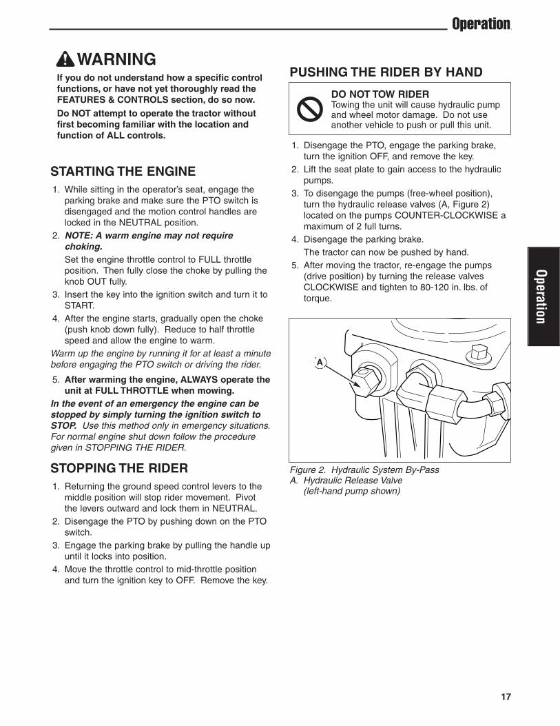
PUSHING THE RIDER BY HAND
1. Disengage the PTO, engage the parking brake,turn the ignition OFF, and remove the key.
2. Lift the seat plate to gain access to the hydraulicpumps.
3. To disengage the pumps (free-wheel position),turn the hydraulic release valves (A, Figure 2)located on the pumps COUNTER-CLOCKWISE amaximum of 2 full turns.
4. Disengage the parking brake.The tractor can now be pushed by hand.
5. After moving the tractor, re-engage the pumps(drive position) by turning the release valvesCLOCKWISE and tighten to 80-120 in. lbs. oftorque.
DO NOT TOW RIDERTowing the unit will cause hydraulic pumpand wheel motor damage. Do not useanother vehicle to push or pull this unit.
Operation
Figure 2. Hydraulic System By-PassA. Hydraulic Release Valve
(left-hand pump shown)
17
Operation
A
Operation
ZERO TURNDRIVING PRACTICEThe lever controls of the Zero Turn rider areresponsive, and learning to gain a smooth andefficient control of the rider’s forward, reverse, andturning movements will take some practice.
Spending some time going through the maneuversshown and becoming familiar with how the unitaccelerates, travels, and steers — before you beginmowing —is absolutely essential to getting the mostout of the Zero Turn rider.
Locate a smooth, flat area of your lawn — one withplenty of room to maneuver. (Clear the area ofobjects, people and animals before you begin.)Operate the unit at mid-throttle during this practicesession (ALWAYS operate at full throttle whenmowing), and turn slowly to prevent tire slippage anddamage to your lawn.
We suggest you begin with the Smooth Travelprocedure to the right, and then advance through theforward, reverse, and turning maneuvers.
You must release the parking brake prior to movingthe control levers inward.
BASIC DRIVING
Forward Travel PracticeGradually move both ground speed control levers —evenly FORWARD from neutral. Slow down andrepeat.
NOTE: Straight forward travel takes practice. Ifnecessary, top speed can be balance-adjusted — seethe Speed Balancing Adjustment in the Adjustmentssection near the back of this manual.
Reverse Travel PracticeLOOK DOWN & BEHIND, then gradually move bothground speed control levers evenly BACK fromneutral. Slow down and repeat.
NOTE: Practice backing up for several minutes beforeattempting to do so near objects. The rider turnssharply in reverse as well as forward, and backing upstraight takes practice.
Figure 4. Forward Travel
ForwardTravel
Figure 5. Reverse Travel
ReverseTravel
Smooth TravelThe lever controls ofthe Zero Turn rider areresponsive.
The BEST method ofhandling the groundspeed control levers isin three steps — asshown in Figure 3.
FIRST place yourhands onto the leversas shown.
SECOND, to goforward gradually pushthe levers forward withyour palms.
THIRD, to speed upmove the levers fartherforward. To slow downsmoothly, slowly movethe levers towardneutral.
Figure 3. Move ControlLevers Gradually
18 www.ferrisindustries.com
Oper
atio
n
ADVANCED DRIVING
Executing an End-Of-Row ZeroTurnYour Zero Turn Rider’s unique ability to turnin place allows you to turn around at theend of a cutting row rather than having tostop and Y-turn before starting a new row.
For example, to execute a left end-of rowzero turn:
1. Slow down at the end of the row.2. Move the RIGHT ground speed control
lever forward slightly while moving theLEFT ground speed control lever back tocenter and then slightly back fromcenter.
3. Begin mowing forward again.This technique turns the rider LEFT andslightly overlaps the row just cut —eliminating the need to back up and re-cutmissed grass.
As you become more familiar andexperienced with operating the Zero Turnrider, you will learn more maneuvers thatwill make your mowing time easier andmore enjoyable.
Remember, the more you practice, thebetter your control of the Zero Turn willbe!
Practice Turning Around a CornerWhile traveling forward allow one handle to graduallyreturn back toward neutral. Repeat several times.
NOTE: To prevent pivoting directly on the tire tread, itis best to keep both wheels going at least slightlyforward.
Figure 6. Turning Around a Corner Figure 7. Turning in Place
Figure 8. Executing an End-Of-Row Turn
19
Operation
Practice Turning In PlaceTo turn in place, “Zero Turn,” gradually move oneground speed control lever forward from neutral andone lever back from neutral simultaneously. Repeatseveral times.
NOTE: Changing the amount each lever is pulled—forward or back, changes the “pivot point” you turn on.
Operation
ExecutingTurns
TurningIn-Place
20 www.ferrisindustries.com
Oper
atio
n
MOWING1. Engage the parking brake. Make sure the PTO
switch is disengaged, the motion control levers arelocked in the NEUTRAL position and the operatoris on the seat.
2. Start the engine (see STARTING THE ENGINE).3. Set the mower cutting height.4. Set the throttle to FULL.5. Engage the PTO by pulling up on the PTO switch.6. Begin mowing. See Section LC for tips on
mowing patterns, lawn care, and trouble shootinginformation.
7. When finished, shut off the PTO.8. Stop the engine (see STOPPING THE TRACTOR
AND ENGINE).Tall Grass Requires Incremental CuttingFor extremely tall grass, set the cutting height atmaximum for the first pass, and then reset it to thedesired height and mow a second or third time.
Don’t cover the grass surface with a heavy layer ofclippings. Consider using a grass collection systemand starting a compost pile.
Figure 9. Proper Cutting Height
Figure 10. Incremental Cutting
CutHere OnSecondPass
Cut Here OnFirst Pass
MOWING RECOMMENDATIONSSeveral factors can affect how well your machine cutsgrass, Following proper mowing recommendationscan improve the performance and life of yourmachine.
Height of GrassOften cutting height is a matter of personalpreference. Typically, you should mow the grass whenit is is between three and five inches high. The propercutting height range for a specific lawn will dependupon several factors, including the type of grass, theamount of rainfall, the prevailing temperature, and thelawn’s overall condition.
Cutting the grass too short causes weak, thin grassplants, which are easily damaged by dry periods andpests. Cutting too short is often more damaging thanallowing the grass to be slightly higher.
Letting grass grow a bit longer—especially when it ishot and dry—reduces heat build-up, preservesneeded moisture and protects the grass from heatdamage and other problems. However, allowing grassto grow too high can cause thin turf and additionalproblems.
Cutting off too much at one time shocks the plant’sgrowth system and weakens the grass plants. A goodrule of thumb is the 1/3 rule: to cut no more thanone third of the grass height, and never more than1 inch at a time.
The amount of grass you are able to cut in one passis also effected by the type of mowing system you areusing (for example, broadcasting with side dischargedecks can process a much larger volume of grassthan mulching does).
Operation
21
Operation
When and How Often to MowThe time of day and condition of the grass greatlyaffect the results you’ll get when mowing. For the bestresults, follow these guidelines:1. Mow when the grass is between three and five
inches high.
2. Mow with sharp blades. Short clippings of grassone inch or shorter decompose more quickly thanlonger blades. Sharp mower blades cut grasscleanly and efficiently, preventing frayed edgeswhich harm the grass.
3. Mow at time of day when the grass is cool anddry. Late afternoon or early evening often providethese ideal mowing conditions.
4. Avoid mowing after rain or even heavy dew, andnever mulch when the grass is wet (moist grassdoes not mulch well, and clumps beneath themower deck).
Mowing PatternsAlways start mowing on a smooth, level area.
The size and type of area to be mowed will determinethe best mowing pattern to use. Obstructions such astrees, fences and buildings, and conditions such asslopes and grades must also be considered.1. Cut long straight strips overlapping slightly.
2. Where possible, change patterns occasionally toeliminate matting, graining or a corrugatedappearance.
3. For a truly professional cut, mow across the lawnin one direction, then recut the lawn by mowingperpendicular to the previous cut.
Note: Always operate the engine at full throttlewhen mowing.
If you hear the engine slowing down, you are mowingtoo fast—using a slower ground speed will improvethe cutting efficiency of the blades and prevents manycommon cutting problems. Use an appropriate groundspeed for the thickness and height of the grass youare cutting (3rd gear or slower for manual gearmodels). If you hear the engine slowing down you aremowing too fast, use a slower ground speed.
MOWING METHODS
Proper Broadcast MowingBroadcasting, or side-discharging, disperses fineclippings evenly over the entire lawn. Many golfcourses use this method. Your mower has a deep dishdeck to allow freer circulation of clippings so they arebroadcast evenly over the lawn.
ENGINE SPEED & GROUND SPEED FORBROADCASTING
Always operate the engine at full throttle whenmowing. If you hear the engine slowing down, youare mowing too fast—using a slower ground speedwill improve the cutting efficiency of the blades andprevents many common cutting problems.
ALWAYS use an appropriate ground speed for thethickness and height of the grass you are cutting (3rdgear or slower for manual gear models). If you hearthe engine slowing down you are mowing too fast,use a slower ground speed.
HOW MUCH GRASS TO CUT OFF WHENBROADCASTING
Mow when the grass is 3-5 inches long. Do not cutthe grass shorter than 2 to 2-1/2 inches. Do not cutoff more that 1 inch of grass in a single pass
Where possible, make one or two passes around theoutside of the area discharging the grass INTO thelawn to keep the cut grass off fences and walks.
The remainder of the mowing should be done in theopposite direction so that the clippings are dispersedOUT onto the area of lawn previously cut.
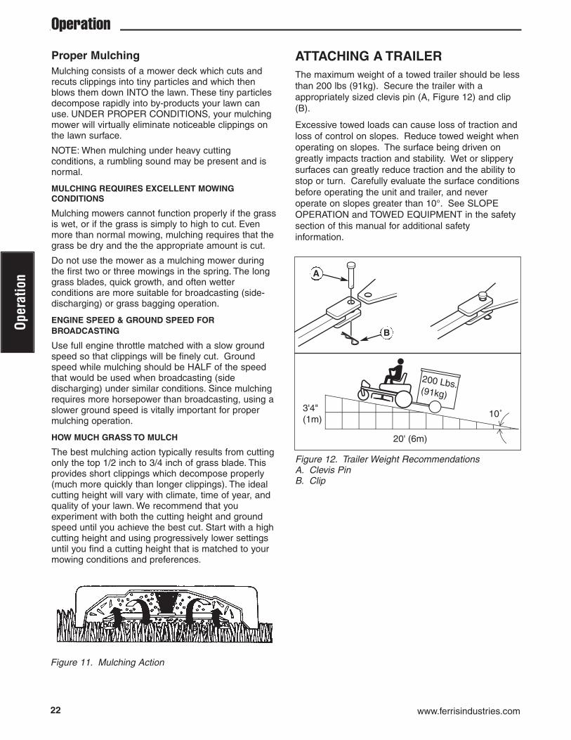
ATTACHING A TRAILERThe maximum weight of a towed trailer should be lessthan 200 lbs (91kg). Secure the trailer with aappropriately sized clevis pin (A, Figure 12) and clip(B).
Excessive towed loads can cause loss of traction andloss of control on slopes. Reduce towed weight whenoperating on slopes. The surface being driven ongreatly impacts traction and stability. Wet or slipperysurfaces can greatly reduce traction and the ability tostop or turn. Carefully evaluate the surface conditionsbefore operating the unit and trailer, and neveroperate on slopes greater than 10°. See SLOPEOPERATION and TOWED EQUIPMENT in the safetysection of this manual for additional safetyinformation.
A
B
22 www.ferrisindustries.com
Oper
atio
n
Proper MulchingMulching consists of a mower deck which cuts andrecuts clippings into tiny particles and which thenblows them down INTO the lawn. These tiny particlesdecompose rapidly into by-products your lawn canuse. UNDER PROPER CONDITIONS, your mulchingmower will virtually eliminate noticeable clippings onthe lawn surface.
NOTE: When mulching under heavy cuttingconditions, a rumbling sound may be present and isnormal.
MULCHING REQUIRES EXCELLENT MOWINGCONDITIONS
Mulching mowers cannot function properly if the grassis wet, or if the grass is simply to high to cut. Evenmore than normal mowing, mulching requires that thegrass be dry and the the appropriate amount is cut.
Do not use the mower as a mulching mower duringthe first two or three mowings in the spring. The longgrass blades, quick growth, and often wetterconditions are more suitable for broadcasting (side-discharging) or grass bagging operation.
ENGINE SPEED & GROUND SPEED FORBROADCASTING
Use full engine throttle matched with a slow groundspeed so that clippings will be finely cut. Groundspeed while mulching should be HALF of the speedthat would be used when broadcasting (sidedischarging) under similar conditions. Since mulchingrequires more horsepower than broadcasting, using aslower ground speed is vitally important for propermulching operation.
HOW MUCH GRASS TO MULCH
The best mulching action typically results from cuttingonly the top 1/2 inch to 3/4 inch of grass blade. Thisprovides short clippings which decompose properly(much more quickly than longer clippings). The idealcutting height will vary with climate, time of year, andquality of your lawn. We recommend that youexperiment with both the cutting height and groundspeed until you achieve the best cut. Start with a highcutting height and using progressively lower settingsuntil you find a cutting height that is matched to yourmowing conditions and preferences.
Figure 11. Mulching Action
Operation
23
Maintenance
STORAGE
Temporary Storage (30 Days Or Less)Remember, the fuel tank will still contain somegasoline, so never store the unit indoors or in anyother area where fuel vapor could travel to anyignition source. Fuel vapor is also toxic if inhaled, sonever store the unit in any structure used for humanor animal habitation.
Here is a checklist of things to do when storing yourunit temporarily or in between uses:
• Keep the unit in an area away from where childrenmay come into contact with it. If there’s anychance of unauthorized use, remove the sparkplug (s) and put in a safe place. Be sure the sparkplug opening is protected from foreign objects witha suitable cover.
• If the unit can’t be stored on a reasonable levelsurface, chock the wheels.
• Clean all grass and dirt from the mower.
Long Term Storage (Longer Than 30Days)Before you store your unit for the off-season, read theMaintenance and Storage instructions in the SafetyRules section, then perform the following steps:
1. Drain crankcase oil while engine is hot and refillwith a grade of oil that will be required when unitis used again.
2. Prepare the mower deck for storage as follows:
a. Remove mower deck from the unit.
b. Clean underside of mower deck.
c. Coat all bare metal surfaces with paint or lightcoat of oil to prevent rusting.
3. Clean external surfaces and engine.4. Prepare engine for storage. See engine owner’s
manual.5. Clean any dirt or grass from cylinder head cooling
fins, engine housing and air cleaner element.6. Cover air cleaner and exhaust outlet tightly with
plastic or other waterproof material to keep outmoisture, dirt and insects.
7. Completely grease and oil unit as outlined in theNormal Care section.
8. Clean up unit and apply paint or rust preventativeto any areas where paint is chipped or damaged.
9. Be sure the battery is filled to the proper level withwater and is fully charged. Battery life will beincreased if it is removed, put in a cool, dry placeand fully charged about once a month. If battery isleft in unit, disconnect the negative cable.
WARNINGNever store the unit, with gasoline in engine orfuel tank, in a heated shelter or in enclosed,poorly ventilated enclosures. Gasoline fumesmay reach an open flame, spark or pilot light(such as a furnace, water heater, clothes dryer,etc.) and cause an explosion.
Handle gasoline carefully. It is highly flammableand careless use could result in serious firedamage to your person or property.
Drain fuel into an approved container outdoorsaway from open flame or sparks.
10. Drain fuel system completely or add a gasolinestabilizer to the fuel system. If you have chosen touse a fuel stabilizer and have not drained the fuelsystem, follow all safety instructions and storageprecautions in this manual to prevent thepossibility of fire from the ignition of gasolinefumes. Remember, gasoline fumes can travel todistant sources of ignition and ignite, causing riskof explosion and fire.
NOTE: Gasoline, if permitted to stand unused forextended periods (30 days or more), may developgummy deposits which can adversely affect theengine carburetor and cause engine malfunction. Toavoid this condition, add a gasoline stabilizer to thefuel tank and run the engine a few minutes, or drainall fuel from the unit before placing it in storage.
STARTING AFTER LONG TERMSTORAGEBefore starting the unit after it has been stored for along period of time, perform the following steps.
1. Remove any blocks from under the unit.2. Install the battery if it was removed.3. Unplug the exhaust outlet and air cleaner.4. Fill the fuel tank with fresh gasoline. See engine
manual for recommendations.5. See engine owner’s manual and follow all
instructions for preparing engine after storage.6. Check crankcase oil level and add proper oil if
necessary. If any condensation hasdeveloped during storage, drain crankcase oil andrefill.
7. Inflate tires to proper pressure. Check fluid levels.8. Start the engine and let it run slowly. DO NOT run
at high speed immediately after starting. Be sureto run engine only outdoors or in well ventilatedarea.
Operation
24 www.ferrisindustries.com
Mai
nten
ance
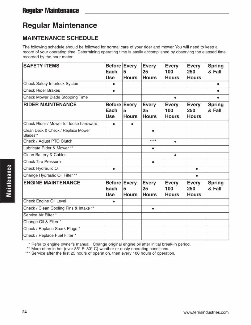
MAINTENANCE SCHEDULEThe following schedule should be followed for normal care of your rider and mower. You will need to keep arecord of your operating time. Determining operating time is easily accomplished by observing the elapsed timerecorded by the hour meter.
SAFETY ITEMS BeforeEachUse
Every 5 Hours
Every 25 Hours
Every100Hours
Every250Hours
Spring& Fall
Check Safety Interlock System • •Check Rider Brakes • •Check Mower Blade Stopping Time • •RIDER MAINTENANCE Before
Check Engine Oil Level •Check / Clean Cooling Fins & Intake ** •Service Air Filter *
Change Oil & Filter *
Check / Replace Spark Plugs *
Check / Replace Fuel Filter *
* Refer to engine owner’s manual. Change original engine oil after initial break-in period.** More often in hot (over 85° F: 30° C) weather or dusty operating conditions.
*** Service after the first 25 hours of operation, then every 100 hours of operation.
CHECK TIRE PRESSURESTire pressure should be checked periodically, andmaintained at the levels shown in the chart. Note thatthese pressures may differ slightly from the “MaxInflation” stamped on the side-wall of the tires. Thepressures shown provide proper traction, improve cutquality, and extend tire life.
CHECKING / ADDING FUELTo add fuel:
1. Remove the fuel cap (see Figure 1).2. Fill the tank to the bottom of the filler neck. This
will allow for fuel expansion.NOTE: Do not overfill. Refer to your engine manualfor specific fuel recommendations.
3. Install and hand tighten the fuel cap.
FUEL FILTERThe fuel filter is located in the fuel line between fueltank and carburetor, near the fuel pump. If filter isdirty or clogged, replace as follows:
1. Disconnect the negative battery cable.2. Place a container below the filter to catch spilled
fuel.3. Using pliers, open and slide hose clamps from fuel
filter.4. Remove hoses from filter.5. Install new filter in proper flow direction in fuel line.6. Secure with hose clamps.7. Reconnect the negative battery cable when
finished.
CHANGE OIL & FILTER1. Warm engine by running for a few minutes. (Refer
to the engine operator’s manual for oil & filterreplacement instructions.)
2. Remove the oil drain hose (A, Figure 14) from thecable clamp (C) that is located underneath theengine deck on the left-hand side of the frame.
3. Place a small pan under the oil drain hose tocatch the oil. Using the appropriate tools, removethe cap (B, Figure 14) from the oil drain hose (A)and drain the engine oil into the pan.
4. After draining, replace the cap and wipe up anyspilled oil. Reinstall the oil drain hose into thecable clamp to retain the hose during normaloperation.
5. Place an absorbent shop cloth under the engineoil filter. Remove the engine oil filter and replacewith a new one.
6. Remove the shop cloth and wipe up any spilledoil.
WARNINGGasoline is highly flammable and must behandled with care. Never fill the tank when theengine is still hot from recent operation. Do notallow open flame, smoking or matches in thearea. Avoid over-filling and wipe up any spills.
Do not remove fuel filter when engine is hot, asspilled gasoline may ignite. DO NOT spreadhose clamps further than necessary. Ensureclamps grip hoses firmly over filter afterinstallation.
Do not use gasoline containing METHANOL,gasohol containing more than 10% ethanol,gasoline additives, premium gasoline, orwhite gas because engine/fuel systemdamage could result.
ENGINE MAINTENANCERefer to engine owner’s manual for all enginemaintenance procedures and recommendations.
C
B A
26 www.ferrisindustries.com
Mai
nten
ance
Regular Maintenance
LUBRICATIONLubricate the unit at the locations shown in Figures15 through 18 as well as the following lubricationpoints.
Grease:• front caster wheel axles & yokes• deck lift pivot blocks• mower deck spindles• mower deck idler arm
Use grease fittings when present. Disassemble partsto apply grease to moving parts when grease fittingsare not installed.
Not all greases are compatible. Ferris Red Grease(p/n 5022285) is recommended, automotive-typehigh-temperature, lithium grease may be used whenthis is not available.
Oil:• control handle pivots• seat plate pivots• deck lift pivots• discharge chute hinge
Generally, all moving metal parts should be oiledwhere contact is made with other parts. Keep oil andgrease off belts and pulleys. Remember to wipefittings and surfaces clean both before and afterlubrication.
Lubricating the Front Casters:
NOTE: Front casters should be lubricated annually.1. Remove the 1/4-28 bolt (A, Figure 18) screwed
into the front caster and install a 1/4-28 greasefitting.
2. Grease the front caster.3. Remove the 1/4-28 grease fitting and reinstall the
1/4-28 bolt.4. Repeat process for the other side of the machine.
Figure 15. Deck Lubrication
Figure 17. Deck Lift Linkage Pivots
Figure 18. Front Caster & WheelA. 1/4-28 Bolt
Figure 16. Control Handle Pivots & Seat Plate Pivots
WARNINGBe careful when handling the battery. Avoidspilling electrolyte. Keep flames and sparksaway from the battery.
When removing or installing battery cables,disconnect the negative cable FIRST andreconnect it LAST. If not done in this order, thepositive terminal can be shorted to the frame bya tool.
CHECK HYDRAULIC OIL LEVEL1. Before removing the reservoir cap, make sure the
area around the reservoir cap and fill neck of thereservoir is free of dust, dirt, or other debris.
2. Unscrew the reservoir cap (B, Figure 19).3. Look down the filler neck of the hydraulic oil
reservoir (A, Figure 19) and observe the oil level.When cold, the oil level should be approximately4” (10 cm) below top of the filler neck.
4. If necessary, add SAE 20W-50 motor oil. DO NOTuse synthetic oils.
5. Reinstall the reservoir cap.
CHANGE HYDRAULIC OIL FILTERChange Interval: Every 250 Hours
Filter Part Number: 1719168
NOTE: Removing the oil filter from the filter base willdrain the oil reservoir. Have a suitable containerready to catch any spilled oil. Ferris recommends thisbe a dealer-only service item.
1. Locate the transmission oil filter (E, Figure 20) atthe rear of the battery compartment under theseat.
2. Lubricate the new filter base with a few drops oftransmission oil. Fill the filter half full of oil.
3. Clean the area around the filter base and removethe filter. Do NOT drain the hydraulic system oil.
4. Thread the new filter onto the filter base until thegasket makes contact, then tighten 3/4 of a turnmore.
5. Run the unit for several minutes and check thetransmission oil level.
IMPORTANT NOTE: Use caution after changing thefilter; air in the hydraulic system may affect theresponsiveness of the control levers. Repeat step 5until the air is out of the system.
BATTERY MAINTENANCENOTE: This unit is equipped with a maintenance-freeBCIU1 battery.
Cleaning the Battery and Cables1. Remove the hydraulic oil reservoir mounting
hardware (C, Figure 20) and then move thereservoir (D) forward to expose the battery.
2. Disconnect the cables from the battery, negative(black) cable first (B).
3. Clean the battery terminals and cable ends with awire brush until shiny.
4. Reinstall the battery and reattach the batterycables, positive (red) cable first (A).
5. Coat the cable ends and battery terminals withpetroleum jelly or non-conducting grease.
6. Reposition the oil reservoir and secure in placewith the hardware previously removed.
D
E
B
A
C
C
28 www.ferrisindustries.com
Mai
nten
ance
Regular Maintenance
Figure 22. Balancing The Blade
Figure 23. Installing The BladeA. Blade BoltB. Flat Washer
Nail
SERVICING THE MOWER BLADES1. Blades should be sharp and free of nicks and
dents. If not, sharpen blades as described in thefollowing steps.
2. To remove blade for sharpening, use a 1” wrenchon the flats of the spindle shaft while removing theblade mounting bolt with a 15/16” wrench (Figure21).
3. Use a file to sharpen blade to fine edge. Removeall nicks and dents in blade edge. If blade isseverely damaged, it should be replaced.
4. Balance the blade as shown in Figure 22. Centerthe blade’s hole on a nail lubricated with a drop ofoil. A balanced blade will remain level.
5. Reinstall each blade with the tabs pointing uptoward deck as shown in Figure 23. Secure with abolt and flat washer and torque bolts to 70 ft.lbs.(94 N.m.).
Figure 21. Removing the Blade
WARNINGMower blades are sharp. For your personalsafety, do not handle mower blades with barehands. Careless or improper handling ofblades may result in serious injury. For yourpersonal safety, blade mounting bolts musteach be installed with a flat washer thensecurely tightened. Torque blade mountingbolts to 70 ft.lbs. (94 N.m.)
29
Troubleshooting
TROUBLESHOOTING CHARTWhile normal care and regular maintenance willextend the life of your equipment, prolonged orconstant use may eventually require that service beperformed to allow it to continue operating properly.
The troubleshooting guide below lists the mostcommon problems, their causes and remedies.
See the information on the following pages forinstructions on how to perform most of these minoradjustments and service repairs yourself. If you prefer,all of these procedures can be performed for you byyour local authorized dealer.
WARNINGTo avoid serious injury, perform maintenanceon the tractor or mower only when the engineis stopped and the parking brake engaged.
Always remove the ignition key, disconnect thespark plug wire and fasten it away from theplug before beginning the maintenance, toprevent accidental starting of the engine.
TROUBLESHOOTING THE RIDERPROBLEM CAUSE REMEDYEngine will not turnover or start. 1. Parking brake not engaged. 1. Engage parking brake.
2. PTO (electric clutch) switch 2. Place in OFF position.in ON position.
3. Out of fuel. 3. If engine is hot, allow it to cool, then refill the fuel tank.
4. Engine flooded. 4. Move choke control to closed position.5. Fuse blown. 5. Replace fuse.6. Battery terminals require 6. Clean the battery terminals
cleaning.7. Battery discharged or dead. 7. Recharge or replace.8. Wiring loose or broken. 8. Visually check wiring & replace broken or
frayed wires. Tighten loose connections.9. Solenoid or starter motor faulty. 9. Repair or replace. See authorized dealer 10. Safety interlock switch 10. Replace as needed. See authorized
faulty. service dealer.11. Spark plug(s) faulty, fouled 11. Clean and gap or replace.
or incorrectly gapped. See engine manual.12. Water in fuel. 12. Drain fuel & replace with fresh fuel.13. Gas is old or stale. 13. Drain fuel & replace with fresh fuel.
Engine starts hard or runs poorly. 1. Fuel mixture too rich. 1. Clean air filter. Check choke adjustment.2. Spark plug faulty, fouled, or 2. Clean and gap or replace.
incorrectly gapped. (See engine manual.)
Engine knocks. 1. Low oil level. 1. Check/add oil as required.2. Using wrong grade oil. 2. See engine manual.
2. Using wrong weight oil. 2. See engine manual.3. Too much oil in crankcase. 3. Drain excess oil.
Engine exhaust is black. 1. Dirty air filter. 1. Replace air filter. See engine manual.2. Engine choke control 2. Open choke control.
is in closed position.
Troubleshooting, Adjustment & Service
Troubleshooting
30 www.ferrisindustries.com
Trou
bles
hoot
ing
Rider Troubleshooting Continued.PROBLEM CAUSE REMEDYEngine runs, but rider will 1. Hydraulic release valve(s) 1. Turn valve(s) clockwise to close.not drive. in “open” position.
2. Belt is broken. 2. See Drive Belt Replacement.3. Drive belt slips. 3. See problem and cause below.4. Brake is not fully released. 4. See authorized service dealer
Rider drive belt slips. 1. Pulleys or belt greasy or oily. 1. Clean as required.2. Tension too loose. 2. Adjust spring tension.
See Drive Belt Replacement3. Belt stretched or worn. 3. Replace belt.
Brake will not hold. 1. Brake is incorrectly adjusted. 1. See Brake Adjustment.2. Brake pads worn. 2. Replace with new brake pads.
Rider steers or handles poorly. 1. Steering linkage is loose. 1. Check and tighten any loose connections.2. Improper tire inflation. 2. See Regular Maintenance Section.
TROUBLESHOOTING THE MOWERPROBLEM CAUSE REMEDYMower will not raise. 1. Lift linkage not properly attached 1. See authorized service dealer for repair.
or damaged.
Engine stalls easily with 1. Engine speed too slow. 1. Set to full throttle.mower engaged. 2. Ground speed too fast. 2. Decrease Ground Speed.
3. Cutting height set too low. 3. Cut tall grass at maximum cuttingheight during first pass.
Excessive mower vibration. 1. Blade mounting bolts are loose. 1. Tighten to 70 ft.lbs. (94 N.m.).2. Mower blades, arbors, 2. Check and replace as necessary.
or pulleys are bent.3. Mower blades are out 3. Remove, sharpen, and balance blades.
of balance. See Maintenance Section.4. Belt installed incorrectly. 4. Reinstall Correctly.
Excessive belt wear or breakage. 1. Bent or rough pulleys. 1. Repair or replace.2. Using incorrect belt. 2. Replace with correct belt.
Mower drive belt slips 1. Idler pulley spring broken or not 1. Repair or replace as needed.or fails to drive. properly attached.
2. Mower drive belt broken. 2. Replace drive belt.
Mower does not engage. 1. Electrical wiring damage. 1. Locate & repair damaged wire.2. PTO clutch not adjusted 2. See PTO Clutch Adjustment section3. Battery voltage too low. 3. Recharge battery and check alternator.
See Battery Maintenance section.
Troubleshooting, Adjustment & Service
31
Troubleshooting
TROUBLESHOOTING COMMON CUTTING PROBLEMSPROBLEM CAUSE REMEDYStreaking. 1. Blades are not sharp. 1. Sharpen your blades.
2. Blades are worn down to far. 2. Replace your blades.3. Engine speed is too slow. 3. Always mow at full throttle.4. Ground speed is too fast. 4. Slow down.5. Deck is plugged with grass 5. Clean out the mower.6. Not overlapping cutting rows 6. Overlap your cutting rows.
enough.7. Not overlapping enough when 7. When turning your effective cutting width
turning. decreases–overlap more when turning.
Scalping. 1. Lawn is uneven or bumpy. 1. Roll or level the lawn.2. Mower deck cutting height is 2. Raise the cutting height.
set too low.3. Ground speed is too fast. 3. Slow down.4. Deck is not leveled correctly. 4. Correctly level the deck.5. Tire pressure is low or uneven 5. Check and inflate the tires.
Stepped Cutting. 1. Deck is not leveled correctly. 1. Level the deck correctly.2. Tires are not properly inflated. 2. Check and inflate the tires.3. Blades are damaged. 3. Replace the blades.4. Deck shell is damaged. 4. Repair or replace the deck.5. Mower spindle is bent or loose. 5. Repair or replace the spindle.6. Blades are installed incorrectly. 6. Reinstall the blades correctly.
Uneven Cutting. 1. Deck is not leveled correctly. 1. Level the deck correctly.2. Blades are dull or worn. 2. Sharpen or replace the blades.3. Blades are damaged. 3. Replace the blades.4. Deck is clogged with grass 4. Clean out the deck.
clippings.5. Deck shell is damaged. 5. Repair or replace the deck.6. Mower spindle is bent or loose. 6. Repair or replace the spindle.7. Blades are installed incorrectly. 7. Reinstall the blades correctly.8. Tires are not properly inflated. 8. Check and inflate the tires.
Stingers. 1. Blades are not sharp or nicked. 1. Sharpen your blades.2. Blades are worn down too far. 2. Replace your blades.3. Engine speed is too slow. 3. Always mow at full throttle.4. Ground speed is too fast. 4. Slow down.5. Deck is plugged with grass. 5. Clean out the mower.
Troubleshooting, Adjustment & Service
32 www.ferrisindustries.com
Trou
bles
hoot
ing
Troubleshooting, Adjustment & Service
SEAT ADJUSTMENTSee Figure 24. The seat can be adjusted forward andbackward. Move the lever towards the left, positionthe seat as desired, and release the lever to lock theseat into position.
GROUND SPEED CONTROL LEVERADJUSTMENTThe control levers can be adjusted in three ways. Thealignment of the control levers, the placement of thelevers (how close the ends are to one another) andthe height of the levers can be adjusted.
To Adjust the Handle Alignment
Loosen the mount bolts (A, Figure 25) and pivot thelever(s) (C) to align with each other.
To Adjust the Handle Placement
Loosen the jam nuts and adjust the placement bolt(B, Figure 25) in or out to properly adjust the leverend spacing.
To Adjust the Handle Height
Remove the mounting hardware and reposition thehandle either up or down from its original position.You will need to readjust the handle alignment asdescribed above.
SPEED BALANCING ADJUSTMENTIf the rider veers to the right or left when the groundspeed control levers are in the maximum forwardposition, the top speed of each of these levers can bebalanced by turning the adjustment bolt(s) (A, Figure26). Only adjust the speed of the wheel that istraveling faster.
To Reduce the Speed of the Faster Wheel
1. Loosen the securing nut.2. Turn the top speed adjustment bolt COUNTER-
CLOCKWISE to reduce the speed.3. Retighten the securing nut when adjustment is
complete.
Seat AdjustmentLever
Figure 24. Seat Adjustment
Figure 25. Control Lever AdjustmentA. Alignment HardwareB. Placement HardwareC. Ground Speed Control Lever
WARNINGDO NOT adjust the tractor for a faster overallspeed forward or reverse than it was designedfor.
A
B
C
Figure 26. Top Speed AdjustmentA. Top Speed Adjustment BoltB. Control Lever Base
B
A
33
TroubleshootingTroubleshooting, Adjustment & Service
PARKING BRAKE ADJUSTMENT1. Disengage the PTO, engage the parking brake,
stop the engine and remove the ignition key.2. Raise the seat plate.3. Locate the brake spring (A, Figure 27).4. With the parking brake engaged, measure the
compressed spring length. The spring should be1-15/16” - 2” (4,9 - 5,1 cm) when compressed.
5. If the spring is not within this range, release theparking brake and turn the adjustment nut (B) tocompress or release the spring.
6. Engage the parking brake and remeasure thespring.
If this does not correct the braking problem, seeyour Ferris dealer.
A
B
CAUTIONDo not adjust the spring to be shorter than1-15/16” (4,9 cm) when compressed. This maydamage the brake mechanism.
34 www.ferrisindustries.com
Trou
bles
hoot
ing
Troubleshooting, Adjustment & Service
REAR SUSPENSION ADJUSTMENTThe shock assembly can be adjusted to allow theoperator to customize the ride according to operator’sweight and/or operating conditions. You have theoption of adjusting the spring pre-load.
Items to consider before adjusting the suspension.
• Less spring pre-load should be used with lightweight operators, which will provide a softer, morecushioned ride.
• More spring pre-load should be used with heavyweight operators, or when a rear-mount grassbagger system is installed, which will provide astiffer, more rigid ride.
To adjust the spring pre-load:
1. Park machine on a flat, level surface. Disengagethe PTO, stop the engine and engage the parkingbrake.
2. Raise the rear of the machine and secure withjackstands. Chock the front wheels to prevent themachine from rolling.
3. Remove the rear drive tires.4. See Figure 28. Using the supplied spanner
wrench (p/n 5022853), insert the tip of the wrenchinto the notch in the pre-load adjuster. Whileholding the wrench in place with one hand, turnCOUNTER-CLOCKWISE to increase the pre-load,turn CLOCKWISE to decrease the pre-load. Makesure both shocks are set to the same amount ofpre-load.
5. Reinstall the rear drive tires. Torque the lug boltsto 85-95 ft/lbs. (115-129 Nm). Remove thejackstands from under the machine.
NOTE: Spanner wrench is located under the seat onthe right-hand side of the machine.
NOTE: It is recommended that the rear suspensionbe adjusted stiffer due to the added weight of thecollection system.
WARNINGUse two hands when adjusting the shocksprings. This will prevent the wrench fromslipping while pressure is being applied.
Figure 28. Rear Suspension Adjustments
35
TroubleshootingTroubleshooting, Adjustment & Service
Figure 29. Neutral Return Spring AdjustmentA. Rear Set CollarB. Neutral Return RodC. Neutral Return SpringD. Front Set CollarE. Neutral Return BushingF. Spring Stop Plate
RETURN-TO-NEUTRALADJUSTMENTTo determine if it is necessary to adjust the neutralreturn, perform the following steps.
1. Disengage the PTO, engage the parking brakeand turn off the engine.
2. Move the ground speed control levers into theoperating position, pull levers rearward andrelease.
3. Move the ground speed control levers out towardsthe neutral position. If the levers do not align withthe notches in the neutral lock plate, it isnecessary to adjust the neutral return rod (B,Figure 29).
Adjustment
1. Lock the ground speed control lever in the neutralposition.
2. Measure the length of the neutral return spring (C,Figure 29) it should be set at 3.25” (8,23cm). If thespring does not measure 3.25” (8,23cm) loosenthe front set collar (D) and the rear set collar (A),then move the front set collar forward or back onthe neutral return rod (B) until the spring lengthequals 3.25” (8,23cm). Retighten the front setcollar.
3. Make sure that the neutral return bushing (E) isseated correctly in the spring stop plate (F).
4. Position the rear set collar so that it sets tightlyagainst neutral return bushing and tighten.
5. Pull the ground speed control lever rearward andrelease to check position again. Adjust asnecessary to align the ground speed control leverswith the notches in the neutral lock plate.
It is important to note that after every adjustment ofthe neutral return rod, the lever must be pulledrearward and released to properly check the neutralposition.
WARNINGTo avoid serious injury, perform adjustmentsonly with engine stopped, key removed andtractor on level ground.
E
BC
D3.25”
(8,23cm)
F A
36 www.ferrisindustries.com
Trou
bles
hoot
ing
Troubleshooting, Adjustment & Service
MOWING HEIGHT ADJUSTMENTThe cutting height adjustment pin (A, Figure 31)controls the mower cutting height. The cutting heightis adjustable between 1-3/4” (4,4 cm) and 4-1/2” (11,4cm) in 1/4” (0,64 cm) increments.
1. Depress the deck lift foot pedal (B) until it locksinto the 4-1/2” (11,4 cm) position.
2. Place the cutting height adjustment pin in thedesired cutting height.
3. Depress the deck lift foot pedal then push the locklever (C) towards the right to release the lock.
4. Release the deck lift foot pedal until it comes torest against the cutting height adjustment pin.
Figure 30. Neutral Adjustment(RH side shown)A. Adjustment Linkage RodB. Nuts
A
B
NEUTRAL ADJUSTMENTIf the tractor “creeps” while the ground speed controllevers are locked in NEUTRAL, then it may benecessary to adjust the linkage rod.
NOTE: Perform this adjustment on a hard, levelsurface such as a concrete floor.
1. Disengage the PTO, engage the parking brakeand turn off the engine.
2. There are three nuts (B, Figure 30) on the linkagerod. The first two are to be used together to turnthe rod and the third (towards the front of themachine) is used to lock the rod in place. Loosenthe jam nut that locks against the ball joint (B,Figure 30) and turn the linkage rod (A) to adjust.If the machine creeps forward, turn the rodCLOCKWISE (while standing at the rear of themachine, facing forward), if the machine creepsbackward, turn the rod COUNTER-CLOCKWISE.
3. Lock the jam nut (B) against the ball joint whenneutral is achieved.
NOTE: This adjustment should not be performedwhile the machine is running. It may take severalattempts to achieved neutral, depending upon howmuch the machine creeps.
37
TroubleshootingTroubleshooting, Adjustment & Service
DECK LEVELING ADJUSTMENT1. Park machine on a flat, level surface. Disengage
the PTO, stop the engine and engage the parkingbrake. Rear tires must be inflated to 15 psi (1,03bar); front tires to 40 psi (2,76 bar).
2. To check the lift rod timing, measure and recordthe distance between the lift pivots and the rodpivots. Repeat for other side of unit. See Figure32.
3. If the measurements are equal, skip to Step 5. Ifthe measurements are NOT equal (greater than1/8” (3,17mm) difference), adjustment is required,continue with Step 4.
4. Refer to Figure 33. To adjust the lift rod timing,adjust the 5/8” hex nuts on either side of the frontlift pivot until the measurements are equal.Repeat for other side.
5. Place the deck height adjustment pin in the4" (10,2 cm) position.
6. Place 2 x 4 blocks under each corner of themower deck with the 3-1/2” sides being vertical.Place a 1/4” (0,64 cm) thick spacer on top of therear 2 x 4 blocks. See Figure 34.
7. Adjust the front eyebolts until the chains are tightand the deck is still resting on the 2 x 4’s. Tightenjam nuts. See Figure 35.
8. Loosen the nuts and allow the rear of the deck torest on the 2 x 4’s and 1/4” spacers. Slide thechains in the slots until the chains are tight andtighten the nuts. See Figure 35.
9. Remove all 2 x 4 blocks and spacers from underthe mower deck.
Figure 32. Check Lift Rod Timing
Figure 33. Adjust Lift Rod Timing
Figure 34. 2 x 4 Locations
Figure 35. Hanger Chain Adjustment
38 www.ferrisindustries.com
Trou
bles
hoot
ing
Troubleshooting, Adjustment & Service
HYDRAULIC PUMP DRIVE BELTREPLACEMENT1. Park the tractor on a smooth, level surface such
as a concrete floor. Disengage the PTO, engagethe parking brake, turn off the engine, and removethe ignition key.
2. Remove the PTO drive belt (see MOWER BELTREPLACEMENT for removal instructions).
3. Remove the hardware that secures the clutchanchor pad to the PTO clutch.
4. Loosen the nut towards the front of the machineon the spring anchor hook (G, Figure 36) torelease the majority of the belt tension. Usecaution and remove the nut to completely releasethe tension.
5. Remove the old belt and replace it with the newone. Make sure the V-side of the belt runs in thegrooves of the crankshaft pulley and pump pulleys(B & C).
6. Reinstall the anchor hook (G) into the anchor taband loosely fasten the nut. Adjust the anchorhook until a measurement of 8-3/8” (21,2 cm) isachieved from the outside if the spring hooks.Tighten nut.
7. Reinstall the clutch anchor pad to the PTO clutchand secure with the hardware previously removed.
1. Park the tractor on a smooth, level surface suchas a concrete floor. Disengage the PTO, engagethe parking brake, turn off the engine, and removethe ignition key.
2. Lower the mower deck to its lowest cuttingposition and remove the mower deck guards.
3. 44” Models: Using a 1/2” breaker bar, place thesquare end in the square hole located in the endof the idler arm (A, Figures 37). Carefully rotatethe breaker bar clockwise, which will relieve thetension on the belt exerted from the idler arm.
3. 52” Models: Using a 1/2” breaker bar, place thesquare end in the square hole located in the endof the idler arm (A, Figures 37). Carefully rotatethe breaker bar counter-clockwise, which willrelieve the tension on the belt exerted from theidler arm.
4. Slide the drive belt over the edge of the stationaryidler pulley (B). Carefully release the tension onthe breaker bar.
5. Remove the old belt and replace with a new one.Make sure the V-side of the belt runs in the pulleygrooves (Figure 38).
6. 44” Models: Install the drive belt on the PTOpulley, the spindle pulleys and all idler pulleysexcept the stationary pulley (B, Figure 37).Carefully rotate the breaker bar clockwise andinstall the belt on the stationary idler pulley (B).Carefully release the tension on the breaker bar.
6. 52” Models: Install the drive belt on the PTOpulley, the spindle pulleys and all idler pulleysexcept the stationary pulley (B, Figure 37).Carefully rotate the breaker bar counter-clockwise and install the belt on the stationaryidler pulley (B). Carefully release the tension onthe breaker bar.
7. Reinstall the mower deck guards.8. Run the mower under no-load condition for about
5 minutes to break-in the new belt.
To avoid damaging belts, DO NOTPRY BELTS OVER PULLEYS.
WARNINGUse extreme caution when rotating the idlerarm with the breaker bar, due to the increasedtension in the spring as the idler arm is beingrotated. Injury may result if the breaker bar isprematurely released while the spring is undertension.
C
A
A
AD
CBD
A
A
AD
A
B
52” Deck
B
44” Deck
44” Deck
52” Deck
D
40 www.ferrisindustries.com
Trou
bles
hoot
ing
Troubleshooting, Adjustment & Service
BATTERY SERVICE
Checking Battery VoltageA voltmeter can be used to determine condition ofbattery. When engine is off, the voltmeter showsbattery voltage, which should be 12 volts. Whenengine is running, the voltmeter shows voltage ofcharging circuit which normally is 13 to 14 volts.
A dead battery or one too weak to start the enginemay not mean the battery needs to be replaced. Forexample, it may mean that the alternator is notcharging the battery properly. If there is any doubtabout the cause of the problem, see your dealer. Ifyou need to replace the battery, follow the stepsunder Cleaning the Battery & Cables in the RegularMaintenance Section.
Charging a Completely DischargedBattery1. Be aware of all the safety precautions you should
observe during the charging operation. If you areunfamiliar with the use of a battery charger andhydrometer, have the battery serviced by yourdealer.
2. Add distilled water sufficient to cover the plate (fillto the proper level near the end of the charge). Ifthe battery is extremely cold, allow it to warmbefore adding water because the water level willrise as it warms. Also, an extremely cold batterywill not accept a normal charge until it becomeswarm.
3. Always unplug or turn the charger off beforeattaching or removing the clamp connections.
4. Carefully attach the clamps to the battery inproper polarity (usually red to [+] positive andblack to [-] negative).
5. While charging, periodically measure thetemperature of the electrolyte. If the temperatureexceeds 125° F (51.6° C), or if violent gassing orspewing of electrolyte occurs, the charging ratemust be reduced or temporarily halted to preventbattery damage.
6. Charge the battery until fully charged (until thespecific gravity of the electrolyte is 1.250 or higherand the electrolyte temperature is at least 60° F).The best method of making certain a battery isfully charged, but not over charged, is to measure
WARNINGKeep open flames and sparks away from thebattery; the gasses coming from it are highlyexplosive. Ventilate the battery well duringcharging.
the specific gravity of a cell once per hour. Thebattery is fully charged when the cells are gassingfreely at low charging rate and less than 0.003change in specific gravity occurs over a three hourperiod.
Jump Starting With Auxiliary (Booster)BatteryJump starting is not recommended. However, if itmust be done, follow these directions. Both boosterand dis-charged batteries should be treated carefullywhen using jumper cables. Follow the steps belowEXACTLY, being careful not to cause sparks. Refer toFigure 39.
1. Both batteries must be of the same voltage.2. Position the vehicle with the booster battery
adjacent to the vehicle with the discharged batteryso that booster cables can be connected easily tothe batteries in both vehicles. Make certainvehicles do not touch each other.
3. Wear safety glasses and shield eyes and facefrom batteries at all times. Be sure vent caps aretight. Place damp cloth over vent caps on bothbatteries.
4. Connect positive (+) cable to positive post ofdischarged battery (wired to starter or solenoid).
5. Connect the other end of same cable to samepost marked positive (+) on booster battery.
6. Connect the second cable negative (-) to otherpost of booster battery.
7. Make final connection on engine block of stalledvehicle away from battery. Do not lean overbatteries.
8. Start the engine of the vehicle with the boosterbattery. Wait a few minutes, then attempt to startthe engine of the vehicle with the dischargedbattery.
9. If the vehicle does not start after cranking for thirtyseconds, STOP PROCEDURE. More than thirtyseconds seldom starts the engine unless somemechanical adjustment is made.
10. After starting, allow the engine to return to idlespeed. Remove the cable connection at theengine or frame. Then remove the other end of thesame cable from the booster battery.
11. Remove the other cable by disconnecting at thedischarged battery first and then disconnect theopposite end from the booster battery.
12. Discard the damp cloths that were placed over thebattery vent caps.
41
Troubleshooting
To StarterSwitch
StartingVehicleBattery
To Ground
To Starter Switch
DischargedVehicle Battery
EngineBlock
THIS HOOK-UP FOR NEGATIVE GROUND VEHICLES
MAKE CERTAIN VEHICLES DO NOT TOUCH
Jumper Cable
Jumper Cable
WARNINGAny procedure other than the preceding couldresult in:
(1) personal injury caused by electrolytesquirting out the battery vents,
(2) personal injury or property damage dueto battery explosion,
(3) damage to the charging system of thebooster vehicle or of the immobilizedvehicle.
Do not attempt to jump start a vehicle having afrozen battery because the battery may ruptureor explode. If a frozen battery is suspected,examine all fill vents on the battery. If ice canbe seen or if the electrolyte fluid cannot beseen, do not attempt to start with jumpercables as long as the battery remains frozen.
WARNINGFor your personal safety, use extreme carewhen jump starting. Never expose battery toopen flame or electric spark – battery actiongenerates hydrogen gas which is flammableand explosive. Do not allow battery acid tocontact skin, eyes, fabrics, or painted surfaces.Batteries contain a sulfuric acid solution whichcan cause serious personal injury or propertydamage.
When removing or installing battery cables,disconnect the negative cable FIRST andreconnect it LAST. If not done in this order, thepositive terminal can be shorted to the frameby a tool.
To avoid engine damage, do not disconnectbattery while engine is running. Be sureterminal connections are tight before starting.
Figure 39. Jump Starting
Troubleshooting, Adjustment & Service
42 www.ferrisindustries.com
Spec
ifica
tions
ENGINE:
24 HP Briggs & StrattonMake Briggs & StrattonModel 44M777-0113-E1Horsepower 24 @ 3500 rpmDisplacement 44.2 Cu. in (725 cc)Electrical System 12 Volt, 16 amp. Alternator, Battery: 340CCAOil Capacity 4 US pt. ( 1.9L) w/ Filter
26 HP Briggs & StrattonMake Briggs & StrattonModel 44M777-0120-E1Horsepower 26 @ 3600 rpmDisplacement 44.2 Cu. in (725 cc)Electrical System 12 Volt, 16 amp. Alternator, Battery: 340CCAOil Capacity 4 US pt. ( 1.9L) w/ Filter
CHASSIS:Fuel Tank Capacity: 6 Gallons (22.7 L)Rear Wheels44” Model Tire Size: 20 x 8.00 -10
Inflation Pressure: 15 psi (1,03 bar)52” Model Tire Size: 20 x 10.00 -10
Inflation Pressure: 15 psi (1,03 bar)
Front Wheels Tire Size: 11 x 4.00 - 5Inflation Pressure: 40 psi (2,76 bar)
NOTE: Specifications are correct at time of printing and are subject to change without notice.
Specifications
Engine Power Rating Information
The gross power rating for individual gas engine models is labeled in accordance with SAE (Society ofAutomotive Engineers) code J1940 (Small Engine Power & Torque Rating Procedure), and rating performancehas been obtained and corrected in accordance with SAE J1995 (Revision 2002-05). Torque values are derivedat 3060 RPM; horsepower values are derived at 3600 RPM. Actual gross engine power will be lower and isaffected by, among other things, ambient operating conditions and engine-to-engine variability. Given both thewide array of products on which engines are placed and the variety of environmental issues applicable tooperating the equipment, the gas engine will not develop the rated gross power when used in a given piece ofpower equipment (actual "on-site" or net power). This difference is due to a variety of factors including, but notlimited to, accessories (air cleaner, exhaust, charging, cooling, carburetor, fuel pump, etc.), applicationlimitations, ambient operating conditions (temperature, humidity, altitude), and engine-to-engine variability. Dueto manufacturing and capacity limitations, Briggs & Stratton may substitute an engine of higher rated power forthis Series engine.
Specifications
Thank you for purchasing Ferris commercial mowing equipment. Please take a few minutes to read this limited warranty information. It contains allthe information you will need to have your Ferris mower repaired in the unlikely event that a breakdown covered by this limited warranty should occur.
Owner's Responsibilities - As a condition to our obligations under this limited warranty, you shall have read the operator's manual and you shall havecompleted and submitted to Ferris, within 20 days from the date of purchase, the Ferris Product Registration. You must properly service and maintainyour Ferris product as described in the operator's manual. Such routine maintenance, whether performed by a dealer or by you, is at your expense.The Ferris equipment, including any defective part covered by this limited warranty, must be returned to an authorized Ferris dealer within the warrantyperiod for warranty service. This limited warranty extends only to equipment operated under normal conditions and in accordance with Ferris' instruc-tions.
Warranty Start Date - The limited warranty coverage begins on the day you buy your new Ferris commercial mowing equipment. An authorized Ferrisdealer will assist you in filling out a Ferris Product Registration with specific information for the model you purchase and your personal information,which must be returned to Ferris.
Limited Warranty - The limited warranty, set forth below, is a written guarantee by Ferris, during the warranty period, to repair or replace parts whichhave a substantial defect in materials or workmanship. The warranty is "limited" because it is for a specified period of time, applies to the original pur-chaser only, and is subject to other restrictions.
FERRIS LIMITED WARRANTY
Ferris Industries (Ferris) warrants, in accordance with the provisions below, to the original purchaser only, for the periods described below that thecommercial mower shall be free from substantial defects in material or workmanship under normal use and service. If you wish to file a claim underthis limited warranty, you must provide prompt notice of your claim to an authorized Ferris dealer during the warranty period. Ferris' obligation underthis limited warranty is, at Ferris' option, to repair or replace any part or parts of the mower, which, in the judgment of Ferris, are found to be defectiveand covered by this limited warranty. An authorized Ferris dealer will repair or replace the defective part or parts, at the dealer's place of business, atno charge for the labor or parts. This limited warranty applies only to mowers sold in the United States and Canada and is subject to the following limi-tations.
Covered Parts Warranty PeriodAll Mowers 2-years (24 months) from date of retail purchase by the original
purchaser for parts & labor (90 days for rental mowers)(Except as noted below*)
*Belts, Tires, Brake Pads 90 days from date of retail purchase by the original purchaserAnd Hoses, Battery, Blades
*Attachments 1 year from date of retail purchase by the original purchaser
*Engine If the engine manufacturer provides any warranty on the mower's engine, Ferris will assign that warranty to theoriginal purchaser of the mower if such assignment is reasonably practicable. Please refer to the engine man-ufacturer's warranty statement, if any, that is included in the owner's packet. We are not authorized to handle warranty adjustments or repairs on engines. Ferris offers NO WARRANTY on mower engines. Ferris does notguarantee or represent that any engine manufacturer will comply with the terms of its warranty.
Items and Conditions Not CoveredThis warranty does not cover, and Ferris makes NO WARRANTY regarding, the following:
• Mowers or their parts if a complete and accurate Ferris Product Registration has not been received by Ferris.• Loss or damage to person or property other than that expressly covered by the terms of this limited warranty.• Pickup and delivery charges and risk of loss or damage in transit to and from any authorized Ferris dealer.• Any damage or deterioration due to normal use, wear and tear, or environmental or natural elements, or exposure.• Cost of regular maintenance service or parts, such as but not limited to, filters, fuel, lubricants, tune-up parts, and adjustments.• Claims arising due to failure to follow Ferris' written instructions, or improper storage or maintenance.• Any repairs necessary due to use of parts, accessories or supplies, including gasoline, oil or lubricants, incompatible with the mowing equipment,
or other than as recommended in the operator's manual or other written operational instructions provided by Ferris.• Use of non-Ferris approved parts or accessories.• Any overtime or other extraordinary repair charges or charges relating to repairs or replacements.• Rental of like or similar replacement equipment during the period of any warranty, repair or replacement work.• Loss of revenue, time or use of the mowing equipment.• Travel, telephone or other communication charges.• Damage from continued use of defective mowing equipment.• Freight charges on replacement parts.• Any mowing equipment or part which, in the judgment of Ferris, has been altered or tampered with in any way or has been subjected to misuse,
abuse, abnormal usage, unauthorized repair, neglect or accident, damage in transit, or has had the serial numbers altered, effaced or removed.• Any equipment, part or item not mentioned under "Covered Parts," above.
General ConditionsFerris is continually striving to improve its products, and therefore reserves the right to make improvements or changes without incurring any obligationto make changes or additions to products sold previously. Any oral or written description of Ferris products is for the sole purpose of identifying theproducts and shall not be construed as an express warranty. No warranty claim shall give rise to a right for the purchaser to cancel or rescind anysale. No person is authorized to make any warranty or assume for Ferris any liability not strictly in accordance with this limited warranty. Any assis-tance Ferris provides to or procures for the purchaser outside the terms, limitations or exclusions of this limited warranty will not constitute a waiver ofthe terms, limitations or exclusions of this limited warranty, nor will such assistance extend or revive the limited warranty. Ferris will not reimburse thepurchaser for any expenses incurred by the purchaser in repairing, correcting or replacing any defective products except for those incurred with Ferris'prior written permission and in accordance with this limited warranty.
Ferris' sole and exclusive liability with respect to this limited warranty, and the purchaser's exclusive remedy, shall be repair or replacement as set forthherein. All warranty work must be performed by an authorized Ferris dealer using only Ferris approved replacement parts. FERRIS SHALL HAVE NOLIABILITY FOR ANY OTHER COST, LOSS OR DAMAGE, INCLUDING BUT NOT LIMITED TO, ANY INCIDENTAL, COMPENSATORY, INDIRECT,PUNITIVE, SPECIAL OR CONSEQUENTIAL LOSS OR DAMAGE. FERRIS' AGGREGATE LIABILITY WITH RESPECT TO A DEFECTIVE PROD-UCT OR PART SHALL BE LIMITED TO AN AMOUNT EQUAL TO THE MONIES PAID BY THE PURCHASER FOR THAT DEFECTIVE PRODUCTOR PART. THIS LIMITED WARRANTY, AND FERRIS' OBLIGATIONS HEREUNDER, ARE EXCLUSIVE AND IN LIEU OF ALL OTHER WAR-RANTIES, EXPRESS OR IMPLIED, INCLUDING, WITHOUT LIMITATION, THE IMPLIED WARRANTY OF MERCHANTABILITY AND THE IMPLIEDWARRANTY OF FITNESS FOR A PARTICULAR PURPOSE. FERRIS SHALL NOT BE LIABLE TO THE PURCHASER, OR TO ANYONE CLAIMINGUNDER THE PURCHASER, FOR ANY OTHER OBLIGATIONS OR LIABILITIES, INCLUDING, BUT NOT LIMITED TO, OBLIGATIONS OR LIABILI-TIES ARISING OUT OF BREACH OF CONTRACT OR WARRANTY, NEGLIGENCE OR OTHER TORT OR ANY THEORY OF STRICT LIABILITY,WITH RESPECT TO FERRIS PRODUCTS OR FERRIS' ACTS OR OMISSIONS OR OTHERWISE.
It is the express wish of the parties that this agreement and any related documents be drafted in English. Il est la volonté expresse des parties quecette convention et tous les documents s'y rattachent soient rédigés en anglais.
Ferris Industries - a division of Simplicity Manufacturing Inc.Owner's Limited Warranty Information
(Effective 04/28/2004)
Briggs & Stratton Yard Power Products Group5375 North Main StreetMunnsville, NY 13409800-933-6175www.ferrisindustries.com
IS500Z SeriesZero-Turn Riding Mower
OPERATOR’SMANUAL
ENGINE:
24 HP Briggs & StrattonMake Briggs & StrattonModel 44M777-0113-E1Oil Capacity 4 US pt. ( 1.9L) w/ Filter
26 HP Briggs & StrattonMake Briggs & StrattonModel 44M777-0120-E1Oil Capacity 4 US pt. ( 1.9L) w/ Filter
CHASSIS:Fuel Tank Capacity: 6 Gallons (22.7 L)Rear Wheels44” Models Tire Size: 20 x 8.00 -10