TECHNICAL PROVISIONS Honolulu High-Capacity Transit Corridor Project October 2010 Core Systems Design-Build-Operate-Maintain Contract TP-2: Verification Test and Acceptance Honolulu High-Capacity Transit Corridor Project October 2010 Prepared for: City and County of Honolulu
Transcript
TECHNICAL PROVISIONS Honolulu High-Capacity Transit Corridor Project October 2010 Core Systems Design-Build-Operate-Maintain Contract
TP-2: Verification Test and Acceptance Honolulu High-Capacity Transit Corridor Project
October 2010
Prepared for: City and County of Honolulu
TECHNICAL PROVISIONS Honolulu High-Capacity Transit Corridor Project October 2010 Core Systems Design-Build-Operate-Maintain Contract
TP-2 VERIFICATION TEST AND ACCEPTANCE Page i
TABLE OF CONTENTS
TP-2.1 GENERAL ........................................................................................................................................ 1
TP-2.2 VTA REQUIREMENTS ................................................................................................................... 1 TP-2.2.1 General ...................................................................................................... 1 TP-2.2.2 VTA Program ........................................................................................... 1
TP-2.2.2.1 VTA Program Outline ................................................................. 1 TP-2.2.2.2 VTA Program Categories ............................................................ 2 TP-2.2.2.3 VTA Program Numbering Scheme .............................................. 2
TP-2.3 VTA PLAN ....................................................................................................................................... 2
TP-2.4 TEST MANAGEMENT PLAN ........................................................................................................ 3 TP-2.4.1 Test Organization ...................................................................................... 3 TP-2.4.2 Test Manager ............................................................................................ 3 TP-2.4.3 Test Notification ....................................................................................... 4 TP-2.4.4 Test Access ............................................................................................... 4 TP-2.4.5 Test Responsibility ................................................................................... 4 TP-2.4.6 Rejection and Retesting ............................................................................ 4 TP-2.4.7 Test Criticality .......................................................................................... 4
TP-2.4.7.1 Identification of Requirements .................................................... 4 TP-2.4.7.2 Safety-Critical Design and Performance Requirements .............. 4 TP-2.4.7.3 Performance-Critical Design and Performance ........................... 4 TP-2.4.7.4 Non-Critical Design and Performance Requirements .................. 5
TP-2.4.9 Notification, Briefings, and Submittals .................................................... 5
TP-2.5 SOFTWARE VERIFICATION PLAN (SVP) .................................................................................. 6
TP-2.6 PERFORMANCE VERIFICATION PLAN (PVP) .......................................................................... 6 TP 2.6.1 Service Proven System Technology ..................................................................... 8
TP-2.7 SYSTEMS INTEGRATION PLAN (SIP) ........................................................................................ 9 TP-2.7.1 Trackwork and Switches ........................................................................... 9
Honolulu High-Capacity Transit Corridor Project TECHNICAL PROVISIONS Core Systems Design-Build-Operate-Maintain Contract October 2010
TP-2 VERIFICATION TEST AND ACCEPTANCE Page ii
TP-2.7.2 Passenger Vehicles ................................................................................... 9 TP-2.7.3 Automatic Train Control System ............................................................ 10 TP-2.7.4 Communications and Control Systems Equipment ................................ 10 TP-2.7.5 Traction Electrification System Equipment ............................................ 11 TP-2.7.6 Station and Fare Vending Equipment ..................................................... 12 TP-2.7.7 Maintenance and Storage Facility Equipment ........................................ 12 TP-2.7.8 Electromagnetic Compatibility (EMC) ................................................... 12
TP-2.8 INTEGRATED SYSTEM DEMONSTRATION PLAN (ISDP) .................................................... 12
TP-2.9 ACCEPTANCE PLAN ................................................................................................................... 12 TP-2.9.1 Verification and Acceptance Procedures ................................................ 13 TP-2.9.2 Core Systems Acceptance ....................................................................... 14 TP-2.9.3 Operating System Acceptance Plan ........................................................ 14
TP-2.9.3.1 Purpose and Philosophy ............................................................. 14 TP-2.9.3.2 Plan Description ......................................................................... 14 TP-2.9.3.3 Schedule ..................................................................................... 16 TP-2.9.3.4 City Involvement ....................................................................... 16
VERIFICATION, TEST AND ACCEPTANCE (VTA) ............................................................... 18 ELECTROMAGNETIC INTERFERENCE/COMPATIBILITY REQUIREMENTS .................. 18 Electromagnetic Interference / Compatibility ................................................................................ 18
EXHIBIT A – ELECTROMAGNETIC INTERFERENCE/COMPATIBILITY
REQUIREMENTS EXHIBIT B – SYSTEM AND EQUIPMENT COMPLIANCE VERIFICATION
TECHNICAL PROVISIONS Honolulu High-Capacity Transit Corridor Project October 2010 Core Systems Design-Build-Operate-Maintain Contract
TP-2 VERIFICATION TEST AND ACCEPTANCE Page 1
TP-2 VERIFICATION, TEST AND ACCEPTANCE (VTA)
TP-2.1 GENERAL
This section describes the requirements for components, equipment, design, installation, and performance verification; testing, integration and acceptance, including interfacing and integration responsibilities with work performed by the City.
The Testing portion includes Verification Tests; Subsystem Acceptance Tests; Systems Integration
Tests; and Integrated System Demonstration Tests which, if successful, shall lead to Acceptance for Passenger Service.
TP-2.2 VTA REQUIREMENTS
TP-2.2.1 General
The Core Systems Contractor shall subject individual systems and the complete rail transit system (System) to a comprehensive test program to verify the design and performance characteristics and to determine compliance with safety, reliability, maintainability, and dependability characteristics. The comprehensive test program shall include the following elements: design conformance, production conformance, installation, qualitative and quantitative verification, and routine acceptance tests on all items. In addition, integrated systems testing shall be completed prior to the onset of passenger service on each incremental segment of the rail transit system. Integrated systems testing shall include verification of System performance under all abnormal operating scenarios. Test plans, procedures and reports are subject to review and acceptance by the City.
The test program shall use induced or simulated failures to demonstrate an acceptable degree of safety
for failure modes identified as Safety Critical by the Core Systems Contractor’s safety analysis. Acceptable safety shall be as defined by the acceptable hazard risk index utilizing severity and probability of occurrence. The Core Systems Contractor is directed to the Safety and Security Management Plan, Honolulu High-Capacity Transit Corridor Project, for further definition of hazard analysis requirements.
TP-2.2.2 VTA Program
TP-2.2.2.1 VTA Program Outline
The Core Systems Contractor shall prepare the VTA Program in a building block manner identifying all design and performance requirements (also known as the “System Final Definition”). This will include assigning the requirements to the appropriate verification efforts (e.g., component or assembly development, subsystem/subassembly qualification or acceptance, electromagnetic interference/compatibility, installation, combined subsystem, system acceptance, or initial operations). In addition the Core System Contractor shall define the methods to be used to accomplish verification (e.g., test, analysis, similarity to an equivalent application, simulation, or in the case of dimensional or cosmetic requirements, inspection).
Exhibit A provides Electromagnetic Interface (EMI) and Electromagnetic Compatibility (EMC)
requirements. As part of the VTA Plan the Core Systems Contractor shall develop an EMI Control Plan for Passenger Vehicles, Traction Electrification System, Train Control System, Communications System and Fare Vending.
Honolulu High-Capacity Transit Corridor Project TECHNICAL PROVISIONS Core Systems Design-Build-Operate-Maintain Contract October 2010
TP-2 VERIFICATION TEST AND ACCEPTANCE Page 2
Exhibit B provides a representative list of verification, systems, integration, and acceptance tests. As part of the VTA Plan, the Core Systems Contractor shall develop an updated Exhibit B which defines in detail the planned verification and acceptance tests.
TP-2.2.2.2 VTA Program Categories
The VTA Program shall address, at a minimum, the following categories of verification:
System Final Definition.
Subsystem design and performance verification (in-plant and field).
Component, assembly, and subsystem factory acceptance testing and post delivery acceptance testing (in-plant and field).
Subsystem acceptance tests - qualitative and quantitative (field).
Subsystem interface verification (in-plant and field).
Systems Integration Tests.
Hardware/software integration (in-plant and field).
Maintenance hardware verification/training of personnel (field).
Software Verification Program (SVP).
Integrated System Demonstration Program (ISDP).
Reporting format for each verification/test performed.
Identification of the required City-furnished material, personnel and/or equipment.
City defined tests.
TP-2.2.2.3 VTA Program Numbering Scheme
The Core Systems Contractor shall develop for the VTA Program a numbering scheme to identify verification efforts at the major assembly level or above for both in-plant and field activities, including installation verification. The numbering scheme shall present a logical identification of verification activities by discipline, level of test, sequence of test to allow constraint identification, category of test, (safety-critical, operation-critical, or non-critical) and location of activity. The numbering scheme shall be utilized in plans, procedures, reports and schedules produced by the Core Systems Contractor.
TP-2.3 VTA PLAN
The Core Systems Contractor shall prepare an outline Verification, Test, and Acceptance Plan (“VTA Plan”) for the approval of the City.
In addition to submittals and inspections the VTA Plan shall include:
System Final Definition Test Management Plan Software Verification Plan Performance Verification Plan Systems Integration Plan Integrated System Demonstration Plan Acceptance Plan
TECHNICAL PROVISIONS Honolulu High-Capacity Transit Corridor Project October 2010 Core Systems Design-Build-Operate-Maintain Contract
TP-2 VERIFICATION TEST AND ACCEPTANCE Page 3
The VTA Plan shall be fully developed into a VTA Program as the Work progresses for use in the Core
Systems Contractor's performance of the Work as well as for incorporation as necessary into the City’s facilities construction bid documents. The VTA Plan shall outline the methods and procedures to be utilized to verify systems compliance with the Technical Provisions of the Contract prior to attaining Acceptance status. The VTA Plan shall be structured to assure a systematic, thorough evaluation of all individual system components, as well as their integrated performance. This evaluation shall be accomplished through data submittals, inspection, testing and demonstrations, as described herein.
The VTA Plan shall also provide procedures for implementing corrective actions after failed inspections,
tests, or demonstrations and following up to ensure incorporation of corrections into System design. The VTA Plan shall define the process for determining the scope of retesting required following design modification, based on the potential impact of the design modification on the overall System.
The VTA Plan shall contain adequate information to reflect the VTA program content and shall
specifically incorporate a Software Verification Program (SVP), and Integrated Systems Demonstration Program (ISDP).
The final VTA Plan shall be submitted to the City for approval and be updated thereafter, as may be
required.
TP-2.4 TEST MANAGEMENT PLAN
Core Systems Contractor testing shall constitute a major portion of the continuing process of design verification. The following paragraphs describe the necessary features of the Contractor test program.
TP-2.4.1 Test Organization
The Core Systems Contractor shall identify its VTA organization, including assigned responsibilities, and shall be responsible for assuring that qualified personnel are available for all test planning, scheduling, performance, analyses, review of data and reporting efforts. The Core Systems Contractor's description of organizational responsibilities shall include preparation of verification plans, procedures, reports; recording of test data; review of test data; reporting and resolving test failures and anomalies; and coordination of each identified test effort. The Core Systems Contractor’s test organization shall reflect continuity with verifying engineering requirements and, at a minimum, shall respond to engineering in resolution of technical test issues such as test failures and retest requirements.
In addition, the Core Systems Contractor shall supply trained personnel in support of the Systems Integration Tests and Integrated System Demonstration Tests as described herein and other tests required by the City.
TP-2.4.2 Test Manager
The Core Systems Contractor shall identify a Test Manager who shall be responsible for directing the efforts of the Core Systems Contractor's test organization. This individual shall not have project management or site management responsibilities. The Test Manager shall be responsible for all aspects of the Verification Test and Acceptance effort, including coordinating access to test locations, arranging for support personnel from other Contractor functional areas and areas not under Core Systems Contractor authority, coordinating test effort with other functional area construction and test activity, and providing overall monitoring of Core Systems Contractor's test performance. As Core Systems Contractor testing expands to the field, the Core Systems Contractor’s Test Manager shall ensure that test management is available on site to perform the single-point contact functions with full authority to make and implement test decisions. Once the contact rail has been energized over any segment of the System, The Core Systems
Contractor shall henceforth coordinate access to that segment of the System.
Honolulu High-Capacity Transit Corridor Project TECHNICAL PROVISIONS Core Systems Design-Build-Operate-Maintain Contract October 2010
TP-2 VERIFICATION TEST AND ACCEPTANCE Page 4
TP-2.4.3 Test Notification
All testing shall be reflected on current schedules. In addition, the Core Systems Contractor shall notify the City a minimum of 20 days prior to the commencement of factory tests and field tests. The Core Systems Contractor shall identify the tests to be performed in the VTA Plan and indicate the notification to be applied. The City, as part of the plan approval process, will indicate any tests which shall require prior notification by a different number of days.
TP-2.4.4 Test Access
The City reserves the right of access to all test activity for purposes of monitoring the Core Systems Contractor's performance and observing test progress.
TP-2.4.5 Test Responsibility
The Core Systems Contractor shall be responsible for all tests performed under the Core Systems Contract. The Core Systems Contractor shall furnish all test instruments and other equipment and materials necessary for performing all tests. Proof of test equipment calibration shall be submitted to the City upon request.
TP-2.4.6 Rejection and Retesting
Failure of equipment to meet factory or field test specifications or ratings shall be sufficient grounds for rejection of equipment. Rejected equipment shall be retested after suitable modifications are performed.
TP-2.4.7 Test Criticality
TP-2.4.7.1 Identification of Requirements
Each verification requirement in the VTA Plan shall be assessed for its criticality to system performance and safety and classified as Safety-Critical, Performance-Critical, or Non-Critical.
TP-2.4.7.2 Safety-Critical Design and Performance Requirements
Safety requirements (e.g., components, circuits, performance) shall be verified only by test unless specific directions to the contrary are provided by the City. The Core Systems Contractor shall consider the use of analyses and similarity as means of accomplishing verification where the identical equipment has been successfully used under essentially identical conditions to that required in this Project. Testing is the desired method of verification; however, when a method other than testing is used, it shall be applied no less stringently. The final analysis and evidence of similarity to an equivalent application, including the applicable test data or report, shall be provided as part of the verification report.
Equipment of which the failure could present a safety hazard shall be demonstrated to comply with design and performance requirements by testing. The Core Systems Contractor shall ensure demonstration of design limits and shall include simulations, where necessary, to confirm redundant safety features. Where design limit verification is not practical, the Core Systems Contractor shall address each case in the Integrated System Demonstration Plan for the approval of the City, providing detailed justification for testing to other than design limits.
TP-2.4.7.3 Performance-Critical Design and Performance
Equipment of which the failure will cause system operational delays but will result in no safety hazard shall normally be demonstrated to comply with design and performance requirements by testing. Analysis may be used to demonstrate equipment life, provided that a minimum of 10,000 hours of demonstrated operation under essentially identical operating environments has been accomplished on another project and the test report and operational records are available to substantiate the analysis or similarity contention.
TECHNICAL PROVISIONS Honolulu High-Capacity Transit Corridor Project October 2010 Core Systems Design-Build-Operate-Maintain Contract
TP-2 VERIFICATION TEST AND ACCEPTANCE Page 5
TP-2.4.7.4 Non-Critical Design and Performance Requirements
Equipment of which the failure will neither cause system operational delays nor provide a safety hazard shall be demonstrated to comply with design and performance requirements in a method acceptable to the City.
TP-2.4.8 VTA Reports
The Core Systems Contractor shall provide formal reports of results of all verification activities to confirm compliance with design and performance requirements as defined herein. The reports listed in the following paragraphs are representative only, and reports to different levels of detail may be appropriate for tests of varying complexities.
TP-2.4.8.1 Interim Reports
The Core Systems Contractor shall prepare Interim Reports for tests which form a part of a distinct equipment group but which can be assessed incrementally or before completion of total equipment group tests. The Interim Report shall identify all failures and corrective actions encountered in the course of the verification activity.
TP-2.4.8.2 Summary Reports
When the Core Systems Contractor has completed the tests in a particular classification or group level for a distinct equipment group (to be identified by the Core Systems Contractor in Integrated System Verification Plan) and the test results satisfy the prerequisites for beginning tests at the next classification or group level, the Core Systems Contractor shall submit a summary report containing such test results to the City for approval.
TP-2.4.8.3 Equipment Failure and Incident Report
The Equipment Failure and Incident Report is intended to provide an audit trail of failure areas experienced during testing. The Core Systems Contractor shall provide Discrepancy Reports, in tabular form, documenting all equipment failures to the lowest level replaceable part. The Equipment Failure and Incident Report shall be a composite of sequentially numbered Discrepancy Reports numbered to allow identification of equipment sub-elements and shall include all pertinent data regarding the failures. The report shall be updated quarterly until start of field tests and then be maintained current through completion of field tests.
TP-2.4.8.4 System Assurance Monitoring Report
During the O&M Period for the Core Systems Contract, the Core Systems Contractor shall undertake the program of operational data collection and analysis as required in the approved System Assurance Monitoring Plan. These operational data are to prove the actual performance of the System in revenue service and to verify required dependability and other system assurance requirements. The Core Systems Contractor shall submit monthly System Assurance Monitoring Reports to the City for review and evaluation.
TP-2.4.9 Notification, Briefings, and Submittals
The City shall be notified concerning time and location at least twenty (20) days prior to each VTA Plan scheduled qualification test and/or demonstration, and shall have the right to witness each test or demonstration.
A pre-test briefing involving the Core Systems Contractor's testing staff and the City representatives shall be held prior to each test. At this meeting, the Core Systems Contractor shall distribute approved test procedures and shall discuss the test with the City representatives.
Honolulu High-Capacity Transit Corridor Project TECHNICAL PROVISIONS Core Systems Design-Build-Operate-Maintain Contract October 2010
TP-2 VERIFICATION TEST AND ACCEPTANCE Page 6
Following each test, a post-test briefing, including both the Core Systems Contractor's testing staff and the City representatives, shall be held to discuss the results of the test and obtain agreement upon whether it was successful or if there is a need for additional tests.
Test reports shall be submitted to the City following each test and/or demonstration. These reports shall include the test procedures, participants, prevailing weather data (if applicable), unusual conditions or events, complete test data, and pass/fail disposition. The reports shall include any failures which occurred during the test/demonstration, whether or not related to the equipment under test. Proof of calibration of all test equipment used and documented traceability to primary calibration standards shall be submitted with the test report, if requested by the City. Subcontractor test reports shall be approved by the Core Systems Contractor prior to submittal to the City. All test data sheets shall be signed by the City representatives witnessing the tests.
If debugging becomes necessary during any test, the test sequence affected shall be repeated at the Core
Systems Contractor's expense.
TP-2.5 SOFTWARE VERIFICATION PLAN (SVP)
All software shall be subject to design, verification and configuration control requirements equivalent to those imposed on system hardware. Software shall comply with the Core Systems Contractor's approved Software Documentation Plan.
Design reviews for software shall be conducted in accordance with the provisions of the Special Provisions. The algorithms, design and interface requirements, functional and programming hierarchies, organization and interconnection of modules, flowcharts, internal safeguards and checks; and debugging and modification procedures shall be presented. Those data shall demonstrate the capacity of the software to withstand input data anomalies and to provide the necessary real-time control under emergency and other abnormal conditions.
The software shall be tested and verified on a digital or hybrid simulator prior to interfacing with system hardware. All subsequent software modifications shall be developed off-line and verified on the simulator prior to incorporation into the System. The test and verification of the software shall confirm its security against unauthorized access or modification.
Following the Final Design Review, configuration control for software shall be established as set forth in the Special Provisions Thereafter, all changes and reasons for changes shall be identified and approved prior to implementation.
Integration of the software into the System and subsequent testing shall be conducted in accordance with the VTA Plan. This plan shall include the integration and test strategy for each software hierarchy level, individual tests and schedules, sources of prerequisite data for each test, provisions for controlled input data variations (representing noise, etc.), and the facilities and interlocking hardware to be used.
TP-2.6 PERFORMANCE VERIFICATION PLAN (PVP)
The Core Systems Contractor shall test and qualify the functional performance of selected components, assemblies or subsystems prior to final construction, installation and/or assembly, as set forth herein. Product or sub-construction qualification tests shall be performed in accordance with industry-standard tests and specifications and/or quality assurance test specifications.
Qualification testing may be of one or more of the following types:
Core Systems Contractor testing and submittal of test results that is acceptable to the City as evidence that Core Systems DBOM Contract requirements will be met.
TECHNICAL PROVISIONS Honolulu High-Capacity Transit Corridor Project October 2010 Core Systems Design-Build-Operate-Maintain Contract
TP-2 VERIFICATION TEST AND ACCEPTANCE Page 7
Supplier testing and submittal by the Core Systems Contractor of reports of certified test results acceptable to the City as evidence that Core Systems Contract requirements will be met.
Previous testing of the item and submittal by the Core Systems Contractor of reports of certified test results acceptable to the City as evidence that Core Systems Contract requirements will be met.
Testing witnessed by the City’s representatives and results acceptable to the City as evidence that Core Systems Contract requirements will be met.
Evidence of Service-Proven Equipment, with documented results and certification acceptable to the City as evidence that Core Systems Contract requirements will be met.
Exhibit B identifies the items that will require qualification tests unless otherwise waived by the City. While many qualification tests may necessarily be conducted on either a test track or under laboratory conditions, certain tests, such as exterior noise and ride comfort, shall necessarily be conducted at the Work Site on the System guideways. In addition, the City shall require qualification testing for all new designs and product modifications for which acceptable data submittals are not provided. In general, subsystem or component qualification tests will be waived by the City if acceptable data are available for the same design or identical equipment proven in a similar application or by a prior qualification test. It is not the intent of this requirement to mandate additional testing where sufficient other qualifying data are available. The conditions for granting a waiver of qualification testing of a component or subsystem are as follows:
The design is identical to a design which has been qualified by previous qualification testing.
If qualified by previous testing, copies of testing documents shall demonstrate results to the same or greater level of detail as described herein below.
As described in the introductory paragraph of this Section, Contract compliance for some aspects of the System may be verified through product qualification testing. When qualification tests are intended by the Core Systems Contractor to serve as a means of verifying Contract compliance, the Core Systems Contractor shall specifically identify the test as a “Test for Contract Compliance,” and include the applicable “Compliance Verification Matrix I.D. Number” from Exhibit B as part of the test notification.
Each test/verification contained in the VTA Program, shall be included in the Core Systems Contractor’s Contract Data Requirement List (CDRL). The Contractor shall include the following general information, where applicable:
Name of test/reference number Procedure, objective and scope Special environmental requirements, if any Sample size Equipment, facilities, and personnel required Step-by-step procedures for tests Glossary of technical terms used in procedures Estimated time required Description of set-up and test equipment Data to be recorded (data sheet) Pass/Fail criteria Documentation required Formal Test Report, including if data satisfied the Pass/Fail criteria
Written Qualification Test Procedures and written Qualification Test Reports shall be submitted by the Core Systems Contractor to the City in accordance with the CDRL. In addition, the Core Systems Contractor shall notify the City at least thirty (30) days in advance of the date that it is anticipated the test
Honolulu High-Capacity Transit Corridor Project TECHNICAL PROVISIONS Core Systems Design-Build-Operate-Maintain Contract October 2010
TP-2 VERIFICATION TEST AND ACCEPTANCE Page 8
will be conducted; the City shall be notified at least fourteen (14) days in advance of the actual date the test is conducted. The City shall have the right to witness any and all qualification tests.
Within thirty (30) days after the completion of each qualification test, the qualification test data and results of the test shall be transmitted to the City for review. The City will notify the Core Systems Contractor in writing that the test results are acceptable, acceptable as noted, or not acceptable and the reason therefore. Any equipment found not to be in compliance with the Technical Provisions during a qualification test may be rejected by the City.
TP 2.6.1 Service Proven System Technology
TP 2.6.1.1 Definitions
Definitions used in this TP Section 2.6.1 are as follows: Major subsystems -- Those subsystems that comprise the most important functional elements of the
system provided by the Core Systems Contractor. For the purposes of this TP Section 2.6.1, the major subsystems are:
A. Vehicles – Refer to TP Section 4. B. Power distribution – Refer to TP Section 8. C. Automatic train control – Refer to TP Section 6 and 8. D. Communications – Refer to TP Sections 6 and 8. E. Fare Vending – Refer to TP Section 5. Operating System technology -- The major subsystems, when appropriately and successfully combined
with other system components to form an integrated, functioning whole, constitute the Operating System technology.
TP 2.6.1.2 Service Proven Requirements
The proposed operating system technology, including its major subsystems, shall have been successfully proven as an integrated system in mass transit passenger service operation for a period of time sufficient to demonstrate satisfactory operation. Unless otherwise specified for specific subsystems or pieces of equipment in these contract documents, this period shall be defined as approximately two years. The approximate two-year time period is significant in that it provides time to: (1) detect any technological or design deficiencies that occur in service conditions, (2) make adequate corrections for any deficiencies, and (3) attain steady state performance.
However, subject to the evaluation and determination by the City, experience of full-scale equipment integrated as a system and operated on a test track and/or a preceding generation of the proposed technology, having an equivalence of the above passenger operating demonstration period, will be considered in lieu of mass transit operating experience. This may include development of a major subsystem or component, which in the sole opinion of the City would not significantly diminish the overall success of the Project. In either case, successful operation shall be determined to be attainable by evidence that the proposed operating system technology can meet the specified operational performance and the system service availability requirements specified in TP Section 3.
The proposed technology shall be the same as or very similar to, and not a radical departure from, that for which the above experience is evidenced. Otherwise, such modifications will invalidate the experience of the proposed technology. Modifications which are improvements to the proven system technology may be acceptable at the sole discretion of the City so long as they do not involve extensive redevelopment of the system technology.
TECHNICAL PROVISIONS Honolulu High-Capacity Transit Corridor Project October 2010 Core Systems Design-Build-Operate-Maintain Contract
TP-2 VERIFICATION TEST AND ACCEPTANCE Page 9
TP-2.7 SYSTEMS INTEGRATION PLAN (SIP)
It is the intent of this Section to present the general scope of on-site integration activities that must be conducted by the Core Systems Contractor, but not to prescribe exact methods for conducting such tests. The SIP shall include Subsystem Acceptance Tests and a Systems Integration Tests The Core Systems Contractor may use established test procedures for conducting the on-site integration activities where such procedures are appropriate to meet the same objectives described below.
The Core Systems Contractor shall ship all equipment, materials, and supplies to itself at the site, make all necessary receiving inspections, and furnish the City with a copy of the receiving and inspection reports. All subsystem installation, checkout, and integration activities shall be accomplished in accordance with the requirements in Sections 2.7.2 through 2.7.8. The subsystem installation checkout and integration activities shall verify that each subsystem, and assemblies thereof, are installed and interconnected in accordance with approved design drawings and engineering installation instructions, and that they function in accordance with the intended design. Subsystem Acceptance Tests are pre-requisites to Systems Integration Tests.
All Traction Power Substation commissioning tests, including no-load energization tests, contact rail
energization and full voltage short circuit tests must be satisfactorily completed before Passenger Vehicles may be operated on the guideway under power.
Prior notification to the City of on-site integration activities is not required unless, as a result of design review or other information, the City requests to be notified.
The City shall, however, have the right to witness any on-site integration activity. All on-site integration tests shall be completed prior to initiation of Acceptance Testing of the Operating System.
TP-2.7.1 Trackwork and Switches
The Core Systems Contractor shall inspect the trackwork, particularly the gauge and superelevation and the switches, to determine conformance with the approved design and construction drawings. End-of-line buffer installations shall also be inspected and checked to be in accordance with respective Contractor installation drawings and instructions.
Once dimensions throughout the System are checked with a template sized to reflect the dynamic movement of an actual vehicle, the Traction Electrification system shall be energized, and one passenger vehicle shall be operated on all guideways in both directions to check guideway clearances and contact rail interfaces with vehicle power collectors.
TP-2.7.2 Passenger Vehicles
Each vehicle and entrained vehicle shall be tested in accordance with the following minimum list or activities. Data shall be analyzed and calibrations made or other corrective measures taken, as required:
A. Speed Control - check speed regulation, balancing speed and overspeed protection.
B. Emergency Braking - check application time, stopping profile, and stopping distance.
B1. Parking Brake Application - check to see that the parking brake will hold the vehicle on the worst-case grade.
C. Direction Control and Unauthorized Motions - check proper operation.
D. Repeat Speed Control and Emergency Braking checks on one vehicle and maximum-length train under AW2 load conditions.
E. Precision Stop - check that the stops at all stations in both directions on both tracks meet Contract requirements for a load range of AW0 to AW2 for all train consists.
F. Interior Ride Quality and Surface Vibration - check compliance with the ride quality requirements for all loading conditions for trains on each guideway track. The Contractor
Honolulu High-Capacity Transit Corridor Project TECHNICAL PROVISIONS Core Systems Design-Build-Operate-Maintain Contract October 2010
TP-2 VERIFICATION TEST AND ACCEPTANCE Page 10
shall provide specialized equipment, if requested, to analyze and resolve ride quality problems due to vehicle design or fabrication, guideway design or construction, or vehicle/guideway interface dynamics. This test shall be performed for trains, loaded at AW0 and AW2.
G. Interior and Exterior Noise - check compliance with the requirements for external noise emissions and for passenger compartment internal noise (see General Conditions requirements). This test shall be performed for trains loaded at AW0 and AW2.
H. Operating Checks of the vehicles shall include the following:
Coupler and draft gear Hostler Panel Doors and Door Control HVAC Lights LVPS Battery and Battery Charger
TP-2.7.3 Automatic Train Control System
Static operating checks of the automatic train control system shall start at the functional assembly level and progress in an orderly fashion through the individual ATP, ATO and ATS subsystems until, static checks are performed on the entire, totally integrated system. At the assembly and individual subsystem levels, these checks shall duplicate in-plant tests performed in the factory. Beyond the subsystem level, actual interfaces shall be established; including interfaces with functioning Passenger Vehicles, and proper interaction between subsystems shall be confirmed. During static operating checks involving the Operations Control Center (OCC), all supervisory control points (alarms, indicators, and controls) shall be individually verified from point of origin to final destination. All devices and/or functions capable of operation or initiation from OCC, including those controllable devices and/or functions associated with ATC and power distribution, shall be so operated or initiated. Likewise, all conditions which result in OCC indications and/or alarm annunciations for these systems shall also be checked.
The Contractor shall establish proper ATC signal reception over the entire length of each guideway lane, using passenger vehicles especially outfitted with chart recorders or other recording devices suited for this purpose.
Dynamic tests wayside/vehicle ATO interfaces for dwell time control, bunch control, vehicle audio message control, and vehicle data communication shall be checked, and their proper operation shall be determined at all locations on the operating system.
All automatic control functions and all manual control functions shall be exercised, and their proper operation shall be checked.
TP-2.7.4 Communications and Control Systems Equipment
The Core Systems Contractor shall perform the complete installation and checkout and implement full service operations of the various communications and control subsystems as soon as possible, so that they may be employed in other integration activities. Communications equipment manufacturers’ installation and checkout instructions shall be followed. By the time the various systems are placed in service, all applicable FCC requirements and standards shall have been met.
Operating checks of the communications and control systems shall include testing, from the OCC work stations and other control areas, the coordinated operations of the passenger information systems, telephone systems, radio communication systems, SCADA systems, fire alarm/suppression systems, CCTV systems, access control, MSF communications, and communications recording systems. During these checks, all associated supervisory controls and communications options shall be functioning according to Technical
TECHNICAL PROVISIONS Honolulu High-Capacity Transit Corridor Project October 2010 Core Systems Design-Build-Operate-Maintain Contract
TP-2 VERIFICATION TEST AND ACCEPTANCE Page 11
Specifications. As required, communications systems shall be regression-tested as the ATC and SCADA systems become operational.
In addition, the Core Systems Contractor is required to interface and integrate with end devices
procured, installed and tested by the City. Examples are Elevator/Escalator, Ventilation Systems and any other subsystems that are required to be monitored and or controlled by OCC. The end to end testing of these subsystems shall be included in the Core Systems Contractor VTA.
TP-2.7.5 Traction Electrification System Equipment
The Core Systems Contractor shall as a minimum: A. Inspect each equipment installation against installation drawings and instructions.
B. Make continuity checks of all external interconnecting wiring and check phase of three-phase power connections.
C. Check all wire and cable terminations for integrity and tightness.
D. Measure and record conductor-to-ground resistance of all power cables and contact rail segments in the System on a circuit-by-circuit basis for each segment of power rail which can be individually isolated. Compare the results of these checks among themselves, isolate rails and cables that do not meet the expected megohms criteria, and remedy the problems.
E. Check the calibration of circuit breaker trip units. Static operating checks of the Traction Electrification system shall consist of checking resistance to
ground, energizing the system, opening and closing all breakers, checking all interlocks, and recording no-load voltage and current readings for all valid power feed configurations.
Uninterruptible power supplies shall be checked to assure proper operations in primary supply mode and battery supply mode. The capability to switch automatically, without disruption, from primary source to battery source upon loss of primary source shall be verified. Tests shall also assure the ability to transfer manually, without disruption from battery source to primary source upon restoration of the primary supply.
The Contractor shall record line voltages, line currents, motor current, and speed on vehicles with all auxiliaries on under the following operating conditions:
AW2-loaded ultimate-length train over each guideway (round trip), with station stops and service by all System power sources.
AW2-loaded ultimate-length train over each guideway (round trip), with station stops and service by one primary feeder with the second primary feeder out of service.
Three AW2-loaded ultimate-length trains, two on one track and one on the other, accelerating simultaneously in a segment powered from all system power sources.
Three AW2-loaded ultimate-length trains, two on one track and one on the other, accelerating simultaneously in a segment powered from a traction power substation that has been disabled, with the two adjacent substations in operation.
The data taken shall be correlated by supply station and analyzed to determine power factor and to verify
power distribution system voltage regulation requirements. Analysis shall show that the Traction Electrification system will impose no restrictions on ultimate-length (Year 2030 ridership) train operations or the operation of vehicle auxiliaries due to poor voltage regulation.
In addition to the above, checks shall be conducted to show coordination and proper operation of fault
detection devices. Data collected from short circuit tests, loop resistance tests and simultaneous acceleration tests is to be used to support protective relaying coordination activities.
Honolulu High-Capacity Transit Corridor Project TECHNICAL PROVISIONS Core Systems Design-Build-Operate-Maintain Contract October 2010
TP-2 VERIFICATION TEST AND ACCEPTANCE Page 12
TP-2.7.6 Station and Fare Vending Equipment
The Core Systems Contractor shall inspect and check the installation and operation of all station and fare vending equipment against approved installation drawings and instructions. All equipment shall be energized and the control and operation shall be operated from associated local control panels and from OCC.
TP-2.7.7 Maintenance and Storage Facility Equipment
Inspection and installation checkout of all Maintenance and Storage Facility equipment shall be performed by the Core Systems Contractor for equipment provided by others for the on-going maintenance of Core Systems. All maintenance building equipment, furnishings, and special tools and equipment shall be checked as ready for functional use. The inventory of all such items, spare parts, and consumables shall be affirmed.
TP-2.7.8 Electromagnetic Compatibility (EMC)
Conduct EMC Tests and verify that the EMC requirements outlined in Appendix A are satisfied.
TP-2.8 INTEGRATED SYSTEM DEMONSTRATION PLAN (ISDP)
The Core Systems Contractor shall develop and implement an Integrated System Demonstration Plan that encompasses all verification efforts of the Contractor, its Subcontractors and others to verify that the System meets the Technical Provisions of this Contract.
The Integrated Systems Demonstration Tests shall include all in-plant (proof of design, pre-delivery acceptance, and special), field (post-delivery acceptance, installation, integrated systems, pre-passenger startup including training, demonstrated service operation and maintainability), and other Contractor and City verification activities which are necessary to confirm compliance with Contract design and performance requirements.
Specific test requirements of the Technical Specifications and Provisions shall be utilized to ensure that all tests are set forth in a manner which clearly demonstrates that system/subsystem tests were conducted in compliance with Contract requirements before incorporation into the higher level integrated tests, defined herein. Test methodology shall be designed to assure that each succeeding test builds on previous, lower level, tests.
The Integrated System Demonstration Plan shall incorporate normal and abnormal system operations demonstrations and test demonstrations for maintainability and dependability.
TP-2.9 ACCEPTANCE PLAN
This Section describes the methods and procedures by which the Core Systems will be verified to the City by the Core Systems Contractor as complying with the requirements of the Core Systems Contract, and thereafter accepted by the City. This Section describes the City’s guidelines for an acceptable systems acceptance process. The Core Systems Contractor shall develop and execute its plan, making use of acceptance processes shown to be effective on past projects. The Core Systems Contractor's process shall achieve the objectives defined in this Section.
The Core Systems Contractor shall thoroughly verify each aspect of the Core Systems and equipment
prior to commencement of the acceptance test activities discussed below; such prior verification shall be accomplished during the design review, product qualification testing, factory testing, on-site integration tests and fixed facilities inspection and test.
TECHNICAL PROVISIONS Honolulu High-Capacity Transit Corridor Project October 2010 Core Systems Design-Build-Operate-Maintain Contract
TP-2 VERIFICATION TEST AND ACCEPTANCE Page 13
The Core Systems Contractor shall advise the City when the elements of the Core Systems are ready for acceptance activities, which shall not occur until the Core Systems Contractor has completed all of the on-site integration tests (see Section 2.7) and corrected any deficiencies and failures. The Core Systems Contractor shall provide all resources necessary for, and carry out all of, the compliance verification and acceptance activities defined herein. The City will witness and review the results of these activities. Compliance verification and system acceptance will be accomplished on the basis of the City’s review and acceptance of the compliance verification and system acceptance activities and documentation of the Contractor.
TP-2.9.1 Verification and Acceptance Procedures
Exhibit B, as completed and updated by the Core Systems Contractor and approved by the City, lists the Core Systems requirements for which the Core Systems Contractor shall show compliance for acceptance purposes. Previously conducted tests and data submittals that have been accepted by the City may also be used to satisfy appropriate requirements.
Three methods of compliance verification and acceptance are indicated and defined as follows:
A. Analysis - The Core Systems Contractor shall submit analysis information and data in a manner so as not to impede the verification and acceptance process. Analyses provided by the Core Systems Contractor during the design review process may, at the sole discretion of the City, be used for verification and acceptance purposes. At the time of the design reviews, the City will examine the design review material and, in its sole discretion, determine its applicability for any verification and acceptance purposes.
B. Inspection - In cases where inspections are to serve as the basis for compliance verification,
the Core Systems Contractor shall prepare detailed Inspection Procedures and submit these to the City for review not later than thirty (30) days prior to the schedule date of the inspection. The inspection Procedures shall identify each line item of Section 2.9.3, Exhibit B, and the Section of the Technical Provisions for which that inspection is to demonstrate compliance.
The Core Systems Contractor shall conduct each inspection in accordance with the
Inspection Procedures reviewed by the City; no inspection shall be performed prior to obtaining the City’s review and approval of such Inspection Procedures. The results shall be documented in a suitable Inspection Report clearly showing whether the inspection passed or failed based on the Pass/Fail Criteria shown in the procedure. Inspection reports shall be submitted in accordance with Sections 2.4.3 and 2.4.4. The City may witness any inspection conducted for compliance verification purposes.
C. Test - The Core Systems Contractor shall prepare detailed procedures for all tests, and
submit them to the City for review and acceptance not later than forty-five (45) days prior to the scheduled date of the test. The Test Procedures shall identify each line item of Sections 2.9.3, Exhibit B and the Section of the Technical Provisions for which that test is to demonstrate compliance. Such reference shall be by line item identification number and Section of the Technical Provisions.
The Core Systems Contractor shall attempt to combine the performance verification tests of
more than one item into the same test sequence, thereby minimizing the number of separate tests.
The Core Systems Contractor shall conduct each test in accordance with the Test Procedure
reviewed and approved by the City, and no test shall be performed prior to obtaining the City’s approval of such Test Procedures. The Core Systems Contractor shall document the results in a suitable Test Report containing test data in an easily interpretable form and
Honolulu High-Capacity Transit Corridor Project TECHNICAL PROVISIONS Core Systems Design-Build-Operate-Maintain Contract October 2010
TP-2 VERIFICATION TEST AND ACCEPTANCE Page 14
clearly showing if the test was passed or failed, based on the Pass/Fail Criteria shown in the Test Procedure. The City may witness any test conducted for verification and acceptance purposes.
TP-2.9.2 Core Systems Acceptance
The City will accept the elements of Core Systems prior to starting of interim operational segments of the System and will accept the Core Systems in entirety prior to operations on the full system, when all aspects of the Core Systems have been verified to comply with the requirements of this Contract. As previously presented, verification will be accomplished by analysis, inspection and testing; as a consequence, verification (and, therefore, Core Systems acceptance) is a step-by-step process which takes place throughout the life of the Contract. Because of this, it is necessary to establish a systematic, carefully documented process to monitor and record the progress of verification and System acceptance. Such a systematic process is the purpose of the Operating System Acceptance Plan.
As a means of implementing the compliance verification and System acceptance requirements of this
Section, the Core Systems Contractor shall develop an Operating System Acceptance Plan consistent with Section 2.9.3. Within a specified time frame after NTP, the Core Systems Contractor shall submit this Operating System Acceptance Plan. The City will provide comments to the Operating System Acceptance Plan and provide them to the Core Systems Contractor within 60 days after receipt of the Core Systems Contractor’s Plan.
Once the final Operating System Acceptance Plan is approved, it shall be the Core Systems Contractor’s
responsibility to identify the Analyses, Inspections and Tests that will be conducted to satisfy the Plan. Analyses shall be submitted pursuant to the Design Review procedures described in the Special Provisions. For each Inspection and/or Test which the Core Systems Contractor determines is required to satisfy the Operating System Acceptance Plan, the Core Systems Contractor shall prepare an appropriate Inspection Procedure or Test Procedure, and submit these Procedures for the City’s prior review, as set forth in Section 2.9.1.
TP-2.9.3 Operating System Acceptance Plan
TP-2.9.3.1 Purpose and Philosophy
The purpose of this Operating System Acceptance Plan is to provide a means for the Core Systems Contractor to demonstrate to the City by tests and inspections that the Operating System satisfies the requirements of the Contract Documents. The proposed plan is intended to maximize the efficiency and minimize the time required of the City for witnessing (and that required of the Core Systems Contractor for conducting) these activities. The plan sets forth the specific acceptance activities which the City considers to be are the minimum necessary for the Core Systems Contractor to demonstrate Core Systems Contract compliance in general; however, each specific requirement will be individually verified by the acceptance activities.
There will be requirements that may be implied to be verified because they are embodied within or in
support of a higher-level requirement. However, acceptance of such higher-level requirements shall not relieve the Core Systems Contractor of its responsibilities to meet all requirements, including any not specifically verified. The plan also establishes the general sequence of activities.
TP-2.9.3.2 Plan Description
Each activity shall be conducted in accordance with written procedures prepared by the Core Systems Contractor and approved by the City prior to the start of that specific activity. Activities will be grouped into the sequential categories. Therefore, certain activities shall be completed successfully as a prerequisite for conducting other activities. The acceptance activities shall be conducted by category, with no activity
TECHNICAL PROVISIONS Honolulu High-Capacity Transit Corridor Project October 2010 Core Systems Design-Build-Operate-Maintain Contract
TP-2 VERIFICATION TEST AND ACCEPTANCE Page 15
being performed unless all of the activities in the prerequisite categories have been successfully completed and a test report submitted.
A. Test/Inspection Acceptance Categories
The purpose of the categories is to logically group activities and establish the general sequence in which testing is to take place. The intent of the requirement that these categories of activities be conducted in a specific order is to minimize the likelihood of invalidating a previously-conducted acceptance activity by making a change to a part of the System in order to successfully conduct another activity.
B. Test/Inspection Acceptance Activities
The proposed plan identifies the specific acceptance activities which shall be conducted by the Contractor. The activities are listed in Exhibit B. The City has developed a standard format, based on the requirements of this Section 2.9, which shall be used by the Core Systems Contractor to prepare detailed Acceptance Test / Inspection Procedures for each activity.
1.0 TITLE: Title of acceptance activity, including its identification code.
2.0 REFERENCE CONTRACT SECTION: The section number and title of the Contract provision which is addressed by the acceptance activity.
3.0 PREREQUISITE ACCEPTANCE ACTIVITIES: The acceptance activity
categories which must be successfully completed prior to conducting this activity. 4.0 OBJECTIVES: The specific intent of the acceptance activity regarding the
referenced Contract Section.
5.0 SAMPLE SIZE: The number of units (e.g., vehicles) required to be used in the acceptance activity or the specific area involved (e.g., O&S building).
6.0 ENVIRONMENTAL REQUIREMENTS: Any specific environment's conditions
required in order for the acceptance activity to demonstrate conformance with the referenced technical requirement.
7.0 EQUIPMENT/FACILITY REQUIREMENTS: Any test equipment or special
facility needs of the acceptance activity.
8.0 PERSONNEL/SKILL REQUIREMENTS: The number of Core Systems Contractor personnel required to perform the acceptance activity, as well as the skill levels of the individuals.
9.0 ESTIMATED TIME REQUIREMENT: The period of time required to conduct
each acceptance activity. If the activity is conducted on each of several units (e.g., stations), the time required for each unit shall be given.
10.0 DATA TO BE RECORDED: The specific data which are necessary to show
compliance with the referenced Contract requirement shall be listed, as well as the means by which these are to be obtained. The specific method of documentation shall also be identified.
Honolulu High-Capacity Transit Corridor Project TECHNICAL PROVISIONS Core Systems Design-Build-Operate-Maintain Contract October 2010
TP-2 VERIFICATION TEST AND ACCEPTANCE Page 16
11.0 PASS/FAIL CRITERIA: The specific limits within which the data identified in 10.0 must fall in order for the activity to be acceptable.
12.0 PROCEDURES: The detailed, step-by-step, description of the acceptance activity.
This will provide specific directions to the person(s) conducting the activity, including operating instructions for test equipment and when to record data..
13.0 COMMENTS: Narrative description of any occurrences or events that may have an
impact on personnel safety, equipment integrity or the validity of the data.
14.0 CONCLUSIONS: The results of the activity, including a formal test report statement by the Contractor as to whether the data satisfied the Pass/Fail criteria.
The Core Systems Contractor will develop the details of format elements 1.0 through 12.0.
The Core Systems Contractor may cite a test procedure document reference in lieu of the actual procedure. The detailed description of each acceptance activity per CDRL must be submitted to the City not less than six (6) months prior to its being conducted by the Core Systems Contractor.
Format elements 13.0 and 14.0 will be completed during the actual acceptance activity.
Both the Core Systems Contractor’s personnel conducting the activity and the City’s observer will be permitted to enter comments in item 13.0. The conclusions in item 14.0 will be those of the Core Systems Contractor.
TP-2.9.3.3 Schedule
The Operating System acceptance activities are scheduled to be conducted per the Core Systems Contractor's Plan. While the City has established the general sequence in which these activities are to occur, the Core Systems Contractor shall develop the specific Operating System Acceptance Schedule per CDRL and submit it to the City for its review and approval.
The Core Systems Contractor may propose to conduct a category of acceptance activities prior to the
completion of the System if all of the system elements related to the acceptance category are complete and fully operational.
TP-2.9.3.4 City Involvement
A. Procedure
The following procedures shall be followed to permit City involvement in approving the procedures, and in witnessing and tracking the status of all acceptance activities.
1. The Core Systems Contractor shall develop the required Acceptance Test /
Inspection Procedures for each of the activities in accordance with the required format of Section 2.9.3.2 (B) and submit them in accordance with CDRL to the City for its review and approval. The Core Systems Contractor shall submit the Operating System Acceptance Schedule during this time.
2. The City will review the Acceptance Test / Inspection Procedures for each activity submitted by the Core Systems Contractor. Submittals will be evaluated based on the extent to which each one addresses the letter and intent of the Technical Provisions requirement. Procedures which can satisfy the requirements will be approved. Those procedures which would be acceptable if minor changes were made by the Core Systems Contractor will be approved, conditional on those
TECHNICAL PROVISIONS Honolulu High-Capacity Transit Corridor Project October 2010 Core Systems Design-Build-Operate-Maintain Contract
TP-2 VERIFICATION TEST AND ACCEPTANCE Page 17
specific changes being incorporated in the procedure. Procedures which have more significant deficiencies will be given the status “not accepted”, and procedures which are totally deficient will be “rejected.” The City will give the Core Systems Contractor written notification of the acceptance status (accepted, conditionally accepted, not accepted, or rejected) for each acceptance activity. The City will make every effort to respond to the Core Systems Contractor per CDRL. This is far more likely to be achieved if the submissions of acceptance activity procedures are staggered rather than delivered to the City in one large submittal. The City and the Core Systems Contractor will work to resolve any differences and concur on any of the activity procedures.
3. The City will review the Operating System Acceptance Schedule and give the Core Systems Contractor written notification of whether it approves the proposed schedule per CDRL. The City and the Core Systems Contractor will work to resolve any differences and concur on a final schedule.
4. The Core Systems Contractor shall revise its Acceptance Test / Inspection Procedures in accordance with the City’s review of (2) above and resubmit them at least sixty (60) days prior to the beginning of acceptance activities.
5. Each acceptance activity shall be conducted by the Core Systems Contractor and witnessed by the City in accordance with the agreed-upon procedure and schedule. Briefings shall be conducted by the Core Systems Contractor before and after these activities, and activity reports shall be submitted to the City in accordance with the CDRL.
6. The City will give the Core Systems Contractor written notification of whether the submitted activity report is acceptable. The City will give the Core Systems Contractor specific reasons for not accepting an activity report, as well as provide specific requirements for making the activity acceptable.
7. On approval by the City that the intent of Section 2.9.3, Operating System Acceptance Plan, has been satisfied by the Core Systems Contractor for each construction segment, the City will issue a Certificate of Substantial Completion for that construction segment.
B. Monitoring
As the Core Systems Contractor progresses to the next construction segment it will be necessary for the Core Systems Contractor to separate the operating segment from the next construction segment to assure that the activities in the construction segment do not impact passenger service and vice versa. When the construction segment ready for acceptance is an extension to an existing operating segment to the Core Systems Contractor shall prepare a “Cutover” Plan for approval by the City. Successful implementation of the “Cutover” Plan shall be a pre-requisite for the issuance of the Certificate of Substantial Completion.
The City will monitor the status of the documentation and progress of each activity relative
to the procedure described above. The status of the Core Systems Acceptance activities will be monitored and discussed at the monthly Progress Meetings.
The active status tracking of each activity will start six (6) months prior to the scheduled beginning of acceptance activities or with the first significant submittal of Acceptance Test / Inspection Procedures by the Contractor, whichever occurs first. These activities will be continuously tracked through the successful completion of the acceptance activities.
Honolulu High-Capacity Transit Corridor Project TECHNICAL PROVISIONS Core Systems Design-Build-Operate-Maintain Contract October 2010
No system or component shall emit, transmit or create any emissions that shall cause malfunctions of any vehicle, vehicle system, system wayside equipment, or equipment and devices normally operating in the urban environment. This includes governmental, commercial, public, and private radio, telephone and telephone transmission and reception, medical, automotive and electronic test equipment, pacemakers and other implanted medical devices, airport and aircraft equipment, and computers.
In particular, the vehicle systems shall not at any time interfere with the safe and proper operation of the System automatic train control and communications equipment, any traffic signal controllers along the alignment and any aircraft control or communications equipment on board aircraft or at the Honolulu International Airport.
EMI Control Plan: Passenger Vehicle Requirements
The Vehicle Supplier shall prepare and submit for review, an Electromagnetic Interference and Compatibility Program Plan in accordance with APTA SS-E-010-98 - Standard for the Development of an Electromagnetic Compatibility Plan, which shall utilize design standards that minimize impacts on system operation and safety from radiated, conducted or inductive emissions.
Approval of the Electromagnetic Interference and Compatibility Program Plan shall be obtained prior to the first design reviews for any vehicle electrical or electronic equipment. The Plan shall demonstrate that appropriate emphasis shall be placed on the control of interference through frequency co-ordination, grounding, balancing, filtering, shielding, isolation, physical separation and modulation techniques. The plan shall describe the Core Systems Contractor’s approach so that the specified requirements are met. It is suggested that testing is performed at vehicle component and system level so that any potential EMI issues are recognized and rectified at an early stage. Final EMI verification tests shall be performed with a production four-vehicle train on the System.
The plan shall provide a formulated set of criteria governing generation and toleration of electrical disturbances on conductors between assemblies. The criteria shall distinguish the basic types of circuits present on the vehicle and shall define a suitable comprehensive classification of disturbances that could be present in each type of circuit. The criteria shall provide that each connected assembly shall be able to tolerate the disturbances introduced simultaneously by all of the other assemblies to which it could be connected. The criteria shall include limits on conducted interference into the contact rail system and running rails, with levels selected to prevent interference with signal and communications systems that use those circuits for their means of operation and communication.
TECHNICAL PROVISIONS Honolulu High-Capacity Transit Corridor Project October 2010 Core Systems Design-Build-Operate-Maintain Contract
TP-2 VERIFICATION TEST AND ACCEPTANCE Page 19
A similar formulated set of criteria governing generation and toleration of magnetically coupled disturbances on conductors between assemblies shall also be provided.
Radiated Emissions
The vehicles shall not produce radiated emission levels above those shown below in Figure 6-6 when measured by the procedures in UMTA document MA-06-0153-85-11 - Radiated Interference in Rapid Transit Systems, Volume 2 - Suggested Test Procedures.
Please note that these values are based on the use of a 60 Hz and 100 Hz signaling systems and will need adjustment to reflect the use of track circuits utilizing audio or other frequencies.
A spectral analysis of background radiation levels over the System alignment shall be performed and the radiated emissions of the vehicle shall be measured at the location with the lowest background levels at a distance of 30.48m [100 ft] from the track centerline.
Figure0-1. Radiated Emission Limits
Source: UMTA-MA-06-0153-85-11
Conductive Emissions
The vehicles shall not produce conducted emission levels above those shown below in Figure 6-7 as measured by method RT/CE02A in UMTA document MA-06-0153-85-6 - Recommended Practices for Rail Transit Intra-System Electromagnetic Compatibility of Vehicular Electrical Power and Track Circuit Signaling Subsystems, Volume II: Conductive.
Please note that these values are based on the use of a 60 Hz and 100 Hz signaling systems and will need adjustment to reflect the use of track circuits utilizing audio or other frequencies.
Honolulu High-Capacity Transit Corridor Project TECHNICAL PROVISIONS Core Systems Design-Build-Operate-Maintain Contract October 2010
TP-2 VERIFICATION TEST AND ACCEPTANCE Page 20
This condition shall be met by each individual piece of power equipment and by all vehicle equipment during simultaneous operation.
The City will consider allowing higher currents at some frequencies, provided the Core Systems Contractor can demonstrate that they do not cause interference with other systems.
Figure 0-2. Conducted Emission Limits
Source: UMTA-MA-06-0153-85-6, Method RT/CEO2A
Inductive Emissions
The vehicles shall not produce inductive emission levels above those shown below in Figure 6-8 as measured by method RT/IE01A in UMTA document MA-06-0153-85-8 - Recommended Practices for Rail Transit Intra-System Electromagnetic Compatibility of Vehicular Electrical Power and Track Circuit Signaling Subsystems, Volume I: Inductive.
This condition shall be met by each individual piece of power equipment and by all vehicle equipment during simultaneous operation.
The City will consider allowing higher rail to rail voltages at some frequencies, provided the Core Systems Contractor can demonstrate that they do not cause interference with other systems.
TECHNICAL PROVISIONS Honolulu High-Capacity Transit Corridor Project October 2010 Core Systems Design-Build-Operate-Maintain Contract
TP-2 VERIFICATION TEST AND ACCEPTANCE Page 21
Figure 0-3. Inductive Emission Limits
Source: UMTA-MA-06-0153-85-8, Method RT/IEO1A
Electromagnetic Compatibility The Core Systems Contractor is required to assure Electromagnetic Compatibility (EMC) of the
various Systems with each other, and with the electromagnetic environment in the overall HHCTCP System. To achieve this, the Core Systems shall develop an EMI Control Plan for all Systems including, as a minimum, the following requirements:
Develop equipment and installation parameters, which will assure an electromagnetically
compatible System. Coordinate equipment and installation design between all Systems elements and nearby facilities. Define the interface control program, engineering design procedures and proposed techniques that
will be used to determine Contract compliance. Identify procedures for correcting EMC nonconformance in the factory and at the site. Identify any special difficulties that may be anticipated and their proposed solution. Identify methods of controlling EMI EMC Tests: Perform Component and Systems testing to verify electromagnetic compatibility of
Systems with each other and their particular environment.
TECHNICAL PROVISIONS Honolulu High-Capacity Transit Corridor Project October 2010 Core Systems Design-Build-Operate-Maintain Contract
TP-2 VERIFICATION TEST AND ACCEPTANCE Page 1
VERIFICATION, TEST AND ACCEPTANCE (VTA)
EXHIBIT B
SYSTEM AND EQUIPMENT COMPLIANCE VERIFICATION
Representative List of Verification, Systems Integration, and Acceptance Tests (1.2.2.1 VTA Program Outline)
System and Equipment Compliance Verification
1. Design Verification Tests (Type Tests). a. Passenger Vehicles Propulsion System Energy & Storage Capacity and Performance Test Carbody Interior Materials and Flammability Tests Door Life Cycle Tests Coupler Tests Auxiliary Power Inverter Tests Battery and Power Supply Tests Motor Tests in accordance with IEEE No. 11 Friction Brake Disc/Caliper Component Fatigue Tests Friction Brake System Endurance Tests Disc Brake Capacity Tests Truck Frame Load Tests Truck Frame Overload Tests Truck Frame Fatigue Tests Truck Primary Suspension Tests Carbody Tests Electromagnetic Interference Tests HVAC System Climate Room Tests Passenger Information, and Train Emergency Telephone System Tests Pilot Car Tests Fresh Air Duct Tests Air Distribution Diffuser Tests Climate Room Testing - Air Conditioning Tests - Heating Tests - Heat Transfer Tests Lighting Intensity and Distribution Tests Clearance Tests Roll Angle Tests Trainline Tests Door Operation Tests Parking Brake Tests Truck Equalization Tests Noise and Vibration Testing
Honolulu High-Capacity Transit Corridor Project TECHNICAL PROVISIONS Core Systems Design-Build-Operate-Maintain Contract October 2010
TP-2 VERIFICATION TEST AND ACCEPTANCE Page 2
Operational Testing Acoustical Noise and Vibration Tests Drift Tests Propulsion and Braking Performance Tests Friction Braking Performance Tests Air Conditioning Tests Heating Tests Ride Quality Tests Current Collector Tests Performance Tests b. Train Control System Energy Distribution Verification Vital Function Verification Non-Vital Function Verification Operation Verification Vital Processor Tests Non-Vital Processor Tests Wayside ATC Unit Tests On-Board ATC Unit Tests Power Frequency Track Circuit Tests Audio Frequency Track Circuit Tests System Simulation Software Verification Yard Control Tests c. Traction Electrification System Transformers Impulse Tests Temperature Tests Transformer Noise Level Tests Ratio, Polarity and Interface Tests Winding Resistance Tests Insulation Resistance Tests Load Loss and Impedance Tests Core Loss Tests High Potential Winding and Core Insulation Tests Induced Overvoltage Tests Traction Rectifier-Transformer Tests Current Balance Tests Load Current Tests Bolted Short Circuit Tests Rated Voltage and High Potential Tests Voltage Regulation Tests
TECHNICAL PROVISIONS Honolulu High-Capacity Transit Corridor Project October 2010 Core Systems Design-Build-Operate-Maintain Contract
TP-2 VERIFICATION TEST AND ACCEPTANCE Page 3
Efficiency and Power Factor Tests Circuit Breaker Short Circuit, Interrupting Capacity, and Load Test Remote Terminal Unit RTU/SCADA Tests UPS Units Battery Charger Capacity, Surge and Insulation Tests Battery Charger Regulation Tests Battery Capacity and Short Circuit Tests 2. Production Testing. a. Passenger Vehicles (Components and Assemblies) Electrical Apparatus Tests Inverter Tests Battery Tests Motor Tests Heater Element Tests Air Conditioning Tests Propulsion Control Tests Friction Brake Equipment Tests Truck Tests Interior Lighting Tests b. Train Control System Continuity Tests Vital Relay Tests Vital Processor Tests Switch Machine Control Tests Cable Tests Wayside Unit Tests On-Board Unit Tests Train Control Room Tests c. Traction Electrification System Ratio, Polarity, and Interface Connections Tests Winding Resistance Tests Insulation Tests Load Loss and Impedance Tests Core Loss and Magnetizing Tests Windings and Core Insulation HI-Pot Tests Induced Overvoltage Tests Rectifier Voltage Drop and Loss Tests
Honolulu High-Capacity Transit Corridor Project TECHNICAL PROVISIONS Core Systems Design-Build-Operate-Maintain Contract October 2010
TP-2 VERIFICATION TEST AND ACCEPTANCE Page 4
Rectifier Current Balance Tests UPS Battery Charger Regulation Tests QA Tests and Inspections (as applicable for all equipment). These Tests Shall be Performed on all Assemblies, Sub-Assemblies and Components for all Systems. Physical Inspection Dimension Check Electrical Check Calibration Output Tests Operational Tests Load Tests Flashover Tests Insulation Tests Soak Tests 3. Passenger Vehicles Pre - Shipment Testing. Watertightness Tests Weighing Clearance Tests Trainline Tests Door Tests Car Wiring Tests Auxiliary Circuits and Equipment Tests Heating Tests Air Conditioning Tests Headlight and Marker Light Tests Communication System Tests Current Collector Tests Propulsion Tests Friction Brake Tests Truck Spin Tests Leveling Tests ATC Interface Tests Lubrication Tests QA Tests and Inspections (as applicable for all equipment). Physical Inspection Dimension Check Electrical Check Calibration Output Tests Operational Tests Load Tests Flashover Tests Insulation Tests Soak Tests
TECHNICAL PROVISIONS Honolulu High-Capacity Transit Corridor Project October 2010 Core Systems Design-Build-Operate-Maintain Contract
TP-2 VERIFICATION TEST AND ACCEPTANCE Page 5
Passenger 4. Passenger Vehicle and Systems Equipment Acceptance Testing. Vehicle Acceptance Tests Vehicle Functional Tests Vehicle/Automatic Train Control Interface Tests Miscellaneous Vehicle Tests Vehicle Performance Tests Vehicle Operational Tests Vehicle Reliability Tests Cable Continuity, Cross Connection and Insulation Resistance Tests Ground Resistance Tests Audio Frequency Cable Tests for Attenuation, Crosstalk, and Characteristic Impedance Interlocking Plant Tests Power and Signal Bonding Power Frequency Track Circuit Tests Audio Frequency Track Circuit Tests Switch Appurtenance Insulation Tests Insulation Resistance Tests Switch and Lock Movement Tests Line Circuits Vehicle Detection Tests Route Security Locking Tests OCC to-Wayside Interface Tests Local Control Tests Power Distribution and Failure Alarm Tests Wheel Detection Tests Event Recorder Tests Transformer/Rectifier Station Tests Low Ground Resistance Tests Grounded Third Rail Tests Shorted Bolt Tests Tie Breaker Tests Traction Power Rate-of-Rise Protection Primary Feeder Transfer Function Tests Traction Control Equipment Tests Station Blue Light Station Tests High-And Low-Voltage Cable Tests 750 DC Cable Tests UPS Equipment Tests Shop/Vehicle Stinger Tests Shop/Vehicle Auxiliary Power Supply Tests Station Passenger Information Systems Tests Station Telephone Systems Tests CCTV Station Tests Radio System Tests Transmission Line Tests Fire Detection Zone/System Tests Intrusion Alarm Zone/System Tests System Clock Tests
Honolulu High-Capacity Transit Corridor Project TECHNICAL PROVISIONS Core Systems Design-Build-Operate-Maintain Contract October 2010
TP-2 VERIFICATION TEST AND ACCEPTANCE Page 6
SCADA/Equipment Interface Tests Transmission Quality Tests Audio Transmission Recording Tests Video Recording Tests Recorded Information Aids Tests CCTV Monitor Sequencing Tests QA Tests and Inspections (as applicable for all equipment) Physical Inspection Dimension Check Electrical Check Calibration Output Tests Operational Tests Load Tests Flashover Tests Insulation Tests Soak Tests 5. Systems Integration Testing. Current Collector-Third Rail Tests Vehicle Clearance Tests Vehicle Shunting Tests Safe Braking Tests Vehicle-borne ATC Equipment Verification ATP Safe Stopping Tests ATO Station Stop Alignment and Door Tests ATO Acceleration and Deceleration Tests Coupling/Uncoupling Tests Departure Tests Switch Position Indicator Sighting Tests Track Occupancy Tests DC System Short-Circuit Tests Overvoltage/Lightening Protection Tests Induced Touch Voltage Tests Ballast Leakage Tests Regeneration into Dead Contact Rail Tests Regeneration into Grounded Contact Rail Tests Traction Power Substation Failure Mode Tests Traction Power Substation Remote Control Test and Monitoring Backfeed Operation Tests Energy Savings Load Shedding Tests Traction Bonding Crosstalk Tests UPS Systems Tests Train Tracking Tests Train Routing Tests
TECHNICAL PROVISIONS Honolulu High-Capacity Transit Corridor Project October 2010 Core Systems Design-Build-Operate-Maintain Contract
TP-2 VERIFICATION TEST AND ACCEPTANCE Page 7
Code Leakage Tests - ? Control Line Tests Headway Tests Safe Train Separation Tests Reversed Traffic Tests Opposing Train Tests Traction Power Receptivity Tests Maximum Line Voltage Tests Load Measuring/Load Sharing Tests Harmonics Measuring Tests EMI Tests Regeneration Inhibition Verification Tests Reaction to Power Feed Changeover Tests Load Flow Tests (fully loaded operation condition) Master Clock Control Tests Central/Train Radio and PA Tests Central to Station PA and Visual Announcement Tests CCTV Sighting Tests Edge of Platform / Trackway Intrusion Tests Intrusion Alarm System Tests SCADA System/Central Verification Tests ATC System/Central Verification Tests ETS/Central Function Tests OBIS/Central System Verification Tests 6. Equipment Furnished by Others Checkout Testing. Train Wash Water Reclamation Performance Test Exterior Car Wash Performance Tests Interior Car Cleaning Equipment Tests Car Body Hoist Load Tests Truck Lift Load Tests Wheel Reprofiling Machine Performance Tests Overhead Hoist and Crane Load Tests Maintenance/Recovery Vehicle Tests 7. System Simulation. Train Control Acceptance Tests Load Line Tests Timetable Regulation Tests Cathodic Protection Verification Stray Current Tests Track to Earth Resistance Tests PABX Load Tests Fire Alarm Verification Station/Central SCADA and ATO Tests Integrated System Demonstration Tests Emergency Scenario Drills
Honolulu High-Capacity Transit Corridor Project TECHNICAL PROVISIONS Core Systems Design-Build-Operate-Maintain Contract October 2010
TP-2 VERIFICATION TEST AND ACCEPTANCE Page 8
8. Fare Vending System. First Article Inspection Functional Test Environmental Test Maintainability Test Equipment/Systems Interface Test 90-Day In-Service Test


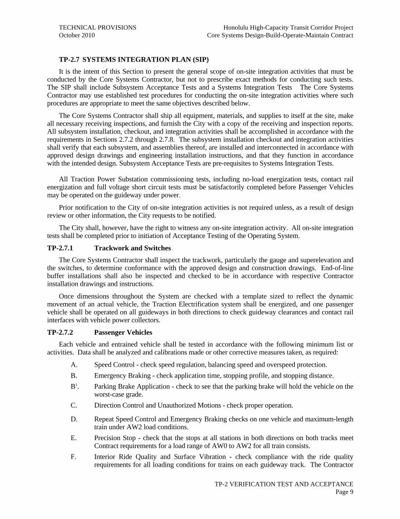


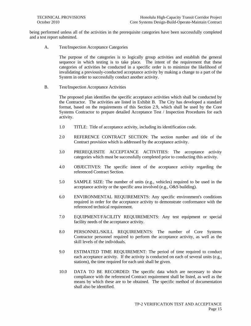


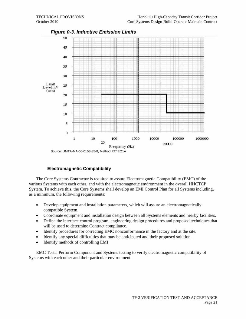


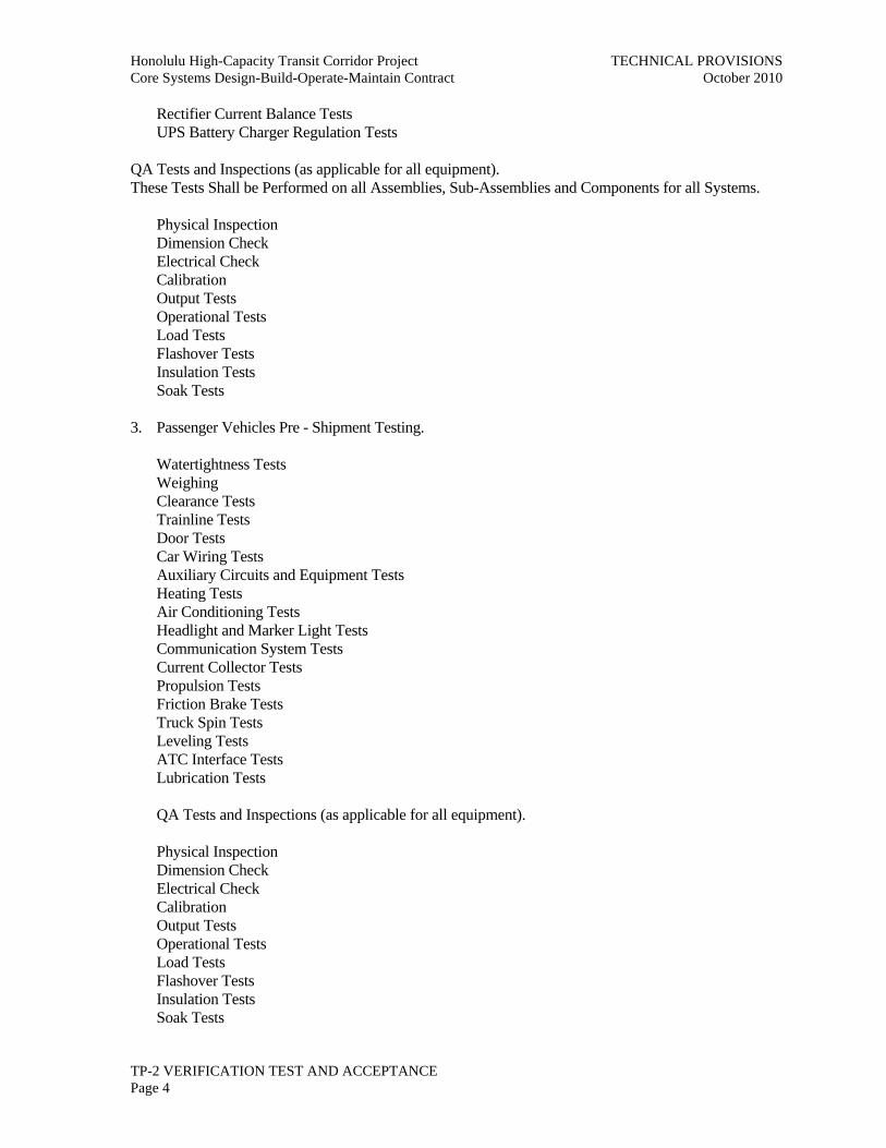
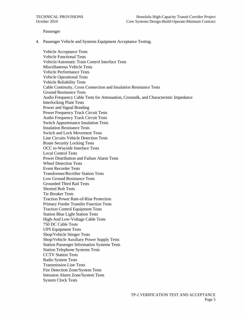
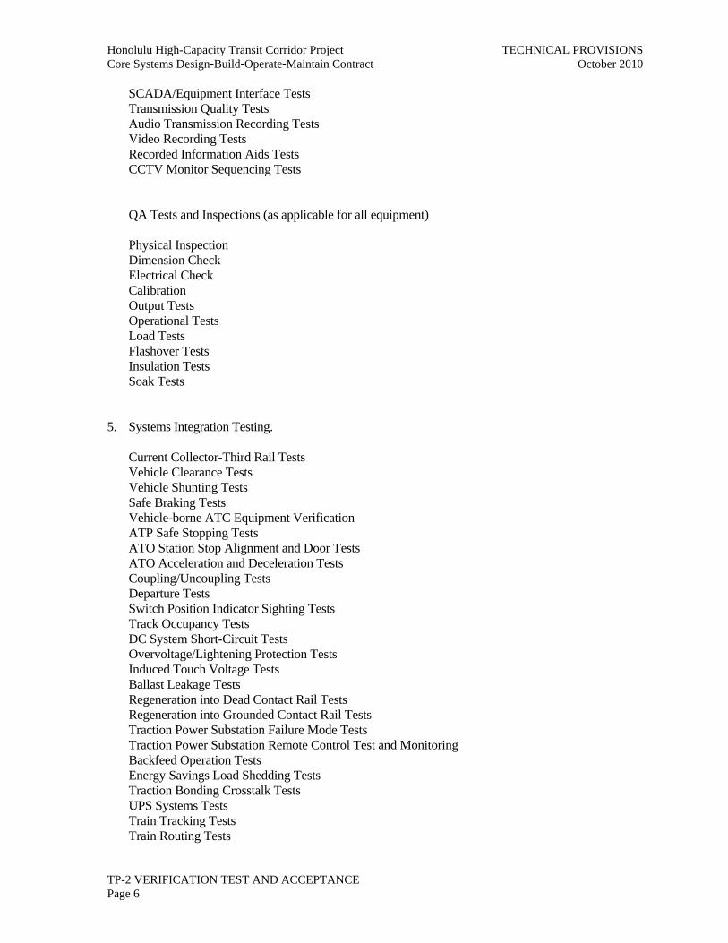


![[PPT]ALOHA FROM HAWAIIekladata.com/T87xXLe0Y72JoKgvTgg575PI2tM/Hawaiil.pps · Web view* HONOLULU - HARBOUR HONOLULU - AIRPORT HONOLULU IOLANI PALACE - HONOLULU ROYAL GUARD KAMEHAMEHA](https://static.documents.pub/doc/80x56/5af655b67f8b9a5b1e8effcd/pptaloha-from-view-honolulu-harbour-honolulu-airport-honolulu-iolani-palace.jpg)


