47
TPC Capacitors For Power Electronics Medium Power Capacitors A KYOCERA GROUP COMPANY

TPCCapacitors For Power ElectronicsMedium Power Capacitors
A KYOCERA GROUP COMPANY

1
ContentsCapacitors for Power Electronics
MEDIUM POWER FILM CAPACITORS
DC FILTERING
FFB . . . . . . . . . . . . . . . . . . . . . . . . . . . . . . . . . . . . . . . . . . . . . . . . . . . . . . . . . . . . . . . . . . . . . . . . . . . . . . 4-9
FFV3 . . . . . . . . . . . . . . . . . . . . . . . . . . . . . . . . . . . . . . . . . . . . . . . . . . . . . . . . . . . . . . . . . . . . . . . . . . . 10-12
FFVE/FFVI . . . . . . . . . . . . . . . . . . . . . . . . . . . . . . . . . . . . . . . . . . . . . . . . . . . . . . . . . . . . . . . . . . . . . . . 13-15
FFLI/FFLT . . . . . . . . . . . . . . . . . . . . . . . . . . . . . . . . . . . . . . . . . . . . . . . . . . . . . . . . . . . . . . . . . . . . . . . 16-17
FFLC/FFLP . . . . . . . . . . . . . . . . . . . . . . . . . . . . . . . . . . . . . . . . . . . . . . . . . . . . . . . . . . . . . . . . . . . . . . 18-19
FSG . . . . . . . . . . . . . . . . . . . . . . . . . . . . . . . . . . . . . . . . . . . . . . . . . . . . . . . . . . . . . . . . . . . . . . . . . . . 20-21
FSM . . . . . . . . . . . . . . . . . . . . . . . . . . . . . . . . . . . . . . . . . . . . . . . . . . . . . . . . . . . . . . . . . . . . . . . . . . . 22-23
DC PROTECTION
FSB . . . . . . . . . . . . . . . . . . . . . . . . . . . . . . . . . . . . . . . . . . . . . . . . . . . . . . . . . . . . . . . . . . . . . . . . . . . 24-26
FPX . . . . . . . . . . . . . . . . . . . . . . . . . . . . . . . . . . . . . . . . . . . . . . . . . . . . . . . . . . . . . . . . . . . . . . . . . . . 27-30
FPG . . . . . . . . . . . . . . . . . . . . . . . . . . . . . . . . . . . . . . . . . . . . . . . . . . . . . . . . . . . . . . . . . . . . . . . . . . . . 31-34
TUNING
FAV . . . . . . . . . . . . . . . . . . . . . . . . . . . . . . . . . . . . . . . . . . . . . . . . . . . . . . . . . . . . . . . . . . . . . . . . . . . . 35-36
FAI . . . . . . . . . . . . . . . . . . . . . . . . . . . . . . . . . . . . . . . . . . . . . . . . . . . . . . . . . . . . . . . . . . . . . . . . . . . . 37-44
In 1979, TPC (formerly LCC, then THOMSON-CSF PASSIVE COMPONENTS) developed theCONTROLLED SELF-HEALING technology for medium power capacitors.In 1988, TPC further evolved the CONTROLLED SELF-HEALING technology for use in impregnatedand non-impregnated DC filtering capacitor (TFM or TRAFIM, IFM, FFL, FFV and other series).These capacitors made great advances over previous technologies by combining the benefits of theControlled Self-Healing process and superior energy densities, making it one of the most compactcapacitors on the market for 1/2 CV2.TPC produces both dry-wound and impregnated capacitors for medium voltage filtering, covering the whole spectrum from 75Vdc to 3kVdc.With CONTROLLED SELF-HEALING, the capacitance is divided into several million elementary capacitor elements protected by “fuse gates”. Weak points of the dielectric are insulated and the capacitor continues functioning normally without any short circuit or explosion.The capacitor acts like a battery. It “consumes” a certain amount of the capacitance through the gradualbreakdown of the individual capacitance cells. Over the operating life of the capacitor, the capacitancegradually decreases. At the end of the capacitor’s life, the nominal capacitance will decrease down toeither 2%, 5% or can be determined per customer requirements.
NOTICE: Specifications are subject to change without notice. Contact your nearest AVX Sales Office for the latest specifications. All statements,information and data given herein are believed to be accurate and reliable, but are presented without guarantee, warranty, or responsibility ofany kind, expressed or implied. Statements or suggestions concerning possible use of our products are made without representation or warrantythat any such use is free of patent infringement and are not recommendations to infringe any patent. The user should not assume that all safetymeasures are indicated or that other measures may not be required. Specifications are typical and may not apply to all applications.

2
DC
FILT
ER
ING
Medium Power Film CapacitorsGeneral Description
DC FILTERINGThe series uses a dry-wound (non-oil-filled) segmented metallized polypropylene or polyester dielectric, which features the controlled self-healing process, specially treatedto have a very high dielectric strength in operating conditionsup to 85°C, and up to 100°C for the FFB series. For more information on how segmented metallized films and controlled self-healing works see a complete presentation.
AN ALTERNATIVE TO ELECTROLYTICSFF series capacitors can be a very interesting alternative to electrolytic capacitors, because they can withstand muchhigher levels of surge voltage, very high rms currents andoffer longer lifetimes (see section on lifetime as well as deter-mination tables).
APPLICATIONSThe FF series capacitors are specifically designed for DC filtering and low reactive power. Main applications are: powersupplies, motors, drives, electric utilities, induction heating,people movers, tramways, metro systems, unit supportedpower supplies, etc.
STANDARDS
IEC 1071-1, IEC 1071-2: Power electronic capacitorsIEC 384-1: PET Electronic CapacitorIEC 68-1: Environmental testing
IEC 77: Rules for electric traction equipmentUL 94: Fire requirements
NF F 16-101NF F 16-102: Fire and smoke requirements
WORKING TEMPERATURE-40°C to +85°C (up to +100°C for FFB series)
LIFETIME EXPECTANCYOne unique feature of the segmented metallized technologyis how the capacitor acts at the end of its lifetime. While elec-trolytic capacitors present a strong risk of short-circuit andconsequently explosion, this film capacitor simply experi-ences a loss of capacitance of about 5%, with no risk ofexplosion. The capacitor gradually loses capacitance over its lifetime (like a battery), and eventually becomes anopen circuit.Lifetime, therefore, as it is defined here, is a function of several elements:• Decrease in capacitance limit (-5% in the example above)• Average applied voltage (expressed as a ratio vs nominal
rated voltage)• Average hot spot temperatureBy changing any of these parameters we can change thedefined “lifetime” of the capacitor. This lifetime is theoretical,however as the capacitor continues to function even beyondthe preestablished limit on capacitance decrease. See life-time expectancy tables as part of this catalog to help in thisdetermination.

3
DC
FIL
TE
RIN
G
CAPACITANCE FOR POLYESTER DIELECTRICCapacitance of polyester capacitors is a function of temperature and frequency (see the curves).
TANGENT OF LOSS ANGLE (TANδ0)FOR POLYPROPYLENE DIELECTRICPolypropylene has a constant dielectric loss factor of 2x10⁻⁴
irrespective of temperature and frequency (up to 1 MHz).
HOT SPOT CALCULATIONCalculate the maximum operating (hot spot) temperature inthe following manner:The loss factor of the capacitor is made up of the sum of twocomponents. The first represents electrical losses (see thecurve polyester losses) and the second represents Jouleeffect in the connections and foil. For detail formulas refer toindustrial products.
3
2
1
0
-1
-2
-3
-40.05 0.1 1 10
T: Room Temperature
∆C/C
(%)
100 F (kHz)
100kHz10kHz
1kHz100Hz
5
0
-5
-55 0 50 85T (°C)
∆C/C
(%)
0
50
100
150
200
250
300
-40 -20 0 20 40 60 80 100
1kHz
10kHz
100kHz
1MHz
frequency
Loss factor in Polyester Dielectric
Hot spot temperature (°C)
Tg
δ (
10-4
)O
Medium Power Film CapacitorsGeneral Description
TANGENT OF LOSS ANGLE (TANδ0) FOR POLYESTER DIELECTRICDielectric loss factor of polyester is a function of temperature and frequency (see the curves).

Medium Power Film CapacitorsFFB
The FFB series uses a non-impregnated metallizedpolypropylene or polyester dielectric with the controlled self-healing process, specially treated to have a very highdielectric strength in operating conditions up to 100°C. The FFB has been designed for printed circuit board mount-ing. Furthermore, their performances allow to be a very inter-esting alternative to electrolytic technology because theycan withstand much higher levels of surge voltage.
APPLICATIONSThe FFB capacitor is particularly designed for DC filtering,low reactive power.
GENERAL CHARACTERISTICSClimatic category 55/100/56 (IEC 68)Test voltage between terminals @ 25°C
1.5 x Vndc
4
DC
FILT
ER
ING
STANDARDSIEC 1071-1, IEC 1071-2: Power electronic capacitors
IEC 60 384-16: Fixed metallized polypropylenefilm dielectric DC capacitors
IEC 60 384-16-1: Fixed metallized polypropylenefilm dielectric DC capacitorsAssessment level E
IEC 60 384-17: Fixed metallized polypropylene film dielectric AC and pulsecapacitors
IEC 60 384-17-1: Fixed metallized polypropylenefilm dielectric AC and pulsecapacitorsAssessment level E
WORKING TEMPERATURE(according to the power to be dissipated) -55°C to +100°C
LIFETIME EXPECTANCYOne unique feature of this technology (as opposed to elec-trolytics) is how the capacitor reacts at the end of its lifetime.Whereas, with an electrolytic, there is a strong risk of explo-sion of the case. However, with our line of film capacitors, thecapacitor will simply experience at the end of life a loss ofcapacitance of about 5%, with no risk of explosion.Please note that this is theoretical, however, as the capacitorcontinues to be functional even after this 5% decrease.
HOT SPOT TEMPERATURE CALCULATIONYou can calculate the maximum operating (hot spot) temper-ature of this capacitor in the following manner:The loss factor of the capacitor is made up of the sum of twocomponents. The first represents electrical losses in thedielectric and the second component represents Joule effectin the connection and foils (Rs.C.2 π f).For all applications, the temperature in the hot spot capaci-tor must be lower than 100°C.
θhot spot = θambient + [tgδ0.Q+Rs.(Irms)2].Rth
With:Q : Reactive power in VarRS in OhmIrms in AmpereRth : Rth ambient / hot spot in °C/Wtg δ0
.(10-4) is the tangent of loss angle (see tan δ0 page 3)
PACKAGINGSelf-extinguishing plastic case (V0 = in accordance with UL 94)filled thermosetting resin.Self-extinguishing thermosetting resin (V0 = in accordance withUL 94; M2F1 = in accordance with NF F 16-101).

5
DC
FIL
TE
RIN
G
Medium Power Film CapacitorsFFB
Length
Height
LS 0.4 min(0.015 min) 5.5 ±1
(0.216 ±0.039)
Width
Ø Lead
General Tolerance: ±0.5mm (0.020)
32 (1.259)
37 (1.456)
0.4 min(0.015 min)
5.5 ±1 (0.216 ±0.039)
1.2 ±0.1(0.047 ±0.003)
12.7 ±0.5(0.5 ±0.020)
Width
Ep 0.6 (0.023)
General Tolerance: ±0.5mm (0.020)
22 (0.866)
27.5 ±0.5
(1.082 ±0.019)
DIMENSIONS: millimeters (inches)Box Kind Length Width Height Dimensions LS
mm ±0.40 mm ±0.40 mm ±0.30 lead mm mm ±0.40(inches) (inches) (inches) (inches) (inches)
PO 31.1 (1.230) 13.0 (0.051) 22.4 (0.880) Ø 0.80 (0.031) 27.5 (1.083)
18 31.1 (1.230) 14.6 (0.580) 25.7 (1.010) Ø 0.80 (0.031) 27.5 (1.083)
19 31.1 (1.230) 17.3 (0.068) 29.8 (1.170) Ø 0.80 (0.031) 27.5 (1.083)
26 31.1 (1.230) 20.8 (0.820) 31.3 (1.230) Ø 1.00 (0.039) 27.5 (1.083)R68
2 Terminals 32.0 (1.260) 22.0 (0.870) 37.0 (1.460) Ø 1.00 (0.039) 27.5 (1.083)Solution
R681.20 x 0.604 Terminals 32.0 (1.260) 22.0 (0.870) 37.0 (1.460)
(0.047 x 0.023)27.5 (1.083)
Solution
BOX KIND: P0; 18; 19; 26; R68
2 TERMINALS SOLUTION
BOX KIND: R68
4 TERMINALS SOLUTION
GENERAL DESCRIPTION

6
DC
FILT
ER
ING
Medium Power Film CapacitorsFFB
Capacitance range Cn 6.2µF to 110µFTolerance on Cn ±10%Rated DC voltage Vndc 75 to 400 VDielectric polyester
ELECTRICAL CHARACTERISTICS
DC FILTERING FOR LOW VOLTAGE
HOT SPOT CALCULATIONθhot spot = θambient + (Pd + Pt) x Rth
with Pd (Dielectric losses) = Q x tgδ0Q x tgδ0 ⇒ [ 1⁄2 x Cn x (Vpeak to peak)2 x f ] x tgδ0(see tgδ0 for polyester dielectric page 3)
Pt (Thermal losses) = Rs x (Irms)2
where Cn in Farad Irms in Ampere f in HertzV in Volt Rs in Ohm θ in °CRth in °C/W

7
DC
FIL
TE
RIN
G
DC FILTERING FOR LOW VOLTAGE
POLYESTER DIELECTRIC
Medium Power Film CapacitorsFFB
CapacitanceBox Kind
Irms max. RS Rth Part Number(µF) (A) (mΩ) (°C/W)
Vndc 75V Vrms max.: 45 volts33 PO 3 3 40.7 FFB14D0336K--47 18 4.3 2 33.3 FFB24D0476K--68 19 6.2 1.7 29.9 FFB34D0686K--82 26 7.4 1.6 26.7 FFB44D0826K--
110R68
10 1.4 22.9 FFB54D0117K--(2 terminals)
110R68
10 1.4 22.9 FFB54D0117KJC(4 terminals)
Vndc 100V Vrms max.: 60 volts20 PO 2.6 3 40.5 FFB14E0206K--27 18 3.5 2.5 33.3 FFB24E0276K--39 19 5 2 29.8 FFB34E0396K--47 26 6 1.7 26.6 FFB44E0476K--
68R68
9 1.4 22.8 FFB54E0686K--(2 terminals)
68R68
9 1.4 22.8 FFB54E0686KJC(4 terminals)
Vndc 300V Vrms max.: 90 volts7.5 PO 2.4 16 40.7 FFB14H0755K--11 18 3.6 11 33.5 FFB24H0116K--16 19 5.2 8 29.9 FFB34H0166K--18 26 6 7 27.1 FFB44H0186K--
27R68
9 5 22.9 FFB54H0276K--(2 terminals)
27R68
9 5 22.9 FFB54H0276KJC(4 terminals)
Vndc 400V Vrms max.: 105 volts6.2 PO 2.5 17 40.5 FFB14I0625K--7.5 18 3.1 14 33.5 FFB24I0755K--12 19 5 9 29.9 FFB34I0126K--15 26 6.2 7 26.4 FFB44I0156K--
20R68
8.2 5.5 22.8 FFB54I0206K--(2 terminals)
20R68
8.2 5.5 22.8 FFB54I0206KJC(4 terminals)
TABLE OF VALUES
50°C70°C85°C
1.5
1.3
1.1
0.9
0.710 100 1000
Lifetime Expectancy (Hours)
Vw
/Vn
10000 100000
100°C
LIFETIME EXPECTANCY vs Vw/Vn AND HOT SPOT TEMPERATURE
Vw = Working DC Voltage
Vn = Rated DC Voltage

8
DC
FILT
ER
ING
Medium Power Film CapacitorsFFB
Capacitance range Cn 1.5µF to 13µFTolerance on Cn ±10%Rated DC voltage Vndc 525 to 1100 VDielectric polypropylene
ELECTRICAL CHARACTERISTICS
DC FILTERING FOR INDUSTRIAL APPLICATIONThese capacitors have been designed principally for high and medium power DC filtering applications.
TANGENT OF LOSS ANGLE (TANδ0)FOR POLYPROPYLENE DIELECTRICPolypropylene has a constant dielectric loss factor of 2x10⁻⁴
irrespective of temperature and frequency (up to 1 MHz).
HOT SPOT TEMPERATURE CALCULATIONYou can calculate the maximum operating (hot spot) temper-ature of this capacitor in the following manner:The loss factor of the capacitor is made up of the sum of two components. The first represents electrical losses (tg δ0 = 2x10⁻⁴) and the second component represents Jouleeffect in the connection and foils, (Rs.C.2 π f).
For all applications, the temperature in the hot spot capaci-tor must be lower than 100°C. Heating calculation of hotspot capacitor:
θhot spot = θambient + [tgδ0.Q+Rs.(Irms)2].Rth
With:Q : Reactive power in VarRS in OhmIrms in AmpereRth : Rth ambient / hot spot in °C/Wtg δ0
.(10-4) is the tangent of loss angle for polypropy-lene dielectric. Polypropylene has a constant dielectric losses factor of 2x10⁻⁴ irrespective of temperature andfrequency (up to 1 MHz).

9
DC
FIL
TE
RIN
G
Medium Power Film CapacitorsFFB
CapacitanceBox Kind
Irms max. RS Rth Part Number(µF) (A) (mΩ) (°C/W)
Vndc 525V Vrms max.: 105 volts3.9 PO 5.1 30 45.7 FFB16J0395K--5.6 18 7.4 21 36.4 FFB26J0565K--8.2 19 10.9 15 32.6 FFB36J0825K--10 26 13.3 12 29.8 FFB46J0106K--
13R68
16.7 9 24.3 FFB56J0136K--(2 terminals)
13R68
16.7 9 24.3 FFB56J0136KJC(4 terminals)
Vndc 720V Vrms max.: 120 volts3.3 PO 5.0 31 45.0 FFB16A0335K--4.3 18 6.5 24 36.2 FFB26A0435K--6.2 19 9.4 17 32.7 FFB36A0625K--7.5 26 11.4 14 29.9 FFB46A0755K--
10R68
15.2 11 24.2 FFB56A0106K--(2 terminals)
10R68
15.2 11 24.2 FFB56A0106KJC(4 terminals)
Vndc 900V Vrms max.: 150 volts2 PO 3.6 41 45.7 FFB16C0205K--
2.7 18 4.9 30 36.6 FFB26C0275K--3.9 19 7.2 21 32.9 FFB36C0395K--5.1 26 9.3 16 29.7 FFB46C0515K--
6.8R68
12.5 12 24.1 FFB56C0685K--(2 terminals)
6.8R68
12.5 12 24.1 FFB56C0685KJC(4 terminals)
Vndc 1100V Vrms max.: 180 volts1.5 PO 3.3 45 45.2 FFB16L0155K--1.8 18 3.9 40 36.5 FFB26L0185K--2.4 19 5.3 28 33.4 FFB36L0245K--3 26 6.6 23 30.2 FFB46L0305K--
4.7R68
10.3 15 24.1 FFB56L0475K--(2 terminals)
4.7R68
10.3 15 24.1 FFB56L0475KJC(4 terminals)
POLYPROPYLENE DIELECTRIC
TABLE OF VALUES
DC FILTERING FOR INDUSTRIAL APPLICATION
LIFETIME EXPECTANCY vs Vw/Vn AND HOT SPOT TEMPERATURE
Vw = Working DC Voltage
Vn = Rated DC Voltage
50°C
100 1000 10000Lifetime expectancy (Hours)
Vw
/Vn
100000
1.8
1.6
1.4
1.2
1.0
0.8
0.6
70°C85°C
100°C

10
DC
FILT
ER
ING
Climatic category 40/85/56 (IEC 68)Test voltage between terminals @ 25°C 1.5 x Vndc during 10sTest voltage between terminals and case @ 25°C @ 4 kVrms @ 50 Hz during 1 min.
GENERAL CHARACTERISTICS
Medium Power Film CapacitorsFFV3 General Description
The series uses a non-impregnated metallized polypropyleneor polyester dielectric, with the controlled self-healing process,specially treated to have a very high dielectric strength in oper-ating conditions up to 85°C. The FFV3 has been designed for printed circuit board mounting.
DC FILTERING
APPLICATIONSThe FFV3 capacitors are particularly designed for DC filter-ing, low reactive power.
PACKAGINGSelf-extinguishing plastic case (V0 = in accordance with UL 94)filled thermosetting resin.Self-extinguishing thermosetting resin (V0 = in accordance withUL 94; M2F1 = in accordance with NF F 16-101).
LIFETIME EXPECTANCYOne unique feature of this technology (as opposed to elec-trolytics) is how the capacitor reacts at the end of its lifetime.Whereas, with an electrolytic, there is a strong risk of explo-sion of the case. However, with our line of film capacitors, thecapacitor will simply experience at the end of life a loss ofcapacitance of about 5%, with no risk of explosion.Please note that this is theoretical, however, as the capacitorcontinues to be functional even after this 5% decrease.
STANDARDSIEC 1071-1, IEC 1071-2: Power electronic capacitors
IEC 60 384-16: Fixed metallized polypropylenefilm dielectric DC capacitors
IEC 60 384-16-1: Fixed metallized polypropylenefilm dielectric DC capacitorsAssessment level E
IEC 60 384-17: Fixed metallized polypropylene film dielectric AC and pulsecapacitors
IEC 60 384-17-1: Fixed metallized polypropylenefilm dielectric AC and pulsecapacitorsAssessment level E
IEC 384-2: Fixed metallized polyestercapacitors
2
4
1
3
1.2 (0.048) B
30 (1.181)
25 (0.984)
1.2 (0.047)±0.1 (0.004)
4.5 (0.178)±1 (0.040)
B
A
General tolerance: ±0.5 (±0.020)Dimensions: millimeters (inches)
1 2
3 4
0.6 (0.024) A
Plastic Case
40 (1.575)
40 (1.575)
16 (0.630)
36 (1.418)
0.8 (0.032)±0.1 (0.004)

11
DC
FIL
TE
RIN
G
HOT SPOT CALCULATION
DC FILTERING
POLYESTER DIELECTRIC
Medium Power Film CapacitorsFFV3 for Low Voltage Applications
VW
/VN 1.5
1.4
1.3
1.2
1.1
0.9
0.810
1
100 1000 10000 100000Lifetime Expectancy (hours)
70°C60°C
80°C
85°C
50°C
Capacitance Irms max. (I2t)10 shots (I2t)1000 shots Rs Rth Part Number(µF) (A) (A2s) (A2s) (mΩ) (°C/W)Vndc = 75 V Vrms = 45 v max
130 23 370 37 0.56 5.60 FFV34D0137K--160 28 560 56 0.47 5.00 FFV34D0167K--
Vndc = 100 V Vrms = 60 v max80 19 250 25 0.67 6.16 FFV34E0806K--
100 24 390 39 0.55 5.42 FFV34E0107K--Vndc = 160 V Vrms = 75 v max
55 17 180 18 0.77 6.56 FFV34F0556K--65 20 260 26 0.66 5.97 FFV34F0656K--
Vndc = 300 V Vrms = 90 v max40 20 150 15 2.80 9.58 FFV34H0406K--50 26 230 23 2.25 8.46 FFV34H0506K--
Vndc = 400 V Vrms = 105 v max30 17 110 11 2.93 9.92 FFV34I0306K--40 23 200 20 2.21 8.41 FFV34I0406K--
LIFETIME EXPECTANCY
Capacitance range Cn 30µF to 160µFTolerance on Cn ±10%Rated DC voltage Vndc 75 to 400 VDielectric polyester
ELECTRICAL CHARACTERISTICS
θhot spot = θambient + (Pd + Pt) x (Rth + 7.4)θhot spot = θcase + (Pd + Pt) x Rth
with Pd (Dielectric losses) = Q x tgδ0⇒ [ 1⁄2 x Cn x (Vpeak to peak)2 x f ] x tgδ0(see tgδ0 curves page 3)
Pt (Thermal losses) = Rs x (Irms)2
where Cn in Farad Irms in Ampere f in HertzV in Volt Rs in Ohm θ in °CRth in °C/W Rth : Rth case/hot spot in °C/W

12
DC
FILT
ER
ING
Capacitance Irms max. (I2t)10 shots (I2t)1000 shots Rs Rth Part Number(µF) (A) (A2s) (A2s) (mΩ) (°C/W)Vndc = 500 V Vrms = 105 v max
20 27 3200 320 5.88 3.53 FFV36J0206K--25 33 5000 500 4.72 3.14 FFV36J0256K--
Vndc = 700 V Vrms = 120 v max14 21 2000 200 7.34 3.73 FFV36A0146K--20 30 4200 420 5.15 3.05 FFV36A0206K--
Vndc = 900 V Vrms = 150 v max10 19 1600 160 8.21 3.37 FFV36C0106K--13 25 2800 280 6.33 2.91 FFV36C0136K--
Vndc = 1100 V Vrms = 180 v max6 13 800 80 11.4 3.71 FFV36L0605K--9 20 1900 190 7.61 2.92 FFV36L0905K--
Medium Power Film CapacitorsFFV3 DC for Medium and High Voltage Applications
Capacitance range Cn 6µF to 25µFTolerance on Cn ±10%Rated DC voltage Vndc 500 to 1100 VDielectric polypropylene
ELECTRICAL CHARACTERISTICS
VW
/VN
LIFETIME EXPECTANCY
DC FILTERING
POLYPROPYLENE DIELECTRIC
HOT SPOT CALCULATIONθhot spot = θambient + (Pd + Pt) x (Rth + 7.4)θhot spot = θcase + (Pd + Pt) x Rth
with Pd (Dielectric losses) = Q x tgδ0⇒ [1⁄2 x Cn x (Vpeak to peak)2 x f ] x (2 x 10⁻⁴)
Pt (Thermal losses) = Rs x (Irms)2
where Cn in Farad Irms in Ampere f in HertzV in Volt Rs in Ohm θ in °CRth in °C/W Rth : Rth case/hot spot in °C/W

13
DC
FIL
TE
RIN
G
Medium Power Film CapacitorsFFVE/FFVI/FFVA
PACKAGINGSelf-extinguishing plastic case (V0 = inaccordance with UL 94) filled thermosettingresin.
Self-extinguishing thermosetting resin (V0= in accordance with UL 94; M2F1 = inaccordance with NF F 16-101).
TPC
06 (0.024)
101 (3.98)
22 (0.866)
Max Torque M8: 10 (0.394) N.m
Ø5.5 (0.217)
Tightening Torque3 (0.118)N.m max
Ø16 (0.63)min
Ø84max
Ø20 (0.787)±1 (0.039)
Plastic Case
Resin
Tinned Output
*Mounting with Thermal Interface Grease Dimensions: millimeters (inches) General Tolerance: ±0.5 (0.020)
71.7 (2.82)
Ø84 (3.31)max45 (1.77)
±1 (0.039)
H ±1 (0.039)
20 (0.788)±1 (0.039)
(H+6)±2(H+0.237)
±0.079
M8 (0.315)
1 (0.039)
5 (0.197)
DESIGN - Also available with threadedfemale connections - useFFVA female connectorsM5 x 7.5mm
DC FILTERING
The FFVE for low voltage DC filtering are polyester dielectric capacitors.
Working temperature -40°C to +85°C (according to the power to be dissipated)Capacitance range 12µF to 400µFCapacitance tolerance ±10%Rated DC voltage 300 to 1100 VTest voltage between terminals @ 25°C 1.5 x Vndc 10s (1.25 Vndc – 10s for FFVI)Insulation voltage betweenshorted terminals and earth 4 kVrms
The FFV capacitor is specifically designed for DC filtering, low reactive power.The series uses a non-impregnated metallized polypropylene or polyester dielectric, whichfeatures a controlled self-healing process, specially treated to have a very high dielectricstrength in operating conditions up to 85°C.The FFV special design gives this series a very low level of stray inductance (18 nH to 40 nH).Furthermore, the performance levels of the FFVE capacitor makes them a very interestingalternative to electrolytic technology, because they can withstand much higher levels ofsurge voltage, very high rms current ratings, and longer lifetimes.
Rs(f) = (Rs-a) + k aH=34: a 0.20H=40: a 0.21H=51: a 0.23H=64: a 0.24
3.5
3.0
2.5
2.0
1.5
1.01 10
Frequency (kHz)
K
100 1000
Rs(f) vs FREQUENCYFor frequency higher than 1 kHz
use following curve

14
DC
FILT
ER
ING
Medium Power Film CapacitorsFFVE/FFVI/FFVA
CapacitanceHeight
Irms max. Ls max. Rs RthPart Number*(µF) (A) (nH) (mΩ) (°C/W)
Vndc 300 volts180 34 (1.339) 100 18 0.8 4.7 FFVE4H0187K--195 34 (1.339) 100 18 0.8 4.4 FFVE4H1956K--250 40 (1.575) 100 25 0.6 5.2 FFVE4H0257K--350 51 (2.008) 100 32 0.8 7.2 FFVE4H0357K--400 51 (2.008) 110 32 0.8 7.1 FFVE4H0407K--
Vndc 400 volts100 34 (1.339) 80 18 0.7 4.7 FFVE4I0107K--120 34 (1.339) 100 18 0.6 4.1 FFVE4I0127K--150 40 (1.575) 100 25 0.7 5.0 FFVE4I0157K--180 51 (2.008) 80 32 1.0 8.5 FFVE4I0187K--220 51 (2.008) 100 32 0.9 7.2 FFVE4I0227K--
POLYESTER DIELECTRIC Dimensions: millimeters (inches)
*Change FFVE to FFVA for female connectors M5 x 7.5mm
*Change FFVE to FFVA for female connectors M5 x 7.5mm
LIFETIME EXPECTANCY FOR FFVE
Vu: Operating or working voltage.
CapacitanceHeight
Irms max. Ls max. Rs RthPart Number*(µF) (A) (nH) (mΩ) (°C/W)
Vndc 600 volts25 34 (1.339) 90 18 0.7 4.3 FFVE6K0256K--
100 40 (1.575) 100 25 0.6 4.8 FFVE6K0107K--150 51 (2.008) 110 32 0.9 6.9 FFVE6K0157K--220 64 (2.520) 100 40 1.0 8.4 FFVE6K0227K--
Vndc 800 volts66 40 (1.575) 100 25 0.7 4.7 FFVE6B0666K--
100 51 (2.008) 90 32 1.0 6.7 FFVE6B0107K--140 64 (2.520) 100 40 1.3 8.4 FFVE6B0147K--
Vndc 900 volts12 34 (1.339) 70 18 0.9 4.4 FFVE6C0126K--38 34 (1.339) 100 18 0.7 3.9 FFVE6C0386K--47 40 (1.575) 100 25 0.8 4.6 FFVE6C0476K--70 51 (2.008) 100 32 1.2 6.7 FFVE6C0706K--
100 64 (2.520) 90 40 1.1 8.2 FFVE6C0107K--
POLYPROPYLENE DIELECTRIC
0.6
0.8
1.0
1.2
1.4
1.6
1.8
1 10 100 1000 10000 100000 1000000
Lifetime expectancy(hours )
50°C60°C70°C80°C85°C
POLYPROPYLENE DIELECTRIC
Hot spot temperature
Vu/V
ndc
0.8
0.9
1.0
1.1
1.2
1.3
1.4
1.5
10 100 1000 10000 100000 1000000
50°C60°C70°C80°C85°C
Lifetime expectancy(hours )
POLYESTER DIELECTRICHot spot temperature
Vu/V
ndc
Vu: Operating or working voltage.
LIFETIME EXPECTANCY FOR FFVE
15
DC
FIL
TE
RIN
G
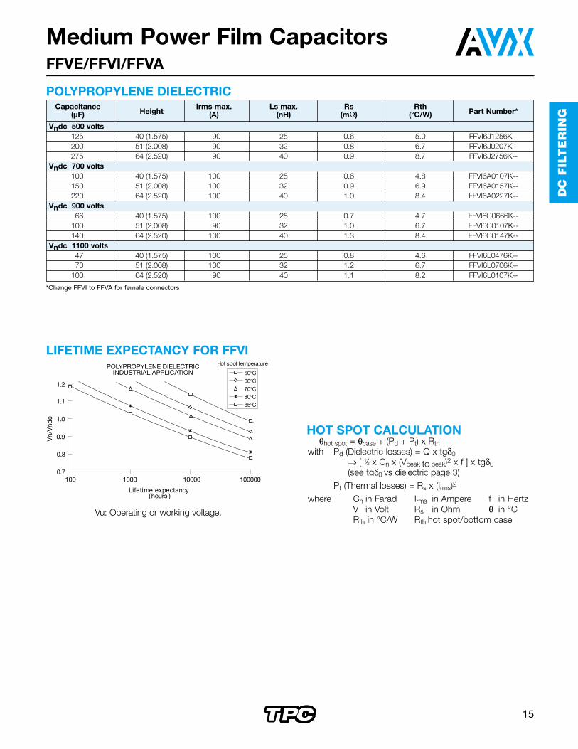
LIFETIME EXPECTANCY FOR FFVI
Vu: Operating or working voltage.
POLYPROPYLENE DIELECTRICCapacitance
HeightIrms max. Ls max. Rs Rth
Part Number*(µF) (A) (nH) (mΩ) (°C/W)
Vndc 500 volts125 40 (1.575) 90 25 0.6 5.0 FFVI6J1256K--200 51 (2.008) 90 32 0.8 6.7 FFVI6J0207K--275 64 (2.520) 90 40 0.9 8.7 FFVI6J2756K--
Vndc 700 volts100 40 (1.575) 100 25 0.6 4.8 FFVI6A0107K--150 51 (2.008) 100 32 0.9 6.9 FFVI6A0157K--220 64 (2.520) 100 40 1.0 8.4 FFVI6A0227K--
Vndc 900 volts66 40 (1.575) 100 25 0.7 4.7 FFVI6C0666K--
100 51 (2.008) 90 32 1.0 6.7 FFVI6C0107K--140 64 (2.520) 100 40 1.3 8.4 FFVI6C0147K--
Vndc 1100 volts47 40 (1.575) 100 25 0.8 4.6 FFVI6L0476K--70 51 (2.008) 100 32 1.2 6.7 FFVI6L0706K--
100 64 (2.520) 90 40 1.1 8.2 FFVI6L0107K--
50°C60°C70°C80°C85°C
0.7
0.8
0.9
1.0
1.1
1.2
100 1000 10000 100000
Lifetime expectancy(hours )
POLYPROPYLENE DIELECTRICINDUSTRIAL APPLICATION
Hot spot temperature
Vn/
Vnd
c
HOT SPOT CALCULATIONθhot spot = θcase + (Pd + Pt) x Rth
with Pd (Dielectric losses) = Q x tgδ0⇒ [ 1⁄2 x Cn x (Vpeak to peak)2 x f ] x tgδ0(see tgδ0 vs dielectric page 3)
Pt (Thermal losses) = Rs x (Irms)2
where Cn in Farad Irms in Ampere f in HertzV in Volt Rs in Ohm θ in °CRth in °C/W Rth hot spot/bottom case
Medium Power Film CapacitorsFFVE/FFVI/FFVA
*Change FFVI to FFVA for female connectors

16
DC
FILT
ER
ING
Medium Power Film CapacitorsFFLI Design
PACKAGING - also available with female connectionsCylindrical resin-filled aluminum case.
DC FILTERING
20 (0.787) ±1 (0.039)
16 (0.630) mini
Aluminum Case
Tinned Output
Resin
Max Torque 10Nm
92 (3.622) Max.
45 (1.772)±1 (0.039)
M8 (0.315)1 (0.039)
5 (0.197)
20 (0.787)±1 (0.039)
H ±2(0.079)
16 (0.630)±1 (0.039)M12 (0.472)
Capacitance range Cn 160µF to 390µFTolerance on Cn ±10%Rated DC voltage Vndc 1000 to 1200 VMaximum rms current Irms max 60 ArmsStray inductance Ls 60 nH to 85 nHTest voltage between terminals @ 25°C 1.5 Vndc 10 sTest voltage between terminals and case @25°C 4 kVrms @ 50 Hz during 1 min.
ELECTRICAL CHARACTERISTICS
HOT SPOT CALCULATION
LIFETIME EXPECTANCY
Vu: Operating or working voltage.
50°C1.60
Hotspot Temperature (°C)
1.40
1.20
1.00
0.8010 100 1000
Lifetime Expectancy (Hours)
Vu/V
n
10000 100000 1000000
70°C85°C θhot spot = θambient + (Pd + Pt) x Rth
with Pd (Dielectric losses) = Q x tgδ0⇒ [ 1⁄2 x Cn x (Vpeak to peak)2 x f ] x (2 x 10⁻⁴)
Pt (Thermal losses) = Rs x (Irms)2
where Cn in Farad Irms in Ampere f in HertzV in Volt Rs in Ohm θ in °CRth in °C/W
CapacitanceHeight
Irms Ls Rs Rth Weight Part(µF) (A) (nH) (mΩ) (°C/W) (kg) Number
Vndc = 1000 V390 145 (5.709) 60 85 5.2 2.4 1.2 FFLI6L0397K--230 97 (3.819) 60 60 3.5 3.1 0.8 FFLI6L0237K--
Vndc = 1200 V270 145 (5.709) 60 85 6.1 2.4 1.2 FFLI6U0277K--160 97 (3.819) 60 60 4.1 3.1 0.8 FFLI6U0167K--
POLYPROPYLENE DIELECTRIC mm (inches) GENERAL CHARACTERISTICSMaximum overvoltage (Vs): Vs = 1.8 VndcVoltages and overvoltages withstanding for 100,000hours at Vndc and 50°C hot spot temperature:
Voltage Value Duration
Vdc = 1.67 x Vndc ≤ 100ms_1 time per day
+Vdc = 1.5 x Vndc 5 min._1 time per day
+Vdc = 1.3 x Vndc 2.5 hours_1 time per day
+Vdc = 1.1 x Vndc 40% of the 0n-load duration
+Vdo = Vndc 50% of the 0n-load duration
Sum 100,000 hours

17
DC
FIL
TE
RIN
G
VW
/VN
CapacitanceHeight
Irms Ls Rs Rth Weight Part(µF) (A) (nH) (mΩ) (°C/W) (kg) Number
Vndc = 600 V600 145 (5.709) 40 85 2.7 2.4 1.2 FFLT6K0607K--350 97 (3.819) 40 60 2 3.1 0.8 FFLT6K0357K--
Vndc = 750 V390 145 (5.709) 40 85 3.1 2.4 1.2 FFLT6A0397K--230 97 (3.819) 40 60 2.2 3.1 0.8 FFLT6A0237K--
Vndc = 900 V270 145 (5.709) 40 85 3.6 2.4 1.2 FFLT6C0277K--160 97 (3.819) 40 60 2.5 3.1 0.8 FFLT6C0167K--
Medium Power Film CapacitorsFFLT Design
PACKAGINGCylindrical resin-filled aluminum case.
DC FILTERING
35(1.378)
M5 (0.197)
16 (0.630)±1 (0.039)
H ±2(0.079)
M12 (0.472)
92 (3.622) Max.
Capacitance range Cn 160µF to 600µFTolerance on Cn ±10%Rated DC voltage Vndc 600 to 900 VMaximum rms current Irms max 40 ArmsStray inductance Ls 60 nH to 85 nHTest voltage between terminals @ 25°C 1.5 Vndc 10 sTest voltage between terminals and case @25°C 2.5 kVrms @ 50 Hz during 1 min.
ELECTRICAL CHARACTERISTICS
POLYPROPYLENE DIELECTRIC mm (inches)
Max. Torque 4Nm
LIFETIME EXPECTANCY
HOT SPOT CALCULATIONθhot spot = θambient + (Pd + Pt) x Rth
with Pd (Dielectric losses) = Q x tgδ0⇒ [ 1⁄2 x Cn x (Vpeak to peak)2 x f ] x (2 x 10⁻⁴)
Pt (Thermal losses) = Rs x (Irms)2
where Cn in Farad Irms in Ampere f in HertzV in Volt Rs in Ohm θ in °CRth in °C/W
STANDARDSIEC 1071-1IEC 1071-2: Power electronic capacitors
IEC 68-1: Environmental testingIEC 77: Rules for electric traction equipmentUL 94: Fire requirements
NF F 16-101NF F 16-102: Fire and smoke requirements
GENERAL CHARACTERISTICSClimatic category 40/85/56 (IEC 68)Maximum Peak value Maximum durationovervoltage
2 Vndc 100 ms 1 time per week1.5 Vndc 100 ms 1 time per day1.3 Vndc 1 min 1 time per day1.1 Vndc 1 h 1 time per day

18
DC
FILT
ER
ING
Medium Power Film CapacitorsFFLC/FFLP Design
PACKAGINGNon-painted rectangular resin filled aluminum case 4 x M10 terminals.
DC FILTERING
TPC
Max Torque 16Nm
1 2 3 4
2 4
1 3
ContactArea
33 (1.299)±1 (0.039)
M10 (0.394)
// 1.5 (0.060) A
A
* Dimension take on the contact area
M10: 15Nm (0.591)General tolerance: ±3
*65(2.559)
±0.5(0.020)
*65(2.559)
±0.5(0.020)
*65(2.559)
±0.5(0.020)
0/+1 (0/0.039)
335 (13.19)355 (13.98) ±0.50 (0.020)
5.5 (0.217) ±0.20 (0.008)
±2.00 (0.079)80 (3.150) ±2.00 (0.079)
375 (14.76)
Width
Width-10
(0.394)E
(H +7) ±2(H +0.278)
±0.079H ±1
(±0.039)
A
E/2
±0.5(0.020)
Capacitance range Cn 1120µF to 6600µF (other values available upon request)Tolerance on Cn ±10%Rated DC voltage Vndc 600 to 1100 VMaximum rms current Irms max 170 Arms to 300 ArmsStray inductance Ls 28 nH to 38 nH
ELECTRICAL CHARACTERISTICS
POLYPROPYLENE DIELECTRIC Dimensions: millimeters (inches)
CapacitanceHeight Width
Irms Ls Rs Rth WeightPart Number(µF) (A) (nH) (mΩ) (°C/W) (kg)
Vndc = 600 V6600 240 (9.449) 145 (5.709) 300 38 0.19 2.2 15.5 FFLP6K6607K--4200 170 (6.693) 145 (5.709) 200 30 0.28 3.3 11.3 FFLP6K4207K--
Vndc = 900 V*4300 240 (9.449) 145 (5.709) 300 38 0.52 1.1 15.5 FFLC6C4307K--2730 170 (6.693) 145 (5.709) 170 30 0.75 1.6 11.3 FFLC6C2737K--2530 240 (9.449) 95 (3.740) 300 35 0.36 0.8 10.3 FFLC6C2537K--1600 170 (6.693) 95 (3.740) 170 28 0.51 1.2 7.3 FFLC6C1607K--
Vndc = 1100 V**3000 240 (9.449) 145 (5.709) 300 38 0.60 1.1 15.5 FFLC6L3007K--1900 170 (6.693) 145 (5.709 170 30 0.87 1.6 11.3 FFLC6L1907K--1750 240 (9.449) 95 (3.740) 300 35 0.41 0.8 10.3 FFLC6L1757K--1120 170 (6.693) 95 (3.740) 170 28 0.59 1.2 7.3 FFLC6L1127K--
*Available at 1000 VDC upon request**Available at 1200 VDC upon request
Width E145 10095 50

19
DC
FIL
TE
RIN
G
Medium Power Film CapacitorsFFLC/FFLP Design
HOT SPOT CALCULATION
LIFETIME EXPECTANCY
VW
/VN
θhot spot = θambient + (Pd + Pt) x Rthwith Pd (Dielectric losses) = Q x tgδ0
⇒ [ 1⁄2 x Cn x (Vpeak to peak)2 x f ] x (2 x 10⁻⁴)Pt (Thermal losses) = Rs x (Irms)2
where Cn in Farad Irms in Ampere f in HertzV in Volt Rs in Ohm θ in °CRth in °C/W
STANDARDSIEC 1071-1IEC 1071-2: Power electronic capacitors
IEC 68-1: Environmental testingIEC 77: Rules for electric traction equipmentUL 94: Fire requirements
NF F 16-101NF F 16-102: Fire and smoke requirements
GENERAL CHARACTERISTICSClimatic category 40/85/56 (IEC 68)FFLC overvoltage: (Vs): Vs = 2 VndcMaximum Peak value Maximum durationovervoltage
1.67 Vndc 100 ms 1 time per week1.25 Vndc 100 ms 1 time per day1.1 Vndc 1 min 1 time per day
Test voltage between terminals @ 25°C1.5 x Vndc for 10s
Test voltage between terminals and case @ 25°C@ 4 kVrms @ 50 Hz for 1 min.

20
CL
AM
PIN
G
APPLICATIONSRecovery capacitor for G.T.O. switching (secondary snubber orclamp capacitor).High current DC filtering.Special metallization for DC voltage and high currents.
Climatic category 40/085/56Working temperature -40°C to +85°C
(according to the power to be dissipated)Capacitance range Cn 2µF to 40µFTolerance on Cn ±10%Rated DC voltage Vndc 900 to 1350 VAllowable overvoltages Vs = 1.1 Vndc – 1/3 of the time
1.3 Vndc – 1 min./day2 Vndc – 100 ms/day
DC test voltage between terminals 10s at 20°C ± 15°C
Vedc – 1.5 Vndc (IEC 1071)RMS current See table valuesImpulse current See table valuesSeries inductance Ls ≤ 10 nHTangent of loss angle Tg
ELECTRICAL CHARACTERISTICS
CLAMPING
MARKINGLogo TPC FSGCapacitance and tolerance in clearNominal voltage in clearRMS current in clearDate of manufacture (IEC coding)
TECHNOLOGYMetallized polypropylene dielectric specially treated towithstand high DC voltage stresses up to 85°C.Controlled self-healing.Internal geometry and connections specially developedfor high currents (Irms up to 80 A).No liquid impregnant.
PACKAGINGCylindrical plastic case.Outputs: threaded inserts either M6 or M8.Filled with thermosetting resin.Vibrations and shocks resistant to IEC 77.
CLAMPING
HOT SPOT CALCULATION
Medium Power Film CapacitorsFSG – Do not use for new design
θhot spot = θcase + (Pd + Pt) x Rthwith Pd (Dielectric losses) = Q x tgδ0
⇒ [ 1⁄2 x Cn x (Vpeak to peak)2 x f ] x (2 x 10⁻⁴)Pt (Thermal losses) = Rs x (Irms)2
where Cn in Farad Irms in Ampere f in HertzV in Volt Rs in Ohm θ in °CRth in °C/W
STANDARDSIEC 1071-1IEC 1071-2: Power electronic capacitors
IEC 68-1: Environmental testingIEC 77: Rules for electric traction equipmentUL 94: Fire requirements
NF F 16-101NF F 16-102: Fire and smoke requirements

21
CL
AM
PIN
G
Medium Power Film CapacitorsFSG – Do not use for new design
Diam.rms Rs I2.t RthCn Ø max.max.
(mΩ) (A2s) case/(µF) Height(A) hot spot
Part Number
(H)
Vndc 900 V
440 / 52
15 2.7 2 18 FSG66C0405K--(1.575 / 2.047)
960 / 52
30 1.4 10 8.8 FSG86C0905K--(2.362 / 2.047)
1472 / 52
50 1.1 25 5.8 FSG86C0146K--(2.835 / 2.047)
2082 / 52
70 0.9 50 4.1 FSG86C0206K--(3.228 / 2.047)
4092 / 62
80 0.9 75 4.9 FSG86C0406K--(3.622 / 2.440)
Vndc 1000 V
340 / 52
15 3.3 1.3 19 FSG66L0305K--(1.575 / 2.047)
860 / 52
30 1.4 9 9 FSG86L0805K--(2.362 / 2.047)
1272 / 52
50 1.1 20 6.4 FSG86L0126K--(2.835 / 2.047)
1682 / 52
70 1.0 35 4.6 FSG86L0166K--(3.228 / 2.047)
3292 / 62
80 0.9 60 4.7 FSG86L0326K--(3.622 / 2.440)
Vndc 1150 V
2.540 / 52
15 3.4 1.2 19 FSG66U0255K--(1.575 / 2.047)
6.560 / 52
30 1.4 8 8.5 FSG86U0655K--(2.362 / 2.047)
972 / 52
50 1.2 15.5 6.5 FSG86U0905K--(2.835 / 2.047)
1382 / 52
70 1.0 32 4.4 FSG86U0136K--(3.228 / 2.047)
2692 / 62
80 1.0 49 5.1 FSG86U0266K--(3.622 / 2.440)
Vndc 1350 V
240 / 52
15 3.6 1.1 17 FSG66V0205K--(1.575 / 2.047)
4.560 / 52
30 1.8 5.5 9 FSG86V0455K--(2.362 / 2.047)
772 / 52
50 1.4 9.5 6 FSG86V0705K--(2.835 / 2.047)
982 / 52
70 1.1 22 4.6 FSG86V0905K--(3.228 / 2.047)
1892 / 62
80 1.1 35 4.6 FSG86V0186K--(3.622 / 2.440)
TABLE OF VALUES Dimensions: millimeters (inches)
CLAMPING

22
CL
AM
PIN
G
Medium Power Film CapacitorsFSM – Do not use for new design
TECHNOLOGYMetallized polypropylene dielectric speciallytreated to withstand high DC voltagestresses up to 85°C.Controlled self-healing.Internal geometry and connections special-ly developed for high currents (Irms up to100 A).No liquid impregnant.Special metallization for DC voltage andhigh currents.
PACKAGINGSelf-extinguishing rectangular plastic case(in accordance with UL 94 VO) (12 kV/50Hz isolation).Filled with thermosetting resin.M8 outputs.Fixing in two planes.Vibrations and shocks resistant to IEC 77.Average weight 0.95 kg.
Climatic category 40/085/56Working temperature -40°C to +85°C
(according to the powerto be dissipated)
Capacitance range Cn 20µF to 54µFTolerance on Cn ±10%Rated DC voltage Vndc 750 to 1350 VAllowable overvoltages Vs = 1.1 Vndc – 1/3 of the time
1.3 Vndc – 1 min./day2 Vndc – 100 ms/day for
Vndc = ≤ 1150 V1.75 Vndc – 100 ms/day for
Vndc = 1350 VDC test voltage between 10s at 20°C ± 15°Cterminals Vedc – 1.5 Vndc (IEC 1071)RMS current Irms max. = 65 to 105 AImpulse current I2.t max. = 100 to 270 A2sTangent of loss angle Tg: see table of valuesSeries inductance Ls ≤ 25 nHThermal resistance Rth ambient/hot spot = 9.2°C/W
Rth case/hot spot = 3.3°C/W
ELECTRICAL CHARACTERISTICS
CLAMPING
MARKINGLogo TPC FSMCapacitance and tolerance in clearNominal voltage in clearRMS current in clearDate of manufacture (IEC coding)
APPLICATIONSRecovery capacitor for G.T.O. switching (secondary snubber or clamp capacitor).High current DC filtering.
CLAMPING

23
CL
AM
PIN
G
1) RECOVERY OF G.T.O. SWITCHINGENERGY
Choice of voltage:V1 ≤ Vndc
Repetitive surge:1.1 Vndc – 1/3 of the time
Non-repetitive surge:1.3 Vndc – 1 min./day
Occasional max. surge:2 Vndc – 100 ms/day for Vndc = ≤ 1150 V1.75 Vndc – 100 ms/day for Vndc = 1350 V
RMS current limits:The currents given in the tables are maximum. The thermal limits of the dielectric (85°C) must be respected.The self-heating can be calculated from the series resis-tance, Tg and the thermal resistance given in the table of values
∆Ø = P x Rth ≤ 85°C -Ø ambientRth: is given for still air with the capacitor not being
subjected to any other heat source.P = (Irms)2 x Rs + π2 x C (V1 - V2)2 x fr x 10-4
Temperature measuring point*Measurement of the case temperature (B) togetherwith the losses gives the temperature of the hot spot.
= (RthB x P) + B ≤ 85°C*Important for series/parallel operations.
ImportantDue to the modular nature of these capacitors series and parallel assemblies can be made to increase thecapacitance and/or voltage.Ensure that suitable sized connections are used so thatthe capacitors will not be overheated. The inductance of the connections must be low enough to ensure equalcurrent sharing of capacitors in parallel.For series assemblies, connect across each capacitor aresistor of valueR # 30 MΩ/C in µF(1.5 MΩ for C = 20 µF).
2) DC FILTERINGIdem paragraph 1.
Table of Values
*Function of power dissipation
Cn VndcIrms*
(I2.t) max.Tgδ
Rs(µF) (V)
maxi.*(A2s)
(fkHz)(mΩ)
References(A) (10-4)
54 750 105 270 2 + 3.4 f 1 FSM26A0546K--42 900 100 220 2 + 2.8 f 1.05 FSM26C0446K--33 1000 95 170 2 + 2.3 f 1.1 FSM26L0336K--28 1150 85 150 2 + 2 f 1.15 FSM26U0286K--20 1350 65 100 2 + 1.6 f 1.25 FSM26V0206K--
CLAMPING
Medium Power Film CapacitorsFSM – Do not use for new design
Typical application

24
PR
OT
EC
TIO
N
Medium Power Film CapacitorsFSB
Metallized polypropylene dielectric capacitor with controlledself-healing.Reinforced metallization developed for high impulse currents.Axial connections specially developed to reduce seriesinductance and to provide rigid mechanical mounting.
APPLICATIONSIGBT protectionIGBT clamping
PACKAGINGParallelipedic plastic case filled with thermosetting resin.Outputs: Thin copper plate designed for M5 or M6 screw.
Capacitance range Cn 0.47µF to 2.5µFTolerance on Cn ±10%Rated DC voltage Vndc 850 to 2000 VStray inductance ≤ 25 nHRMS current Irms max. = up to 28 A
The currents shown in the tables are maximum.It is necessary to respect the thermal limits of the dielectric 85°C see “Hot spot temperature calculation”
Insulation resistance Ri x C ≥ 30,000 sImpulse current I2.t max. = up to 1.69 A2s
Spikes or peak currents in the capacitors may cause a deterioration of thebonding between the metallization and the connections. These bonds arecapable of withstanding only a limited amount of energy for each spike. Thetable shows the maximum energy permitted in the form (I2.t), where I is inAmpere, and t is in seconds.
Note: The formula (I2.t) replaces dV/dt which is less easy to use as it is not an expression of energy (I = C.dV/dt).This type of capacitor has been designed to withstand high (I2.t) values.
Variation of capacitance with temperature ∆CC ≤ ±2% between -40 and 85°C
Climatic category 40/085/56 (IEC 68)Test voltage between terminals @ 25°C 2 x Vndc during 10sWithstanding voltage between terminals and case @ 25°C @ 3 kVrms @ 50 Hz during 1 min.
ELECTRICAL CHARACTERISTICS

25
PR
OT
EC
TIO
N
Medium Power Film CapacitorsFSB
Capacitance (I2t) Irms max. Rs Rth Part Number(µF) (A2s) (A) (mΩ) (°C/W)FSB 850V Vndc = 850V Vpeak = 1200V Vrms = 450V Vs = 1500V
2 0.99 25 3.4 19.1 FSB16B0205K--2.2 1.19 28 3.1 18.6 FSB16B0225K--2.5 1.54 28 2.7 17.8 FSB16B0255K--
FSB 1200V Vndc = 1200V Vpeak = 1600V Vrms = 560V Vs = 2000V1 1.47 25 3.6 17.2 FSB16U0105K--
1.2 1.69 26 3.4 17.5 FSB16U0125K--1.5 1 26 3.4 17.5 FSB16U0155K--
FSB 2000V Vndc = 2000V Vpeak = 2400V Vrms = 700V Vs = 2600V0.47 0.41 22 6.3 19.4 FSB16N0474K--0.56 0.62 23 5.2 17.9 FSB16N0564K--0.68 0.91 24 4.4 17.3 FSB16N0684K--
DESIGNPlastic case resin filled
Dimensions: millimeters (inches)
42.5(1.670)
45.0(1.770)52.0
+0 -1(2.047)
+0 -0.040
30.0(1.180)
47.0 ±1.00(1.850 ±0.04 )
6.00 +1 -0.5 (0.236 +0.040 -0.020)
14.0 (0.551) 17.0 (0.669)
12.0 (0.472)
17.5 +1 -0.5 (0.689 +0.040 -0.020)28.6 +1 -0.5 (1.126 +0.040 -0.020)
General Tolerances: ±0.50 mm (±0.020)
7.00 +0.5 -1.5(0.276 +0.020 -0.060)
0.80 ±0.10(0.031) ±(0.004)
6.20 ±0.20(0.244) ±(0.008)
7.00(0.276)

26
PR
OT
EC
TIO
N
Medium Power Film CapacitorsFSB
STANDARDSIEC 1071-1, IEC 1071-2: Power electronic capacitors
TANGENT OF LOSS ANGLE (TANδ0)FOR POLYPROPYLENE DIELECTRICPolypropylene has a constant dielectric loss factor of 2x10⁻⁴
irrespective of temperature and frequency (up to 1 MHz).
IGBT SNUBBER
HOT SPOT TEMPERATURE CALCULATIONθhot spot = θambient + (Pd + Pt) x Rth
with Pd (Dielectric losses) = Q x tgδ0⇒ [ 1⁄2 x Cn x (Vripple peak to peak)2 x f ] x (2 x 10⁻⁴)
Pt (Thermal losses) = Rs x (Irms)2
Rth : Rth ambient / hot spot in °C/Wwhere Cn in Farad Irms in Ampere f in Hertz
V in Volt Rs in Ohm θ in °C
Due to the design of the capacitor and its technology, thethermal impedance between the terminations and the core of the capacitor is low, it is necessary to take care that the capacitor is never overheated by use of wrongly sizedconnections.Do not use the capacitor as a heat sink.Due to the complexity of the IGBT / capacitor thermalexchanges, we recommend that thermal measurementsshall be made on the different components. We would bepleased to advise you on specific problems.
WORKING TEMPERATURE(according to the power to be dissipated) -40°C to +85°C
Ieff = Cb2U02
2jb0 e–2T
b2 + a
21
T
[bsin(2bT) – acos(2bT)]+ 1e–2T
+ –a
ab
2 + a2
1
a
b0 = ; b
= b02 – a
21LC
R2L
; a =
T = 1/fr
I
U
U0
t
t
with
With
L = stray inductance IGBT + capacitorR = serial resistance IGBT + capacitor
MARKINGTPC logoCapacitance and tolerance in clearNominal DC voltage in clearRMS current in clearDate of manufacture (IEC coding)

27
PR
OT
EC
TIO
N
Medium Power Film CapacitorsFPX
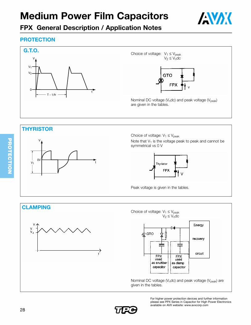
APPLICATIONSProtection of thyristors.Protection of gate turn-off thyristor (G.T.O.).Clamping (Secondary snubber).
TECHNOLOGYMetallized polypropylene dielectric capacitor with controlledself-healing.Reinforced metallization developed for high impulse currents. Axial connections specially developed to reduce seriesinductance and to provide rigid mechanical mounting.
PACKAGINGCylindrical in plastic case filled with thermosetting resin.Outputs: threaded inserts either M6 or M8.
Capacitance range Cn 0.5µF to 6µFTolerance on Cn ±5%Rated DC voltage Vndc 1000 to 3000 VPeak voltage Vpeak 1600 to 4000 VAllowable overvoltage Vs (for 10 s/day) 2000 to 4600 VStray inductance 5 to 20 nHRMS current Irms max. = up to 160 A
The currents shown in the tables are maximum.It is necessary to respect the thermal limits of the dielectric 85°C see “Hot spot temperature calculation”
Insulation resistance Ri x C ≥ 30,000 sImpulse current I2.t maxi. = up to 729 A2.s
Spikes or peak currents in the capacitors may cause a deterioration of thebonding between the metallization and the connections. These bonds arecapable of withstanding only a limited amount of energy for each spike. Thetable shows the maximum energy permitted in the form (I2.t), where I is inAmpere, and t is in seconds.
Note: The formula (I2.t) replaces dV/dt which is less easy to use as it is not an expression of energy (I = C.dV/dt).This type of capacitor has been designed to withstand high (I2.t) values.
Variation of capacitance with temperature ∆CC ≤ ±2% between -40 and 85°C
Climatic category 40/085/56 (IEC 68)Test voltage between terminals @ 25°C Vs for 10sTest voltage between terminals and case @ 25°C @ 4 kVrms @ 50 Hz for 1 min.
PROTECTION
ELECTRICAL CHARACTERISTICS
For higher power protection devices and further informationplease see PPX Series in Capacitor for High Power Electronicsavailable on AVX website: www.avxcorp.com
28
PR
OT
EC
TIO
N
Choice of voltage: V1 ≤ VpeakV2 ≤ Vndc
Nominal DC voltage (Vndc) and peak voltage (Vpeak) aregiven in the tables.
Medium Power Film CapacitorsFPX General Description / Application Notes
G.T.O. Choice of voltage: V1 ≤ Vpeak
V2 ≤ Vndc
Nominal DC voltage (Vndc) and peak voltage (Vpeak) are given in the tables.
CLAMPING
Choice of voltage: V1 ≤ Vpeak
Note that V1 is the voltage peak to peak and cannot be symmetrical vs 0 V
Peak voltage is given in the tables.
V
0
T - 1/fr
V2
V1
t
THYRISTOR
PROTECTION
V
t0V
V1
For higher power protection devices and further informationplease see PPX Series in Capacitor for High Power Electronicsavailable on AVX website: www.avxcorp.com

29
PR
OT
EC
TIO
N
* Tol: +0 / -3mm for H ≥ 118mm
Medium Power Film CapacitorsFPX Table of Values
Dimensions I2.t Irms Rs RthCnCase H* h d max. max. Part Number(µF)Type ±0.5 ±2 D ±0.1 (A2.s) (A) (mΩ) (°C/W)
(±0.020) (±0.079) max.FPX 2000 V Vndc = 1000 V Vpeak = 1600 V Vrms = 560 V Vs = 2000 V
1 Plastic case M6/6 52 (2.072) 5 (0.197) 40 (1.575) 18 (0.709) 2 15 2.4 14 FPX66N0105J--2 Plastic case M8/8 52 (2.072) 5 (0.197) 60 (2.362) 22 (0.866) 8 30 1.2 6.1 FPX86N0205J--3 Plastic case M8/8 52 (2.072) 5 (0.197) 72 (2.835) 22 (0.866) 18 45 0.9 4.5 FPX86N0305J--
3.5 Plastic case M8/8 52 (2.072) 5 (0.197) 72 (2.835) 22 (0.866) 25 50 0.85 4.5 FPX86N0355J--4 Plastic case M8/8 52 (2.072) 5 (0.197) 82 (3.228) 22 (0.866) 32 60 0.75 3.5 FPX86N0405J--5 Plastic case M8/8 52 (2.072) 5 (0.197) 82 (3.228) 22 (0.866) 50 70 0.65 2.5 FPX86N0505J--
FPX 2500 V Vndc = 1300 V Vpeak = 2000 V Vrms = 700 V Vs = 2500 V0.5 Plastic case M6/6 52 (2.072) 5 (0.197) 40 (1.575) 18 (0.709) 1 15 3 14 FPX66P0504J--1 Plastic case M8/8 52 (2.072) 5 (0.197) 60 (2.362) 22 (0.866) 3 20 2.3 10.5 FPX86P0105J--
1.5 Plastic case M8/8 52 (2.072) 5 (0.197) 60(2.362) 22 (0.866) 7 30 1.5 6.1 FPX86P0155J--2 Plastic case M8/8 52 (2.072) 5 (0.197) 72 (2.835) 22 (0.866) 12.7 40 1.1 4.5 FPX86P0205J--
2.5 Plastic case M8/8 52 (2.072) 5 (0.197) 72(2.835) 22 (0.866) 20 60 0.89 3.7 FPX86P0255J--3 Plastic case M8/8 52 (2.072) 5 (0.197) 82 (3.228) 22 (0.866) 28 60 0.85 3.2 FPX86P0305J--
3.5 Plastic case M8/8 52 (2.072) 5 (0.197) 82(3.228) 22 (0.866) 39 65 0.78 2.9 FPX86P0355J--
FPX 3500 V Vndc = 2000 V Vpeak = 2400 V Vrms = 850 V Vs = 3500 V2 Plastic case M8/8 62 (2.441) 5 (0.197) 72 (2.835) 22 (0.866) 23 41 1.24 6.1 FPX86X0205J-3 Plastic case M8/8 62 (2.441) 5 (0.197) 92 (3.622) 22 (0.866) 50 62 0.92 3.9 FPX86X0305J--
3.5 Plastic case M8/8 62 (2.441) 5 (0.197) 92 (3.622) 22 (0.866) 70 72 0.83 3.4 FPX86X0355J--4 Plastic case M8/8 62 (2.441) 5 (0.197) 92 (3.622) 22 (0.866) 85 80 0.78 3.1 FPX86X0405J--
FPX 4500 V Vndc = 2500 V Vpeak = 3200 V Vrms = 1130 V Vs = 4500 V1 Plastic case M8/8 62 (2.441) 5 (0.197) 72 (2.835) 22 (0.866) 15 38 1.4 6.2 FPX86Z0105J--2 Plastic case M8/8 62 (2.441) 5 (0.197) 92 (3.622) 22 (0.866) 70 75 0.85 3.1 FPX86Z0205J--
FPX 4600 V Vndc = 3000 V Vpeak = 4000 V Vrms = 1400 V Vss = 4600 V0.68 Plastic case M8/8 62 (2.441) 5 (0.197) 72 (2.835) 22 (0.866) 14 35 1.59 6.2 FPX86Y0684J--1.25 Plastic case M8/8 62 (2.441) 5 (0.197) 92 (3.622) 22 (0.866) 50 65 1 3.3 FPX86Y1254J--1.5 Plastic case M8/10 79 (3.110) 6 (0.236) 97 (3.819) – 32 60 1.4 8.3 FPX86Y0155J--1.7 Plastic case M8/10 79 (3.110) 6 (0.236) 97 (3.819) – 40 70 1.3 7.4 FPX86Y0175J--2 Plastic case M8/10 79 (3.110) 6 (0.236) 97 (3.819) – 56 80 1.1 6.3 FPX86Y0205J--
2.5 Plastic case M8/10 118 (4.646) 6 (0.236) 97 (3.819) – 200 130 0.8 3.3 FPX86Y0255J--2.7 Plastic case M8/10 118 (4.646) 6 (0.236) 97 (3.819) – 232 140 0.7 3.2 FPX86Y0275J--3 Plastic case M8/10 143 (5.630) 6 (0.236) 97 (3.819) – 128 100 0.9 4.4 FPX86Y0305J--
3.5 Plastic case M8/10 143 (5.630) 6 (0.236) 97 (3.819) – 170 110 0.8 4.2 FPX86Y0355J--4 Plastic case M8/10 143 (5.630) 6 (0.236) 97 (3.819) – 224 115 0.8 4.0 FPX86Y0405J--
4.5 Plastic case M8/10 163 (6.417) 6 (0.236) 97 (3.819) – 522 120 0.6 5.0 FPX86Y0455J--5 Plastic case M8/10 163 (6.417) 6 (0.236) 97 (3.819) – 600 130 0.6 5.0 FPX86Y0505J--6 Plastic case M8/10 163 (6.417) 6 (0.236) 97 (3.819) – 729 160 0.5 5.0 FPX86Y0605J--
PROTECTION Dimensions: millimeters (inches)
For higher power protection devices and further informationplease see PPX Series in Capacitor for High Power Electronicsavailable on AVX website: www.avxcorp.com

30
PR
OT
EC
TIO
N
Medium Power Film CapacitorsFPX
Dimensions: millimeters (inches)General tolerance: ±2
A
Ø4 (0.16) A
ØDmaxØd
Plastic Case or Resin Molding
ResinTinned Output
M6/6 or M8/8h ±2 (0.079)
Max Torque:10Nm (M8) 6Nm (M6)
H* ±0.5 (0.020)
h ±2 (0.079)
TPC
*H = 52 for 2000 or 2500v M6/6 M8/8*H = 62 for 3500 or 4500v M8/8
DESIGN
Plastic Case M6 / 6 or M8 / 8
PROTECTIONMARKINGLogoWithstanding surge voltageCapacitance and tolerance in clear
Nominal DC voltage in clearRMS current in clearDate of manufacture (IEC coding)
TPC
Max Torque: 10NmThe positions of the connections of each side are not indexed
Dimensions: millimeters (inches)General tolerance: ±2
A
H ≥ 79mm (3.11)
Ø4 (0.16) A
Ø28 (1.103) ±0.1 (0.004)
Plastic Case
D Max
ResinTinned Output
M8 (0.315)/10 (0.394)
M8 (0.315)/10 (0.394)
6.00 (0.236) 6.00 (0.236)
23 (0.906) ±0.50 (0.020)
Plastic Case M8 / 10
HOT SPOT TEMPERATURE CALCULATION
θhot spot = θterminals + (Pd + Pt) x Rth
withPd (Dielectric losses) = Q x tgδ0
⇒ [ 1⁄2 x Cn x (Vpeak to peak)2 x f ] x (2 x 10⁻⁴)Pt (Thermal losses) = Rs x (Irms)2
whereCn in FaradsV in Volts
Irms in AmperesRs in Ohms
f in Hertzθ in °C
Rth in °C/W
Due to the design of the capacitor and its technology, the thermal impedance between the terminations and thecore of the capacitor is low, it is necessary to take care thatthe capacitor is never overheated by use of incorrect sizedconnections.In the case where the series diodes are screwed to thecapacitor, cooling of the diodes must be taken in account.Do not use the capacitor as a heat sink.Due to the complexity of the diode/capacitor thermalexchanges, we recommend that thermal measurementsshall be made on the different components. We would bepleased to advise you on specific problems.
WORKING TEMPERATURE(according to the power to be dissipated) -40°C to +85°C
For higher power protection devices and further informationplease see PPX Series in Capacitor for High Power Electronicsavailable on AVX website: www.avxcorp.com

31
PR
OT
EC
TIO
N
Medium Power Film CapacitorsFPG - General Description
Metallized polypropylene dielectric capacitor with controlledself-healing.Reinforced metallization on margins developed for highimpulse currents.Axial connections specially developed to reduce seriesinductance and to provide rigid mechanical mounting.
APPLICATIONSProtection of gate turn-off thyristor (G.T.O.).Medium frequency tuning.
PACKAGINGCylindrical in either plastic case (preferred packaging) or aresin molding.Outputs: threaded inserts either M6 or M8.Filled with thermosetting resin.
Capacitance range Cn 0.12µF to 6µFTolerance on Cn ±5%Rated DC voltage Vndc 800 to 3000 VPeak voltage Vpeak 1200 to 4000 VAllowable overvoltage Vs (for 10 s/day) 1500 to 4600 VNominal RMS voltage Vndc 500 to 1400 VStray inductance ≈ 10 nHRMS current Irms max. = up to 80 A
The currents shown in the tables are maximum.It is necessary to respect the thermal limits of the dielectric 85°C see “Hot spot temperature calculation”
Insulation resistance Ri x C ≥ 30,000 sImpulse current I2.t max. given in the tables
Spikes or peak currents in the capacitors may cause a deterioration of thebonding between the metallization and the connections. These bonds arecapable of withstanding only a limited amount of energy for each spike. Thetable shows the maximum energy permitted in the form (I2.t), where I is inAmpere, and t is in seconds.
Note: The formula (I2.t) replaces dV/dt which is less easy to use as it is not an expression of energy (I = C.dV/dt).This type of capacitor has been designed to withstand high (I2.t) values.
Variation of capacitance with temperature ∆CC ≤ ±2% between -40 and 85°C
Climatic category 40/085/56 (IEC 68)Test voltage between terminals @ 25°C Vs during 10sTest voltage between terminals and case @ 25°C @ 4 kVrms @ 50 Hz during 1 min.
ELECTRICAL CHARACTERISTICS
PROTECTION
For higher power protection devices and further informationplease see PPX Series in Capacitor for High Power Electronicsavailable on AVX website: www.avxcorp.com

32
PR
OT
EC
TIO
N
Dimensions: millimeters (inches)General tolerance: ±2
A
Ø4 (0.16) A
ØDmaxØd
Plastic Case or Resin Molding
ResinTinned Output
M6/6 or M8/8h ±2 (0.079)
Max Torque:10Nm (M8) 6Nm (M6)
H* ±0.5 (0.020)
h ±2 (0.079)
TPC
*H = 52 for 2000 or 2500v M6/6 M8/8*H = 62 for 3500 or 4500v M8/8
Dimensions: millimeters (inches)
Medium Power Film CapacitorsFPG General Description / Application Notes
PROTECTION
APPLICATION NOTES
G.T.O. PROTECTION
Choice of voltage: V1 ≤ VpeakV2 ≤ VndcMaximum overvoltage ≤ Vs (10 s/day)
Nominal DC voltage (Vndc) and peak voltage (Vpeak) are givenin the table of values.
MARKINGLogoWithstanding surge voltageCapacitance and tolerance in clearNominal DC voltage in clearRMS current in clearDate of manufacture (IEC coding)
DESIGN
HOT SPOT TEMPERATURE CALCULATION
θhot spot = θterminals + (Pd + Pt) x Rth
withPd (Dielectric losses) = Q x tgδ0
⇒ [ 1⁄2 x Cn x (Vpeak to peak)2 x f ] x (2 x 10⁻⁴)Pt (Thermal losses) = Rs x (Irms)2
whereCn in FaradsV in Volts
Irms in AmperesRs in Ohms
f in Hertzθ in °C
Rth in °C/W
Due to the design of the capacitor and its technology, the thermal impedance between the terminations and thecore of the capacitor is low, it is necessary to take care thatthe capacitor is never overheated by use of incorrect sizedconnections.In the case where the series diodes are screwed to thecapacitor, cooling of the diodes must be taken in account.Do not use the capacitor as a heat sink.Due to the complexity of the diode/capacitor thermalexchanges, we recommend that thermal measurementsshall be made on the different components. We would bepleased to advise you on specific problems.
WORKING TEMPERATURE(according to the power to be dissipated) -40°C to +85°C
For higher power protection devices and further informationplease see PPX Series in Capacitor for High Power Electronicsavailable on AVX website: www.avxcorp.com

33
PR
OT
EC
TIO
N
Medium Power Film CapacitorsFPG Table of Values
Dimensions I2.t IrmsCnCase H* h D d max. max. Rs Rth Part Number(µF)Type ±0.5 ±2 ±0.5 (A2.s) (A) (mΩ) (°C/W)
(±0.020) (±0.079) max. (±0.020)FPG 1500 V Vndc = 800 V Vpeak = 1200 V Vrms = 500 V Vs = 1500 V
1Resin Molding 49 4.2 40 19
2 15 2.4 14 FPG66R0105J--M6/6 (1.929) (0.165) (1.575) (0.748)
1.5Resin Molding 49 4.2 55 19
4.6 20 1.6 10.5 FPG66R0155J--M6/6 (1.929) (0.165) (2.165) (0.748)
2Plastic Case 52 5 60 22
8 30 1.2 6.1 FPG86R0205J--M8/8 (2.047) (0.197) (2.362) (0.866)
3Plastic Case 52 5 72 22
18 45 0.9 4.5 FPG86R0305J--M8/8 (2.047) (0.197) (2.835) (0.866)
3.5Plastic Case 52 5 72 22
25 50 0.85 4.5 FPG86R0355J--M8/8 (2.047) (0.197) (2.835) (0.866)
4Plastic Case 52 5 82 22
32 60 0.75 3.5 FPG86R0405J--M8/8 (2.047) (0.197) (1.575) (0.866)
5Plastic Case 52 5 82 22
50 70 0.65 2.5 FPG86R0505J--M8/8 (2.047) (0.197) (3.622) (0.866)
6Resin Molding 52 5.7 92 28
73 75 0.6 2.5 FPG86R0605J--M8/8 (2.047) (0.224) (3.622) (1.102)
FPG 2000 V Vndc = 1000 V Vpeak = 1600 V Vrms = 600 V Vs = 2000 V
0.5Plastic Case 52 5 40 18
1 15 3 14 FPG66N0504J--M6/6 (2.047) (0.197) (1.575) (0.709)
1Plastic Case 52 5 60 22
3 20 2.3 10.5 FPG86N0105J--M8/8 (2.047) (0.197) (2.362) (0.866)
1.5Plastic Case 52 5 60 22
7 30 1.5 6.1 FPG86N0155J--M8/8 (2.047) (0.197) (2.362) (0.866)
2Plastic Case 52 5 72 22
12.7 40 1.1 4.5 FPG86N0205J--M8/8 (2.047) (0.197) (2.835) (0.866)
2.5Plastic Case 52 5 72 22
20 60 0.89 3.7 FPG86N0255J--M8/8 (2.047) (0.197) (2.835) (0.866)
3Plastic Case 52 5 82 22
28 60 0.85 3.2 FPG86N0305J--M8/8 (2.047) (0.197) (3.228) (0.866)
3.5Plastic Case 52 5 82 22
39 65 0.78 2.9 FPG86N0355J--M8/8 (2.047) (0.197) (3.228) (0.866)
4Resin Molding 52 5.7 92 28
50 70 0.7 2.5 FPG86N0405J--M8/8 (2.047) (0.224) (3.622) (1.102)
FPG 2500 V Vndc = 1300 V Vpeak = 2000 V Vrms = 700 V Vs = 2500 V
0.47Resin Molding 59 4.2 40 19
0.7 15 6 25 FPG66P0474J--M6/6 (2.323) (0.165) (1.575) (0.748)
1Resin Molding 59 4.2 55 19
2 18 3 13 FPG66P0105J--M6/6 (2.323) (0.165) (2.165) (0.748)
1.5Resin Molding 59 4.2 60 19
4.5 25 2 10 FPG66P0155J--M8/8 (2.323) (0.165) (2.362) (0.748)
2Plastic Case 62 5 72 22
8 35 1.5 6.5 FPG86P0205J--M8/8 (2.441) (0.197) (2.835) (0.866)
2.5Plastic Case 62 5 72 22
12.5 40 1.3 4.8 FPG86P0255J--M8/8 (2.441) (0.197) (2.835) (0.866)
3Resin Molding 62 5.7 82 28
18 50 1.15 4.4 FPG86P0305J--M8/8 (2.441) (0.224) (3.228) (1.102)
4Plastic Case 62 5 92 22
32 65 0.95 3.4 FPG86P0405J--M8/8 (2.441) (0.197) (3.622) (0.866)
= Preferred standard values
PROTECTION Dimensions: millimeters (inches)
For higher power protection devices and further informationplease see PPX Series in Capacitor for High Power Electronicsavailable on AVX website: www.avxcorp.com

34
PR
OT
EC
TIO
N
Dimensions I2.t IrmsCnCase H* h D d max. max. Rs Rth References(µF)Type ±0.5 ±2 ±0.5 (A2.s) (A) (mΩ) (°C/W)
(±0.020) (±0.079) max. (±0.020)FPG 2600 V Vndc = 1750 V Vpeak = 2000 V Vrms = 800 V Vs = 2600 V
0.47Resin Molding 59 4.2 40 19
1.4 12 4.04 28 FPG66W0474J--M6/6 (2.323) (0.165) (1.575) (0.748)
1Resin Molding 59 4.2 55 19
5.7 21 2.17 10.9 FPG66W0105J--M6/6 (2.323) (0.165) (2.165) (0.748)
1.5Resin Molding 59 4.2 60 19
12.9 31 1.55 7.7 FPG66W0155J--M6/6 (2.323) (0.165) (2.362) (0.748)
2Plastic Case 62 5 72 22
23 41 1.24 6.1 FPG86W0205J--M8/8 (2.441) (0.197) (2.835) (0.866)
2.5Resin Molding 62 5.7 82 28
36 51 1.05 4.5 FPG86W0255J--M8/8 (2.441) (0.224) (3.228) (1.102)
3Plastic Case 62 5 92 22
50 62 0.92 3.9 FPG86W0305J--M8/8 (2.441) (0.197) (3.622) (0.866)
3.5Plastic Case 62 5 92 22
70 72 0.83 3.4 FPG86W0355J--M8/8 (2.441) (0.197) (3.622) (0.866)
3.9Plastic Case 62 5 92 22
85 80 0.78 3.1 FPG86W0395J--M8/8 (2.441) (0.197) (3.622) (0.866)
FPG 3500 V Vndc = 2000 V Vpeak = 2400 V Vrms = 1000 V Vs = 3500 V
0.33Resin Molding 59 4.2 40 19
2 15 2.5 28 FPG66X0334J--M6/6 (2.323) (0.165) (1.575) (0.748)
0.5Resin Molding 59 4.2 55 19
5 19 2.5 11.2 FPG66X0504J--M6/6 (2.323) (0.165) (2.165) (0.748)
1Plastic Case 62 5 72 22
15 38 1.4 6.2 FPG86X0105J--M8/8 (2.441) (0.197) (2.835) (0.866)
1.5Resin Molding 62 5.7 82 28
40 56 1.03 3.9 FPG86X0155J--M8/8 (2.441) (0.224) (3.228) (1.102)
2Plastic Case 62 5 92 22
70 75 0.85 3.1 FPG86X0205J--M8/8 (2.441) (0.197) (3.622) (0.866)
FPG 4500 V Vndc = 2500 V Vpeak = 3200 V Vrms = 1200 V Vs = 4500 V
0.22Resin Molding 59 4.2 40 19
1.5 15 3.8 25 FPG66Z0224J--M6/6 (2.323) (0.165) (1.575) (0.748)
0.47Resin Molding 59 4.2 60 19
7 24 2.16 8.5 FPG66Z0474J--M6/6 (2.323) (0.165) (2.362) (0.748)
0.68Plastic Case 62 5 72 22
14 35 1.59 6.2 FPG86Z0684J--M8/8 (2.441) (0.197) (2.835) (0.866)
1Resin Molding 62 5.7 82 28
30 52 1.18 4 FPG86Z0105J--M8/8 (2.441) (0.224) (3.228) (1.102)
1.25Plastic Case 62 5 92 22
50 65 1 3.3 FPG86Z1254J--M8/8 (2.441) (0.197) (3.622) (0.866)
FPG 4600 V Vndc = 3000 V Vpeak = 4000 V Vrms = 1400 V Vs = 4600 V
0.12Resin Molding 59 4.2 40 19
0.8 15 6 28 FPG66Y0124J--M6/6 (2.323) (0.165) (1.575) (0.748)
0.22Resin Molding 59 4.2 60 19
3 20 3.48 11 FPG66Y0224J--M6/6 (2.323) (0.165) (2.362) (0.748)
0.33Plastic Case 62 5 72 22
6.8 25 2.42 7.7 FPG86Y0334J--M8/8 (2.441) (0.197) (2.835) (0.866)
0.47Resin Molding 62 5.7 82 28
13.8 35 1.79 5.2 FPG86Y0474J--M8/8 (2.441) (0.224) (3.228) (1.102)
0.60Plastic Case 62 5 92 22
22 45 1.47 4.2 FPG86Y0604J--M8/8 (2.441) (0.197) (3.622) (0.866)
Medium Power Film CapacitorsFPG Table of Values
= Preferred standard values
PROTECTION Dimensions: millimeters (inches)
For higher power protection devices and further informationplease see PPX Series in Capacitor for High Power Electronicsavailable on AVX website: www.avxcorp.com

35
TU
NIN
G
Medium Power Film CapacitorsFAV General Description
APPLICATIONSHigh reactive energy tuning for convertors.Protection of semi-conductors.
TECHNOLOGYMetallized polypropylene film and metal foil.Dry capacitor.
PACKAGINGRectangular resin case.4 leads 1.2 x 0.8mm for printed circuit board mounting.Self-extinguishing plastic case (V0 = in accordance with UL 94)filled thermosetting resin.Self-extinguishing thermosetting resin (V0 = in accordance withUL 94; M2F1 = in accordance with NF F 16-101).(Note that FFV3 and FAV3 are in the same packaging.)
STANDARDSIEC 1071-1: IEC 1071-2: Power electronic capacitors
IEC 68-1: Environmental testingIEC 77: Rules for electric traction equipmentUL 94: Fire requirements
NF F 16-101NF F 16-102: Fire and smoke requirements
HOT SPOT TEMPERATURE CALCULATIONθhot spot = θcase + (Pd + Pt) x Rth
with Pd (Dielectric losses) = Q x tgδ0⇒ [ 1⁄2 x C x (Vpeak to peak)2 x fr ] x 2.10-4
⇒ Protections applications ⇒ (V2 x C x 2 π Fr) x 2.10-4
⇒ Tuning applications Pc (Joule losses) = Rs x (Irms)2
whereQ in Var Rs in Ohm Rth in °C/W
LIFETIME EXPECTANCY
ELECTRICAL CHARACTERISTICSClimatic category 40/085/56 (IEC 68)Working temperature hot spot temperature:
-40 to +85°CHot spot temperature ≤85°C (must be calculated: see below)Capacitance range Cn 80 to 1200nFTolerance ±10%Rated AC voltage Vnrms = 300 to 650 VRated DC voltage Vndc = 600 to 2000 V Maximum rms current Irms max = 10 to 40 Arms Maximum reactive power Q max = 7 to 14 kvarStray inductance 15 nHTest voltage between terminals 1.5 x Vndc 10sWithstanding voltage betweenterminals and case 3000 Vrms 60s
1.00E+ 06
1.00E+ 05
1.00E+ 04
1.00E+ 0360 65 70 75
Temperature (°C)
Life
time
(Hou
rs)
80 85
TUNING

36
TU
NIN
G
Medium Power Film CapacitorsFAV
Cn I rms max Q max Rs Ls RthPart Number(nF) (A) (kV) (mΩ) (nH) (°C/W)
Vndc 600 V Vrms: 300 V
1200 40 12 0.85 5 4 FAV36K0125K--1000 32 10 1 5 4.1 FAV36K0105K--
Vndc 800 V Vrms: 400 V
800 35 14 0.9 5 4 FAV36B0804K--620 27 11 1.1 5 4.1 FAV36B0624K--
Vndc 1000 V Vrms: 450 V
560 30 14 1 5 4 FAV36L0564K--470 25 12 1.2 5 4.1 FAV36L0474K--
Vndc 1200 V Vrms: 500 V330 21 11 1.4 5 4.2 FAV36U0334K--270 17 9 1.7 5 4.4 FAV36U0274K--
Vndc 1500 V Vrms: 600 V180 16 10 1.7 5 4.4 FAV36R0184K--150 13 8 2 5 4.5 FAV36R0154K--
Vndc 2000 V Vrms: 650 V120 15 10 1.92.2 5 4.6 FAV36N0124K--100 12 8 2.8 5 4.9 FAV36N0104K--80 10 7 1.5 5 5.2 FAV36N0803K--
TUNING
2
4
1
3
1.2 (0.048) B
30 (1.181)
25 (0.984)
1.2 (0.047)±0.1 (0.004)
4.5 (0.178)±1 (0.040)
B
A
General tolerance: ±0.5 (±0.020)Dimensions: millimeters (inches)
1 2
3 4
0.6 (0.024) A
Plastic Case
40 (1.575)
40 (1.575)
16 (0.630)
36 (1.418)
0.8 (0.032)±0.1 (0.004)

37
TU
NIN
G
Medium Power Film CapacitorsFAI
TUNING
ELECTRICAL CHARACTERISTICS Capacitance range Cn 110nF to 60µFTolerance ±10%Rated AC voltage 200 to 650 VrmsSeries parasitic inductance < 5 nHTest voltage between terminals @ 25°C 1.2 Vrms 50/60 Hz 10s
The FAI series uses metallized polypropylene dielectric specif-ically designed for very high reactive power.The FAI's special design gives to this series a very low levelof stray inductance.
APPLICATIONSThese capacitors have been designed principally for:
low and medium frequency applications(10 kHz to 500 kHz)
MAXIMUM WORKING TEMPERATURE(HOT SPOT)+85°C: Hot spot temperature must be calculated as functionof power dissipation.
1000
10000
100000
1000000
60 70 80 90
Life
Tim
e (H
ours
)
Theoretical life time vs hot spot temperature
Hot spot temperature (°C)
HOT SPOT (THERMAL) CALCULATIONYou can calculate the maximum operating (hot spot) temper-ature of this capacitor in the following manner: Polypropylene has a constant loss factor (tgδ0) of 2x10⁻⁴
irrespective of temperature and frequency (up to 1 MHz).The loss factor of the capacitor is made up of the sum of two components. The first represents electrical losses (tgδ0 = 2.10-4) and the second represents Joule effect in theconnection and foils: Rs.C.2πF.For all applications, the temperature in the hot spot capacitormust be lower than 85°C.
Heating calculation of hot spot capacitor: FAI1 FAI2 FAI3θ hot spot = θ terminals + (tgδ0.Q + Rs.(Irms)2).Rth
Heating calculation of hot spot capacitor: FAI6θ hot spot = θ water + (tgδ0Q + Rs.(Irms)2).Rth
With: tgδ0 = 2.10-4
Q in VarRs in OhmsIrms in AmperesRth in °C/W (water flow = 10 dm3/minute)
Note: The life time depends of hot spot temperature, see following curve.

38
TU
NIN
G
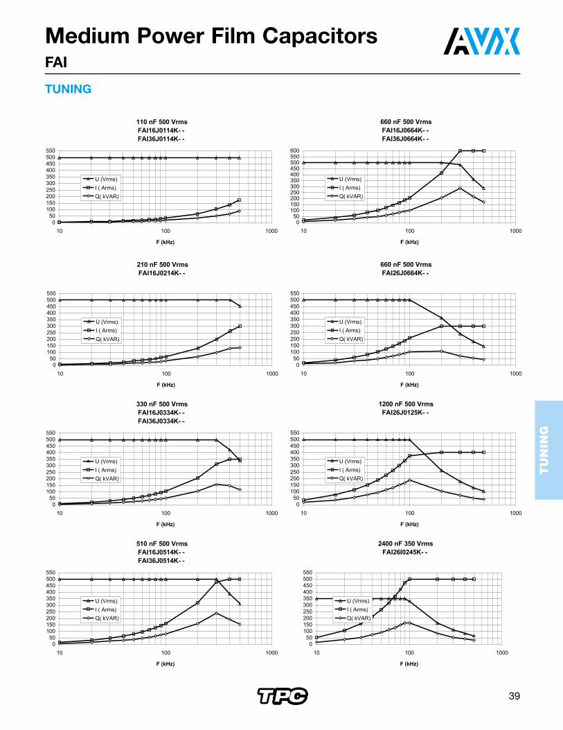
C Irms max Vrms max Q max Rs RthL max H max Part Number(nF) (A) (V) kVARS (mΩ) (°C/W)
110 180 500 100 0.3 0.82 55 (2.165) 35 (1.378) FAI36J0114K--330 350 500 175 0.15 0.55 75 (2.953) 37 (1.457) FAI36J0334K--510 500 500 250 0.1 0.3 95 (3.740) 42 (1.654) FAI36J0514K--660 600 500 300 0.1 0.24 95 (3.740) 42 (1.654) FAI36J0664K--
With F in Hz
FAI2 VERSION
FAI3 VERSION
C Irms max Vrms max Q max Rs RthL max H max Part Number(nF) (A) (V) kVARS (mΩ) (°C/W)
660 300 500 180 5 x 10⁻⁴ x √ F + 0.25 0.6 75 (2.953) 40 (1.575) FAI26J0664K--1200 400 500 200 5 x 10⁻⁴ x √ F + 0.20 0.56 75 (2.953) 40 (1.575) FAI26J0125K--2400 500 350 175 5 x 10⁻⁴ x √ F + 0.17 0.55 75 (2.953) 40 (1.575) FAI26I0245K--
Dimensions: millimeters (inches)
Dimensions: millimeters (inches)
C Irms max Vrms max Q max Rs RthL max H max Part Number(nF) (A) (V) kVARS (mΩ) (°C/W)
110 180 500 100 8 x 10⁻⁴ x √ F + 0.19 0.86 55 (2.165) 35 (1.378) FAI16J0114K--210 300 500 150 5 x 10⁻⁴ x √ F + 0.12 0.67 75 (2.953) 40 (1.575) FAI16J0214K--330 350 500 175 5 x 10⁻⁴ x √ F + 0.15 0.54 75 (2.953) 40 (1.575) FAI16J0334K--510 500 500 250 4 x 10⁻⁴ x √ F + 0.08 0.49 95 (3.740) 45 (1.772) FAI16J0514K--
Medium Power Film CapacitorsFAI
FAI1 VERSION
With F in Hz
Dimensions: millimeters (inches)
TUNING
39
TU
NIN
G
Medium Power Film CapacitorsFAI
TUNING

40
TU
NIN
G
Medium Power Film CapacitorsFAI
FAI6 Dimensions: millimeters (inches)
WidthVrms max C Qmax Irms max Rs Rth
Part Number(V) (µF) (kVAR) (A) (mΩ) (°C/W)90 200 15 160 800 5.10-4 x √ f(Hz) + 0.025 0.104 FAI66F0156K--
(3.543) 300 12 240 800 5.10-4 x √ f(Hz) + 0.03 0.104 FAI66H0126K--400 7 320 800 5.10-4 x √ f(Hz) + 0.035 0.114 FAI66I0705K--500 5 320 640 5.10-4 x √ f(Hz) + 0.04 0.114 FAI66J0505K--600 3.5 320 530 5.10-4 x √ f(Hz) + 0.05 0.124 FAI66K0355K--650 1.5 320 490 5.10-4 x √ f(Hz) + 0.07 0.134 FAI66A0155K--
190 200 30 240 1200 2.5.10-4 x √ f(Hz) + 0.0125 0.079 FAI66F0306K--(7.480) 300 24 360 1200 2.5.10-4 x √ f(Hz) + 0.015 0.079 FAI66H0246K--
400 14 480 1200 2.5.10-4 x √ f(Hz) + 0.0175 0.084 FAI66I0146K--500 10 600 1200 2.5.10-4 x √ f(Hz) + 0.02 0.084 FAI66J0106K--600 7 640 1070 2.5.10-4 x √ f(Hz) + 0.025 0.089 FAI66K0705K--650 3 640 985 2.5.10-4 x √ f(Hz) + 0.035 0.094 FAI66A0305K--
290 200 45 320 1600 2.10-4 x √ f(Hz) + 0.0083 0.072 FAI66F0456K--(11.417) 300 36 480 1600 2.10-4 x √ f(Hz) + 0.01 0.072 FAI66H0366K--
400 21 640 1600 2.10-4 x √ f(Hz) + 0.0117 0.075 FAI66I0216K--500 15 800 1600 2.10-4 x √ f(Hz) + 0.0133 0.075 FAI66J0156K--600 10.5 960 1600 2.10-4 x √ f(Hz) + 0.0167 0.078 FAI66K1055K--650 4.5 960 1480 2.10-4 x √ f(Hz) + 0.0233 0.082 FAI66A0455K--
390 200 60 400 2000 1.5.10-4 x √ f(Hz) + 0.00625 0.067 FAI66F0606K--(15.354) 300 48 600 2000 1.5.10-4 x √ f(Hz) + 0.0075 0.067 FAI66H0486K--
400 28 800 2000 1.5.10-4 x √ f(Hz) + 0.00875 0.070 FAI66I0286K--500 20 1000 2000 1.5.10-4 x √ f(Hz) + 0.01 0.070 FAI66J0206K--600 14 1200 2000 1.5.10-4 x √ f(Hz) + 0.0125 0.072 FAI66K0146K--650 6 1280 1970 1.5.10-4 x √ f(Hz) + 0.0175 0.075 FAI66A0605K--
TUNING

41
TU
NIN
G
41
Medium Power Film CapacitorsFAI
RESIN MOLDING
2 GROOVES
WATER COOLED CIRCUIT(PIPE 8/10)
TERMINALS
57(2.24)±3 (0.118)
35(1.378)50 (1.97)
±0.5 (0.02)20 (0.787)
20 (0
.787
)
(~20 (0.787)
~20
(0.7
87)
~20
(0.7
87)
12 (0.472)
100
(3.9
37)
Max
.
~70 (2.76)
90 (3.54)±2 (0.078)
175
(6.8
9) ±
2 (0
.078
)
ep: 3
(0.1
18)
RESIN MOLDING
2 GROOVES
WATER COOLED CIRCUIT(PIPE 8/10)
TERMINALS
57(2.24)±3 (0.118)
35(1.378)
50 (1.97)±0.5 (0.02)
50 (1.97)±0.5 (0.02)
50 (1.97)±0.5 (0.02)20 (0.787)
20 (0
.787
)
12 (0.472)
100
(3.9
37)
Max
.
~65 (2.56)
~20
(0.7
87)
~20
(0.7
87)
175
(6.8
9) ±
2 (0
.078
)
ep: 3
(0.1
18)
~160 (6.30)
190 (7.48) ±2 (0.078)
FAI6 WIDTH: 90 (3.543)
FAI6 WIDTH: 190 (7.480)
TUNING Dimensions: millimeters (inches)
RESIN MOLDING
2 GROOVES
WATER COOLED CIRCUIT(PIPE 8/10)
TERMINALS
57(2.24)±3 (0.118)
35(1.378)
50(1.97)±0.5 (0.02)
50(1.97)±0.5 (0.02)
50(1.97)±0.5 (0.02)
50(1.97)±0.5 (0.02)
50(1.97)±0.5 (0.02)20 (0.787)
20 (0
.787
)
12 (0.472)
100
(3.9
37)
Max
.
~100 (3.937)
~20
(0.7
87)
~20
(0.7
87)
175
(6.8
9) ±
2 (0
.078
)
ep: 3
(0.1
18)
~225 (8.858)
290 (11.42) ±2 (0.078)
RESIN MOLDING
2 GROOVESWATER COOLED CIRCUIT(PIPE 8/10)
TERMINALS
57(2.24)±3 (0.118)
35(1.378)
100 (3.937)Max.
50(1.97)±0.5 (0.02)
50(1.97)±0.5 (0.02)
50(1.97)±0.5 (0.02)
50(1.97)±0.5 (0.02)
50(1.97)±0.5 (0.02)
50(1.97)±0.5 (0.02)
50(1.97)±0.5 (0.02)20 (0.787)
20 (0
.787
)
12 (0.472)~100 (3.937)
~20
(0.7
87)
~20
(0.7
87)
175
(6.8
9) ±
2 (0
.078
)
ep: 3
(0.1
18)
~325 (12.80)
390 (15.35) ±2 (0.078)
FAI6 WIDTH: 290 (11.417)
FAI6 WIDTH: 390 (15.354)

42
TU
NIN
G
Medium Power Film CapacitorsFAI
TUNING

43
TU
NIN
G
Medium Power Film CapacitorsFAI
7F 400 Vrms Width 90 mmFAI66I0705K- -
0
100
200
300
400
500
600
700
800
10 100
F (kHz)
U (Vrms)
I ( Arms)
Q( kVAR)
14F 400 Vrms Width 190 mmFAI66I0146K- -
0
200
400
600
800
1000
1200
10 100
F (kHz)
U (Vrms)
I ( Arms)
Q( kVAR)
21 F 400 Vrms Width 290 mmFAI66I0216K- -
0
200
400
600
800
1000
1200
1400
1600
10 100
F (kHz)
U (Vrms)
I ( Arms)
Q( kVAR)
28 F 400 Vrms Width 390 mmFAI66I0286K- -
0
500
1000
1500
2000
10 100
F (kHz)
U (Vrms)
I ( Arms)
Q( kVAR)
5 F 500 Vrms Width 90 mmFAI66J0505K- -
0
100
200
300
400
500
600
700
10 100
F (kHz)
U (Vrms)
I ( Arms)
Q( kVAR)
10F 500 Vrms Width 190 mmFAI66J0106K- -
0
200
400
600
800
1000
1200
10 100
F (kHz)
U (Vrms)
I ( Arms)
Q( kVAR)
15 F 500 Vrms Width 290 mmFAI66J0156K- -
0
200
400
600
800
1000
1200
1400
1600
10 100
F (kHz)
U (Vrms)
I ( Arms)
Q( kVAR)
20 F 500 Vrms Width 390 mmFAI66J0206K- -
0
500
1000
1500
2000
10 100
F (kHz)
U (Vrms)
I ( Arms)
Q( kVAR)
TUNING

44
TU
NIN
G
Medium Power Film CapacitorsFAI
3.5 F 600 Vrms Width 90 mmFAI66K0355K- -
0
100
200
300
400
500
600
10 100
F (kHz)
U (Vrms)
I ( Arms)
Q( kVAR)
7F 600 Vrms Width 190 mmFAI66K0705K- -
0
200
400
600
800
1000
1200
10 100
F (kHz)
U (Vrms)
I ( Arms)
Q( kVAR)
10.5F 600 Vrms Width 290 mmFAI66K1055K- -
0
200
400
600
800
1000
1200
1400
1600
10 100
F (kHz)
U (Vrms)
I ( Arms)
Q( kVAR)
14F 600 Vrms Width 390 mmFAI66K0146K- -
0
500
1000
1500
2000
10 100
F (kHz)
U (Vrms)
I ( Arms)
Q( kVAR)
1.5 F 650 Vrms Width 90 mmFAI66A0155K- -
0
100
200
300
400
500
600
700
10 100
F (kHz)
U (Vrms)rms)
I ( Arms)Arms)
Q( kVkVAR)AR)
3F 650 Vrms Width 190 mmFAI66A0305K- -
0100200300400500600700800900
1000
10 100
F (kHz)
U (Vrms)
I ( Arms)
Q( kVAR)
4.5 F 650 Vrms Width 290 mmFAI66A0455K- -
0
200
400
600
800
1000
1200
1400
1600
10 100
F (kHz)
U (Vrms)
I ( Arms)
Q( kVAR)
6F 650 Vrms Width 390 mmFAI66A0605K- -
0
500
1000
1500
2000
10 100
F (kHz)
U (Vrms)
I ( Arms)
Q( kVAR)
TUNING

45
Medium Power Film CapacitorsWorksheet for Custom Requirements
Company ______________________________________________________________________________________________
Name______________________________________________________Phone Number ______________________________
Department _________________________________________________Fax Number ________________________________
Address ____________________________________________________E-mail _____________________________________
ELECTRICAL CHARACTERISTICS
Applications DC Filtering Protection* Tuning
Capacitance (C) ______________ uF ______________ uF ______________ uF
Tolerance (%) ______________ % ______________ % ______________ %
Operating Voltage ______________ Vdc _____Vpk / _____ Vdc* ______________ Vrms
Ripple Voltage ______________ Vr
Working Frequency (f) ______________ Hz ______________ Hz
Operating Current (Irms) ______________ Irms ______________ Irms ______________ Irms
Maximum Current (Imax) ______________ Imax
Maximum Peak Current (Ipeak) ______________ Ipk ______________ Ipk
Maximum Inductance (Ls) ______________ nH ______________ nH ______________ nH
Test voltage between terminals ______________ V ______________ V ______________ V
Maximum surge voltages (MSV) ______________ V ______________ V
MSV duration / frequency _____ s _____/ year _____ s _____/ year
* - Due to the particularities of varying waveforms in such applications more information on the exact nature of wave-
forms is generally required for a full analysis.
THERMAL CHARACTERISTICS
Storage temp. ____min ____ avg ____ max (C) Operating Temp ____ min ____ avg ____ max (C)
Cooling Method (check one) - Natural Convection _____ Forced Air _____ Water ____
Dimensions / shape (please indicate in. / mm.) _____________________________________________
# and type of bushings ____________________ Environment _______________________________
Operating Position: (circle one) (vertical / horizontal / inclined / other __________)
Other information / drawing / block diagram of circuit:
_______________________________________________________________________________________________________
_______________________________________________________________________________________________________
_______________________________________________________________________________________________________
Please send this to your local AVX representative.

S-CPEM10M1000-N
Contact:
USA
AVX Myrtle Beach, SCCorporate Offices
Tel: 843-448-9411FAX: 843-626-5186
AVX Northwest, WATel: 360-669-8746
FAX: 360-699-8751
AVX North Central, INTel: 317-848-7153
FAX: 317-844-9314
AVX Northeast, MATel: 508-485-8114
FAX: 508-485-8471
AVX Mid-Pacific, CATel: 408-436-5400
FAX: 408-437-1500
AVX Southwest, AZTel: 480-539-1496
FAX: 480-539-1501
AVX South Central, TXTel: 972-669-1223
FAX: 972-669-2090
AVX Southeast, NCTel: 919-878-6357
FAX: 919-878-6462
AVX CanadaTel: 905-564-8959
FAX: 905-564-9728
EUROPE
AVX Limited, EnglandEuropean Headquarters
Tel: ++44 (0)1252 770000FAX: ++44 (0)1252 770001
AVX S.A., FranceTel: ++33 (1) 69.18.46.00
FAX: ++33 (1) 69.28.73.87
AVX GmbH, Germany - AVXTel: ++49 (0) 8131 9004-0
FAX: ++49 (0) 8131 9004-44
AVX GmbH, Germany - ElcoTel: ++49 (0) 2741 2990
FAX: ++49 (0) 2741 299133
AVX srl, ItalyTel: ++390 (0)2 614571
FAX: ++390 (0)2 614 2576
AVX Czech Republic, s.r.o.Tel: ++420 (0)467 558340
FAX: ++420 (0)467 558345
A KYOCERA GROUP COMPANY
http://www.avxcorp.com
ASIA-PACIFIC
AVX/Kyocera, SingaporeAsia-Pacific Headquarters
Tel: (65) 258-2833FAX: (65) 350-4880
AVX/Kyocera, Hong KongTel: (852) 2-363-3303
FAX: (852) 2-765-8185
AVX/Kyocera, KoreaTel: (82) 2-785-6504
FAX: (82) 2-784-5411
AVX/Kyocera, TaiwanTel: (886) 2-2696-4636
FAX: (886) 2-2696-4237
AVX/Kyocera, ChinaTel: (86) 21-6249-0314-16FAX: (86) 21-6249-0313
AVX/Kyocera, MalaysiaTel: (60) 4-228-1190
FAX: (60) 4-228-1196
Elco, JapanTel: 045-943-2906/7FAX: 045-943-2910
Kyocera, Japan - AVXTel: (81) 75-604-3426
FAX: (81) 75-604-3425
Kyocera, Japan - KDPTel: (81) 75-604-3424
FAX: (81) 75-604-3425


