258
USER MANUAL 1000Z01 TCA 1800 Leica TPS - System 1000 System Version 2.4 English
USER
MAN
UAL
1000
Z01
TCA 1800
Leica TPS - System 1000System
Version 2.4English
2 TPS-System 1000-2.4.0en © Leica
CO
IN
ID
PM
FS
SC
OC
IO
AR
RC
EG
CA
CT
BC
DF
SD
TS
IX
Congratulations on your purchase of aTPS - System 1000.
This manual contains important safety directions (referto chapter "Safety directions") as well as instructionsfor setting up the instrument and operating it.Read carefully through the User Manual before youswitch on the instrument.

© Leica TPS-System 1000-2.4.0en 3
CO
IN
ID
PM
FS
SC
OC
IO
AR
RC
EG
CA
CT
BC
DF
SD
TS
IX
Leica TPS - System 1000System
Electronic theodolites and total stations
The instrument model and the serial number of yourproduct are indicated on the label in the batterycompartment.Enter the model and serial number in your manual andalways refer to this information when you need tocontact your agency or authorized service workshop.
Type: ___________ Serial number: ___________
Product identification
4 TPS-System 1000-2.4.0en © Leica
CO
IN
ID
PM
FS
SC
OC
IO
AR
RC
EG
CA
CT
BC
DF
SD
TS
IX
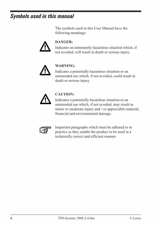
The symbols used in this User Manual have thefollowing meanings:
DANGER:Indicates an imminently hazardous situation which, ifnot avoided, will result in death or serious injury.
WARNING:Indicates a potentially hazardous situation or anunintended use which, if not avoided, could result indeath or serious injury.
CAUTION:Indicates a potentially hazardous situation or anunintended use which, if not avoided, may result inminor or moderate injury and / or appreciable material,financial and environmental damage.
Important paragraphs which must be adhered to inpractice as they enable the product to be used in atechnically correct and efficient manner.
Symbols used in this manual
© Leica TPS-System 1000-2.4.0en 5
CO
IN
ID
PM
FS
SC
OC
IO
AR
RC
EG
CA
CT
BC
DF
SD
TS
IX
Leica TPS-System 1000 Registration Card
Part 1 This card comprises two parts:- Retain part 1 for your records- Return part 2 to Leica Geosystems AG, CH-9435
Heerbrugg, Switzerland - Your name and address, theserial number of the instrument will be registered andyou will receive confirmation of this registration. -Your local Leica representative will also receiveconfirmation
Act immediately
Complete and return part 2 to ensure that you receivesoftware support. If you do not, you will not beregistered and Leica will not be able to provide thesupport that you may need.
Software support
Once your name, your address and the serial number ofthe instrument are registered Leica will, at its discretion,provide you with the following support free of charge:
- Instructions about any corrections and/ormodifications that are necessary for the correctfunctioning of the software as supplied to you.
- Disks containing corrections and/or modificationsnecessary for the correct functioning of the softwareas supplied to you.
6 TPS-System 1000-2.4.0en © Leica
CO
IN
ID
PM
FS
SC
OC
IO
AR
RC
EG
CA
CT
BC
DF
SD
TS
IX
Limit to software support
Once your name, address and instrument are registeredLeica undertakes to provide reasonable support for thesoftware as supplied to you. This software support doesNOT extend to upgrades to new versions of software asmay be introduced by Leica in the future.
Upgrade, enhancement, and exchange programs
Only registered users will receive automatic notificationof possible future product enhancements.
Change of address
Should you change your address after registering forsoftware support, please write to Leica Geosystems AG,CH-9435 Heerbrugg, Switzerland,fax no +41 71 727 46 73, giving details of your newaddress, telephone and telefax numbers.
© Leica TPS-System 1000-2.4.0en 7
CO
IN
ID
PM
FS
SC
OC
IO
AR
RC
EG
CA
CT
BC
DF
SD
TS
IX
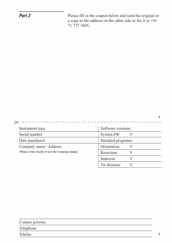
Part 2
Instrument type Software versions:Serial number System SW VDate purchased Standard programs:Company name / Address Orientation V
Resection VStakeout VTie distance V
Contact personsTelephoneTelefax
(Please write clearly or use the Company stamp)
Please fill in the coupon below and send the original ora copy to the address on the other side or fax it to +4171 727 3605.
7

8 TPS-System 1000-2.4.0en © Leica
CO
IN
ID
PM
FS
SC
OC
IO
AR
RC
EG
CA
CT
BC
DF
SD
TS
IX
Software-Support RegistrationLeica Geosystems AGCH-9435 HeerbruggSwitzerland
8
© Leica TPS-System 1000-2.4.0en 9
CO
IN
ID
PM
FS
SC
OC
IO
AR
RC
EG
CA
CT
BC
DF
SD
TS
IX
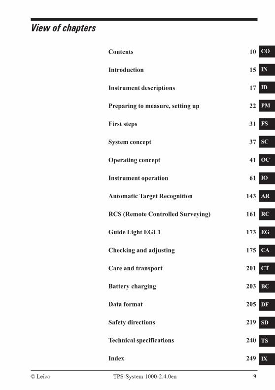
View of chapters
Contents 10
Introduction 15
Instrument descriptions 17
Preparing to measure, setting up 22
First steps 31
System concept 37
Operating concept 41
Instrument operation 61
Automatic Target Recognition 143
RCS (Remote Controlled Surveying) 161
Guide Light EGL1 173
Checking and adjusting 175
Care and transport 201
Battery charging 203
Data format 205
Safety directions 219
Technical specifications 240
Index 249
10 TPS-System 1000-2.4.0en © Leica
CO
IN
ID
PM
FS
SC
OC
IO
AR
RC
EG
CA
CT
BC
DF
SD
TS
IX
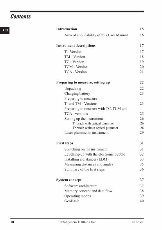
Contents
Introduction 15Area of applicability of this User Manual 16
Instrument descriptions 17T - Version 17TM - Version 18TC - Version 19TCM - Version 20TCA - Version 21
Preparing to measure, setting up 22Unpacking 22Charging battery 23Preparing to measureT- and TM - Versions 23Preparing to measure with TC, TCM andTCA - versions 25Setting up the instrument 26
Tribrach with optical plummet 26Tribrach without optical plummet 28
Laser plummet in instrument 29
First steps 31Switching on the instrument 31Levelling-up with the electronic bubble 32Installing a distancer (EDM) 33Measuring distances and angles 35Summary of the first steps 36
System concept 37Software architecture 37Memory concept and data flow 38Operating modes 39GeoBasic 40
© Leica TPS-System 1000-2.4.0en 11
CO
IN
ID
PM
FS
SC
OC
IO
AR
RC
EG
CA
CT
BC
DF
SD
TS
IX
Operating concept 41Display / keyboard 42Types of dialog 43
Program-selection dialog 43Input/output dialog 44Character field 46Numeric field 49List field 50Two-value field 52
Heading 52Time 52Battery display 53Graphical status icons 53Function keys 56Fixed keys 57Control keys 58Enter keys 58Menu tree (Main menu after ON) 59
Instrument operation 61Main menu 61Fixed-key occupation in the main menu 62Fixed-key occupation 63Measurement & recording 64
Measuring distances and angles together 67Measuring distances and angles separately 68Target-point data 70Remarks 71Incrementing point numbers 72Set and define prisms 73Reduced input of ppm values 75Comprehensive distance corrections (ppm) 76Manual distance entry 79Target eccentricity 80Individual point number 81
Set station data 82Select user template and measurement file 82Station entry/setting 821-point orientation 88
12 TPS-System 1000-2.4.0en © Leica
CO
IN
ID
PM
FS
SC
OC
IO
AR
RC
EG
CA
CT
BC
DF
SD
TS
IX
Data management 90Entering coordinates 91Deleting data 91View data 92Edit data 92
Leica prisms and retro tapes 93Prism for attachable EDM 93Prism for incorporated EDM 94The GRZ4 360° reflector 95Leica retro tapes 96Summary 97Long distances 97
Extra 98On-line mode 99Format a memory card 100Remote-control mode 101
Configuration 102System date and time 104Define functionality 105Interface parameters (GSI) 107Interface parameters (GeoCOM) 108Instrument identification 109Auto-start configuration 110System protection 111User configurations 113
Functions of the fixed keys 124Code information 124Illumination 126Electronic bubble 128aF... - Additional functions 129ON/OFF 141EDM selection 142
Automatic Target Recognition 143Functionality 144Operation 146Automatic Target Recognition ATR1 resolutionmodes 152Information on the use of Automatic TargetRecognition ATR1 156
Reduction of the range 157Disturbance 158

© Leica TPS-System 1000-2.4.0en 13
CO
IN
ID
PM
FS
SC
OC
IO
AR
RC
EG
CA
CT
BC
DF
SD
TS
IX
RCS (Remote Controlled Surveying) 161Introduction 161Setting up 163Allocation of keys 166Working procedure 167
Compass 168Hz / V 170Joystick 171Lock interruption 172Last point stored 172
Guide Light EGL1 173ON / OFF 173
Checking and adjusting 175Electronically 175
Compensator (electronic bubble) 177V-index error 180Line of sight 184Tilting axis 188Combined error determination 191ATR1 collimation 191
Mechanically 195Tripod 195Bull's eye bubble on instrument 196Bull's eye bubble on the tribrach 196Optical plummet 197
Laser plummet 199
Care and transport 201
Battery charging 203Battery chargers GKL22 and GKL23 203Battery chargers GKL12 and GKL14 204
Data format 205Introduction 205GSI storage format with 8 or 16 characters 205Block concept 206Code block 207
14 TPS-System 1000-2.4.0en © Leica
CO
IN
ID
PM
FS
SC
OC
IO
AR
RC
EG
CA
CT
BC
DF
SD
TS
IX
Structure of a block 207Measurement block 207Terminator of a data block 208Structure of a word 208
Word index (positions 1 - 2) 209Information relating to data (positions 3 - 6) 211Data (positions 7 - 15/23) 213Separating character (position 16/24) 214Block number 214Units of measurement 215
Example of data format 216
Safety directions 219Intended use of instrument 219Limits of use 221Responsibilities 221Hazards of use 222Laser classification 228
Integrated distancer (EDM) 228Automatic target recognition (ATR1) 229Guide light EGL1 231Laser plummet 233
Electromagnetic acceptability 237FCC statement (applicable in U.S.) 238
Product labeling 239
Technical specifications 240Technical specifications of the Automatic TargetRecognition ATR1 244Technical specifications of the EGL1 GuideLight 245Application programs 246Atmospheric corrections 247
Index 249
© Leica TPS-System 1000-2.4.0en 15
CO
IN
ID
PM
FS
SC
OC
IO
AR
RC
EG
CA
CT
BC
DF
SD
TS
IX
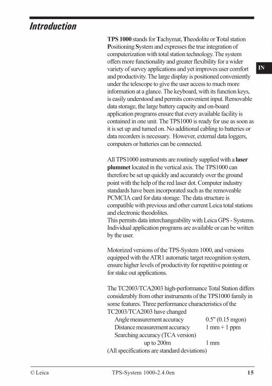
TPS 1000 stands for Tachymat, Theodolite or Total stationPositioning System and expresses the true integration ofcomputerization with total station technology. The systemoffers more functionality and greater flexibility for a widervariety of survey applications and yet improves user comfortand productivity. The large display is positioned convenientlyunder the telescope to give the user access to much moreinformation at a glance. The keyboard, with its function keys,is easily understood and permits convenient input. Removabledata storage, the large battery capacity and on-boardapplication programs ensure that every available facility iscontained in one unit. The TPS1000 is ready for use as soon asit is set up and turned on. No additional cabling to batteries ordata recorders is necessary. However, external data loggers,computers or batteries can be connected.
All TPS1000 instruments are routinely supplied with a laserplummet located in the vertical axis. The TPS1000 cantherefore be set up quickly and accurately over the groundpoint with the help of the red laser dot. Computer industrystandards have been incorporated such as the removeablePCMCIA card for data storage. The data structure iscompatible with previous and other current Leica total stationsand electronic theodolites.This permits data interchangeability with Leica GPS - Systems.Individual application programs are available or can be writtenby the user.
Motorized versions of the TPS-System 1000, and versionsequipped with the ATR1 automatic target recognition system,ensure higher levels of productivity for repetitive pointing orfor stake out applications.
The TC2003/TCA2003 high-performance Total Station differsconsiderably from other instruments of the TPS1000 family insome features. Three performance characteristics of theTC2003/TCA2003 have changed
Angle measurement accuracy 0.5" (0.15 mgon)Distance measurement accuracy 1 mm + 1 ppmSearching accuracy (TCA version)
up to 200m 1 mm(All specifications are standard deviations)
Introduction

16 TPS-System 1000-2.4.0en © Leica
CO
IN
ID
PM
FS
SC
OC
IO
AR
RC
EG
CA
CT
BC
DF
SD
TS
IX
All instruments of the 2003 version are supplied with aquality certificate.
As standard the application software"Monitoring" isimplemented in the TCA2003.
The TC2003/TCA2003 instruments are equipped with aspecial carrying handle. This handle is an integratedpart of the instrument and should always be fitted to theinstrument during measurements.
Make sure that the carrying handle is carefully fitted tothe instrument and that the mounting screws are tighten.
Area of applicability ofthis User Manual
This manual applies to all TPS1000 instruments and tothe TC2003/TCA2003 instruments.
Differences between the various models are clearly setout and assigned.General text applies to all types.
General illustrations represent the TCA 1800instrument with EGL1 guide light option and apply toall models.
The present User Manual is valid for the softwareversion 2.2.
© Leica TPS-System 1000-2.4.0en 17
CO
IN
ID
PM
FS
SC
OC
IO
AR
RC
EG
CA
CT
BC
DF
SD
TS
IX
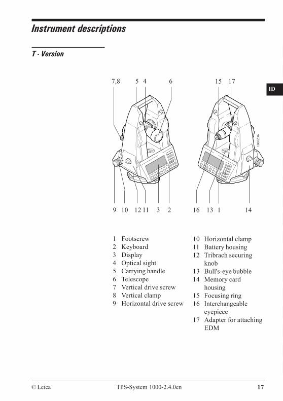
T - Version
10 Horizontal clamp11 Battery housing12 Tribrach securing
knob13 Bull's-eye bubble14 Memory card
housing15 Focusing ring16 Interchangeable
eyepiece17 Adapter for attaching
EDM
1 Footscrew2 Keyboard3 Display4 Optical sight5 Carrying handle6 Telescope7 Vertical drive screw8 Vertical clamp9 Horizontal drive screw
45 67,8
1311 3 212 1419 10
1000
Z36
16
15 17
Instrument descriptions
18 TPS-System 1000-2.4.0en © Leica
CO
IN
ID
PM
FS
SC
OC
IO
AR
RC
EG
CA
CT
BC
DF
SD
TS
IX
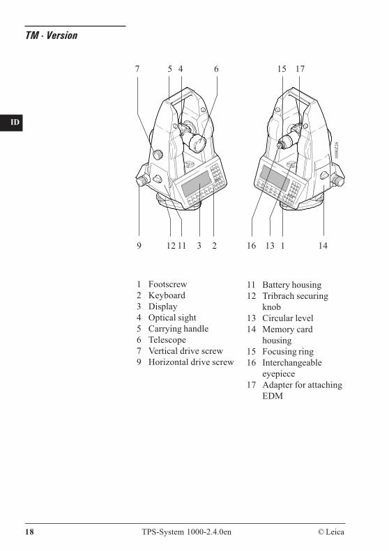
TM - Version
11 Battery housing12 Tribrach securing
knob13 Circular level14 Memory card
housing15 Focusing ring16 Interchangeable
eyepiece17 Adapter for attaching
EDM
1 Footscrew2 Keyboard3 Display4 Optical sight5 Carrying handle6 Telescope7 Vertical drive screw9 Horizontal drive screw
45 6
1311 3 212 1419
1000
Z26
7
16
15 17
© Leica TPS-System 1000-2.4.0en 19
CO
IN
ID
PM
FS
SC
OC
IO
AR
RC
EG
CA
CT
BC
DF
SD
TS
IX
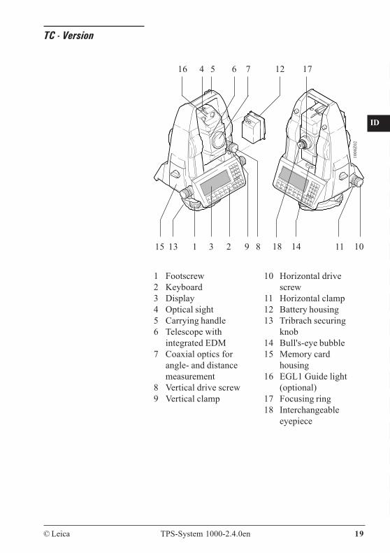
TC - Version
1 Footscrew2 Keyboard3 Display4 Optical sight5 Carrying handle6 Telescope with
integrated EDM7 Coaxial optics for
angle- and distancemeasurement
8 Vertical drive screw9 Vertical clamp
10 Horizontal drivescrew
11 Horizontal clamp12 Battery housing13 Tribrach securing
knob14 Bull's-eye bubble15 Memory card
housing16 EGL1 Guide light
(optional)17 Focusing ring18 Interchangeable
eyepiece
1 3
4 5 6 7
89
1000
Z02
111315
12
2
16
101418
17
20 TPS-System 1000-2.4.0en © Leica
CO
IN
ID
PM
FS
SC
OC
IO
AR
RC
EG
CA
CT
BC
DF
SD
TS
IX
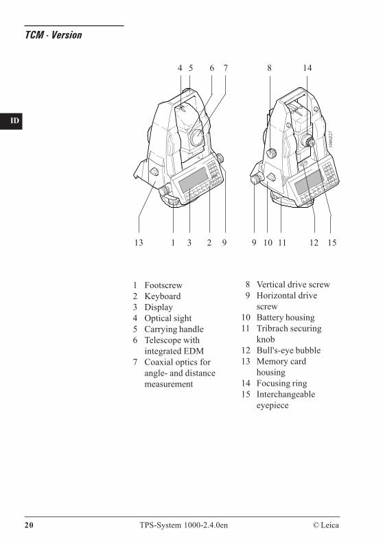
TCM - Version
1 Footscrew2 Keyboard3 Display4 Optical sight5 Carrying handle6 Telescope with
integrated EDM7 Coaxial optics for
angle- and distancemeasurement
8 Vertical drive screw9 Horizontal drive
screw10 Battery housing11 Tribrach securing
knob12 Bull's-eye bubble13 Memory card
housing14 Focusing ring15 Interchangeable
eyepiece
1 3 2
4 5 6 7
913
1000
Z27
8
10 11 129 15
14

© Leica TPS-System 1000-2.4.0en 21
CO
IN
ID
PM
FS
SC
OC
IO
AR
RC
EG
CA
CT
BC
DF
SD
TS
IX
TCA - Version
8 Vertical drive screw9 Horizontal drive
screw10 Battery housing11 Tribrach securing
knob12 Bull's-eye bubble13 Memory card housing14 Focusing ring15 Interchangeable
eyepiece
1 Footscrew2 Keyboard3 Display4 Optical sight5 Carrying handle6 Telescope with
integrated EDM7 Coaxial optics for
angle- and distancemeasurement
with EGL1 Guide light (Option):16 EGL1 Guide light17 Flashing left diode (yellow)18 Flashing right diode (red)
1 3 2
4 5
121113
17 18 6/16 7 8
9 10
1000
Z28
15
14
22 TPS-System 1000-2.4.0en © Leica
CO
IN
ID
PM
FS
SC
OC
IO
AR
RC
EG
CA
CT
BC
DF
SD
TS
IX
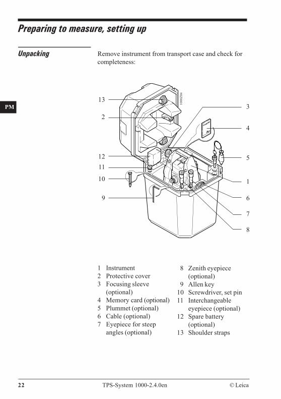
Preparing to measure, setting up
Remove instrument from transport case and check forcompleteness:
8 Zenith eyepiece(optional)
9 Allen key10 Screwdriver, set pin11 Interchangeable
eyepiece (optional)12 Spare battery
(optional)13 Shoulder straps
1 Instrument2 Protective cover3 Focusing sleeve
(optional)4 Memory card (optional)5 Plummet (optional)6 Cable (optional)7 Eyepiece for steep
angles (optional)
5
1
23
4
6
7
1000
Z04
8
9
10
1112
13
Unpacking

© Leica TPS-System 1000-2.4.0en 23
CO
IN
ID
PM
FS
SC
OC
IO
AR
RC
EG
CA
CT
BC
DF
SD
TS
IX
Charging battery Charge batteries using GKL12, GKL14, GKL22 orGKL23. For more information about charging batteriesrefer to chapter "Battery charging".
GEB87
GEB87
1000
QS0
9
GKL23 ( )GKL23-1 ( )
/
230V ±10% 115V +10/-20%
Charging time: 1.5 hoursExternal batteries:GEB70: 1.5 hoursGEB71: 5.0 hours
WARNING:The battery chargers are intended for indoor use only.Use a battery charger in a dry room only, neveroutdoors.
Preparing to measureT- and TM - Versions
Before using the theodolite version for the first time,certain precautions need to be taken:
The black plastic protective cover on the telescopeconnector should be removed with a knife blade orscrewdriver before fitting the EDM (=ElectronicDistance Measuring instrument).

24 TPS-System 1000-2.4.0en © Leica
CO
IN
ID
PM
FS
SC
OC
IO
AR
RC
EG
CA
CT
BC
DF
SD
TS
IX GPH1A single-prism holder
1000
Z024
1000
Z029
Remove the protective plastic cover
When the theodolite is used in conjunction with theEMD models DI1001, DI1600, or DI2002, werecommend using the GPH1A single-prism holder formeasuring over short distances.
Measuring with connected EDM is to be performedwhen the EDM is above the telescope, otherwisedistances may be reduced wrongly.
Make sure that the ppm- and mm-values stored in theEDM are reset to "0.00".
Line up the axis of the EDM to that of the theodolite asdescribed in the user manual for the EDM, but firstenter the model of EDM in the TPS1000. For moreinformation, please refer to the chapter "First steps".
© Leica TPS-System 1000-2.4.0en 25
CO
IN
ID
PM
FS
SC
OC
IO
AR
RC
EG
CA
CT
BC
DF
SD
TS
IX
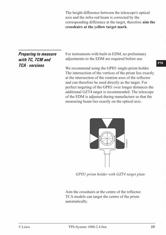
The height difference between the telescope's opticalaxis and the infra-red beam is corrected by thecorresponding difference at the target, therefore aim thecrosshairs at the yellow target mark.
Preparing to measurewith TC, TCM andTCA - versions
For instruments with built-in EDM, no preliminaryadjustments to the EDM are required before use.
We recommend using the GPH1 single-prism holder.The intersection of the vertices of the prism lies exactlyat the intersection of the rotation axes of the reflectorand can therefore be used directly as the target. Forperfect targeting of the GPH1 over longer distances theadditional GZT4 target is recommended. The telescopeof the EDM is adjusted during manufacture so that themeasuring beam lies exactly on the optical axis.
TC60
0Z11
GPH1 prism holder with GZT4 target plate
Aim the crosshairs at the centre of the reflector.TCA models can target the centre of the prismautomatically.
26 TPS-System 1000-2.4.0en © Leica
CO
IN
ID
PM
FS
SC
OC
IO
AR
RC
EG
CA
CT
BC
DF
SD
TS
IX
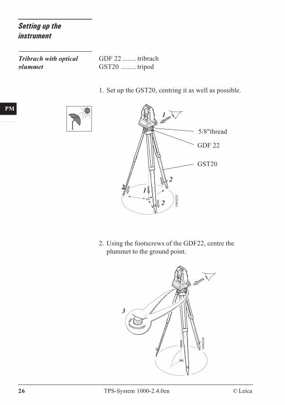
Setting up theinstrument
Tribrach with opticalplummet
GDF 22 ........ tribrachGST20 ......... tripod
1. Set up the GST20, centring it as well as possible.
3
1000
Z06
2. Using the footscrews of the GDF22, centre theplummet to the ground point.
5/8"thread
2
GST20
GDF 22
1
1
2
210
00Z0
5
© Leica TPS-System 1000-2.4.0en 27
CO
IN
ID
PM
FS
SC
OC
IO
AR
RC
EG
CA
CT
BC
DF
SD
TS
IX
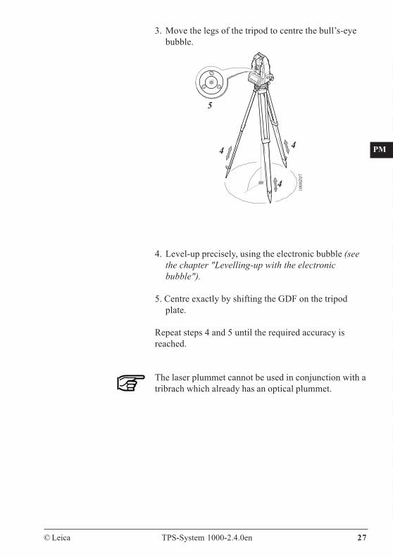
3. Move the legs of the tripod to centre the bull’s-eyebubble.
4
4
5
4
1000
Z07
4. Level-up precisely, using the electronic bubble (seethe chapter "Levelling-up with the electronicbubble").
5. Centre exactly by shifting the GDF on the tripodplate.
Repeat steps 4 and 5 until the required accuracy isreached.
The laser plummet cannot be used in conjunction with atribrach which already has an optical plummet.
28 TPS-System 1000-2.4.0en © Leica
CO
IN
ID
PM
FS
SC
OC
IO
AR
RC
EG
CA
CT
BC
DF
SD
TS
IX
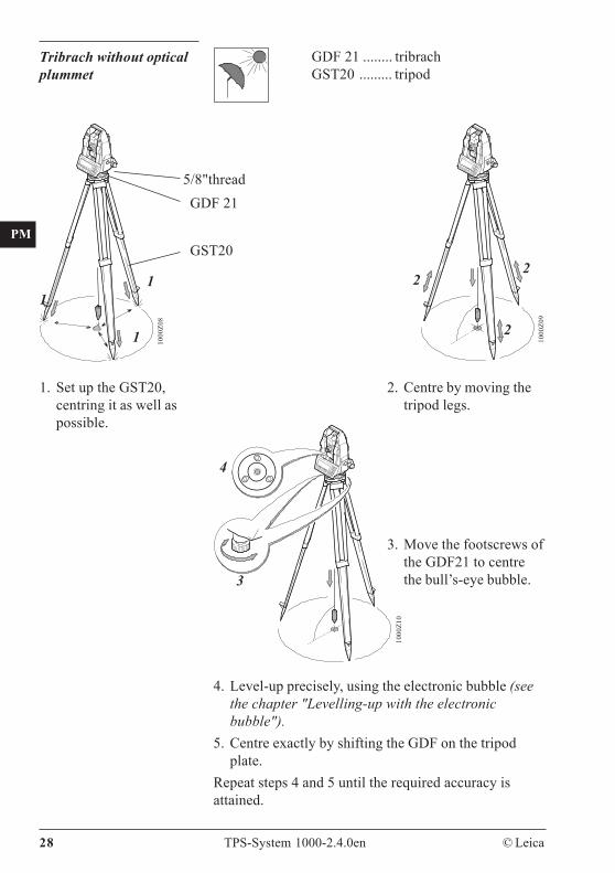
Tribrach without opticalplummet
GDF 21 ........ tribrachGST20 ......... tripod
5/8"thread
1
1
1
GDF 21
GST20
1000
Z08
22
2
1000
Z09
1. Set up the GST20,centring it as well aspossible.
2. Centre by moving thetripod legs.
4. Level-up precisely, using the electronic bubble (seethe chapter "Levelling-up with the electronicbubble").
5. Centre exactly by shifting the GDF on the tripodplate.
Repeat steps 4 and 5 until the required accuracy isattained.
3
4
1000
Z10
3. Move the footscrews ofthe GDF21 to centrethe bull’s-eye bubble.
© Leica TPS-System 1000-2.4.0en 29
CO
IN
ID
PM
FS
SC
OC
IO
AR
RC
EG
CA
CT
BC
DF
SD
TS
IX
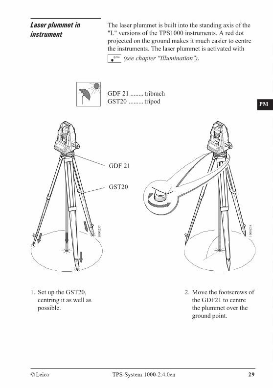
Laser plummet ininstrument
The laser plummet is built into the standing axis of the"L" versions of the TPS1000 instruments. A red dotprojected on the ground makes it much easier to centrethe instruments. The laser plummet is activated with
(see chapter "Illumination").
1000
Z37
2. Move the footscrews ofthe GDF21 to centrethe plummet over theground point.
1. Set up the GST20,centring it as well aspossible.
GDF 21 ........ tribrachGST20 ......... tripod
GDF 21
GST20
1000
Z38
30 TPS-System 1000-2.4.0en © Leica
CO
IN
ID
PM
FS
SC
OC
IO
AR
RC
EG
CA
CT
BC
DF
SD
TS
IX
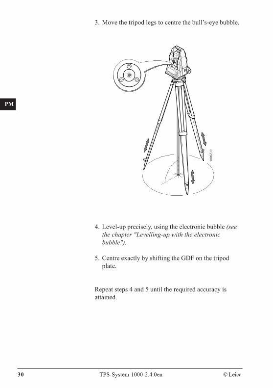
3. Move the tripod legs to centre the bull’s-eye bubble.
1000
Z39
4. Level-up precisely, using the electronic bubble (seethe chapter "Levelling-up with the electronicbubble").
5. Centre exactly by shifting the GDF on the tripodplate.
Repeat steps 4 and 5 until the required accuracy isattained.
© Leica TPS-System 1000-2.4.0en 31
CO
IN
ID
PM
FS
SC
OC
IO
AR
RC
EG
CA
CT
BC
DF
SD
TS
IX
First steps
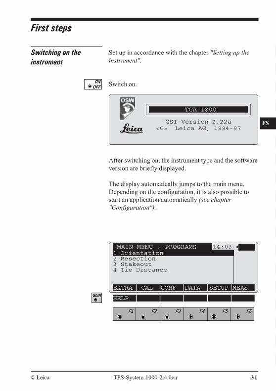
Switching on theinstrument
Set up in accordance with the chapter "Setting up theinstrument".
Switch on.
After switching on, the instrument type and the softwareversion are briefly displayed.
The display automatically jumps to the main menu.Depending on the configuration, it is also possible tostart an application automatically (see chapter"Configuration").
MAIN MENU : PROGRAMS 14:031 Orientation2 Resection3 Stakeout4 Tie Distance
EXTRA CAL CONF DATA SETUP MEAS
F1 F2 F3 F4 F5 F6
HELP
TCA 1800
GSI-Version 2.22a<C> Leica AG, 1994-97
32 TPS-System 1000-2.4.0en © Leica
CO
IN
ID
PM
FS
SC
OC
IO
AR
RC
EG
CA
CT
BC
DF
SD
TS
IX
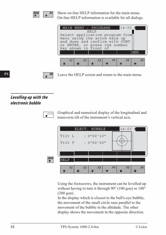
Show on-line HELP information for the main menu.On-line HELP information is available for all dialogs.
MAIN MENU : PROGRAMS 14:03
END
F1 F2 F3 F4 F5 F6
Levelling-up with theelectronic bubble
Graphical and numerical display of the longitudinal andtransverse tilt of the instrument’s vertical axis.
Leave the HELP screen and return to the main menu.
HELPSelect application program frommenu using the arrow keys upand down and confirm with CONTor ENTER, or press the numberkey shown in front of
ELECT. BUBBLE 14:03
Tilt L : 0°00'10"
Tilt T : 0°00'00"
F1 F2 F3 F4 F5 F6
HELP
Using the footscrews, the instrument can be levelled-upwithout having to turn it through 90° (100 gon) or 180°(200 gon).In the display which is closest to the bull's-eye bubble,the movement of the small circle runs parallel to themovement of the bubble in the alhidade. The otherdisplay shows the movement in the opposite direction.
© Leica TPS-System 1000-2.4.0en 33
CO
IN
ID
PM
FS
SC
OC
IO
AR
RC
EG
CA
CT
BC
DF
SD
TS
IX
Installing a distancer(EDM)
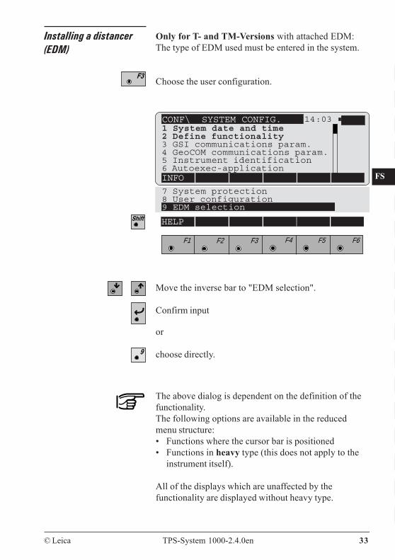
Only for T- and TM-Versions with attached EDM:The type of EDM used must be entered in the system.
Choose the user configuration.
The above dialog is dependent on the definition of thefunctionality.The following options are available in the reducedmenu structure:• Functions where the cursor bar is positioned• Functions in heavy type (this does not apply to the
instrument itself).
All of the displays which are unaffected by thefunctionality are displayed without heavy type.
Move the inverse bar to "EDM selection".
Confirm input
or
choose directly.
CONF\ SYSTEM CONFIG. 14:031 System date and time2 Define functionality3 GSI communications param.4 GeoCOM communications param.5 Instrument identification6 Autoexec-applicationINFO
F1 F2 F3 F4 F5 F6
HELP
7 System protection8 User configuration9 EDM selection
34 TPS-System 1000-2.4.0en © Leica
CO
IN
ID
PM
FS
SC
OC
IO
AR
RC
EG
CA
CT
BC
DF
SD
TS
IX
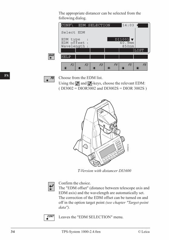
The appropriate distancer can be selected from thefollowing dialog.
CONF\ EDM SELECTION 14:03
Select EDM
EDM type : DI1001EDM offset : 40.9mmWavelength : 850nm
LIST
F1 F2 F3 F4 F5 F6
HELP
Choose from the EDM list.Using the and -keys, choose the relevant EDM:( DI3002 = DIOR3002 and DI3002S = DIOR 3002S )
T-Version with distancer DI1600
1000
Z34
Confirm the choice.The "EDM offset" (distance between telescope axis andEDM axis) and the wavelength are automatically set.The correction of the EDM offset can be turned on andoff in the option target point (see chapter "Target-pointdata").
Leaves the "EDM SELECTION" menu.
© Leica TPS-System 1000-2.4.0en 35
CO
IN
ID
PM
FS
SC
OC
IO
AR
RC
EG
CA
CT
BC
DF
SD
TS
IX
Measuring distancesand angles
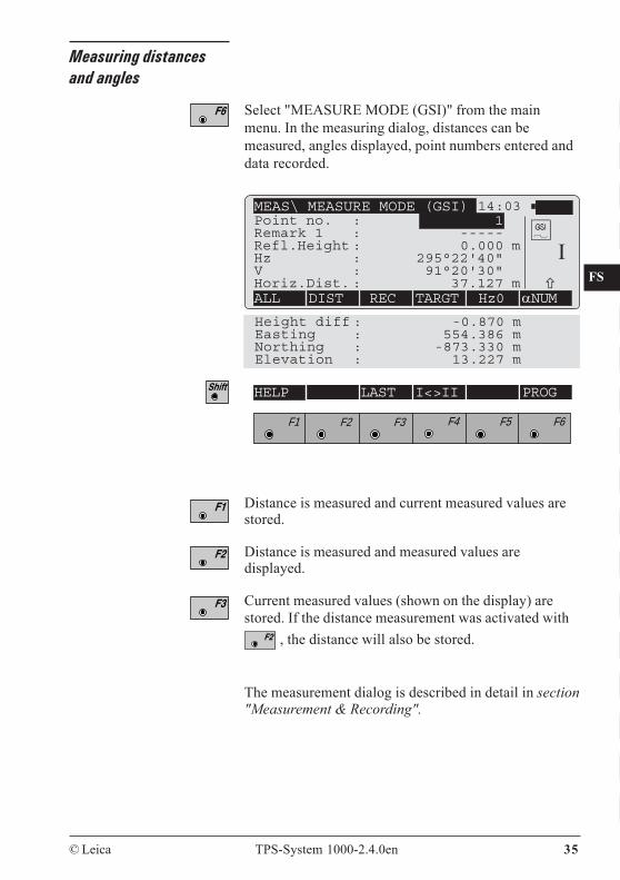
Select "MEASURE MODE (GSI)" from the mainmenu. In the measuring dialog, distances can bemeasured, angles displayed, point numbers entered anddata recorded.
MEAS\ MEASURE MODE (GSI) 14:03Point no. : 1Remark 1 : -----Refl.Height : 0.000 mHz : 295°22'40"V : 91°20'30"Horiz.Dist. : 37.127 mALL DIST REC TARGT Hz0 αNUM
Height diff : -0.870 mEasting : 554.386 mNorthing : -873.330 mElevation : 13.227 m
F1 F2 F3 F4 F5 F6
HELP LAST I<>II PROG
I
Distance is measured and current measured values arestored.
Distance is measured and measured values aredisplayed.
Current measured values (shown on the display) arestored. If the distance measurement was activated with
, the distance will also be stored.
The measurement dialog is described in detail in section"Measurement & Recording".
36 TPS-System 1000-2.4.0en © Leica
CO
IN
ID
PM
FS
SC
OC
IO
AR
RC
EG
CA
CT
BC
DF
SD
TS
IX
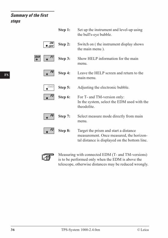
Summary of the firststeps
Step 1: Set up the instrument and level-up usingthe bull's-eye bubble.
Step 2: Switch on ( the instrument display showsthe main menu ).
Step 3: Show HELP information for the mainmenu.
Step 4: Leave the HELP screen and return to themain menu.
Step 5: Adjusting the electronic bubble.
Step 6: For T- and TM-version only:In the system, select the EDM used with thetheodolite.
Step 7: Select measure mode directly from mainmenu.
Step 8: Target the prism and start a distancemeasurement. Once measured, the horizon-tal distance is displayed on the bottom line.
Measuring with connected EDM (T- and TM-versions)is to be performed only when the EDM is above thetelescope, otherwise distances may be reduced wrongly.
© Leica TPS-System 1000-2.4.0en 37
CO
IN
ID
PM
FS
SC
OC
IO
AR
RC
EG
CA
CT
BC
DF
SD
TS
IX
System concept
The TPS1000 series includes many differentinstruments: electronic theodolites and total stations ofvarious accuracy classes, with or without motorization,and total stations with automatic targeting.
All of these models use the same software architectureand the same concept for data storage and data flow.
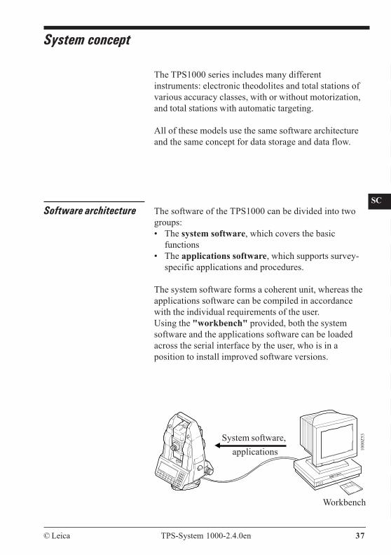
Software architecture The software of the TPS1000 can be divided into twogroups:• The system software, which covers the basic
functions• The applications software, which supports survey-
specific applications and procedures.
The system software forms a coherent unit, whereas theapplications software can be compiled in accordancewith the individual requirements of the user.Using the "workbench" provided, both the systemsoftware and the applications software can be loadedacross the serial interface by the user, who is in aposition to install improved software versions.
1000
Z53
Workbench
System software,applications
38 TPS-System 1000-2.4.0en © Leica
CO
IN
ID
PM
FS
SC
OC
IO
AR
RC
EG
CA
CT
BC
DF
SD
TS
IX
The software permits up to three languages to remainstored simultaneously and one of them to be selected.The range of language versions available is constantlybeing expanded. If you need a particular languageversion, please ask your agency about its availability.
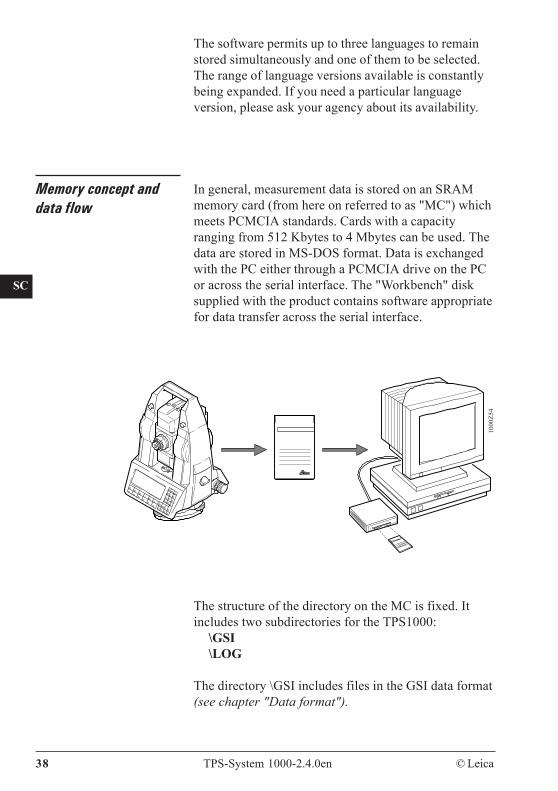
Memory concept anddata flow
In general, measurement data is stored on an SRAMmemory card (from here on referred to as "MC") whichmeets PCMCIA standards. Cards with a capacityranging from 512 Kbytes to 4 Mbytes can be used. Thedata are stored in MS-DOS format. Data is exchangedwith the PC either through a PCMCIA drive on the PCor across the serial interface. The "Workbench" disksupplied with the product contains software appropriatefor data transfer across the serial interface.
The structure of the directory on the MC is fixed. Itincludes two subdirectories for the TPS1000:
\GSI\LOG
The directory \GSI includes files in the GSI data format(see chapter "Data format").
1000
Z54
© Leica TPS-System 1000-2.4.0en 39
CO
IN
ID
PM
FS
SC
OC
IO
AR
RC
EG
CA
CT
BC
DF
SD
TS
IX
A distinction is made between:• Input data, generally fixed-point coordinates• Output data, generally measurements, coordinates, or
derived values relating to "new points".
It is advisable to store the input and output data in twoseparate files, although it is possible to store themtogether in a single file.A maximum of 24 files can be managed. Twelve ofthem already have permanent names (FILE01.GSI toFILE12.GSI) and are used primarily to storemeasurement data (measurement files). The remainingtwelve files can be given any name, but this mustalways terminate with GSI (e.g. PROJ2563.GSI). It isuseful to store the fixed-point coordinates in these files(data files).
In the directory \LOG, additional data from most of theloadable applications can be stored in a protocol file.
Instead of using the MC, the data can be output in GSIformat at the serial data interface.
When data storage is performed across the serialinterface, no data from the applications is output intothe protocol file. Fixed-point coordinates can be readonly from the MC.
Normal operation involves an observer who keys-ininformation and who moves the telescope and points theinstrument manually. The results of the measurementare displayed and stored.
The instrument can also be operated partially bysending user-defined commands across the serialinterface (reduced RS232 interface). If the instrumenthas automatic target recognition, it can be operated fullyin this manner.
Operating modes
40 TPS-System 1000-2.4.0en © Leica
CO
IN
ID
PM
FS
SC
OC
IO
AR
RC
EG
CA
CT
BC
DF
SD
TS
IX
GeoBasic The GeoBasic development environment permits theprofessional development of additional applications forthe TPS1000. For more information, please refer to"GeoBasic Compiler and Keyboard Simulator", a copyof which is available (in English only) from your localLeica agency.
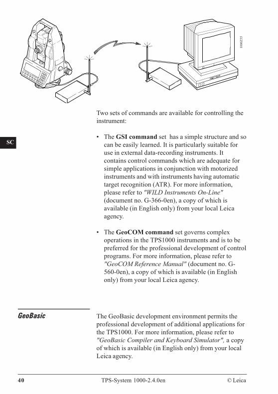
Two sets of commands are available for controlling theinstrument:
• The GSI command set has a simple structure and socan be easily learned. It is particularly suitable foruse in external data-recording instruments. Itcontains control commands which are adequate forsimple applications in conjunction with motorizedinstruments and with instruments having automatictarget recognition (ATR). For more information,please refer to "WILD Instruments On-Line"(document no. G-366-0en), a copy of which isavailable (in English only) from your local Leicaagency.
• The GeoCOM command set governs complexoperations in the TPS1000 instruments and is to bepreferred for the professional development of controlprograms. For more information, please refer to"GeoCOM Reference Manual" (document no. G-560-0en), a copy of which is available (in Englishonly) from your local Leica agency.
1000
Z55

© Leica TPS-System 1000-2.4.0en 41
BK
CO
IN
ID
PM
FS
SC
OC
IO
AR
RC
EG
CA
CT
BC
DF
SD
TS
IX
Operating concept
The TPS1000 system is organized into variousfunctions, which are started via the function keys in themain menu or via the hard keys.
The use of loadable applications can meet specificuser requirements, which are then called up from the listof applications in the main menu.
Each application or function is divided into dialogswhich include interrelated information.

42 TPS-System 1000-2.4.0en © Leica
BK
CO
IN
ID
PM
FS
SC
OC
IO
AR
RC
EG
CA
CT
BC
DF
SD
TS
IX
Display / keyboard The display and the keyboard are divided into specificareas, making the layout clear and the operationalprocedure easy to learn.
Dialog area
Heading
Function key assignment
F1 F2 F3 F4 F5 F6 Shift CE
CODE aF... CONT ON ESCOFF
7 8 9
4 5 6
1 2 3
0 • +/-
1 Orientation2 Resection3 Stakeout4 Tie Distance5 Free Station6 Sets of AnglesEXTRA CAL CONF DATA SETUP MEAS
MAIN MENU : PROGRAMS 14:03
Input keysBattery display Status iconsTime
Control keysRunninginfo-bar
Cursor bar Electronicbubble*
Otherfunctions *
The four colour groupings for the keys are:White: Fixed keysOrange: Function keysGreen: Control keysYellow: Numeric and entry keys
The graphical display is arranged with 8 lines of 35characters. Graphics can be displayed with a resolutionof 64 x 210 pixels across the full display area.
* => always accessible !
Illumination *
© Leica TPS-System 1000-2.4.0en 43
BK
CO
IN
ID
PM
FS
SC
OC
IO
AR
RC
EG
CA
CT
BC
DF
SD
TS
IX
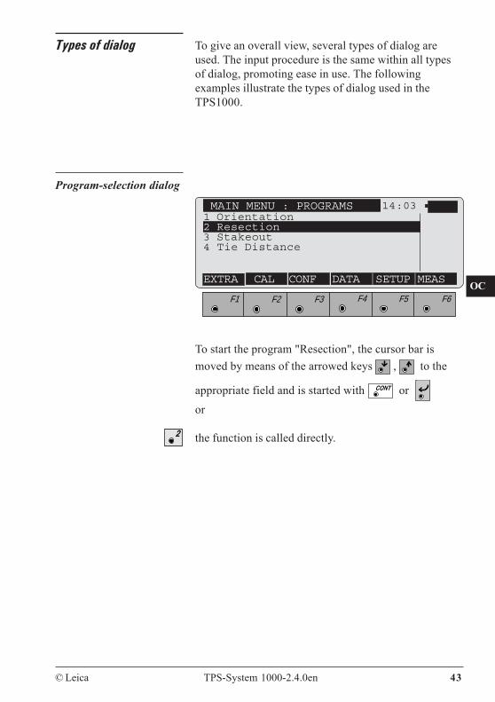
Types of dialog To give an overall view, several types of dialog areused. The input procedure is the same within all typesof dialog, promoting ease in use. The followingexamples illustrate the types of dialog used in theTPS1000.
F1 F2 F3 F4 F5 F6
Program-selection dialog
To start the program "Resection", the cursor bar ismoved by means of the arrowed keys , to the
appropriate field and is started with or or
the function is called directly.
MAIN MENU : PROGRAMS 14:03
EXTRA CAL CONF DATA SETUP MEAS
1 Orientation2 Resection3 Stakeout4 Tie Distance
44 TPS-System 1000-2.4.0en © Leica
BK
CO
IN
ID
PM
FS
SC
OC
IO
AR
RC
EG
CA
CT
BC
DF
SD
TS
IX
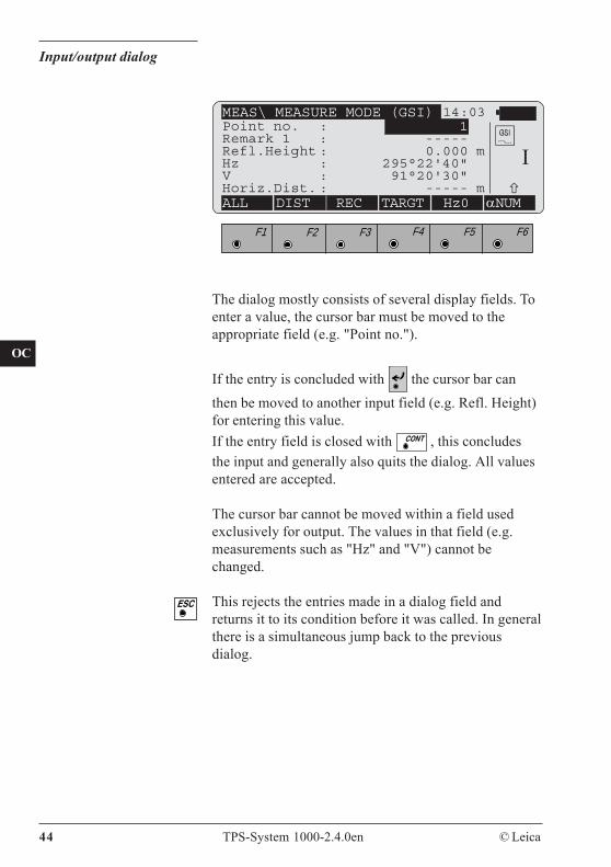
Input/output dialog
F1 F2 F3 F4 F5 F6
The dialog mostly consists of several display fields. Toenter a value, the cursor bar must be moved to theappropriate field (e.g. "Point no.").
If the entry is concluded with the cursor bar canthen be moved to another input field (e.g. Refl. Height)for entering this value.If the entry field is closed with , this concludesthe input and generally also quits the dialog. All valuesentered are accepted.
The cursor bar cannot be moved within a field usedexclusively for output. The values in that field (e.g.measurements such as "Hz" and "V") cannot bechanged.
This rejects the entries made in a dialog field andreturns it to its condition before it was called. In generalthere is a simultaneous jump back to the previousdialog.
MEAS\ MEASURE MODE (GSI) 14:03Point no. : 1Remark 1 : -----Refl.Height : 0.000 mHz : 295°22'40"V : 91°20'30"Horiz.Dist. : ----- mALL DIST REC TARGT Hz0 αNUM
I
© Leica TPS-System 1000-2.4.0en 45
BK
CO
IN
ID
PM
FS
SC
OC
IO
AR
RC
EG
CA
CT
BC
DF
SD
TS
IX
Fields in the input dialog
The input of all sorts of information is supported byseveral types of input fields. The input procedure is thesame within all types of dialog, promoting ease in use.If the type of input field is not clear, it can be identifiedfrom the assignation of the key .The examples below illustrate the types of field used inthe TPS1000.
46 TPS-System 1000-2.4.0en © Leica
BK
CO
IN
ID
PM
FS
SC
OC
IO
AR
RC
EG
CA
CT
BC
DF
SD
TS
IX
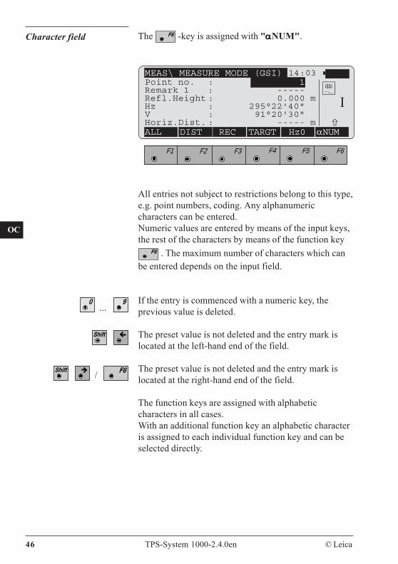
All entries not subject to restrictions belong to this type,e.g. point numbers, coding. Any alphanumericcharacters can be entered.Numeric values are entered by means of the input keys,the rest of the characters by means of the function key
. The maximum number of characters which canbe entered depends on the input field.
If the entry is commenced with a numeric key, theprevious value is deleted.
The preset value is not deleted and the entry mark islocated at the left-hand end of the field.
The preset value is not deleted and the entry mark islocated at the right-hand end of the field.
The function keys are assigned with alphabeticcharacters in all cases.With an additional function key an alphabetic characteris assigned to each individual function key and can beselected directly.
Character field The -key is assigned with "αααααNUM".
F1 F2 F3 F4 F5 F6
MEAS\ MEASURE MODE (GSI) 14:03Point no. : 1Remark 1 : -----Refl.Height : 0.000 mHz : 295°22'40"V : 91°20'30"Horiz.Dist. : ----- mALL DIST REC TARGT Hz0 αNUM
I
...
/
© Leica TPS-System 1000-2.4.0en 47
BK
CO
IN
ID
PM
FS
SC
OC
IO
AR
RC
EG
CA
CT
BC
DF
SD
TS
IX
14:03
A B C D E INS
F1 F2 F3 F4 F5 F6
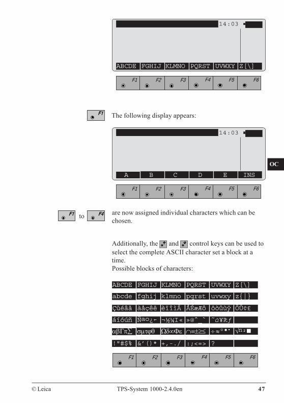
are now assigned individual characters which can bechosen.
The following display appears:
14:03
ABCDE FGHIJ KLMNO PQRST UVWXY Z[\]
F1 F2 F3 F4 F5 F6
Additionally, the and control keys can be used toselect the complete ASCII character set a block at atime.Possible blocks of characters:
ABCDE FGHIJ KLMNO PQRST UVWXY Z[\]
abcde fghij klmno pqrst uvwxy z{|}
Çüéâä àåçêë èïîìÄ ÅÉæÆô öòûùÿ ÖÜ¢£
áíóúñ Ñao¿ ¬½¼I« »@ˆ_` ˜ ¥Ptƒ
αβΓπ∑ σμτϕθ Ωδ∞Φε ∩≡±≥≤ ÷ ≈ ° • • √n²
!"#$% &’()* +,-./ :;<=> ?
F1 F2 F3 F4 F5 F6
to
48 TPS-System 1000-2.4.0en © Leica
BK
CO
IN
ID
PM
FS
SC
OC
IO
AR
RC
EG
CA
CT
BC
DF
SD
TS
IX
• Insert mode
If the entry mark is at the right-hand end of the inputfield, the new character will be appended to the existingone.If the entry mark is at another position in the input field,the character will be written over.
"INS" is assigned to the -key if a function keywas previously used to select an alphanumeric block.The and control keys can be used to move theentry mark over a digit or character before which acharacter can now be inserted. The character is alwaysinserted before the cursor.
In a numeric field the insert mode is also called with . The insert mode remains active until it is
deactivated with or until quitting the field.
© Leica TPS-System 1000-2.4.0en 49
BK
CO
IN
ID
PM
FS
SC
OC
IO
AR
RC
EG
CA
CT
BC
DF
SD
TS
IX
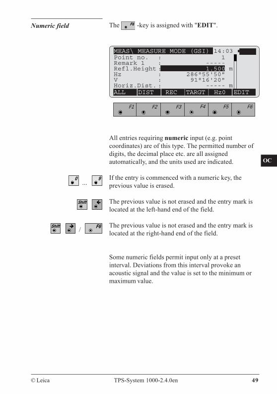
Numeric field The -key is assigned with "EDIT".
F1 F2 F3 F4 F5 F6
All entries requiring numeric input (e.g. pointcoordinates) are of this type. The permitted number ofdigits, the decimal place etc. are all assignedautomatically, and the units used are indicated.
If the entry is commenced with a numeric key, theprevious value is erased.
The previous value is not erased and the entry mark islocated at the left-hand end of the field.
The previous value is not erased and the entry mark islocated at the right-hand end of the field.
Some numeric fields permit input only at a presetinterval. Deviations from this interval provoke anacoustic signal and the value is set to the minimum ormaximum value.
MEAS\ MEASURE MODE (GSI) 14:03
ALL DIST REC TARGT Hz0 EDIT
Point no. : 1Remark 1 : -----Refl.Height : 1.500 mHz : 286°55'50"V : 91°16'20"Horiz.Dist. : ----- m
...
/
50 TPS-System 1000-2.4.0en © Leica
BK
CO
IN
ID
PM
FS
SC
OC
IO
AR
RC
EG
CA
CT
BC
DF
SD
TS
IX
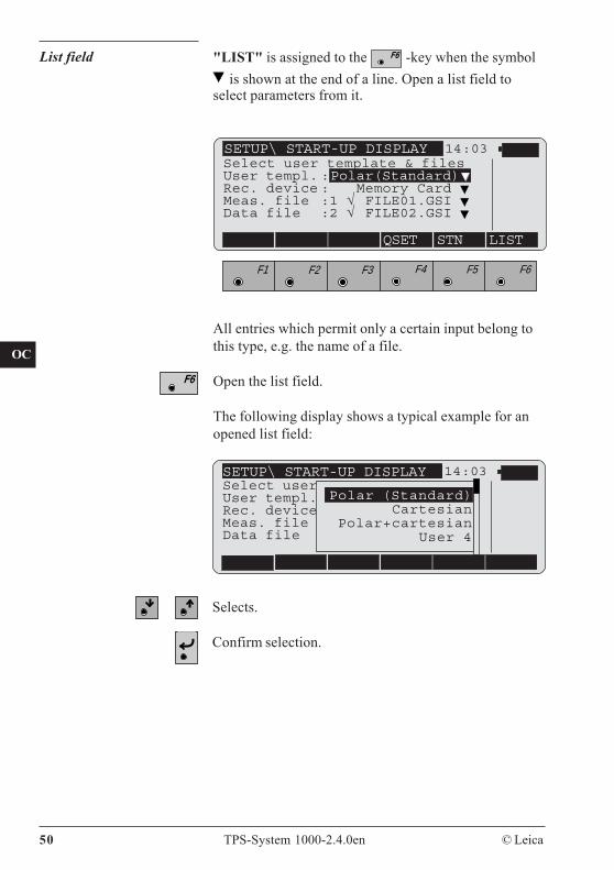
All entries which permit only a certain input belong tothis type, e.g. the name of a file.
Open the list field.
The following display shows a typical example for anopened list field:
List field "LIST" is assigned to the -key when the symbol is shown at the end of a line. Open a list field to
select parameters from it.
14:03
QSET STN LIST
F1 F2 F3 F4 F5 F6
SETUP\ START-UP DISPLAYSelect user template & filesUser templ. :Polar(Standard)Rec. device : Memory Card Meas. file :1 √ FILE01.GSI Data file :2 √ FILE02.GSI
SETUP\ START-UP DISPLAY 14:03Select userUser templ.Rec. deviceMeas. fileData file
Polar (Standard)Cartesian
Polar+cartesianUser 4
Selects.
Confirm selection.
© Leica TPS-System 1000-2.4.0en 51
BK
CO
IN
ID
PM
FS
SC
OC
IO
AR
RC
EG
CA
CT
BC
DF
SD
TS
IX
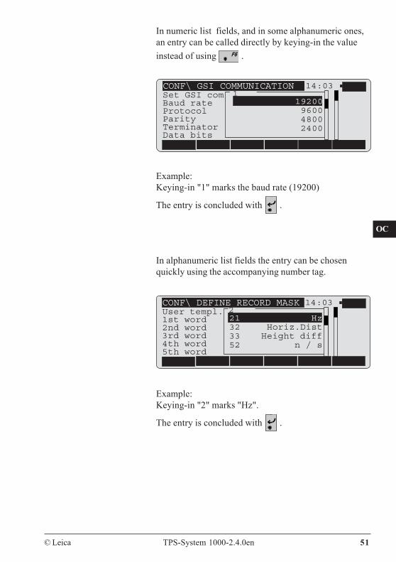
In numeric list fields, and in some alphanumeric ones,an entry can be called directly by keying-in the valueinstead of using .
CONF\ DEFINE RECORD MASKUser templ.1st word2nd word3rd word4th word5th word
21 Hz32 Horiz.Dist33 Height diff52 n / s
14:03
CONF\ GSI COMMUNICATIONSet GSI comBaud rateProtocolParityTerminatorData bits
19200960048002400
14:03
Example:Keying-in "1" marks the baud rate (19200)
The entry is concluded with .
In alphanumeric list fields the entry can be chosenquickly using the accompanying number tag.
1
Example:Keying-in "2" marks "Hz".
The entry is concluded with .
2
52 TPS-System 1000-2.4.0en © Leica
BK
CO
IN
ID
PM
FS
SC
OC
IO
AR
RC
EG
CA
CT
BC
DF
SD
TS
IX
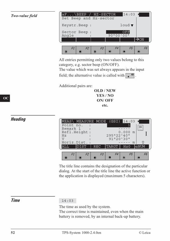
Two-value field aF...\BEEP / HZ-SECTOR 14:03
ON
F1 F2 F3 F4 F5 F6
Set Beep and Hz-sector
Keystr.Beep : loud
Sector Beep : OFFAngle : 90°00'00"
All entries permitting only two values belong to thiscategory, e.g. sector beep (ON/OFF).The value which was set always appears in the inputfield; the alternative value is called with .
Additional pairs are:OLD / NEW
YES / NOON/ OFF
etc.
Heading
F1 F2 F3 F4 F5 F6
The title line contains the designation of the particulardialog. At the start of the title line the active function orthe application is displayed (maximum 5 characters).
The time as used by the system.The correct time is maintained, even when the mainbattery is removed, by an internal back-up battery.
Time 14:03
MEAS\ MEASURE MODE (GSI) 14:03Point no. : 1Remark 1 : -----Refl.Height : 0.000 mHz : 295°22'40"V : 91°20'30"Horiz.Dist. : ----- mALL DIST REC TARGT Hz0 αNUM
I
© Leica TPS-System 1000-2.4.0en 53
BK
CO
IN
ID
PM
FS
SC
OC
IO
AR
RC
EG
CA
CT
BC
DF
SD
TS
IX
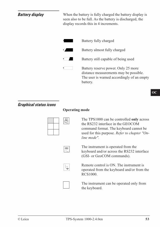
Battery display When the battery is fully charged the battery display isseen also to be full. As the battery is discharged, thedisplay records this in 4 increments.
Battery fully charged
Battery almost fully charged
Battery still capable of being used
Battery reserve power. Only 25 moredistance measurements may be possible.The user is warned accordingly of an emptybattery.
Graphical status icons
The TPS1000 can be controlled only acrossthe RS232 interface in the GEOCOMcommand format. The keyboard cannot beused for this purpose. Refer to chapter "On-line mode".
The instrument is operated from thekeyboard and/or across the RS232 interface(GSI- or GeoCOM commands).
Remote control is ON. The instrument isoperated from the keyboard and/or from theRCS1000.
The instrument can be operated only fromthe keyboard.
Operating mode
54 TPS-System 1000-2.4.0en © Leica
BK
CO
IN
ID
PM
FS
SC
OC
IO
AR
RC
EG
CA
CT
BC
DF
SD
TS
IX
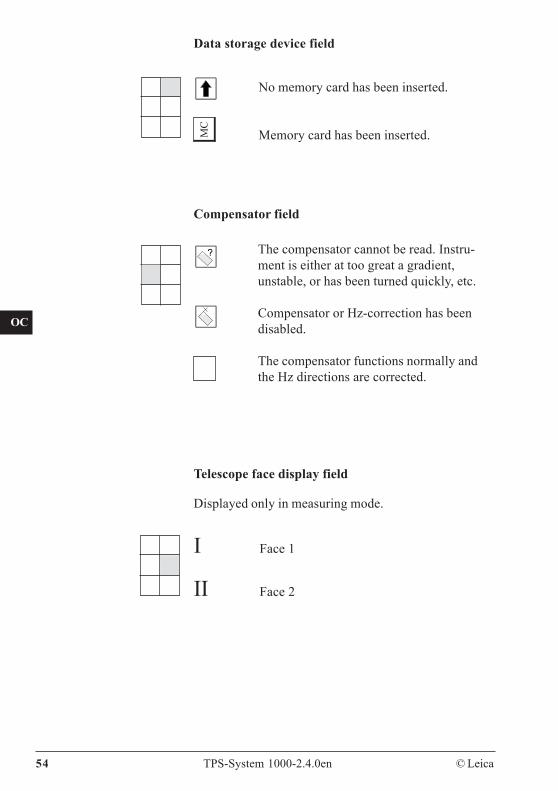
Compensator field
The compensator cannot be read. Instru-ment is either at too great a gradient,unstable, or has been turned quickly, etc.
Compensator or Hz-correction has beendisabled.
The compensator functions normally andthe Hz directions are corrected.
Data storage device field
MC
No memory card has been inserted.
Memory card has been inserted.
Displayed only in measuring mode.
Telescope face display field
I Face 1
II Face 2
© Leica TPS-System 1000-2.4.0en 55
BK
CO
IN
ID
PM
FS
SC
OC
IO
AR
RC
EG
CA
CT
BC
DF
SD
TS
IX
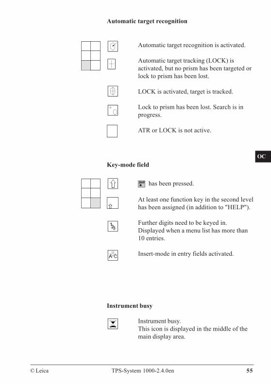
Automatic target recognition
Key-mode field
Automatic target recognition is activated.
Automatic target tracking (LOCK) isactivated, but no prism has been targeted orlock to prism has been lost.
LOCK is activated, target is tracked.
Lock to prism has been lost. Search is inprogress.
ATR or LOCK is not active.
Instrument busy.This icon is displayed in the middle of themain display area.
Instrument busy
has been pressed.
At least one function key in the second levelhas been assigned (in addition to "HELP").
Further digits need to be keyed in.Displayed when a menu list has more than10 entries.
Insert-mode in entry fields activated.
56 TPS-System 1000-2.4.0en © Leica
BK
CO
IN
ID
PM
FS
SC
OC
IO
AR
RC
EG
CA
CT
BC
DF
SD
TS
IX
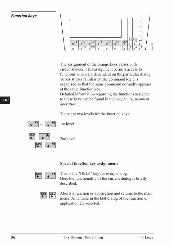
Function keys
The assignment of the orange keys varies withcircumstances. This assignment permits access tofunctions which are dependent on the particular dialog.To assist user familiarity, the command logic isorganized so that the same command normally appearsat the same function key.Detailed information regarding the functions assignedto these keys can be found in the chapter "Instrumentoperation".
There are two levels for the function keys:
1st level
2nd level
Special function key assignments
This is the "HELP" key for every dialog.Here the functionality of the current dialog is brieflydescribed.
Aborts a function or application and returns to the mainmenu. All entries in the last dialog of the function orapplication are rejected.
1000
Z03
F1 F2 F3 F4 F5 F6 Shift
...
...
© Leica TPS-System 1000-2.4.0en 57
BK
CO
IN
ID
PM
FS
SC
OC
IO
AR
RC
EG
CA
CT
BC
DF
SD
TS
IX
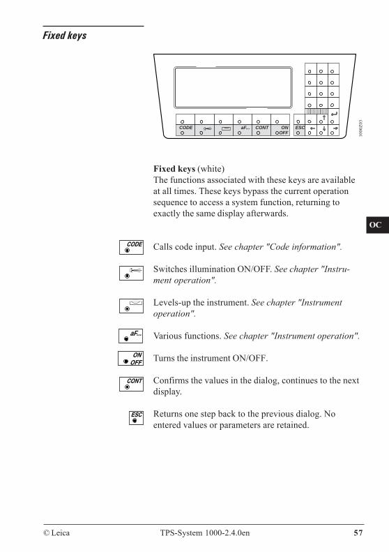
Fixed keys
1000
Z03
CODE aF... CONT ON ESCOFF
Fixed keys (white)The functions associated with these keys are availableat all times. These keys bypass the current operationsequence to access a system function, returning toexactly the same display afterwards.
Calls code input. See chapter "Code information".
Switches illumination ON/OFF. See chapter "Instru-ment operation".
Levels-up the instrument. See chapter "Instrumentoperation".
Various functions. See chapter "Instrument operation".
Turns the instrument ON/OFF.
Confirms the values in the dialog, continues to the nextdisplay.
Returns one step back to the previous dialog. Noentered values or parameters are retained.
aF...
58 TPS-System 1000-2.4.0en © Leica
BK
CO
IN
ID
PM
FS
SC
OC
IO
AR
RC
EG
CA
CT
BC
DF
SD
TS
IX
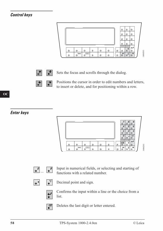
...
Control keys
Sets the focus and scrolls through the dialog.
Positions the cursor in order to edit numbers and letters,to insert or delete, and for positioning within a row.
1000
Z03
Enter keys
1000
Z03
7 8 9
4 5 6
1 2 3
0 • +/-
CE
Input in numerical fields, or selecting and starting offunctions with a related number.
Decimal point and sign.
Confirms the input within a line or the choice from alist.
Deletes the last digit or letter entered.
© Leica TPS-System 1000-2.4.0en 59
BK
CO
IN
ID
PM
FS
SC
OC
IO
AR
RC
EG
CA
CT
BC
DF
SD
TS
IX
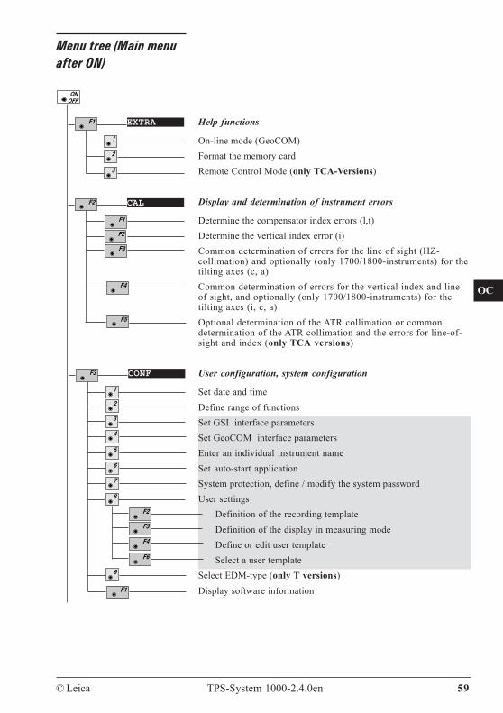
Menu tree (Main menuafter ON)
EXTRA
CAL
Help functions
On-line mode (GeoCOM)Format the memory cardRemote Control Mode (only TCA-Versions)
Display and determination of instrument errors
Determine the compensator index errors (l,t)Determine the vertical index error (i)Common determination of errors for the line of sight (HZ-collimation) and optionally (only 1700/1800-instruments) for thetilting axes (c, a)Common determination of errors for the vertical index and lineof sight, and optionally (only 1700/1800-instruments) for thetilting axes (i, c, a)Optional determination of the ATR collimation or commondetermination of the ATR collimation and the errors for line-of-sight and index (only TCA versions)
User configuration, system configuration
Set date and timeDefine range of functionsSet GSI interface parametersSet GeoCOM interface parametersEnter an individual instrument nameSet auto-start applicationSystem protection, define / modify the system passwordUser settings
Definition of the recording templateDefinition of the display in measuring modeDefine or edit user templateSelect a user template
Select EDM-type (only T versions)Display software information
CONF
8
60 TPS-System 1000-2.4.0en © Leica
BK
CO
IN
ID
PM
FS
SC
OC
IO
AR
RC
EG
CA
CT
BC
DF
SD
TS
IX
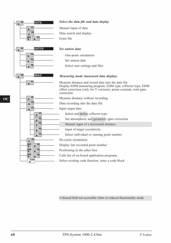
DATA
SETUP
MEAS
Coloured field not accessible when in reduced functionality mode
Select the data file and data display
Manual input of dataData search and displayErase file
Set station data
One-point orientationSet station dataSelect user settings and files
Measuring mode (measured data display)
Measure distance and record data into the data fileDisplay EDM measuring program, EDM type, reflector type, EDMoffset correction (only for T versions), prism constant, total ppmcorrectionMeasure distance without recordingData recording into the data fileInput target data
Select and define reflector typeSet atmospheric and geometric ppm correctionManual input of a horizontal distanceInput of target eccentricitySelect individual or running point number
Hz-circle orientationDisplay last recorded point numberPositioning in the other faceCalls list of on-board application programsSelect existing code function, enter a code block
CO
IN
ID
PM
FS
SC
OC
IO
AR
RC
EG
CA
CT
BC
DF
SD
TS
IX
© Leica TPS-System 1000-2.4.0en 61
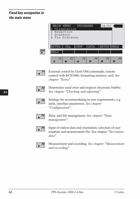
Main menu After the instrument has been switched on, theinstrument model and software version are brieflydisplayed. The instrument carries out a system test andthen engages the main menu.The special significance of the main menu is that allfixed system functions and all loadable applications canbe started from it, with the exception of the CODEfunction, which can be called from any dialog whichpermits data to be stored.The following overview indicates the assignment of thevarious functions to the function keys of the main menuand to the fixed keys.
Instrument operation
62 TPS-System 1000-2.4.0en © Leica
CO
IN
ID
PM
FS
SC
OC
IO
AR
RC
EG
CA
CT
BC
DF
SD
TS
IX
Fixed-key occupation inthe main menu
External control by GeoCOM commands; remotecontrol with RCS1000; formatting memory card. Seechapter "Extra".
Determines axial error and inspects electronic bubble.See chapter "Checking and adjusting".
Settings for accommodating to user requirements, e.g.units, interface parameters. See chapter"Configuration".
Data- and file management. See chapter "Datamanagement".
Input of station data and orientation, selection of usertemplate and measurement file. See chapter "Set stationdata".
Measurement and recording. See chapter "Measurementand recording".
MAIN MENU : PROGRAMS 14:031 Orientation2 Resection3 Stakeout4 Tie Distance
EXTRA CAL CONF DATA SETUP MEAS
F1 F2 F3 F4 F5 F6
HELP
CO
IN
ID
PM
FS
SC
OC
IO
AR
RC
EG
CA
CT
BC
DF
SD
TS
IX
© Leica TPS-System 1000-2.4.0en 63
Fixed-key occupation
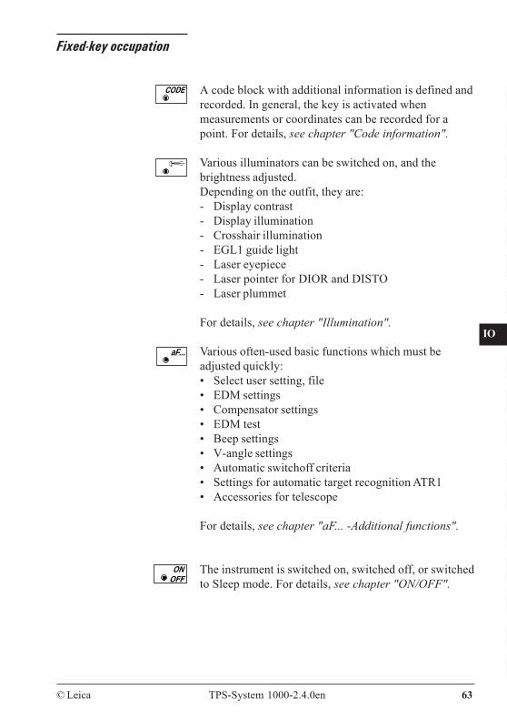
A code block with additional information is defined andrecorded. In general, the key is activated whenmeasurements or coordinates can be recorded for apoint. For details, see chapter "Code information".
Various illuminators can be switched on, and thebrightness adjusted.Depending on the outfit, they are:- Display contrast- Display illumination- Crosshair illumination- EGL1 guide light- Laser eyepiece- Laser pointer for DIOR and DISTO- Laser plummet
For details, see chapter "Illumination".
Various often-used basic functions which must beadjusted quickly:• Select user setting, file• EDM settings• Compensator settings• EDM test• Beep settings• V-angle settings• Automatic switchoff criteria• Settings for automatic target recognition ATR1• Accessories for telescope
For details, see chapter "aF... -Additional functions".
The instrument is switched on, switched off, or switchedto Sleep mode. For details, see chapter "ON/OFF".
aF...
64 TPS-System 1000-2.4.0en © Leica
CO
IN
ID
PM
FS
SC
OC
IO
AR
RC
EG
CA
CT
BC
DF
SD
TS
IX
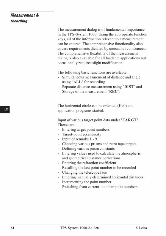
Measurement &recording
The measurement dialog is of fundamental importancein the TPS-System 1000. Using the appropriate functionkeys, all of the information relevant to a measurementcan be entered. The comprehensive functionality alsocovers requirements dictated by unusual circumstances.The comprehensive flexibility of the measurementdialog is also available for all loadable applications butoccasionally requires slight modification.
The following basic functions are available:- Simultaneous measurement of distance and angle,
using "ALL" for recording- Separate distance measurement using "DIST" and- Storage of the measurement "REC".
The horizontal circle can be oriented (Hz0) andapplication programs started.
Input of various target point data under "TARGT".Therse are:- Entering target point numbers- Target-point eccentricity- Input of remarks 1 - 9- Choosing various prisms and retro tape targets- Defining various prism constants- Entering values used to calculate the atmospheric
and geometrical distance corrections- Entering the refraction coefficient- Recalling the last point number to be recorded- Changing the telescope face- Entering manually-determined horizontal distances- Incrementing the point number- Switching from current- to other point numbers.
CO
IN
ID
PM
FS
SC
OC
IO
AR
RC
EG
CA
CT
BC
DF
SD
TS
IX
© Leica TPS-System 1000-2.4.0en 65
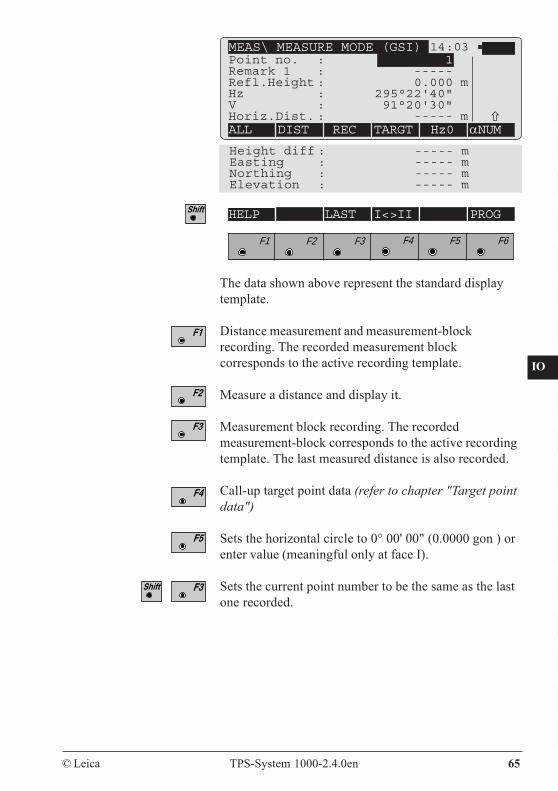
The data shown above represent the standard displaytemplate.
Distance measurement and measurement-blockrecording. The recorded measurement blockcorresponds to the active recording template.
Measure a distance and display it.
Measurement block recording. The recordedmeasurement-block corresponds to the active recordingtemplate. The last measured distance is also recorded.
Call-up target point data (refer to chapter "Target pointdata")
Sets the horizontal circle to 0° 00' 00" (0.0000 gon ) orenter value (meaningful only at face I).
Sets the current point number to be the same as the lastone recorded.
MEAS\ MEASURE MODE (GSI) 14:03Point no. : 1Remark 1 : -----Refl.Height : 0.000 mHz : 295°22'40"V : 91°20'30"Horiz.Dist. : ----- mALL DIST REC TARGT Hz0 αNUM
Height diff : ----- mEasting : ----- mNorthing : ----- mElevation : ----- m
F1 F2 F3 F4 F5 F6
HELP LAST I<>II PROG

66 TPS-System 1000-2.4.0en © Leica
CO
IN
ID
PM
FS
SC
OC
IO
AR
RC
EG
CA
CT
BC
DF
SD
TS
IX
Change telescope face. ΔHz and ΔV are displayed. Theinstrument should be turned until the differential valuesare both "0.000", and then the same target point appearsin the telescope. This procedure is useful in conditionsof poor visibility.Motorized theodolites turn automatically to theother telescope face (TM/TCM- and TCA versions).
Calls the application programs dialog. From here, theapplication programs can be started.
Reflectorheight
Heightdifference
V Hz
Horizontal distanceInstrumentheight
Slope distance
Hz =
0
Explanation of the elements of measurement
Hz = Horizontal angleV = Vertical angle
1000
QS3
5
CO
IN
ID
PM
FS
SC
OC
IO
AR
RC
EG
CA
CT
BC
DF
SD
TS
IX
© Leica TPS-System 1000-2.4.0en 67
Measuring distances andangles together
MEAS\ MEASURE MODE (GSI) 14:03
ALL DIST REC TARGT Hz0 αNUMHeight diff : 23.650 mEasting : 76.943 mNorthing : 1902.437 mElevation : 523.650 m
Point no. : 100Remark 1 : newRefl.Height : 1.500 mHz : 214°52'45"V : 85°25'17"Horiz.Dist. : 100.251 m
F1 F2 F3 F4 F5 F6
HELP LAST I<>II PROG
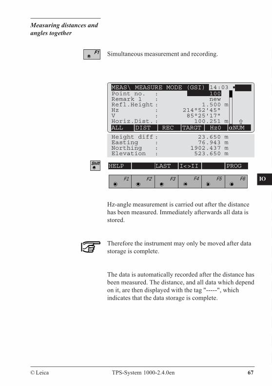
Hz-angle measurement is carried out after the distancehas been measured. Immediately afterwards all data isstored.
Therefore the instrument may only be moved after datastorage is complete.
The data is automatically recorded after the distance hasbeen measured. The distance, and all data which dependon it, are then displayed with the tag "-----", whichindicates that the data storage is complete.
Simultaneous measurement and recording.
68 TPS-System 1000-2.4.0en © Leica
CO
IN
ID
PM
FS
SC
OC
IO
AR
RC
EG
CA
CT
BC
DF
SD
TS
IX
Measuring distances andangles separately
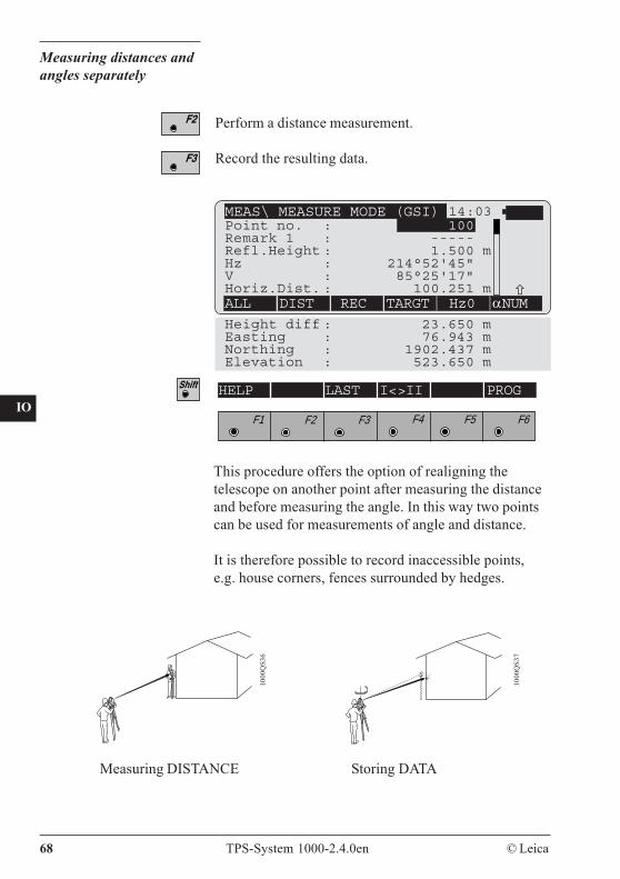
Perform a distance measurement.
Record the resulting data.
1000
QS3
6
1000
QS3
7
MEAS\ MEASURE MODE (GSI) 14:03
ALL DIST REC TARGT Hz0 αNUMHeight diff : 23.650 mEasting : 76.943 mNorthing : 1902.437 mElevation : 523.650 m
Point no. : 100Remark 1 : -----Refl.Height : 1.500 mHz : 214°52'45"V : 85°25'17"Horiz.Dist. : 100.251 m
F1 F2 F3 F4 F5 F6
HELP LAST I<>II PROG
Storing DATAMeasuring DISTANCE
This procedure offers the option of realigning thetelescope on another point after measuring the distanceand before measuring the angle. In this way two pointscan be used for measurements of angle and distance.
It is therefore possible to record inaccessible points,e.g. house corners, fences surrounded by hedges.
CO
IN
ID
PM
FS
SC
OC
IO
AR
RC
EG
CA
CT
BC
DF
SD
TS
IX
© Leica TPS-System 1000-2.4.0en 69
For calculations which depend on distance, the V-angleafter completion of the distance measurement is used,along with the current Hz-direction. Consequently,calculated heights and height differences are retainedand the coordinates for easting and northing whichcorrespond to the new Hz direction are recalculatedusing the last-measured distance.
The V-angle displayed corresponds to the position ofthe telescope on completion of the distancemeasurement. The V-angle is not altered until themeasurement is recorded, the last recorded pointnumber is recalled, a new distance is measured,or is pressed.
When distances, heights, or height differences aredisplayed as empty fields (i.e. -----), the V-angle iscontinuously displayed and updated.
If, after the distance has been measured, changes aremade to the target-point data which have an influenceon the distance measured or on the height and heightdifference (e.g. ppm, prism constant, reflector height,refraction coefficient), the dependent data will becorrespondingly verified.
70 TPS-System 1000-2.4.0en © Leica
CO
IN
ID
PM
FS
SC
OC
IO
AR
RC
EG
CA
CT
BC
DF
SD
TS
IX
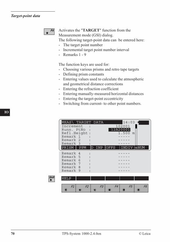
Target-point data
Activates the "TARGET" function from theMeasurement mode (GSI) dialog.The following target-point data can be entered here:- The target point number- Incremental target point number interval- Remarks 1 - 9
The function keys are used for:- Choosing various prisms and retro tape targets- Defining prism constants- Entering values used to calculate the atmospheric
and geometrical distance corrections- Entering the refraction coefficient- Entering manually-measured horizontal distances- Entering the target-point eccentricity- Switching from current- to other point numbers.
MEAS\ TARGET DATA 14:03
PRISM PPM D INP OFFS INDIV αNUMRemark 4 : -----Remark 5 : -----Remark 6 : -----Remark 7 : -----Remark 8 : -----Remark 9 : -----
Increment : 102001Runn. PtNo : 12A20001Refl.Height : 1.500 mRemark 1 : -----Remark 2 : -----Remark 3 : -----
F1 F2 F3 F4 F5 F6
HELP
CO
IN
ID
PM
FS
SC
OC
IO
AR
RC
EG
CA
CT
BC
DF
SD
TS
IX
© Leica TPS-System 1000-2.4.0en 71
Choose the prism from 6 possibilities : Leica circularprism, retro tape target (not in the T/TM versions),Leica 360° prism, 3 user-defined prisms.
Setting the atmospheric ppm and the geometric ppm(height and projection) and the refraction coefficient.
Enter a manually-measured horizontal distance.
Enter the data for an eccentric target point.
Change between individual and running point number.
Supplementary information entered (remarks, type ofpoint, topological data etc.) can be stored under"Remarks" .
The remarks must be defined in the recording template.They are stored along with every measurement. Thevalue is retained until it is changed.
If the remarks are defined in the display template, theycan be entered directly in the measurement dialog.
Additional information can also be stored in codeblocks instead of under "Remarks". For detailedinformation about the use of additional information,refer to the chapters "Code information" and "Dataformat".
Remarks
72 TPS-System 1000-2.4.0en © Leica
CO
IN
ID
PM
FS
SC
OC
IO
AR
RC
EG
CA
CT
BC
DF
SD
TS
IX
Incrementing pointnumbers
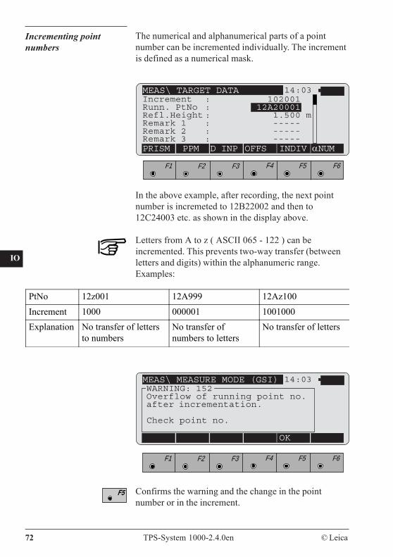
MEAS\ TARGET DATA 14:03
PRISM PPM D INP OFFS INDIV αNUM
Increment : 102001Runn. PtNo : 12A20001Refl.Height : 1.500 mRemark 1 : -----Remark 2 : -----Remark 3 : -----
F1 F2 F3 F4 F5 F6
In the above example, after recording, the next pointnumber is incremeted to 12B22002 and then to12C24003 etc. as shown in the display above.
Letters from A to z ( ASCII 065 - 122 ) can beincremented. This prevents two-way transfer (betweenletters and digits) within the alphanumeric range.Examples:
PtNo 12z001 12A999 12Az100Increment 1000 000001 1001000Explanation No transfer of letters
to numbersNo transfer ofnumbers to letters
No transfer of letters
MEAS\ MEASURE MODE (GSI) 14:03
OK
WARNING: 152Overflow of running point no.after incrementation.
Check point no.
F1 F2 F3 F4 F5 F6
The numerical and alphanumerical parts of a pointnumber can be incremented individually. The incrementis defined as a numerical mask.
Confirms the warning and the change in the pointnumber or in the increment.
CO
IN
ID
PM
FS
SC
OC
IO
AR
RC
EG
CA
CT
BC
DF
SD
TS
IX
© Leica TPS-System 1000-2.4.0en 73
Set and define prisms
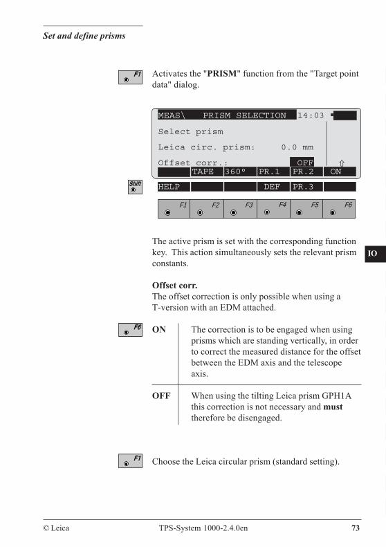
Activates the "PRISM" function from the "Target pointdata" dialog.
FOLIE 360° PR.1 PR.2 EIN
14:03
HELP DEF PR.3
F1 F2 F3 F4 F5 F6
MEAS\ PRISM SELECTION
TAPE 360° PR.1 PR.2 ON
The active prism is set with the corresponding functionkey. This action simultaneously sets the relevant prismconstants.
Offset corr.The offset correction is only possible when using aT-version with an EDM attached.
ON The correction is to be engaged when usingprisms which are standing vertically, in orderto correct the measured distance for the offsetbetween the EDM axis and the telescopeaxis.
OFF When using the tilting Leica prism GPH1Athis correction is not necessary and musttherefore be disengaged.
Choose the Leica circular prism (standard setting).
Select prism
Leica circ. prism: 0.0 mm
Offset corr.: OFF
74 TPS-System 1000-2.4.0en © Leica
CO
IN
ID
PM
FS
SC
OC
IO
AR
RC
EG
CA
CT
BC
DF
SD
TS
IX
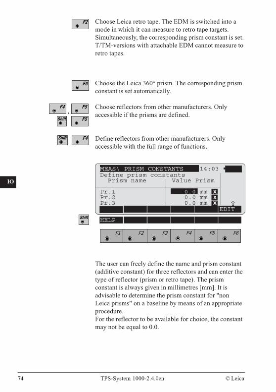
Choose Leica retro tape. The EDM is switched into amode in which it can measure to retro tape targets.Simultaneously, the corresponding prism constant is set.T/TM-versions with attachable EDM cannot measure toretro tapes.
Choose the Leica 360° prism. The corresponding prismconstant is set automatically.
Choose reflectors from other manufacturers. Onlyaccessible if the prisms are defined.
Define reflectors from other manufacturers. Onlyaccessible with the full range of functions.
The user can freely define the name and prism constant(additive constant) for three reflectors and can enter thetype of reflector (prism or retro tape). The prismconstant is always given in millimetres [mm]. It isadvisable to determine the prism constant for "nonLeica prisms" on a baseline by means of an appropriateprocedure.For the reflector to be available for choice, the constantmay not be equal to 0.0.
EDITFOLIE 360° PR.1 PR.2 EIN
14:03
HELP
F1 F2 F3 F4 F5 F6
EDIT
MEAS\ PRISM CONSTANTSDefine prism constants Prism name Value Prism
Pr.1 0.0 mm xPr.2 0.0 mm xPr.3 0.0 mm x
,
CO
IN
ID
PM
FS
SC
OC
IO
AR
RC
EG
CA
CT
BC
DF
SD
TS
IX
© Leica TPS-System 1000-2.4.0en 75
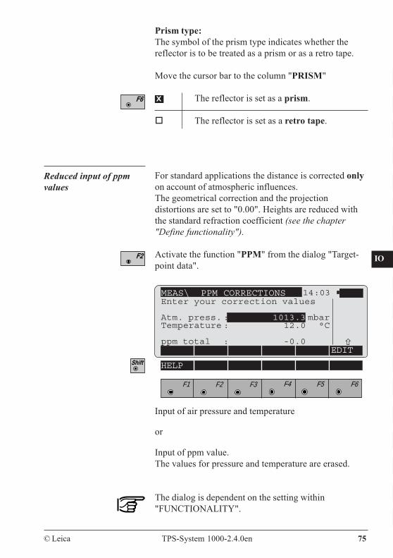
Prism type:The symbol of the prism type indicates whether thereflector is to be treated as a prism or as a retro tape.
Move the cursor bar to the column "PRISM"
x The reflector is set as a prism.
The reflector is set as a retro tape.
FOLIE 360° PR.1 PR.2 EIN
14:03
HELP
F1 F2 F3 F4 F5 F6
MEAS\ PPM CORRECTIONS
EDIT
Enter your correction values
Atm. press. : 1013.3 mbarTemperature : 12.0 °C
ppm total : -0.0
Reduced input of ppmvalues
For standard applications the distance is corrected onlyon account of atmospheric influences.The geometrical correction and the projectiondistortions are set to "0.00". Heights are reduced withthe standard refraction coefficient (see the chapter"Define functionality").
Activate the function "PPM" from the dialog "Target-point data".
Input of air pressure and temperature
or
Input of ppm value.The values for pressure and temperature are erased.
The dialog is dependent on the setting within"FUNCTIONALITY".
76 TPS-System 1000-2.4.0en © Leica
CO
IN
ID
PM
FS
SC
OC
IO
AR
RC
EG
CA
CT
BC
DF
SD
TS
IX
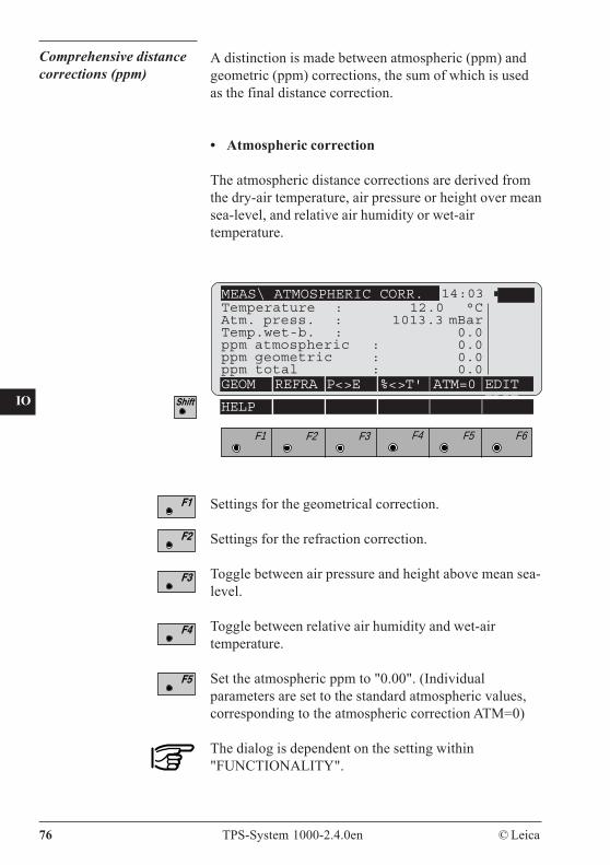
Comprehensive distancecorrections (ppm)
A distinction is made between atmospheric (ppm) andgeometric (ppm) corrections, the sum of which is usedas the final distance correction.
• Atmospheric correction
The atmospheric distance corrections are derived fromthe dry-air temperature, air pressure or height over meansea-level, and relative air humidity or wet-airtemperature.
MEAS\ ATMOSPHERIC CORR. 14:03Temperature : 12.0 °CAtm. press. : 1013.3 mBarTemp.wet-b. : 0.0ppm atmospheric : 0.0ppm geometric : 0.0ppm total : 0.0GEOM REFRA P<>E %<>T' ATM=0 EDIT
EDITHELP
F1 F2 F3 F4 F5 F6
Settings for the geometrical correction.
Settings for the refraction correction.
Toggle between air pressure and height above mean sea-level.
Toggle between relative air humidity and wet-airtemperature.
Set the atmospheric ppm to "0.00". (Individualparameters are set to the standard atmospheric values,corresponding to the atmospheric correction ATM=0)
The dialog is dependent on the setting within"FUNCTIONALITY".
CO
IN
ID
PM
FS
SC
OC
IO
AR
RC
EG
CA
CT
BC
DF
SD
TS
IX
© Leica TPS-System 1000-2.4.0en 77
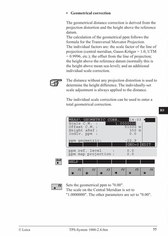
• Geometrical correction
The geometrical distance correction is derived from theprojection distortion and the height above the referencedatum.The calculation of the geometrical ppm follows theformula for the Transversal Mercator Projection.The individual factors are: the scale factor of the line ofprojection (central meridian, Gauss-Krüger = 1.0, UTM= 0.9996, etc.); the offset from the line of projection;the height above the reference datum (normally this isthe height above mean sea-level); and an additionalindividual scale correction.
The distance without any projection distortion is used todetermine the height difference. The individually-setscale adjustment is always applied to the distance.
The individual scale correction can be used to enter atotal geometrical correction.
MEAS\ GEOMETRIC CORR. 14:03
GEO=0 EDIT
Scale C.M. : 1.0000000Offset C.M. : 51000 mHeight aRef : 350 mIndiv. ppm : 0.0
ppm geometric: -22.9
ppm ref. level : 0.0ppm map projection : 0.0
HELP
F1 F2 F3 F4 F5 F6
Sets the geometrical ppm to "0.00".The scale on the Central Meridian is set to"1.0000000". The other parameters are set to "0.00".
78 TPS-System 1000-2.4.0en © Leica
CO
IN
ID
PM
FS
SC
OC
IO
AR
RC
EG
CA
CT
BC
DF
SD
TS
IX
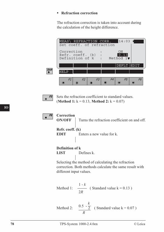
Sets the refraction coefficient to standard values.(Method 1: k = 0.13, Method 2: k = 0.07)
CorrectionON/OFF Turns the refraction coefficient on and off.
Refr. coeff. (k)EDIT Enters a new value for k.
Definition of kLIST Defines k.
Selecting the method of calculating the refractioncorrection. Both methods calculate the same result withdifferent input values.
• Refraction correction
The refraction correction is taken into account duringthe calculation of the height difference.
MEAS\ REFRACTION CORR. 14:03
DEFLT EDIT
HELP
F1 F2 F3 F4 F5 F6
Set coeff. of refraction
Correction : ONRefr. coeff. (k) : 0.13Definition of k : Method 1
1 - kMethod 1: ( Standard value k = 0.13 )
2R
0.5 - k
Method 2: 2 ( Standard value k = 0.07 ) R
CO
IN
ID
PM
FS
SC
OC
IO
AR
RC
EG
CA
CT
BC
DF
SD
TS
IX
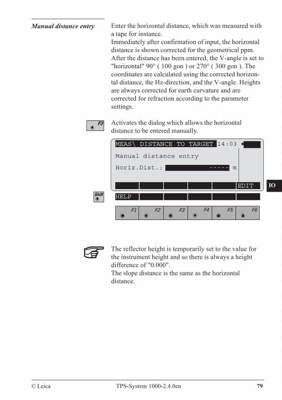
© Leica TPS-System 1000-2.4.0en 79
Manual distance entry Enter the horizontal distance, which was measured witha tape for instance.Immediately after confirmation of input, the horizontaldistance is shown corrected for the geometrical ppm.After the distance has been entered, the V-angle is set to"horizontal" 90° ( 100 gon ) or 270° ( 300 gon ). Thecoordinates are calculated using the corrected horizon-tal distance, the Hz-direction, and the V-angle. Heightsare always corrected for earth curvature and arecorrected for refraction according to the parametersettings.
Activates the dialog which allows the horizontaldistance to be entered manually.
MEAS\ DISTANCE TO TARGET 14:03
EDIT
HELP
F1 F2 F3 F4 F5 F6
Manual distance entry
Horiz.Dist.: ----- m
The reflector height is temporarily set to the value forthe instrument height and so there is always a heightdifference of "0.000".The slope distance is the same as the horizontaldistance.
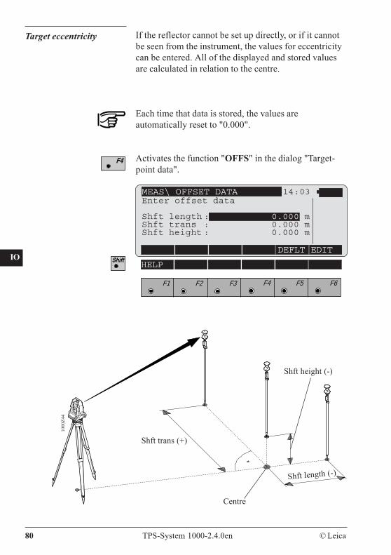
80 TPS-System 1000-2.4.0en © Leica
CO
IN
ID
PM
FS
SC
OC
IO
AR
RC
EG
CA
CT
BC
DF
SD
TS
IX
Target eccentricity If the reflector cannot be set up directly, or if it cannotbe seen from the instrument, the values for eccentricitycan be entered. All of the displayed and stored valuesare calculated in relation to the centre.
Each time that data is stored, the values areautomatically reset to "0.000".
Activates the function "OFFS" in the dialog "Target-point data".
MEAS\ OFFSET DATA 14:03
DEFLT EDIT
HELP
F1 F2 F3 F4 F5 F6
Enter offset data
Shft length : 0.000 mShft trans : 0.000 mShft height : 0.000 m
Centre
1000
Z44
Shft length (-)
Shft height (-)
Shft trans (+)
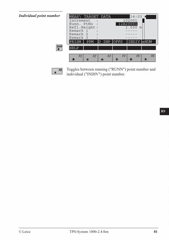
CO
IN
ID
PM
FS
SC
OC
IO
AR
RC
EG
CA
CT
BC
DF
SD
TS
IX
© Leica TPS-System 1000-2.4.0en 81
Individual point number
Toggles between running ("RUNN") point number andindividual ("INDIV") point number.
MEAS\ TARGET DATA 14:03
PRISM PPM D INP OFFS INDIV αNUM
Increment : 102001Runn. PtNo : 12A20001Refl.Height : 1.500 mRemark 1 : -----Remark 2 : -----Remark 3 : -----
F1 F2 F3 F4 F5 F6
HELP
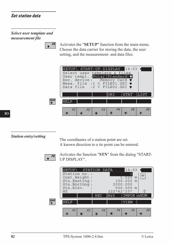
82 TPS-System 1000-2.4.0en © Leica
CO
IN
ID
PM
FS
SC
OC
IO
AR
RC
EG
CA
CT
BC
DF
SD
TS
IX
Set station data
Select user template andmeasurement file
F1 F2 F3 F4 F5 F6
HELP
14:03
ORI STAT LIST
SETUP\ START-UP DISPLAYSelect user template & filesUser templ. :Polar(Standard)Rec. device : Memory Card Meas. file :1 √ FILE01.GSI Data file :2 √ FILE02.GSI
Station entry/setting
SETUP\ STATION DATA 14:03
REC Hz0 IMPOR αNUM
F1 F2 F3 F4 F5 F6
HELP VIEW
Station no. : 1Inst.Height : 1.520 mStn.Easting : 100.000 mStn.Northng : 2000.000Stn.Elev. : 500.000 mHZ : 222°42'33"
Activates the "SETUP" function from the main menu.Choose the data carrier for storing the data, the usersetting, and the measurement- and data files.
The coordinates of a station point are set.A known direction to a tie point can be entered.
Activates the function "STN" from the dialog "START-UP DISPLAY".
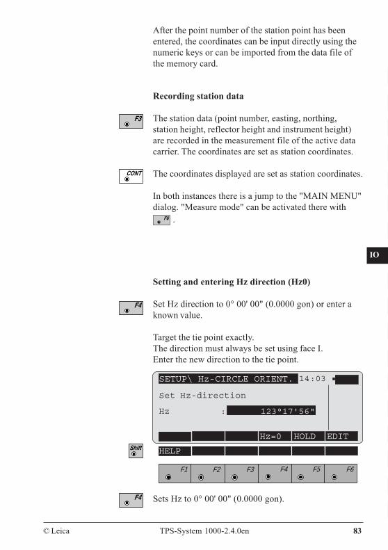
CO
IN
ID
PM
FS
SC
OC
IO
AR
RC
EG
CA
CT
BC
DF
SD
TS
IX
© Leica TPS-System 1000-2.4.0en 83
After the point number of the station point has beenentered, the coordinates can be input directly using thenumeric keys or can be imported from the data file ofthe memory card.
SETUP\ Hz-CIRCLE ORIENT. 14:03
Hz=0 HOLD EDIT
F1 F2 F3 F4 F5 F6
HELP
Setting and entering Hz direction (Hz0)
Set Hz direction to 0° 00' 00" (0.0000 gon) or enter aknown value.
Target the tie point exactly.The direction must always be set using face I.Enter the new direction to the tie point.
Recording station data
The station data (point number, easting, northing,station height, reflector height and instrument height)are recorded in the measurement file of the active datacarrier. The coordinates are set as station coordinates.
The coordinates displayed are set as station coordinates.
In both instances there is a jump to the "MAIN MENU"dialog. "Measure mode" can be activated there with
.
Sets Hz to 0° 00' 00" (0.0000 gon).
Set Hz-direction
Hz : 123°17'56"

84 TPS-System 1000-2.4.0en © Leica
CO
IN
ID
PM
FS
SC
OC
IO
AR
RC
EG
CA
CT
BC
DF
SD
TS
IX
Instead of entering a value, this can be set by turning theinstrument.
Secures the value (clamp the circle)
Target the tie point exactly.
Releases the circle.
This function is also activated from other dialogs inorder to enter the Hz direction.
Direct data searchAfter the complete point number has been entered, thecoordinates of the first data set (the search always startsat the beginning of the file) are accepted for theapplication. The data set found is generally notdisplayed and the appropriate application activates thesubsequent dialog.1
1 The dialog "STATION DATA" is an exception to thisrule and the coordinates there are displayed.
Import point data (Import function)
As well as the measuring mode, the function "Importpoint data" has a special significance, because it is alsoused in many applications. This function enables pointcoordinates to be read from the data file andtransferred to the application currently in use.
SETUP\ STATION DATA 14:03
REC Hz0 IMPOR αNUM
F1 F2 F3 F4 F5 F6
HELP VIEW
Station no. : 1Inst.Height : 1.520 mStn.Easting : 100.000 mStn.Northng : 2000.000Stn.Elev. : 500.000 mHZ : 222°42'33"
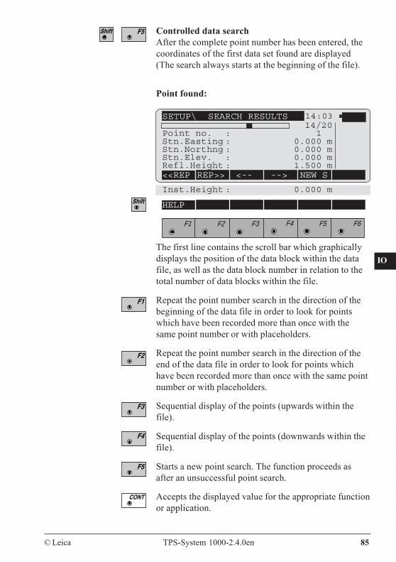
CO
IN
ID
PM
FS
SC
OC
IO
AR
RC
EG
CA
CT
BC
DF
SD
TS
IX
© Leica TPS-System 1000-2.4.0en 85
Controlled data searchAfter the complete point number has been entered, thecoordinates of the first data set found are displayed(The search always starts at the beginning of the file).
The first line contains the scroll bar which graphicallydisplays the position of the data block within the datafile, as well as the data block number in relation to thetotal number of data blocks within the file.
Repeat the point number search in the direction of thebeginning of the data file in order to look for pointswhich have been recorded more than once with thesame point number or with placeholders.
Repeat the point number search in the direction of theend of the data file in order to look for points whichhave been recorded more than once with the same pointnumber or with placeholders.
Sequential display of the points (upwards within thefile).
Sequential display of the points (downwards within thefile).
Starts a new point search. The function proceeds asafter an unsuccessful point search.
Accepts the displayed value for the appropriate functionor application.
Point found:
SETUP\ SEARCH RESULTS 14:03
<<REP REP>> <-- --> NEW S
14/20Point no. : 1Stn.Easting : 0.000 mStn.Northng : 0.000 mStn.Elev. : 0.000 mRefl.Height : 1.500 m
Inst.Height : 0.000 m
F1 F2 F3 F4 F5 F6
HELP
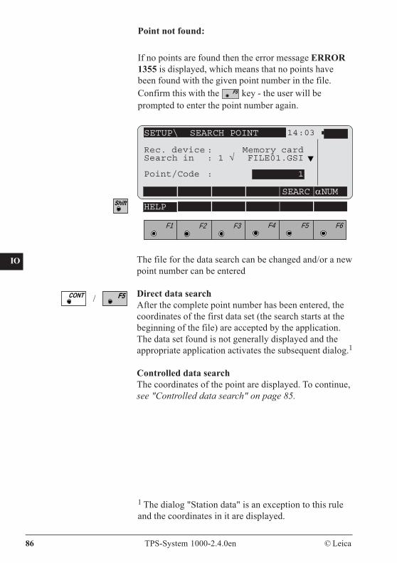
86 TPS-System 1000-2.4.0en © Leica
CO
IN
ID
PM
FS
SC
OC
IO
AR
RC
EG
CA
CT
BC
DF
SD
TS
IX
Point not found:
If no points are found then the error message ERROR1355 is displayed, which means that no points havebeen found with the given point number in the file.Confirm this with the key - the user will beprompted to enter the point number again.
SETUP\ SEARCH POINT 14:03
SEARC αNUM
F1 F2 F3 F4 F5 F6
HELP
Rec. device : Memory cardSearch in : 1 √ FILE01.GSI
Point/Code : 1
The file for the data search can be changed and/or a newpoint number can be entered
Direct data searchAfter the complete point number has been entered, thecoordinates of the first data set (the search starts at thebeginning of the file) are accepted by the application.The data set found is not generally displayed and theappropriate application activates the subsequent dialog.1
Controlled data searchThe coordinates of the point are displayed. To continue,see "Controlled data search" on page 85.
/
1 The dialog "Station data" is an exception to this ruleand the coordinates in it are displayed.
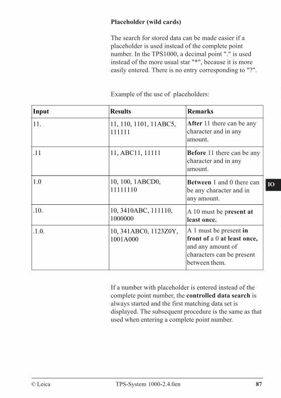
CO
IN
ID
PM
FS
SC
OC
IO
AR
RC
EG
CA
CT
BC
DF
SD
TS
IX
© Leica TPS-System 1000-2.4.0en 87
Placeholder (wild cards)
The search for stored data can be made easier if aplaceholder is used instead of the complete pointnumber. In the TPS1000, a decimal point "." is usedinstead of the more usual star "*", because it is moreeasily entered. There is no entry corresponding to "?".
Example of the use of placeholders:
Input Results Remarks
11. 11, 110, 1101, 11ABC5,111111
.11 11, ABC11, 11111
1.0 10, 100, 1ABCD0,11111110
.10. 10, 3410ABC, 111110,1000000
.1.0. 10, 341ABC0, 1123Z0Y,1001A000
If a number with placeholder is entered instead of thecomplete point number, the controlled data search isalways started and the first matching data set isdisplayed. The subsequent procedure is the same as thatused when entering a complete point number.
After 11 there can be anycharacter and in anyamount.
Before 11 there can be anycharacter and in anyamount.
Between 1 and 0 there canbe any character and inany amount.
A 10 must be present atleast once.A 1 must be present infront of a 0 at least once,and any amount ofcharacters can be presentbetween them.
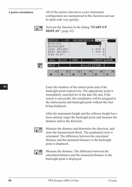
88 TPS-System 1000-2.4.0en © Leica
CO
IN
ID
PM
FS
SC
OC
IO
AR
RC
EG
CA
CT
BC
DF
SD
TS
IX
1-point orientation All of the entries relevant to a new instrumentconfiguration are summarized in this function and canbe dealt with very quickly.
Activate the function in the dialog "START-UPDISPLAY" (page 82).
Enter the numbers of the station point and of thebacksight point respectively. The appropriate point isimmediately searched for in the data file and, if thesearch is successful, the coordinates will be assigned tothe station point and backsight point without this factbeing displayed.
After the instrument height and the reflector height havebeen entered, target the backsight point and measure thedistance and/or the direction.
Measure the distance and determine the direction, andstore the measurement block. The graduated circle isorientated. The difference between the calculateddistance and the measured distance to the backsightpoint is displayed.
Measure the distance. The difference between thecalculated distance and the measured distance to thebacksight point is displayed.
F1 F2 F3 F4 F5 F6
HELP I<>II VIEW
14:03
ALL DIST REC INPUT αNUM
SETUP\ 1-PT. ORIENTATIONStation : 1Backsight : AInst.Height: 1.500 mRefl.Height: 1.000 mΔ Hz-Dist. : ----- m
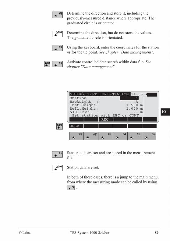
CO
IN
ID
PM
FS
SC
OC
IO
AR
RC
EG
CA
CT
BC
DF
SD
TS
IX
© Leica TPS-System 1000-2.4.0en 89
Determine the direction and store it, including thepreviously-measured distance where appropriate. Thegraduated circle is orientated.
Determine the direction, but do not store the values.The graduated circle is orientated.
Using the keyboard, enter the coordinates for the stationor for the tie point. See chapter "Data management".
Activate controlled data search within data file. Seechapter "Data management".
F1 F2 F3 F4 F5 F6
HELP
14:03
REC
SETUP\ 1-PT. ORIENTATION
Station data are set and are stored in the measurementfile.
Station data are set.
In both of these cases, there is a jump to the main menu,from where the measuring mode can be called by using
.
Station : 1Backsight : AInst.Height: 1.500 mRefl.Height: 1.000 mΔ Hz-Dist. : ----- m Set station with REC or CONT
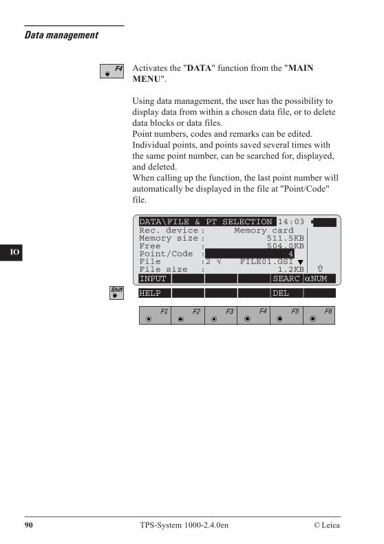
90 TPS-System 1000-2.4.0en © Leica
CO
IN
ID
PM
FS
SC
OC
IO
AR
RC
EG
CA
CT
BC
DF
SD
TS
IX
Data management
Activates the "DATA" function from the "MAINMENU".
Using data management, the user has the possibility todisplay data from within a chosen data file, or to deletedata blocks or data files.Point numbers, codes and remarks can be edited.Individual points, and points saved several times withthe same point number, can be searched for, displayed,and deleted.When calling up the function, the last point number willautomatically be displayed in the file at "Point/Code"file.
DATA\FILE & PT SELECTION 14:03
INPUT SEARC αNUM
F1 F2 F3 F4 F5 F6
HELP DEL
Rec. device : Memory cardMemory size : 511.5KBFree : 504.0KBPoint/Code : 4File :2 √ FILE01.GSIFile size : 1.2KB
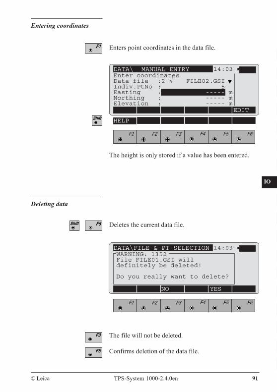
CO
IN
ID
PM
FS
SC
OC
IO
AR
RC
EG
CA
CT
BC
DF
SD
TS
IX
© Leica TPS-System 1000-2.4.0en 91
DATA\ MANUAL ENTRY 14:03Enter coordinatesData file :2 √ FILE02.GSIIndiv.PtNo : 5Easting : ----- mNorthing : ----- mElevation : ----- m
EDIT
F1 F2 F3 F4 F5 F6
HELP
The height is only stored if a value has been entered.
Entering coordinates
Enters point coordinates in the data file.
DATA\FILE & PT SELECTION 14:03
NO YES
WARNING: 1352File FILE01.GSI willdefinitely be deleted!
Do you really want to delete?
F1 F2 F3 F4 F5 F6
The file will not be deleted.
Confirms deletion of the data file.
Deletes the current data file.
Deleting data
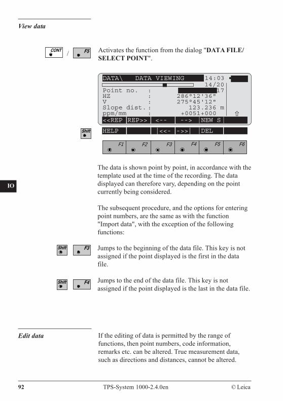
92 TPS-System 1000-2.4.0en © Leica
CO
IN
ID
PM
FS
SC
OC
IO
AR
RC
EG
CA
CT
BC
DF
SD
TS
IX
View data
Activates the function from the dialog "DATA FILE/SELECT POINT".
DATA\ DATA VIEWING 14:03
<<REP REP>> <-- --> NEW S
F1 F2 F3 F4 F5 F6
HELP |<<- ->>| DEL
The data is shown point by point, in accordance with thetemplate used at the time of the recording. The datadisplayed can therefore vary, depending on the pointcurrently being considered.
The subsequent procedure, and the options for enteringpoint numbers, are the same as with the function"Import data", with the exception of the followingfunctions:
Jumps to the beginning of the data file. This key is notassigned if the point displayed is the first in the datafile.
Jumps to the end of the data file. This key is notassigned if the point displayed is the last in the data file.
14/20Point no. : 17HZ : 286°12'36"V : 275°45'12"Slope dist. : 123.236 mppm/mm : +0051+000
/
Edit data If the editing of data is permitted by the range offunctions, then point numbers, code information,remarks etc. can be altered. True measurement data,such as directions and distances, cannot be altered.
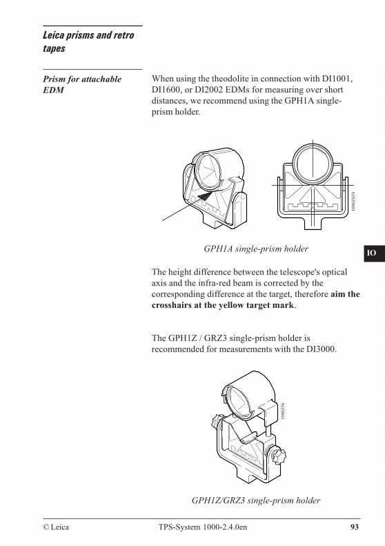
CO
IN
ID
PM
FS
SC
OC
IO
AR
RC
EG
CA
CT
BC
DF
SD
TS
IX
© Leica TPS-System 1000-2.4.0en 93
Leica prisms and retrotapes
Prism for attachableEDM
When using the theodolite in connection with DI1001,DI1600, or DI2002 EDMs for measuring over shortdistances, we recommend using the GPH1A single-prism holder.
GPH1A single-prism holder
1000
Z024
GPH1Z/GRZ3 single-prism holder
1000
Z56
The height difference between the telescope's opticalaxis and the infra-red beam is corrected by thecorresponding difference at the target, therefore aim thecrosshairs at the yellow target mark.
The GPH1Z / GRZ3 single-prism holder isrecommended for measurements with the DI3000.
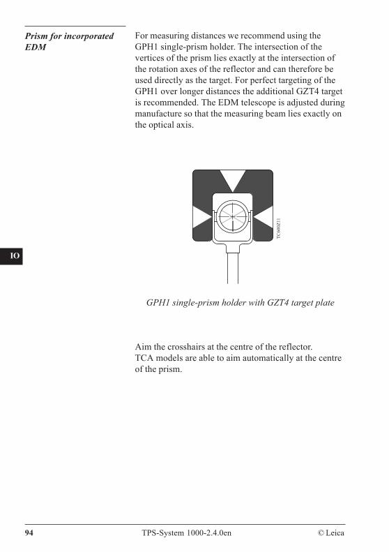
94 TPS-System 1000-2.4.0en © Leica
CO
IN
ID
PM
FS
SC
OC
IO
AR
RC
EG
CA
CT
BC
DF
SD
TS
IX
Prism for incorporatedEDM
For measuring distances we recommend using theGPH1 single-prism holder. The intersection of thevertices of the prism lies exactly at the intersection ofthe rotation axes of the reflector and can therefore beused directly as the target. For perfect targeting of theGPH1 over longer distances the additional GZT4 targetis recommended. The EDM telescope is adjusted duringmanufacture so that the measuring beam lies exactly onthe optical axis.
TC60
0Z11
GPH1 single-prism holder with GZT4 target plate
Aim the crosshairs at the centre of the reflector.TCA models are able to aim automatically at the centreof the prism.

CO
IN
ID
PM
FS
SC
OC
IO
AR
RC
EG
CA
CT
BC
DF
SD
TS
IX
© Leica TPS-System 1000-2.4.0en 95
The GRZ4 360° reflector The GRZ4 reflector is a special 360-degree prism and isavailable as an option. It allows measurements andautomatic target recognition from any direction.Since it does not always need to be turned towards theinstrument, the reflector provides additional comfort fora rodman and improved surveying efficiency.
The grouping of the 6 prisms of the 360° reflectormakes• the accuracy of horizontal measurement and• the accuracy of vertical measurementwith automatic target recognition independent of theposition of the reflector.The overall positioning accuracy of the reflector is ±5mm in distance and ±5 mm for the angle (horizontal andvertical).When the arrow on the upper rubberizedmount points towards the instrument and therefore thefront face of a prism points towards the EDM, theaccuracy is improved.The GRZ4 reflector is highly recommended fortopographic and stake-out surveys. Leica circularprisms are recommended for surveys requiring higheraccuracy than that provided by the GRZ4 prism.
1000
Z025
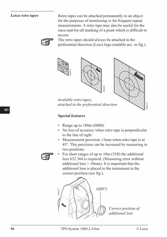
96 TPS-System 1000-2.4.0en © Leica
CO
IN
ID
PM
FS
SC
OC
IO
AR
RC
EG
CA
CT
BC
DF
SD
TS
IX
Leica retro tapes Retro tapes can be attached permanently to an objectfor the purposes of monitoring or for frequent repeatmeasurements. A retro tape may also be useful for theonce-and-for-all marking of a point which is difficult toaccess.The retro tapes should always be attached in thepreferential direction (Leica logo readable acc. to fig.).
1000
Z57
Correct position ofadditional lens
GDV3
1000
Z41
1000
Z42
1000
Z43
Available retro tapes,attached in the preferential direction.
Special features
• Range up to 180m (600ft)• No loss of accuracy when retro tape is perpendicular
to the line of sight• Measurement precision ±3mm when retro tape is at
45°. This precision can be increased by measuring intwo positions.
• For short ranges of up to 10m (33ft) the additionallens 632 364 is required. (Measuring error withoutadditional lens > 10mm). It is important that theadditional lens is placed to the instrument in thecorrect position (see fig.).
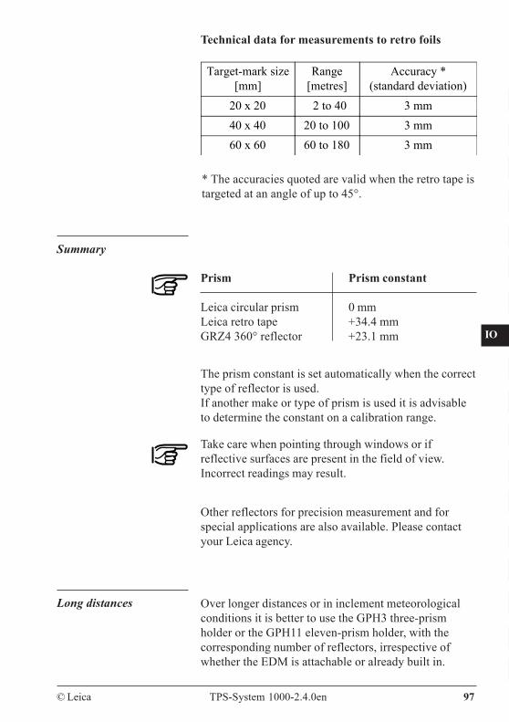
CO
IN
ID
PM
FS
SC
OC
IO
AR
RC
EG
CA
CT
BC
DF
SD
TS
IX
© Leica TPS-System 1000-2.4.0en 97
Long distances Over longer distances or in inclement meteorologicalconditions it is better to use the GPH3 three-prismholder or the GPH11 eleven-prism holder, with thecorresponding number of reflectors, irrespective ofwhether the EDM is attachable or already built in.
* The accuracies quoted are valid when the retro tape istargeted at an angle of up to 45°.
Target-mark size[mm]
Range[metres]
Accuracy *(standard deviation)
20 x 20 2 to 40 3 mm40 x 40 20 to 100 3 mm60 x 60 60 to 180 3 mm
Technical data for measurements to retro foils
Summary
Prism Prism constant
Leica circular prism 0 mmLeica retro tape +34.4 mmGRZ4 360° reflector +23.1 mm
The prism constant is set automatically when the correcttype of reflector is used.If another make or type of prism is used it is advisableto determine the constant on a calibration range.
Take care when pointing through windows or ifreflective surfaces are present in the field of view.Incorrect readings may result.
Other reflectors for precision measurement and forspecial applications are also available. Please contactyour Leica agency.

98 TPS-System 1000-2.4.0en © Leica
CO
IN
ID
PM
FS
SC
OC
IO
AR
RC
EG
CA
CT
BC
DF
SD
TS
IX
Extra
EXTRA\ EXTRA FUNCTIONS 14:03
F1 F2 F3 F4 F5 F6
1 On-line mode (GeoCOM)2 Format memory card3 Remote control mode ON/OFF
HELP
Activates the "EXTRA" function in the main menu.
The following display refers only to TCA versions. Allother versions lack the "Remote control mode".
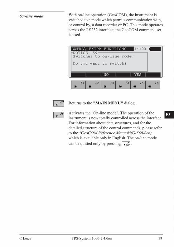
CO
IN
ID
PM
FS
SC
OC
IO
AR
RC
EG
CA
CT
BC
DF
SD
TS
IX
© Leica TPS-System 1000-2.4.0en 99
On-line mode With on-line operation (GeoCOM), the instrument isswitched to a mode which permits communication with,or control by, a data recorder or PC. This mode operatesacross the RS232 interface; the GeoCOM command setis used.
EXTRA\ EXTRA FUNCTIONS 14:03NOTICE: 59Switches to on-line mode.
Do you want to switch?
NO YES
F1 F2 F3 F4 F5 F6
Returns to the "MAIN MENU" dialog.
Activates the "On-line mode". The operation of theinstrument is now totally controlled across the interface.For information about data structures, and for thedetailed structure of the control commands, please referto the "GeoCOM Reference Manual"(G-560-0en),which is available only in English. The on-line modecan be quitted only by pressing .
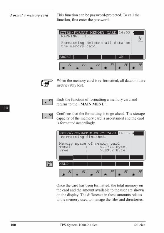
100 TPS-System 1000-2.4.0en © Leica
CO
IN
ID
PM
FS
SC
OC
IO
AR
RC
EG
CA
CT
BC
DF
SD
TS
IX
Format a memory card This function can be password-protected. To call thefunction, first enter the password.
EXTRA\FORMAT MEMORY CARD 14:03WARNING: 1151
Formatting deletes all data onthe memory card.
ABORT OK
F1 F2 F3 F4 F5 F6
MC
Ends the function of formatting a memory card andreturns to the "MAIN MENU".
Confirms that the formatting is to go ahead. The storagecapacity of the memory card is ascertained and the cardis formatted accordingly.
EXTRA\FORMAT MEMORY CARD 14:03Formatting finished.
Memory space of memory cardTotal : 523776 ByteFree : 509952 Byte
F1 F2 F3 F4 F5 F6
HELP
Once the card has been formatted, the total memory onthe card and the amount available to the user are shownon the display. The difference in these amounts relatesto the memory used to manage the files and directories.
When the memory card is re-formatted, all data on it areirretrievably lost.
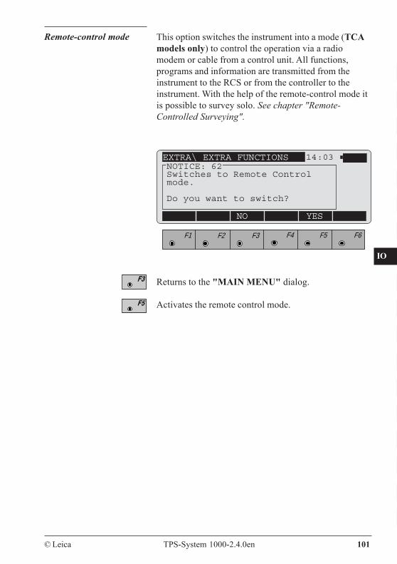
CO
IN
ID
PM
FS
SC
OC
IO
AR
RC
EG
CA
CT
BC
DF
SD
TS
IX
© Leica TPS-System 1000-2.4.0en 101
This option switches the instrument into a mode (TCAmodels only) to control the operation via a radiomodem or cable from a control unit. All functions,programs and information are transmitted from theinstrument to the RCS or from the controller to theinstrument. With the help of the remote-control mode itis possible to survey solo. See chapter "Remote-Controlled Surveying".
Remote-control mode
Returns to the "MAIN MENU" dialog.
Activates the remote control mode.
EXTRA\ EXTRA FUNCTIONS 14:03
NO YES
F1 F2 F3 F4 F5 F6
NOTICE: 62Switches to Remote Controlmode.
Do you want to switch?
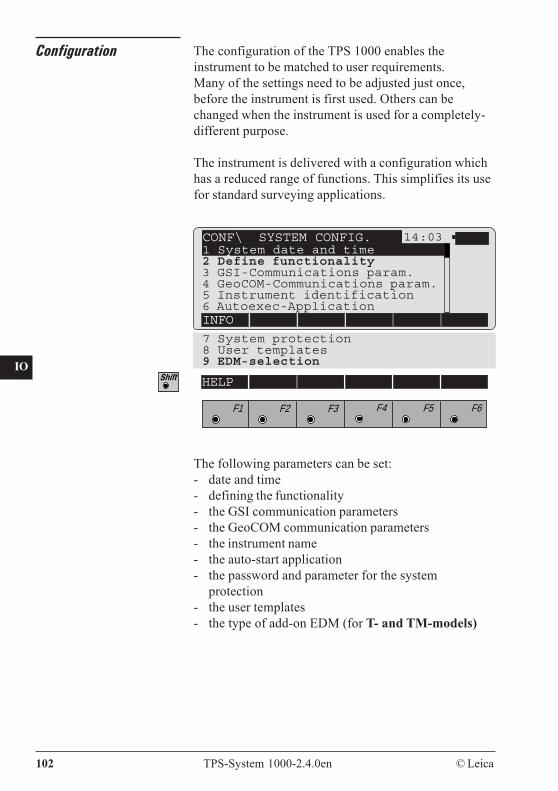
102 TPS-System 1000-2.4.0en © Leica
CO
IN
ID
PM
FS
SC
OC
IO
AR
RC
EG
CA
CT
BC
DF
SD
TS
IX
Configuration The configuration of the TPS 1000 enables theinstrument to be matched to user requirements.Many of the settings need to be adjusted just once,before the instrument is first used. Others can bechanged when the instrument is used for a completely-different purpose.
The instrument is delivered with a configuration whichhas a reduced range of functions. This simplifies its usefor standard surveying applications.
CONF\ SYSTEM CONFIG. 14:031 System date and time2 Define functionality3 GSI-Communications param.4 GeoCOM-Communications param.5 Instrument identification6 Autoexec-ApplicationINFO
7 System protection8 User templates9 EDM-selection
F1 F2 F3 F4 F5 F6
HELP
The following parameters can be set:- date and time- defining the functionality- the GSI communication parameters- the GeoCOM communication parameters- the instrument name- the auto-start application- the password and parameter for the system
protection- the user templates- the type of add-on EDM (for T- and TM-models)
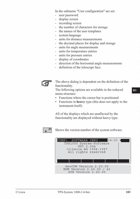
CO
IN
ID
PM
FS
SC
OC
IO
AR
RC
EG
CA
CT
BC
DF
SD
TS
IX
© Leica TPS-System 1000-2.4.0en 103
In the submenu "User configuration" are set:- user password- display screen- recording screen- the number of characters for storage- the names of the user templates- system language- units for distance measurements- the decimal places for display and storage- units for angle measurements- units for temperature entries- units for pressure entries- display of coordinates- direction of the horizontal angle measurements- definition of the telescope face.
The above dialog is dependent on the definition of thefunctionality.The following options are available in the reducedmenu structure:• Functions where the cursor bar is positioned• Functions in heavy type (this does not apply to the
instrument itself).
All of the displays which are unaffected by thefunctionality are displayed without heavy type.
Shows the version number of the system software.
CONF\ SOFTWARE INFO 14:03TPS1000 System-Software
GSI 2.20a(c)Leica AG 1994-1997All rights reserved
GeoCOM Version 2.20.00EDM Version 2.20.00 / 41
ATR Version 2.20.00
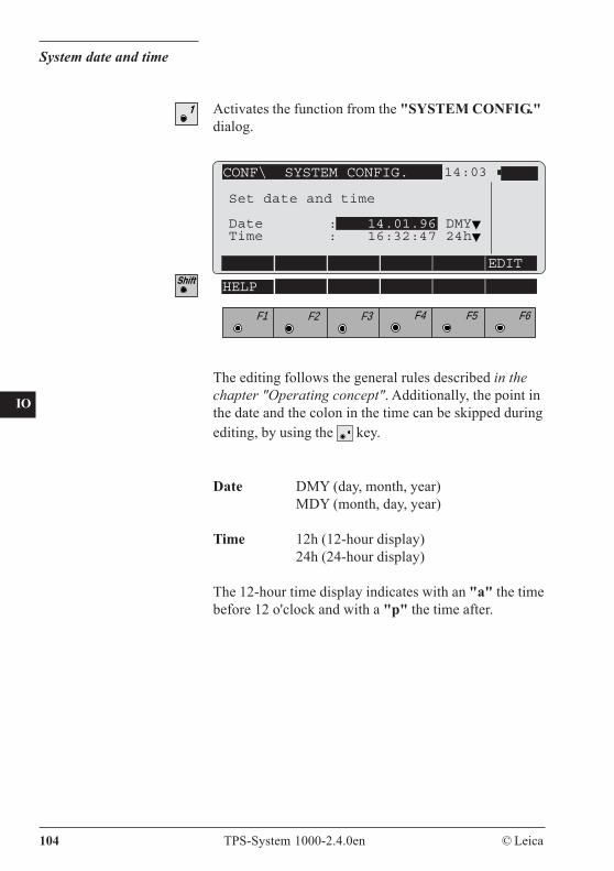
104 TPS-System 1000-2.4.0en © Leica
CO
IN
ID
PM
FS
SC
OC
IO
AR
RC
EG
CA
CT
BC
DF
SD
TS
IX
System date and time
Activates the function from the "SYSTEM CONFIG."dialog.
CONF\ SYSTEM CONFIG. 14:03
EDIT
F1 F2 F3 F4 F5 F6
HELP
Set date and time
Date : 14.01.96 DMYTime : 16:32:47 24h
The editing follows the general rules described in thechapter "Operating concept". Additionally, the point inthe date and the colon in the time can be skipped duringediting, by using the key.
Date DMY (day, month, year)MDY (month, day, year)
Time 12h (12-hour display)24h (24-hour display)
The 12-hour time display indicates with an "a" the timebefore 12 o'clock and with a "p" the time after.

CO
IN
ID
PM
FS
SC
OC
IO
AR
RC
EG
CA
CT
BC
DF
SD
TS
IX
© Leica TPS-System 1000-2.4.0en 105
Activates the function from the "SYSTEM CONFIG."dialog.
The range of functions available in the TPS1000 can bedefined. The instrument is delivered with aconfiguration which has a reduced range of functions.
Define functionality
Show all menus and keys
YES All functions can be activated.
NO The range of functions which can becalled is reduced.Functions which are always available areindicated in heavy type in the dialogs.
Show full ppm definition
YES Meteorological and geometrical correctionscan be entered and a scale factor can be takeninto account. For height calculations, arefraction coefficient which differs from thestandard value can be entered.
CONF\ FUNCTIONALITY 14:03
DEFLT YES
F1 F2 F3 F4 F5 F6
HELP FULL
Select functionality
Show all menus and keys : NOShow full ppm definition : NOEnable user configurat. : NOAllow data editing : NO
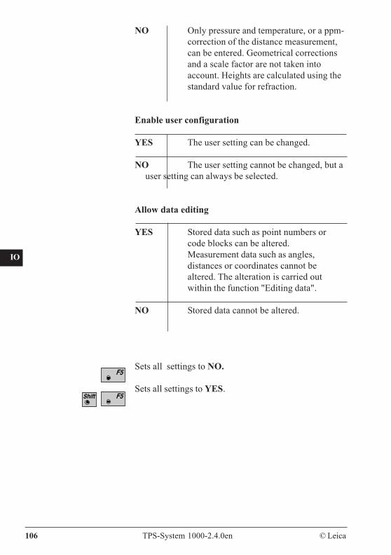
106 TPS-System 1000-2.4.0en © Leica
CO
IN
ID
PM
FS
SC
OC
IO
AR
RC
EG
CA
CT
BC
DF
SD
TS
IX
NO Only pressure and temperature, or a ppm-correction of the distance measurement,can be entered. Geometrical correctionsand a scale factor are not taken intoaccount. Heights are calculated using thestandard value for refraction.
Enable user configuration
YES The user setting can be changed.
NO The user setting cannot be changed, but auser setting can always be selected.
Allow data editing
YES Stored data such as point numbers orcode blocks can be altered.Measurement data such as angles,distances or coordinates cannot bealtered. The alteration is carried outwithin the function "Editing data".
NO Stored data cannot be altered.
Sets all settings to NO.
Sets all settings to YES.
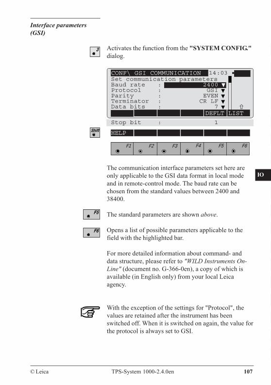
CO
IN
ID
PM
FS
SC
OC
IO
AR
RC
EG
CA
CT
BC
DF
SD
TS
IX
© Leica TPS-System 1000-2.4.0en 107
Interface parameters(GSI)
CONF\ GSI COMMUNICATION 14:03
DEFLT LIST
Stop bit : 1
F1 F2 F3 F4 F5 F6
HELP
The communication interface parameters set here areonly applicable to the GSI data format in local modeand in remote-control mode. The baud rate can bechosen from the standard values between 2400 and38400.
The standard parameters are shown above.
Opens a list of possible parameters applicable to thefield with the highlighted bar.
For more detailed information about command- anddata structure, please refer to "WILD Instruments On-Line" (document no. G-366-0en), a copy of which isavailable (in English only) from your local Leicaagency.
With the exception of the settings for "Protocol", thevalues are retained after the instrument has beenswitched off. When it is switched on again, the value forthe protocol is always set to GSI.
Activates the function from the "SYSTEM CONFIG."dialog.
Set communication parametersBaud rate : 2400Protocol : GSIParity : EVENTerminator : CR LFData bits : 7
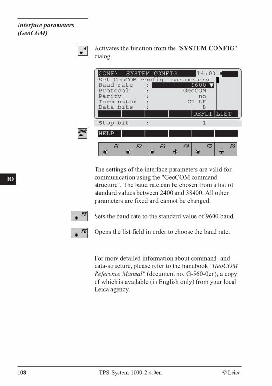
108 TPS-System 1000-2.4.0en © Leica
CO
IN
ID
PM
FS
SC
OC
IO
AR
RC
EG
CA
CT
BC
DF
SD
TS
IX
Interface parameters(GeoCOM)
CONF\ SYSTEM CONFIG. 14:03
DEFLT LIST
Stop bit : 1
F1 F2 F3 F4 F5 F6
HELP
Set GeoCOM-config. parametersBaud rate : 9600Protocol : GeoCOMParity : noTerminator : CR LFData bits : 8
The settings of the interface parameters are valid forcommunication using the "GeoCOM commandstructure". The baud rate can be chosen from a list ofstandard values between 2400 and 38400. All otherparameters are fixed and cannot be changed.
Sets the baud rate to the standard value of 9600 baud.
Opens the list field in order to choose the baud rate.
Activates the function from the "SYSTEM CONFIG"dialog.
For more detailed information about command- anddata-structure, please refer to the handbook "GeoCOMReference Manual" (document no. G-560-0en), a copyof which is available (in English only) from your localLeica agency.
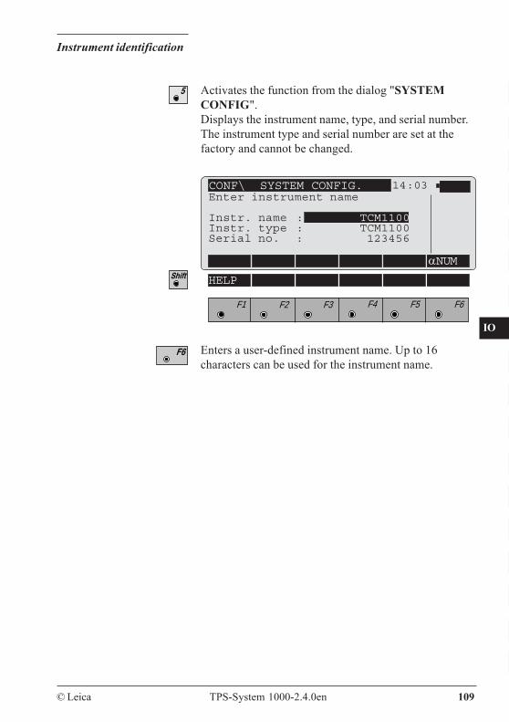
CO
IN
ID
PM
FS
SC
OC
IO
AR
RC
EG
CA
CT
BC
DF
SD
TS
IX
© Leica TPS-System 1000-2.4.0en 109
Instrument identification
Activates the function from the dialog "SYSTEMCONFIG".Displays the instrument name, type, and serial number.The instrument type and serial number are set at thefactory and cannot be changed.
CONF\ SYSTEM CONFIG. 14:03
αNUM
Enter instrument name
Instr. name : TCM1100Instr. type : TCM1100Serial no. : 123456
F1 F2 F3 F4 F5 F6
HELP
Enters a user-defined instrument name. Up to 16characters can be used for the instrument name.
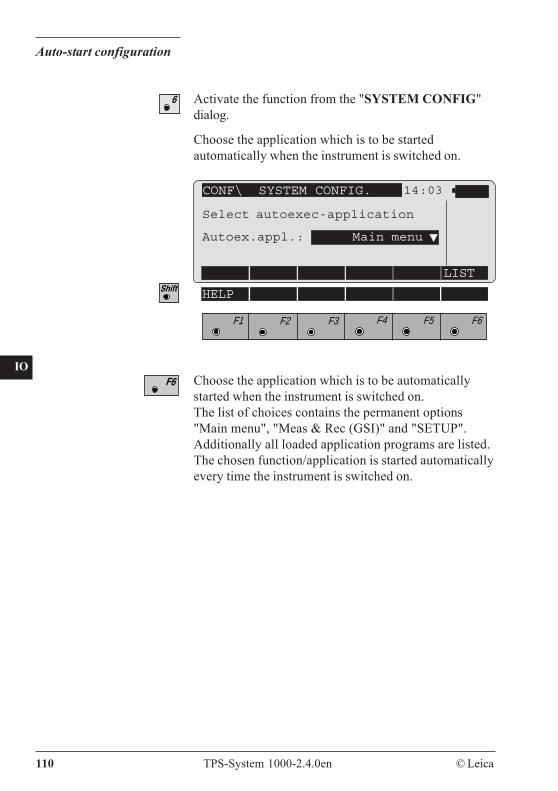
110 TPS-System 1000-2.4.0en © Leica
CO
IN
ID
PM
FS
SC
OC
IO
AR
RC
EG
CA
CT
BC
DF
SD
TS
IX
Auto-start configuration
CONF\ SYSTEM CONFIG. 14:03
LIST
F1 F2 F3 F4 F5 F6
HELP
Select autoexec-application
Autoex.appl.: Main menu
Choose the application which is to be automaticallystarted when the instrument is switched on.The list of choices contains the permanent options"Main menu", "Meas & Rec (GSI)" and "SETUP".Additionally all loaded application programs are listed.The chosen function/application is started automaticallyevery time the instrument is switched on.
Choose the application which is to be startedautomatically when the instrument is switched on.
Activate the function from the "SYSTEM CONFIG"dialog.
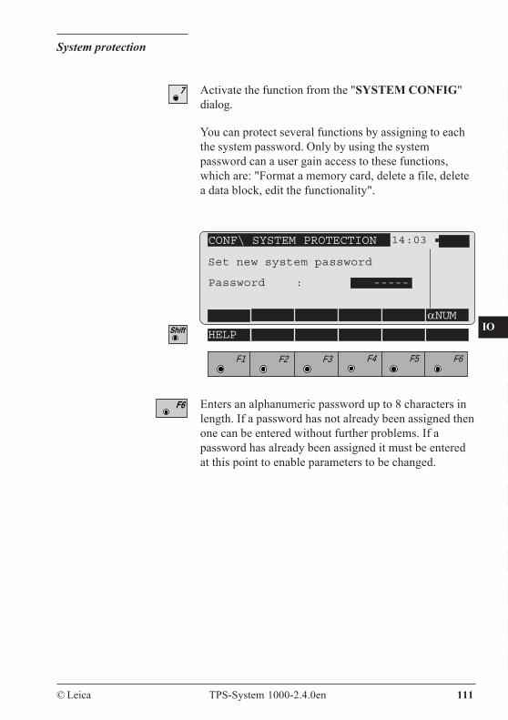
CO
IN
ID
PM
FS
SC
OC
IO
AR
RC
EG
CA
CT
BC
DF
SD
TS
IX
© Leica TPS-System 1000-2.4.0en 111
System protection
Activate the function from the "SYSTEM CONFIG"dialog.
You can protect several functions by assigning to eachthe system password. Only by using the systempassword can a user gain access to these functions,which are: "Format a memory card, delete a file, deletea data block, edit the functionality".
CONF\ SYSTEM PROTECTION 14:03
αNUM
F1 F2 F3 F4 F5 F6
HELP
Set new system password
Password : -----
Enters an alphanumeric password up to 8 characters inlength. If a password has not already been assigned thenone can be entered without further problems. If apassword has already been assigned it must be enteredat this point to enable parameters to be changed.
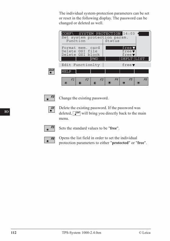
112 TPS-System 1000-2.4.0en © Leica
CO
IN
ID
PM
FS
SC
OC
IO
AR
RC
EG
CA
CT
BC
DF
SD
TS
IX
The individual system-protection parameters can be setor reset in the following display. The password can bechanged or deleted as well.
CONF\ SYSTEM PROTECTION 14:03
PWD DEFLT LIST
Edit Functionlty free
F1 F2 F3 F4 F5 F6
HELP
Set system protection param. Function Status
Format mem. card freeDelete GSI file freeDelete GSI block free
Change the existing password.
Delete the existing password. If the password wasdeleted, will bring you directly back to the mainmenu.
Sets the standard values to be "free".
Opens the list field in order to set the individualprotection parameters to either "protected" or "free".
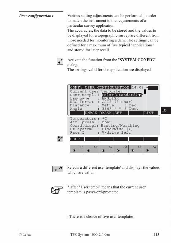
CO
IN
ID
PM
FS
SC
OC
IO
AR
RC
EG
CA
CT
BC
DF
SD
TS
IX
© Leica TPS-System 1000-2.4.0en 113
User configurations Various setting adjustments can be performed in orderto match the instrument to the requirements of aparticular survey application.The accuracies, the data to be stored and the values tobe displayed for a topographic survey are different fromthose needed for monitoring a dam. The settings can bedefined for a maximum of five typical "applications"and stored for later recall.
Activate the function from the "SYSTEM CONFIG"dialog.The settings valid for the application are displayed.
Temperature : °CAtm. press. : mbarCoord.displ: Easting/NorthingHz-system : Clockwise (+)Face I : V-drive left
CONF\ USER CONFIGURATION 14:03
RMASK DMASK SET LIST
F1 F2 F3 F4 F5 F6
HELP
Selects a different user template1 and displays the valueswhich are valid.
* after "User templ" means that the current usertemplate is password-protected.
1 There is a choice of five user templates.
HELP
Current user template:User templ. : Polar(Standard) *Language : ENGLISHREC Format : GSI8 (8 char)Distance : Metre 3 Dec.Angle : 360° ' " 3 Dec.
8
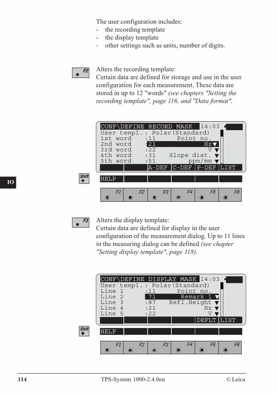
114 TPS-System 1000-2.4.0en © Leica
CO
IN
ID
PM
FS
SC
OC
IO
AR
RC
EG
CA
CT
BC
DF
SD
TS
IX
The user configuration includes:- the recording template- the display template- other settings such as units, number of digits.
Alters the recording template:Certain data are defined for storage and use in the userconfiguration for each measurement. These data arestored in up to 12 "words" (see chapters "Setting therecording template", page 116, and "Data format".
CONF\DEFINE RECORD MASK 14:03
A-DEF C-DEF P-DEF LIST
F1 F2 F3 F4 F5 F6
HELP
CONF\DEFINE DISPLAY MASK 14:03
DEFLT LIST
HELP
F1 F2 F3 F4 F5 F6
User templ. : Polar(Standard)Line 1 :11 Point no.Line 2 :71 Remark 1Line 3 :87 Refl.HeightLine 4 :21 HzLine 5 :22 V
User templ. : Polar(Standard)1st word :11 Point no.2nd word :21 Hz 1
3rd word :22 V4th word :31 Slope dist.5th word :51 ppm/mm
Alters the display template:Certain data are defined for display in the userconfiguration of the measurement dialog. Up to 11 linesin the measuring dialog can be defined (see chapter"Setting display template", page 118).
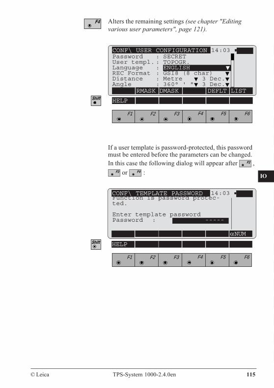
CO
IN
ID
PM
FS
SC
OC
IO
AR
RC
EG
CA
CT
BC
DF
SD
TS
IX
© Leica TPS-System 1000-2.4.0en 115
Alters the remaining settings (see chapter "Editingvarious user parameters", page 121).
CONF\ USER CONFIGURATION 14:03
RMASK DMASK DEFLT LIST
F1 F2 F3 F4 F5 F6
HELP
Password : SECRETUser templ. : TOPOGR.Language : ENGLISHREC Format : GSI8 (8 char)Distance : Metre 3 Dec.Angle : 360° ' " 3 Dec.
CONF\ TEMPLATE PASSWORD 14:03
αNUM
F1 F2 F3 F4 F5 F6
HELP
If a user template is password-protected, this passwordmust be entered before the parameters can be changed.In this case the following dialog will appear after ,
or :
Function is password protec-ted.
Enter template passwordPassword : -----
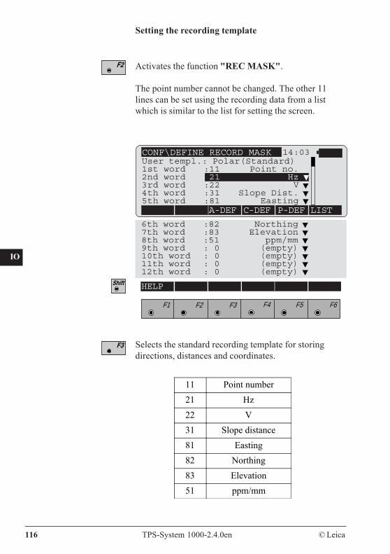
116 TPS-System 1000-2.4.0en © Leica
CO
IN
ID
PM
FS
SC
OC
IO
AR
RC
EG
CA
CT
BC
DF
SD
TS
IX
Activates the function "REC MASK".
The point number cannot be changed. The other 11lines can be set using the recording data from a listwhich is similar to the list for setting the screen.
6th word :82 Northing7th word :83 Elevation8th word :51 ppm/mm9th word : 0 (empty)10th word : 0 (empty)11th word : 0 (empty)12th word : 0 (empty)
Setting the recording template
CONF\DEFINE RECORD MASK 14:03
A-DEF C-DEF P-DEF LIST
User templ.: Polar(Standard)1st word :11 Point no.2nd word :21 Hz3rd word :22 V4th word :31 Slope Dist.5th word :81 Easting
F1 F2 F3 F4 F5 F6
HELP
Selects the standard recording template for storingdirections, distances and coordinates.
11 Point number21 Hz22 V31 Slope distance81 Easting82 Northing83 Elevation51 ppm/mm
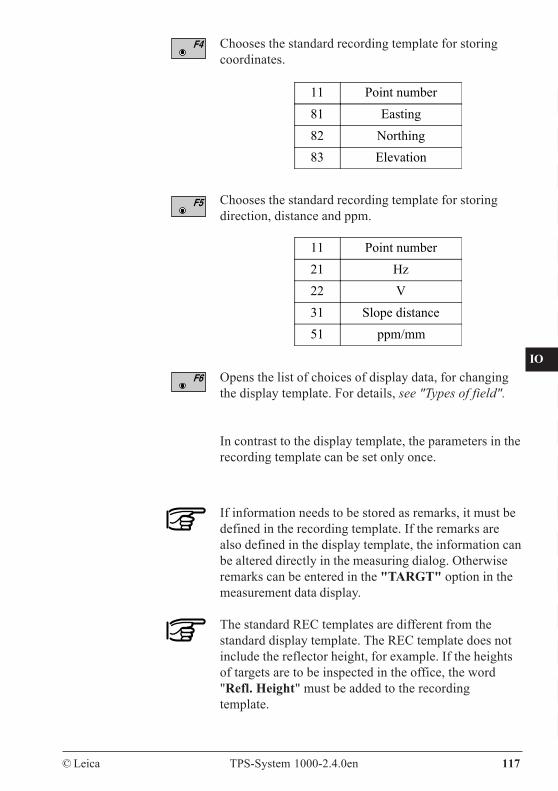
CO
IN
ID
PM
FS
SC
OC
IO
AR
RC
EG
CA
CT
BC
DF
SD
TS
IX
© Leica TPS-System 1000-2.4.0en 117
Chooses the standard recording template for storingcoordinates.
Chooses the standard recording template for storingdirection, distance and ppm.
Opens the list of choices of display data, for changingthe display template. For details, see "Types of field".
In contrast to the display template, the parameters in therecording template can be set only once.
11 Point number81 Easting82 Northing83 Elevation
11 Point number21 Hz22 V31 Slope distance51 ppm/mm
If information needs to be stored as remarks, it must bedefined in the recording template. If the remarks arealso defined in the display template, the information canbe altered directly in the measuring dialog. Otherwiseremarks can be entered in the "TARGT" option in themeasurement data display.
The standard REC templates are different from thestandard display template. The REC template does notinclude the reflector height, for example. If the heightsof targets are to be inspected in the office, the word"Refl. Height" must be added to the recordingtemplate.
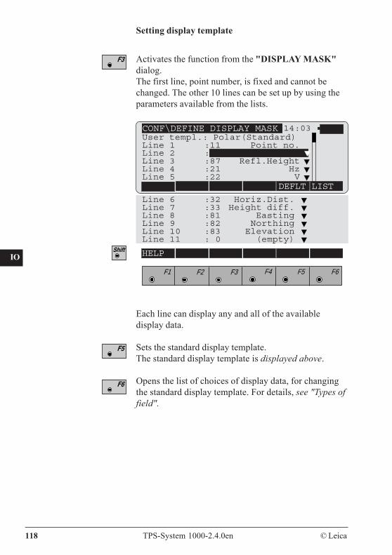
118 TPS-System 1000-2.4.0en © Leica
CO
IN
ID
PM
FS
SC
OC
IO
AR
RC
EG
CA
CT
BC
DF
SD
TS
IX
Setting display template
Activates the function from the "DISPLAY MASK"dialog.The first line, point number, is fixed and cannot bechanged. The other 10 lines can be set up by using theparameters available from the lists.
CONF\DEFINE DISPLAY MASK 14:03
DEFLT LIST
Line 6 :32 Horiz.Dist.Line 7 :33 Height diff.Line 8 :81 EastingLine 9 :82 NorthingLine 10 :83 ElevationLine 11 : 0 (empty)
User templ.: Polar(Standard)Line 1 :11 Point no.Line 2 :71 Remark 1Line 3 :87 Refl.HeightLine 4 :21 HzLine 5 :22 V
F1 F2 F3 F4 F5 F6
HELP
Each line can display any and all of the availabledisplay data.
Sets the standard display template.The standard display template is displayed above.
Opens the list of choices of display data, for changingthe standard display template. For details, see "Types offield".
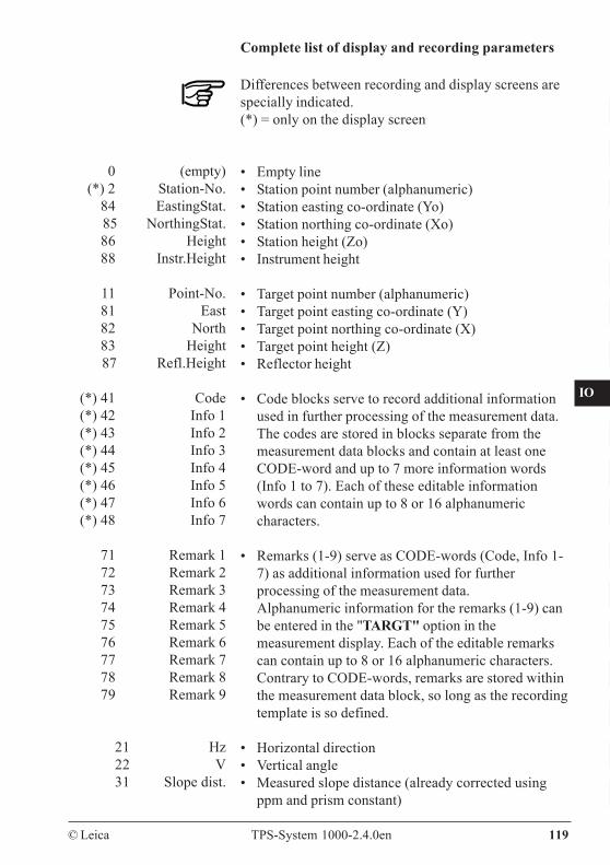
CO
IN
ID
PM
FS
SC
OC
IO
AR
RC
EG
CA
CT
BC
DF
SD
TS
IX
© Leica TPS-System 1000-2.4.0en 119
Complete list of display and recording parameters
Differences between recording and display screens arespecially indicated.(*) = only on the display screen
• Empty line• Station point number (alphanumeric)• Station easting co-ordinate (Yo)• Station northing co-ordinate (Xo)• Station height (Zo)• Instrument height
• Target point number (alphanumeric)• Target point easting co-ordinate (Y)• Target point northing co-ordinate (X)• Target point height (Z)• Reflector height
• Code blocks serve to record additional informationused in further processing of the measurement data.The codes are stored in blocks separate from themeasurement data blocks and contain at least oneCODE-word and up to 7 more information words(Info 1 to 7). Each of these editable informationwords can contain up to 8 or 16 alphanumericcharacters.
• Remarks (1-9) serve as CODE-words (Code, Info 1-7) as additional information used for furtherprocessing of the measurement data.Alphanumeric information for the remarks (1-9) canbe entered in the "TARGT" option in themeasurement display. Each of the editable remarkscan contain up to 8 or 16 alphanumeric characters.Contrary to CODE-words, remarks are stored withinthe measurement data block, so long as the recordingtemplate is so defined.
• Horizontal direction• Vertical angle• Measured slope distance (already corrected using
ppm and prism constant)
0 (empty)(*) 2 Station-No.
84 EastingStat.85 NorthingStat.86 Height88 Instr.Height
11 Point-No.81 East82 North83 Height87 Refl.Height
(*) 41 Code(*) 42 Info 1(*) 43 Info 2(*) 44 Info 3(*) 45 Info 4(*) 46 Info 5(*) 47 Info 6(*) 48 Info 7
71 Remark 172 Remark 273 Remark 374 Remark 475 Remark 576 Remark 677 Remark 778 Remark 879 Remark 9
21 Hz22 V31 Slope dist.
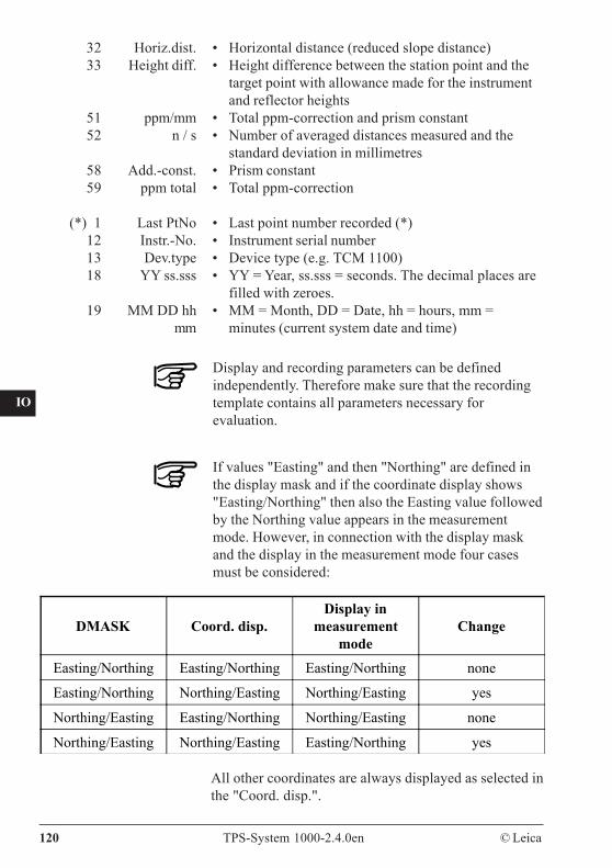
120 TPS-System 1000-2.4.0en © Leica
CO
IN
ID
PM
FS
SC
OC
IO
AR
RC
EG
CA
CT
BC
DF
SD
TS
IX
• Horizontal distance (reduced slope distance)• Height difference between the station point and the
target point with allowance made for the instrumentand reflector heights
• Total ppm-correction and prism constant• Number of averaged distances measured and the
standard deviation in millimetres• Prism constant• Total ppm-correction
• Last point number recorded (*)• Instrument serial number• Device type (e.g. TCM 1100)• YY = Year, ss.sss = seconds. The decimal places are
filled with zeroes.• MM = Month, DD = Date, hh = hours, mm =
minutes (current system date and time)
32 Horiz.dist.33 Height diff.
51 ppm/mm52 n / s
58 Add.-const.59 ppm total
(*) 1 Last PtNo12 Instr.-No.13 Dev.type18 YY ss.sss
19 MM DD hhmm
All other coordinates are always displayed as selected inthe "Coord. disp.".
Display and recording parameters can be definedindependently. Therefore make sure that the recordingtemplate contains all parameters necessary forevaluation.
If values "Easting" and then "Northing" are defined inthe display mask and if the coordinate display shows"Easting/Northing" then also the Easting value followedby the Northing value appears in the measurementmode. However, in connection with the display maskand the display in the measurement mode four casesmust be considered:
DMASK Coord. disp.Display in
measurementmode
Change
Easting/Northing Easting/Northing Easting/Northing none
Easting/Northing Northing/Easting Northing/Easting yes
Northing/Easting Easting/Northing Northing/Easting none
Northing/Easting Northing/Easting Easting/Northing yes
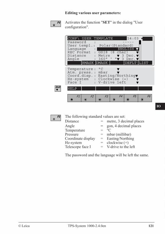
CO
IN
ID
PM
FS
SC
OC
IO
AR
RC
EG
CA
CT
BC
DF
SD
TS
IX
© Leica TPS-System 1000-2.4.0en 121
Editing various user parameters:
Activates the function "SET" in the dialog "Userconfiguration".
Temperature : °C Atm. press. : mbar Coord.disp. : Easting/NorthingHz-system : Clockwise (+)Face I : V-drive left
F1 F2 F3 F4 F5 F6
HELP
CONF\ USER TEMPLATE 14:03
RMASK DMASK DEFLT LIST
Password : -----User templ.: Polar(Standard)Language : ENGLISHREC Format : GSI8 (8 char)Distance : Metre 3 Dec.Angle : 360° ' " 3 Dec.
The following standard values are set:Distance = metre, 3 decimal placesAngle = gon, 4 decimal placesTemperature = °CPressure = mbar (millibar)Coordinate display = Easting/NorthingHz-system = clockwise (+)Telescope face I = V-drive to the left
The password and the language will be left the same.
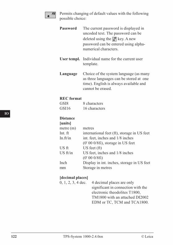
122 TPS-System 1000-2.4.0en © Leica
CO
IN
ID
PM
FS
SC
OC
IO
AR
RC
EG
CA
CT
BC
DF
SD
TS
IX
Permits changing of default values with the followingpossible choice:
Password The current password is displayed inuncoded text. The password can bedeleted using the key. A newpassword can be entered using alpha-numerical characters.
User templ. Individual name for the current usertemplate.
Language Choice of the system language (as manyas three languages can be stored at onetime). English is always available andcannot be erased.
REC formatGSI8 8 charactersGSI16 16 characters
Distance[units]metre (m) metresInt. ft international feet (ft), storage in US feetIn.ft/in int. feet, inches and 1/8 inches
(0' 00 0/8fi), storage in US feetUS ft US feet (ft)US ft/in US feet, inches and 1/8 inches
(0' 00 0/8fi)Inch Display in int. inches, storage in US feetmm Storage in metres
[decimal places]0, 1, 2, 3, 4 dec. 4 decimal places are only
significant in connection with theelectronic theodolites T1800,TM1800 with an attached DI2002EDM or TC, TCM and TCA1800.
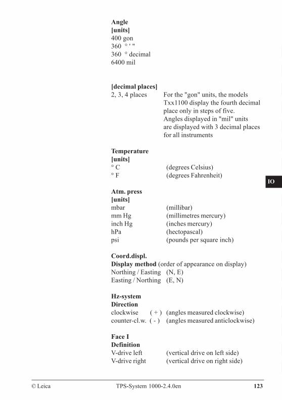
CO
IN
ID
PM
FS
SC
OC
IO
AR
RC
EG
CA
CT
BC
DF
SD
TS
IX
© Leica TPS-System 1000-2.4.0en 123
Angle[units]400 gon360 ° ' "360 ° decimal6400 mil
[decimal places]2, 3, 4 places For the "gon" units, the models
Txx1100 display the fourth decimalplace only in steps of five.Angles displayed in "mil" unitsare displayed with 3 decimal placesfor all instruments
Temperature[units]° C (degrees Celsius)° F (degrees Fahrenheit)
Atm. press[units]mbar (millibar)mm Hg (millimetres mercury)inch Hg (inches mercury)hPa (hectopascal)psi (pounds per square inch)
Coord.displ.Display method (order of appearance on display)Northing / Easting (N, E)Easting / Northing (E, N)
Hz-systemDirectionclockwise ( + ) (angles measured clockwise)counter-cl.w. ( - ) (angles measured anticlockwise)
Face IDefinitionV-drive left (vertical drive on left side)V-drive right (vertical drive on right side)
124 TPS-System 1000-2.4.0en © Leica
CO
IN
ID
PM
FS
SC
OC
IO
AR
RC
EG
CA
CT
BC
DF
SD
TS
IX
Functions of the fixedkeys
Code information Code blocks are used to record additional informationfor subsequent processing of the measurement data.They are recorded in separate blocks and consist of atleast the CODE number, along with up to 7 furtherinformation blocks (Info 1 to 7). Each of these editableinformation words contains up to 8 (or 16)alphanumeric characters.Information words which include "-----" are not stored.In general, the code function can be called whenever ameasurement or another data set in the measurement filecan be stored. The code function, together with themeasuring mode, is available in most of the loadableapplications.
calls the standard coding (Code, Info 1 to 7), if nouser-defined codes are present.
The user can use a Leica software package (codedeveloper) on a PC to program personal "User codes".These "code-functions" can contain lists of codes or, forexample, a complete process in which entries,recordings and displays are defined. On selecting a codeit is possible to record it at once.
In order for the instrument to recognize and accessthese programmed code functions, they must be storedon a memory card under the "GSI" directory in the"CODE.HEX" file.
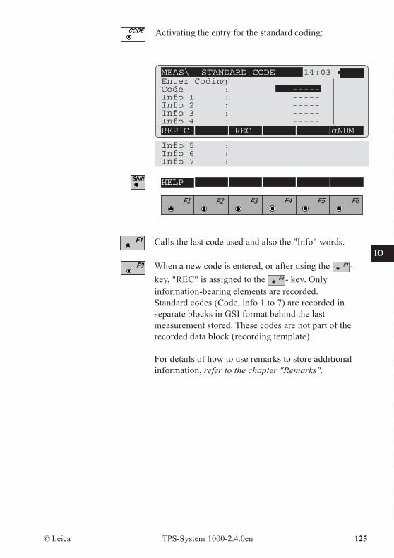
CO
IN
ID
PM
FS
SC
OC
IO
AR
RC
EG
CA
CT
BC
DF
SD
TS
IX
© Leica TPS-System 1000-2.4.0en 125
MEAS\ STANDARD CODE 14:03
REP C REC αNUM
Info 5 :Info 6 :Info 7 :
F1 F2 F3 F4 F5 F6
HELP
Enter CodingCode : -----Info 1 : -----Info 2 : -----Info 3 : -----Info 4 : -----
Activating the entry for the standard coding:
Calls the last code used and also the "Info" words.
When a new code is entered, or after using the -key, "REC" is assigned to the - key. Onlyinformation-bearing elements are recorded.Standard codes (Code, info 1 to 7) are recorded inseparate blocks in GSI format behind the lastmeasurement stored. These codes are not part of therecorded data block (recording template).
For details of how to use remarks to store additionalinformation, refer to the chapter "Remarks".
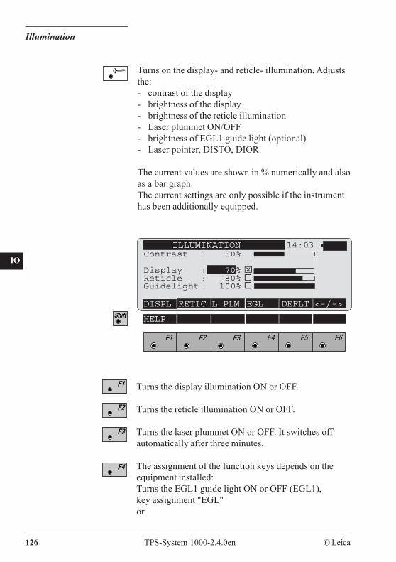
126 TPS-System 1000-2.4.0en © Leica
CO
IN
ID
PM
FS
SC
OC
IO
AR
RC
EG
CA
CT
BC
DF
SD
TS
IX
Illumination
Turns on the display- and reticle- illumination. Adjuststhe:- contrast of the display- brightness of the display- brightness of the reticle illumination- Laser plummet ON/OFF- brightness of EGL1 guide light (optional)- Laser pointer, DISTO, DIOR.
The current values are shown in % numerically and alsoas a bar graph.The current settings are only possible if the instrumenthas been additionally equipped.
ILLUMINATION 14:03Contrast : 50%
Display : 70% ⌧Reticle : 80%Guidelight : 100%
DISPL RETIC L_PLM EGL DEFLT <-/->
F1 F2 F3 F4 F5 F6
HELP
Turns the display illumination ON or OFF.
Turns the reticle illumination ON or OFF.
Turns the laser plummet ON or OFF. It switches offautomatically after three minutes.
The assignment of the function keys depends on theequipment installed:Turns the EGL1 guide light ON or OFF (EGL1),key assignment "EGL"or
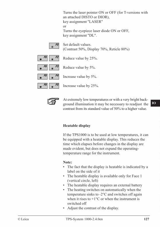
CO
IN
ID
PM
FS
SC
OC
IO
AR
RC
EG
CA
CT
BC
DF
SD
TS
IX
© Leica TPS-System 1000-2.4.0en 127
Turns the laser pointer ON or OFF (for T-versions withan attached DISTO or DIOR),key assignment "LASER"orTurns the eyepiece laser diode ON or OFF,key assignment "DL".
Set default values.(Contrast 50%, Display 70%, Reticle 80%)
Reduce value by 25%.
Reduce value by 5%.
Increase value by 5%.
Increase value by 25%.
At extremely low temperatures or with a very bright back-ground illumination it may be necessary to readjust thecontrast from its standard value of 50% to a higher value.
Heatable display
If the TPS1000 is to be used at low temperatures, it canbe equipped with a heatable display. This reduces thetime which elapses before changes in the display aremade evident, but does not expand the operating-temperature range for the instrument.
Note:• The fact that the display is heatable is indicated by a
label on the side of it• The heatable display is available only for Face 1
(vertical circle, left)• The heatable display requires an external battery• The heating switches on automatically when the
temperature sinks to -2°C and switches off againwhen it rises to +1°C or when the instrument isswitched off
• Adjust the contrast of the display.
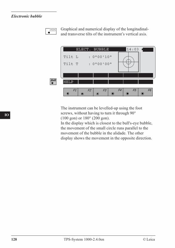
128 TPS-System 1000-2.4.0en © Leica
CO
IN
ID
PM
FS
SC
OC
IO
AR
RC
EG
CA
CT
BC
DF
SD
TS
IX
Electronic bubble
ELECT. BUBBLE 14:03
Tilt L : 0°00'10"
Tilt T : 0°00'00"
F1 F2 F3 F4 F5 F6
HELP
The instrument can be levelled-up using the footscrews, without having to turn it through 90°(100 gon) or 180° (200 gon).In the display which is closest to the bull's-eye bubble,the movement of the small circle runs parallel to themovement of the bubble in the alidade. The otherdisplay shows the movement in the opposite direction.
Graphical and numerical display of the longitudinal-and transverse tilts of the instrument’s vertical axis.
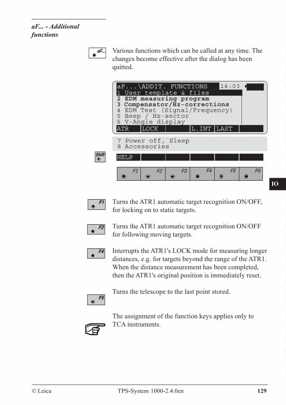
CO
IN
ID
PM
FS
SC
OC
IO
AR
RC
EG
CA
CT
BC
DF
SD
TS
IX
© Leica TPS-System 1000-2.4.0en 129
aF... - Additionalfunctions
aF...\ADDIT. FUNCTIONS 14:031 User template & files2 EDM measuring program3 Compensator/Hz-corrections4 EDM Test (Signal/Frequency)5 Beep / Hz-sector6 V-Angle displayATR LOCK L.INT LAST
aF... Various functions which can be called at any time. Thechanges become effective after the dialog has beenquitted.
7 Power off, Sleep8 Accessories
F1 F2 F3 F4 F5 F6
HELP
Turns the ATR1 automatic target recognition ON/OFF,for locking on to static targets.
Turns the ATR1 automatic target recognition ON/OFFfor following moving targets.
Interrupts the ATR1's LOCK mode for measuring longerdistances, e.g. for targets beyond the range of the ATR1.When the distance measurement has been completed,then the ATR1's original position is immediately reset.
Turns the telescope to the last point stored.
The assignment of the function keys applies only toTCA instruments.
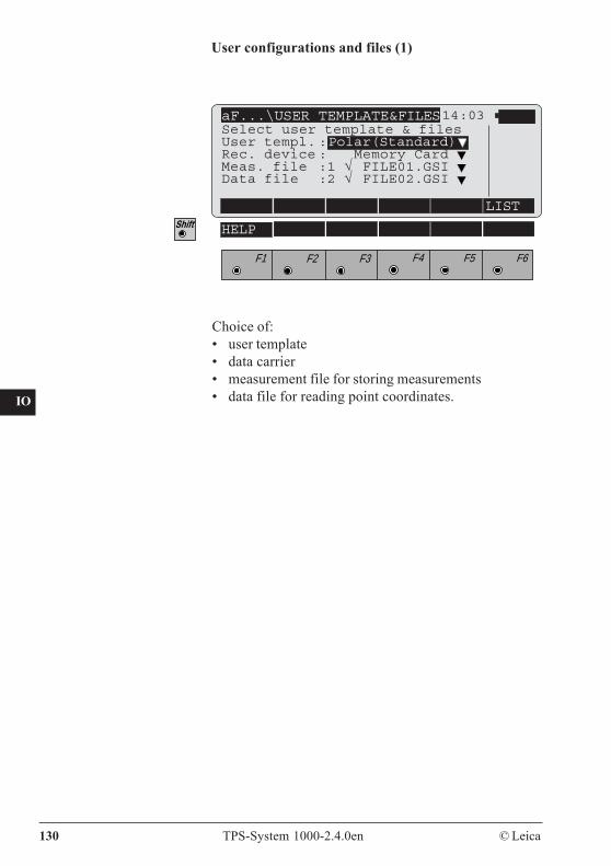
130 TPS-System 1000-2.4.0en © Leica
CO
IN
ID
PM
FS
SC
OC
IO
AR
RC
EG
CA
CT
BC
DF
SD
TS
IX
User configurations and files (1)
aF...\USER TEMPLATE&FILES14:03
LIST
F1 F2 F3 F4 F5 F6
HELP
Select user template & filesUser templ. :Polar(Standard)Rec. device : Memory Card Meas. file :1 √ FILE01.GSI Data file :2 √ FILE02.GSI
Choice of:• user template• data carrier• measurement file for storing measurements• data file for reading point coordinates.

CO
IN
ID
PM
FS
SC
OC
IO
AR
RC
EG
CA
CT
BC
DF
SD
TS
IX
© Leica TPS-System 1000-2.4.0en 131
Standard measurement. Accuracy 2mm + 2ppm (Type1800: 1mm + 2ppm). Time for a measurement: 3 sec.Normal distance measurement.
Precision measurement.Distance measurement with highest accuracy (1mm +2ppm). Time for a measurement: 3 sec.Only available for TCA1800 and DI2002.
Fast measurement. Accuracy 3mm +2ppm. Time for ameasurement: 1 sec.
Tracking.Continuous fast measurement. Accuracy 5mm +2ppm.Time for a measurement: 0.3 sec.
AverageRepeated measurement using normal mode, displayingthe number of distance measurements, continuousaverage and the standard deviation of the averageddistance. Time for a measurement: 3 sec.
Rapid tracking.Continuous measurement. Accuracy 10mm +2ppm.Time for a measurement: 0.15 sec.
aF...\EDM MEAS. PROGRAM 14:03
Select measuring program
EDM type : TCM1100active : Standard meas.
PRECI FAST TRK AVERG
F1 F2 F3 F4 F5 F6
HELP RTRK
EDM measuring program ( 2 )
Select the EDM measuring program required.
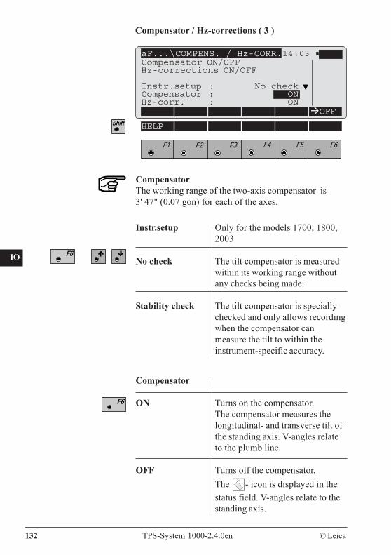
132 TPS-System 1000-2.4.0en © Leica
CO
IN
ID
PM
FS
SC
OC
IO
AR
RC
EG
CA
CT
BC
DF
SD
TS
IX
Instr.setup Only for the models 1700, 1800,2003
No check The tilt compensator is measuredwithin its working range withoutany checks being made.
Stability check The tilt compensator is speciallychecked and only allows recordingwhen the compensator canmeasure the tilt to within theinstrument-specific accuracy.
Compensator / Hz-corrections ( 3 )
aF...\COMPENS. / Hz-CORR.14:03
OFF
F1 F2 F3 F4 F5 F6
HELP
CompensatorThe working range of the two-axis compensator is3' 47" (0.07 gon) for each of the axes.
Compensator
ON Turns on the compensator.The compensator measures thelongitudinal- and transverse tilt ofthe standing axis. V-angles relateto the plumb line.
OFF Turns off the compensator.The - icon is displayed in thestatus field. V-angles relate to thestanding axis.
Compensator ON/OFFHz-corrections ON/OFF
Instr.setup : No checkCompensator : ONHz-corr. : ON
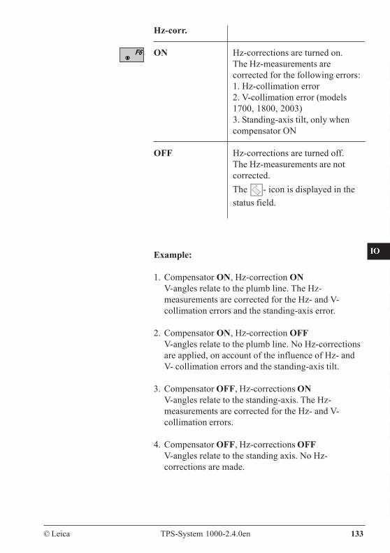
CO
IN
ID
PM
FS
SC
OC
IO
AR
RC
EG
CA
CT
BC
DF
SD
TS
IX
© Leica TPS-System 1000-2.4.0en 133
Hz-corr.
ON Hz-corrections are turned on.The Hz-measurements arecorrected for the following errors:1. Hz-collimation error2. V-collimation error (models1700, 1800, 2003)3. Standing-axis tilt, only whencompensator ON
OFF Hz-corrections are turned off.The Hz-measurements are notcorrected.The - icon is displayed in thestatus field.
Example:
1. Compensator ON, Hz-correction ONV-angles relate to the plumb line. The Hz-measurements are corrected for the Hz- and V-collimation errors and the standing-axis error.
2. Compensator ON, Hz-correction OFFV-angles relate to the plumb line. No Hz-correctionsare applied, on account of the influence of Hz- andV- collimation errors and the standing-axis tilt.
3. Compensator OFF, Hz-corrections ONV-angles relate to the standing-axis. The Hz-measurements are corrected for the Hz- and V-collimation errors.
4. Compensator OFF, Hz-corrections OFFV-angles relate to the standing axis. No Hz-corrections are made.
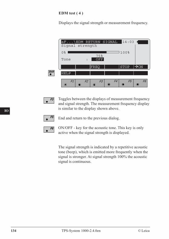
134 TPS-System 1000-2.4.0en © Leica
CO
IN
ID
PM
FS
SC
OC
IO
AR
RC
EG
CA
CT
BC
DF
SD
TS
IX
EDM test ( 4 )
Displays the signal strength or measurement frequency.
Toggles between the displays of measurement frequencyand signal strength. The measurement frequency displayis similar to the display shown above.
End and return to the previous dialog.
ON/OFF - key for the acoustic tone. This key is onlyactive when the signal strength is displayed.
The signal strength is indicated by a repetitive acoustictone (beep), which is emitted more frequently when thesignal is stronger. At signal strength 100% the acousticsignal is continuous.
aF...\EDM RETURN SIGNAL 14:03
FREQ STOP ON
F1 F2 F3 F4 F5 F6
HELP
Signal strength
0% 100%75%
Tone : OFF
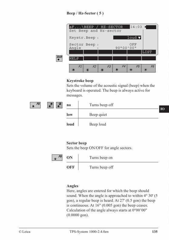
CO
IN
ID
PM
FS
SC
OC
IO
AR
RC
EG
CA
CT
BC
DF
SD
TS
IX
© Leica TPS-System 1000-2.4.0en 135
Beep / Hz-Sector ( 5 )
aF...\BEEP / HZ-SECTOR 14:03
LIST
F1 F2 F3 F4 F5 F6
HELP
Set Beep and Hz-sector
Keystr.Beep : loud
Sector Beep : OFFAngle : 90°00'00"
Sector beepSets the beep ON/OFF for angle sectors.
ON Turns beep on
OFF Turns beep off
AnglesHere, angles are entered for which the beep shouldsound. When the angle is approached to within 4° 30' (5gon), a regular beep is heard. At 27' (0.5 gon) the beepis continuous. At 16" (0.005 gon) the beep ceases.Calculation of the angle always starts at 0°00’00"(0.0000 gon).
Keystroke beepSets the volume of the acoustic signal (beep) when thekeyboard is operated. The beep is always active formessages.
no Turns beep off
low Beep quiet
loud Beep loud
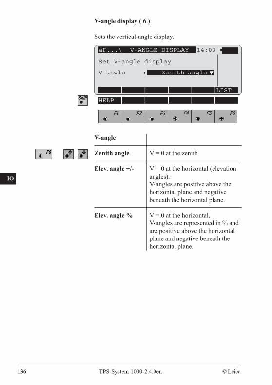
136 TPS-System 1000-2.4.0en © Leica
CO
IN
ID
PM
FS
SC
OC
IO
AR
RC
EG
CA
CT
BC
DF
SD
TS
IX
V-angle display ( 6 )
Sets the vertical-angle display.
aF...\ V-ANGLE DISPLAY 14:03
LIST
F1 F2 F3 F4 F5 F6
HELP
Set V-angle display
V-angle : Zenith angle
V-angle
Zenith angle V = 0 at the zenith
Elev. angle +/- V = 0 at the horizontal (elevationangles).V-angles are positive above thehorizontal plane and negativebeneath the horizontal plane.
Elev. angle % V = 0 at the horizontal.V-angles are represented in % andare positive above the horizontalplane and negative beneath thehorizontal plane.
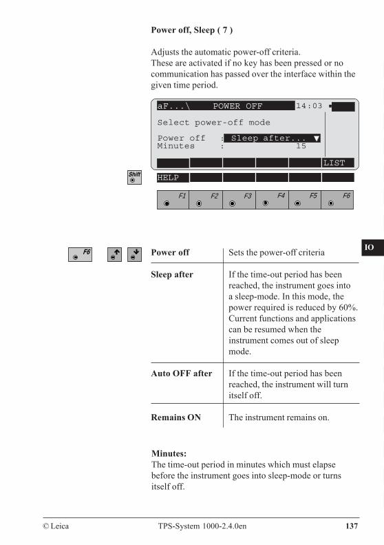
CO
IN
ID
PM
FS
SC
OC
IO
AR
RC
EG
CA
CT
BC
DF
SD
TS
IX
© Leica TPS-System 1000-2.4.0en 137
Power off, Sleep ( 7 )
Adjusts the automatic power-off criteria.These are activated if no key has been pressed or nocommunication has passed over the interface within thegiven time period.
aF...\ POWER OFF 14:03
LIST
F1 F2 F3 F4 F5 F6
HELP
Select power-off mode
Power off : Sleep after...Minutes : 15
Power off Sets the power-off criteria
Sleep after If the time-out period has beenreached, the instrument goes intoa sleep-mode. In this mode, thepower required is reduced by 60%.Current functions and applicationscan be resumed when theinstrument comes out of sleepmode.
Auto OFF after If the time-out period has beenreached, the instrument will turnitself off.
Remains ON The instrument remains on.
Minutes:The time-out period in minutes which must elapsebefore the instrument goes into sleep-mode or turnsitself off.
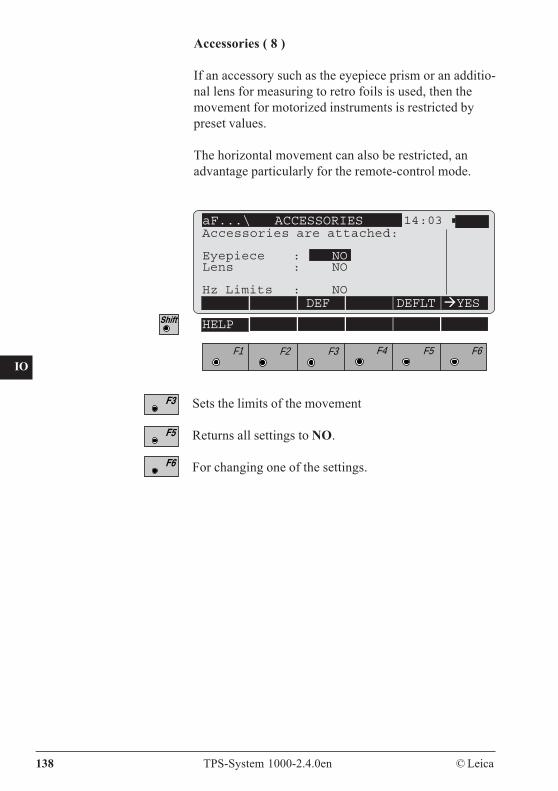
138 TPS-System 1000-2.4.0en © Leica
CO
IN
ID
PM
FS
SC
OC
IO
AR
RC
EG
CA
CT
BC
DF
SD
TS
IX
Accessories ( 8 )
If an accessory such as the eyepiece prism or an additio-nal lens for measuring to retro foils is used, then themovement for motorized instruments is restricted bypreset values.
The horizontal movement can also be restricted, anadvantage particularly for the remote-control mode.
aF...\ ACCESSORIES 14:03
DEF DEFLT YES
F1 F2 F3 F4 F5 F6
HELP
Accessories are attached:
Eyepiece : NOLens : NO
Hz Limits : NO
Sets the limits of the movement
Returns all settings to NO.
For changing one of the settings.
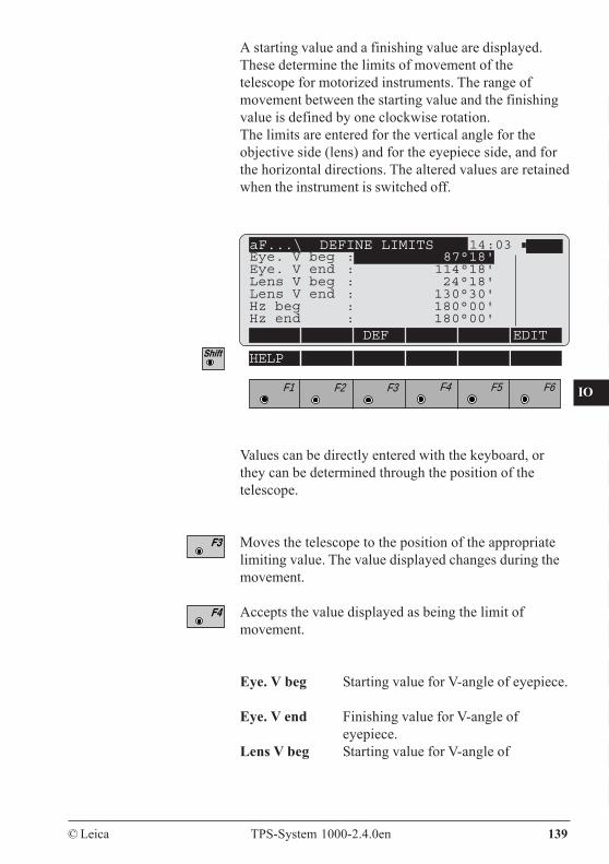
CO
IN
ID
PM
FS
SC
OC
IO
AR
RC
EG
CA
CT
BC
DF
SD
TS
IX
© Leica TPS-System 1000-2.4.0en 139
A starting value and a finishing value are displayed.These determine the limits of movement of thetelescope for motorized instruments. The range ofmovement between the starting value and the finishingvalue is defined by one clockwise rotation.The limits are entered for the vertical angle for theobjective side (lens) and for the eyepiece side, and forthe horizontal directions. The altered values are retainedwhen the instrument is switched off.
Values can be directly entered with the keyboard, orthey can be determined through the position of thetelescope.
Moves the telescope to the position of the appropriatelimiting value. The value displayed changes during themovement.
Accepts the value displayed as being the limit ofmovement.
Eye. V beg Starting value for V-angle of eyepiece.
Eye. V end Finishing value for V-angle ofeyepiece.
Lens V beg Starting value for V-angle of
aF...\ DEFINE LIMITS 14:03
DEF EDIT
F1 F2 F3 F4 F5 F6
HELP
Eye. V beg : 87°18'Eye. V end : 114°18'Lens V beg : 24°18'Lens V end : 130°30'Hz beg : 180°00'Hz end : 180°00'
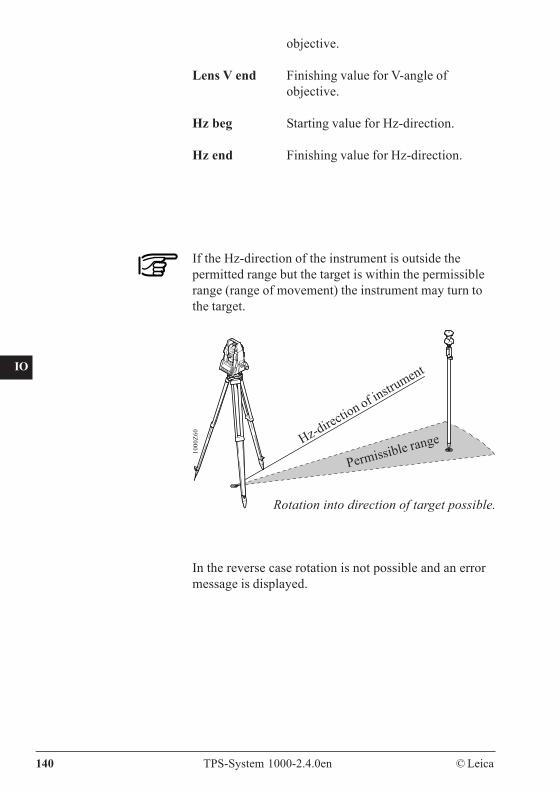
140 TPS-System 1000-2.4.0en © Leica
CO
IN
ID
PM
FS
SC
OC
IO
AR
RC
EG
CA
CT
BC
DF
SD
TS
IX
objective.
Lens V end Finishing value for V-angle ofobjective.
Hz beg Starting value for Hz-direction.
Hz end Finishing value for Hz-direction.
If the Hz-direction of the instrument is outside thepermitted range but the target is within the permissiblerange (range of movement) the instrument may turn tothe target.
In the reverse case rotation is not possible and an errormessage is displayed.
Hz-direction of instru
ment
Permissible range
1000
Z60
Rotation into direction of target possible.
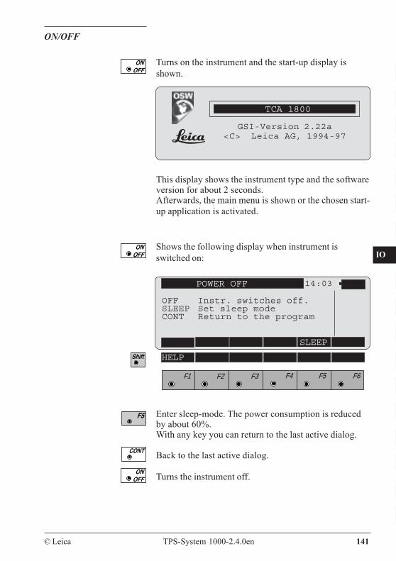
CO
IN
ID
PM
FS
SC
OC
IO
AR
RC
EG
CA
CT
BC
DF
SD
TS
IX
© Leica TPS-System 1000-2.4.0en 141
ON/OFF
TCA 1800
GSI-Version 2.22a<C> Leica AG, 1994-97
Turns on the instrument and the start-up display isshown.
This display shows the instrument type and the softwareversion for about 2 seconds.Afterwards, the main menu is shown or the chosen start-up application is activated.
POWER OFF 14:03
OFF Instr. switches off.SLEEP Set sleep modeCONT Return to the program
SLEEP
F1 F2 F3 F4 F5 F6
HELP
Enter sleep-mode. The power consumption is reducedby about 60%.With any key you can return to the last active dialog.
Back to the last active dialog.
Turns the instrument off.
Shows the following display when instrument isswitched on:
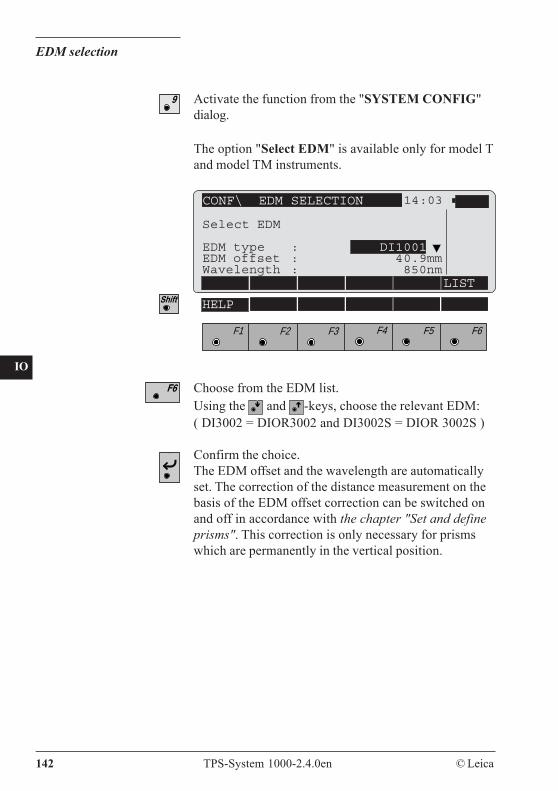
142 TPS-System 1000-2.4.0en © Leica
CO
IN
ID
PM
FS
SC
OC
IO
AR
RC
EG
CA
CT
BC
DF
SD
TS
IX
EDM selection
CONF\ EDM SELECTION 14:03
Select EDM
EDM type : DI1001EDM offset : 40.9mmWavelength : 850nm
LIST
F1 F2 F3 F4 F5 F6
HELP
The option "Select EDM" is available only for model Tand model TM instruments.
Choose from the EDM list.Using the and -keys, choose the relevant EDM:( DI3002 = DIOR3002 and DI3002S = DIOR 3002S )
Confirm the choice.The EDM offset and the wavelength are automaticallyset. The correction of the distance measurement on thebasis of the EDM offset correction can be switched onand off in accordance with the chapter "Set and defineprisms". This correction is only necessary for prismswhich are permanently in the vertical position.
Activate the function from the "SYSTEM CONFIG"dialog.
© Leica TPS-System 1000-2.4.0en 143
CO
IN
ID
PM
FS
SC
OC
IO
AR
RC
EG
CA
CT
BC
DF
SD
TS
IX
Automatic Target Recognition
TCA instruments are motorized and equipped withAutomatic Target Recognition (ATR1) coaxially in thetelescope. The EGL1 guide light, mounted on thetelescope, is optional.These instruments permit automatic angle and distancemeasurements to normal prisms and reduce the tediumof precise visual sighting to prisms.The prism is sighted with the optical sight only.Initiating a distance measurement will turn theinstrument with the help of the motors to sight theprism-centre automatically.The angles V and Hz are measured to the centre of theprism at the completion of the distance measurement.
As with all other instrument errors, the collimation errorof the automatic target recognition (ATR1) must beredetermined periodically (Refer to chapter "Checkingand Adjusting").
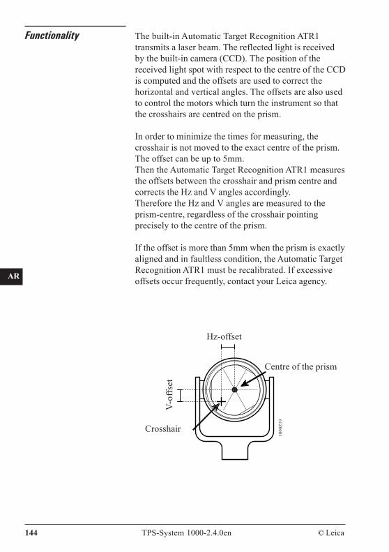
CO
IN
ID
PM
FS
SC
OC
IO
AR
RC
EG
CA
CT
BC
DF
SD
TS
IX
144 TPS-System 1000-2.4.0en © Leica
Functionality The built-in Automatic Target Recognition ATR1transmits a laser beam. The reflected light is receivedby the built-in camera (CCD). The position of thereceived light spot with respect to the centre of the CCDis computed and the offsets are used to correct thehorizontal and vertical angles. The offsets are also usedto control the motors which turn the instrument so thatthe crosshairs are centred on the prism.
In order to minimize the times for measuring, thecrosshair is not moved to the exact centre of the prism.The offset can be up to 5mm.Then the Automatic Target Recognition ATR1 measuresthe offsets between the crosshair and prism centre andcorrects the Hz and V angles accordingly.Therefore the Hz and V angles are measured to theprism-centre, regardless of the crosshair pointingprecisely to the centre of the prism.
If the offset is more than 5mm when the prism is exactlyaligned and in faultless condition, the Automatic TargetRecognition ATR1 must be recalibrated. If excessiveoffsets occur frequently, contact your Leica agency.
Hz-offset
1000
Z19
Centre of the prism
Crosshair
V-of
fset
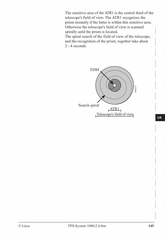
© Leica TPS-System 1000-2.4.0en 145
CO
IN
ID
PM
FS
SC
OC
IO
AR
RC
EG
CA
CT
BC
DF
SD
TS
IX
The sensitive area of the ATR1 is the central third of thetelescope's field of view. The ATR1 recognizes theprism instantly if the latter is within this sensitive area.Otherwise the telescope's field of view is scannedspirally until the prism is located.The spiral search of the field of view of the telescope,and the recognition of the prism, together take about2 - 4 seconds.
1000
Z20
EDM
Telescope's field of viewATR1
Search spiral
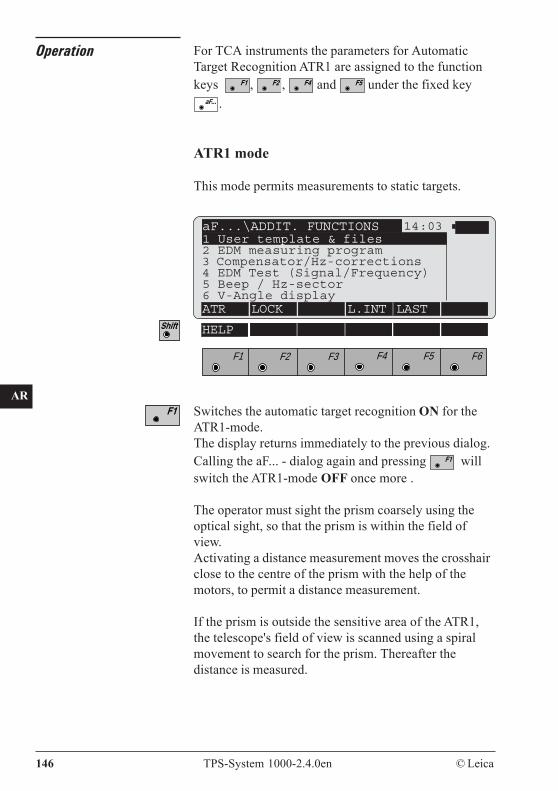
CO
IN
ID
PM
FS
SC
OC
IO
AR
RC
EG
CA
CT
BC
DF
SD
TS
IX
146 TPS-System 1000-2.4.0en © Leica
Operation For TCA instruments the parameters for AutomaticTarget Recognition ATR1 are assigned to the functionkeys , , and under the fixed key
aF... .
ATR1 mode
This mode permits measurements to static targets.
aF...\ADDIT. FUNCTIONS 14:03
ATR LOCK L.INT LAST
HELP
F1 F2 F3 F4 F5 F6
Switches the automatic target recognition ON for theATR1-mode.The display returns immediately to the previous dialog.Calling the aF... - dialog again and pressing willswitch the ATR1-mode OFF once more .
The operator must sight the prism coarsely using theoptical sight, so that the prism is within the field ofview.Activating a distance measurement moves the crosshairclose to the centre of the prism with the help of themotors, to permit a distance measurement.
If the prism is outside the sensitive area of the ATR1,the telescope's field of view is scanned using a spiralmovement to search for the prism. Thereafter thedistance is measured.
1 User template & files2 EDM measuring program3 Compensator/Hz-corrections4 EDM Test (Signal/Frequency)5 Beep / Hz-sector6 V-Angle display
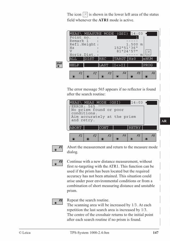
© Leica TPS-System 1000-2.4.0en 147
CO
IN
ID
PM
FS
SC
OC
IO
AR
RC
EG
CA
CT
BC
DF
SD
TS
IX
The icon is shown in the lower left area of the statusfield whenever the ATR1 mode is active.
MEAS\ MEASURE MODE (GSI) 14:03
ALL DIST REC TARGT Hz0 αNUM
HELP LAST I<>II PROG
F1 F2 F3 F4 F5 F6
Point no. : 1Remark 1 : -----Refl.Height : 1.500 mHz : 152°51'36"V : 81°24'57"Horiz.Dist. : ----- m
The error message 565 appears if no reflector is foundafter the search routine:
MEAS\ MEAS MODE (GSI) 14:03ERROR: 565No prism found or poorconditions.Aim accurately at the prismand retry.
ABORT CONT RETRY
F1 F2 F3 F4 F5 F6
Abort the measurement and return to the measure modedialog.
Continue with a new distance measurement, withoutfirst re-targeting with the ATR1. This function can beused if the prism has been located but the requiredaccuracy has not been attained. This situation couldarise under poor environmental conditions or from acombination of short measuring distance and unstableprism.
Repeat the search routine.The scanning area will be increased by 1/3. At eachrepetition the last search area is increased by 1/3.The centre of the crosshair returns to the initial pointafter each search routine if no prism is found.
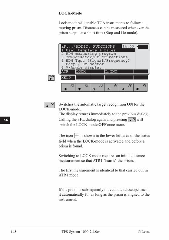
CO
IN
ID
PM
FS
SC
OC
IO
AR
RC
EG
CA
CT
BC
DF
SD
TS
IX
148 TPS-System 1000-2.4.0en © Leica
LOCK-Mode
Lock-mode will enable TCA instruments to follow amoving prism. Distances can be measured whenever theprism stops for a short time (Stop and Go mode).
aF...\ADDIT. FUNCTIONS 14:031 User template & files2 EDM measuring program3 Compensator/Hz-corrections4 EDM Test (Signal/Frequency)5 Beep / Hz-sector6 V-Angle displayATR LOCK L.INT
HELP
F1 F2 F3 F4 F5 F6
Switches the automatic target recognition ON for theLOCK-mode.The display returns immediately to the previous dialog.Calling the aF... dialog again and pressing willswitch the LOCK-mode OFF once more.
The icon is shown in the lower left area of the statusfield when the LOCK-mode is activated and before aprism is found.
Switching to LOCK mode requires an initial distancemeasurement so that ATR1 "learns" the prism.
The first measurement is identical to that carried out inATR1 mode.
If the prism is subsequently moved, the telescope tracksit automatically for as long as the prism is aligned to theinstrument.
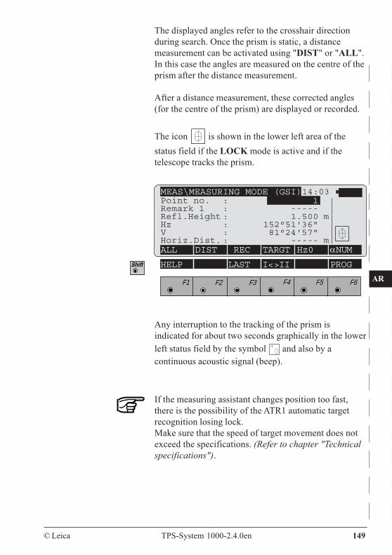
© Leica TPS-System 1000-2.4.0en 149
CO
IN
ID
PM
FS
SC
OC
IO
AR
RC
EG
CA
CT
BC
DF
SD
TS
IX
The displayed angles refer to the crosshair directionduring search. Once the prism is static, a distancemeasurement can be activated using "DIST" or "ALL".In this case the angles are measured on the centre of theprism after the distance measurement.
After a distance measurement, these corrected angles(for the centre of the prism) are displayed or recorded.
The icon is shown in the lower left area of thestatus field if the LOCK mode is active and if thetelescope tracks the prism.
If the measuring assistant changes position too fast,there is the possibility of the ATR1 automatic targetrecognition losing lock.Make sure that the speed of target movement does notexceed the specifications. (Refer to chapter "Technicalspecifications").
MEAS\MEASURING MODE (GSI)14:03
ALL DIST REC TARGT Hz0 αNUM
F1 F2 F3 F4 F5 F6
HELP LAST I<>II PROG
Point no. : 1Remark 1 : -----Refl.Height : 1.500 mHz : 152°51'36"V : 81°24'57"Horiz.Dist. : ----- m
Any interruption to the tracking of the prism isindicated for about two seconds graphically in the lowerleft status field by the symbol and also by acontinuous acoustic signal (beep).
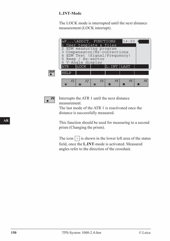
CO
IN
ID
PM
FS
SC
OC
IO
AR
RC
EG
CA
CT
BC
DF
SD
TS
IX
150 TPS-System 1000-2.4.0en © Leica
L.INT-Mode
The LOCK mode is interrupted until the next distancemeasurement (LOCK interrupt).
aF...\ADDIT. FUNCTIONS 14:031 User template & files2 EDM measuring program3 Compensator/Hz-corrections4 EDM Test (Signal/Frequency)5 Beep / Hz-sector6 V-Angle displayATR LOCK L.INT LAST
HELP
F1 F2 F3 F4 F5 F6
Interrupts the ATR 1 until the next distancemeasurement.The last mode of the ATR 1 is reactivated once thedistance is successfully measured.
This function should be used for measuring to a secondprism (Changing the prism).
The icon is shown in the lower left area of the statusfield, once the L.INT-mode is activated. Measuredangles refer to the direction of the crosshair.
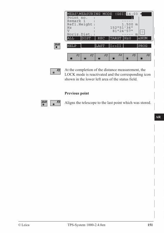
© Leica TPS-System 1000-2.4.0en 151
CO
IN
ID
PM
FS
SC
OC
IO
AR
RC
EG
CA
CT
BC
DF
SD
TS
IX
MEAS\MEASURING MODE (GSI)14:03
ALL DIST REC TARGT Hz0 αNUM
HELP LAST I<>II PROG
F1 F2 F3 F4 F5 F6
At the completion of the distance measurement, theLOCK mode is reactivated and the corresponding iconshown in the lower left area of the status field.
Previous point
Aligns the telescope to the last point which was stored.
Point no. : 1Remark 1 : -----Refl.Height : 1.500 mHz : 152°51'36"V : 81°24'57"Horiz.Dist. : ----- m
CO
IN
ID
PM
FS
SC
OC
IO
AR
RC
EG
CA
CT
BC
DF
SD
TS
IX
152 TPS-System 1000-2.4.0en © Leica
Automatic TargetRecognition ATR1resolution modes
The accuracy with which the position of a prism can bedetermined with Automatic Target Recognition ATR1 isdependent on the internal accuracy of the ATR1 itself,and on the external accuracy, which is affected inparticular by the type of prism and by the ambientbrightness. The external accuracy is attained if themeasurement is repeated at intervals.The internal accuracy of the ATR1 depends on theresolution of the CCD camera, on the time for themeasurement, on the condition and position of theprism, and on other factors; it is the accuracy obtainableunder optimum conditions at one particular time.
Generally, the accuracy of the ATR and of the anglemeasurement are the same. Under a certain distance,however, ATR accuracy predominates. That distance isdetermined by the angle accuracy of the instrument.
The external accuracy of a prism-position determinationis important to the user and is +/-2mm in the standardEDM measuring mode for Leica circular prisms or +/-1mm in the precision EDM measuring mode. For the360° reflector it is +/-5mm each for the transverse andvertical component.
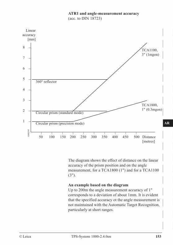
© Leica TPS-System 1000-2.4.0en 153
CO
IN
ID
PM
FS
SC
OC
IO
AR
RC
EG
CA
CT
BC
DF
SD
TS
IX
The diagram shows the effect of distance on the linearaccuracy of the prism position and on the anglemeasurement, for a TCA1800 (1") and for a TCA1100(3").
An example based on the diagramUp to 200m the angle measurement accuracy of 1"corresponds to a deviation of about 1mm. It is evidentthat the specified accuracy ot the angle measurement isnot maintained with the Automatic Target Recognition,particularly at short ranges.
ATR1 and angle-measurement accuracy(acc. to DIN 18723)
8
7
6
5
4
3
2
1 Circular prism (precision mode)
50 100 150 200 250 300 350 400 450 500 Distance[metres]
360° reflector
Circular prism (standard mode)
1000
Z45
Linearaccuracy
[mm]
TCA1800,1" (0.3mgon)
TCA1100,3" (1mgon)
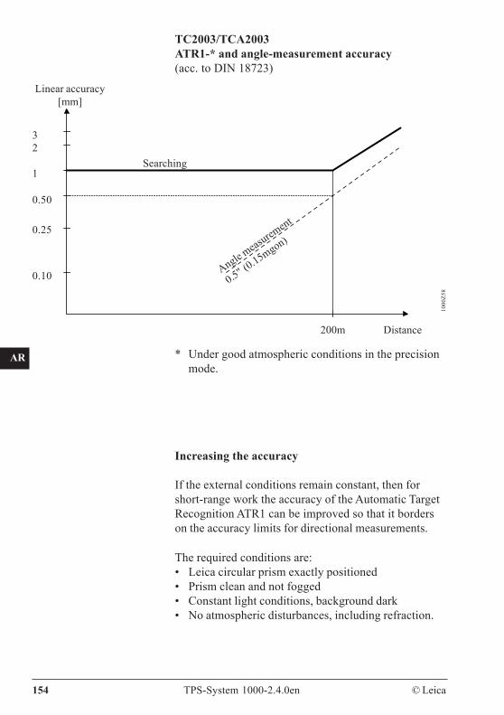
CO
IN
ID
PM
FS
SC
OC
IO
AR
RC
EG
CA
CT
BC
DF
SD
TS
IX
154 TPS-System 1000-2.4.0en © Leica
TC2003/TCA2003ATR1-* and angle-measurement accuracy(acc. to DIN 18723)
200m Distance
32
1
0.50
0.25
0.10
1000
Z58
Searching
Angle meas
urement
0.5" (0.15mgon)
* Under good atmospheric conditions in the precisionmode.
Linear accuracy[mm]
Increasing the accuracy
If the external conditions remain constant, then forshort-range work the accuracy of the Automatic TargetRecognition ATR1 can be improved so that it borderson the accuracy limits for directional measurements.
The required conditions are:• Leica circular prism exactly positioned• Prism clean and not fogged• Constant light conditions, background dark• No atmospheric disturbances, including refraction.
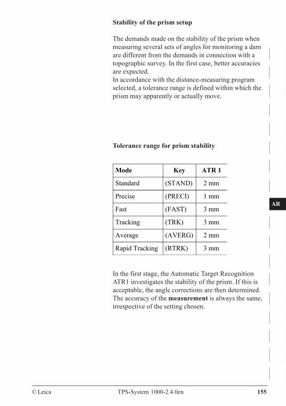
© Leica TPS-System 1000-2.4.0en 155
CO
IN
ID
PM
FS
SC
OC
IO
AR
RC
EG
CA
CT
BC
DF
SD
TS
IX
Stability of the prism setup
The demands made on the stability of the prism whenmeasuring several sets of angles for monitoring a damare different from the demands in connection with atopographic survey. In the first case, better accuraciesare expected.In accordance with the distance-measuring programselected, a tolerance range is defined within which theprism may apparently or actually move.
Tolerance range for prism stability
In the first stage, the Automatic Target RecognitionATR1 investigates the stability of the prism. If this isacceptable, the angle corrections are then determined.The accuracy of the measurement is always the same,irrespective of the setting chosen.
Mode Key ATR 1
Standard (STAND) 2 mm
Precise (PRECI) 1 mm
Fast (FAST) 3 mm
Tracking (TRK) 3 mm
Average (AVERG) 2 mm
Rapid Tracking (RTRK) 3 mm
CO
IN
ID
PM
FS
SC
OC
IO
AR
RC
EG
CA
CT
BC
DF
SD
TS
IX
156 TPS-System 1000-2.4.0en © Leica
Information on the useof Automatic TargetRecognition ATR1
General
The range of automatic target recognition can berestricted, and its functioning impaired, by variousexternal factors.
There follows here a description of the causes, of theresulting error reports, and of possible counter-measures.
The accuracy for the target point recognition of theTCA is determined by the selection of the EDMmeasuring mode. The highest accuracy for the targetpoint recognition by the ATR is obtained in theprecision mode (PRECI).The setting PRECI must be selected for the TCA2003in order to reach the specified angle measurementaccuracy of 0.5" (0.15 mgon) during target recognitionmeasurements.During measurements in this mode it is possible that themeasuring period is prolonged up to about one second.
© Leica TPS-System 1000-2.4.0en 157
CO
IN
ID
PM
FS
SC
OC
IO
AR
RC
EG
CA
CT
BC
DF
SD
TS
IX
Reduction of the range Reduction of the range under the followingunfavourable atmospheric conditions:• Hot sunny weather• Strong heat shimmer• Bright reflections of the sun in the field of view.
Such "hot-spots" can also be produced outside thefocusing range by vehicles and other shiny objects.
Counter-measures:
• Reduce the measurement distance• Cover bright reflections• Measure without Automatic Target Recognition
ATR1,i.e., after the error report "No prism found ...",target manually and trigger distance measurementwith .
Atmospheric conditions influence the range of theATR1 more than that of the EDM, and so the range datafor the ATR1 are only approximate.
CO
IN
ID
PM
FS
SC
OC
IO
AR
RC
EG
CA
CT
BC
DF
SD
TS
IX
158 TPS-System 1000-2.4.0en © Leica
Disturbance Disturbance in ATR1 mode or at start of LOCKmode(The ATR1 is unable to recognize the prism)This may be due to various causes and may provokevarious error reports:
• "No prism found or bad conditions. Aimaccurately at the prism and retry."
Causes:- No prism in field of view of telescope- Strong heat shimmer- Measurement distance too great- Environment too bright (sunshine on bright
surfaces, e.g. snow)- Bright reflections of sun in field of view, close to
prism.
In the two last instances, the report "Interferingreflection" may also appear.
Counter-measures:- Reduce measurement distance- Cover reflections- Measure without Automatic Target Recognition
ATR1
• "Multiple prism found ! Aim more accurately atthe prism."
Causes:- Several prisms in field of view- Raindrops on prism or on object lens of
telescope
Counter-measures:- Ensure that only one prism is in field of view- Remove raindrops
© Leica TPS-System 1000-2.4.0en 159
CO
IN
ID
PM
FS
SC
OC
IO
AR
RC
EG
CA
CT
BC
DF
SD
TS
IX
Raindrops, condensation or dirt on the prism may resultin the quoted accuracy not being reached with theautomatic target recognition, because the target point ofthe ATR1 will be displaced as a result.
• "Position not achieved. Time out of positioningsystem, prism unstable, air shimmer or othererror. Try again."(The ATR1 cannot attain the positioning precisionrequired)
Cause:- Oscillation of the reflector pole at short distances
Counter-measures:- Hold reflector pole still or support it.- Measure without Automatic Target Recognition
ATR1- Select a different DISTANCE-MEASURING
PROGRAM.
Disturbance of target tracking in LOCK mode
Causes:- Measurement distance too great- Bright reflection close to prism (instrument tracks
reflection)- Highly-fluctuating ambient brightness or strong heat
shimmer (instrument trembles or turns away fromprism)
Counter-measures:- Reduce measurement distance- Target prism manually and restart LOCK
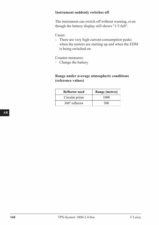
CO
IN
ID
PM
FS
SC
OC
IO
AR
RC
EG
CA
CT
BC
DF
SD
TS
IX
160 TPS-System 1000-2.4.0en © Leica
Instrument suddenly switches off
The instrument can switch off without warning, eventhough the battery display still shows "1/3 full".
Cause:- There are very high current-consumption peaks
when the motors are starting up and when the EDMis being switched on.
Counter-measures:- Change the battery
Range under average atmospheric conditions(reference values)
Reflector used Range [metres]Circular prism 1000
360° reflector 500
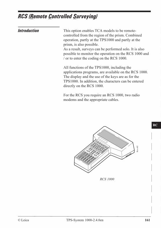
CO
IN
ID
PM
FS
SC
OC
IO
AR
RC
EG
CA
CT
BC
DF
SD
TS
IX
© Leica TPS-System 1000-2.4.0en 161
RCS (Remote Controlled Surveying)
Introduction This option enables TCA models to be remote-controlled from the region of the prism. Combinedoperation, partly at the TPS1000 and partly at theprism, is also possible.As a result, surveys can be performed solo. It is alsopossible to monitor the operation on the RCS 1000 and/ or to enter the coding on the RCS 1000.
All functions of the TPS1000, including theapplications programs, are available on the RCS 1000.The display and the use of the keys are as for theTPS1000. In addition, the characters can be entereddirectly on the RCS 1000.
For the RCS you require an RCS 1000, two radiomodems and the appropriate cables.
Rcs
-z02
RCS 1000
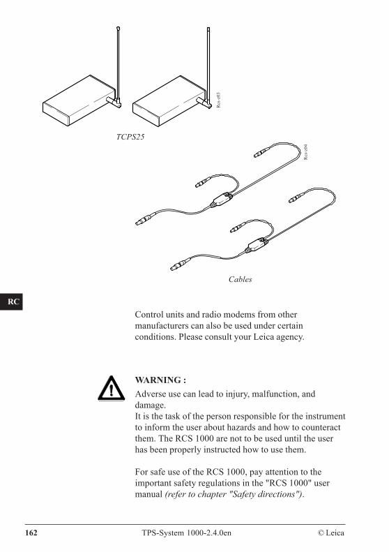
CO
IN
ID
PM
FS
SC
OC
IO
AR
RC
EG
CA
CT
BC
DF
SD
TS
IX
162 TPS-System 1000-2.4.0en © Leica
Rcs
-z03
TCPS25
Rcs
-z04
Cables
Control units and radio modems from othermanufacturers can also be used under certainconditions. Please consult your Leica agency.
WARNING :Adverse use can lead to injury, malfunction, anddamage.It is the task of the person responsible for the instrumentto inform the user about hazards and how to counteractthem. The RCS 1000 are not to be used until the userhas been properly instructed how to use them.
For safe use of the RCS 1000, pay attention to theimportant safety regulations in the "RCS 1000" usermanual (refer to chapter "Safety directions").
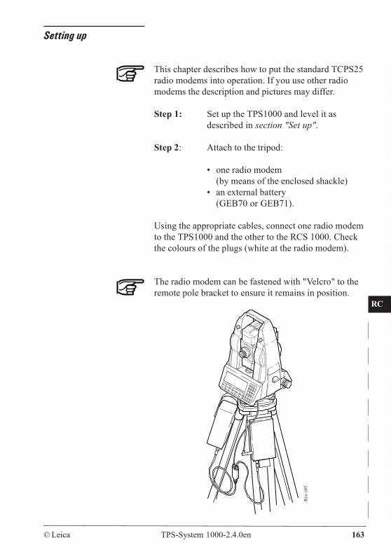
CO
IN
ID
PM
FS
SC
OC
IO
AR
RC
EG
CA
CT
BC
DF
SD
TS
IX
© Leica TPS-System 1000-2.4.0en 163
Setting up
This chapter describes how to put the standard TCPS25radio modems into operation. If you use other radiomodems the description and pictures may differ.
Step 1: Set up the TPS1000 and level it asdescribed in section "Set up".
Step 2: Attach to the tripod:
• one radio modem(by means of the enclosed shackle)
• an external battery(GEB70 or GEB71).
Using the appropriate cables, connect one radio modemto the TPS1000 and the other to the RCS 1000. Checkthe colours of the plugs (white at the radio modem).
The radio modem can be fastened with "Velcro" to theremote pole bracket to ensure it remains in position.
Rcs
-z05
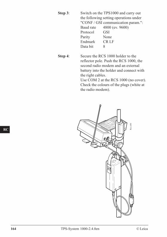
CO
IN
ID
PM
FS
SC
OC
IO
AR
RC
EG
CA
CT
BC
DF
SD
TS
IX
164 TPS-System 1000-2.4.0en © Leica
Step 3: Switch on the TPS1000 and carry outthe following setting operations under"CONF / GSI communication param.":Baud rate 4800 (ev. 9600)Protocol GSIParity NoneEndmark CR LFData bit 8
Step 4: Secure the RCS 1000 holder to thereflector pole. Push the RCS 1000, thesecond radio modem and an externalbattery into the holder and connect withthe right cables.Use COM 2 at the RCS 1000 (no cover).Check the colours of the plugs (white atthe radio modem).
Rcs
-z06
CO
IN
ID
PM
FS
SC
OC
IO
AR
RC
EG
CA
CT
BC
DF
SD
TS
IX
© Leica TPS-System 1000-2.4.0en 165
Step 5: Select remote-control mode from mainmenu of TPS1000:
(EXTRA) / (remote-controlmode) / (YES)
Step 6: Switch on the RCS 1000 and start theprogram by pressing Check the communication parameters asdescribed in chapter "RCS1000".Now, the RCS 1000 is ready to receivedata from the TPS1000.
The TPS1000 is now ready. It receives all orders fromthe RCS 1000 and sends the contents of the display tothe RCS 1000. The data are recorded on the PCMCIAcard of the TPS1000, as in the normal operation mode.No provision is made for using the RS232 interface forstoring data on the RCS 1000.
The keys shown in this chapter correspond with thekeys of the RCS 1000. Only at "step 5" the keys of theTPS 1000 are depicted.
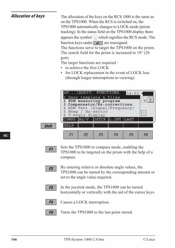
CO
IN
ID
PM
FS
SC
OC
IO
AR
RC
EG
CA
CT
BC
DF
SD
TS
IX
166 TPS-System 1000-2.4.0en © Leica
Allocation of keys The allocation of the keys on the RCS 1000 is the same ason the TPS1000. When the RCS is switched on, theTPS1000 automatically changes to LOCK mode (prismtracking). In the status field on the TPS1000 display thereappears the symbol which signifies the RCS mode. Thefunction keys under are reassigned.The functions serve to target the TPS1000 on the prism.The search field for the prism is increased to 18° (20gon).The target functions are required :• to achieve the first LOCK• for LOCK replacement in the event of LOCK loss
(through longer interruptions to viewing).
Sets the TPS1000 to compass mode, enabling theTPS1000 to be targeted on the prism with the help of acompass.
By entering relative or absolute angle values, theTPS1000 can be turned by the corresponding amount orset to the angle value required.
In the joystick mode, the TPS1000 can be turnedhorizontally or vertically with the aid of the cursor keys.
Causes a LOCK interruption.
Turns the TPS1000 to the last point stored.
14:03
HELP
MC1 User template & files
2 EDM measuring program3 Compensator/Hz-corrections4 EDM Test (Signal/Frequency)5 Beep / Hz-sector6 V-Angle displayCOMPS Hz/V JSTCK L.INT LAST
aF...\ADDIT. FUNCTIONS
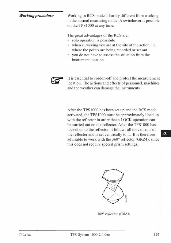
CO
IN
ID
PM
FS
SC
OC
IO
AR
RC
EG
CA
CT
BC
DF
SD
TS
IX
© Leica TPS-System 1000-2.4.0en 167
Working procedure Working in RCS mode is hardly different from workingin the normal measuring mode. A switchover is possibleon the TPS1000 at any time.
The great advantages of the RCS are:• solo operation is possibile• when surveying you are at the site of the action, i.e.
where the points are being recorded or set out• you do not have to assess the situation from the
instrument location.
It is essential to cordon-off and protect the measurementlocation. The actions and effects of personnel, machinesand the weather can damage the instruments.
After the TPS1000 has been set up and the RCS modeactivated, the TPS1000 must be approximately lined upwith the reflector in order that a LOCK operation canbe carried out on the reflector. After the TPS1000 haslocked on to the reflector, it follows all movements ofthe reflector and is set centrically to it. It is thereforeadvisable to work with the 360° reflector (GRZ4), sincethis does not require special prism settings.
1000
Z25
360° reflector (GRZ4)
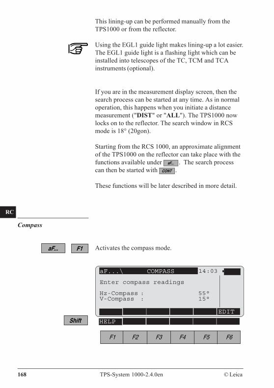
CO
IN
ID
PM
FS
SC
OC
IO
AR
RC
EG
CA
CT
BC
DF
SD
TS
IX
168 TPS-System 1000-2.4.0en © Leica
This lining-up can be performed manually from theTPS1000 or from the reflector.
Using the EGL1 guide light makes lining-up a lot easier.The EGL1 guide light is a flashing light which can beinstalled into telescopes of the TC, TCM and TCAinstruments (optional).
If you are in the measurement display screen, then thesearch process can be started at any time. As in normaloperation, this happens when you initiate a distancemeasurement ("DIST" or "ALL"). The TPS1000 nowlocks on to the reflector. The search window in RCSmode is 18° (20gon).
Starting from the RCS 1000, an approximate alignmentof the TPS1000 on the reflector can take place with thefunctions available under . The search processcan then be started with .
These functions will be later described in more detail.
Compass
Activates the compass mode.
HELP
aF...\ COMPASS 14:03
EDIT
Enter compass readings
Hz-Compass : 55°V-Compass : 15°
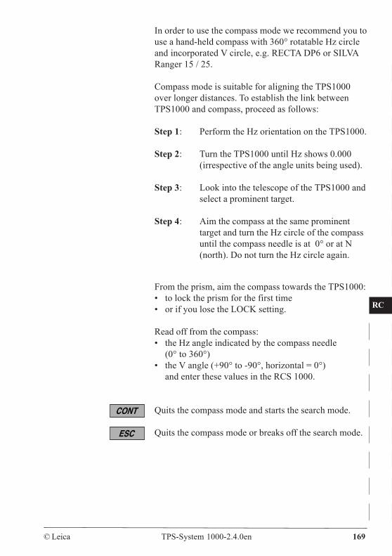
CO
IN
ID
PM
FS
SC
OC
IO
AR
RC
EG
CA
CT
BC
DF
SD
TS
IX
© Leica TPS-System 1000-2.4.0en 169
In order to use the compass mode we recommend you touse a hand-held compass with 360° rotatable Hz circleand incorporated V circle, e.g. RECTA DP6 or SILVARanger 15 / 25.
Compass mode is suitable for aligning the TPS1000over longer distances. To establish the link betweenTPS1000 and compass, proceed as follows:
Step 1: Perform the Hz orientation on the TPS1000.
Step 2: Turn the TPS1000 until Hz shows 0.000(irrespective of the angle units being used).
Step 3: Look into the telescope of the TPS1000 andselect a prominent target.
Step 4: Aim the compass at the same prominenttarget and turn the Hz circle of the compassuntil the compass needle is at 0° or at N(north). Do not turn the Hz circle again.
From the prism, aim the compass towards the TPS1000:• to lock the prism for the first time• or if you lose the LOCK setting.
Read off from the compass:• the Hz angle indicated by the compass needle
(0° to 360°)• the V angle (+90° to -90°, horizontal = 0°)
and enter these values in the RCS 1000.
Quits the compass mode and starts the search mode.
Quits the compass mode or breaks off the search mode.
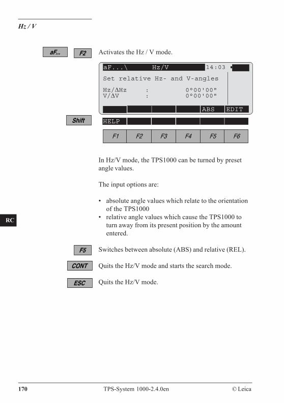
CO
IN
ID
PM
FS
SC
OC
IO
AR
RC
EG
CA
CT
BC
DF
SD
TS
IX
170 TPS-System 1000-2.4.0en © Leica
Hz / V
Activates the Hz / V mode.
In Hz/V mode, the TPS1000 can be turned by presetangle values.
The input options are:
• absolute angle values which relate to the orientationof the TPS1000
• relative angle values which cause the TPS1000 toturn away from its present position by the amountentered.
Switches between absolute (ABS) and relative (REL).
Quits the Hz/V mode and starts the search mode.
Quits the Hz/V mode.
HELP
aF...\ Hz/V 14:03
ABS EDIT
Set relative Hz- and V-angles
Hz/ΔHz : 0°00'00"V/ΔV : 0°00'00"
CO
IN
ID
PM
FS
SC
OC
IO
AR
RC
EG
CA
CT
BC
DF
SD
TS
IX
© Leica TPS-System 1000-2.4.0en 171
Joystick
Activates the joystick mode.
HELP
In the joystick mode, the cursor keys on the RCS 1000can be used to turn the TPS1000. The EGL1 guidelight, if available, is switched on automatically.
Turns telescope slowly to the right ( left)
Turns telescope rapidly to the right ( left)
Turns telescope slowly upwards ( downwards)
Turns telescope rapidly upwards ( downwards)
To stop the rotary movement, press any cursor key.
Quits joystick mode and starts search mode
Quits joystick mode or breaks off the search
aF...\JOYSTICK MOVEMENT 14:03
Use cursor keys
Hz/ΔHz : 3°24'V/ΔV : 92°56'
CO
IN
ID
PM
FS
SC
OC
IO
AR
RC
EG
CA
CT
BC
DF
SD
TS
IX
172 TPS-System 1000-2.4.0en © Leica
Lock interruption
Activates the lock interruption.
This function serves to interrupt the LOCK mode andlater to reinstate it, e.g. before the prism is placed on theground during setting-out or if the TPS1000 is also tobe targeted on a second prism.
Last point stored
Activates the LAST function.
If the LOCK mode is lost, this function can be used toturn the TPS1000 back to the last point stored. Whenthe movement is complete, the TPS1000 automaticallystarts to search for the prism.
Stops search mode.
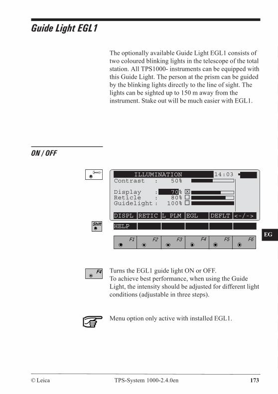
CO
IN
ID
PM
FS
SC
OC
IO
AR
RC
EG
CA
CT
BC
DF
SD
TS
IX
© Leica TPS-System 1000-2.4.0en 173
The optionally available Guide Light EGL1 consists oftwo coloured blinking lights in the telescope of the totalstation. All TPS1000- instruments can be equipped withthis Guide Light. The person at the prism can be guidedby the blinking lights directly to the line of sight. Thelights can be sighted up to 150 m away from theinstrument. Stake out will be much easier with EGL1.
Guide Light EGL1
ON / OFF
ILLUMINATION 14:03Contrast : 50%
Display : 70% ⌧Reticle : 80%Guidelight : 100%
DISPL RETIC L_PLM EGL DEFLT <-/->
F1 F2 F3 F4 F5 F6
HELP
Turns the EGL1 guide light ON or OFF.To achieve best performance, when using the GuideLight, the intensity should be adjusted for different lightconditions (adjustable in three steps).
Menu option only active with installed EGL1.
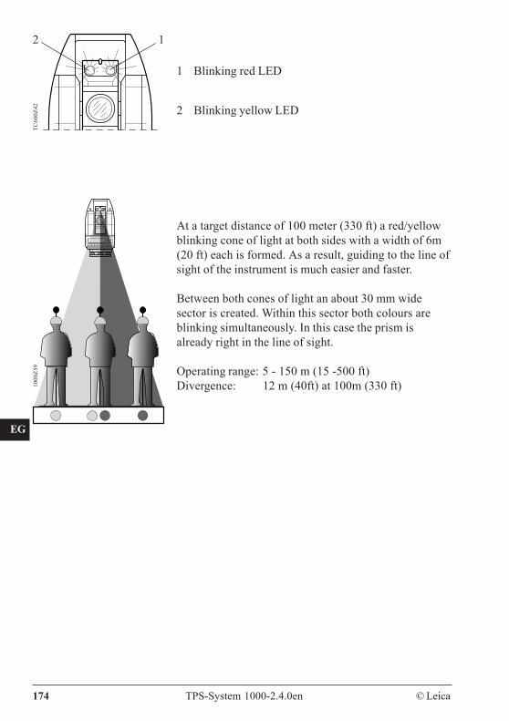
CO
IN
ID
PM
FS
SC
OC
IO
AR
RC
EG
CA
CT
BC
DF
SD
TS
IX
174 TPS-System 1000-2.4.0en © Leica
TC60
0Z42
2 1
1 Blinking red LED
2 Blinking yellow LED
1000
Z59
At a target distance of 100 meter (330 ft) a red/yellowblinking cone of light at both sides with a width of 6m(20 ft) each is formed. As a result, guiding to the line ofsight of the instrument is much easier and faster.
Between both cones of light an about 30 mm widesector is created. Within this sector both colours areblinking simultaneously. In this case the prism isalready right in the line of sight.
Operating range: 5 - 150 m (15 -500 ft)Divergence: 12 m (40ft) at 100m (330 ft)
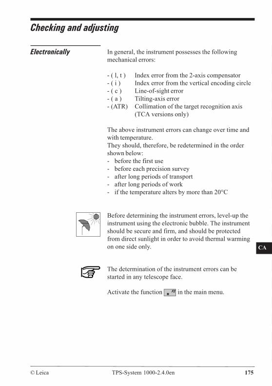
CO
IN
ID
PM
FS
SC
OC
IO
AR
RC
EG
CA
CT
BC
DF
SD
TS
IX
© Leica TPS-System 1000-2.4.0en 175
Checking and adjusting
Electronically In general, the instrument possesses the followingmechanical errors:
- ( l, t ) Index error from the 2-axis compensator- ( i ) Index error from the vertical encoding circle- ( c ) Line-of-sight error- ( a ) Tilting-axis error- (ATR) Collimation of the target recognition axis
(TCA versions only)
The above instrument errors can change over time andwith temperature.They should, therefore, be redetermined in the ordershown below:- before the first use- before each precision survey- after long periods of transport- after long periods of work- if the temperature alters by more than 20°C
Before determining the instrument errors, level-up theinstrument using the electronic bubble. The instrumentshould be secure and firm, and should be protectedfrom direct sunlight in order to avoid thermal warmingon one side only.
The determination of the instrument errors can bestarted in any telescope face.
Activate the function in the main menu.
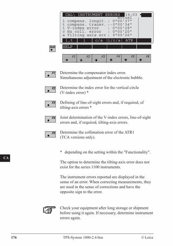
CO
IN
ID
PM
FS
SC
OC
IO
AR
RC
EG
CA
CT
BC
DF
SD
TS
IX
176 TPS-System 1000-2.4.0en © Leica
Determine the compensator index error.Simultaneous adjustment of the electronic bubble.
Determine the index error for the vertical circle(V-index error) *
Defining of line-of-sight errors and, if required, oftilting-axis errors *
Joint determination of the V-index errors, line-of-sighterrors and, if required, tilting-axis errors.
Determine the collimation error of the ATR1(TCA versions only).
* depending on the setting within the "Functionality".
The option to determine the tilting-axis error does notexist for the series 1100 instruments.
The instrument errors reported are displayed in thesense of an error. When correcting measurements, theyare used in the sense of corrections and have theopposite sign to the error.
Check your equipment after long storage or shipmentbefore using it again. If necessary, determine instrumenterrors again.
F1 F2 F3 F4 F5 F6
CAL\ INSTRUMENT ERRORS 14:03
l,t i c/a i/c/a ATR
HELP
actuall compens. longit. : 0°00'37"t compens. transv. :-0°00'34"i V-index error : 0°00'28"c Hz coll. error : 0°00'20"a Tilting axis err : 0°00'26"
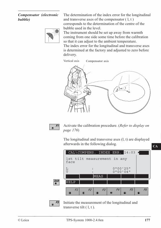
CO
IN
ID
PM
FS
SC
OC
IO
AR
RC
EG
CA
CT
BC
DF
SD
TS
IX
© Leica TPS-System 1000-2.4.0en 177
Compensator (electronicbubble)
The determination of the index error for the longitudinaland transverse axes of the compensator ( l, t )corresponds to the determination of the centre of thebubble used in the level.The instrument should be set up away from warmthcoming from one side some time before the calibrationso that it can adjust to the ambient temperature.The index error for the longitudinal and transverse axesis determined at the factory and adjusted to zero beforedelivery.
Activate the calibration procedure. (Refer to display onpage 176)
The longitudinal and transverse axes (l, t) are displayedafterwards in the following dialog.
Initiate the measurement of the longitudinal andtransverse tilt ( l, t ).
1000
Z22
tl
Compensator axisVertical axis
CAL\COMPENS. INDEX ERR. 14:03
MEAS
F1 F2 F3 F4 F5 F6
HELP
1st tilt measurement in anyface
L : 0°00'25"T : 0°00'04"
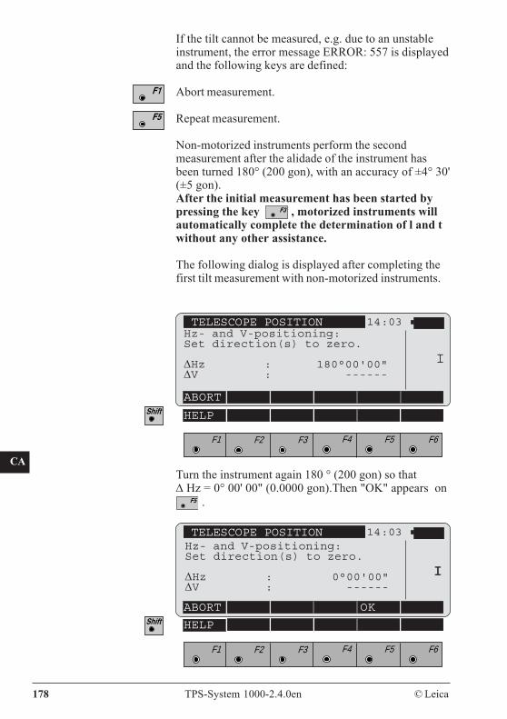
CO
IN
ID
PM
FS
SC
OC
IO
AR
RC
EG
CA
CT
BC
DF
SD
TS
IX
178 TPS-System 1000-2.4.0en © Leica
If the tilt cannot be measured, e.g. due to an unstableinstrument, the error message ERROR: 557 is displayedand the following keys are defined:
Abort measurement.
Repeat measurement.
Non-motorized instruments perform the secondmeasurement after the alidade of the instrument hasbeen turned 180° (200 gon), with an accuracy of ±4° 30'(±5 gon).After the initial measurement has been started bypressing the key , motorized instruments willautomatically complete the determination of l and twithout any other assistance.
The following dialog is displayed after completing thefirst tilt measurement with non-motorized instruments.
Turn the instrument again 180 ° (200 gon) so thatΔ Hz = 0° 00' 00" (0.0000 gon).Then "OK" appears on
.
TELESCOPE POSITION 14:03Hz- and V-positioning:Set direction(s) to zero.
ΔHz : 180°00'00"ΔV : ------
ABORT
I
F1 F2 F3 F4 F5 F6
HELP
TELESCOPE POSITION 14:03
ABORT OK
F1 F2 F3 F4 F5 F6
HELP
II
Hz- and V-positioning:Set direction(s) to zero.
ΔHz : 0°00'00"ΔV : ------
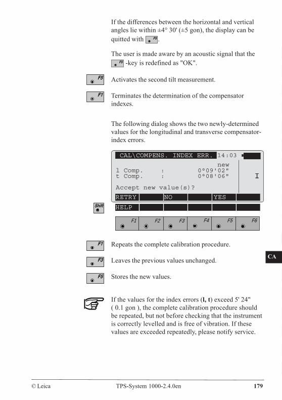
CO
IN
ID
PM
FS
SC
OC
IO
AR
RC
EG
CA
CT
BC
DF
SD
TS
IX
© Leica TPS-System 1000-2.4.0en 179
If the differences between the horizontal and verticalangles lie within ±4° 30' (±5 gon), the display can bequitted with .
The user is made aware by an acoustic signal that the -key is redefined as "OK".
Activates the second tilt measurement.
Terminates the determination of the compensatorindexes.
The following dialog shows the two newly-determinedvalues for the longitudinal and transverse compensator-index errors.
If the values for the index errors (l, t) exceed 5' 24"( 0.1 gon ), the complete calibration procedure shouldbe repeated, but not before checking that the instrumentis correctly levelled and is free of vibration. If thesevalues are exceeded repeatedly, please notify service.
Repeats the complete calibration procedure.
Leaves the previous values unchanged.
Stores the new values.
CAL\COMPENS. INDEX ERR. 14:03
RETRY NO YES
II
F1 F2 F3 F4 F5 F6
HELP
newl Comp. : 0°09'02"t Comp. : 0°08'06"
Accept new value(s)?
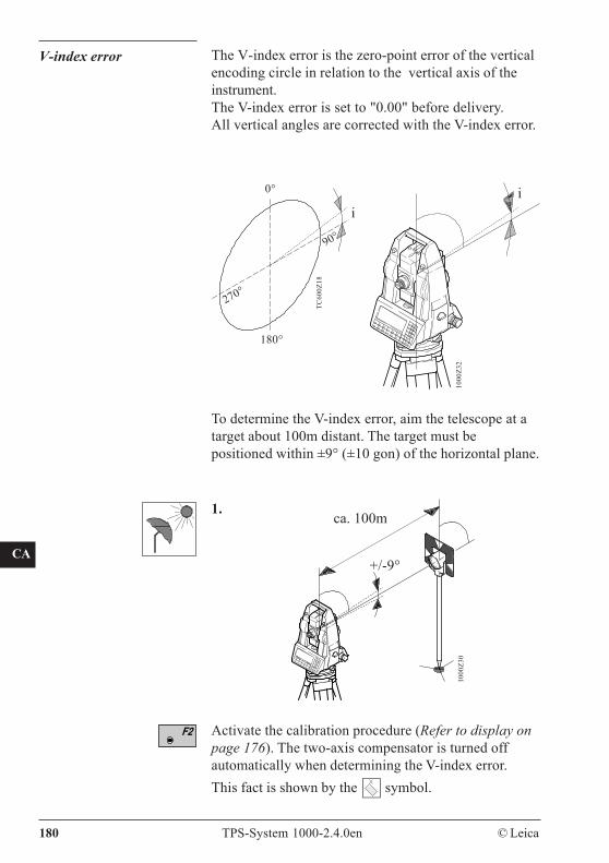
CO
IN
ID
PM
FS
SC
OC
IO
AR
RC
EG
CA
CT
BC
DF
SD
TS
IX
180 TPS-System 1000-2.4.0en © Leica
V-index error The V-index error is the zero-point error of the verticalencoding circle in relation to the vertical axis of theinstrument.The V-index error is set to "0.00" before delivery.All vertical angles are corrected with the V-index error.
i
0°
180°
270°
90°
TC60
0Z18
i
1000
Z32
To determine the V-index error, aim the telescope at atarget about 100m distant. The target must bepositioned within ±9° (±10 gon) of the horizontal plane.
Activate the calibration procedure (Refer to display onpage 176). The two-axis compensator is turned offautomatically when determining the V-index error.This fact is shown by the symbol.
ca. 100m
+/-9°
1.
1000
Z30
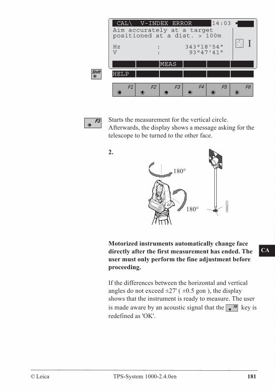
CO
IN
ID
PM
FS
SC
OC
IO
AR
RC
EG
CA
CT
BC
DF
SD
TS
IX
© Leica TPS-System 1000-2.4.0en 181
F1 F2 F3 F4 F5 F6
Starts the measurement for the vertical circle.Afterwards, the display shows a message asking for thetelescope to be turned to the other face.
2.
180°
Motorized instruments automatically change facedirectly after the first measurement has ended. Theuser must only perform the fine adjustment beforeproceeding.
If the differences between the horizontal and verticalangles do not exceed ±27' ( ±0.5 gon ), the displayshows that the instrument is ready to measure. The useris made aware by an acoustic signal that the key isredefined as 'OK'.
180°
1000
Z35
CAL\ V-INDEX ERROR 14:03
HELP
I
MEAS
Aim accurately at a targetpositioned at a dist. > 100m
Hz : 343°18'54"V : 93°47'41"
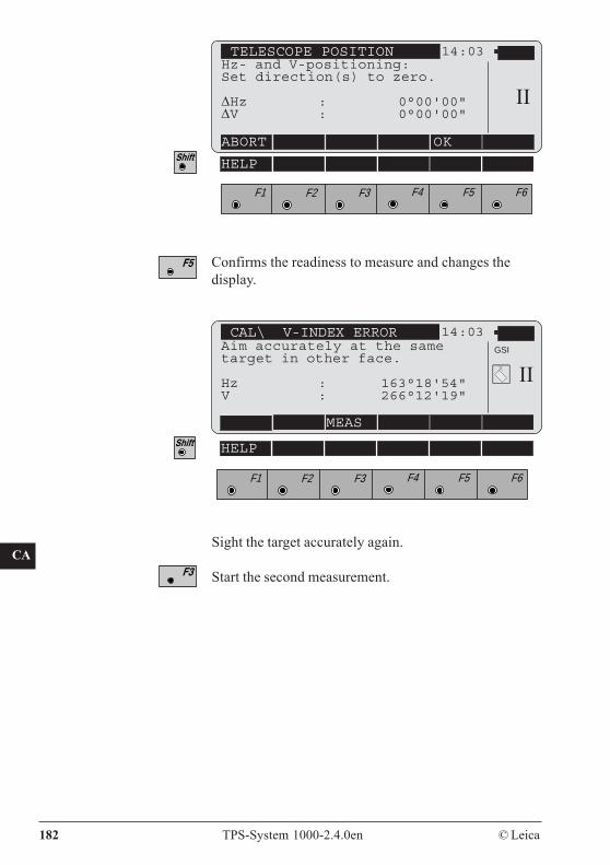
CO
IN
ID
PM
FS
SC
OC
IO
AR
RC
EG
CA
CT
BC
DF
SD
TS
IX
182 TPS-System 1000-2.4.0en © Leica
F1 F2 F3 F4 F5 F6
HELP
TELESCOPE POSITION 14:03
ABORT OK
IIHz- and V-positioning:Set direction(s) to zero.
ΔHz : 0°00'00"ΔV : 0°00'00"
Confirms the readiness to measure and changes thedisplay.
F1 F2 F3 F4 F5 F6
HELP
CAL\ V-INDEX ERROR 14:03Aim accurately at the sametarget in other face.
Hz : 163°18'54"V : 266°12'19"
MEAS
GSI
II
Sight the target accurately again.
Start the second measurement.
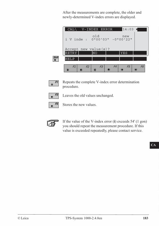
CO
IN
ID
PM
FS
SC
OC
IO
AR
RC
EG
CA
CT
BC
DF
SD
TS
IX
© Leica TPS-System 1000-2.4.0en 183
After the measurements are complete, the older andnewly-determined V-index errors are displayed.
F1 F2 F3 F4 F5 F6
HELP
CAL\ V-INDEX ERROR 14:03
old newi V inde : 0°00'03" -0°00'22"
Accept new value(s)?RETRY NO YES
Repeats the complete V-index error determinationprocedure.
Leaves the old values unchanged.
Stores the new values.
If the value of the V-index error (i) exceeds 54' (1 gon)you should repeat the measurement procedure. If thisvalue is exceeded repeatedly, please contact service.
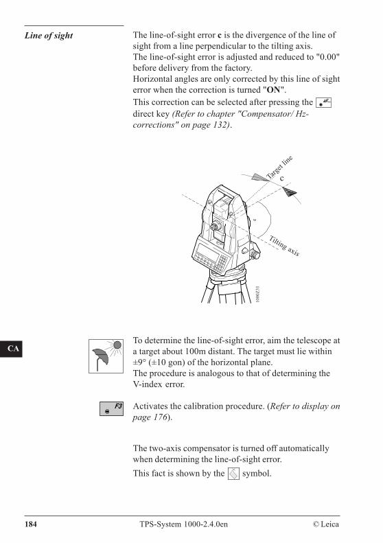
CO
IN
ID
PM
FS
SC
OC
IO
AR
RC
EG
CA
CT
BC
DF
SD
TS
IX
184 TPS-System 1000-2.4.0en © Leica
Line of sight The line-of-sight error c is the divergence of the line ofsight from a line perpendicular to the tilting axis.The line-of-sight error is adjusted and reduced to "0.00"before delivery from the factory.Horizontal angles are only corrected by this line of sighterror when the correction is turned "ON".This correction can be selected after pressing the aF...
direct key (Refer to chapter "Compensator/ Hz-corrections" on page 132).
To determine the line-of-sight error, aim the telescope ata target about 100m distant. The target must lie within±9° (±10 gon) of the horizontal plane.The procedure is analogous to that of determining theV-index error.
Activates the calibration procedure. (Refer to display onpage 176).
1000
Z31
cTarget
line
Tilting axis
The two-axis compensator is turned off automaticallywhen determining the line-of-sight error.This fact is shown by the symbol.
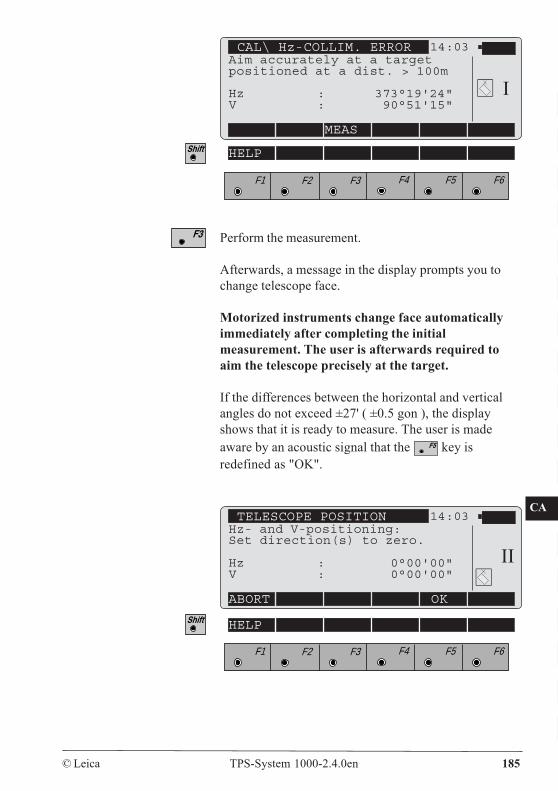
CO
IN
ID
PM
FS
SC
OC
IO
AR
RC
EG
CA
CT
BC
DF
SD
TS
IX
© Leica TPS-System 1000-2.4.0en 185
F1 F2 F3 F4 F5 F6
HELP
Perform the measurement.
Afterwards, a message in the display prompts you tochange telescope face.
Motorized instruments change face automaticallyimmediately after completing the initialmeasurement. The user is afterwards required toaim the telescope precisely at the target.
If the differences between the horizontal and verticalangles do not exceed ±27' ( ±0.5 gon ), the displayshows that it is ready to measure. The user is madeaware by an acoustic signal that the key isredefined as "OK".
F1 F2 F3 F4 F5 F6
HELP
CAL\ Hz-COLLIM. ERROR 14:03Aim accurately at a targetpositioned at a dist. > 100m
Hz : 373°19'24"V : 90°51'15"
MEAS
I
TELESCOPE POSITION 14:03Hz- and V-positioning:Set direction(s) to zero.
Hz : 0°00'00"V : 0°00'00"
ABORT OK
II
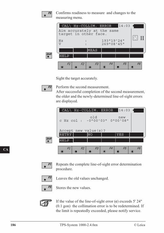
CO
IN
ID
PM
FS
SC
OC
IO
AR
RC
EG
CA
CT
BC
DF
SD
TS
IX
186 TPS-System 1000-2.4.0en © Leica
CAL\ Hz-COLLIM. ERROR 14:03
MEAS
F1 F2 F3 F4 F5 F6
HELP
Confirms readiness to measure and changes to themeasuring menu.
Sight the target accurately.
Perform the second measurement.After successful completion of the second measurement,the older and the newly-determined line-of-sight errorsare displayed.
CAL\ Hz-COLLIM. ERROR 14:03
old newc Hz col : -0°00'03" 0°00'08"
Accept new value(s)?RETRY NO YES
Repeats the complete line-of-sight error determinationprocedure.
Leaves the old values unchanged.
Stores the new values.
F1 F2 F3 F4 F5 F6
HELP
II
If the value of the line-of-sight error (c) exceeds 5' 24"(0.1 gon) the collimation error is to be redetermined. Ifthe limit is repeatedly exceeded, please notify service.
Aim accurately at the sametarget in other face.
Hz : 193°19'24"V : 269°08'45"
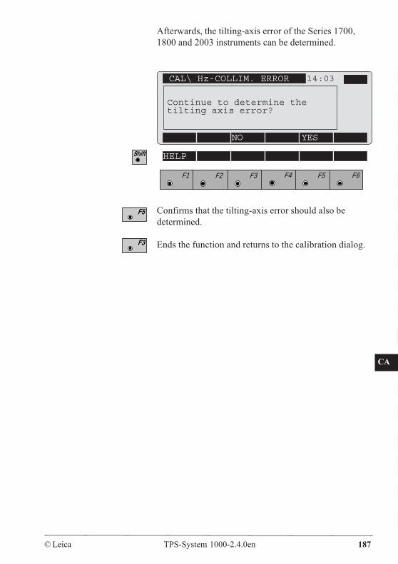
CO
IN
ID
PM
FS
SC
OC
IO
AR
RC
EG
CA
CT
BC
DF
SD
TS
IX
© Leica TPS-System 1000-2.4.0en 187
Afterwards, the tilting-axis error of the Series 1700,1800 and 2003 instruments can be determined.
F1 F2 F3 F4 F5 F6
HELP
Confirms that the tilting-axis error should also bedetermined.
Ends the function and returns to the calibration dialog.
CAL\ Hz-COLLIM. ERROR 14:03
NO YES
Continue to determine thetilting axis error?
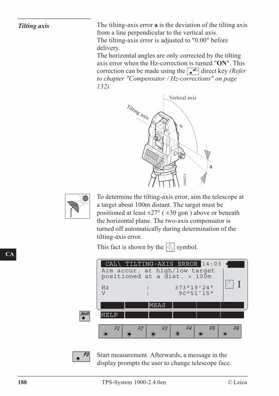
CO
IN
ID
PM
FS
SC
OC
IO
AR
RC
EG
CA
CT
BC
DF
SD
TS
IX
188 TPS-System 1000-2.4.0en © Leica
Tilting axis
To determine the tilting-axis error, aim the telescope ata target about 100m distant. The target must bepositioned at least ±27° ( ±30 gon ) above or beneaththe horizontal plane. The two-axis compensator isturned off automatically during determination of thetilting-axis error.This fact is shown by the symbol.
Start measurement. Afterwards, a message in thedisplay prompts the user to change telescope face.
The tilting-axis error a is the deviation of the tilting axisfrom a line perpendicular to the vertical axis.The tilting-axis error is adjusted to "0.00" beforedelivery.The horizontal angles are only corrected by the tiltingaxis error when the Hz-correction is turned "ON". Thiscorrection can be made using the aF... direct key (Referto chapter "Compensator / Hz-corrections" on page132).
Vertical axis
1000
Z21
a
Tilting axis
CAL\ TILTING-AXIS ERROR 14:03
MEAS
F1 F2 F3 F4 F5 F6
HELP
IAim accur. at high/low targetpositioned at a dist. > 100m
Hz : 373°19'24"V : 90°51'15"
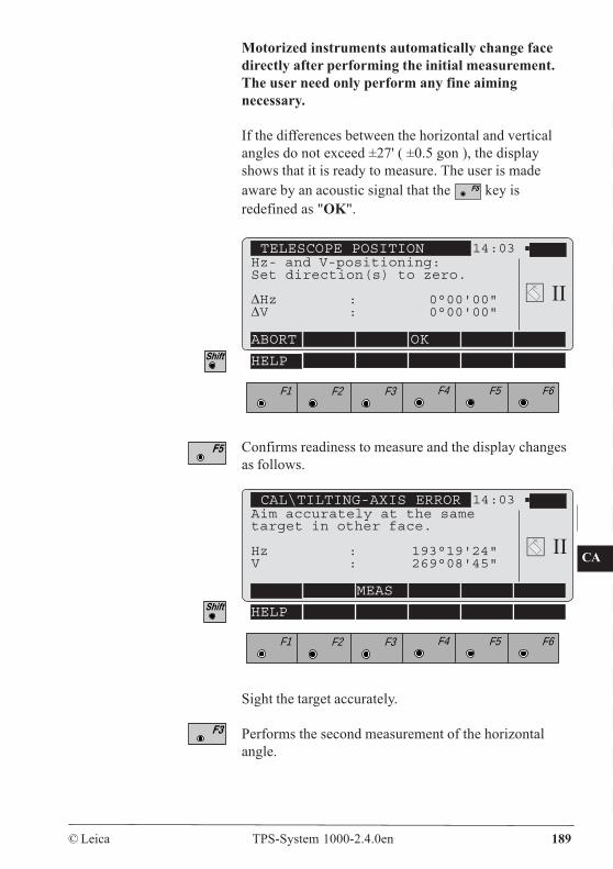
CO
IN
ID
PM
FS
SC
OC
IO
AR
RC
EG
CA
CT
BC
DF
SD
TS
IX
© Leica TPS-System 1000-2.4.0en 189
Motorized instruments automatically change facedirectly after performing the initial measurement.The user need only perform any fine aimingnecessary.
If the differences between the horizontal and verticalangles do not exceed ±27' ( ±0.5 gon ), the displayshows that it is ready to measure. The user is madeaware by an acoustic signal that the key isredefined as "OK".
TELESCOPE POSITION 14:03Hz- and V-positioning:Set direction(s) to zero.
ΔHz : 0°00'00"ΔV : 0°00'00"
ABORT OK
F1 F2 F3 F4 F5 F6
HELP
Confirms readiness to measure and the display changesas follows.
CAL\TILTING-AXIS ERROR 14:03Aim accurately at the sametarget in other face.
Hz : 193°19'24"V : 269°08'45"
MEAS
F1 F2 F3 F4 F5 F6
HELP
Sight the target accurately.
Performs the second measurement of the horizontalangle.
II
II
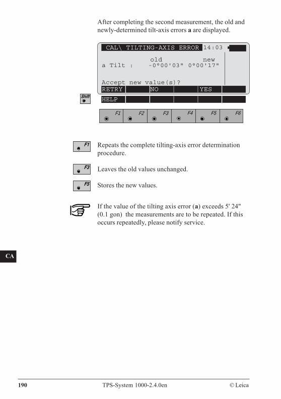
CO
IN
ID
PM
FS
SC
OC
IO
AR
RC
EG
CA
CT
BC
DF
SD
TS
IX
190 TPS-System 1000-2.4.0en © Leica
After completing the second measurement, the old andnewly-determined tilt-axis errors a are displayed.
CAL\ TILTING-AXIS ERROR 14:03
old newa Tilt : -0°00'03" 0°00'17"
Accept new value(s)?RETRY NO YES
F1 F2 F3 F4 F5 F6
HELP
If the value of the tilting axis error (a) exceeds 5' 24"(0.1 gon) the measurements are to be repeated. If thisoccurs repeatedly, please notify service.
Repeats the complete tilting-axis error determinationprocedure.
Leaves the old values unchanged.
Stores the new values.
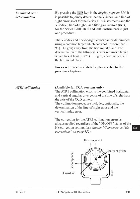
CO
IN
ID
PM
FS
SC
OC
IO
AR
RC
EG
CA
CT
BC
DF
SD
TS
IX
© Leica TPS-System 1000-2.4.0en 191
Combined errordetermination
By pressing the key in the display page on 176, itis possible to jointly determine the V-index- and line-ofsight errors (i/c) for the Series 1100 instruments and theV-index-, line-of-sight-, and tilting-axis errors (i/c/a)for the Series 1700, 1800 and 2003 instruments in justone procedure.
The V-index and line-of-sight errors can be determinedusing a common target which does not lie more than ±9° (± 10 gon) away from the horizontal plane. Thedetermination of the tilting-axis error requires a targetwhich lies at least ± 27° (± 30 gon) above or beneaththe horizontal plane.
For exact procedural details, please refer to theprevious chapters.
1000
Z19
ATR1 collimation (Available for TCA versions only)The ATR1 collimation error is the combined horizontaland vertical angular divergence of the line of sight fromthe axis of the CCD camera.The collimation procedure includes, optionally, thedetermination of the line-of-sight error and thevertical-index error.
The correction for the ATR1 collimation errors isalways applied regardless of the "ON/OFF" status of theHz-correction setting. (see chapter "Compensator / Hzcorrections" on page 132).
Centre of prism
Crosshair
V-c
ompo
nent
Hz-component
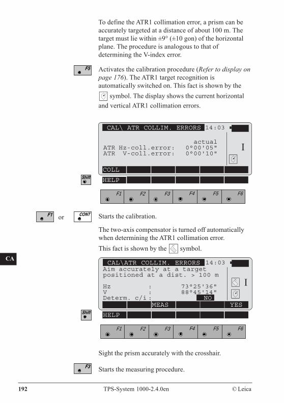
CO
IN
ID
PM
FS
SC
OC
IO
AR
RC
EG
CA
CT
BC
DF
SD
TS
IX
192 TPS-System 1000-2.4.0en © Leica
To define the ATR1 collimation error, a prism can beaccurately targeted at a distance of about 100 m. Thetarget must lie within ±9° (±10 gon) of the horizontalplane. The procedure is analogous to that ofdetermining the V-index error.
Activates the calibration procedure (Refer to display onpage 176). The ATR1 target recognition isautomatically switched on. This fact is shown by the
symbol. The display shows the current horizontaland vertical ATR1 collimation errors.
CAL\ATR COLLIM. ERRORS 14:03
MEAS YES
F1 F2 F3 F4 F5 F6
HELP
Aim accurately at a targetpositioned at a dist. > 100 m
Hz : 73°25'36"V : 88°45'14"Determ. c/i : NO
I
The two-axis compensator is turned off automaticallywhen determining the ATR1 collimation error.This fact is shown by the symbol.
or Starts the calibration.
CAL\ ATR COLLIM. ERRORS 14:03
COLL
F1 F2 F3 F4 F5 F6
HELP
IactualATR Hz-coll.error: 0°00'05"ATR V-coll.error: 0°00'10"
Sight the prism accurately with the crosshair.
Starts the measuring procedure.
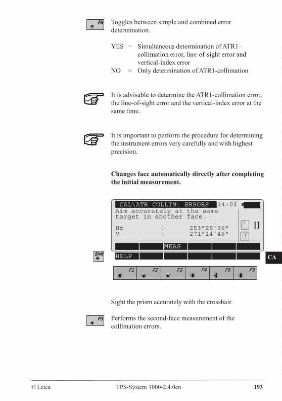
CO
IN
ID
PM
FS
SC
OC
IO
AR
RC
EG
CA
CT
BC
DF
SD
TS
IX
© Leica TPS-System 1000-2.4.0en 193
Toggles between simple and combined errordetermination.
YES = Simultaneous determination of ATR1-collimation error, line-of-sight error andvertical-index error
NO = Only determination of ATR1-collimation
It is advisable to determine the ATR1-collimation error,the line-of-sight error and the vertical-index error at thesame time.
It is important to perform the procedure for determiningthe instrument errors very carefully and with highestprecision.
Changes face automatically directly after completingthe initial measurement.
CAL\ATR COLLIM. ERRORS 14:03Aim accurately at the sametarget in another face.
Hz : 253°25'36"V : 271°14'46"
MEAS
F1 F2 F3 F4 F5 F6
HELP
Sight the prism accurately with the crosshair.
Performs the second-face measurement of thecollimation errors.
II
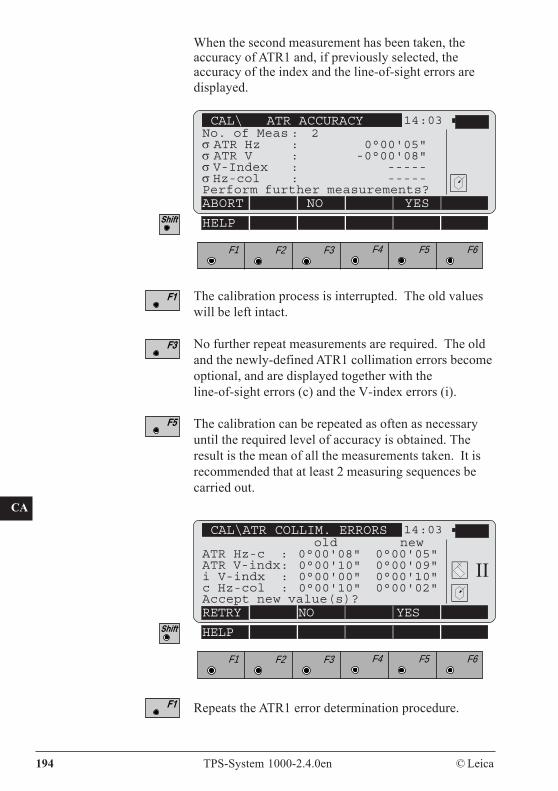
CO
IN
ID
PM
FS
SC
OC
IO
AR
RC
EG
CA
CT
BC
DF
SD
TS
IX
194 TPS-System 1000-2.4.0en © Leica
When the second measurement has been taken, theaccuracy of ATR1 and, if previously selected, theaccuracy of the index and the line-of-sight errors aredisplayed.
Repeats the ATR1 error determination procedure.
The calibration process is interrupted. The old valueswill be left intact.
No further repeat measurements are required. The oldand the newly-defined ATR1 collimation errors becomeoptional, and are displayed together with theline-of-sight errors (c) and the V-index errors (i).
The calibration can be repeated as often as necessaryuntil the required level of accuracy is obtained. Theresult is the mean of all the measurements taken. It isrecommended that at least 2 measuring sequences becarried out.
CAL\ ATR ACCURACY 14:03No. of Meas : 2σ ATR Hz : 0°00'05"σ ATR V : -0°00'08"σ V-Index : -----σ Hz-col : -----Perform further measurements?ABORT NO YES
F1 F2 F3 F4 F5 F6
HELP
CAL\ATR COLLIM. ERRORS 14:03 old new
ATR Hz-c : 0°00'08" 0°00'05"ATR V-indx: 0°00'10" 0°00'09"i V-indx : 0°00'00" 0°00'10"c Hz-col : 0°00'10" 0°00'02"Accept new value(s)?RETRY NO YES
F1 F2 F3 F4 F5 F6
HELP
II

CO
IN
ID
PM
FS
SC
OC
IO
AR
RC
EG
CA
CT
BC
DF
SD
TS
IX
© Leica TPS-System 1000-2.4.0en 195
Leaves the old values unchanged.
Stores the new values.
If the differences between the horizontal and verticalangles exceed ±27' ( ±0.5 gon ), the display gives anerror message. The user is made aware of this by anacoustic signal and the key is redefined as "OK".The measurement procedure can be repeated.
If the value of the ATR1 horizontal and verticalcollimation errors exceeds 2' 42" (0.05 gon), repeat themeasurement procedure.Similarly, if the value of the V-index error (i) exceeds54' (1 gon) or if the value of the line-of-sight error (c)exceeds 5' 24" (0.1 gon) , the measurements are to berepeated.If these values are exceeded repeatedly, please contactservice.
Tripod The connections between timber and metal must alwaysbe firm and tight.- Moderately tighten the Allen screws (2).- Tighten articulated joints (1) just enough to keep the
tripod legs open when you lift the tripod off theground.
TC60
0Z34
21
Mechanically
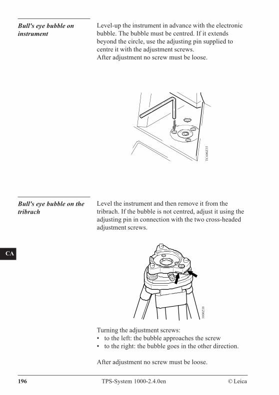
CO
IN
ID
PM
FS
SC
OC
IO
AR
RC
EG
CA
CT
BC
DF
SD
TS
IX
196 TPS-System 1000-2.4.0en © Leica
Bull's eye bubble oninstrument
Level-up the instrument in advance with the electronicbubble. The bubble must be centred. If it extendsbeyond the circle, use the adjusting pin supplied tocentre it with the adjustment screws.After adjustment no screw must be loose.
TC60
0Z35
Turning the adjustment screws:• to the left: the bubble approaches the screw• to the right: the bubble goes in the other direction.
After adjustment no screw must be loose.
Bull's eye bubble on thetribrach
Level the instrument and then remove it from thetribrach. If the bubble is not centred, adjust it using theadjusting pin in connection with the two cross-headedadjustment screws.
1000
Z18
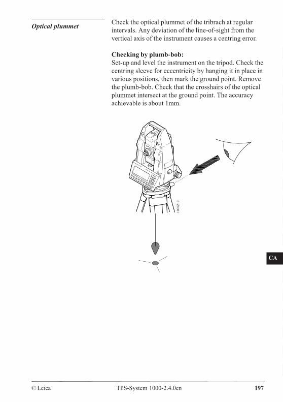
CO
IN
ID
PM
FS
SC
OC
IO
AR
RC
EG
CA
CT
BC
DF
SD
TS
IX
© Leica TPS-System 1000-2.4.0en 197
Optical plummet Check the optical plummet of the tribrach at regularintervals. Any deviation of the line-of-sight from thevertical axis of the instrument causes a centring error.
Checking by plumb-bob:Set-up and level the instrument on the tripod. Check thecentring sleeve for eccentricity by hanging it in place invarious positions, then mark the ground point. Removethe plumb-bob. Check that the crosshairs of the opticalplummet intersect at the ground point. The accuracyachievable is about 1mm.
1000
Z12
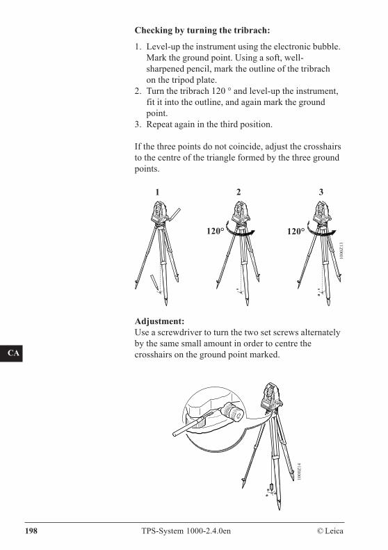
CO
IN
ID
PM
FS
SC
OC
IO
AR
RC
EG
CA
CT
BC
DF
SD
TS
IX
198 TPS-System 1000-2.4.0en © Leica
Checking by turning the tribrach:
1. Level-up the instrument using the electronic bubble.Mark the ground point. Using a soft, well-sharpened pencil, mark the outline of the tribrachon the tripod plate.
2. Turn the tribrach 120 ° and level-up the instrument,fit it into the outline, and again mark the groundpoint.
3. Repeat again in the third position.
If the three points do not coincide, adjust the crosshairsto the centre of the triangle formed by the three groundpoints.
Adjustment:Use a screwdriver to turn the two set screws alternatelyby the same small amount in order to centre thecrosshairs on the ground point marked.
21 3
120° 120°
1000
Z13
1000
Z14
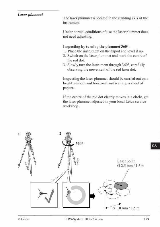
CO
IN
ID
PM
FS
SC
OC
IO
AR
RC
EG
CA
CT
BC
DF
SD
TS
IX
© Leica TPS-System 1000-2.4.0en 199
Laser plummetThe laser plummet is located in the standing axis of theinstrument.
Under normal conditions of use the laser plummet doesnot need adjusting.
Inspecting by turning the plummet 360°:1. Place the instrument on the tripod and level it up.2. Switch on the laser plummet and mark the centre of
the red dot.3. Slowly turn the instrument through 360°, carefully
observing the movement of the red laser dot.
Inspecting the laser plummet should be carried out on abright, smooth and horizonal surface (e.g. a sheet ofpaper).
If the centre of the red dot clearly moves in a circle, getthe laser plummet adjusted in your local Leica serviceworkshop.
360°
1000
Z40
≤ 1.0 mm / 1.5 m
1 2
Laser point:Ø 2.5 mm / 1.5 m
CO
IN
ID
PM
FS
SC
OC
IO
AR
RC
EG
CA
CT
BC
DF
SD
TS
IX
200 TPS-System 1000-2.4.0en © Leica
Depending on brightness and surface the size of thelaser point can vary. At a distance of 1.5 m an averagevalue of 2.5 mm diameter must be estimated.
The max. diameter of the circular movement of thecentre of the laser point should not exceed 1 mm at adistance of 1.5 m.
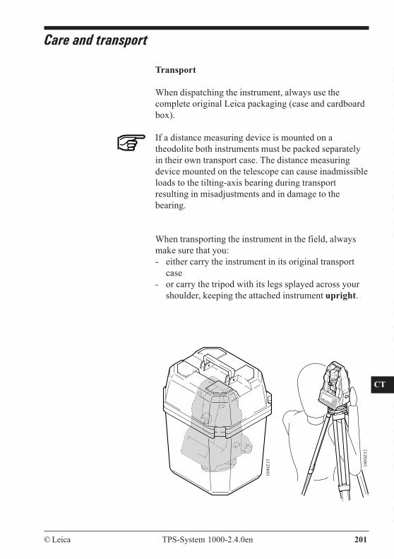
CO
IN
ID
PM
FS
SC
OC
IO
AR
RC
EG
CA
CT
BC
DF
SD
TS
IX
© Leica TPS-System 1000-2.4.0en 201
Care and transport
Transport
When dispatching the instrument, always use thecomplete original Leica packaging (case and cardboardbox).
If a distance measuring device is mounted on atheodolite both instruments must be packed separatelyin their own transport case. The distance measuringdevice mounted on the telescope can cause inadmissibleloads to the tilting-axis bearing during transportresulting in misadjustments and in damage to thebearing.
When transporting the instrument in the field, alwaysmake sure that you:- either carry the instrument in its original transport
case- or carry the tripod with its legs splayed across your
shoulder, keeping the attached instrument upright.
1000
Z32
1000
Z15
CO
IN
ID
PM
FS
SC
OC
IO
AR
RC
EG
CA
CT
BC
DF
SD
TS
IX
202 TPS-System 1000-2.4.0en © Leica
Cleaning and drying
Objective, eyepiece and prisms:- Blow dust off lenses and prisms.- Never touch the glass with your fingers.- Use only a clean, soft, lint-free cloth for cleaning.
If necessary, moisten the cloth with pure alcohol.Use no other liquids; these may attack the polymercomponents.
When storing the equipment, particularly insummer and inside a vehicle, take the storagetemperature limits into account. (-40°C to +70°C / -40°F to +158°F)
PCMCIA card, cables and plugs
Keep plugs clean and dry. Blow away any dirt lodged inthe plugs of the connecting cables. Unpluggingconnecting cables or removing the PCMCIA cardduring the measurement may cause loss of data. Alwaysswitch off the instrument before removing the cables orthe PCMCIA card.
Fogging of prisms
Reflector prisms that are cooler than the ambienttemperature tend to fog. It is not enough simply to wipethem. Keep them for some time inside your jacket or inthe vehicle to allow them to adjust to the ambienttemperature.
Storage
If the instrument becomes wet, leave it unpacked. Wipedown, clean and dry the instrument (at not more than40 °C/ 108°F), transport case, foam inserts, andaccessories. Pack up the equipment only when it isperfectly dry.
CO
IN
ID
PM
FS
SC
OC
IO
AR
RC
EG
CA
CT
BC
DF
SD
TS
IX
© Leica TPS-System 1000-2.4.0en 203
Battery charging
WARNING:The battery chargers are intended for indoor use only.Use a battery charger in a dry room only, neveroutdoors. Charge batteries only at an ambienttemperature between 10°C and 30°C ( 50°F to 86°F ).We recommend a temperature of 0°C to +20°C (32°F to68°F) for storing the batteries.
Battery chargers GKL22and GKL23
Charger GKL22:The charger provides a constant current and charges aNiCd battery within 14 hours. The charging procedurestarts automatically whenever a battery is connected tothe charger and a red control lamp indicates a fullycharged battery.Charging batteries with 2 pole plug requires an adaptercable.
Fast charger GKL23:Fast charging with the GLK-23 is possible with LeicaNiCd-batteries equipped with a 5-pole plug. Fastcharging requires 1.5 to 5 hours depending on thebattery capacity.
Leica batteries with 2-pole plugs can be charged usingan adapter cable - this charging procedure will take 14hours.
Connecting 2 batteries at the same time will charge thebatteries sequentially. Batteries with fast chargingcapabilities are priority.Charging modes and status of the GKL-23 are shown bythree-colour LEDs.
For more information about use, functions and displaysrefer to the user manual of the GKL-23.
CO
IN
ID
PM
FS
SC
OC
IO
AR
RC
EG
CA
CT
BC
DF
SD
TS
IX
204 TPS-System 1000-2.4.0en © Leica
Battery chargers GKL12and GKL14
If you already own one of these battery chargers, werecommend:- the charger GKL12 for charging the total station’s
battery insert (2-pole charging plug) and the GEB70compact battery.
- For the GEB71 universal battery, use a GKL14charger.
Before you use new batteries for the first time, chargethem for 20 to 24 hours. This also applies to batteriesthat have not been used for several months. NiCdbatteries reach full capacity after two or three normalcycles each of a 14-hour charge followed by a fulldischarge
If battery performance drops noticeably, run one or twofull cycles, i.e. charge for 14 hours and then discharge ituntil the message 53 appears: "Battery almost flat.Change battery".
Leave flat batteries to charge for fourteen hours. If youdo not know a battery’s state of charge, also leave it tocharge for fourteen hours.
Set the battery charger’s voltage selector to your ACgrid voltage, 115V or 230V. Plug in the charger to thepower. The green indicator lamp should light. If it doesnot light, there is a power cut or the power cable orcharger is faulty.Connect the battery to the charger. The red chargingindicator should light. If it does not, the battery is notcharging, i.e. the battery cable is faulty or the batteryfuse has blown and should be replaced. On the GKL12,you may not have started the timer or it may havestopped at the end of the charging period.
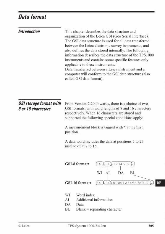
CO
IN
ID
PM
FS
SC
OC
IO
AR
RC
EG
CA
CT
BC
DF
SD
TS
IX
© Leica TPS-System 1000-2.4.0en 205
Data format
Introduction This chapter describes the data structure andorganization of the Leica GSI (Geo Serial Interface).The GSI data structure is used for all data transferredbetween the Leica electronic survey instruments, andalso defines the data stored internally. The followinginformation describes the data structure of the TPS1000instruments and contains some specific features onlyapplicable to these instruments.Data transferred between a Leica instrument and acomputer will conform to the GSI data structure (alsocalled GSI data format).
GSI storage format with8 or 16 characters
From Version 2.20 onwards, there is a choice of twoGSI formats, with word lengths of 8 and 16 charactersrespectively. When 16 characters are stored andsupported the following special conditions apply:
A measurement block is tagged with * at the firstposition.
A data word includes the data at positions 7 to 23instead of at 7 to 15.
WI Word indexAI Additional informationDA DataBL Blank = separating character
84..10+12345123
84..10+0000123456789123
GSI-8 format:
GSI-16 format:
WI AI DA BL
CO
IN
ID
PM
FS
SC
OC
IO
AR
RC
EG
CA
CT
BC
DF
SD
TS
IX
206 TPS-System 1000-2.4.0en © Leica
Block concept Data transmitted by instruments over the GSI interfaceis composed of blocks. Each one of these data blocks istreated as a whole, and ends with a terminator (CR, orCR LF). There are two types of data block:
1 Measurement blocks2 Code blocks
Measurement blocks contain a point number andmeasurement information. They are designed primarilyfor triangulation, traverse, detail, and tacheometricsurveys.Code blocks are designed primarily for recordingidentification codes, data-processing codes andinformation. However, they can also be used forrecording measurement information such as instrumentand target heights, and tie distances.
Each data block has a block number. The blocknumbers start with 1 and are incremented by 1 eachtime that a new data block is stored.
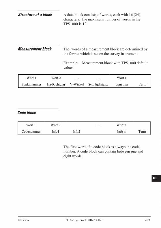
CO
IN
ID
PM
FS
SC
OC
IO
AR
RC
EG
CA
CT
BC
DF
SD
TS
IX
© Leica TPS-System 1000-2.4.0en 207
Structure of a block A data block consists of words, each with 16 (24)characters. The maximum number of words in theTPS1000 is 12.
Measurement block The words of a measurement block are determined bythe format which is set on the survey instrument.
Example: Measurement block with TPS1000 defaultvalues
Wort 1 Wort 2 ..... ..... Wort n
Punktnummer Hz-Richtung V-Winkel Schrägdistanz ppm mm Term
Code block
The first word of a code block is always the codenumber. A code block can contain between one andeight words.
Wort 1 Wort 2 ..... ..... Wort n
Codenummer Info1 Info2 Info n Term
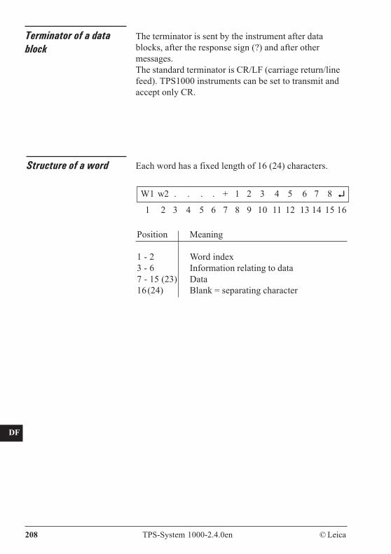
CO
IN
ID
PM
FS
SC
OC
IO
AR
RC
EG
CA
CT
BC
DF
SD
TS
IX
208 TPS-System 1000-2.4.0en © Leica
Terminator of a datablock
Structure of a word
W1 w2 . . . . + 1 2 3 4 5 6 7 8 ↵↵↵↵↵
1 2 3 4 5 6 7 8 9 10 11 12 13 14 15 16
Position Meaning
1 - 2 Word index3 - 6 Information relating to data7 - 15 (23) Data16(24) Blank = separating character
Each word has a fixed length of 16 (24) characters.
The terminator is sent by the instrument after datablocks, after the response sign (?) and after othermessages.The standard terminator is CR/LF (carriage return/linefeed). TPS1000 instruments can be set to transmit andaccept only CR.
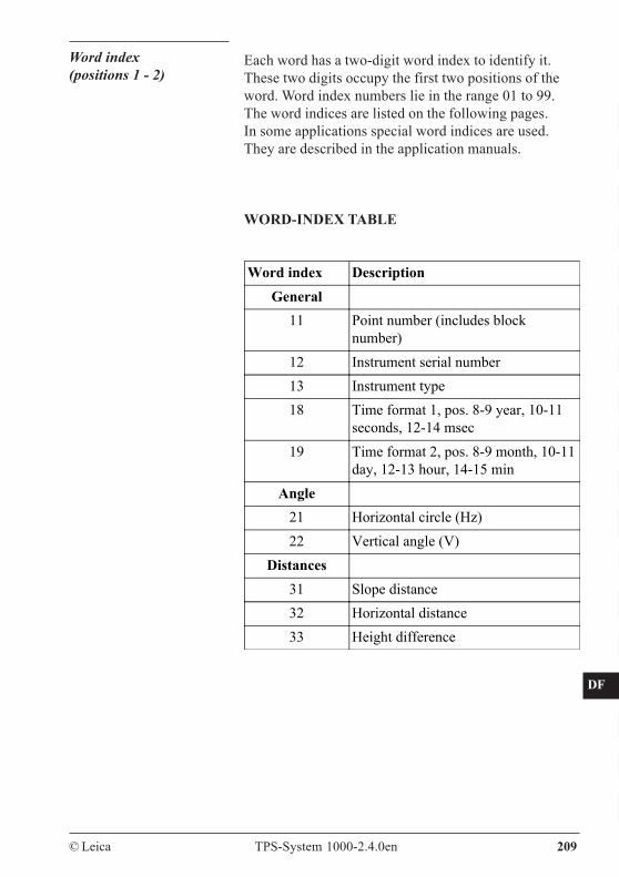
CO
IN
ID
PM
FS
SC
OC
IO
AR
RC
EG
CA
CT
BC
DF
SD
TS
IX
© Leica TPS-System 1000-2.4.0en 209
Word index(positions 1 - 2)
Each word has a two-digit word index to identify it.These two digits occupy the first two positions of theword. Word index numbers lie in the range 01 to 99.The word indices are listed on the following pages.In some applications special word indices are used.They are described in the application manuals.
WORD-INDEX TABLE
Word index DescriptionGeneral
11 Point number (includes blocknumber)
12 Instrument serial number13 Instrument type18 Time format 1, pos. 8-9 year, 10-11
seconds, 12-14 msec19 Time format 2, pos. 8-9 month, 10-11
day, 12-13 hour, 14-15 minAngle
21 Horizontal circle (Hz)22 Vertical angle (V)
Distances31 Slope distance32 Horizontal distance33 Height difference
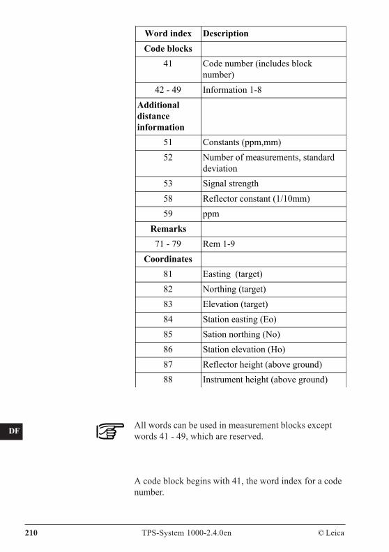
CO
IN
ID
PM
FS
SC
OC
IO
AR
RC
EG
CA
CT
BC
DF
SD
TS
IX
210 TPS-System 1000-2.4.0en © Leica
All words can be used in measurement blocks exceptwords 41 - 49, which are reserved.
A code block begins with 41, the word index for a codenumber.
Word index DescriptionCode blocks
41 Code number (includes blocknumber)
42 - 49 Information 1-8Additionaldistanceinformation
51 Constants (ppm,mm)52 Number of measurements, standard
deviation53 Signal strength58 Reflector constant (1/10mm)59 ppm
Remarks71 - 79 Rem 1-9
Coordinates81 Easting (target)82 Northing (target)83 Elevation (target)84 Station easting (Eo)85 Sation northing (No)86 Station elevation (Ho)87 Reflector height (above ground)88 Instrument height (above ground)
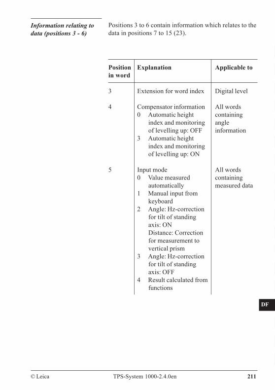
CO
IN
ID
PM
FS
SC
OC
IO
AR
RC
EG
CA
CT
BC
DF
SD
TS
IX
© Leica TPS-System 1000-2.4.0en 211
Information relating todata (positions 3 - 6)
Positions 3 to 6 contain information which relates to thedata in positions 7 to 15 (23).
Position Explanationin word
3 Extension for word index
4 Compensator information0 Automatic height
index and monitoringof levelling up: OFF
3 Automatic heightindex and monitoringof levelling up: ON
5 Input mode0 Value measured
automatically1 Manual input from
keyboard2 Angle: Hz-correction
for tilt of standingaxis: ONDistance: Correctionfor measurement tovertical prism
3 Angle: Hz-correctionfor tilt of standingaxis: OFF
4 Result calculated fromfunctions
Applicable to
Digital level
All wordscontainingangleinformation
All wordscontainingmeasured data
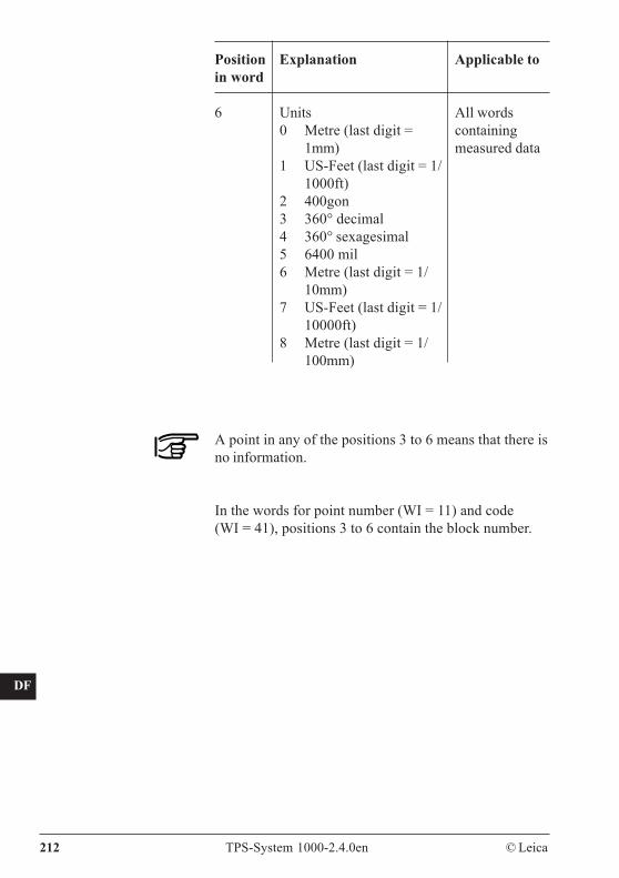
CO
IN
ID
PM
FS
SC
OC
IO
AR
RC
EG
CA
CT
BC
DF
SD
TS
IX
212 TPS-System 1000-2.4.0en © Leica
A point in any of the positions 3 to 6 means that there isno information.
In the words for point number (WI = 11) and code(WI = 41), positions 3 to 6 contain the block number.
Position Explanationin word
6 Units0 Metre (last digit =
1mm)1 US-Feet (last digit = 1/
1000ft)2 400gon3 360° decimal4 360° sexagesimal5 6400 mil6 Metre (last digit = 1/
10mm)7 US-Feet (last digit = 1/
10000ft)8 Metre (last digit = 1/
100mm)
Applicable to
All wordscontainingmeasured data
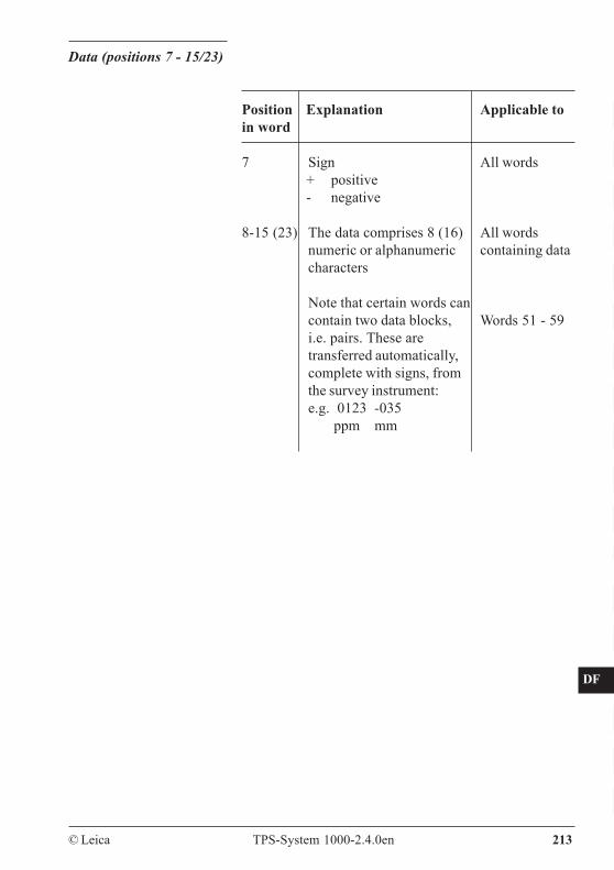
CO
IN
ID
PM
FS
SC
OC
IO
AR
RC
EG
CA
CT
BC
DF
SD
TS
IX
© Leica TPS-System 1000-2.4.0en 213
Position Explanationin word
7 Sign+ positive- negative
8-15 (23) The data comprises 8 (16)numeric or alphanumericcharacters
Note that certain words cancontain two data blocks,i.e. pairs. These aretransferred automatically,complete with signs, fromthe survey instrument:e.g. 0123 -035 ppm mm
Applicable to
All words
All wordscontaining data
Words 51 - 59
Data (positions 7 - 15/23)
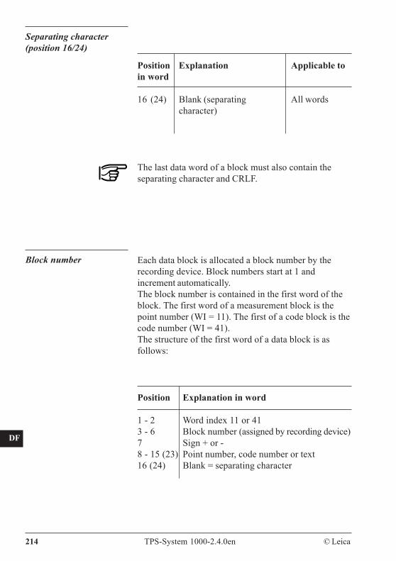
CO
IN
ID
PM
FS
SC
OC
IO
AR
RC
EG
CA
CT
BC
DF
SD
TS
IX
214 TPS-System 1000-2.4.0en © Leica
Position Explanationin word
16 (24) Blank (separatingcharacter)
Applicable to
All words
Separating character(position 16/24)
The last data word of a block must also contain theseparating character and CRLF.
Block number Each data block is allocated a block number by therecording device. Block numbers start at 1 andincrement automatically.The block number is contained in the first word of theblock. The first word of a measurement block is thepoint number (WI = 11). The first of a code block is thecode number (WI = 41).The structure of the first word of a data block is asfollows:
Position Explanation in word
1 - 2 Word index 11 or 413 - 6 Block number (assigned by recording device)7 Sign + or -8 - 15 (23) Point number, code number or text16 (24) Blank = separating character
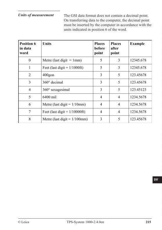
CO
IN
ID
PM
FS
SC
OC
IO
AR
RC
EG
CA
CT
BC
DF
SD
TS
IX
© Leica TPS-System 1000-2.4.0en 215
Units of measurement The GSI data format does not contain a decimal point.On transferring data to the computer, the decimal pointmust be inserted by the computer in accordance with theunits indicated in position 6 of the word.
Position 6in dataword
Units Placesbeforepoint
Placesafterpoint
Example
0 Metre (last digit = 1mm) 5 3 12345.678
1 Feet (last digit = 1/1000ft) 5 3 12345.678
2 400gon 3 5 123.45678
3 360° decimal 3 5 123.45678
4 360° sexagesimal 3 5 123.45123
5 6400 mil 4 4 1234.5678
6 Metre (last digit = 1/10mm) 4 4 1234.5678
7 Feet (last digit = 1/10000ft) 4 4 1234.5678
8 Metre (last digit = 1/100mm) 3 5 123.45678
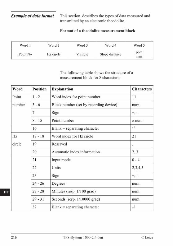
CO
IN
ID
PM
FS
SC
OC
IO
AR
RC
EG
CA
CT
BC
DF
SD
TS
IX
216 TPS-System 1000-2.4.0en © Leica
Example of data format This section describes the types of data measured andtransmitted by an electronic theodolite.
Format of a theodolite measurement block
Word Position Explanation Characters
Point 1 - 2 Word index for point number 11
number 3 - 6 Block number (set by recording device) num
7 Sign +,-
8 - 15 Point number num
16 Blank = separating character
Hz 17 - 18 Word index for Hz circle 21
circle 19 Reserved .
20 Automatic index information 2, 3
21 Input mode 0 - 4
22 Units 2,3,4,5
23 Sign +,-
24 - 26 Degrees num
27 - 28 Minutes (resp. 1/100 grad) num
29 - 31 Seconds (resp. 1/10000 grad) num
32 Blank = separating character
The following table shows the structure of ameasurement block for 8 characters:
Word 1 Word 2 Word 3 Word 4 Word 5
Point No Hz circle V circle Slope distance ppmmm
α
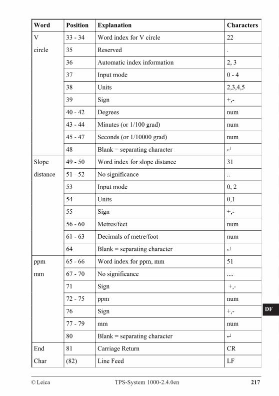
CO
IN
ID
PM
FS
SC
OC
IO
AR
RC
EG
CA
CT
BC
DF
SD
TS
IX
© Leica TPS-System 1000-2.4.0en 217
Word Position Explanation Characters
V 33 - 34 Word index for V circle 22
circle 35 Reserved .
36 Automatic index information 2, 3
37 Input mode 0 - 4
38 Units 2,3,4,5
39 Sign +,-
40 - 42 Degrees num
43 - 44 Minutes (or 1/100 grad) num
45 - 47 Seconds (or 1/10000 grad) num
48 Blank = separating character
Slope 49 - 50 Word index for slope distance 31
distance 51 - 52 No significance ..
53 Input mode 0, 2
54 Units 0,1
55 Sign +,-
56 - 60 Metres/feet num
61 - 63 Decimals of metre/foot num
64 Blank = separating character
ppm 65 - 66 Word index for ppm, mm 51
mm 67 - 70 No significance ....
71 Sign +,-
72 - 75 ppm num
76 Sign +,-
77 - 79 mm num
80 Blank = separating character
End 81 Carriage Return CR
Char (82) Line Feed LF
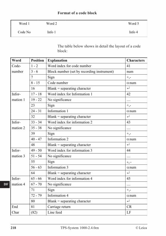
CO
IN
ID
PM
FS
SC
OC
IO
AR
RC
EG
CA
CT
BC
DF
SD
TS
IX
218 TPS-System 1000-2.4.0en © Leica
Word Position Explanation CharactersCode- 1 - 2 Word index for code number 41number 3 - 6 Block number (set by recording instrument) num
7 Sign +,-8 - 15 Code number num16 Blank = separating character
Infor- 17 - 18 Word index for Information 1 42mation 1 19 - 22 No significance ....
23 Sign +,-24 - 31 Information 1 num32 Blank = separating character
Infor- 33 - 34 Word index for information 2 43mation 2 35 - 38 No significance ....
39 Sign +,-40 - 47 Information 2 num48 Blank = separating character
Infor- 49 - 50 Word index for information 3 44mation 3 51 - 54 No significance ....
55 Sign +,−56 - 63 Information 3 num64 Blank = separating character
Infor- 65 - 66 Word index for information 4 45mation 4 67 - 70 No significance ....
71 Sign +,-72 - 79 Information 4 num80 Blank = separating character
End 81 Carriage return CRChar (82) Line feed LF
Word 1 Word 2 Word 5
Code No Info 1 Info 4
The table below shows in detail the layout of a codeblock:
Format of a code block
α
α
α
α
α
© Leica TPS-System 1000-2.4.0en 219
CO
IN
ID
PM
FS
SC
OC
IO
AR
RC
EG
CA
CT
BC
DF
SD
TS
IX
Safety directions
The following directions should enable the personresponsible for the TPS-System 1000, and the personwho actually uses the instrument, to anticipate andavoid operational hazards.The person responsible for the instrument must ensurethat all users understand these directions and adhere tothem.
Intended use ofinstrument
Permitted uses
The TPS-System 1000 electronic theodolites and totalstations are intended for the following applications:
- Measuring horizontal and vertical angles
- Measuring distances (TC-models with integrateddistance meter, T-models with removable distancemeter)
- Recording measurements
- Computing by means of application software
- Automatic target recognition (with ATR1)
- Visualizing the aiming direction (with EGL1guide light)
- Visualizing the standing axis (with the laserplummet).
- Navigating machines by determination of position(safety functions must be guaranteed by the higher machine control system).
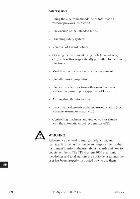
CO
IN
ID
PM
FS
SC
OC
IO
AR
RC
EG
CA
CT
BC
DF
SD
TS
IX
220 TPS-System 1000-2.4.0en © Leica
Adverse uses
- Using the electronic theodolite or total stationwithout previous instruction
- Use outside of the intended limits
- Disabling safety systems
- Removal of hazard notices
- Opening the instrument using tools (screwdriver,etc.), unless this is specifically permitted for certainfunctions
- Modification or conversion of the instrument
- Use after misappropriation
- Use with accessories from other manufacturerswithout the prior express approval of Leica
- Aiming directly into the sun
- Inadequate safeguards at the measuring station (e.g.when measuring on roads, etc.)
- Controlling machines, moving objects or similarwith the automatic target recognition ATR1.
WARNING:Adverse use can lead to injury, malfunction, anddamage. It is the task of the person responsible for theinstrument to inform the user about hazards and how tocounteract them. The TPS-System 1000 electronictheodolites and total stations are not to be used until theuser has been properly instructed how to use them.
© Leica TPS-System 1000-2.4.0en 221
CO
IN
ID
PM
FS
SC
OC
IO
AR
RC
EG
CA
CT
BC
DF
SD
TS
IX
Limits of use Environment:Suitable for use in an atmosphere appropriate forpermanent human habitation: not suitable for use inaggressive or explosive environments. Use in rain ispermissible for limited periods.
See chapter "Technical specifications".
Area of responsibility for the manufacturer of theoriginal equipment:Leica Geosystems AG, CH-9435 Heerbrugg(hereinafter referred to as Leica):Leica is responsible for supplying the product,including the user manual and original accessories, in acompletely-safe condition.
Responsibilities of the manufacturers of non-Leicaaccessories:The manufacturers of non-Leica accessories for theTPS-System 1000 electronic theodolite and totalstations are responsible for developing, implementing,and communicating safety concepts for their products,and are also responsible for the effectiveness of thosesafety concepts in combination with the Leica product.
Responsibilities of the person in charge of theinstrument:
WARNING:The person responsible for the instrument must ensurethat it is used in accordance with the instructions. Thisperson is also accountable for the training and thedeployment of personnel who use the instrument and forthe safety of the equipment in use.
The person in charge of the instrument has thefollowing duties:- To understand the safety instructions on the product
and the instructions in the user manual;- To be familiar with local regulations relating to
accident prevention;- To inform Leica immediately if the equipment
becomes unsafe.
Responsibilities
CO
IN
ID
PM
FS
SC
OC
IO
AR
RC
EG
CA
CT
BC
DF
SD
TS
IX
222 TPS-System 1000-2.4.0en © Leica
Main hazards of use
WARNING:The absence of instruction, or the inadequate impartingof instruction, can lead to incorrect or adverse use, andcan give rise to accidents with far-reaching human,material, financial, and environmental consequences.
Precautions:All users must follow the safety directions given by themanufacturer and the directions of the personresponsible for the instrument.
WARNING:The charger and the PCMCIA-card reader must not beused in damp or inclement conditions. If moisturepenetrates these devices, the user may receive anelectric shock.
Precautions:Use the charger and the PCMCIA-card reader onlyindoors, in dry rooms. Protect them from damp. If thedevices are damp, do not use them.
WARNING:If you open the charger or the PCMCIA-card reader,either of the following actions may cause you to receivean electric shock:- Touching live components;- Using the devices after incorrect attempts to carry
out repairs.
Precautions:Do not open the charger or PCMCIA-card readeryourself. Only a Leica-approved service technician isentitled to repair them.
Hazards of use
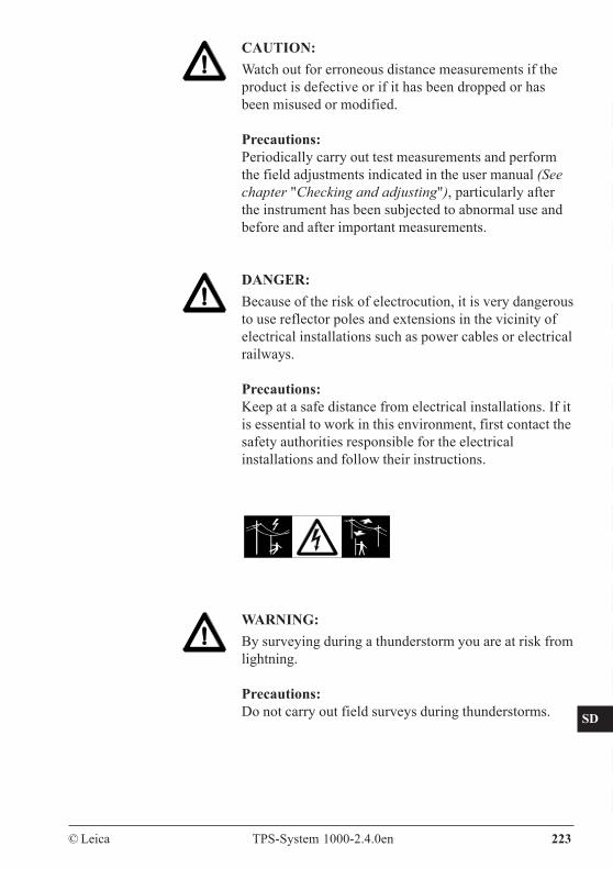
© Leica TPS-System 1000-2.4.0en 223
CO
IN
ID
PM
FS
SC
OC
IO
AR
RC
EG
CA
CT
BC
DF
SD
TS
IX
CAUTION:Watch out for erroneous distance measurements if theproduct is defective or if it has been dropped or hasbeen misused or modified.
Precautions:Periodically carry out test measurements and performthe field adjustments indicated in the user manual (Seechapter "Checking and adjusting"), particularly afterthe instrument has been subjected to abnormal use andbefore and after important measurements.
DANGER:Because of the risk of electrocution, it is very dangerousto use reflector poles and extensions in the vicinity ofelectrical installations such as power cables or electricalrailways.
Precautions:Keep at a safe distance from electrical installations. If itis essential to work in this environment, first contact thesafety authorities responsible for the electricalinstallations and follow their instructions.
WARNING:By surveying during a thunderstorm you are at risk fromlightning.
Precautions:Do not carry out field surveys during thunderstorms.
CO
IN
ID
PM
FS
SC
OC
IO
AR
RC
EG
CA
CT
BC
DF
SD
TS
IX
224 TPS-System 1000-2.4.0en © Leica
CAUTION:Be careful not to point the instrument directly towardsthe sun, because the telescope functions as a magnifyinglens and can injure your eyes or damage the internalcomponents of the EDM, ATR1 and EGL1 guide light.
Precautions:For total stations ATR1, EGL1 (TC-, TCM-, TCA-versions):Do not point the telescope directly at the sun.
For electronic theodolite (T-, TM-versions):For observations to the sun or to other highly-reflectiveobjects, use the appropriate accessories.
WARNING:During target recognition or stakeout procedures thereis a danger of accidents occurring if the user does notpay attention to the environmental conditions around orbetween the instrument and the target (e.g. obstacles,excavations or traffic).
Precautions:The person responsible for the instrument must make allusers fully aware of the existing dangers.
WARNING:When using instruments for distance measurements tomoving targets (e.g. helicopters, ships and airplanes) orto position moving objects (e.g. cranes, constructionmachines, rigs) it is possible to get incorrectmeasurements due to unforeseen events.Precautions:
© Leica TPS-System 1000-2.4.0en 225
CO
IN
ID
PM
FS
SC
OC
IO
AR
RC
EG
CA
CT
BC
DF
SD
TS
IX
Use the EDM or ATR1 only as a measuring sensor andnot as a controlling unit. Your system should be set-upand operated with appropriate safety installations (e.g.safety switch), so that no harm can occur as a result ofincorrect measurements, disturbances to the instrument,or power interruptions.
WARNING:Inadequate securing of the surveying site can lead todangerous situations, for example in traffic, on buildingsites, and at industrial installations.
Precautions:Always ensure that the survey site is adequatelysecured. Adhere to the regulations governing accidentprevention and road traffic.
CAUTION:If a target lamp accessory is used with the instrumentthe lamp's surface temperature may be extreme after along working period. It may cause pain if touched.Replacing the halogen bulb before the lamp has beenallowed to cool down may cause burning to the skin orfingers.
Precautions:Use appropriate heat protection such as gloves orwoollen cloth before touching the lamp, or allow thelamp to cool down first.
CO
IN
ID
PM
FS
SC
OC
IO
AR
RC
EG
CA
CT
BC
DF
SD
TS
IX
226 TPS-System 1000-2.4.0en © Leica
WARNING:If computers intended for use indoors are used in thefield there is a danger of electric shock.
Precautions:Adhere to the instructions given by the computermanufacturer with regard to field use in conjunctionwith Leica instruments.
CAUTION:During the transport or disposal of charged batteries itis possible for inappropriate mechanical influences toconstitute a fire hazard.
Precautions:Before transporting or disposing of equipment,discharge the battery either by running the instrument intracking mode until the batteries are exhausted ordischarging with the GKL23 battery charger.
CAUTION:If the accessories used with the instrument are notproperly secured and the equipment is subjected tomechanical shock (e.g. blows, falling), the equipmentmay be damaged or people may sustain injury.
Precautions:When setting-up the instrument, make sure that theaccessories (e.g. tripod, tribrach, removable EDM withcounterbalance, connecting cables) are correctlyadapted, fitted, secured, and locked in position. Avoidsubjecting the equipment to mechanical shock.Never position the instrument on the tripod baseplatewithout securely tightening the central fixing screw.If the screw is loosened always remove the instrumentimmediately from the tripod.

© Leica TPS-System 1000-2.4.0en 227
CO
IN
ID
PM
FS
SC
OC
IO
AR
RC
EG
CA
CT
BC
DF
SD
TS
IX
WARNING:If the product is improperly disposed of, the followingcan happen:
- If polymer parts are burnt, poisonous gases areproduced which may impair health.
- If batteries are damaged or are heated strongly, theycan explode and cause poisoning, burning, corrosionor environmental contamination.
- By disposing of the product irresponsibly youmay enable unauthorized persons to use it incontravention of the regulations, exposing them-selves and third parties to the risk of severe injuryand rendering the environment liable tocontamination.
- Improper disposal of silicone oil may causeenvironmental contamination.
Precautions:The product must not be disposed withhousehold waste.Dispose of the product appropriately inaccordance with the national regulations inforce in your country.
Always prevent access to the product by unauthorizedpersonnel.
Product specific treatment and waste managementinformation can be downloaded from the LeicaGeosystems home page at http://www.leica-geosystems.com/treatment or received from your LeicaGeosystems dealer.
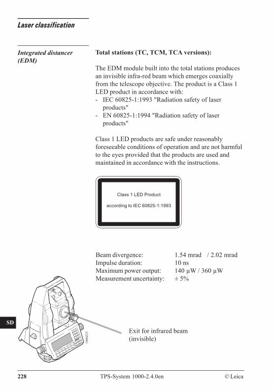
CO
IN
ID
PM
FS
SC
OC
IO
AR
RC
EG
CA
CT
BC
DF
SD
TS
IX
228 TPS-System 1000-2.4.0en © Leica
Laser classification
Integrated distancer(EDM)
Total stations (TC, TCM, TCA versions):
The EDM module built into the total stations producesan invisible infra-red beam which emerges coaxiallyfrom the telescope objective. The product is a Class 1LED product in accordance with:- IEC 60825-1:1993 "Radiation safety of laser
products"- EN 60825-1:1994 "Radiation safety of laser
products"
Class 1 LED products are safe under reasonablyforeseeable conditions of operation and are not harmfulto the eyes provided that the products are used andmaintained in accordance with the instructions.
1000
Z23 Exit for infrared beam
(invisible)
Beam divergence: 1.54 mrad / 2.02 mradImpulse duration: 10 nsMaximum power output: 140 µW / 360 µWMeasurement uncertainty: ± 5%
Class 1 LED Product
according to IEC 60825-1:1993
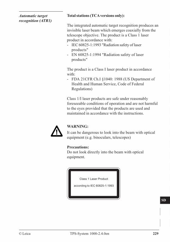
© Leica TPS-System 1000-2.4.0en 229
CO
IN
ID
PM
FS
SC
OC
IO
AR
RC
EG
CA
CT
BC
DF
SD
TS
IX
Automatic targetrecognition (ATR1)
Total stations (TCA versions only):
The integrated automatic target recognition produces aninvisible laser beam which emerges coaxially from thetelescope objective. The product is a Class 1 laserproduct in accordance with:- IEC 60825-1:1993 "Radiation safety of laser
products"- EN 60825-1:1994 "Radiation safety of laser
products"
The product is a Class I laser product in accordancewith:- FDA 21CFR Ch.I §1040: 1988 (US Department of
Health and Human Service, Code of FederalRegulations)
Class 1/I laser products are safe under reasonablyforeseeable conditions of operation and are not harmfulto the eyes provided that the products are used andmaintained in accordance with the instructions.
WARNING:It can be dangerous to look into the beam with opticalequipment (e.g. binoculars, telescopes)
Precautions:Do not look directly into the beam with opticalequipment.
Class 1 Laser Product
according to IEC 60825-1:1993
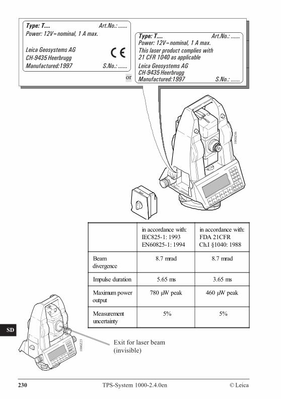
CO
IN
ID
PM
FS
SC
OC
IO
AR
RC
EG
CA
CT
BC
DF
SD
TS
IX
230 TPS-System 1000-2.4.0en © Leica
1000
Z23 Exit for laser beam
(invisible)
1000
Z46
Type: T.... Art.No.: ......Power: 12V=nominal, 1 A max.
Leica Geosystems AGCH-9435 HeerbruggManufactured:1997 S.No.: ......
or
Type: T.... Art.No.: ......Power: 12V=nominal, 1 A max.This laser product complies with21 CFR 1040 as applicableLeica Geosystems AGCH-9435 HeerbruggManufactured:1997 S.No.: ......
in accordance with:IEC825-1: 1993EN60825-1: 1994
in accordance with:FDA 21CFRCh.I §1040: 1988
Beamdivergence
8.7 mrad 8.7 mrad
Impulse duration 5.65 ms 3.65 ms
Maximum poweroutput
780 µW peak 460 µW peak
Measurementuncertainty
5% 5%
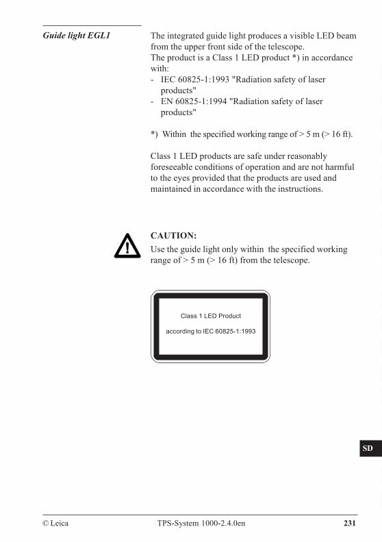
© Leica TPS-System 1000-2.4.0en 231
CO
IN
ID
PM
FS
SC
OC
IO
AR
RC
EG
CA
CT
BC
DF
SD
TS
IX
The integrated guide light produces a visible LED beamfrom the upper front side of the telescope.The product is a Class 1 LED product *) in accordancewith:- IEC 60825-1:1993 "Radiation safety of laser
products"- EN 60825-1:1994 "Radiation safety of laser
products"
*) Within the specified working range of > 5 m (> 16 ft).
Class 1 LED products are safe under reasonablyforeseeable conditions of operation and are not harmfulto the eyes provided that the products are used andmaintained in accordance with the instructions.
Guide light EGL1
CAUTION:Use the guide light only within the specified workingrange of > 5 m (> 16 ft) from the telescope.
Class 1 LED Product
according to IEC 60825-1:1993
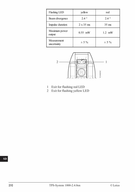
CO
IN
ID
PM
FS
SC
OC
IO
AR
RC
EG
CA
CT
BC
DF
SD
TS
IX
232 TPS-System 1000-2.4.0en © Leica
TC60
0Z42
12
1 Exit for flashing red LED2 Exit for flashing yellow LED
Flashing LED yellow red
Beam divergence 2.4 ° 2.4 °
Impulse duration 2 x 35 ms 35 ms
Maximum poweroutput 0.55 mW 1.2 mW
Measurementuncertainty ± 5 % ± 5 %
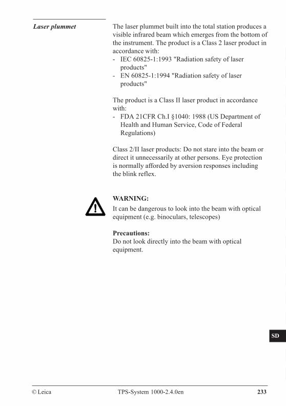
© Leica TPS-System 1000-2.4.0en 233
CO
IN
ID
PM
FS
SC
OC
IO
AR
RC
EG
CA
CT
BC
DF
SD
TS
IX
Laser plummet The laser plummet built into the total station produces avisible infrared beam which emerges from the bottom ofthe instrument. The product is a Class 2 laser product inaccordance with:- IEC 60825-1:1993 "Radiation safety of laser
products"- EN 60825-1:1994 "Radiation safety of laser
products"
The product is a Class II laser product in accordancewith:- FDA 21CFR Ch.I §1040: 1988 (US Department of
Health and Human Service, Code of FederalRegulations)
Class 2/II laser products: Do not stare into the beam ordirect it unnecessarily at other persons. Eye protectionis normally afforded by aversion responses includingthe blink reflex.
WARNING:It can be dangerous to look into the beam with opticalequipment (e.g. binoculars, telescopes)
Precautions:Do not look directly into the beam with opticalequipment.
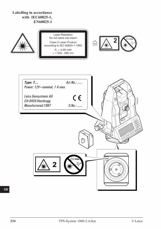
CO
IN
ID
PM
FS
SC
OC
IO
AR
RC
EG
CA
CT
BC
DF
SD
TS
IX
234 TPS-System 1000-2.4.0en © Leica
Labelling in accordancewith IEC60825-1,
EN60825-1
Type: T.... Art.No.: ......Power: 12V=nominal, 1 A max.
Leica Geosystems AGCH-9435 HeerbruggManufactured:1997 S.No.: ...... 10
00Z4
8
21/4s
Laser RadiationDo not stare into beamClass 2 Laser Product
according to IEC 60825-1:1993P0 ≤ 0.95 mW
λ = 620 - 690 nm
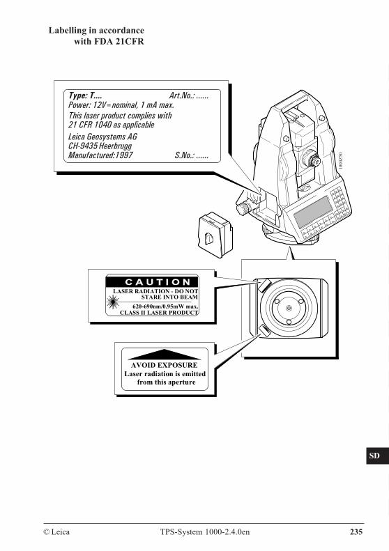
© Leica TPS-System 1000-2.4.0en 235
CO
IN
ID
PM
FS
SC
OC
IO
AR
RC
EG
CA
CT
BC
DF
SD
TS
IX
Labelling in accordancewith FDA 21CFR
1000
Z50
Type: T.... Art.No.: ......Power: 12V=nominal, 1 mA max.This laser product complies with21 CFR 1040 as applicableLeica Geosystems AGCH-9435 HeerbruggManufactured:1997 S.No.: ......
LASER RADIATION - DO NOT
620-690nm/0.95mW max.CLASS II LASER PRODUCT
STARE INTO BEAM
AVOID EXPOSURELaser radiation is emitted from this aperture
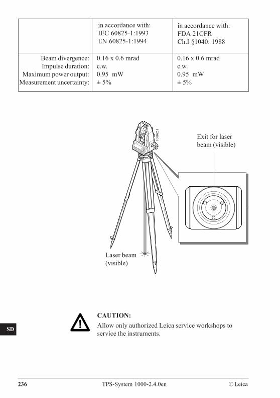
CO
IN
ID
PM
FS
SC
OC
IO
AR
RC
EG
CA
CT
BC
DF
SD
TS
IX
236 TPS-System 1000-2.4.0en © Leica
CAUTION:Allow only authorized Leica service workshops toservice the instruments.
in accordance with:IEC 60825-1:1993EN 60825-1:1994
in accordance with:FDA 21CFRCh.I §1040: 1988
1000
Z51
Laser beam(visible)
Beam divergence: 0.16 x 0.6 mrad 0.16 x 0.6 mradImpulse duration: c.w. c.w.
Maximum power output: 0.95 mW 0.95 mWMeasurement uncertainty: ± 5% ± 5%
Exit for laserbeam (visible)
© Leica TPS-System 1000-2.4.0en 237
CO
IN
ID
PM
FS
SC
OC
IO
AR
RC
EG
CA
CT
BC
DF
SD
TS
IX
The term "electromagnetic acceptability" is taken tomean the capability of the electronic theodolite or totalstation to function correctly in an environment whereelectromagnetic radiation and electrostatic dischargesare present and without causing electromagneticdisturbances in other equipment.
WARNING:Electromagnetic radiation can cause disturbances inother equipment. Although the electronic theodolitesand total stations meet the strict regulations andstandards which are in force in this respect, Leicacannot completely exclude the possibility that otherequipment may be disturbed.
CAUTION:There is a risk that disturbances may be caused in otherequipment if the electronic theodolites or total stationsare used in conjunction with accessories from othermanufacturers (e.g. field computers, personalcomputers, portable radios, non-standard cables,external batteries).
Precautions:Use the equipment only with accessories from Leica.When combined with electronic theodolites or totalstations the strict requirements stipulated by theguidelines and standards are assured. When usingcomputers and portable radios, pay attention to theinformation provided by the manufacturer regardingelectromagnetic acceptability.
Electromagneticacceptability
CO
IN
ID
PM
FS
SC
OC
IO
AR
RC
EG
CA
CT
BC
DF
SD
TS
IX
238 TPS-System 1000-2.4.0en © Leica
CAUTION:Disturbances caused by electromagnetic radiation canresult in the tolerance limits for measurements beingexceeded.Although the electronic theodolites and total stationsmeet the strict regulations and standards which are inforce in this connection, Leica cannot completelyexclude the possibility that an electronic theodolite ortotal station may be disturbed by very intenseelectromagnetic radiation, for instance near radiotransmitters, portable radios, diesel generators.Check the plausibility of results obtained under theseconditions.
WARNING:If an electronic theodolite or total station is operatedwith cables attached at only one of their two ends (e.g.external power supply cables, interface cables), thepermitted level of electromagnetic radiation may beexceeded and the correct functioning of otherinstruments may be impaired.
Precautions:While the instrument is in use, cables (e.g. instrument toexternal battery, instrument to computer) must beconnected at both ends.
WARNING:This equipment has been tested and found to complywith the limits for a Class B digital device, pursuant topart 15 of the FCC rules.These limits are designed to provide reasonableprotection against harmful interference in a residentialinstallation.
FCC statement(applicable in U.S.)
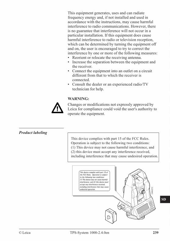
© Leica TPS-System 1000-2.4.0en 239
CO
IN
ID
PM
FS
SC
OC
IO
AR
RC
EG
CA
CT
BC
DF
SD
TS
IX
This equipment generates, uses and can radiatefrequency energy and, if not installed and used inaccordance with the instructions, may cause harmfulinterference to radio communications. However, thereis no guarantee that interference will not occur in aparticular installation. If this equipment does causeharmful interference to radio or television reception,which can be determined by turning the equipment offand on, the user is encouraged to try to correct theinterference by one or more of the following measures:• Reorient or relocate the receiving antenna.• Increase the separation between the equipment and
the receiver.• Connect the equipment into an outlet on a circuit
different from that to which the receiver isconnected.
• Consult the dealer or an experienced radio/TVtechnician for help.
WARNING:Changes or modifications not expressly approved byLeica for compliance could void the user's authority tooperate the equipment.
This device complies with part 15 of the FCC Rules.Operation is subject to the following two conditions:(1) This device may not cause harmful interference, and(2) this device must accept any interference received,including interference that may cause undesired operation.
Product labeling
This device complies with part 15 ofthe FCC Rules. Operation is subjectto the following two conditions:(1) This device may not cause harmfulinterference, and (2) this device mustaccept any interference received,including interference that may causeundesired operation.
1000
Z52

CO
IN
ID
PM
FS
SC
OC
IO
AR
RC
EG
CA
CT
BC
DF
SD
TS
IX
240 TPS-System 1000-2.4.0en © Leica
Technical specifications
Angle measurement Types Accuracy Hz, V (DIN18723)1100 3" (1 mgon)1500 2" (0.6 mgon)1700 1.5" (0.5 mgon)1800 1" (0.3 mgon)2003 0.5" (0.15 mgon)
Display (least count) 1", (0.1mgon)Type 1100 1" (0.5 mgon) Type 2003 0.1" (0.01 mgon)
Selection possibilities 360°, 400 gon, V%, 6400 milMethod absolute, continuous
Distance measurement Type: infrared
RangeAtmosphericconditions
1 Standardprism
3 Standardprisms
360°reflector
poor 1) 1200m(4000 ft)
1500m(4900ft) -----
average 2) 2500m(8200 ft)
3500m(11500ft)
1300 m(4300ft)
excellent 3) 3500 m(11500 ft)
5000m(16400ft) -----
1) Very hazy, visibility 3 km, or strong sunlight and heavyheat shimmer
2) Light haze, or some cloud and slight heat shimmer3) Overcast, no haze, visibility 30 km, no heat shimmer
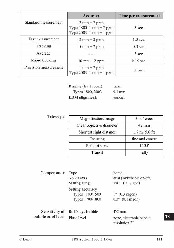
© Leica TPS-System 1000-2.4.0en 241
CO
IN
ID
PM
FS
SC
OC
IO
AR
RC
EG
CA
CT
BC
DF
SD
TS
IX
Accuracy Time per measurementStandard measurement 2 mm + 2 ppm
Type 1800 1 mm + 2 ppmType 2003 1 mm + 1 ppm
3 sec.
Fast measurement 3 mm + 2 ppm 1.5 sec.Tracking 5 mm + 2 ppm 0.3 sec.Average ----- 3 sec.
Rapid tracking 10 mm + 2 ppm 0.15 sec.Precision measurement 1 mm + 2 ppm
Type 2003 1 mm + 1 ppm 3 sec.
Display (least count): 1mmTypes 1800, 2003 0.1 mm
EDM alignment: coaxial
Magnification/Image 30x / erectClear objective diameter 42 mmShortest sight distance 1.7 m (5.6 ft)
Focusing fine and coarseField of view 1° 33'
Transit fully
Type liquidNo. of axes dual (switchable on/off)Setting range 3'47'' (0.07 gon)Setting accuracy
Types 1100/1500 1" (0.3 mgon)Types 1700/1800 0.3" (0.1 mgon)
Bull's-eye bubble 4'/2 mmPlate level none, electronic bubble
resolution 2"
Telescope
Compensator
Sensitivity ofbubble or of level
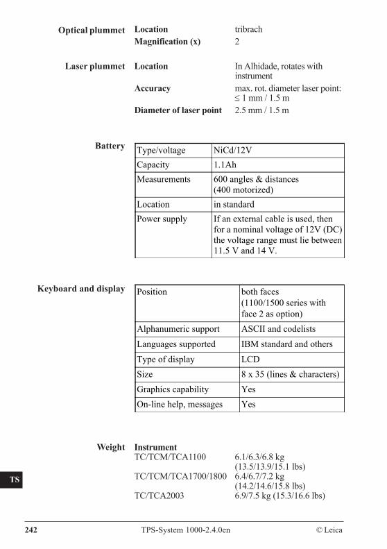
CO
IN
ID
PM
FS
SC
OC
IO
AR
RC
EG
CA
CT
BC
DF
SD
TS
IX
242 TPS-System 1000-2.4.0en © Leica
Optical plummet Location tribrachMagnification (x) 2
Location In Alhidade, rotates withinstrument
Accuracy max. rot. diameter laser point:≤ 1 mm / 1.5 m
Diameter of laser point 2.5 mm / 1.5 m
Laser plummet
Battery
Keyboard and display
Type/voltage NiCd/12VCapacity 1.1AhMeasurements 600 angles & distances
(400 motorized)Location in standardPower supply If an external cable is used, then
for a nominal voltage of 12V (DC)the voltage range must lie between11.5 V and 14 V.
Position both faces(1100/1500 series withface 2 as option)
Alphanumeric support ASCII and codelists
Languages supported IBM standard and others
Type of display LCDSize 8 x 35 (lines & characters)Graphics capability YesOn-line help, messages Yes
InstrumentTC/TCM/TCA1100 6.1/6.3/6.8 kg
(13.5/13.9/15.1 lbs)TC/TCM/TCA1700/1800 6.4/6.7/7.2 kg
(14.2/14.6/15.8 lbs)TC/TCA2003 6.9/7.5 kg (15.3/16.6 lbs)
Weight
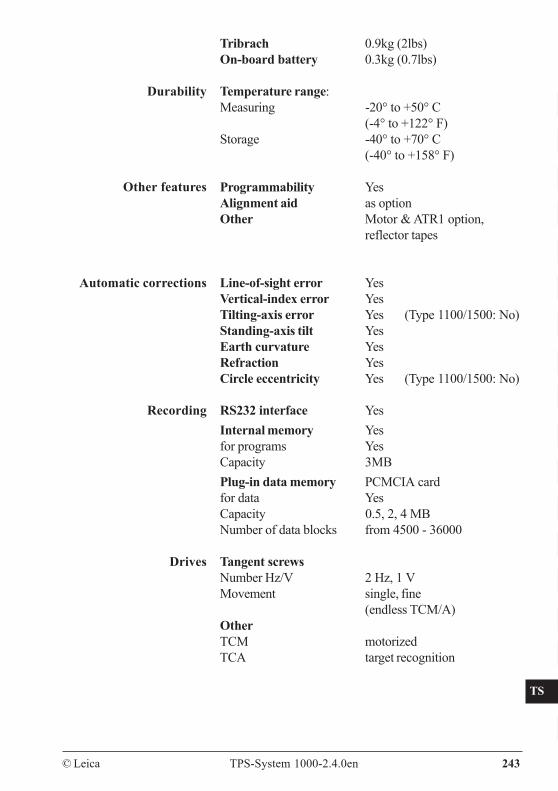
© Leica TPS-System 1000-2.4.0en 243
CO
IN
ID
PM
FS
SC
OC
IO
AR
RC
EG
CA
CT
BC
DF
SD
TS
IX
Tribrach 0.9kg (2lbs)On-board battery 0.3kg (0.7lbs)
Temperature range:Measuring -20° to +50° C
(-4° to +122° F)Storage -40° to +70° C
(-40° to +158° F)
Programmability YesAlignment aid as optionOther Motor & ATR1 option,
reflector tapes
Line-of-sight error YesVertical-index error YesTilting-axis error Yes (Type 1100/1500: No)Standing-axis tilt YesEarth curvature YesRefraction YesCircle eccentricity Yes (Type 1100/1500: No)
RS232 interface YesInternal memory Yesfor programs YesCapacity 3MBPlug-in data memory PCMCIA cardfor data YesCapacity 0.5, 2, 4 MBNumber of data blocks from 4500 - 36000
Tangent screwsNumber Hz/V 2 Hz, 1 VMovement single, fine
(endless TCM/A)OtherTCM motorizedTCA target recognition
Durability
Other features
Automatic corrections
Recording
Drives
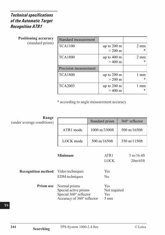
CO
IN
ID
PM
FS
SC
OC
IO
AR
RC
EG
CA
CT
BC
DF
SD
TS
IX
244 TPS-System 1000-2.4.0en © Leica
Technical specificationsof the Automatic TargetRecognition ATR1
Standard measurementTCA1100 up to 200 m
> 200 m2 mm
*TCA1800 up to 400 m
> 400 m2 mm
*Precision measurementTCA1800 up to 200 m
> 200 m1 mm
*TCA2003 up to 200 m
> 400 m1 mm
*
Standard prism 360° reflector
ATR1 mode 1000 m/3300ft 500 m/1650ft
LOCK mode 500 m/1650ft 350 m/1150ft
Positioning accuracy(standard prism)
Searching
Range(under average conditions)
* according to angle measurement accuracy
Prism use
Minimum ATR1 5 m/16.4ftLOCK 20m/65ft
Video techniques YesEDM techniques No
Normal prisms YesSpecial active prisms Not requiredSpecial 360° reflector YesAccuracy of 360° reflector 5 mm
Recognition method
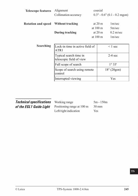
© Leica TPS-System 1000-2.4.0en 245
CO
IN
ID
PM
FS
SC
OC
IO
AR
RC
EG
CA
CT
BC
DF
SD
TS
IX
Telescope features Alignment coaxialCollimation accuracy 0.3" - 0.6" (0.1 - 0.2 mgon)
Without tracking at 20 m 1m/secat 100 m 5m/sec
During tracking at 20 m 0.2 m/secat 100 m 1m/sec
Rotation and speed
Technical specificationsof the EGL1 Guide Light
Lock-in time in active field ofATR1
< 1 sec
Typical search time intelescopic field of view
2-4 sec
Full scope of search 1° 33'Scope of search using remotecontrol
18° (20gon)
Interrupted viewing Yes
Searching
Working range 5m - 150mPositioning range at 100 m 30 mmLeft/right indication Yes
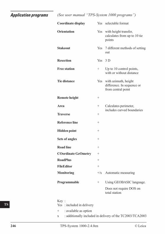
CO
IN
ID
PM
FS
SC
OC
IO
AR
RC
EG
CA
CT
BC
DF
SD
TS
IX
246 TPS-System 1000-2.4.0en © Leica
Application programs (See user manual “TPS-System 1000 programs”)
Coordinate display Yes selectable format
Orientation Yes with height transfer,calculates from up to 10 tiepoints
Stakeout Yes 7 different methods of settingout
Resection Yes 3 D
Free station + Up to 10 control points,with or without distance
Tie distance Yes with azimuth, heightdifference. In sequence orfrom central point
Remote height +
Area + Calculates perimeter,includes curved boundaries
Traverse +
Reference line +
Hidden point +
Sets of angles +
Road line +
COordinate GeOmetry +
RoadPlus +
FileEditor +
Monitoring +/x Automatic measuring
Programmable + Using GEOBASIC language.
Does not require DOS ontotal station
Key :Yes : included in delivery+ : available as optionx : additionally included in delivery of the TC2003/TCA2003
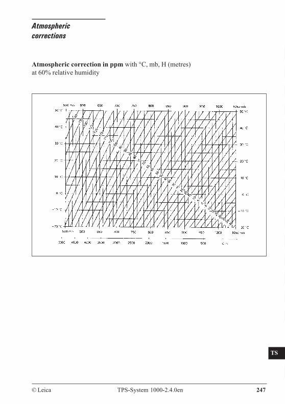
© Leica TPS-System 1000-2.4.0en 247
CO
IN
ID
PM
FS
SC
OC
IO
AR
RC
EG
CA
CT
BC
DF
SD
TS
IX
Atmosphericcorrections
Atmospheric correction in ppm with °C, mb, H (metres)at 60% relative humidity
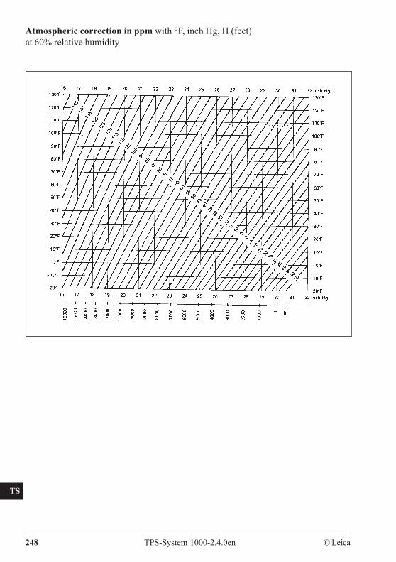
CO
IN
ID
PM
FS
SC
OC
IO
AR
RC
EG
CA
CT
BC
DF
SD
TS
IX
248 TPS-System 1000-2.4.0en © Leica
Atmospheric correction in ppm with °F, inch Hg, H (feet)at 60% relative humidity
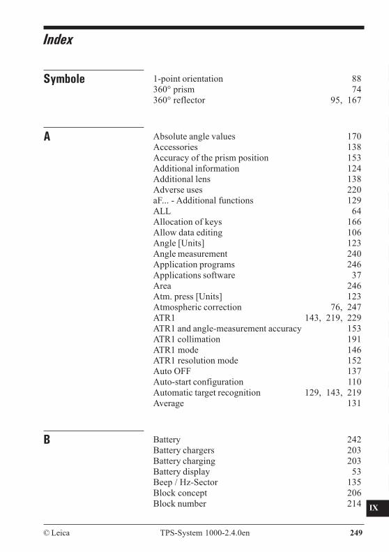
© Leica TPS-System 1000-2.4.0en 249
CO
IN
ID
PM
FS
SC
OC
IO
AR
RC
EG
CA
CT
BC
DF
SD
TS
IX
Index
Symbole 1-point orientation 88360° prism 74360° reflector 95, 167
A Absolute angle values 170Accessories 138Accuracy of the prism position 153Additional information 124Additional lens 138Adverse uses 220aF... - Additional functions 129ALL 64Allocation of keys 166Allow data editing 106Angle [Units] 123Angle measurement 240Application programs 246Applications software 37Area 246Atm. press [Units] 123Atmospheric correction 76, 247ATR1 143, 219, 229ATR1 and angle-measurement accuracy 153ATR1 collimation 191ATR1 mode 146ATR1 resolution mode 152Auto OFF 137Auto-start configuration 110Automatic target recognition 129, 143, 219Average 131
B Battery 242Battery chargers 203Battery charging 203Battery display 53Beep / Hz-Sector 135Block concept 206Block number 214
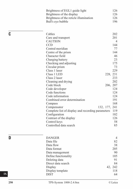
CO
IN
ID
PM
FS
SC
OC
IO
AR
RC
EG
CA
CT
BC
DF
SD
TS
IX
250 TPS-System 1000-2.4.0en © Leica
Brightness of EGL1 guide light 126Brightness of the display 126Brightness of the reticle illumination 126Bull's eye bubble 196
C Cables 202Care and transport 201CAUTION 4CCD 144Central meridian 77Centre of the prism 144Character field 46Charging battery 23Checking and adjusting 175Circular prism 73Class 1 laser 229Class 1 LED 228, 231Class 2 laser 233Cleaning and drying 202Code block 206, 207Code developer 124Code functions 124Code information 124Combined error determination 191Compass 168Compensator 132, 177, 241Complete list of display and recording parameters 119Configuration 102Contrast of the display 126Control keys 58Controlled data search 85
D DANGER 4Data file 82Data flow 38Data format 205Data management 90Define functionality 105Deleting data 91Direct data search 84Display 42, 242Display template 118DIST 64
© Leica TPS-System 1000-2.4.0en 251
CO
IN
ID
PM
FS
SC
OC
IO
AR
RC
EG
CA
CT
BC
DF
SD
TS
IX
Distance [decimal places] 122Distance [units] 122Distance corrections (ppm) 76Distance measurement 240Drives 243Durability 243
E Edit data 92EDM 33, 228EDM measuring program 131EDM selection 142EDM test 134EGL1 126, 143, 168, 171, 173, 219, 224, 231, 245Electromagnetic acceptability 237Electronic bubble 32, 128Elements of measurement 66Elev. angle % 136Elev. angle +/- 136Enable user configuration 106Enter keys 58Entering coordinates 91Eyepiece laser diode 127Eyepiece prism 138
F Face definition 123Fast measurement 131Files 130Fixed keys 57Fogging of prisms 202Follow a moving prism 148Format a memory card 100Format with 8 or 16 characters 205Free station 246Function keys 56, 166
G GEOBASIC 246GeoCOM 99Geometrical correction 75, 77Geometrical ppm 77GPH1 25, 94GPH1A 24, 73, 93
CO
IN
ID
PM
FS
SC
OC
IO
AR
RC
EG
CA
CT
BC
DF
SD
TS
IX
252 TPS-System 1000-2.4.0en © Leica
GPH1Z/GRZ3 93GRZ4 95, 167GSI command 40GSI data format 215Guide light126, 143, 168, 171, 173, 219, 224, 231, 245
H Hazards of use 222Heading 52Heatable display 127Height above the reference datum 77HELP 32Hidden point 246Hz / V 170Hz-corrections 132Hz-system 123Hz0 83
I Illumination 126Import function 84Import point data 84Important paragraphs 4Incrementing point numbers 72Index error 177Info 124Input data 39Input/output dialog 44Insert mode 48Installing a distancer 33Instrument configuration 88Instrument errors 175Instrument identification 109Integrated distancer 228Intended use of instrument 219Interface parameters (GeoCOM) 108Interface parameters (GSI) 107Interruptions to viewing 166
J Joystick 171
© Leica TPS-System 1000-2.4.0en 253
CO
IN
ID
PM
FS
SC
OC
IO
AR
RC
EG
CA
CT
BC
DF
SD
TS
IX
K Keyboard 42, 242Keystroke beep 135
L L.INT-Mode 150Language 122Laser classification 228Laser plummet 199, 233, 242Laser plummet in instrument 29Laser plummet ON/OFF 126Laser pointer 126Last point stored 172Limits of use 221Line of sight 184List field 50LOCK 167LOCK interrupt 150Lock interruption 172LOCK mode 129, 148Long distances 97Longitudinal and transverse axes (l, t) 177Longitudinal and transverse compensator-index erro179
M Main menu 62Manual distance entry 79Measurement & recording 64Measurement block 206, 207Measurement file 82Measurement frequency 134Measuring distances and angles 35Measuring distances and angles separately 68Measuring distances and angles together 67Memory concept 38Menu tree 59
N Numeric field 49
O Offset between crosshair and prism centre 144Offset correction 73, 142On-line mode 99ON/OFF 141
CO
IN
ID
PM
FS
SC
OC
IO
AR
RC
EG
CA
CT
BC
DF
SD
TS
IX
254 TPS-System 1000-2.4.0en © Leica
Operating concept 41Optical plummet 197, 242Output data 39
P Password 111, 122PCMCIA card 202, 243Placeholder 87Plugs 202Plumb-bob 197Positioning accuracy 244Power off 137ppm 76ppm values 75Precision measurement 131Preparing T- and TM - Versions 23Preparing TC, TCM and TCA - version 25Prism constant 97Prism for attachable EDM 93Prism for incorporated EDM 94Prism type 75Program-selection dialog 43Programmable 246Projection distortions 75
R Radio modems 162Range 244Rapid tracking 131REC 64Recording 243Recording station data 83Recording template 116Reduction of the range 157Refraction coefficient 75, 78Refraction correction 78Relative angle values 170Remarks 71Remote height 246Remote-control mode 101, 107Remote-Controlled Surveying 161Responsibilities 221Retro tape 74, 96Rotation and speed 245
© Leica TPS-System 1000-2.4.0en 255
CO
IN
ID
PM
FS
SC
OC
IO
AR
RC
EG
CA
CT
BC
DF
SD
TS
IX
S Safety directions 219Scale correction 77Searching 244Sector beep 135Sensitivity of bubble or level 241Set and define prisms 73Setting and entering Hz direction 83Setting up the instrument 26Show all menus and buttons 105Show full ppm definition 105Signal strength 134Sleep 137Sleep after 137Software support 5Standard measurement 131Standard recording template 117Start-up display 141Station entry/setting 82Status icons 53Storage 202Storage temperature limits 202Structure of a block 207Structure of a word 208Supplementary information entered 71System date and time 104System password 111System protection 111System software 37
T T - Version 17TARGET 70Target eccentricity 80Target functions 166Target-point data 70TARGT 64TC - Version 19TCA - Version 21TCM - Version 20Technical specifications 240Telescope 241Telescope features 245Temperature [units] 123Temperature range 243Terminator 208
CO
IN
ID
PM
FS
SC
OC
IO
AR
RC
EG
CA
CT
BC
DF
SD
TS
IX
256 TPS-System 1000-2.4.0en © Leica
The GeoCOM command 40Tie distance 246Tilting axis 188Time 52TM - Version 18Topological data 71Tracking 131Transport 201Tribrach with optical plummet 26Tribrach without optical plummet 28Tripod 195Two-value field 52
U Unfavourable atmospheric conditions 157Units of measurement 215Unpacking 22User configurations 113, 130User parameters 121User setting 82User template 122
V V-angle display 136V-index error 180Version number 103View data 92
W WARNING 4Weight 242Wild cards 87WORD-INDEX TABLE 209Workbench 37
Z Zenith angle 136

© Leica TPS-System 1000-2.4.0en 257
CO
IN
ID
PM
FS
SC
OC
IO
AR
RC
EG
CA
CT
BC
DF
SD
TS
IX
Leica Geosystems AG,Heerbrugg, Switzerland hasbeen certified as beingequipped with a qualitysystem which meets theInternational Standards ofQuality Management andQuality Systems (ISOstandard 9001) andEnvironmental ManagementSystems (ISO standard14001).
Total Quality Management-Our commitment to totalcustomer satisfaction
Ask your local Leica agent formore information about ourTQM program

Printed in Switzerland - Copyright Leica Geosystems AG,Heerbrugg, Switzerland 2006Translation of original text (667601-2.4.0de)
664901-2.4.0en
Leica Geosystems AGCH-9435 Heerbrugg
(Switzerland)Phone +41 71 727 31 31Fax +41 71 727 46 73
www.leica-geosystems.com


