ABSTRACTThe TPS65988 and TPS65987D are PD3.0 capable PD controllers. One of the most difficult features toimplement from the PD3.0 specification is the Fast Role Swap (FRS). FRS is useful particularly in thecase of a dongle connected to a laptop. Most dongles have a pass through charge function that allowsusers to connect their PD charger to the dongle and charge the laptop through the Type-C connectionfrom the dongle. In this case, the dongle is the power source and the laptop is the power sink. When theuser disconnects the PD adapter from the dongle, the laptop needs to become the power source and thedongle becomes the power sink. FRS allows this to happen without VBUS dropping to 0 V whichmaintains the data connection. In the past, PD2.0 systems would implement a regular power role swap inthese situations, which requires VBUS to drop to 0 V before the laptop can start sourcing power. Thiswould interrupt the data connection from the laptop to the dongle and create a poor user experience. FRSis supported on the TPS65988 and TPS65987D in the notebook application (FRS old sink, new source).
Contents1 Introduction ................................................................................................................... 12 Test Setup .................................................................................................................... 1
List of Figures
1 TPS65988EVM and Huawei Dongle Before an FRS ................................................................... 22 TPS65988EVM and Huawei Dongle After an FRS...................................................................... 33 FRS Oscilloscope Capture ................................................................................................. 44 FRS PD Messaging Sequence ............................................................................................ 45 Transition Diagram for Fast Role Swap .................................................................................. 5
TrademarksHuawei is a trademark of Huawei technologies Co. Ltd.All other trademarks are the property of their respective owners.
1 IntroductionFast Power Role Swap (FRS) was introduced as a protocol in USB PD 3.0. FRS allows for the powerroles of devices to change without data being interrupted. In this application report, a TPS65988EVM isused to emulate a laptop and a Huawei multiport adapter is used as the dongle. Initially, the laptop is thepower sink and the dongle is the power source. However, when power is removed from the Huawei™dongle, the power roles of the devices swap. During testing, data is constantly streamed to and from theHuawei dongle to ensure that there are no data interruptions during an FRS event.
2 Test Setup
2.1 Configuring the TPS65988EVMSettings for the TPS65988EVM should be updated to support FRS.
1. Open the TPS6598x configuration tool.2. Select an Advanced DRP Host template for the TPS65988 that does not support an external controller.3. Change the configuration settings as highlighted in Table 1 after loading that configuration.
Table 1. TPS65988EVM FRS Settings
REGISTER FIELD DEFAULT TEMPLATESETTING FRS SETTING
Port Control (0x29) Automatic Sink Cap Disabled EnabledTransmit Source
Capabilities (0x32) Number of Bank 0 Source PDOs 4 1
PD3 ConfigurationRegister (0x42) Fast Role Swap Supported Disabled Enabled
NOTE: Ensure the same settings are changed on Port 0 and Port 1 of the TPS65988EVMconfiguration file.
2.2 Initiating a Fast Role SwapComplete the following steps when setting up the EVM and dongle to complete a Fast Role Swap:1. Connect 20-V Barrel Jack Connector to TPS65988EVM.2. Connect 20-V PD Adapter to Huawei Dongle.3. Connect TPS65988EVM to Huawei Dongle through the tethered USB Type-C cable.
After these steps have been completed, the two EVMs should be setup in the same method as Figure 1.
Figure 1. TPS65988EVM and Huawei Dongle Before an FRS
You can see on the TPS65988EVM that D5 is off. D5 is the LED connected to the DC/DC supply used tosource power on Port A. This DC/DC supply is only off when the TPS65988EVM is acting as a power sink.
To initiate the Fast Role Swap, remove the PD adapter from the Huawei Dongle. This causes the dongleto trigger the Fast Role Swap PD message as the dongle is no longer able to source power. TheTPS65988EVM then monitors the voltage on VBUS and closes its source power path once the voltage onVBUS is within the VSafe5V maximum of 5.5 V as defined in the USB Type-C PD specification. Asuccessful FRS can be easily observed by monitoring the VBUS LED on either EVM. The LED never turnsoff and only dims slightly as VBUS goes from 20 V to 5 V.
Figure 2 highlights what the TPS65988EVM and Huawei Dongle looks like after the FRS has successfullycompleted.
Figure 2. TPS65988EVM and Huawei Dongle After an FRS
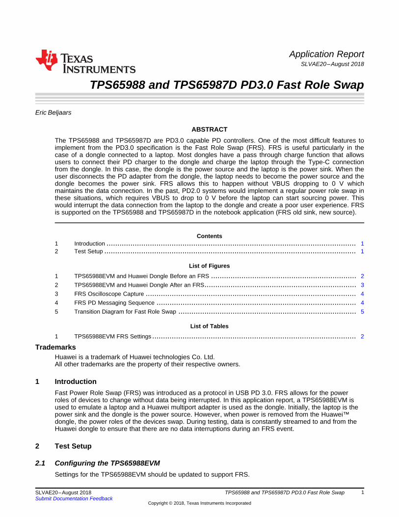
2.3 FRS messagesDuring a Fast Role Swap event, you see the VBUS voltage transfer from 20 V to 5 V. There is alsonumerous messages sent over CC to indicate a successful FRS. Figure 3 highlights an oscilloscopecapture of VBUS and CC during a successful Fast Role Swap.
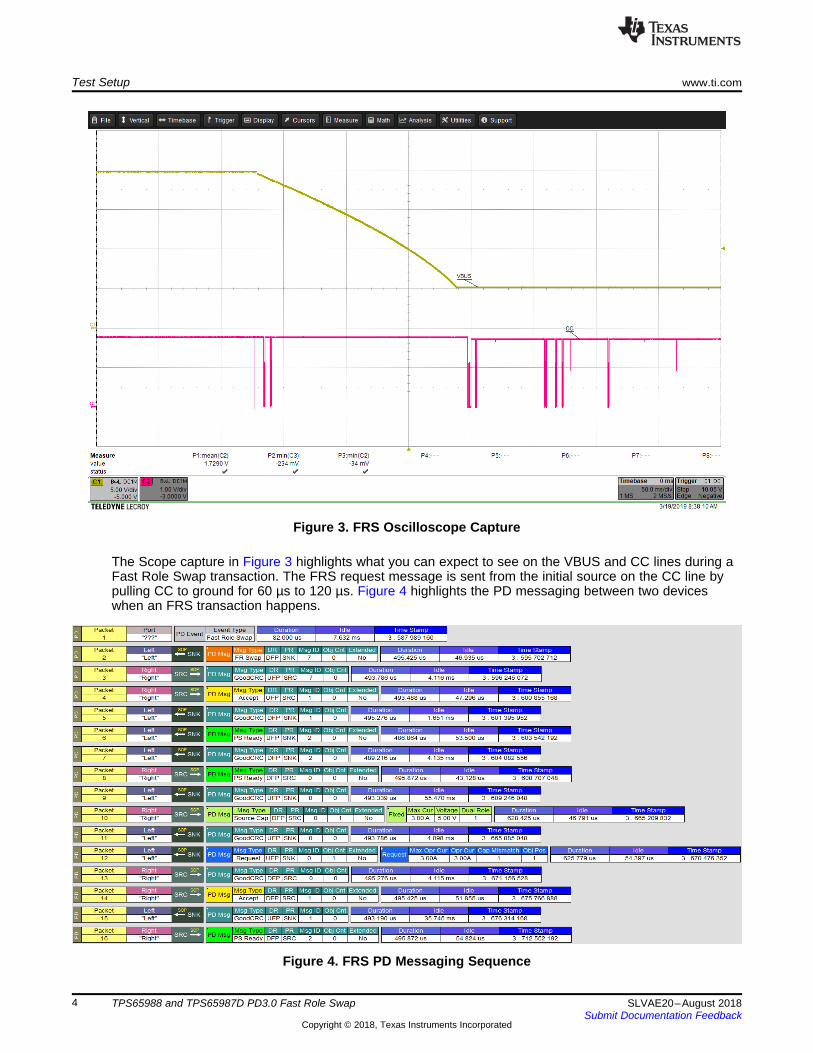
The Scope capture in Figure 3 highlights what you can expect to see on the VBUS and CC lines during aFast Role Swap transaction. The FRS request message is sent from the initial source on the CC line bypulling CC to ground for 60 µs to 120 µs. Figure 4 highlights the PD messaging between two deviceswhen an FRS transaction happens.
From the FRS PD messaging, you can see the first request message indicated in Packet 1 as the FastRole Swap PD event. This is the 60 µs to 120 µs CC pulldown from the oscilloscope capture. The nextmessage in the sequence is the "FR Swap" PD message sent from original sink device. The old sourcethen sends an accept message to the old sink and changes its Rp advertisement to Rd so that the oldsource can become the new sink. Once the CC termination on the old source new sink has changed, itsends a PS Ready message to the old sink new source. Upon receiving this message, the old sink newsource changes its CC termination from an Rd to an Rp to prepare to become the power source. After theCC termination on the new source has changed, it sends a PS Ready message to the new sink to indicatethat it is now ready to be the source. After this transaction has occurred, the new source sends its sourcecapabilities to the new sink and negotiate a PD power level. The list below highlights this sequence:1. Fast Role Swap Signal (60 µs–120 us) pulldown on CC2. FR Swap PD Message3. Accept message from Old Source to Old Sink.4. Old Sink changes Rp advertisement to Rd and sends PSReady PD message.5. Old Source changes Rd advertisement to Rp and sends PSReady PD message.6. Source capabilities from New Source to New Sink7. Regular PD Power negotiation
During the Fast Role Swap, the PD devices enters a USB Type-C current level of up to 5 V or 3 A until thenew source sends source capabilities to negotiate a new PD Contract.
Figure 5 is from the USB PD3.0 specification and highlights all of the transitions that occur during a FastRole Swap.
TI PROVIDES TECHNICAL AND RELIABILITY DATA (INCLUDING DATASHEETS), DESIGN RESOURCES (INCLUDING REFERENCEDESIGNS), APPLICATION OR OTHER DESIGN ADVICE, WEB TOOLS, SAFETY INFORMATION, AND OTHER RESOURCES “AS IS”AND WITH ALL FAULTS, AND DISCLAIMS ALL WARRANTIES, EXPRESS AND IMPLIED, INCLUDING WITHOUT LIMITATION ANYIMPLIED WARRANTIES OF MERCHANTABILITY, FITNESS FOR A PARTICULAR PURPOSE OR NON-INFRINGEMENT OF THIRDPARTY INTELLECTUAL PROPERTY RIGHTS.These resources are intended for skilled developers designing with TI products. You are solely responsible for (1) selecting the appropriateTI products for your application, (2) designing, validating and testing your application, and (3) ensuring your application meets applicablestandards, and any other safety, security, or other requirements. These resources are subject to change without notice. TI grants youpermission to use these resources only for development of an application that uses the TI products described in the resource. Otherreproduction and display of these resources is prohibited. No license is granted to any other TI intellectual property right or to any thirdparty intellectual property right. TI disclaims responsibility for, and you will fully indemnify TI and its representatives against, any claims,damages, costs, losses, and liabilities arising out of your use of these resources.TI’s products are provided subject to TI’s Terms of Sale (www.ti.com/legal/termsofsale.html) or other applicable terms available either onti.com or provided in conjunction with such TI products. TI’s provision of these resources does not expand or otherwise alter TI’s applicablewarranties or warranty disclaimers for TI products.