12
TPU250 Telephone Paging Amplifier Installation and Use Manual © 2005 Bogen Communications, Inc. All rights reserved. Specifications subject to change without notice. 54-5900-01B 0507
TPU250Telephone Paging Amplifier Installation and Use Manual
© 2005 Bogen Communications, Inc.All rights reserved.Specifications subject to change without notice.54-5900-01B 0507

NoticeEvery effort was made to ensure that the information in thisguide was complete and accurate at the time of printing.However, information is subject to change.
Important Safety InformationAlways follow these basic safety precautions when installingand using the unit:
1. Read and understand all instructions.2. Follow all warnings and instructions marked on theproduct.3. DO NOT block or cover the ventilation slots andopenings. They prevent the product from overheating. DONOT place the product in a separate enclosure or cabinet,unless proper ventilation is provided.4. Never spill liquid on the product or drop objects into theventilation slots and openings. Doing so may result inserious damage to the components.5. Repair or service must be performed by a factoryauthorized repair facility.6.The product is provided with a UL-CSA approved, 3-wireground type plug. This is a safety feature. DO NOT defeatthe safety purpose of the grounding type plug. DO NOTstaple or otherwise attach the AC power supply cord tobuilding surfaces.7. DO NOT use the product near water or in a wet ordamp place (such as a wet basement).8. DO NOT use extension cords. The product must beinstalled within 6 feet of a grounded outlet receptacle.9. DO NOT install telephone wiring during a lightningstorm.10. DO NOT install telephone jacks in a wet location unlessthe jack is specifically designed for wet locations.11. Never touch uninsulated wires or terminals, unless theline has been disconnected at the paging or controllerinterface.12. Use caution when installing or modifying paging orcontrol lines.
Applications AssistanceOur Applications Engineering Department is available toassist you from 8:30 A.M. to 6:00 P.M. and on call until 8:00P.M., Eastern Daylight Time, Monday through Friday.Call 800-999-2809, Option 2.
Domestic and International ListingsUL and CSA Listed.
2
Contents
INTRODUCTION ..........................................................................................................................4
PACKAGE CONTENTS ..............................................................................................................4
INSTALLATION..............................................................................................................................5
Mounting ............................................................................................................................5
Wall Mounting........................................................................................................................5
Rack Mounting ......................................................................................................................5
WIRING CONNECTIONS ........................................................................................................6
Input Wiring......................................................................................................................6
Tel Input ..................................................................................................................................6
Music Input ............................................................................................................................7
Microphone Input ..................................................................................................................7
Night Ringer Connections ....................................................................................................8
Bridging Inputs ......................................................................................................................8
Input Cover Replacement ....................................................................................................8
‘ Output Wiring ................................................................................................................9
Speaker Connection ..............................................................................................................9
Additional Power Amplifier ............................................................................................................10
Line-Matching Transformer WMT1A Connector ..............................................................10
Output Cover Replacement................................................................................................10
OPERATION ..................................................................................................................................11
Indicators ........................................................................................................................11
Controls ....................................................................................................................11-12
3
Introduction
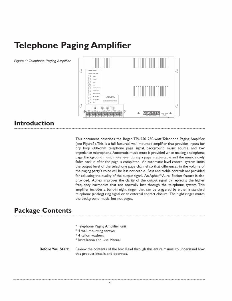
This document describes the Bogen TPU250 250-watt Telephone Paging Amplifier(see Figure1).This is a full-featured, wall-mounted amplifier that provides inputs fordry loop 600-ohm telephone page signal, background music source, and lowimpedance microphone.Automatic music mute is provided when making a telephonepage. Background music mute level during a page is adjustable and the music slowlyfades back in after the page is completed. An automatic level control system limitsthe output level of the telephone page channel so that differences in the volume ofthe paging party's voice will be less noticeable. Bass and treble controls are providedfor adjusting the quality of the output signal. An Aphex® Aural Exciter feature is alsoprovided. Aphex improves the clarity of the output signal by replacing the higherfrequency harmonics that are normally lost through the telephone system. Thisamplifier includes a built-in night ringer that can be triggered by either a standardtelephone (analog) ring signal or an external contact closure. The night ringer mutesthe background music, but not pages.
Package Contents
* Telephone Paging Amplifier unit * 4 wall-mounting screws* 4 teflon washers* Installation and Use Manual
Before You Start Review the contents of the box. Read through this entire manual to understand howthis product installs and operates.
Telephone Paging Amplifier
4
Figure 1: Telephone Paging Amplifier

PEAK LEVELPOWER
BASS
MUSIC MUTERINGER VOLUME
TREBLE
APHEX
TEL VOLUME
ALC
MIC VOLUMEMUSIC VOLUME
VOX
Figure 3: Rack Mounting the Amplifier
Installation
The amplifier is designed for wall mount applications but can also be mounted in astandard 19" rack. The TPU250 amplifier weighs 31 lb.
NOTE: The amplifier will produce heat during operation which will rise and maycause problems for temperature-sensitive equipment mounted above it. Mount theamplifier near the top of the backboard (for wall mounting) or rack (for rackmounting) so that no other equipment will be above it. If this is not possible, thenallow at least 12" between the top of the amplifier and the bottom of any equipmentpositioned above it. Also allow at least 6" between the bottom of the amplifier andany equipment below it to allow for adequate air circulation.
Wall Mounting To wall mount this unit, use the four 5/8" pan head screws with nylon washersprovided (see Figure 2). Insert the top two screws first leaving the heads protrudingabout 1/4". Lift the amplifier and place it over the 2 screws using the top keyholeslots in the flanges at the sides of the amplifier.Allow the amplifier to rest on the 2screws and then proceed to insert the bottom 2 screws into the lower keyhole slots.With all the screws in place, tighten the screws to secure the amplifier.
NOTE: Backboard must be a minimum of 3/8" thick plywood and securely mountedto the wall.
Rack Mounting The amplifier was designed to mount directly to standard 19" racks using themounting flanges as shown in Figure 3 (rack screws are not supplied). In the factoryset position, the unit will protrude from the front of the rack.This provides the bestventilation of the unit and easier access to the wiring connections.
NOTE: The unit can also be mounted partially recessed in the rack by reversing themounting flanges. Unscrew the mounting flanges (3 screws mount the flange to thecover) and install them in a flipped over orientation. This position will provideadequate ventilation and centers the weight of the unit over the rack rails.
Mounting
5
PEAK LEVELPOWER
TREBLE
BASS
APHEX
MIC VOLUMEMUSIC VOLUME
ALC
TEL VOLUME
MUSIC MUTERINGER VOLUMEVOX
Figure 2: Wall Mounting the Amplifier
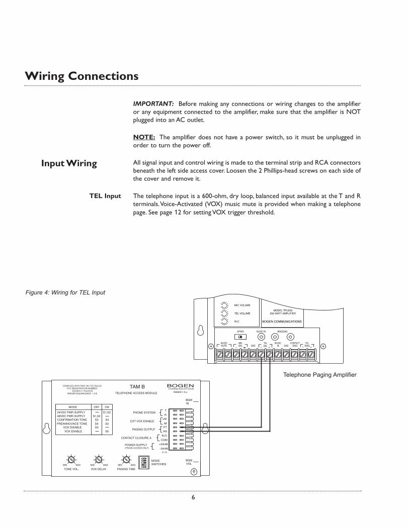
Figure 4: Wiring for TEL Input
6
Wiring Connections
IMPORTANT: Before making any connections or wiring changes to the amplifieror any equipment connected to the amplifier, make sure that the amplifier is NOTplugged into an AC outlet.
NOTE: The amplifier does not have a power switch, so it must be unplugged inorder to turn the power off.
All signal input and control wiring is made to the terminal strip and RCA connectorsbeneath the left side access cover. Loosen the 2 Phillips-head screws on each side ofthe cover and remove it.
TEL Input The telephone input is a 600-ohm, dry loop, balanced input available at the T and Rterminals.Voice-Activated (VOX) music mute is provided when making a telephonepage. See page 12 for setting VOX trigger threshold.
Input Wiring
Telephone Paging Amplifier

Music Input A single RCA connector and screw terminals are provided for the connection of abackground music source.The music input is a mono unbalanced input, so the musicsource’s output should be unbalanced and mono. If a balanced input is needed, use aBogen Line-Matching Transformer WMT1A (sold separately) to balance the musicinput.The WMT1A is also effective in breaking ground loops that cause hum.
Microphone Input A high gain, low impedance microphone input is provided in this amplifier. It isdesigned to work with microphones like Bogen’s MBS1000A microphone. Connectthe microphone's black wire to the amplifier's "-" (negative) terminal under the MICBAL connections. Connect the microphone’s Red wire to the "+" (positive) terminal.Connect the shield wire from the microphone to the adjacent GND terminal.
Two conductor shielded microphone wire should be used to extend the cable fromthe microphone. 22 AWG shielded, twisted pair speaker cable will also work.Whenextending microphone cable, be sure to connect the shields of the microphone cableto the extension wire.
Music Mute for the microphone input is not voice activated (VOX).The Music Muteterminals must be shorted to mute the music input during a microphone page.TheMBS1000A provides a contact set for this purpose.
7
Figure 5: Connect Microphone to Telephone Paging Amplifier

8
Figure 6: Bridging Inputs
Night Ringer Connection Either a standard telephone (analog) ring signal (90 - 105 V AC, 20 - 30 Hz) or anexternal contact closure activates the night ringer function of the amplifier. Toactivate the night ringer using standard telephone (analog) ring, connect the analogstation's tip lead to the TEL RING "T" terminal and connect the ring lead to the "R"terminal. If using an external contact closure, connect the closure pair across theCONTACT RING terminals (not polarized).The night ringer follows the cadence ofthe activating signal.
Bridging Inputs Bridging permits two amplifiers to be used in tandem with one another to increasethe total output power of the system, thereby permitting additional speakers to beadded (see Figure 6). For example, when two 250-watt amplifiers are bridged, thetotal output capacity of the system is 500 watts. However, bridging does not increasethe size of the load a TPU250 can individually handle. Once bridged, each amplifierwill amplify the inputs present on both amplifiers. The level control of a particularinput on an amplifier will control the volume of this signal on both amplifiers. Thecable used to bridge amplifiers should not exceed 20 feet in length.
NOTE: You cannot bridge more than two TPU250 amplifiers at one time.TPU250amplifiers can only be bridged with other TPU250 amplifiers.
Input Cover Replacement When all connections are made, remove an appropriate knockout on the inputcover. Replace the cover and tighten the screws while dressing the wires throughthe knockout hole.
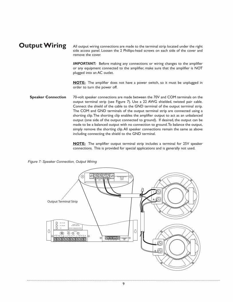
Output Wiring All output wiring connections are made to the terminal strip located under the rightside access panel. Loosen the 2 Phillips-head screws on each side of the cover andremove the cover.
IMPORTANT: Before making any connections or wiring changes to the amplifieror any equipment connected to the amplifier, make sure that the amplifier is NOTplugged into an AC outlet.
NOTE: The amplifier does not have a power switch, so it must be unplugged inorder to turn the power off.
Speaker Connection 70-volt speaker connections are made between the 70V and COM terminals on theoutput terminal strip (see Figure 7). Use a 22 AWG shielded, twisted pair cable.Connect the shield of the cable to the GND terminal of the output terminal strip.The COM and GND terminals of the output terminal strip are connected using ashorting clip.The shorting clip enables the amplifier output to act as an unbalancedoutput (one side of the output connected to ground). If desired, the output can bemade to be a balanced output with no connection to ground.To balance the output,simply remove the shorting clip.All speaker connections remain the same as aboveincluding connecting the shield to the GND terminal.
NOTE: The amplifier output terminal strip includes a terminal for 25V speakerconnections. This is provided for special applications and is generally not used.
9
Figure 7: Speaker Connection, Output Wiring
10
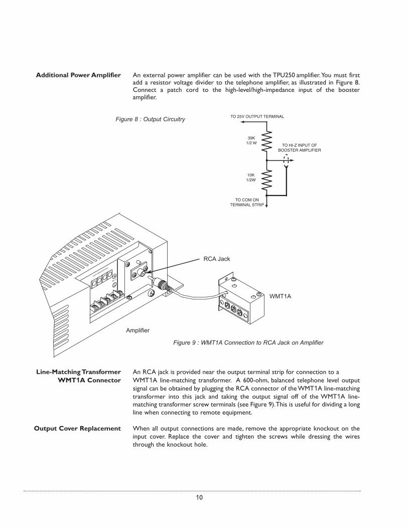
Line-Matching Transformer An RCA jack is provided near the output terminal strip for connection to aWMT1A Connector WMT1A line-matching transformer. A 600-ohm, balanced telephone level output
signal can be obtained by plugging the RCA connector of the WMT1A line-matchingtransformer into this jack and taking the output signal off of the WMT1A line-matching transformer screw terminals (see Figure 9).This is useful for dividing a longline when connecting to remote equipment.
Output Cover Replacement When all output connections are made, remove the appropriate knockout on theinput cover. Replace the cover and tighten the screws while dressing the wiresthrough the knockout hole.
.....
WMT-..A
.....
.....
.....
CLASS 2 WIRING ACCEPTABLE
Figure 9 : WMT1A Connection to RCA Jack on Amplifier
Amplifier
WMT1A
RCA Jack
Additional Power Amplifier An external power amplifier can be used with the TPU250 amplifier.You must firstadd a resistor voltage divider to the telephone amplifier, as illustrated in Figure 8.Connect a patch cord to the high-level/high-impedance input of the boosteramplifier.
TO 25V OUTPUT TERMINAL
TO HI-Z INPUT OF BOOSTER AMPLIFIER
39K 1/2 W
10K 1/2W
TO COM ON TERMINAL STRIP
Figure 8 : Output Circuitry

11
OperationIMPORTANT: Before plugging the amplifier into an AC outlet, turn all volumecontrols to their full counterclockwise positions.
POWER IND The POWER IND LED illuminates whenever AC power is applied to the amplifier(there is no power switch on the amplifier).
PEAK LEVEL The PEAK LEVEL LED illuminates whenever the speaker output signal levelapproaches its maximum level. This indicator is used when setting volume levels.Maximum output level is achieved when the PEAK LEVEL indicator flashesintermittently on loud peaks of the input signal. If the indicator illuminates steadily,the output signal volume is set too high and distortion is occurring. Decrease thevolume control for the appropriate input until the indicator flashes only occasionally.
TEL VOLUME This control adjusts the level of the telephone page output. Further adjustment canbe made using the PEAK LEVEL indicator described above.
MUSIC VOLUME This control adjusts the level of the background music output.The background musiclevel should be set to an acceptable level without overdriving the system. Whenadjusting this level, the PEAK LEVEL indicator should be observed to ensure that theamplifier signal is not distorted.
MUSIC MUTE This control adjusts the level of the background music heard during a pagingannouncement. The background music mute level should be set to the customer'ssatisfaction, but the page announcement must always be easily heard above thebackground music.
MIC VOLUME This control adjusts the level of the microphone page output.
CAUTION: Microphone should not be placed near any paging loudspeakers.
RINGER VOLUME This control adjusts the level of the night ringer tone output.The background musiclevel should be set to the customer's satisfaction. When adjusting this level, thePEAK LEVEL indicator should be used to ensure that the amplifier signal is notdistorted.
APHEX This control adjusts the amount of Aphex® Aural Exciter effect mixed in to the pagesignal. To use this function, the APHEX switch beneath the input connection covermust be set to ON. Setting this switch to OFF bypasses the Aphex effect and makesthe control inoperable.With the APHEX switch turned on, make a page and rotatethe control until the audio sounds crisp and clear.
Indicators
Controls

12
BASS and TREBLE Bass and treble controls are provided to adjust the high frequency and low frequencyresponse of the paging system. Reference positions are provided for these controls.When set to these positions, the frequency response of the system will be flat. Setthe controls to the customer’s satisfaction. Clockwise rotation increases (boosts)the response and counterclockwise reduces (cuts) the response. Increasing bassand/or treble can cause output signal peaks to increase. Check the PEAK LEVELindicator after making bass adjustment and lower the music input volume if excesspeaking occurs.
VOX (Voice Operated) SENS The VOX SENSitivity control should be set so that only the desired signal is abovethe threshold level, while noise or unwanted signal is below it.When an input signal(such as voice) is detected, the music channel will be muted.To adjust the sensitivityof this circuit:
1) Rotate the control fully clockwise.While making a page announcement and talkingat a low level, the sound should not be choppy nor missing parts of words. If it ischoppy, or if intelligibility is poor, rotate the control counterclockwise to the pointwhere the sound is clear and crisp (but not to the maximum counterclockwiseposition).
2) If the background music shuts down when no page is in progress, rotate thecontrol clockwise until the music is restored.
ALC The ALC controls the level at which the amplifier will begin to limit the output signallevel.
Manual Output Adjustment Procedure (follow only if minor adjustments to thereference settings are not adequate)
1) Disable ALC by turning ALC control to the maximum counterclockwise position.
2) Make a page, speaking softly, yet distinctly. Set the TEL VOLUME control to thedesired paging level during this page.
3) Make another page speaking relatively loudly this time. Rotate the ALC controlclockwise, while making the page, until it has the same loudness as the first page.
NOTE: The TEL Volume and ALC controls work together to set the output level.
NOTE: The PEAK LEVEL indicator should not show excessive peaking during loudpages. If this is occurring, the ALC control must be further increased.


