82
ETSI TR 101 977 V1.1.1 (2001-07) Technical Report Terrestrial Trunked Radio (TETRA); Study of the suitability of the GSM Adaptive Multi-Rate (AMR) speech codec for use in TETRA
| Date post: | 29-Mar-2018 |
| Category: |
Documents |
| Upload: | trinhtuyen |
| View: | 222 times |
| Download: | 2 times |

ETSI TR 101 977 V1.1.1 (2001-07)Technical Report
Terrestrial Trunked Radio (TETRA);Study of the suitability of the GSM
Adaptive Multi-Rate (AMR) speech codecfor use in TETRA
ETSI
ETSI TR 101 977 V1.1.1 (2001-07)2
ReferenceDTR/TETRA-05068
KeywordsCODEC, radio, TETRA, voice
ETSI
650 Route des LuciolesF-06921 Sophia Antipolis Cedex - FRANCE
Tel.: +33 4 92 94 42 00 Fax: +33 4 93 65 47 16
Siret N° 348 623 562 00017 - NAF 742 CAssociation à but non lucratif enregistrée à laSous-Préfecture de Grasse (06) N° 7803/88
Important notice
Individual copies of the present document can be downloaded from:http://www.etsi.org
The present document may be made available in more than one electronic version or in print. In any case of existing orperceived difference in contents between such versions, the reference version is the Portable Document Format (PDF).
In case of dispute, the reference shall be the printing on ETSI printers of the PDF version kept on a specific network drivewithin ETSI Secretariat.
Users of the present document should be aware that the document may be subject to revision or change of status.Information on the current status of this and other ETSI documents is available at http://www.etsi.org/tb/status/
If you find errors in the present document, send your comment to:[email protected]
Copyright Notification
No part may be reproduced except as authorized by written permission.The copyright and the foregoing restriction extend to reproduction in all media.
© European Telecommunications Standards Institute 2001.All rights reserved.

ETSI
ETSI TR 101 977 V1.1.1 (2001-07)3
Contents
Intellectual Property Rights ................................................................................................................................4
Foreword.............................................................................................................................................................4
1 Scope ........................................................................................................................................................4
2 References ................................................................................................................................................4
3 Definitions and abbreviations...................................................................................................................43.1 Definitions..........................................................................................................................................................43.2 Abbreviations .....................................................................................................................................................5
4 General .....................................................................................................................................................54.1 Work Requirements............................................................................................................................................54.2 The Tasks ...........................................................................................................................................................5
5 Initial Study of the TETRA Speech Codec ..............................................................................................65.1 TETRA Codec FEC............................................................................................................................................65.2 PSQM or Peak-PSQM For Error Sensitivity? ....................................................................................................7
6 PSQM Values for GSM AMR Codec ....................................................................................................126.1 4,75 kbit/s Mode...............................................................................................................................................126.2 5,15 kbit/s Mode...............................................................................................................................................126.3 5,9 kbit/s Mode.................................................................................................................................................126.4 6,7 kbit/s Mode.................................................................................................................................................12
7 Initial FEC Bit Allocations for GSM AMR Codec ................................................................................217.1 4,75 kbit/s Mode...............................................................................................................................................217.2 5,15 kbit/s Mode...............................................................................................................................................217.3 5,9 kbit/s Mode.................................................................................................................................................227.4 6,7 kbit/s Mode.................................................................................................................................................22
8 Coverage Performance of the FEC Schemes..........................................................................................278.1 4,75 kbit/s Mode...............................................................................................................................................278.2 5,15 kbit/s Mode...............................................................................................................................................278.3 5,9 kbit/s Mode.................................................................................................................................................278.4 6,7 kbit/s Mode.................................................................................................................................................278.5 Performance of the Selected FEC Schemes .....................................................................................................60
9 Results of expert listening tests for the TETRA and AMR codecs ........................................................779.1 4,75 kbit/s Mode...............................................................................................................................................779.2 5,15 kbit/s Mode...............................................................................................................................................779.3 5,9 kbit/s Mode.................................................................................................................................................789.4 6,7 kbit/s Mode.................................................................................................................................................78
10 Conclusions ............................................................................................................................................79
Annex A: Software Description .....................................................................................80
A.1 Soft-Bit Error Files.................................................................................................................................80
A.2 Generic 'ccoder' and 'cdecoder' Routines ...............................................................................................80
A.3 Soft-Bit Error Injection Routine.............................................................................................................80
A.4 Script Files..............................................................................................................................................81
History ..............................................................................................................................................................82
ETSI
ETSI TR 101 977 V1.1.1 (2001-07)4
Intellectual Property RightsIPRs essential or potentially essential to the present document may have been declared to ETSI. The informationpertaining to these essential IPRs, if any, is publicly available for ETSI members and non-members, and can be foundin ETSI SR 000 314: "Intellectual Property Rights (IPRs); Essential, or potentially Essential, IPRs notified to ETSI inrespect of ETSI standards", which is available from the ETSI Secretariat. Latest updates are available on the ETSI Webserver (http://www.etsi.org/ipr).
Pursuant to the ETSI IPR Policy, no investigation, including IPR searches, has been carried out by ETSI. No guaranteecan be given as to the existence of other IPRs not referenced in ETSI SR 000 314 (or the updates on the ETSI Webserver) which are, or may be, or may become, essential to the present document.
ForewordThis Technical Report (TR) has been produced by ETSI Project Terrestrial Trunked Radio (TETRA).
The present document provides the performance results of an investigation into the suitability of the GSM AdaptiveMulti-Rate (AMR) speech codec for use in TETRA.
The content of the present document is subject to continuing work within EP-TETRA and may change following formalEP-TETRA approval.
1 ScopeThe present document provides background information on the performance of four modes of the GSM AdaptiveMulti-Rate (AMR) speech codec operating within the TETRA system. The aim of the present document is to provideinformation to illustrate the behaviour of the GSM AMR in different TETRA operational conditions.
2 ReferencesFor the purposes of this Technical Report (TR), the following references apply:
[1] ITU-T Recommendation P.861: "Objective quality measurement of telephone-band (300-3400 Hz) speechcodecs".
[2] ETSI ETS 300 395-2: "Terrestrial Trunked Radio (TETRA); Speech codec for full-rate traffic channel;Part 2: TETRA codec".
[3] ITU-T Recommendation G.191: "Software tools for speech and audio coding standardization".
3 Definitions and abbreviations
3.1 DefinitionsFor the purposes of the present document, the following terms and definitions apply:
Adaptive Multi-Rate (AMR) codec: speech and channel codec capable of operating at various combinations of speechand channel coding (codec mode) bit-rates
Codec mode: bit partitioning between the speech and channel codecs
Codec mode adaptation: control and selection of the codec mode bit-rates
ETSI
ETSI TR 101 977 V1.1.1 (2001-07)5
Error Patterns: result of offline simulations stored on files
NOTE: To be used by the "Error Insertion Device" to model the radio transmission from the output of the channeldecoder and interleaver to the input of the deinterleaver and channel decoder
Gross bit-rate: bit-rate of the channel (7,2 kbit/s)
3.2 AbbreviationsFor the purposes of the present document, the following abbreviations apply:
AMR Adaptive Multi-RateC/I Carrier-to-Interfere ratioCRC Cyclic Redundancy CheckCuT Codec Under TestFEC Forward Error Correction [Coding]GSM Global System for Mobile communicationsIRS Intermediate Reference SystemMod. IRS Modified IRSPeak-PSQM Peak Perceptual Speech Quality Measure – An average of the worst 10 frames PSQM values.PSQM Perceptual Speech Quality MeasureRCPC Rate Compatible Punctured Convolutional [Coding]TETRA Terrestrial Trunked RadioTDMA Time Division Multiple Access
4 General
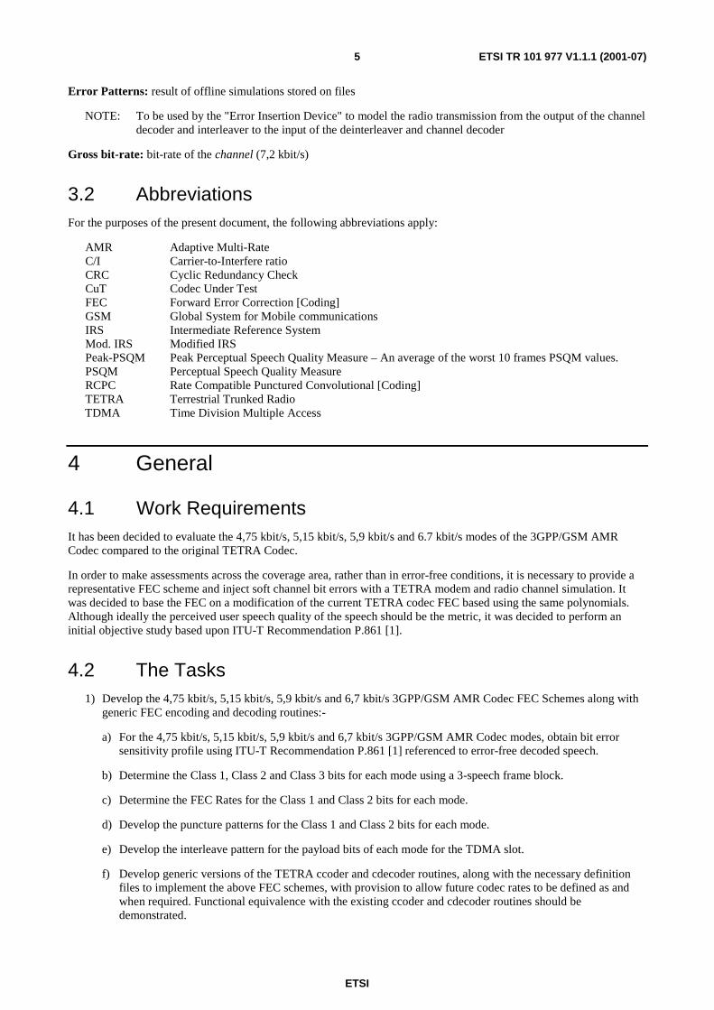
4.1 Work RequirementsIt has been decided to evaluate the 4,75 kbit/s, 5,15 kbit/s, 5,9 kbit/s and 6.7 kbit/s modes of the 3GPP/GSM AMRCodec compared to the original TETRA Codec.
In order to make assessments across the coverage area, rather than in error-free conditions, it is necessary to provide arepresentative FEC scheme and inject soft channel bit errors with a TETRA modem and radio channel simulation. Itwas decided to base the FEC on a modification of the current TETRA codec FEC based using the same polynomials.Although ideally the perceived user speech quality of the speech should be the metric, it was decided to perform aninitial objective study based upon ITU-T Recommendation P.861 [1].
4.2 The Tasks1) Develop the 4,75 kbit/s, 5,15 kbit/s, 5,9 kbit/s and 6,7 kbit/s 3GPP/GSM AMR Codec FEC Schemes along with
generic FEC encoding and decoding routines:-
a) For the 4,75 kbit/s, 5,15 kbit/s, 5,9 kbit/s and 6,7 kbit/s 3GPP/GSM AMR Codec modes, obtain bit errorsensitivity profile using ITU-T Recommendation P.861 [1] referenced to error-free decoded speech.
b) Determine the Class 1, Class 2 and Class 3 bits for each mode using a 3-speech frame block.
c) Determine the FEC Rates for the Class 1 and Class 2 bits for each mode.
d) Develop the puncture patterns for the Class 1 and Class 2 bits for each mode.
e) Develop the interleave pattern for the payload bits of each mode for the TDMA slot.
f) Develop generic versions of the TETRA ccoder and cdecoder routines, along with the necessary definitionfiles to implement the above FEC schemes, with provision to allow future codec rates to be defined as andwhen required. Functional equivalence with the existing ccoder and cdecoder routines should bedemonstrated.
ETSI
ETSI TR 101 977 V1.1.1 (2001-07)6
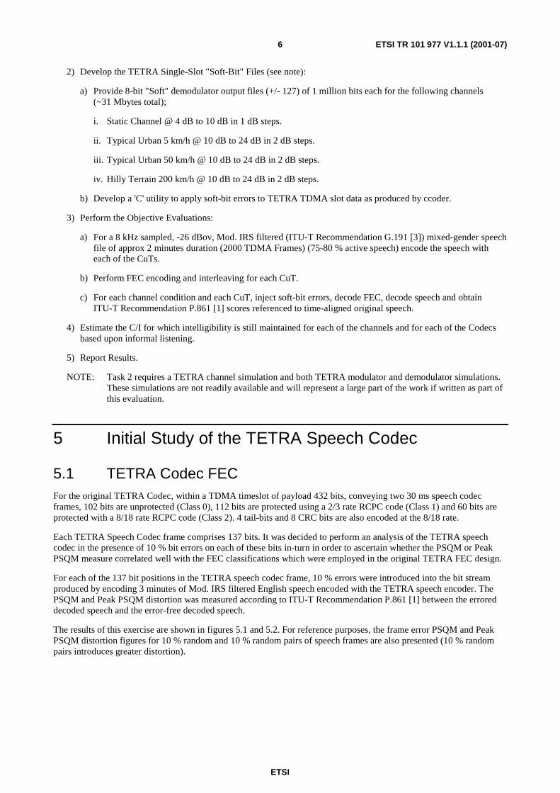
2) Develop the TETRA Single-Slot "Soft-Bit" Files (see note):
a) Provide 8-bit "Soft" demodulator output files (+/- 127) of 1 million bits each for the following channels(~31 Mbytes total);
i. Static Channel @ 4 dB to 10 dB in 1 dB steps.
ii. Typical Urban 5 km/h @ 10 dB to 24 dB in 2 dB steps.
iii. Typical Urban 50 km/h @ 10 dB to 24 dB in 2 dB steps.
iv. Hilly Terrain 200 km/h @ 10 dB to 24 dB in 2 dB steps.
b) Develop a 'C' utility to apply soft-bit errors to TETRA TDMA slot data as produced by ccoder.
3) Perform the Objective Evaluations:
a) For a 8 kHz sampled, -26 dBov, Mod. IRS filtered (ITU-T Recommendation G.191 [3]) mixed-gender speechfile of approx 2 minutes duration (2000 TDMA Frames) (75-80 % active speech) encode the speech witheach of the CuTs.
b) Perform FEC encoding and interleaving for each CuT.
c) For each channel condition and each CuT, inject soft-bit errors, decode FEC, decode speech and obtainITU-T Recommendation P.861 [1] scores referenced to time-aligned original speech.
4) Estimate the C/I for which intelligibility is still maintained for each of the channels and for each of the Codecsbased upon informal listening.
5) Report Results.
NOTE: Task 2 requires a TETRA channel simulation and both TETRA modulator and demodulator simulations.These simulations are not readily available and will represent a large part of the work if written as part ofthis evaluation.
5 Initial Study of the TETRA Speech Codec
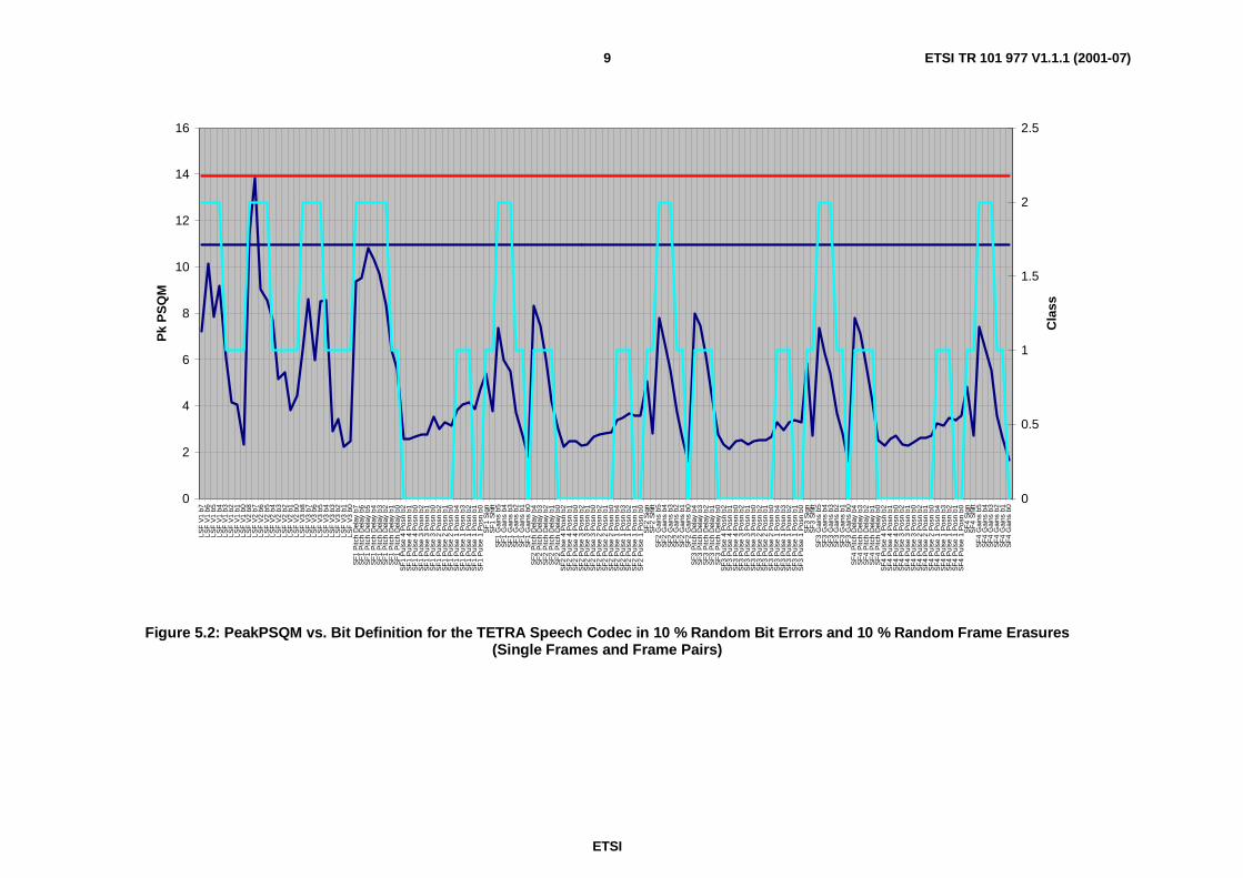
5.1 TETRA Codec FECFor the original TETRA Codec, within a TDMA timeslot of payload 432 bits, conveying two 30 ms speech codecframes, 102 bits are unprotected (Class 0), 112 bits are protected using a 2/3 rate RCPC code (Class 1) and 60 bits areprotected with a 8/18 rate RCPC code (Class 2). 4 tail-bits and 8 CRC bits are also encoded at the 8/18 rate.
Each TETRA Speech Codec frame comprises 137 bits. It was decided to perform an analysis of the TETRA speechcodec in the presence of 10 % bit errors on each of these bits in-turn in order to ascertain whether the PSQM or PeakPSQM measure correlated well with the FEC classifications which were employed in the original TETRA FEC design.
For each of the 137 bit positions in the TETRA speech codec frame, 10 % errors were introduced into the bit streamproduced by encoding 3 minutes of Mod. IRS filtered English speech encoded with the TETRA speech encoder. ThePSQM and Peak PSQM distortion was measured according to ITU-T Recommendation P.861 [1] between the erroreddecoded speech and the error-free decoded speech.
The results of this exercise are shown in figures 5.1 and 5.2. For reference purposes, the frame error PSQM and PeakPSQM distortion figures for 10 % random and 10 % random pairs of speech frames are also presented (10 % randompairs introduces greater distortion).

ETSI
ETSI TR 101 977 V1.1.1 (2001-07)7
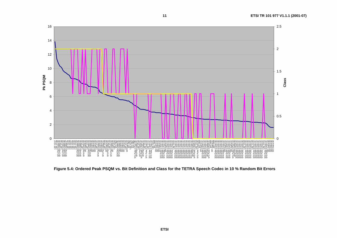
5.2 PSQM or Peak-PSQM For Error Sensitivity?In order to determine if PSQM or Peak PSQM provides are better indicator of Speech Class for the TETRA codec weordered the distortion values in decreasing order of distortion and compared the predicted Class with the actual Class.
The curves for the two distortion measures are presented in figures 5.3 and 5.4.
Figure 5.3 shows that 11 of the 30 bits of Class 2 are incorrectly classified and 17 of the 51 Class 0 bits are alsomisclassified. Perhaps the most apparent outlier bit is bit 8 of LSF Vector 3 which is not grouped with the other bitsmisclassified from Class 2.
In contrast, figure 5.4 shows that only 8 of the 30 bits of Class 2 are incorrectly classified and 12 of the 51 Class 0 bitsare misclassified. In addition, the misclassifications are well clustered and remain broadly in the correct order.
In conclusion, it seems reasonable to assume that the Peak PSQM of the Worst 10 frames is a better metric for definingthe classes than the conventional PSM measure since it correlates better with the classifications used in the originalTETRA Codec.

ETSI
ETSI TR 101 977 V1.1.1 (2001-07)8
0
0.2
0.4
0.6
0.8
1
1.2
1.4
LSF
V1
b7LS
FV
1b6
LSF
V1
b5LS
FV
1b4
LSF
V1
b3LS
FV
1b2
LSF
V1
b1LS
FV
1b0
LSF
V2
b8LS
FV
2b7
LSF
V2
b6LS
FV
2b5
LSF
V2
b4LS
FV
2b3
LSF
V2
b2LS
FV
2b1
LSF
V2
b0LS
FV
3b8
LSF
V3
b7LS
FV
3b6
LSF
V3
b5LS
FV
3b4
LSF
V3
b3LS
FV
3b2
LSF
V3
b1LS
FV
3b0
SF
1P
itch
Del
ayb7
SF
1P
itch
Del
ayb6
SF
1P
itch
Del
ayb5
SF
1P
itch
Del
ayb4
SF
1P
itch
Del
ayb3
SF
1P
itch
Del
ayb2
SF
1P
itch
Del
ayb1
SF
1P
itch
Del
ayb0
SF
1P
ulse
4P
osn
b2S
F1
Pul
se4
Pos
nb1
SF
1P
ulse
4P
osn
b0S
F1
Pul
se3
Pos
nb2
SF
1P
ulse
3P
osn
b1S
F1
Pul
se3
Pos
nb0
SF
1P
ulse
2P
osn
b2S
F1
Pul
se2
Pos
nb1
SF
1P
ulse
2P
osn
b0S
F1
Pul
se1
Pos
nb4
SF
1P
ulse
1P
osn
b3S
F1
Pul
se1
Pos
nb2
SF
1P
ulse
1P
osn
b1S
F1
Pul
se1
Pos
nb0
SF
1S
ign
SF
1S
hift
SF
1G
ains
b5S
F1
Gai
nsb4
SF
1G
ains
b3S
F1
Gai
nsb2
SF
1G
ains
b1S
F1
Gai
nsb0
SF
2P
itch
Del
ayb4
SF
2P
itch
Del
ayb3
SF
2P
itch
Del
ayb2
SF
2P
itch
Del
ayb1
SF
2P
itch
Del
ayb0
SF
2P
ulse
4P
osn
b2S
F2
Pul
se4
Pos
nb1
SF
2P
ulse
4P
osn
b0S
F2
Pul
se3
Pos
nb2
SF
2P
ulse
3P
osn
b1S
F2
Pul
se3
Pos
nb0
SF
2P
ulse
2P
osn
b2S
F2
Pul
se2
Pos
nb1
SF
2P
ulse
2P
osn
b0S
F2
Pul
se1
Pos
nb4
SF
2P
ulse
1P
osn
b3S
F2
Pul
se1
Pos
nb2
SF
2P
ulse
1P
osn
b1S
F2
Pul
se1
Pos
nb0
SF
2S
ign
SF
2S
hift
SF
2G
ains
b5S
F2
Gai
nsb4
SF
2G
ains
b3S
F2
Gai
nsb2
SF
2G
ains
b1S
F2
Gai
nsb0
SF
3P
itch
Del
ayb4
SF
3P
itch
Del
ayb3
SF
3P
itch
Del
ayb2
SF
3P
itch
Del
ayb1
SF
3P
itch
Del
ayb0
SF
3P
ulse
4P
osn
b2S
F3
Pul
se4
Pos
nb1
SF
3P
ulse
4P
osn
b0S
F3
Pul
se3
Pos
nb2
SF
3P
ulse
3P
osn
b1S
F3
Pul
se3
Pos
nb0
SF
3P
ulse
2P
osn
b2S
F3
Pul
se2
Pos
nb1
SF
3P
ulse
2P
osn
b0S
F3
Pul
se1
Pos
nb4
SF
3P
ulse
1P
osn
b3S
F3
Pul
se1
Pos
nb2
SF
3P
ulse
1P
osn
b1S
F3
Pul
se1
Pos
nb0
SF
3S
ign
SF
3S
hift
SF
3G
ains
b5S
F3
Gai
nsb4
SF
3G
ains
b3S
F3
Gai
nsb2
SF
3G
ains
b1S
F3
Gai
nsb0
SF
4P
itch
Del
ayb4
SF
4P
itch
Del
ayb3
SF
4P
itch
Del
ayb2
SF
4P
itch
Del
ayb1
SF
4P
itch
Del
ayb0
SF
4P
ulse
4P
osn
b2S
F4
Pul
se4
Pos
nb1
SF
4P
ulse
4P
osn
b0S
F4
Pul
se3
Pos
nb2
SF
4P
ulse
3P
osn
b1S
F4
Pul
se3
Pos
nb0
SF
4P
ulse
2P
osn
b2S
F4
Pul
se2
Pos
nb1
SF
4P
ulse
2P
osn
b0S
F4
Pul
se1
Pos
nb4
SF
4P
ulse
1P
osn
b3S
F4
Pul
se1
Pos
nb2
SF
4P
ulse
1P
osn
b1S
F4
Pul
se1
Pos
nb0
SF
4S
ign
SF
4S
hift
SF
4G
ains
b5S
F4
Gai
nsb4
SF
4G
ains
b3S
F4
Gai
nsb2
SF
4G
ains
b1S
F4
Gai
nsb0
Av
PS
QM
0
0.5
1
1.5
2
2.5
Cla
ss
Figure 5.1: PSQM vs. Bit Definition for the TETRA Speech Codec in 10 % Random Bit Errors and 10 % Random Frame Erasures(Single Frames and Frame Pairs)
ETSI
ETSI TR 101 977 V1.1.1 (2001-07)9
0
2
4
6
8
10
12
14
16
LSF
V1
b7LS
FV
1b6
LSF
V1
b5LS
FV
1b4
LSF
V1
b3LS
FV
1b2
LSF
V1
b1LS
FV
1b0
LSF
V2
b8LS
FV
2b7
LSF
V2
b6LS
FV
2b5
LSF
V2
b4LS
FV
2b3
LSF
V2
b2LS
FV
2b1
LSF
V2
b0LS
FV
3b8
LSF
V3
b7LS
FV
3b6
LSF
V3
b5LS
FV
3b4
LSF
V3
b3LS
FV
3b2
LSF
V3
b1LS
FV
3b0
SF
1P
itch
Del
ayb7
SF
1P
itch
Del
ayb6
SF
1P
itch
Del
ayb5
SF
1P
itch
Del
ayb4
SF
1P
itch
Del
ayb3
SF
1P
itch
Del
ayb2
SF
1P
itch
Del
ayb1
SF
1P
itch
Del
ayb0
SF
1P
ulse
4P
osn
b2S
F1
Pul
se4
Pos
nb1
SF
1P
ulse
4P
osn
b0S
F1
Pul
se3
Pos
nb2
SF
1P
ulse
3P
osn
b1S
F1
Pul
se3
Pos
nb0
SF
1P
ulse
2P
osn
b2S
F1
Pul
se2
Pos
nb1
SF
1P
ulse
2P
osn
b0S
F1
Pul
se1
Pos
nb4
SF
1P
ulse
1P
osn
b3S
F1
Pul
se1
Pos
nb2
SF
1P
ulse
1P
osn
b1S
F1
Pul
se1
Pos
nb0
SF
1S
ign
SF
1S
hift
SF
1G
ains
b5S
F1
Gai
nsb4
SF
1G
ains
b3S
F1
Gai
nsb2
SF
1G
ains
b1S
F1
Gai
nsb0
SF
2P
itch
Del
ayb4
SF
2P
itch
Del
ayb3
SF
2P
itch
Del
ayb2
SF
2P
itch
Del
ayb1
SF
2P
itch
Del
ayb0
SF
2P
ulse
4P
osn
b2S
F2
Pul
se4
Pos
nb1
SF
2P
ulse
4P
osn
b0S
F2
Pul
se3
Pos
nb2
SF
2P
ulse
3P
osn
b1S
F2
Pul
se3
Pos
nb0
SF
2P
ulse
2P
osn
b2S
F2
Pul
se2
Pos
nb1
SF
2P
ulse
2P
osn
b0S
F2
Pul
se1
Pos
nb4
SF
2P
ulse
1P
osn
b3S
F2
Pul
se1
Pos
nb2
SF
2P
ulse
1P
osn
b1S
F2
Pul
se1
Pos
nb0
SF
2S
ign
SF
2S
hift
SF
2G
ains
b5S
F2
Gai
nsb4
SF
2G
ains
b3S
F2
Gai
nsb2
SF
2G
ains
b1S
F2
Gai
nsb0
SF
3P
itch
Del
ayb4
SF
3P
itch
Del
ayb3
SF
3P
itch
Del
ayb2
SF
3P
itch
Del
ayb1
SF
3P
itch
Del
ayb0
SF
3P
ulse
4P
osn
b2S
F3
Pul
se4
Pos
nb1
SF
3P
ulse
4P
osn
b0S
F3
Pul
se3
Pos
nb2
SF
3P
ulse
3P
osn
b1S
F3
Pul
se3
Pos
nb0
SF
3P
ulse
2P
osn
b2S
F3
Pul
se2
Pos
nb1
SF
3P
ulse
2P
osn
b0S
F3
Pul
se1
Pos
nb4
SF
3P
ulse
1P
osn
b3S
F3
Pul
se1
Pos
nb2
SF
3P
ulse
1P
osn
b1S
F3
Pul
se1
Pos
nb0
SF
3S
ign
SF
3S
hift
SF
3G
ains
b5S
F3
Gai
nsb4
SF
3G
ains
b3S
F3
Gai
nsb2
SF
3G
ains
b1S
F3
Gai
nsb0
SF
4P
itch
Del
ayb4
SF
4P
itch
Del
ayb3
SF
4P
itch
Del
ayb2
SF
4P
itch
Del
ayb1
SF
4P
itch
Del
ayb0
SF
4P
ulse
4P
osn
b2S
F4
Pul
se4
Pos
nb1
SF
4P
ulse
4P
osn
b0S
F4
Pul
se3
Pos
nb2
SF
4P
ulse
3P
osn
b1S
F4
Pul
se3
Pos
nb0
SF
4P
ulse
2P
osn
b2S
F4
Pul
se2
Pos
nb1
SF
4P
ulse
2P
osn
b0S
F4
Pul
se1
Pos
nb4
SF
4P
ulse
1P
osn
b3S
F4
Pul
se1
Pos
nb2
SF
4P
ulse
1P
osn
b1S
F4
Pul
se1
Pos
nb0
SF
4S
ign
SF
4S
hift
SF
4G
ains
b5S
F4
Gai
nsb4
SF
4G
ains
b3S
F4
Gai
nsb2
SF
4G
ains
b1S
F4
Gai
nsb0
Pk
PS
QM
0
0.5
1
1.5
2
2.5
Cla
ss
Figure 5.2: PeakPSQM vs. Bit Definition for the TETRA Speech Codec in 10 % Random Bit Errors and 10 % Random Frame Erasures(Single Frames and Frame Pairs)

ETSI
ETSI TR 101 977 V1.1.1 (2001-07)10
0
0.2
0.4
0.6
0.8
1
1.2
SF
1P
itch
Del
ayb5
SF
1P
itch
Del
ayb4
SF
1P
itch
Del
ayb6
SF
1P
itch
Del
ayb7
SF
1P
itch
Del
ayb3
SF
1P
itch
Del
ayb2
LSF
V1
b6LS
FV
2b7
SF
3P
itch
Del
ayb4
SF
4P
itch
Del
ayb4
SF
2P
itch
Del
ayb4
LSF
V2
b8S
F1
Pitc
hD
elay
b1S
F3
Gai
nsb5
SF
1G
ains
b5S
F4
Pitc
hD
elay
b3S
F2
Gai
nsb5
SF
3P
itch
Del
ayb3
SF
2P
itch
Del
ayb3
SF
4G
ains
b5LS
FV
2b6
LSF
V1
b5S
F2
Pitc
hD
elay
b2S
F3
Pitc
hD
elay
b2S
F4
Pitc
hD
elay
b2S
F2
Gai
nsb4
SF
1G
ains
b4S
F4
Gai
nsb4
SF
3G
ains
b4S
F2
Sig
nLS
FV
2b5
SF
1S
ign
SF
3S
ign
LSF
V1
b7S
F4
Sig
nS
F1
Pitc
hD
elay
b0S
F4
Pitc
hD
elay
b1S
F2
Pitc
hD
elay
b1S
F3
Pitc
hD
elay
b1S
F1
Gai
nsb3
LSF
V1
b4S
F4
Gai
nsb3
LSF
V2
b4S
F3
Gai
nsb3
SF
2G
ains
b3LS
FV
3b6
LSF
V3
b7S
F2
Pul
se1
Pos
nb2
SF
1P
ulse
1P
osn
b1S
F2
Pul
se1
Pos
nb1
SF
1P
ulse
1P
osn
b2S
F1
Shi
ftLS
FV
3b5
SF
2S
hift
SF
1P
ulse
1P
osn
b0S
F2
Pul
se1
Pos
nb4
SF
1P
ulse
1P
osn
b3S
F1
Pul
se1
Pos
nb4
SF
3P
ulse
1P
osn
b2S
F3
Pul
se1
Pos
nb1
SF
4P
ulse
1P
osn
b2S
F4
Pul
se1
Pos
nb1
SF
2P
ulse
1P
osn
b3S
F2
Pul
se1
Pos
nb0
LSF
V2
b3S
F3
Shi
ftS
F3
Pul
se1
Pos
nb4
SF
3P
ulse
1P
osn
b3S
F4
Shi
ftS
F4
Pul
se1
Pos
nb3
SF
2P
itch
Del
ayb0
SF
4P
ulse
1P
osn
b4S
F3
Pitc
hD
elay
b0S
F3
Pul
se1
Pos
nb0
SF
4P
itch
Del
ayb0
SF
4P
ulse
1P
osn
b0LS
FV
1b3
LSF
V3
b8LS
FV
2b2
SF
2P
ulse
2P
osn
b0S
F1
Pul
se2
Pos
nb0
LSF
V3
b4S
F2
Pul
se2
Pos
nb1
SF
3P
ulse
2P
osn
b0S
F2
Pul
se2
Pos
nb2
SF
1P
ulse
2P
osn
b2S
F1
Pul
se2
Pos
nb1
SF
4G
ains
b2S
F4
Pul
se2
Pos
nb0
SF
1P
ulse
3P
osn
b0S
F2
Pul
se3
Pos
nb0
SF
1P
ulse
4P
osn
b0S
F1
Gai
nsb2
SF
2P
ulse
4P
osn
b0S
F3
Gai
nsb2
SF
3P
ulse
2P
osn
b2S
F1
Pul
se3
Pos
nb1
SF
3P
ulse
3P
osn
b0S
F3
Pul
se2
Pos
nb1
SF
2P
ulse
3P
osn
b2S
F1
Pul
se3
Pos
nb2
SF
4P
ulse
2P
osn
b2LS
FV
1b1
SF
2G
ains
b2S
F4
Pul
se2
Pos
nb1
LSF
V1
b2S
F2
Pul
se4
Pos
nb1
SF
2P
ulse
3P
osn
b1S
F2
Pul
se4
Pos
nb2
SF
1P
ulse
4P
osn
b2S
F1
Pul
se4
Pos
nb1
SF
4P
ulse
4P
osn
b0LS
FV
2b1
SF
3P
ulse
3P
osn
b2S
F3
Pul
se4
Pos
nb0
SF
3P
ulse
3P
osn
b1S
F4
Pul
se3
Pos
nb0
SF
3P
ulse
4P
osn
b2S
F4
Pul
se3
Pos
nb2
SF
1G
ains
b1S
F4
Pul
se4
Pos
nb2
SF
3P
ulse
4P
osn
b1S
F4
Pul
se3
Pos
nb1
SF
4P
ulse
4P
osn
b1LS
FV
2b0
SF
3G
ains
b1S
F2
Gai
nsb1
LSF
V1
b0S
F4
Gai
nsb1
LSF
V3
b3LS
FV
3b2
SF
2G
ains
b0LS
FV
3b1
SF
1G
ains
b0S
F3
Gai
nsb0
SF
4G
ains
b0LS
FV
3b0
Av
PS
QM
0
0.5
1
1.5
2
2.5
Cla
ss
Figure 5.3: Ordered PSQM vs. Bit Definition and Class for the TETRA Speech Codec in 10 % Random Bit Errors
ETSI
ETSI TR 101 977 V1.1.1 (2001-07)11
0
2
4
6
8
10
12
14
16
LSF
V2
b7LS
FV
2b8
SF
1P
itch
Del
ayb5
SF
1P
itch
Del
ayb4
LSF
V1
b6S
F1
Pitc
hD
elay
b3S
F1
Pitc
hD
elay
b6S
F1
Pitc
hD
elay
b7LS
FV
1b4
LSF
V2
b6LS
FV
3b7
LSF
V3
b4LS
FV
2b5
LSF
V3
b5S
F1
Pitc
hD
elay
b2S
F2
Pitc
hD
elay
b4S
F3
Pitc
hD
elay
b4LS
FV
1b5
SF
4P
itch
Del
ayb4
SF
2G
ains
b5LS
FV
2b4
SF
2P
itch
Del
ayb3
SF
3P
itch
Del
ayb3
SF
4G
ains
b5S
F1
Gai
nsb5
SF
3G
ains
b5LS
FV
1b7
SF
4P
itch
Del
ayb3
SF
2G
ains
b4S
F4
Gai
nsb4
SF
1P
itch
Del
ayb1
LSF
V3
b8S
F3
Gai
nsb4
SF
3P
itch
Del
ayb2
LSF
V1
b3S
F2
Pitc
hD
elay
b2S
F1
Gai
nsb4
LSF
V3
b6S
F3
Sig
nS
F4
Pitc
hD
elay
b2S
F1
Pitc
hD
elay
b0S
F4
Gai
nsb3
SF
2G
ains
b3S
F1
Gai
nsb3
LSF
V2
b2S
F3
Gai
nsb3
SF
1S
ign
LSF
V2
b3S
F2
Sig
nS
F4
Sig
nS
F1
Pul
se1
Pos
nb0
SF
3P
itch
Del
ayb1
LSF
V2
b0S
F2
Pitc
hD
elay
b1S
F1
Pul
se1
Pos
nb2
SF
4P
itch
Del
ayb1
LSF
V1
b2S
F1
Pul
se1
Pos
nb3
LSF
V1
b1S
F1
Pul
se1
Pos
nb1
SF
1P
ulse
1P
osn
b4LS
FV
2b1
SF
1S
hift
SF
2G
ains
b2S
F1
Gai
nsb2
SF
3G
ains
b2S
F2
Pul
se1
Pos
nb2
SF
4P
ulse
1P
osn
b0S
F2
Pul
se1
Pos
nb0
SF
4G
ains
b2S
F2
Pul
se1
Pos
nb1
SF
1P
ulse
3P
osn
b0S
F2
Pul
se1
Pos
nb3
SF
4P
ulse
1P
osn
b2LS
FV
3b2
SF
3P
ulse
1P
osn
b1S
F4
Pul
se1
Pos
nb1
SF
2P
ulse
1P
osn
b4S
F3
Pul
se1
Pos
nb2
SF
3P
ulse
1P
osn
b0S
F1
Pul
se2
Pos
nb1
SF
3P
ulse
1P
osn
b4S
F4
Pul
se1
Pos
nb4
SF
1P
ulse
2P
osn
b0S
F4
Pul
se1
Pos
nb3
SF
1P
ulse
2P
osn
b2S
F2
Pitc
hD
elay
b0S
F3
Pul
se1
Pos
nb3
LSF
V3
b3S
F2
Pul
se2
Pos
nb0
SF
2S
hift
SF
3G
ains
b1S
F2
Pul
se2
Pos
nb1
SF
1P
ulse
3P
osn
b2S
F2
Pul
se2
Pos
nb2
SF
3P
itch
Del
ayb0
SF
1P
ulse
3P
osn
b1S
F4
Shi
ftS
F1
Gai
nsb1
SF
3S
hift
SF
4P
ulse
2P
osn
b0S
F4
Pul
se4
Pos
nb0
SF
1P
ulse
4P
osn
b0S
F2
Pul
se3
Pos
nb0
SF
3P
ulse
2P
osn
b0S
F4
Pul
se2
Pos
nb2
SF
4G
ains
b1S
F4
Pul
se2
Pos
nb1
SF
1P
ulse
4P
osn
b1S
F4
Pul
se4
Pos
nb1
SF
2G
ains
b1S
F1
Pul
se4
Pos
nb2
SF
4P
itch
Del
ayb0
SF
3P
ulse
2P
osn
b2S
F3
Pul
se3
Pos
nb2
SF
3P
ulse
2P
osn
b1S
F2
Pul
se4
Pos
nb1
SF
3P
ulse
3P
osn
b0LS
FV
3b0
SF
2P
ulse
4P
osn
b0S
F3
Pul
se4
Pos
nb0
SF
4P
ulse
3P
osn
b0S
F3
Pul
se3
Pos
nb1
LSF
V1
b0S
F4
Pul
se3
Pos
nb2
SF
2P
ulse
3P
osn
b1S
F3
Pul
se4
Pos
nb2
SF
4P
ulse
3P
osn
b1S
F4
Pul
se4
Pos
nb2
SF
2P
ulse
3P
osn
b2LS
FV
3b1
SF
2P
ulse
4P
osn
b2S
F3
Pul
se4
Pos
nb1
SF
1G
ains
b0S
F4
Gai
nsb0
SF
3G
ains
b0S
F2
Gai
nsb0
Pk
PS
QM
0
0.5
1
1.5
2
2.5
Cla
ss
Figure 5.4: Ordered Peak PSQM vs. Bit Definition and Class for the TETRA Speech Codec in 10 % Random Bit Errors

ETSI
ETSI TR 101 977 V1.1.1 (2001-07)12
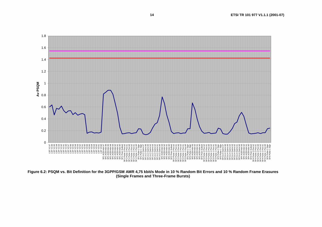
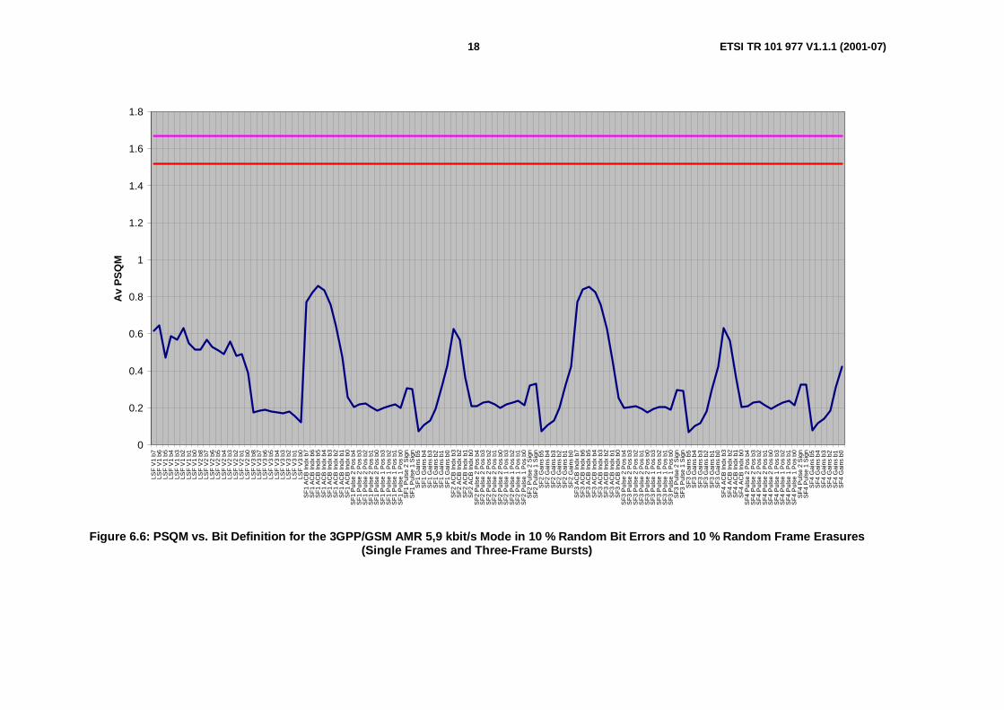
6 PSQM Values for GSM AMR Codec
6.1 4,75 kbit/s ModeSee figures 6.1 and 6.2.
6.2 5,15 kbit/s ModeSee figures 6.3 and 6.4.
6.3 5,9 kbit/s ModeSee figures 6.5 and 6.6.
6.4 6,7 kbit/s ModeSee figures 6.7 and 6.8.

13 ETSI TR 101 977 V1.1.1 (2001-07)
0
2
4
6
8
10
12
14
16
LSF
V1
b7LS
FV
1b6
LSF
V1
b5LS
FV
1b4
LSF
V1
b3LS
FV
1b2
LSF
V1
b1LS
FV
1b0
LSF
V2
b7LS
FV
2b6
LSF
V2
b5LS
FV
2b4
LSF
V2
b3LS
FV
2b2
LSF
V2
b1LS
FV
2b0
LSF
V3
b6LS
FV
3b5
LSF
V3
b4LS
FV
3b3
LSF
V3
b2LS
FV
3b1
LSF
V3
b0S
F1
AC
BIn
dxb7
SF
1A
CB
Indx
b6S
F1
AC
BIn
dxb5
SF
1A
CB
Indx
b4S
F1
AC
BIn
dxb3
SF
1A
CB
Indx
b2S
F1
AC
BIn
dxb1
SF
1A
CB
Indx
b0S
F1
Pos
nS
ubse
tS
F1
Pul
se2
Pos
b2S
F1
Pul
se2
Pos
b1S
F1
Pul
se2
Pos
b0S
F1
Pul
se1
Pos
b2S
F1
Pul
se1
Pos
b1S
F1
Pul
se1
Pos
b0S
F1
Pul
se2
Sig
nS
F1
Pul
se1
Sig
nS
F1
&2
Gai
nsb7
SF
1&
2G
ains
b6S
F1
&2
Gai
nsb5
SF
1&
2G
ains
b4S
F1
&2
Gai
nsb3
SF
1&
2G
ains
b2S
F1
&2
Gai
nsb1
SF
1&
2G
ains
b0S
F2
AC
BIn
dxb3
SF
2A
CB
Indx
b2S
F2
AC
BIn
dxb1
SF
2A
CB
Indx
b0S
F2
Pos
nS
ubse
tS
F2
Pul
se2
Pos
b2S
F2
Pul
se2
Pos
b1S
F2
Pul
se2
Pos
b0S
F2
Pul
se1
Pos
b2S
F2
Pul
se1
Pos
b1S
F2
Pul
se1
Pos
b0S
F2
Pul
se2
Sig
nS
F2
Pul
se1
Sig
nS
F3
AC
BIn
dxb3
SF
3A
CB
Indx
b2S
F3
AC
BIn
dxb1
SF
3A
CB
Indx
b0S
F3
Pos
nS
ubse
tS
F3
Pul
se2
Pos
b2S
F3
Pul
se2
Pos
b1S
F3
Pul
se2
Pos
b0S
F3
Pul
se1
Pos
b2S
F3
Pul
se1
Pos
b1S
F3
Pul
se1
Pos
b0S
F3
Pul
se2
Sig
nS
F3
Pul
se1
Sig
nS
F3
&4
Gai
nsb7
SF
3&
4G
ains
b6S
F3
&4
Gai
nsb5
SF
3&
4G
ains
b4S
F3
&4
Gai
nsb3
SF
3&
4G
ains
b2S
F3
&4
Gai
nsb1
SF
3&
4G
ains
b0S
F4
AC
BIn
dxb3
SF
4A
CB
Indx
b2S
F4
AC
BIn
dxb1
SF
4A
CB
Indx
b0S
F4
Pos
nS
ubse
tS
F4
Pul
se2
Pos
b2S
F4
Pul
se2
Pos
b1S
F4
Pul
se2
Pos
b0S
F4
Pul
se1
Pos
b2S
F4
Pul
se1
Pos
b1S
F4
Pul
se1
Pos
b0S
F4
Pul
se2
Sig
nS
F4
Pul
se1
Sig
n
Pk
PS
QM
Figure 6.1: Peak PSQM vs. Bit Definition for the 3GPP/GSM AMR 4,75 kbit/s Mode in 10 % Random Bit Errors and 10 % Random Frame Erasures(Single Frames and Three-Frame Bursts)
14 ETSI TR 101 977 V1.1.1 (2001-07)
0
0.2
0.4
0.6
0.8
1
1.2
1.4
1.6
1.8
LSF
V1
b7LS
FV
1b6
LSF
V1
b5LS
FV
1b4
LSF
V1
b3LS
FV
1b2
LSF
V1
b1LS
FV
1b0
LSF
V2
b7LS
FV
2b6
LSF
V2
b5LS
FV
2b4
LSF
V2
b3LS
FV
2b2
LSF
V2
b1LS
FV
2b0
LSF
V3
b6LS
FV
3b5
LSF
V3
b4LS
FV
3b3
LSF
V3
b2LS
FV
3b1
LSF
V3
b0S
F1
AC
BIn
dxb7
SF
1A
CB
Indx
b6S
F1
AC
BIn
dxb5
SF
1A
CB
Indx
b4S
F1
AC
BIn
dxb3
SF
1A
CB
Indx
b2S
F1
AC
BIn
dxb1
SF
1A
CB
Indx
b0S
F1
Pos
nS
ubse
tS
F1
Pul
se2
Pos
b2S
F1
Pul
se2
Pos
b1S
F1
Pul
se2
Pos
b0S
F1
Pul
se1
Pos
b2S
F1
Pul
se1
Pos
b1S
F1
Pul
se1
Pos
b0S
F1
Pul
se2
Sig
nS
F1
Pul
se1
Sig
nS
F1
&2
Gai
nsb7
SF
1&
2G
ains
b6S
F1
&2
Gai
nsb5
SF
1&
2G
ains
b4S
F1
&2
Gai
nsb3
SF
1&
2G
ains
b2S
F1
&2
Gai
nsb1
SF
1&
2G
ains
b0S
F2
AC
BIn
dxb3
SF
2A
CB
Indx
b2S
F2
AC
BIn
dxb1
SF
2A
CB
Indx
b0S
F2
Pos
nS
ubse
tS
F2
Pul
se2
Pos
b2S
F2
Pul
se2
Pos
b1S
F2
Pul
se2
Pos
b0S
F2
Pul
se1
Pos
b2S
F2
Pul
se1
Pos
b1S
F2
Pul
se1
Pos
b0S
F2
Pul
se2
Sig
nS
F2
Pul
se1
Sig
nS
F3
AC
BIn
dxb3
SF
3A
CB
Indx
b2S
F3
AC
BIn
dxb1
SF
3A
CB
Indx
b0S
F3
Pos
nS
ubse
tS
F3
Pul
se2
Pos
b2S
F3
Pul
se2
Pos
b1S
F3
Pul
se2
Pos
b0S
F3
Pul
se1
Pos
b2S
F3
Pul
se1
Pos
b1S
F3
Pul
se1
Pos
b0S
F3
Pul
se2
Sig
nS
F3
Pul
se1
Sig
nS
F3
&4
Gai
nsb7
SF
3&
4G
ains
b6S
F3
&4
Gai
nsb5
SF
3&
4G
ains
b4S
F3
&4
Gai
nsb3
SF
3&
4G
ains
b2S
F3
&4
Gai
nsb1
SF
3&
4G
ains
b0S
F4
AC
BIn
dxb3
SF
4A
CB
Indx
b2S
F4
AC
BIn
dxb1
SF
4A
CB
Indx
b0S
F4
Pos
nS
ubse
tS
F4
Pul
se2
Pos
b2S
F4
Pul
se2
Pos
b1S
F4
Pul
se2
Pos
b0S
F4
Pul
se1
Pos
b2S
F4
Pul
se1
Pos
b1S
F4
Pul
se1
Pos
b0S
F4
Pul
se2
Sig
nS
F4
Pul
se1
Sig
n
Av
PS
QM
Figure 6.2: PSQM vs. Bit Definition for the 3GPP/GSM AMR 4,75 kbit/s Mode in 10 % Random Bit Errors and 10 % Random Frame Erasures(Single Frames and Three-Frame Bursts)

15 ETSI TR 101 977 V1.1.1 (2001-07)
0
2
4
6
8
10
12
14
16
LSF
V1
b7LS
FV
1b6
LSF
V1
b5LS
FV
1b4
LSF
V1
b3LS
FV
1b2
LSF
V1
b1LS
FV
1b0
LSF
V2
b7LS
FV
2b6
LSF
V2
b5LS
FV
2b4
LSF
V2
b3LS
FV
2b2
LSF
V2
b1LS
FV
2b0
LSF
V3
b6LS
FV
3b5
LSF
V3
b4LS
FV
3b3
LSF
V3
b2LS
FV
3b1
LSF
V3
b0S
F1
AC
BIn
dxb7
SF
1A
CB
Indx
b6S
F1
AC
BIn
dxb5
SF
1A
CB
Indx
b4S
F1
AC
BIn
dxb3
SF
1A
CB
Indx
b2S
F1
AC
BIn
dxb1
SF
1A
CB
Indx
b0S
F1
Pos
nS
ubse
tS
F1
Pul
se2
Pos
b2S
F1
Pul
se2
Pos
b1S
F1
Pul
se2
Pos
b0S
F1
Pul
se1
Pos
b2S
F1
Pul
se1
Pos
b1S
F1
Pul
se1
Pos
b0S
F1
Pul
se2
Sig
nS
F1
Pul
se1
Sig
nS
F1
Gai
nsb5
SF
1G
ains
b4S
F1
Gai
nsb3
SF
1G
ains
b2S
F1
Gai
nsb1
SF
1G
ains
b0S
F2
AC
BIn
dxb3
SF
2A
CB
Indx
b2S
F2
AC
BIn
dxb1
SF
2A
CB
Indx
b0S
F2
Pos
nS
ubse
tS
F2
Pul
se2
Pos
b2S
F2
Pul
se2
Pos
b1S
F2
Pul
se2
Pos
b0S
F2
Pul
se1
Pos
b2S
F2
Pul
se1
Pos
b1S
F2
Pul
se1
Pos
b0S
F2
Pul
se2
Sig
nS
F2
Pul
se1
Sig
nS
F2
Gai
nsb5
SF
2G
ains
b4S
F2
Gai
nsb3
SF
2G
ains
b2S
F2
Gai
nsb1
SF
2G
ains
b0S
F3
AC
BIn
dxb3
SF
3A
CB
Indx
b2S
F3
AC
BIn
dxb1
SF
3A
CB
Indx
b0S
F3
Pos
nS
ubse
tS
F3
Pul
se2
Pos
b2S
F3
Pul
se2
Pos
b1S
F3
Pul
se2
Pos
b0S
F3
Pul
se1
Pos
b2S
F3
Pul
se1
Pos
b1S
F3
Pul
se1
Pos
b0S
F3
Pul
se2
Sig
nS
F3
Pul
se1
Sig
nS
F3
Gai
nsb5
SF
3G
ains
b4S
F3
Gai
nsb3
SF
3G
ains
b2S
F3
Gai
nsb1
SF
3G
ains
b0S
F4
AC
BIn
dxb3
SF
4A
CB
Indx
b2S
F4
AC
BIn
dxb1
SF
4A
CB
Indx
b0S
F4
Pos
nS
ubse
tS
F4
Pul
se2
Pos
b2S
F4
Pul
se2
Pos
b1S
F4
Pul
se2
Pos
b0S
F4
Pul
se1
Pos
b2S
F4
Pul
se1
Pos
b1S
F4
Pul
se1
Pos
b0S
F4
Pul
se2
Sig
nS
F4
Pul
se1
Sig
nS
F4
Gai
nsb5
SF
4G
ains
b4S
F4
Gai
nsb3
SF
4G
ains
b2S
F4
Gai
nsb1
SF
4G
ains
b0
Pk
PS
QM
Figure 6.3: Peak PSQM vs. Bit Definition for the 3GPP/GSM AMR 5,15 kbit/s Mode in 10 % Random Bit Errors and 10 % Random Frame Erasures(Single Frames and Three-Frame Bursts)

16 ETSI TR 101 977 V1.1.1 (2001-07)
0
0.2
0.4
0.6
0.8
1
1.2
1.4
1.6
LSF
V1
b7LS
FV
1b6
LSF
V1
b5LS
FV
1b4
LSF
V1
b3LS
FV
1b2
LSF
V1
b1LS
FV
1b0
LSF
V2
b7LS
FV
2b6
LSF
V2
b5LS
FV
2b4
LSF
V2
b3LS
FV
2b2
LSF
V2
b1LS
FV
2b0
LSF
V3
b6LS
FV
3b5
LSF
V3
b4LS
FV
3b3
LSF
V3
b2LS
FV
3b1
LSF
V3
b0S
F1
AC
BIn
dxb7
SF
1A
CB
Indx
b6S
F1
AC
BIn
dxb5
SF
1A
CB
Indx
b4S
F1
AC
BIn
dxb3
SF
1A
CB
Indx
b2S
F1
AC
BIn
dxb1
SF
1A
CB
Indx
b0S
F1
Pos
nS
ubse
tS
F1
Pul
se2
Pos
b2S
F1
Pul
se2
Pos
b1S
F1
Pul
se2
Pos
b0S
F1
Pul
se1
Pos
b2S
F1
Pul
se1
Pos
b1S
F1
Pul
se1
Pos
b0S
F1
Pul
se2
Sig
nS
F1
Pul
se1
Sig
nS
F1
Gai
nsb5
SF
1G
ains
b4S
F1
Gai
nsb3
SF
1G
ains
b2S
F1
Gai
nsb1
SF
1G
ains
b0S
F2
AC
BIn
dxb3
SF
2A
CB
Indx
b2S
F2
AC
BIn
dxb1
SF
2A
CB
Indx
b0S
F2
Pos
nS
ubse
tS
F2
Pul
se2
Pos
b2S
F2
Pul
se2
Pos
b1S
F2
Pul
se2
Pos
b0S
F2
Pul
se1
Pos
b2S
F2
Pul
se1
Pos
b1S
F2
Pul
se1
Pos
b0S
F2
Pul
se2
Sig
nS
F2
Pul
se1
Sig
nS
F2
Gai
nsb5
SF
2G
ains
b4S
F2
Gai
nsb3
SF
2G
ains
b2S
F2
Gai
nsb1
SF
2G
ains
b0S
F3
AC
BIn
dxb3
SF
3A
CB
Indx
b2S
F3
AC
BIn
dxb1
SF
3A
CB
Indx
b0S
F3
Pos
nS
ubse
tS
F3
Pul
se2
Pos
b2S
F3
Pul
se2
Pos
b1S
F3
Pul
se2
Pos
b0S
F3
Pul
se1
Pos
b2S
F3
Pul
se1
Pos
b1S
F3
Pul
se1
Pos
b0S
F3
Pul
se2
Sig
nS
F3
Pul
se1
Sig
nS
F3
Gai
nsb5
SF
3G
ains
b4S
F3
Gai
nsb3
SF
3G
ains
b2S
F3
Gai
nsb1
SF
3G
ains
b0S
F4
AC
BIn
dxb3
SF
4A
CB
Indx
b2S
F4
AC
BIn
dxb1
SF
4A
CB
Indx
b0S
F4
Pos
nS
ubse
tS
F4
Pul
se2
Pos
b2S
F4
Pul
se2
Pos
b1S
F4
Pul
se2
Pos
b0S
F4
Pul
se1
Pos
b2S
F4
Pul
se1
Pos
b1S
F4
Pul
se1
Pos
b0S
F4
Pul
se2
Sig
nS
F4
Pul
se1
Sig
nS
F4
Gai
nsb5
SF
4G
ains
b4S
F4
Gai
nsb3
SF
4G
ains
b2S
F4
Gai
nsb1
SF
4G
ains
b0
Av
PS
QM
Figure 6.4: PSQM vs. Bit Definition for the 3GPP/GSM AMR 5,15 kbit/s Mode in 10 % Random Bit Errors and 10 % Random Frame Erasures(Single Frames and Three-Frame Bursts)

17 ETSI TR 101 977 V1.1.1 (2001-07)
0
2
4
6
8
10
12
14
16
LSF
V1
b7LS
FV
1b6
LSF
V1
b5LS
FV
1b4
LSF
V1
b3LS
FV
1b2
LSF
V1
b1LS
FV
1b0
LSF
V2
b8LS
FV
2b7
LSF
V2
b6LS
FV
2b5
LSF
V2
b4LS
FV
2b3
LSF
V2
b2LS
FV
2b1
LSF
V2
b0LS
FV
3b8
LSF
V3
b7LS
FV
3b6
LSF
V3
b5LS
FV
3b4
LSF
V3
b3LS
FV
3b2
LSF
V3
b1LS
FV
3b0
SF
1A
CB
Indx
b7S
F1
AC
BIn
dxb6
SF
1A
CB
Indx
b5S
F1
AC
BIn
dxb4
SF
1A
CB
Indx
b3S
F1
AC
BIn
dxb2
SF
1A
CB
Indx
b1S
F1
AC
BIn
dxb0
SF
1P
ulse
2P
osb4
SF
1P
ulse
2P
osb3
SF
1P
ulse
2P
osb2
SF
1P
ulse
2P
osb1
SF
1P
ulse
2P
osb0
SF
1P
ulse
1P
osb3
SF
1P
ulse
1P
osb2
SF
1P
ulse
1P
osb1
SF
1P
ulse
1P
osb0
SF
1P
ulse
2S
ign
SF
1P
ulse
1S
ign
SF
1G
ains
b5S
F1
Gai
nsb4
SF
1G
ains
b3S
F1
Gai
nsb2
SF
1G
ains
b1S
F1
Gai
nsb0
SF
2A
CB
Indx
b3S
F2
AC
BIn
dxb2
SF
2A
CB
Indx
b1S
F2
AC
BIn
dxb0
SF
2P
ulse
2P
osb4
SF
2P
ulse
2P
osb3
SF
2P
ulse
2P
osb2
SF
2P
ulse
2P
osb1
SF
2P
ulse
2P
osb0
SF
2P
ulse
1P
osb3
SF
2P
ulse
1P
osb2
SF
2P
ulse
1P
osb1
SF
2P
ulse
1P
osb0
SF
2P
ulse
2S
ign
SF
2P
ulse
1S
ign
SF
2G
ains
b5S
F2
Gai
nsb4
SF
2G
ains
b3S
F2
Gai
nsb2
SF
2G
ains
b1S
F2
Gai
nsb0
SF
3A
CB
Indx
b7S
F3
AC
BIn
dxb6
SF
3A
CB
Indx
b5S
F3
AC
BIn
dxb4
SF
3A
CB
Indx
b3S
F3
AC
BIn
dxb2
SF
3A
CB
Indx
b1S
F3
AC
BIn
dxb0
SF
3P
ulse
2P
osb4
SF
3P
ulse
2P
osb3
SF
3P
ulse
2P
osb2
SF
3P
ulse
2P
osb1
SF
3P
ulse
2P
osb0
SF
3P
ulse
1P
osb3
SF
3P
ulse
1P
osb2
SF
3P
ulse
1P
osb1
SF
3P
ulse
1P
osb0
SF
3P
ulse
2S
ign
SF
3P
ulse
1S
ign
SF
3G
ains
b5S
F3
Gai
nsb4
SF
3G
ains
b3S
F3
Gai
nsb2
SF
3G
ains
b1S
F3
Gai
nsb0
SF
4A
CB
Indx
b3S
F4
AC
BIn
dxb2
SF
4A
CB
Indx
b1S
F4
AC
BIn
dxb0
SF
4P
ulse
2P
osb4
SF
4P
ulse
2P
osb3
SF
4P
ulse
2P
osb2
SF
4P
ulse
2P
osb1
SF
4P
ulse
2P
osb0
SF
4P
ulse
1P
osb3
SF
4P
ulse
1P
osb2
SF
4P
ulse
1P
osb1
SF
4P
ulse
1P
osb0
SF
4P
ulse
2S
ign
SF
4P
ulse
1S
ign
SF
4G
ains
b5S
F4
Gai
nsb4
SF
4G
ains
b3S
F4
Gai
nsb2
SF
4G
ains
b1S
F4
Gai
nsb0
Pk
PS
QM
Figure 6.5: PeakPSQM vs. Bit Definition for the 3GPP/GSM AMR 5,9 kbit/s Mode in 10 % Random Bit Errors and 10 % Random Frame Erasures(Single Frames and Three-Frame Bursts)
18 ETSI TR 101 977 V1.1.1 (2001-07)
0
0.2
0.4
0.6
0.8
1
1.2
1.4
1.6
1.8
LSF
V1
b7LS
FV
1b6
LSF
V1
b5LS
FV
1b4
LSF
V1
b3LS
FV
1b2
LSF
V1
b1LS
FV
1b0
LSF
V2
b8LS
FV
2b7
LSF
V2
b6LS
FV
2b5
LSF
V2
b4LS
FV
2b3
LSF
V2
b2LS
FV
2b1
LSF
V2
b0LS
FV
3b8
LSF
V3
b7LS
FV
3b6
LSF
V3
b5LS
FV
3b4
LSF
V3
b3LS
FV
3b2
LSF
V3
b1LS
FV
3b0
SF
1A
CB
Indx
b7S
F1
AC
BIn
dxb6
SF
1A
CB
Indx
b5S
F1
AC
BIn
dxb4
SF
1A
CB
Indx
b3S
F1
AC
BIn
dxb2
SF
1A
CB
Indx
b1S
F1
AC
BIn
dxb0
SF
1P
ulse
2P
osb4
SF
1P
ulse
2P
osb3
SF
1P
ulse
2P
osb2
SF
1P
ulse
2P
osb1
SF
1P
ulse
2P
osb0
SF
1P
ulse
1P
osb3
SF
1P
ulse
1P
osb2
SF
1P
ulse
1P
osb1
SF
1P
ulse
1P
osb0
SF
1P
ulse
2S
ign
SF
1P
ulse
1S
ign
SF
1G
ains
b5S
F1
Gai
nsb4
SF
1G
ains
b3S
F1
Gai
nsb2
SF
1G
ains
b1S
F1
Gai
nsb0
SF
2A
CB
Indx
b3S
F2
AC
BIn
dxb2
SF
2A
CB
Indx
b1S
F2
AC
BIn
dxb0
SF
2P
ulse
2P
osb4
SF
2P
ulse
2P
osb3
SF
2P
ulse
2P
osb2
SF
2P
ulse
2P
osb1
SF
2P
ulse
2P
osb0
SF
2P
ulse
1P
osb3
SF
2P
ulse
1P
osb2
SF
2P
ulse
1P
osb1
SF
2P
ulse
1P
osb0
SF
2P
ulse
2S
ign
SF
2P
ulse
1S
ign
SF
2G
ains
b5S
F2
Gai
nsb4
SF
2G
ains
b3S
F2
Gai
nsb2
SF
2G
ains
b1S
F2
Gai
nsb0
SF
3A
CB
Indx
b7S
F3
AC
BIn
dxb6
SF
3A
CB
Indx
b5S
F3
AC
BIn
dxb4
SF
3A
CB
Indx
b3S
F3
AC
BIn
dxb2
SF
3A
CB
Indx
b1S
F3
AC
BIn
dxb0
SF
3P
ulse
2P
osb4
SF
3P
ulse
2P
osb3
SF
3P
ulse
2P
osb2
SF
3P
ulse
2P
osb1
SF
3P
ulse
2P
osb0
SF
3P
ulse
1P
osb3
SF
3P
ulse
1P
osb2
SF
3P
ulse
1P
osb1
SF
3P
ulse
1P
osb0
SF
3P
ulse
2S
ign
SF
3P
ulse
1S
ign
SF
3G
ains
b5S
F3
Gai
nsb4
SF
3G
ains
b3S
F3
Gai
nsb2
SF
3G
ains
b1S
F3
Gai
nsb0
SF
4A
CB
Indx
b3S
F4
AC
BIn
dxb2
SF
4A
CB
Indx
b1S
F4
AC
BIn
dxb0
SF
4P
ulse
2P
osb4
SF
4P
ulse
2P
osb3
SF
4P
ulse
2P
osb2
SF
4P
ulse
2P
osb1
SF
4P
ulse
2P
osb0
SF
4P
ulse
1P
osb3
SF
4P
ulse
1P
osb2
SF
4P
ulse
1P
osb1
SF
4P
ulse
1P
osb0
SF
4P
ulse
2S
ign
SF
4P
ulse
1S
ign
SF
4G
ains
b5S
F4
Gai
nsb4
SF
4G
ains
b3S
F4
Gai
nsb2
SF
4G
ains
b1S
F4
Gai
nsb0
Av
PS
QM
Figure 6.6: PSQM vs. Bit Definition for the 3GPP/GSM AMR 5,9 kbit/s Mode in 10 % Random Bit Errors and 10 % Random Frame Erasures(Single Frames and Three-Frame Bursts)

19 ETSI TR 101 977 V1.1.1 (2001-07)
0
2
4
6
8
10
12
14
16
LSF
V1
b7LS
FV
1b6
LSF
V1
b5LS
FV
1b4
LSF
V1
b3LS
FV
1b2
LSF
V1
b1LS
FV
1b0
LSF
V2
b8LS
FV
2b7
LSF
V2
b6LS
FV
2b5
LSF
V2
b4LS
FV
2b3
LSF
V2
b2LS
FV
2b1
LSF
V2
b0LS
FV
3b8
LSF
V3
b7LS
FV
3b6
LSF
V3
b5LS
FV
3b4
LSF
V3
b3LS
FV
3b2
LSF
V3
b1LS
FV
3b0
SF
1A
CB
Indx
b7S
F1
AC
BIn
dxb6
SF
1A
CB
Indx
b5S
F1
AC
BIn
dxb4
SF
1A
CB
Indx
b3S
F1
AC
BIn
dxb2
SF
1A
CB
Indx
b1S
F1
AC
BIn
dxb0
SF
1P
ulse
3P
osb3
SF
1P
ulse
3P
osb2
SF
1P
ulse
3P
osb1
SF
1P
ulse
3P
osb0
SF
1P
ulse
2P
osb3
SF
1P
ulse
2P
osb2
SF
1P
ulse
2P
osb1
SF
1P
ulse
2P
osb0
SF
1P
ulse
1P
osb2
SF
1P
ulse
1P
osb1
SF
1P
ulse
1P
osb0
SF
1P
ulse
3S
ign
SF
1P
ulse
2S
ign
SF
1P
ulse
1S
ign
SF
1G
ains
b6S
F1
Gai
nsb5
SF
1G
ains
b4S
F1
Gai
nsb3
SF
1G
ains
b2S
F1
Gai
nsb1
SF
1G
ains
b0S
F2
AC
BIn
dxb3
SF
2A
CB
Indx
b2S
F2
AC
BIn
dxb1
SF
2A
CB
Indx
b0S
F2
Pul
se3
Pos
b3S
F2
Pul
se3
Pos
b2S
F2
Pul
se3
Pos
b1S
F2
Pul
se3
Pos
b0S
F2
Pul
se2
Pos
b3S
F2
Pul
se2
Pos
b2S
F2
Pul
se2
Pos
b1S
F2
Pul
se2
Pos
b0S
F2
Pul
se1
Pos
b2S
F2
Pul
se1
Pos
b1S
F2
Pul
se1
Pos
b0S
F2
Pul
se3
Sig
nS
F2
Pul
se2
Sig
nS
F2
Pul
se1
Sig
nS
F2
Gai
nsb6
SF
2G
ains
b5S
F2
Gai
nsb4
SF
2G
ains
b3S
F2
Gai
nsb2
SF
2G
ains
b1S
F2
Gai
nsb0
SF
3A
CB
Indx
b7S
F3
AC
BIn
dxb6
SF
3A
CB
Indx
b5S
F3
AC
BIn
dxb4
SF
3A
CB
Indx
b3S
F3
AC
BIn
dxb2
SF
3A
CB
Indx
b1S
F3
AC
BIn
dxb0
SF
3P
ulse
3P
osb3
SF
3P
ulse
3P
osb2
SF
3P
ulse
3P
osb1
SF
3P
ulse
3P
osb0
SF
3P
ulse
2P
osb3
SF
3P
ulse
2P
osb2
SF
3P
ulse
2P
osb1
SF
3P
ulse
2P
osb0
SF
3P
ulse
1P
osb2
SF
3P
ulse
1P
osb1
SF
3P
ulse
1P
osb0
SF
3P
ulse
3S
ign
SF
3P
ulse
2S
ign
SF
3P
ulse
1S
ign
SF
3G
ains
b6S
F3
Gai
nsb5
SF
3G
ains
b4S
F3
Gai
nsb3
SF
3G
ains
b2S
F3
Gai
nsb1
SF
3G
ains
b0S
F4
AC
BIn
dxb3
SF
4A
CB
Indx
b2S
F4
AC
BIn
dxb1
SF
4A
CB
Indx
b0S
F4
Pul
se3
Pos
b3S
F4
Pul
se3
Pos
b2S
F4
Pul
se3
Pos
b1S
F4
Pul
se3
Pos
b0S
F4
Pul
se2
Pos
b3S
F4
Pul
se2
Pos
b2S
F4
Pul
se2
Pos
b1S
F4
Pul
se2
Pos
b0S
F4
Pul
se1
Pos
b2S
F4
Pul
se1
Pos
b1S
F4
Pul
se1
Pos
b0S
F4
Pul
se3
Sig
nS
F4
Pul
se2
Sig
nS
F4
Pul
se1
Sig
nS
F4
Gai
nsb6
SF
4G
ains
b5S
F4
Gai
nsb4
SF
4G
ains
b3S
F4
Gai
nsb2
SF
4G
ains
b1S
F4
Gai
nsb0
Pk
PS
QM
Figure 6.7: PeakPSQM vs. Bit Definition for the 3GPP/GSM AMR 6,7 kbit/s Mode in 10 % Random Bit Errors and 10 % Random Frame Erasures(Single Frames and Three-Frame Bursts)

20 ETSI TR 101 977 V1.1.1 (2001-07)
0
0.2
0.4
0.6
0.8
1
1.2
1.4
1.6
1.8
LSF
V1
b7LS
FV
1b6
LSF
V1
b5LS
FV
1b4
LSF
V1
b3LS
FV
1b2
LSF
V1
b1LS
FV
1b0
LSF
V2
b8LS
FV
2b7
LSF
V2
b6LS
FV
2b5
LSF
V2
b4LS
FV
2b3
LSF
V2
b2LS
FV
2b1
LSF
V2
b0LS
FV
3b8
LSF
V3
b7LS
FV
3b6
LSF
V3
b5LS
FV
3b4
LSF
V3
b3LS
FV
3b2
LSF
V3
b1LS
FV
3b0
SF
1A
CB
Indx
b7S
F1
AC
BIn
dxb6
SF
1A
CB
Indx
b5S
F1
AC
BIn
dxb4
SF
1A
CB
Indx
b3S
F1
AC
BIn
dxb2
SF
1A
CB
Indx
b1S
F1
AC
BIn
dxb0
SF
1P
ulse
3P
osb3
SF
1P
ulse
3P
osb2
SF
1P
ulse
3P
osb1
SF
1P
ulse
3P
osb0
SF
1P
ulse
2P
osb3
SF
1P
ulse
2P
osb2
SF
1P
ulse
2P
osb1
SF
1P
ulse
2P
osb0
SF
1P
ulse
1P
osb2
SF
1P
ulse
1P
osb1
SF
1P
ulse
1P
osb0
SF
1P
ulse
3S
ign
SF
1P
ulse
2S
ign
SF
1P
ulse
1S
ign
SF
1G
ains
b6S
F1
Gai
nsb5
SF
1G
ains
b4S
F1
Gai
nsb3
SF
1G
ains
b2S
F1
Gai
nsb1
SF
1G
ains
b0S
F2
AC
BIn
dxb3
SF
2A
CB
Indx
b2S
F2
AC
BIn
dxb1
SF
2A
CB
Indx
b0S
F2
Pul
se3
Pos
b3S
F2
Pul
se3
Pos
b2S
F2
Pul
se3
Pos
b1S
F2
Pul
se3
Pos
b0S
F2
Pul
se2
Pos
b3S
F2
Pul
se2
Pos
b2S
F2
Pul
se2
Pos
b1S
F2
Pul
se2
Pos
b0S
F2
Pul
se1
Pos
b2S
F2
Pul
se1
Pos
b1S
F2
Pul
se1
Pos
b0S
F2
Pul
se3
Sig
nS
F2
Pul
se2
Sig
nS
F2
Pul
se1
Sig
nS
F2
Gai
nsb6
SF
2G
ains
b5S
F2
Gai
nsb4
SF
2G
ains
b3S
F2
Gai
nsb2
SF
2G
ains
b1S
F2
Gai
nsb0
SF
3A
CB
Indx
b7S
F3
AC
BIn
dxb6
SF
3A
CB
Indx
b5S
F3
AC
BIn
dxb4
SF
3A
CB
Indx
b3S
F3
AC
BIn
dxb2
SF
3A
CB
Indx
b1S
F3
AC
BIn
dxb0
SF
3P
ulse
3P
osb3
SF
3P
ulse
3P
osb2
SF
3P
ulse
3P
osb1
SF
3P
ulse
3P
osb0
SF
3P
ulse
2P
osb3
SF
3P
ulse
2P
osb2
SF
3P
ulse
2P
osb1
SF
3P
ulse
2P
osb0
SF
3P
ulse
1P
osb2
SF
3P
ulse
1P
osb1
SF
3P
ulse
1P
osb0
SF
3P
ulse
3S
ign
SF
3P
ulse
2S
ign
SF
3P
ulse
1S
ign
SF
3G
ains
b6S
F3
Gai
nsb5
SF
3G
ains
b4S
F3
Gai
nsb3
SF
3G
ains
b2S
F3
Gai
nsb1
SF
3G
ains
b0S
F4
AC
BIn
dxb3
SF
4A
CB
Indx
b2S
F4
AC
BIn
dxb1
SF
4A
CB
Indx
b0S
F4
Pul
se3
Pos
b3S
F4
Pul
se3
Pos
b2S
F4
Pul
se3
Pos
b1S
F4
Pul
se3
Pos
b0S
F4
Pul
se2
Pos
b3S
F4
Pul
se2
Pos
b2S
F4
Pul
se2
Pos
b1S
F4
Pul
se2
Pos
b0S
F4
Pul
se1
Pos
b2S
F4
Pul
se1
Pos
b1S
F4
Pul
se1
Pos
b0S
F4
Pul
se3
Sig
nS
F4
Pul
se2
Sig
nS
F4
Pul
se1
Sig
nS
F4
Gai
nsb6
SF
4G
ains
b5S
F4
Gai
nsb4
SF
4G
ains
b3S
F4
Gai
nsb2
SF
4G
ains
b1S
F4
Gai
nsb0
Av
PS
QM
Figure 6.8: PSQM vs. Bit Definition for the 3GPP/GSM AMR 6,7 kbit/s Mode in 10 % Random Bit Errors and 10 % Random Frame Erasures(Single Frames and Three-Frame Bursts)

ETSI
ETSI TR 101 977 V1.1.1 (2001-07)21
7 Initial FEC Bit Allocations for GSM AMR CodecThe FEC protection of each of the 3GPP/GSM AMR modes must use the same RCPC Polynomials and puncturepatterns as the original TETRA Codec. This places some restrictions on the possible FEC permutations available at eachspeech codec bit rate.
Where the maximum FEC rate was set at 2/3 (Class 1 only), the Tail Bits of the RCPC Code and CRC bits were alsoencoded at the 2/3 rate.
At all times, the expected bit error profile of the RCPC decoding was anticipated in the allocation of bits. Where onlyClass 2 bits (R = 8/18) were used, the bits were ordered such that the most sensitive bits were placed at the start and endof the sequence. Where a combination of both Class 1 and Class 2 was employed, the Class 1 bits were ordered suchthat the most sensitive bits were placed at the beginning and end of the sequence with the least sensitive in the middle ofthe sequence and the Class 2 bits were ordered such that the most sensitive bits were sent at the end of the sequencenearer to the tail bits. The positioning of the CRC and tail bits was not altered from that employed in the TETRAstandard.
7.1 4,75 kbit/s ModeThe basic options for the FEC protection of the 4,75 kbit/s mode are shown in figure 7.1 with the Peak PSQMsensitivities in descending order along with their bit definitions. The bit allocations are also shown in table 7.1. Eachspeech coder frame comprises 95 bits and three speech frames are packed into each TDMA frame.
The CRC was computed over the 60 most important bits in each TDMA frame for the 4,75 kbit/s mode.
Table 7.1: FEC Protection Options for the AMR 4,75 kbit/s Mode
Option Class 0 Bits (R = 1) Class 1 Bits (R = 2/3) Class 2 Bits (R = 8/18)1 27 60 82 9 86 03 45 30 204 63 0 32
7.2 5,15 kbit/s ModeThe basic options for the FEC protection of the 5,15 kbit/s mode are shown in figure 7.2 with the Peak PSQMsensitivities in descending order along with their bit definitions. The bit allocations are also shown in table 7.2. Eachspeech coder frame comprises 103 bits and three speech frames are packed into each TDMA frame.
The CRC was computed over the 60 most important bits in each TDMA frame for the 5,15 kbit/s mode.
Table 7.2: FEC Protection Options for the AMR 5,15 kbit/s Mode
Option Class 0 Bits (R = 1) Class 1 Bits (R = 2/3) Class 2 Bits (R = 8/18)1 51 44 82 33 70 03 69 14 204 75 4 24
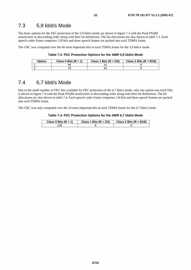
ETSI
ETSI TR 101 977 V1.1.1 (2001-07)22
7.3 5,9 kbit/s ModeThe basic options for the FEC protection of the 5,9 kbit/s mode are shown in figure 7.3 with the Peak PSQMsensitivities in descending order along with their bit definitions. The bit allocations are also shown in table 7.3. Eachspeech coder frame comprises 118 bits and three speech frames are packed into each TDMA frame.
The CRC was computed over the 60 most important bits in each TDMA frame for the 5,9 kbit/s mode.
Table 7.3: FEC Protection Options for the AMR 5,9 kbit/s Mode
Option Class 0 Bits (R = 1) Class 1 Bits (R = 2/3) Class 2 Bits (R = 8/18)1 96 14 82 78 40 0
7.4 6,7 kbit/s ModeDue to the small number of FEC bits available for FEC protection of the 6,7 kbit/s mode, only one option was tried Thisis shown in figure 7.4 with the Peak PSQM sensitivities in descending order along with their bit definitions. The bitallocations are also shown in table 7.4. Each speech coder frame comprises 134 bits and three speech frames are packedinto each TDMA frame.
The CRC was only computed over the 24 most important bits in each TDMA frame for the 6,7 kbit/s mode.
Table 7.4: FEC Protection Options for the AMR 6,7 kbit/s Mode
Class 0 Bits (R = 1) Class 1 Bits (R = 2/3) Class 2 Bits (R = 8/18)126 8 0

ETSI
ETSI TR 101 977 V1.1.1 (2001-07)23
0
2
4
6
8
10
12
14
LSF
V1
b7LS
FV
1b6
LSF
V1
b5LS
FV
1b4
LSF
V1
b3LS
FV
1b2
LSF
V1
b1LS
FV
1b0
LSF
V2
b7LS
FV
2b6
LSF
V2
b5LS
FV
2b4
LSF
V2
b3LS
FV
2b2
LSF
V2
b1LS
FV
2b0
SF
1A
CB
Indx
b5S
F1
AC
BIn
dxb4
SF
1A
CB
Indx
b3S
F1
AC
BIn
dxb6
SF
2A
CB
Indx
b3S
F2
AC
BIn
dxb2
SF
3A
CB
Indx
b3S
F1
AC
BIn
dxb7
SF
3A
CB
Indx
b2S
F1
AC
BIn
dxb2
SF
4A
CB
Indx
b3S
F4
AC
BIn
dxb2
SF
1A
CB
Indx
b1S
F2
AC
BIn
dxb1
SF
1&
2G
ains
b0S
F3
&4
Gai
nsb0
SF
1&
2G
ains
b1S
F3
&4
Gai
nsb1
SF
1&
2G
ains
b2S
F3
&4
Gai
nsb2
SF
3A
CB
Indx
b1S
F1
AC
BIn
dxb0
SF
2A
CB
Indx
b0LS
FV
3b6
LSF
V3
b5LS
FV
3b4
LSF
V3
b3LS
FV
3b2
LSF
V3
b1LS
FV
3b0
SF
1&
2G
ains
b3S
F3
&4
Gai
nsb3
SF
1P
ulse
2S
ign
SF
1P
ulse
1S
ign
SF
2P
ulse
2S
ign
SF
2P
ulse
1S
ign
SF
3P
ulse
2S
ign
SF
3P
ulse
1S
ign
SF
4P
ulse
2S
ign
SF
4P
ulse
1S
ign
SF
3A
CB
Indx
b0S
F4
AC
BIn
dxb1
SF
1&
2G
ains
b7S
F3
&4
Gai
nsb7
SF
1&
2G
ains
b4S
F3
&4
Gai
nsb4
SF
1&
2G
ains
b6S
F3
&4
Gai
nsb6
SF
1P
ulse
2P
osb0
SF
1P
ulse
1P
osb0
SF
2P
ulse
2P
osb0
SF
2P
ulse
1P
osb0
SF
3P
ulse
2P
osb0
SF
3P
ulse
1P
osb0
SF
4P
ulse
2P
osb0
SF
4P
ulse
1P
osb0
SF
1&
2G
ains
b5S
F3
&4
Gai
nsb5
SF
1P
ulse
2P
osb1
SF
1P
ulse
1P
osb1
SF
2P
ulse
2P
osb1
SF
2P
ulse
1P
osb1
SF
3P
ulse
2P
osb1
SF
3P
ulse
1P
osb1
SF
4P
ulse
2P
osb1
SF
4P
ulse
1P
osb1
SF
1P
ulse
2P
osb2
SF
1P
ulse
1P
osb2
SF
2P
ulse
2P
osb2
SF
2P
ulse
1P
osb2
SF
3P
ulse
2P
osb2
SF
3P
ulse
1P
osb2
SF
4P
ulse
2P
osb2
SF
4P
ulse
1P
osb2
SF
4A
CB
Indx
b0S
F1
Pos
nS
ubse
tS
F2
Pos
nS
ubse
tS
F3
Pos
nS
ubse
tS
F4
Pos
nS
ubse
t
Pk
PS
QM
0
0.5
1
1.5
2
2.5
Cla
ss
Figure 7.1: Ordered PeakPSQM and Bit Definition With Potential Protection Class for the 3GPP/GSM AMR 4,75 kbit/s Mode in 10 % Random Bit Errors

ETSI
ETSI TR 101 977 V1.1.1 (2001-07)24
0
2
4
6
8
10
12
14
LSF
V1
b7LS
FV
1b6
LSF
V1
b5LS
FV
1b4
LSF
V1
b3LS
FV
1b2
LSF
V1
b1LS
FV
1b0
LSF
V2
b7LS
FV
2b6
LSF
V2
b5LS
FV
2b4
LSF
V2
b3LS
FV
2b2
LSF
V2
b1LS
FV
2b0
SF
1A
CB
Indx
b5S
F1
AC
BIn
dxb4
SF
1A
CB
Indx
b3S
F2
AC
BIn
dxb3
SF
1A
CB
Indx
b6S
F3
AC
BIn
dxb3
SF
2A
CB
Indx
b2S
F1
AC
BIn
dxb7
SF
1A
CB
Indx
b2S
F3
AC
BIn
dxb2
SF
4A
CB
Indx
b3S
F4
AC
BIn
dxb2
SF
2A
CB
Indx
b1S
F1
AC
BIn
dxb1
SF
3A
CB
Indx
b1S
F1
Gai
nsb0
SF
2G
ains
b0S
F3
Gai
nsb0
SF
4G
ains
b0S
F2
AC
BIn
dxb0
SF
1A
CB
Indx
b0LS
FV
3b6
LSF
V3
b5LS
FV
3b4
LSF
V3
b3LS
FV
3b2
LSF
V3
b1LS
FV
3b0
SF
1P
ulse
2S
ign
SF
1P
ulse
1S
ign
SF
2P
ulse
2S
ign
SF
2P
ulse
1S
ign
SF
3P
ulse
2S
ign
SF
3P
ulse
1S
ign
SF
4P
ulse
2S
ign
SF
4P
ulse
1S
ign
SF
3A
CB
Indx
b0S
F4
AC
BIn
dxb1
SF
1G
ains
b1S
F2
Gai
nsb1
SF
3G
ains
b1S
F4
Gai
nsb1
SF
1P
ulse
2P
osb0
SF
1P
ulse
1P
osb0
SF
2P
ulse
2P
osb0
SF
2P
ulse
1P
osb0
SF
3P
ulse
2P
osb0
SF
3P
ulse
1P
osb0
SF
4P
ulse
2P
osb0
SF
4P
ulse
1P
osb0
SF
1P
ulse
2P
osb1
SF
1P
ulse
1P
osb1
SF
2P
ulse
2P
osb1
SF
2P
ulse
1P
osb1
SF
3P
ulse
2P
osb1
SF
3P
ulse
1P
osb1
SF
4P
ulse
2P
osb1
SF
4P
ulse
1P
osb1
SF
1P
ulse
2P
osb2
SF
1P
ulse
1P
osb2
SF
2P
ulse
2P
osb2
SF
2P
ulse
1P
osb2
SF
3P
ulse
2P
osb2
SF
3P
ulse
1P
osb2
SF
4P
ulse
2P
osb2
SF
4P
ulse
1P
osb2
SF
1P
osn
Sub
set
SF
2P
osn
Sub
set
SF
3P
osn
Sub
set
SF
4P
osn
Sub
set
SF
1G
ains
b2S
F2
Gai
nsb2
SF
3G
ains
b2S
F4
Gai
nsb2
SF
4A
CB
Indx
b0S
F1
Gai
nsb3
SF
2G
ains
b3S
F3
Gai
nsb3
SF
4G
ains
b3S
F1
Gai
nsb4
SF
2G
ains
b4S
F3
Gai
nsb4
SF
4G
ains
b4S
F1
Gai
nsb5
SF
2G
ains
b5S
F3
Gai
nsb5
SF
4G
ains
b5
Pk
PS
QM
0
0.5
1
1.5
2
2.5
Cla
ss
Figure 7.2: Ordered PeakPSQM and Bit Definition With Potential Protection Class for the 3GPP/GSM AMR 5,15 kbit/s Mode in 10 % Random Bit Errors

ETSI
ETSI TR 101 977 V1.1.1 (2001-07)25
0
2
4
6
8
10
12
14
LSF
V1
b7LS
FV
1b6
LSF
V1
b5LS
FV
1b4
LSF
V1
b3LS
FV
1b2
LSF
V1
b1LS
FV
1b0
LSF
V2
b8LS
FV
2b7
LSF
V2
b6LS
FV
2b5
LSF
V2
b4LS
FV
2b3
LSF
V2
b2LS
FV
2b1
LSF
V2
b0S
F1
AC
BIn
dxb4
SF
3A
CB
Indx
b4S
F1
AC
BIn
dxb5
SF
3A
CB
Indx
b5S
F1
AC
BIn
dxb3
SF
3A
CB
Indx
b3S
F1
AC
BIn
dxb6
SF
3A
CB
Indx
b6S
F1
AC
BIn
dxb7
SF
3A
CB
Indx
b7S
F2
AC
BIn
dxb3
SF
4A
CB
Indx
b3S
F2
AC
BIn
dxb2
SF
4A
CB
Indx
b2S
F1
AC
BIn
dxb2
SF
3A
CB
Indx
b2S
F1
AC
BIn
dxb1
SF
3A
CB
Indx
b1LS
FV
3b8
LSF
V3
b7LS
FV
3b6
LSF
V3
b5LS
FV
3b4
LSF
V3
b3LS
FV
3b2
LSF
V3
b1LS
FV
3b0
SF
1G
ains
b0S
F2
Gai
nsb0
SF
3G
ains
b0S
F4
Gai
nsb0
SF
2A
CB
Indx
b1S
F4
AC
BIn
dxb1
SF
1P
ulse
2S
ign
SF
2P
ulse
2S
ign
SF
3P
ulse
2S
ign
SF
4P
ulse
2S
ign
SF
1A
CB
Indx
b0S
F3
AC
BIn
dxb0
SF
1P
ulse
2P
osb4
SF
2P
ulse
2P
osb4
SF
3P
ulse
2P
osb4
SF
4P
ulse
2P
osb4
SF
1P
ulse
1S
ign
SF
2P
ulse
1S
ign
SF
3P
ulse
1S
ign
SF
4P
ulse
1S
ign
SF
1P
ulse
2P
osb3
SF
2P
ulse
2P
osb3
SF
3P
ulse
2P
osb3
SF
4P
ulse
2P
osb3
SF
1P
ulse
2P
osb1
SF
2P
ulse
2P
osb1
SF
3P
ulse
2P
osb1
SF
4P
ulse
2P
osb1
SF
1P
ulse
2P
osb0
SF
2P
ulse
2P
osb0
SF
3P
ulse
2P
osb0
SF
4P
ulse
2P
osb0
SF
1P
ulse
2P
osb2
SF
2P
ulse
2P
osb2
SF
3P
ulse
2P
osb2
SF
4P
ulse
2P
osb2
SF
1P
ulse
1P
osb3
SF
2P
ulse
1P
osb3
SF
3P
ulse
1P
osb3
SF
4P
ulse
1P
osb3
SF
1P
ulse
1P
osb0
SF
2P
ulse
1P
osb0
SF
3P
ulse
1P
osb0
SF
4P
ulse
1P
osb0
SF
1P
ulse
1P
osb1
SF
2P
ulse
1P
osb1
SF
3P
ulse
1P
osb1
SF
4P
ulse
1P
osb1
SF
1G
ains
b4S
F2
Gai
nsb4
SF
3G
ains
b4S
F4
Gai
nsb4
SF
1P
ulse
1P
osb2
SF
2P
ulse
1P
osb2
SF
3P
ulse
1P
osb2
SF
4P
ulse
1P
osb2
SF
1G
ains
b1S
F2
Gai
nsb1
SF
3G
ains
b1S
F4
Gai
nsb1
SF
1G
ains
b5S
F2
Gai
nsb5
SF
3G
ains
b5S
F4
Gai
nsb5
SF
2A
CB
Indx
b0S
F4
AC
BIn
dxb0
SF
1G
ains
b2S
F2
Gai
nsb2
SF
3G
ains
b2S
F4
Gai
nsb2
SF
1G
ains
b3S
F2
Gai
nsb3
SF
3G
ains
b3S
F4
Gai
nsb3
Pk
PS
QM
0
0.5
1
1.5
2
2.5
Cla
ss
Figure 7.3: Ordered PeakPSQM and Bit Definition With Potential Protection Class for the 3GPP/GSM AMR 5,9 kbit/s Mode in 10 % Random Bit Errors

ETSI
ETSI TR 101 977 V1.1.1 (2001-07)26
0
2
4
6
8
10
12
14
LSF
V1
b7LS
FV
1b6
LSF
V1
b5LS
FV
1b4
LSF
V1
b3LS
FV
1b2
LSF
V1
b1LS
FV
1b0
LSF
V2
b8LS
FV
2b7
LSF
V2
b6LS
FV
2b5
LSF
V2
b4LS
FV
2b3
LSF
V2
b2LS
FV
2b1
LSF
V2
b0S
F1
AC
BIn
dxb5
SF
3A
CB
Indx
b5S
F1
AC
BIn
dxb4
SF
3A
CB
Indx
b4S
F1
AC
BIn
dxb6
SF
3A
CB
Indx
b6S
F1
AC
BIn
dxb3
SF
3A
CB
Indx
b3S
F1
AC
BIn
dxb7
SF
3A
CB
Indx
b7S
F2
AC
BIn
dxb3
SF
4A
CB
Indx
b3S
F1
AC
BIn
dxb2
SF
3A
CB
Indx
b2S
F2
AC
BIn
dxb2
SF
4A
CB
Indx
b2S
F1
AC
BIn
dxb1
SF
3A
CB
Indx
b1S
F1
Gai
nsb6
SF
2G
ains
b6S
F3
Gai
nsb6
SF
4G
ains
b6LS
FV
3b8
LSF
V3
b7LS
FV
3b6
LSF
V3
b5LS
FV
3b4
LSF
V3
b3LS
FV
3b2
LSF
V3
b1LS
FV
3b0
SF
2A
CB
Indx
b1S
F4
AC
BIn
dxb1
SF
1A
CB
Indx
b0S
F3
AC
BIn
dxb0
SF
1P
ulse
3S
ign
SF
2P
ulse
3S
ign
SF
3P
ulse
3S
ign
SF
4P
ulse
3S
ign
SF
1P
ulse
2S
ign
SF
2P
ulse
2S
ign
SF
3P
ulse
2S
ign
SF
4P
ulse
2S
ign
SF
1P
ulse
1S
ign
SF
2P
ulse
1S
ign
SF
3P
ulse
1S
ign
SF
4P
ulse
1S
ign
SF
1G
ains
b3S
F2
Gai
nsb3
SF
3G
ains
b3S
F4
Gai
nsb3
SF
2A
CB
Indx
b0S
F4
AC
BIn
dxb0
SF
1P
ulse
3P
osb2
SF
2P
ulse
3P
osb2
SF
3P
ulse
3P
osb2
SF
4P
ulse
3P
osb2
SF
1P
ulse
2P
osb1
SF
2P
ulse
2P
osb1
SF
3P
ulse
2P
osb1
SF
4P
ulse
2P
osb1
SF
1G
ains
b2S
F2
Gai
nsb2
SF
3G
ains
b2S
F4
Gai
nsb2
SF
1P
ulse
2P
osb0
SF
2P
ulse
2P
osb0
SF
3P
ulse
2P
osb0
SF
4P
ulse
2P
osb0
SF
1P
ulse
1P
osb0
SF
2P
ulse
1P
osb0
SF
3P
ulse
1P
osb0
SF
4P
ulse
1P
osb0
SF
1P
ulse
1P
osb1
SF
2P
ulse
1P
osb1
SF
3P
ulse
1P
osb1
SF
4P
ulse
1P
osb1
SF
1P
ulse
3P
osb1
SF
2P
ulse
3P
osb1
SF
3P
ulse
3P
osb1
SF
4P
ulse
3P
osb1
SF
1P
ulse
3P
osb0
SF
2P
ulse
3P
osb0
SF
3P
ulse
3P
osb0
SF
4P
ulse
3P
osb0
SF
1P
ulse
2P
osb2
SF
2P
ulse
2P
osb2
SF
3P
ulse
2P
osb2
SF
4P
ulse
2P
osb2
SF
1P
ulse
1P
osb2
SF
2P
ulse
1P
osb2
SF
3P
ulse
1P
osb2
SF
4P
ulse
1P
osb2
SF
1G
ains
b5S
F2
Gai
nsb5
SF
3G
ains
b5S
F4
Gai
nsb5
SF
1P
ulse
3P
osb3
SF
2P
ulse
3P
osb3
SF
3P
ulse
3P
osb3
SF
4P
ulse
3P
osb3
SF
1P
ulse
2P
osb3
SF
2P
ulse
2P
osb3
SF
3P
ulse
2P
osb3
SF
4P
ulse
2P
osb3
SF
1G
ains
b1S
F2
Gai
nsb1
SF
3G
ains
b1S
F4
Gai
nsb1
SF
1G
ains
b4S
F2
Gai
nsb4
SF
3G
ains
b4S
F4
Gai
nsb4
SF
1G
ains
b0S
F2
Gai
nsb0
SF
3G
ains
b0S
F4
Gai
nsb0
Pk
PS
QM
0
0.5
1
1.5
2
2.5
Cla
ss
Figure 7.4: Ordered PeakPSQM and Bit Definition With Potential Protection Class for the 3GPP/GSM AMR 6,7 kbit/s Mode in 10 % Random Bit Errors

ETSI
ETSI TR 101 977 V1.1.1 (2001-07)27
8 Coverage Performance of the FEC SchemesAccording to four different channel conditions (Static, TU5, TU50 and HT200), and various C/I conditions, 'soft'channel errors were simulated using a TETRA MODEM and channel simulation package and applied to the FECencoded data streams prior to FEC decoding and speech was synthesized. Each synthesized speech file was comparedusing ITU-T Recommendation P.861 [1] to the appropriate error-free speech and both the PSQM and Peak-PSQMvalues obtained. The FEC options, identified in clause 7, for each 3GPP/GSM AMR Mode were compared.
8.1 4,75 kbit/s ModeThe results for the four options of FEC for the 4,75 kbit/s mode are shown in figures 8.1 to 8.8. Figures 8.1 and 8.2 areapplicable to the static channel, figures 8.3 and 8.4 are applicable to the TU5 channel, figures 8.5 and 8.6 are applicableto the TU50 channel and figures 8.7 and 8.8 are applicable to the HT200 channel.
When compared to the performance of the TETRA speech codec, it is clear that there is a trade-off betweenperformance according to the PSQM and the Peak PSQM metrics. Of the four possible FEC options, the method whichappears to provide performance most similar to that of the TETRA codec is Option 3.
Figures 8.1 and 8.2 appear to show the PSQM decreasing with C/I for very poor channels. This effect appears to resultsfrom the muting of frames during severe channel conditions and is not significant.
The TU5 channel clearly appears to vary too slowly for meaningful statistics of the Peak PSQM measure to be obtained.
8.2 5,15 kbit/s ModeThe results for the four options of FEC for the 5,15 kbit/s mode are shown in figures 8.9 to 8.16.
As for the 4,75 kbit/s mode, there is a clear trade-off between performance according to the PSQM and the Peak PSQMmetrics. Of the four possible FEC options, the method which appears to provide the best balance of performance isOption 3.
As for the 4,75 kbit/s mode, figures 8.9 and 8.10 appear to show the PSQM decreasing with C/I for very poor channels.Again, the TU5 channel clearly appears to vary too slowly for meaningful statistics of the Peak PSQM measure to beobtained.
8.3 5,9 kbit/s ModeThe results for the two options of FEC for the 5,9 kbit/s mode are shown in figures 8.17 to 8.24.
The trade-off between PSQM and the Peak PSQM metric performance is again clear. Of the FEC options considered,the method which appears to provide the best balance of performance is Option 2.
8.4 6,7 kbit/s ModeThe results for the FEC of the 6,7 kbit/s mode are shown in figures 8.25 to 8.32.
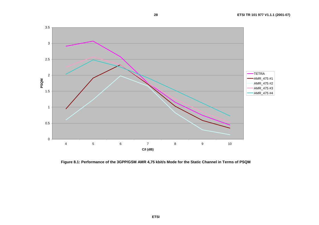
ETSI
ETSI TR 101 977 V1.1.1 (2001-07)28
0
0.5
1
1.5
2
2.5
3
3.5
4 5 6 7 8 9 10
C/I (dB)
PS
QM
TETRA
AMR_475 #1
AMR_475 #2
AMR_475 #3
AMR_475 #4
Figure 8.1: Performance of the 3GPP/GSM AMR 4,75 kbit/s Mode for the Static Channel in Terms of PSQM
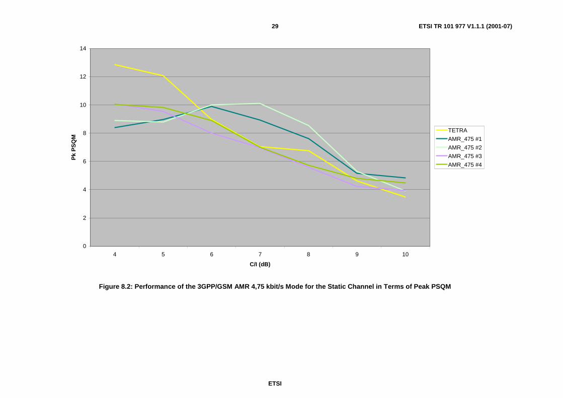
ETSI
ETSI TR 101 977 V1.1.1 (2001-07)29
0
2
4
6
8
10
12
14
4 5 6 7 8 9 10
C/I (dB)
Pk
PS
QM
TETRA
AMR_475 #1
AMR_475 #2
AMR_475 #3
AMR_475 #4
Figure 8.2: Performance of the 3GPP/GSM AMR 4,75 kbit/s Mode for the Static Channel in Terms of Peak PSQM

ETSI
ETSI TR 101 977 V1.1.1 (2001-07)30
0
0.1
0.2
0.3
0.4
0.5
0.6
0.7
0.8
0.9
10 12 14 16 18 20 22 24
C/I (dB)
PS
QM
TETRA
AMR_475 #1
AMR_475 #2
AMR_475 #3
AMR_475 #4
Figure 8.3: Performance of the 3GPP/GSM AMR 4,75 kbit/s Mode for the TU5 Channel in Terms of PSQM
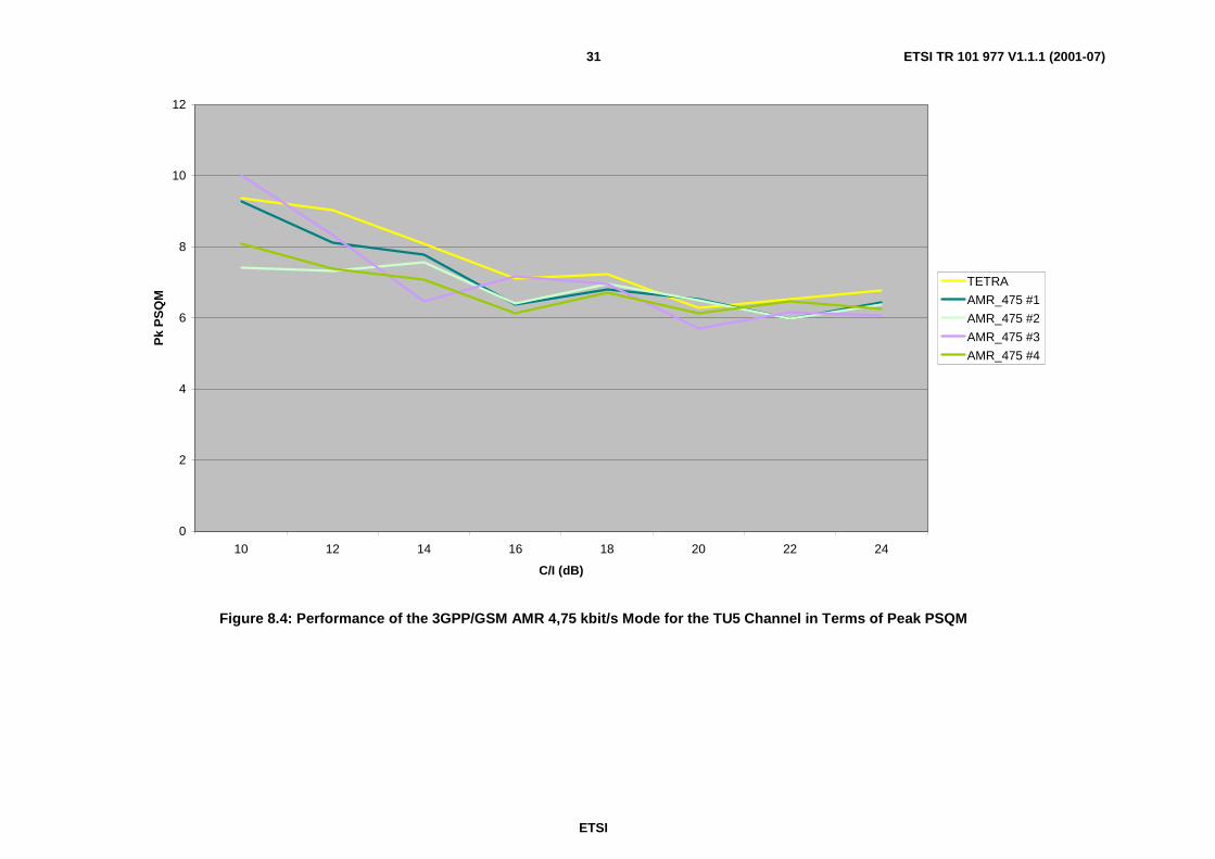
ETSI
ETSI TR 101 977 V1.1.1 (2001-07)31
0
2
4
6
8
10
12
10 12 14 16 18 20 22 24
C/I (dB)
Pk
PS
QM
TETRA
AMR_475 #1
AMR_475 #2
AMR_475 #3
AMR_475 #4
Figure 8.4: Performance of the 3GPP/GSM AMR 4,75 kbit/s Mode for the TU5 Channel in Terms of Peak PSQM

ETSI
ETSI TR 101 977 V1.1.1 (2001-07)32
0
0.2
0.4
0.6
0.8
1
1.2
1.4
1.6
1.8
2
10 12 14 16 18 20 22 24
C/I (dB)
PS
QM
TETRA
AMR_475 #1
AMR_475 #2
AMR_475 #3
AMR_475 #4
Figure 8.5: Performance of the 3GPP/GSM AMR 4,75 kbit/s Mode for the TU50 Channel in Terms of PSQM
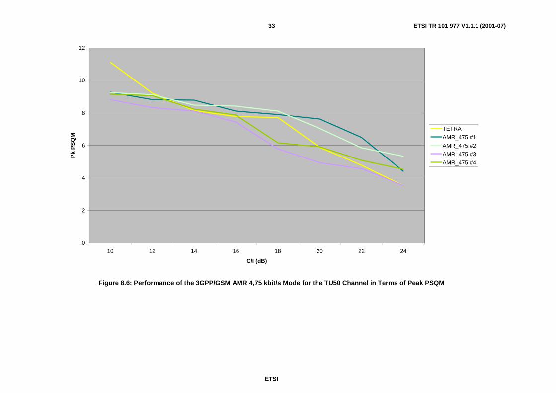
ETSI
ETSI TR 101 977 V1.1.1 (2001-07)33
0
2
4
6
8
10
12
10 12 14 16 18 20 22 24
C/I (dB)
Pk
PS
QM
TETRA
AMR_475 #1
AMR_475 #2
AMR_475 #3
AMR_475 #4
Figure 8.6: Performance of the 3GPP/GSM AMR 4,75 kbit/s Mode for the TU50 Channel in Terms of Peak PSQM
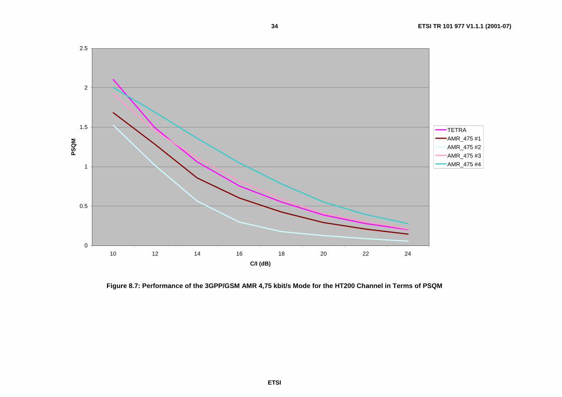
ETSI
ETSI TR 101 977 V1.1.1 (2001-07)34
0
0.5
1
1.5
2
2.5
10 12 14 16 18 20 22 24
C/I (dB)
PS
QM
TETRA
AMR_475 #1
AMR_475 #2
AMR_475 #3
AMR_475 #4
Figure 8.7: Performance of the 3GPP/GSM AMR 4,75 kbit/s Mode for the HT200 Channel in Terms of PSQM

ETSI
ETSI TR 101 977 V1.1.1 (2001-07)35
0
2
4
6
8
10
12
10 12 14 16 18 20 22 24
C/I (dB)
Pk
PS
QM
TETRA
AMR_475 #1
AMR_475 #2
AMR_475 #3
AMR_475 #4
Figure 8.8: Performance of the 3GPP/GSM AMR 4,75 kbit/s Mode for the HT200 Channel in Terms of Peak PSQM

ETSI
ETSI TR 101 977 V1.1.1 (2001-07)36
0
0.5
1
1.5
2
2.5
3
3.5
4 5 6 7 8 9 10
C/I (dB)
PS
QM
TETRA
AMR_515 #1
AMR_515 #2
AMR_515 #3
AMR_515 #4
Figure 8.9: Performance of the 3GPP/GSM AMR 5,15 kbit/s Mode for the Static Channel in Terms of PSQM

ETSI
ETSI TR 101 977 V1.1.1 (2001-07)37
0
2
4
6
8
10
12
14
4 5 6 7 8 9 10
C/I (dB)
Pk
PS
QM
TETRA
AMR_515 #1
AMR_515 #2
AMR_515 #3
AMR_515 #4
Figure 8.10: Performance of the 3GPP/GSM AMR 5,15 kbit/s Mode for the Static Channel in Terms of Peak PSQM

ETSI
ETSI TR 101 977 V1.1.1 (2001-07)38
0
0.1
0.2
0.3
0.4
0.5
0.6
0.7
0.8
0.9
1
10 12 14 16 18 20 22 24
C/I (dB)
PS
QM
TETRA
AMR_515 #1
AMR_515 #2
AMR_515 #3
AMR_515 #4
Figure 8.11: Performance of the 3GPP/GSM AMR 5,15 kbit/s Mode for the TU5 Channel in Terms of PSQM
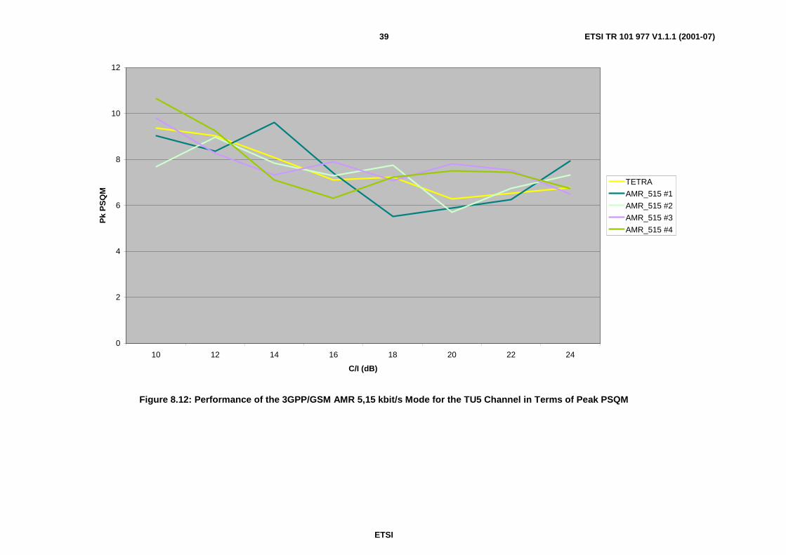
ETSI
ETSI TR 101 977 V1.1.1 (2001-07)39
0
2
4
6
8
10
12
10 12 14 16 18 20 22 24
C/I (dB)
Pk
PS
QM
TETRA
AMR_515 #1
AMR_515 #2
AMR_515 #3
AMR_515 #4
Figure 8.12: Performance of the 3GPP/GSM AMR 5,15 kbit/s Mode for the TU5 Channel in Terms of Peak PSQM
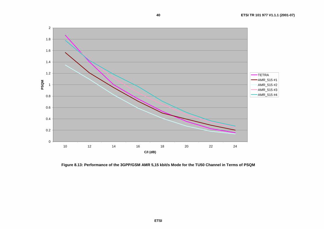
ETSI
ETSI TR 101 977 V1.1.1 (2001-07)40
0
0.2
0.4
0.6
0.8
1
1.2
1.4
1.6
1.8
2
10 12 14 16 18 20 22 24
C/I (dB)
PS
QM
TETRA
AMR_515 #1
AMR_515 #2
AMR_515 #3
AMR_515 #4
Figure 8.13: Performance of the 3GPP/GSM AMR 5,15 kbit/s Mode for the TU50 Channel in Terms of PSQM

ETSI
ETSI TR 101 977 V1.1.1 (2001-07)41
0
2
4
6
8
10
12
10 12 14 16 18 20 22 24
C/I (dB)
Pk
PS
QM
TETRA
AMR_515 #1
AMR_515 #2
AMR_515 #3
AMR_515 #4
Figure 8.14: Performance of the 3GPP/GSM AMR 5,15 kbit/s Mode for the TU50 Channel in Terms of Peak PSQM

ETSI
ETSI TR 101 977 V1.1.1 (2001-07)42
0
0.5
1
1.5
2
2.5
10 12 14 16 18 20 22 24
C/I (dB)
PS
QM
TETRA
AMR_515 #1
AMR_515 #2
AMR_515 #3
AMR_515 #4
Figure 8.15: Performance of the 3GPP/GSM AMR 5,15 kbit/s Mode for the HT200 Channel in Terms of PSQM
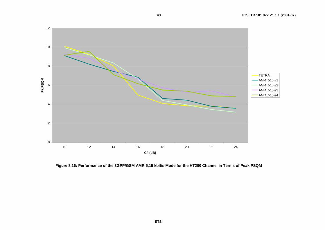
ETSI
ETSI TR 101 977 V1.1.1 (2001-07)43
0
2
4
6
8
10
12
10 12 14 16 18 20 22 24
C/I (dB)
Pk
PS
QM
TETRA
AMR_515 #1
AMR_515 #2
AMR_515 #3
AMR_515 #4
Figure 8.16: Performance of the 3GPP/GSM AMR 5,15 kbit/s Mode for the HT200 Channel in Terms of Peak PSQM
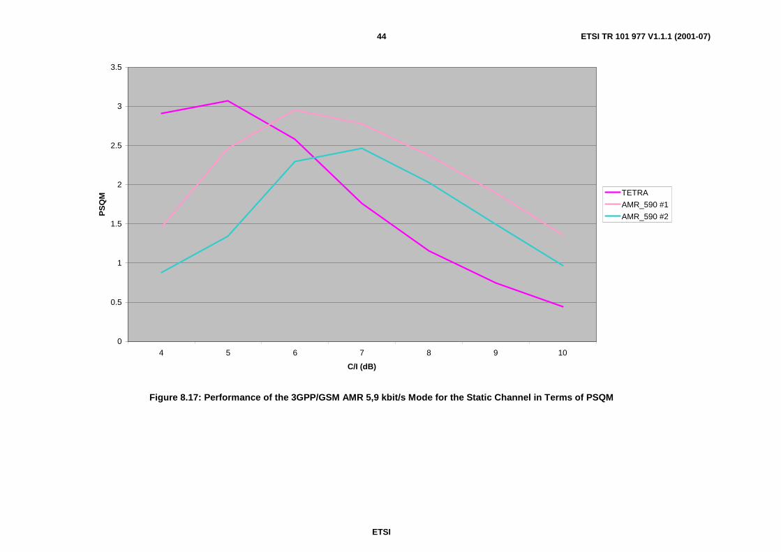
ETSI
ETSI TR 101 977 V1.1.1 (2001-07)44
0
0.5
1
1.5
2
2.5
3
3.5
4 5 6 7 8 9 10
C/I (dB)
PS
QM TETRA
AMR_590 #1
AMR_590 #2
Figure 8.17: Performance of the 3GPP/GSM AMR 5,9 kbit/s Mode for the Static Channel in Terms of PSQM

ETSI
ETSI TR 101 977 V1.1.1 (2001-07)45
0
2
4
6
8
10
12
14
4 5 6 7 8 9 10
C/I (dB)
Pk
PS
QM TETRA
AMR_590 #1
AMR_590 #2
Figure 8.18: Performance of the 3GPP/GSM AMR 5,9 kbit/s Mode for the Static Channel in Terms of Peak PSQM

ETSI
ETSI TR 101 977 V1.1.1 (2001-07)46
0
0.1
0.2
0.3
0.4
0.5
0.6
0.7
0.8
0.9
1
10 12 14 16 18 20 22 24
C/I (dB)
PS
QM TETRA
AMR_590 #1
AMR_590 #2
Figure 8.19: Performance of the 3GPP/GSM AMR 5,9 kbit/s Mode for the TU5 Channel in Terms of PSQM

ETSI
ETSI TR 101 977 V1.1.1 (2001-07)47
0
2
4
6
8
10
12
14
16
10 12 14 16 18 20 22 24
C/I (dB)
Pk
PS
QM TETRA
AMR_590 #1
AMR_590 #2
Figure 8.20: Performance of the 3GPP/GSM AMR 5,9 kbit/s Mode for the TU5 Channel in Terms of Peak PSQM
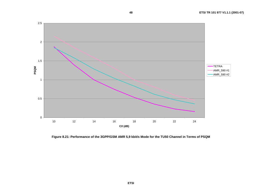
ETSI
ETSI TR 101 977 V1.1.1 (2001-07)48
0
0.5
1
1.5
2
2.5
10 12 14 16 18 20 22 24
C/I (dB)
PS
QM TETRA
AMR_590 #1
AMR_590 #2
Figure 8.21: Performance of the 3GPP/GSM AMR 5,9 kbit/s Mode for the TU50 Channel in Terms of PSQM

ETSI
ETSI TR 101 977 V1.1.1 (2001-07)49
0
2
4
6
8
10
12
10 12 14 16 18 20 22 24
C/I (dB)
Pk
PS
QM TETRA
AMR_590 #1
AMR_590 #2
Figure 8.22: Performance of the 3GPP/GSM AMR 5,9 kbit/s Mode for the TU50 Channel in Terms of Peak PSQM

ETSI
ETSI TR 101 977 V1.1.1 (2001-07)50
0
0.5
1
1.5
2
2.5
3
10 12 14 16 18 20 22 24
C/I (dB)
PS
QM TETRA
AMR_590 #1
AMR_590 #2
Figure 8.23: Performance of the 3GPP/GSM AMR 5,9 kbit/s Mode for the HT200 Channel in Terms of PSQM

ETSI
ETSI TR 101 977 V1.1.1 (2001-07)51
0
2
4
6
8
10
12
10 12 14 16 18 20 22 24
C/I (dB)
Pk
PS
QM TETRA
AMR_590 #1
AMR_590 #2
Figure 8.24: Performance of the 3GPP/GSM AMR 5,9 kbit/s Mode for the HT200 Channel in Terms of Peak PSQM
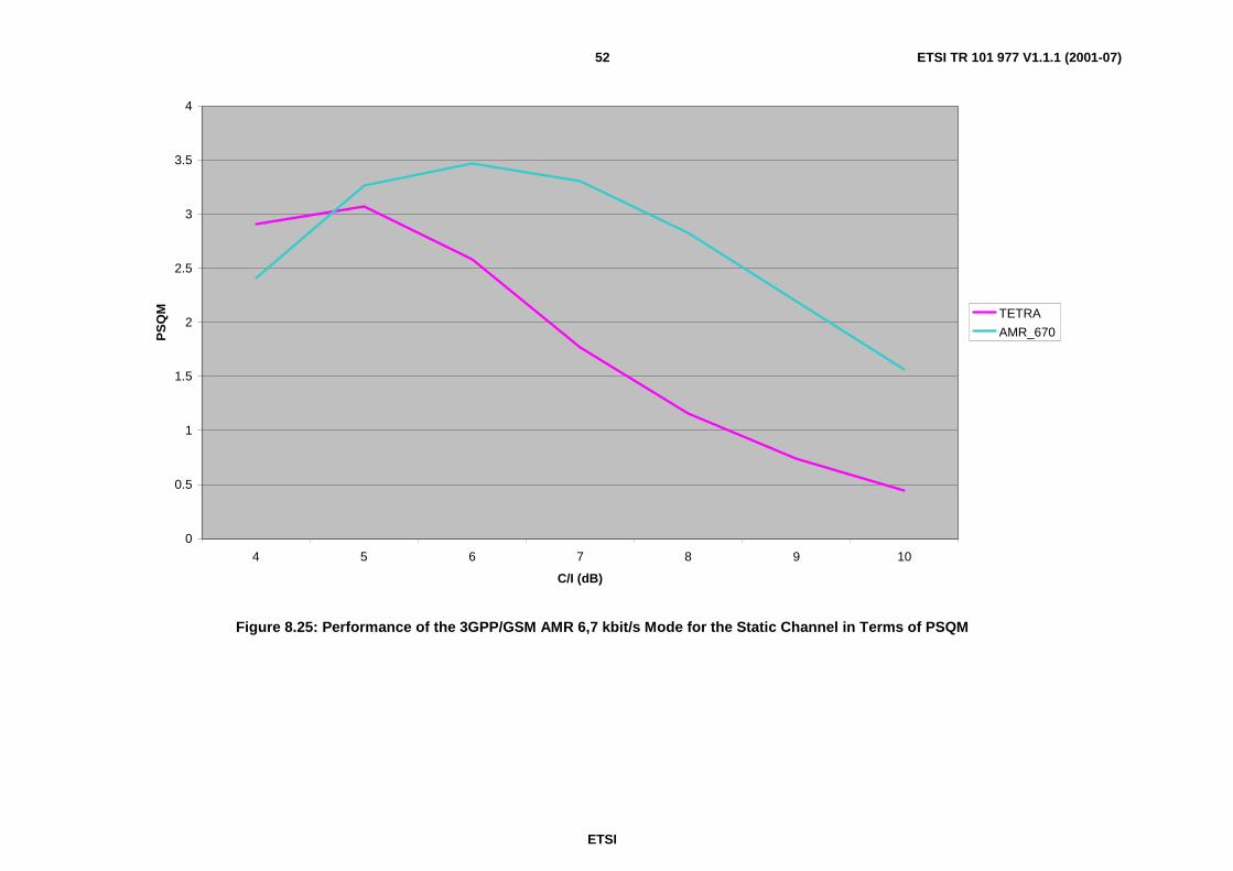
ETSI
ETSI TR 101 977 V1.1.1 (2001-07)52
0
0.5
1
1.5
2
2.5
3
3.5
4
4 5 6 7 8 9 10
C/I (dB)
PS
QM TETRA
AMR_670
Figure 8.25: Performance of the 3GPP/GSM AMR 6,7 kbit/s Mode for the Static Channel in Terms of PSQM

ETSI
ETSI TR 101 977 V1.1.1 (2001-07)53
0
2
4
6
8
10
12
14
4 5 6 7 8 9 10
C/I (dB)
Pk
PS
QM
TETRA
AMR_670
Figure 8.26: Performance of the 3GPP/GSM AMR 6,7 kbit/s Mode for the Static Channel in Terms of Peak PSQM
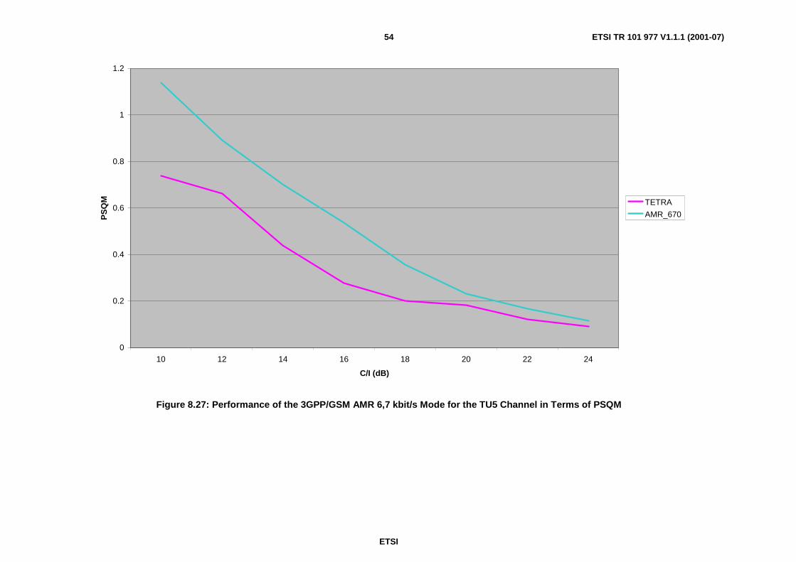
ETSI
ETSI TR 101 977 V1.1.1 (2001-07)54
0
0.2
0.4
0.6
0.8
1
1.2
10 12 14 16 18 20 22 24
C/I (dB)
PS
QM TETRA
AMR_670
Figure 8.27: Performance of the 3GPP/GSM AMR 6,7 kbit/s Mode for the TU5 Channel in Terms of PSQM

ETSI
ETSI TR 101 977 V1.1.1 (2001-07)55
0
2
4
6
8
10
12
10 12 14 16 18 20 22 24
C/I (dB)
Pk
PS
QM
TETRA
AMR_670
Figure 8.28: Performance of the 3GPP/GSM AMR 6,7 kbit/s Mode for the TU5 Channel in Terms of Peak PSQM
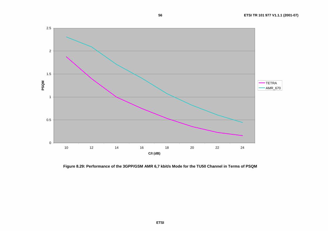
ETSI
ETSI TR 101 977 V1.1.1 (2001-07)56
0
0.5
1
1.5
2
2.5
10 12 14 16 18 20 22 24
C/I (dB)
PS
QM TETRA
AMR_670
Figure 8.29: Performance of the 3GPP/GSM AMR 6,7 kbit/s Mode for the TU50 Channel in Terms of PSQM
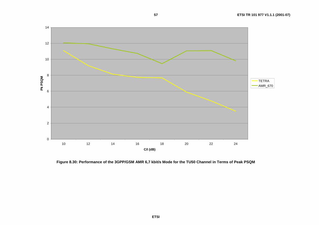
ETSI
ETSI TR 101 977 V1.1.1 (2001-07)57
0
2
4
6
8
10
12
14
10 12 14 16 18 20 22 24
C/I (dB)
Pk
PS
QM
TETRA
AMR_670
Figure 8.30: Performance of the 3GPP/GSM AMR 6,7 kbit/s Mode for the TU50 Channel in Terms of Peak PSQM

ETSI
ETSI TR 101 977 V1.1.1 (2001-07)58
0
0.5
1
1.5
2
2.5
3
3.5
10 12 14 16 18 20 22 24
C/I (dB)
PS
QM TETRA
AMR_670
Figure 8.31: Performance of the 3GPP/GSM AMR 6,7 kbit/s Mode for the HT200 Channel in Terms of PSQM
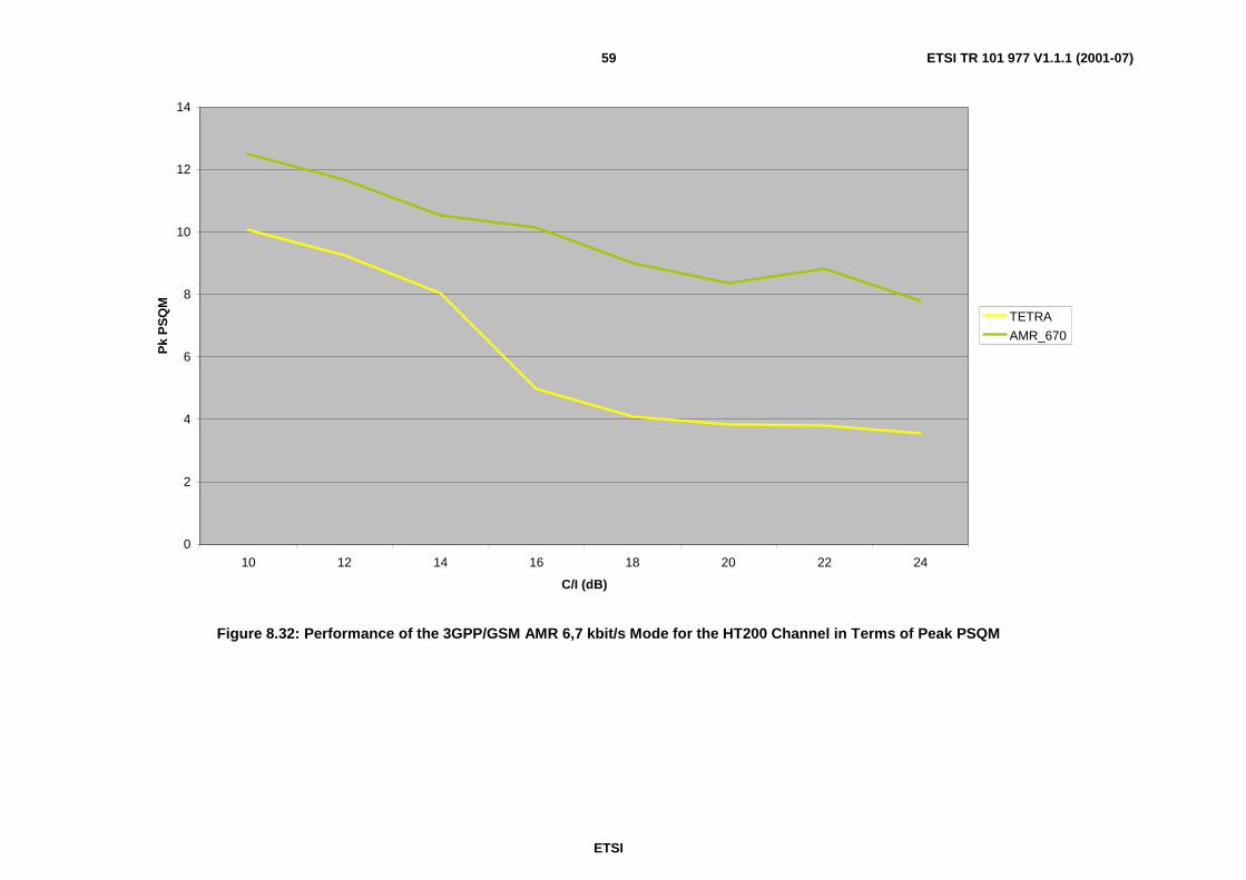
ETSI
ETSI TR 101 977 V1.1.1 (2001-07)59
0
2
4
6
8
10
12
14
10 12 14 16 18 20 22 24
C/I (dB)
Pk
PS
QM
TETRA
AMR_670
Figure 8.32: Performance of the 3GPP/GSM AMR 6,7 kbit/s Mode for the HT200 Channel in Terms of Peak PSQM

ETSI
ETSI TR 101 977 V1.1.1 (2001-07)60
8.5 Performance of the Selected FEC SchemesThe results of the comparing the error-free speech with the channel impaired speech usingITU-T Recommendation P.861 [1] for the selected FEC schemes for all modes are shown in figures 8.33 to 8.40.
The closeness of the performance of the 4,75 kbit/s mode and the TETRA Codec is apparent with little degradationacross all channel conditions for both the PSQM and Peak PSQM metrics.
There is a clear degradation of PSQM and Peak PSQM with bit rate in these figures. The 5,15 kbit/s mode is 1-2 dBworse than either TETRA or the 4,75 kbit/s mode. The 5,9 kbit/s mode is 2-4 dB worse than either TETRA or the4,75 kbit/s mode and the 6,7 kbit/s mode is 4-6 dB worse than TETRA or the 4,75 kbit/s mode.
An additional set of results was obtained by evaluating the ITU-T Recommendation P.861 [1] distortions with referenceto the unprocessed original speech (time-aligned). This resulted in the plots in figures 8.41 to 8.48 for the Peak-PSQMand PSQM scores. Ideally these figures should reflect the true apparent quality of the codec and FEC operatingtogether, under each channel condition.
The figures appear to show that the 4,75 kbit/s mode out-performs the TETRA Codec under all conditions, except the18dB C/I point for TU5 according to the Peak PSQM metric, where the difference is very small.
Over the range of C/I conditions tested and over the range of channel types, the 5,15 kbit/s mode appears to show littleconsistent performance improvement over the 4,75 kbit/s mode.
The 5,9 kbit/s and 6,7 kbit/s modes appear to demonstrate an improvement over the 4,75 kbit/s mode according to thePSQM metric for high C/I conditions, although in terms of the Peak PSQM metric, only the 5,9 kbit/s mode comesclose to matching the performance of the 4,75 kbit/s mode. This tends to suggest that the quality of the speech is marredby several large distortions, rather than a consistent low level of degradation which may prove to be disturbing tolisteners.
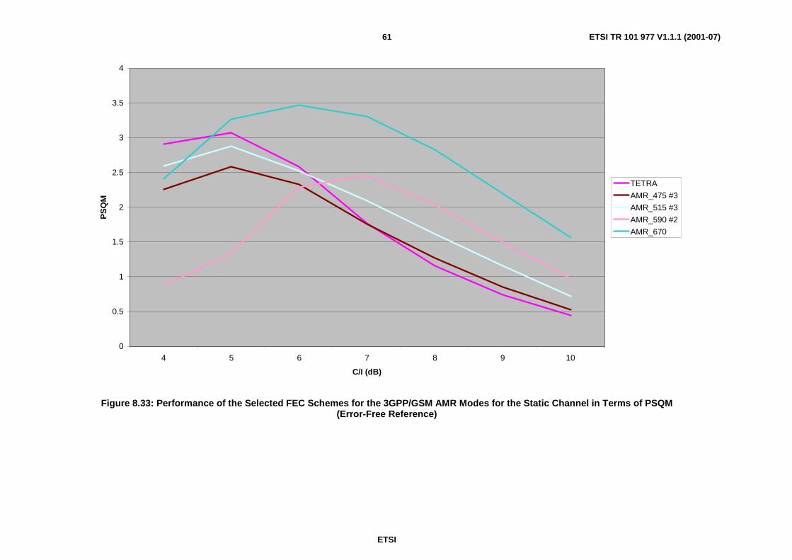
ETSI
ETSI TR 101 977 V1.1.1 (2001-07)61
0
0.5
1
1.5
2
2.5
3
3.5
4
4 5 6 7 8 9 10
C/I (dB)
PS
QM
TETRA
AMR_475 #3
AMR_515 #3
AMR_590 #2
AMR_670
Figure 8.33: Performance of the Selected FEC Schemes for the 3GPP/GSM AMR Modes for the Static Channel in Terms of PSQM(Error-Free Reference)

ETSI
ETSI TR 101 977 V1.1.1 (2001-07)62
0
2
4
6
8
10
12
14
4 5 6 7 8 9 10
C/I (dB)
Pk
PS
QM
TETRA
AMR_475 #3
AMR_515 #3
AMR_590 #2
AMR_670
Figure 8.34: Performance of the Selected FEC Schemes for the 3GPP/GSM AMR Modes for the Static Channel in Terms of Peak PSQM(Error-Free Reference)
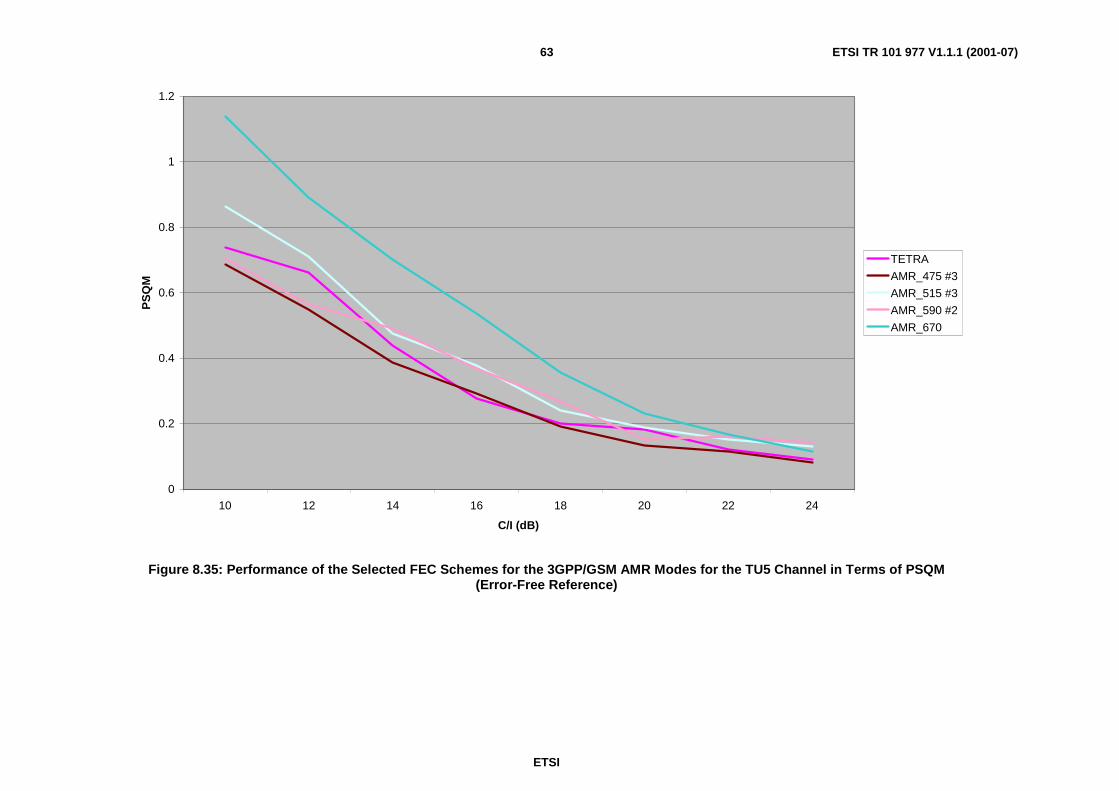
ETSI
ETSI TR 101 977 V1.1.1 (2001-07)63
0
0.2
0.4
0.6
0.8
1
1.2
10 12 14 16 18 20 22 24
C/I (dB)
PS
QM
TETRA
AMR_475 #3
AMR_515 #3
AMR_590 #2
AMR_670
Figure 8.35: Performance of the Selected FEC Schemes for the 3GPP/GSM AMR Modes for the TU5 Channel in Terms of PSQM(Error-Free Reference)

ETSI
ETSI TR 101 977 V1.1.1 (2001-07)64
0
2
4
6
8
10
12
14
16
10 12 14 16 18 20 22 24
C/I (dB)
Pk
PS
QM
TETRA
AMR_475 #3
AMR_515 #3
AMR_590 #2
AMR_670
Figure 8.36: Performance of the Selected FEC Schemes for the 3GPP/GSM AMR Modes for the TU5 Channel in Terms of Peak PSQM(Error-Free Reference)

ETSI
ETSI TR 101 977 V1.1.1 (2001-07)65
0
0.5
1
1.5
2
2.5
10 12 14 16 18 20 22 24
C/I (dB)
PS
QM
TETRA
AMR_475 #3
AMR_515 #3
AMR_590 #2
AMR_670
Figure 8.37: Performance of the Selected FEC Schemes for the 3GPP/GSM AMR Modes for the TU50 Channel in Terms of PSQM(Error-Free Reference)
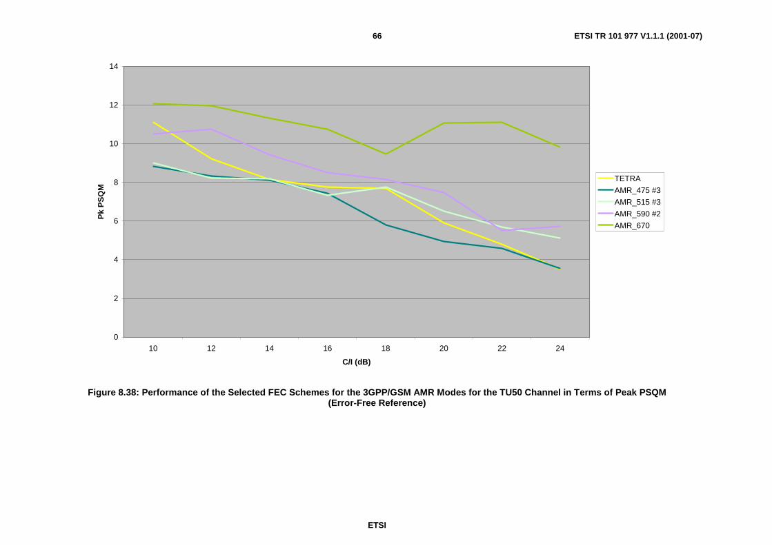
ETSI
ETSI TR 101 977 V1.1.1 (2001-07)66
0
2
4
6
8
10
12
14
10 12 14 16 18 20 22 24
C/I (dB)
Pk
PS
QM
TETRA
AMR_475 #3
AMR_515 #3
AMR_590 #2
AMR_670
Figure 8.38: Performance of the Selected FEC Schemes for the 3GPP/GSM AMR Modes for the TU50 Channel in Terms of Peak PSQM(Error-Free Reference)

ETSI
ETSI TR 101 977 V1.1.1 (2001-07)67
0
0.5
1
1.5
2
2.5
3
3.5
10 12 14 16 18 20 22 24
C/I (dB)
PS
QM
TETRA
AMR_475 #3
AMR_515 #3
AMR_590 #2
AMR_670
Figure 8.39: Performance of the Selected FEC Schemes for the 3GPP/GSM AMR Modes for the HT200 Channel in Terms of PSQM(Error-Free Reference)
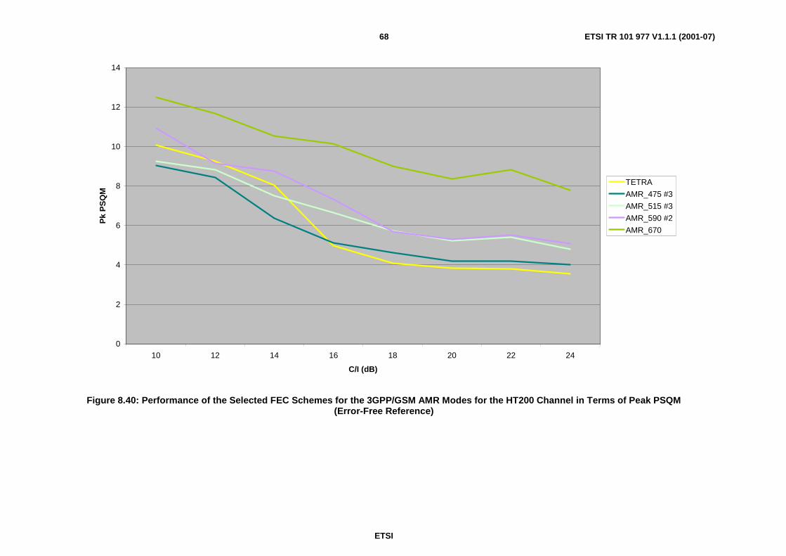
ETSI
ETSI TR 101 977 V1.1.1 (2001-07)68
0
2
4
6
8
10
12
14
10 12 14 16 18 20 22 24
C/I (dB)
Pk
PS
QM
TETRA
AMR_475 #3
AMR_515 #3
AMR_590 #2
AMR_670
Figure 8.40: Performance of the Selected FEC Schemes for the 3GPP/GSM AMR Modes for the HT200 Channel in Terms of Peak PSQM(Error-Free Reference)
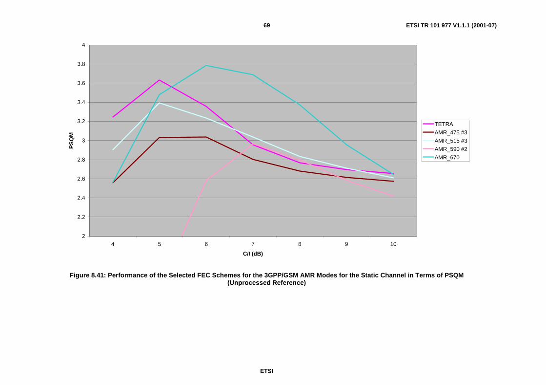
ETSI
ETSI TR 101 977 V1.1.1 (2001-07)69
2
2.2
2.4
2.6
2.8
3
3.2
3.4
3.6
3.8
4
4 5 6 7 8 9 10
C/I (dB)
PS
QM
TETRA
AMR_475 #3
AMR_515 #3
AMR_590 #2
AMR_670
Figure 8.41: Performance of the Selected FEC Schemes for the 3GPP/GSM AMR Modes for the Static Channel in Terms of PSQM(Unprocessed Reference)

ETSI
ETSI TR 101 977 V1.1.1 (2001-07)70
6
7
8
9
10
11
12
13
14
4 5 6 7 8 9 10
C/I (dB)
Pk
PS
QM
TETRA
AMR_475 #3
AMR_515 #3
AMR_590 #2
AMR_670
Figure 8.42: Performance of the Selected FEC Schemes for the 3GPP/GSM AMR Modes for the Static Channel in Terms of Peak PSQM(Unprocessed Reference)
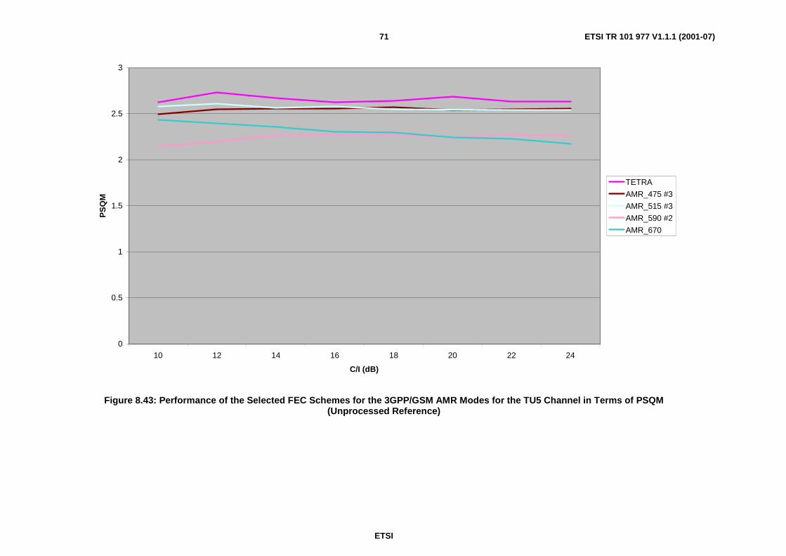
ETSI
ETSI TR 101 977 V1.1.1 (2001-07)71
0
0.5
1
1.5
2
2.5
3
10 12 14 16 18 20 22 24
C/I (dB)
PS
QM
TETRA
AMR_475 #3
AMR_515 #3
AMR_590 #2
AMR_670
Figure 8.43: Performance of the Selected FEC Schemes for the 3GPP/GSM AMR Modes for the TU5 Channel in Terms of PSQM(Unprocessed Reference)

ETSI
ETSI TR 101 977 V1.1.1 (2001-07)72
6
7
8
9
10
11
12
13
14
10 12 14 16 18 20 22 24
C/I (dB)
Pk
PS
QM
TETRA
AMR_475 #3
AMR_515 #3
AMR_590 #2
AMR_670
Figure 8.44: Performance of the Selected FEC Schemes for the 3GPP/GSM AMR Modes for the TU5 Channel in Terms of Peak PSQM(Unprocessed Reference)

ETSI
ETSI TR 101 977 V1.1.1 (2001-07)73
2
2.2
2.4
2.6
2.8
3
3.2
10 12 14 16 18 20 22 24
C/I (dB)
PS
QM
TETRA
AMR_475 #3
AMR_515 #3
AMR_590 #2
AMR_670
Figure 8.45: Performance of the Selected FEC Schemes for the 3GPP/GSM AMR Modes for the TU50 Channel in Terms of PSQM(Unprocessed Reference)

ETSI
ETSI TR 101 977 V1.1.1 (2001-07)74
6
7
8
9
10
11
12
13
10 12 14 16 18 20 22 24
C/I (dB)
Pk
PS
QM
TETRA
AMR_475 #3
AMR_515 #3
AMR_590 #2
AMR_670
Figure 8.46: Performance of the Selected FEC Schemes for the 3GPP/GSM AMR Modes for the TU50 Channel in Terms of Peak PSQM(Unprocessed Reference)

ETSI
ETSI TR 101 977 V1.1.1 (2001-07)75
2
2.2
2.4
2.6
2.8
3
3.2
3.4
3.6
3.8
10 12 14 16 18 20 22 24
C/I (dB)
PS
QM
TETRA
AMR_475 #3
AMR_515 #3
AMR_590 #2
AMR_670
Figure 8.47: Performance of the Selected FEC Schemes for the 3GPP/GSM AMR Modes for the HT200 Channel in Terms of PSQM(Unprocessed Reference)

ETSI
ETSI TR 101 977 V1.1.1 (2001-07)76
6
7
8
9
10
11
12
13
10 12 14 16 18 20 22 24
C/I (dB)
Pk
PS
QM
TETRA
AMR_475 #3
AMR_515 #3
AMR_590 #2
AMR_670
Figure 8.48: Performance of the Selected FEC Schemes for the 3GPP/GSM AMR Modes for the HT200 Channel in Terms of Peak PSQM(Unprocessed Reference)
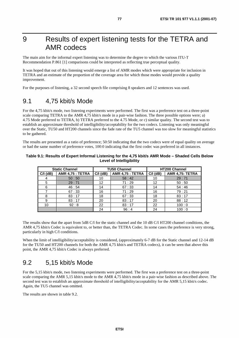
ETSI
ETSI TR 101 977 V1.1.1 (2001-07)77
9 Results of expert listening tests for the TETRA andAMR codecs
The main aim for the informal expert listening was to determine the degree to which the various ITU-TRecommendation P.861 [1] comparisons could be interpreted as reflecting true perceptual quality.
It was hoped that out of this listening would emerge a list of AMR modes which were appropriate for inclusion inTETRA and an estimate of the proportion of the coverage area for which those modes would provide a qualityimprovement.
For the purposes of listening, a 32 second speech file comprising 8 speakers and 12 sentences was used.
9.1 4,75 kbit/s ModeFor the 4,75 kbit/s mode, two listening experiments were performed. The first was a preference test on a three-pointscale comparing TETRA to the AMR 4,75 kbit/s mode in a pair-wise fashion. The three possible options were; a)4.75 Mode preferred to TETRA, b) TETRA preferred to the 4.75 Mode, or c) similar quality. The second test was toestablish an approximate threshold of intelligibility/acceptability for the two codecs. Listening was only meaningfulover the Static, TU50 and HT200 channels since the fade rate of the TU5 channel was too slow for meaningful statisticsto be gathered.
The results are presented as a ratio of preference; 50:50 indicating that the two codecs were of equal quality on averageor had the same number of preference votes, 100:0 indicating that the first codec was preferred in all instances.
Table 9.1: Results of Expert Informal Listening for the 4,75 kbit/s AMR Mode – Shaded Cells BelowLevel of Intelligibility
Static Channel TU50 Channel HT200 ChannelC/I (dB) AMR 4,75 : TETRA C/I (dB) AMR 4,75 : TETRA C/I (dB) AMR 4,75: TETRA
4 50 : 50 10 58 : 42 10 29 : 715 29 : 71 12 71 : 29 12 50 : 506 46 : 54 14 67 : 33 14 54 : 467 67 : 33 16 71 : 29 16 79 : 218 83 : 17 18 67 : 33 18 83 : 179 83 : 17 20 83 : 17 20 88 : 12
10 92 : 8 22 83 : 17 22 100 : 024 96 : 4 24 100 : 0
The results show that the apart from 5dB C/I for the static channel and the 10 dB C/I HT200 channel conditions, theAMR 4,75 kbit/s Codec is equivalent to, or better than, the TETRA Codec. In some cases the preference is very strong,particularly in high C/I conditions.
When the limit of intelligibility/acceptability is considered, (approximately 6-7 dB for the Static channel and 12-14 dBfor the TU50 and HT200 channels for both the AMR 4,75 kbit/s and TETRA codecs), it can be seen that above thispoint, the AMR 4,75 kbit/s Codec is always preferred.
9.2 5,15 kbit/s ModeFor the 5,15 kbit/s mode, two listening experiments were performed. The first was a preference test on a three-pointscale comparing the AMR 5,15 kbit/s mode to the AMR 4,75 kbit/s mode in a pair-wise fashion as described above. Thesecond test was to establish an approximate threshold of intelligibility/acceptability for the AMR 5,15 kbit/s codec.Again, the TU5 channel was omitted.
The results are shown in table 9.2.
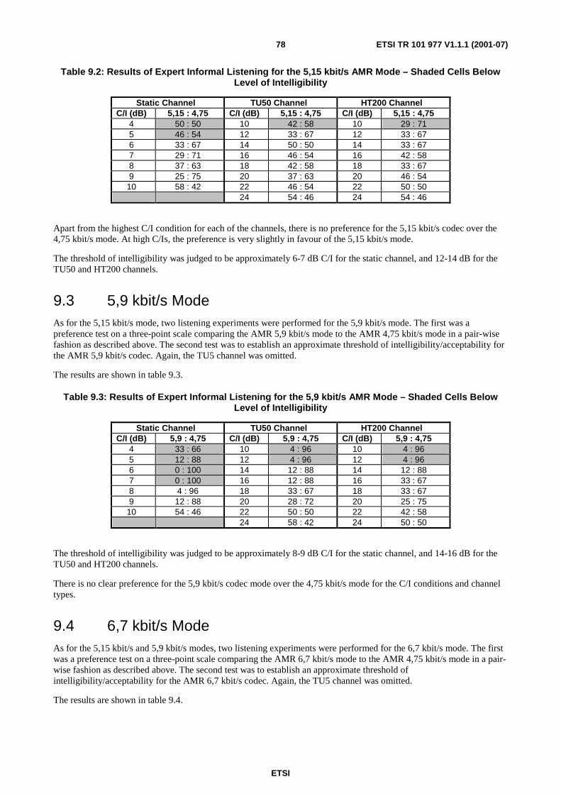
ETSI
ETSI TR 101 977 V1.1.1 (2001-07)78
Table 9.2: Results of Expert Informal Listening for the 5,15 kbit/s AMR Mode – Shaded Cells BelowLevel of Intelligibility
Static Channel TU50 Channel HT200 ChannelC/I (dB) 5,15 : 4,75 C/I (dB) 5,15 : 4,75 C/I (dB) 5,15 : 4,75
4 50 : 50 10 42 : 58 10 29 : 715 46 : 54 12 33 : 67 12 33 : 676 33 : 67 14 50 : 50 14 33 : 677 29 : 71 16 46 : 54 16 42 : 588 37 : 63 18 42 : 58 18 33 : 679 25 : 75 20 37 : 63 20 46 : 54
10 58 : 42 22 46 : 54 22 50 : 5024 54 : 46 24 54 : 46
Apart from the highest C/I condition for each of the channels, there is no preference for the 5,15 kbit/s codec over the4,75 kbit/s mode. At high C/Is, the preference is very slightly in favour of the 5,15 kbit/s mode.
The threshold of intelligibility was judged to be approximately 6-7 dB C/I for the static channel, and 12-14 dB for theTU50 and HT200 channels.
9.3 5,9 kbit/s ModeAs for the 5,15 kbit/s mode, two listening experiments were performed for the 5,9 kbit/s mode. The first was apreference test on a three-point scale comparing the AMR 5,9 kbit/s mode to the AMR 4,75 kbit/s mode in a pair-wisefashion as described above. The second test was to establish an approximate threshold of intelligibility/acceptability forthe AMR 5,9 kbit/s codec. Again, the TU5 channel was omitted.
The results are shown in table 9.3.
Table 9.3: Results of Expert Informal Listening for the 5,9 kbit/s AMR Mode – Shaded Cells BelowLevel of Intelligibility
Static Channel TU50 Channel HT200 ChannelC/I (dB) 5,9 : 4,75 C/I (dB) 5,9 : 4,75 C/I (dB) 5,9 : 4,75
4 33 : 66 10 4 : 96 10 4 : 965 12 : 88 12 4 : 96 12 4 : 966 0 : 100 14 12 : 88 14 12 : 887 0 : 100 16 12 : 88 16 33 : 678 4 : 96 18 33 : 67 18 33 : 679 12 : 88 20 28 : 72 20 25 : 75
10 54 : 46 22 50 : 50 22 42 : 5824 58 : 42 24 50 : 50
The threshold of intelligibility was judged to be approximately 8-9 dB C/I for the static channel, and 14-16 dB for theTU50 and HT200 channels.
There is no clear preference for the 5,9 kbit/s codec mode over the 4,75 kbit/s mode for the C/I conditions and channeltypes.
9.4 6,7 kbit/s ModeAs for the 5,15 kbit/s and 5,9 kbit/s modes, two listening experiments were performed for the 6,7 kbit/s mode. The firstwas a preference test on a three-point scale comparing the AMR 6,7 kbit/s mode to the AMR 4,75 kbit/s mode in a pair-wise fashion as described above. The second test was to establish an approximate threshold ofintelligibility/acceptability for the AMR 6,7 kbit/s codec. Again, the TU5 channel was omitted.
The results are shown in table 9.4.

ETSI
ETSI TR 101 977 V1.1.1 (2001-07)79
Table 9.4: Results of Expert Informal Listening for the 6,7 kbit/s AMR Mode – Shaded Cells BelowLevel of Intelligibility
Static Channel TU50 Channel HT200 ChannelC/I (dB) 6,7 : 4,75 C/I (dB) 6,7 : 4,75 C/I (dB) 6,7 : 4,75
4 33 : 66 10 4 : 96 10 0 : 1005 29 : 71 12 0 : 100 12 0 : 1006 0 : 100 14 0 : 100 14 0 : 1007 0 : 100 16 0 : 100 16 0 : 1008 0 : 100 18 0 : 100 18 0 : 1009 0 : 100 20 0 : 100 20 0 : 100
10 0 : 100 22 21 : 79 22 8 : 9224 46 : 54 24 21 : 79
The threshold of intelligibility was judged to be approximately 9-10 dB C/I for the static channel, and 16-18 dB for theTU50 and HT200 channels.
Over the full range of channel conditions, the 4,75 kbit/s mode was preferred over the 6,7 kbit/s mode.
10 ConclusionsFEC schemes were designed and evaluated for four GSM/3GPP AMR codec modes (4.75, 5.15, 5.9 and 6,7 kbit/s) aspart of the TETRA system. Both objective (ITU-T Recommendation P.861 [1]) and subjective (expert listener)evaluation of the various codec modes was performed.
The 4,75 kbit/s AMR mode was shown to provide a clear benefit, in terms of quality over most of the coverage area,when compared to the TETRA codec. The other modes of the AMR codec did not demonstrate a clear improvement inquality over the 4,75 kbit/s mode for the C/Is tested.
ETSI
ETSI TR 101 977 V1.1.1 (2001-07)80
Annex A:Software DescriptionSeveral software deliverables were produced as part of the project and these are described in this Annex; the soft-bitdemodulation error files for each of the channels, generic versions of the TETRA ccoder and cdecoder routines, a utilityto apply soft-bit errors to the output of ccoder and the processing script files.
A.1 Soft-Bit Error FilesThese files are stored under the parent directory 'Channel_Data' in subdirectories 'Static', 'TU5', 'TU50' and 'HT200'.Static channel files have the form; sc_X_soft.bin or sc_XX_soft.bin where X or XX is the C/I used to generate the file.A similar convention is used for TU5 channel files; tu5_XX_soft.bin, TU50 channel files; tu50_XX_soft.bin andHT200 channel files; ht200_XX_soft.bin.
The files comprise 1000080 short words in big-endian (HP-UX) format representing 2315 TDMA bursts of 432 bits.The short words contain values between –127 (perfect demodulation i.e. no error) to +127 (complete corruption).
A.2 Generic 'ccoder' and 'cdecoder' RoutinesThese program files are stored under the parent directory 'New_FEC'. They are based very closely on the TETRA'ccoder' and 'cdecoder' utilities that are provided as part of ETS 300 395-2 [2].
The 'ccoder' code has been made slightly more general and now accepts data in both the conventional TETRA codecformat and the format generated by the 3GPP/GSM AMR Codecs. An additional option is provided to allow one of thefour AMR modes to be selected. The command line is now of the form; ccoder infile outfile [CoderType], where theCoderType is an optional integer input which defaults to the TETRA format when not present. The value of CoderTypehas the following effect; 0=TETRA, 1=AMR_475, 2=AMR_515, 3=AMR_590 and 4=AMR_670 respectively. Theinfile must be in the form expected according to CoderType; either TETRA format or AMR format.
The 'cdecoder' has been written in a similar manner; cdecoder infile outfile [CoderType], and expects the same value ofCoderType to be used as for the encoding to ensure compatible decoding is performed. This is due to the fact that thetype of speech coder is not identifiable from the TETRA TDMA bit stream.
NOTE: After cdecoding, the AMR synthesis must be performed with the –rxframetype option in order for the badframe indication to be effective.
Two *.tab files (arrays_XX.tab and const_XX.tab) define the allocation of bits for each of the AMR modes and forTETRA at compile-time where XX is the speech codec to which the data refers. Not only is the data provided for theselected FEC modes, but also for the other FEC options tried during the creation of this report. Short command scriptfiles are provided to configure the code according to the options described in the document (create_option1,create_option2, create_option3 and create_option4) and one file configures the code according to the selected options;create_chosen_option.
A.3 Soft-Bit Error Injection RoutineThese program files are stored under the parent directory 'Chan_Err_Inject'. A single program is required to read theTETRA TDMA format files and the soft-bit channel files and to currupt the TDMA burst data according to the soft bitfiles.
The routine is executed by using the following command; inject in_file channel_file out_file, where the files are in theexpected formats. This command is independent of the speech codec being used.

ETSI
ETSI TR 101 977 V1.1.1 (2001-07)81
A.4 Script FilesThese 'C' shell files are stored under the parent directory 'Scripts'. Two sets of scripts are provided. The first set of theform 'Complete_XX_Test' was used in order to generate the ITU-T Recommendation P.861 [1] results for the curves inthis report; where XX is the speech codec to be used. The results are placed in the child directory 'Test_Results'.
The second set of command files is of the form; 'Complete_XX_Process' was used to derive the speech material for theexpert listening where again the XX is the speech codec to be used.
Two additional command files; 'Do_Every_Test' and 'Create_Listening_Data' may be used to perform all of the tests atone execution.
NOTE: These script files will not execute directly due to the absence of the source speech file (in directory'Speech_Data') and the utility to perform the ITU-T Recommendation P.861 [1] metric calculations (indirectory 'p861').

ETSI
ETSI TR 101 977 V1.1.1 (2001-07)82
History
Document history
V1.1.1 July 2001 Publication


