ETSI TR 102 069 V1.1.1 (2002-07) Technical Report Electromagnetic compatibility and Radio spectrum Matters (ERM); Technical Report on the operation of DSSS transponders in the band 865 MHz to 868 MHz, with polling frequency external to the band
Transcript
ETSI TR 102 069 V1.1.1 (2002-07)
Technical Report
Electromagnetic compatibilityand Radio spectrum Matters (ERM);
Technical Report on the operation of DSSS transpondersin the band 865 MHz to 868 MHz,
with polling frequency external to the band
ETSI
ETSI TR 102 069 V1.1.1 (2002-07) 2
Reference DTR/ERM-RM-012
Keywords radio, short range, system
ETSI
650 Route des Lucioles F-06921 Sophia Antipolis Cedex - FRANCE
Tel.: +33 4 92 94 42 00 Fax: +33 4 93 65 47 16
Siret N° 348 623 562 00017 - NAF 742 C
Association à but non lucratif enregistrée à la Sous-Préfecture de Grasse (06) N° 7803/88
Important notice
Individual copies of the present document can be downloaded from: http://www.etsi.org
The present document may be made available in more than one electronic version or in print. In any case of existing or perceived difference in contents between such versions, the reference version is the Portable Document Format (PDF).
In case of dispute, the reference shall be the printing on ETSI printers of the PDF version kept on a specific network drive within ETSI Secretariat.
Users of the present document should be aware that the document may be subject to revision or change of status. Information on the current status of this and other ETSI documents is available at
http://portal.etsi.org/tb/status/status.asp
If you find errors in the present document, send your comment to: [email protected]
Copyright Notification
No part may be reproduced except as authorized by written permission. The copyright and the foregoing restriction extend to reproduction in all media.
DECTTM, PLUGTESTSTM and UMTSTM are Trade Marks of ETSI registered for the benefit of its Members. TIPHONTM and the TIPHON logo are Trade Marks currently being registered by ETSI for the benefit of its Members. 3GPPTM is a Trade Mark of ETSI registered for the benefit of its Members and of the 3GPP Organizational Partners.
Intellectual Property Rights ................................................................................................................................4
5 Detailed information on the various aspects ............................................................................................7 5.1 Estimated number of DSSS transponders (worst condition) ..............................................................................7 5.2 Estimated number of active transponders (worst condition) ..............................................................................7 5.3 Limitation of the duty cycle of the transponders ................................................................................................8 5.4 Advantage of the use of DSSS and DTOA.........................................................................................................8 5.5 The economic benefits........................................................................................................................................8 5.6 Social benefit......................................................................................................................................................8 5.7 Spectrum requirement and justification..............................................................................................................8 5.8 Polling transmitters.............................................................................................................................................9 5.9 Technical Issues .................................................................................................................................................9 5.10 Current Regulation - Region 1 and CEPT allocation .......................................................................................10
6 Main conclusions....................................................................................................................................11 6.1 Requested ECC actions ....................................................................................................................................11
B.3 Frequency Mask .....................................................................................................................................14
C.1 Coexistence tests and studies .................................................................................................................16 C.1.1 Compatibility with CT2 (preliminary study) ....................................................................................................16 C.1.2 Compatibility with Wireless Audio and RFID (preliminary study) .................................................................16
History ..............................................................................................................................................................24
ETSI
ETSI TR 102 069 V1.1.1 (2002-07) 4
Intellectual Property Rights IPRs essential or potentially essential to the present document may have been declared to ETSI. The information pertaining to these essential IPRs, if any, is publicly available for ETSI members and non-members, and can be found in ETSI SR 000 314: "Intellectual Property Rights (IPRs); Essential, or potentially Essential, IPRs notified to ETSI in respect of ETSI standards", which is available from the ETSI Secretariat. Latest updates are available on the ETSI Web server (http://webapp.etsi.org/IPR/home.asp).
Pursuant to the ETSI IPR Policy, no investigation, including IPR searches, has been carried out by ETSI. No guarantee can be given as to the existence of other IPRs not referenced in ETSI SR 000 314 (or the updates on the ETSI Web server) which are, or may be, or may become, essential to the present document.
Foreword This Technical Report (TR) has been produced by ETSI Technical Committee Electromagnetic compatibility and Radio spectrum Matters (ERM).
1 Scope The present document applies to Radio equipment to be operated in the 865 MHz to 868 MHz frequency range and using a Direct Sequence Spread Spectrum modulation technique for asset tracking of lost or stolen items and emergency tracing of persons.
The transponders are silent and activated only in the extreme and rare condition of theft attempt and even then its transmissions are characterized by an extremely low duty cycle and short transmission bursts. The emergency tracing of persons is initiated upon request. In case of polling or interrogation of the transponder the duty cycle of the DSSS transponders is automatically limited.
Several remote base stations receive the spread spectrum transmission from the transponder. The base stations perform very accurate measurement of the time of arrival of the signal and send this information to the Control Centre. The Centre's computer calculates the location of the device using Differential Time of Arrival (DTOA) algorithms, and provides this location information to the operator or another user.
The following information is given in the annexes:
• Annex A: Detailed market information;
• Annex B: Technical information;
• Annex C: Expected compatibility issues.
2 References For the purposes of this Technical Report (TR) the following references apply:
[1] ERC/REC 70-03: "Relating to the use of Short Range Devices (SRD)".
[2] ETSI EN 300 422: "ElectroMagnetic Compatibility and Radio Spectrum Matters (ERM); Technical characteristics and test methods for wireless microphones in the 25 MHz to 3 GHz frequency range".
[3] ETSI EN 301 357: "ElectroMagnetic Compatibility and Radio Spectrum Matters (ERM); Technical characteristics and test methods for analogue cordless wideband audio devices using integral antennas operating in the CEPT recommended 863 MHz to 865 MHz frequency range".
[4] ETSI EN 300 220: "Electromagnetic compatibility and Radio spectrum Matters (ERM); Short Range Devices (SRD); Radio equipment to be used in the 25 MHz to 1 000 MHz frequency range with power levels ranging up to 500 mW".
[5] ETSI EN 303 035: "Terrestrial Trunked Radio (TETRA); Harmonized EN for TETRA equipment covering essential requirements under article 3.2 of the R&TTE Directive; Part 1: Voice plus Data (V+D)".
[6] ERC/DEC(01)02: "ERC Decision of 12 March 2001 on harmonised frequencies, technical characteristics and exemption from individual licensing of Non-specific Short".
[7] ERC/DEC(97)06: "ERC Decision of 30 June 1997 on the harmonised frequency band to be designated for Social Alarm Systems".
[8] ERC/DEC(01)04: "ERC Decision of 12 March 2001 on harmonised frequencies, technical characteristics and exemption from individual licensing of Non-specific Short Range Devices operating in the frequency bands 868.0 - 868.6 MHz, 868.7 - 869.2 MHz, 869.4 - 869.65 MHz, 869.7 - 870.0 MHz".
[9] ERC/DEC(01)18: "ERC Decision of 12 March 2001 on harmonised frequencies, technical characteristics and exemption from individual licensing of Short Range Devices used for Wireless Audio Applications operating in the frequency band 863 - 865 MHz".
ETSI
ETSI TR 102 069 V1.1.1 (2002-07) 6
[10] ERC/DEC(96)04: "ERC Decision of 7 March 1996 on the frequency bands for the introduction of the Trans European Trunked Radio System (TETRA)".
[11] ERC/REC T/R 25-08: "Coordination of frequencies in the Land Mobile Service in the range 29.7 et 960 MHz".
3 Definitions and abbreviations
3.1 Definitions For the purposes of the present document, the following terms and definitions apply:
power density: level of power in Watts per Hertz generated within the power envelope
spread spectrum modulation: modulation technique in which the energy of a transmitted signal is spread throughout a relatively large portion of the frequency spectrum
transponder: receiver-transmitter that will generate a predetermined message as a result of a proper interrogation or an inappropriate handling of the asset
polling: interrogation by the control centre to invite an asset to transmit a predetermined message
3.2 Abbreviations For the purposes of the present document, the following abbreviations apply:
CEPT European Conference of Postal and Telecommunications Administrations DSSS Direct Sequence Spread Spectrum DTOA Differential Time Of Arrival ECC Electronic Communications Committee RF Radio Frequency TLSI Tracing Lost and Stolen Items
4 Executive summary The present document reflects the general characteristics of systems for tracking lost or stolen items and emergency tracing of persons using DSSS and DTOA. It was drafted in order to assess the sharing possibilities of DSSS with existing systems operating in accordance with the CEPT regulations.
The system is designed to operate over the entire 865 MHz to 868 MHz band with polling systems external to the band.
The DSSS transponders in the band 865 MHz to 868 MHz are silent and activated only in the extreme and rare condition of theft attempt.
When activated the transmissions are characterized by:
- a low power density (see frequency mask in clause B.3),
- an extremely low duty cycle automatically limited at 0,03 % over one hour,
- short transmission bursts below 30 ms,
- and in the worst condition only 1 active transmitter in average in an area of 100 km2.
There is no automatic polling or interrogation of the transponder which could result in the duty cycle above 0,03 % during one-hour period. The duty cycle is limited by proper programming of the transponder and even in case of polling can not exceed 0,03 %.
The maximum number of DSSS transponders is estimated to be 100 units/km2, but only 0,01 unit/km2 is active.
ETSI
ETSI TR 102 069 V1.1.1 (2002-07) 7
Receiver Base stations are located as follows: in rural areas average one station in 250 km2 and urban areas average one station in 100 km2.
In average 1/3 of the receiver base stations will also have a polling transmitter.
Polling can be done by any paging transmitter (VHF or UHF) in accordance with national or CEPT regulations
These characteristics assure an efficient use of the spectrum without causing interference to other systems and allow operation of several DSSS systems in the band.
The use of DSSS and DTOA assure:
- a jamming-free operation,
- operation as well in as outdoors,
- and allows operation of other DSSS systems and SRDs in the band.
Some preliminary compatibility test and studies have been conducted and prove the possibility to operate this application in the band 865 MHz to 868 MHz. However SE 24 studies are ongoing and will define the authorized levels and characteristics.
5 Detailed information on the various aspects
5.1 Estimated number of DSSS transponders (worst condition) Let's assume a city with the population of 5 million people and about 2 million cars. An optimistic penetration rate after a few years of operation into the vehicle market will be assumed as 5 % (In Israel, for example, with about 2 Million cars, after 5 years of operation of the TLSI system there are 140 000 cars equipped with a DSSS transponder, representing a penetration of about 7 %. It should be mentioned that the atmosphere for the installation of such equipment in Israel is extremely helpful, due to the encouragement, marketing and subsidy of the insurance companies). In addition to the vehicle transponders we will assume the same number of non-vehicle transponders. This brings the total number of transponders in the specific city area to 200 000. The relevant area will be assumed as having a size of 2 000 km2, which represent a circle with the radius of about 25 km. The number of receiving base stations covering the area will be around 20 in addition to six to seven Paging Transmitters. We assume that the transponders are randomly spread over this area, which brings us to an average of 100 location units per square kilometre.
5.2 Estimated number of active transponders (worst condition) In the TLSI system the transmissions from the transponders are caused by an event which is defined as an attempt to steal the asset equipped with this device. In the vehicle market, statistically 3 % stolen vehicles out of the overall fleet per year is considered high. We will use this figure as a parameter for our further evaluation.
Since there is no organized statistical data regarding non-vehicle stolen assets, and there is no known to us comparable TLSI system used for such application at mass scale, we will assume the same 3 % "theft rate" per year for this market as well.
Based on the above estimations we calculate 6 000 theft "events" a year out of 200 000 customer base in a defined area. Randomly spread over the year, this results in around 17 events each day.
Each "event" starts with a single 26 ms transmission of a spread spectrum signal, followed by infrequent interrogations of the relevant location unit for further monitoring of its movements, until the completion of the recovery mission. Based on the experience gained by several years of successful operation of vehicle recovery service, we assume maximum of 100 interrogations per event. The time delays between consecutive interrogations can range from few s to several hours. Assuming that all 100 interrogations are performed during the same day, we calculate the total number of interrogations per day to be 1 700, meaning that during the day 1,700 transmissions of 26 ms each, are performed in the area of 25 km radius. This equals to a total of 44,2 s of transmission per day. Assuming that the majority of theft attempts are performed during a 12 hour period, this results an average of one 26 ms-long transmission every 25 s, occurring at random location throughout 2 000 km2 area. In average, the geographical density of active stolen assets with location device each day will be less than one per 100 km2.
ETSI
ETSI TR 102 069 V1.1.1 (2002-07) 8
5.3 Limitation of the duty cycle of the transponders The clause above demonstrates the low number of active transponders in given area. In order however to assure interference free operation of the transponders an automatically limitation of the duty cycle to the maximum level of 0,03 % over a one hour period will be built in.
It remains a potential future problem, that if the traffic pattern for the system far exceeds that anticipated for the initially believed anti theft duty, there may be an interference issue.
5.4 Advantage of the use of DSSS and DTOA Current solutions for the location of stolen items might not be able to resist to the slightest attempt of radio jamming. Once these solutions will be widely installed, such low-cost and simple "electronic warfare" will be practised by thieves and will no doubt cause "collapse" of these protective measures.
DTOA location technology utilizing the DSSS communication technique is optimally suited to address the above problem and to present a reliable generic solution for the tracking of stolen assets.
This technology not only possesses anti-jamming capability, but also enables location in dense urban areas and inside buildings.
5.5 The economic benefits The trade in stolen items has become an international problem and a growing number of these items are taken from one country to another. With the opening of borders within Europe there is an increasing need for tracking and tracing of lost and stolen items. Many stolen items such as cars are actually sold in other European countries. The losses associated with car theft are estimated to be hundreds of millions of Euro each year. Losses associated with theft of other items are also extremely high. Currently these systems are deployed in several major cities in South America and in the USA. In Israel this system is operated with nation-wide coverage. During few years of operation in Israel only, the operator of the DSSS location system has saved insurance companies over 100 million US dollar. We estimate that introduction of this technology in Europe will bring significantly higher economical benefits.
5.6 Social benefit In addition to the economic benefit, introduction of this technology will contribute to the quality of life of specific categories of population (emergency tracing). This technology is also designed for tracking applied for high-risk personnel (police, security personnel, etc.), emergency assistance and disabled people location (e.g. Alzheimer disease patients). The emergency tracing of persons is initiated upon request.
5.7 Spectrum requirement and justification The Strategic Plan for the 862 MHz to 868 MHz proposed by the SRD MG and approved by FM WG offers the opportunity for introduction of DSSS technologies.
"The frequency band 863 MHz to 870 MHz should be considered for non-specific spread spectrum SRD applications by using Direct Sequence Spread Spectrum (DSSS) and/or Frequency Hopping Spread Spectrum (FHSS) with a power level of 25 mW. The technical param for the power density for DSSS and the channel scheme/power level/hopping system should be defined based on detailed compatibility studies in order to provide sufficient protection to other services in the band and in particular safety services such as Social Alarms."
This DSSS system is able to operate in the band 865 MHz to 868 MHz without causing potential interference to other systems operating in the same band due to its RF characteristics and specific operational concept based on infrequent emergency transmissions from devices randomly spread over a large geographical area.
The characteristics of the transponders assure this interference -free operation and allow the operation of other DSSS and SSRD systems in the band.
ETSI
ETSI TR 102 069 V1.1.1 (2002-07) 9
5.8 Polling transmitters Polling transmitters are operating outside the band 862 MHz to 870 MHz and are using existing paging channels in accordance with existing rules and procedures. The frequency band used depends on the region of operation.
There is no uncontrolled automatic polling and the transponders are programmed to ensure that response from the transponders is automatically stopped if the allowed duty cycle over one hour is reached.
Concerning the polling of the tracking units, it should be noted that there is no "CEPT wide" recommendation on such paging systems, especially since ERMES failed. It is wondered how this polling can be done in case of cross border situations with "existing paging systems".
5.9 Technical Issues Applications and Market information: see annex A.
Technical description: see annex B.
Expected Compatibility studies: see annex C.
ETSI
ETSI TR 102 069 V1.1.1 (2002-07) 10
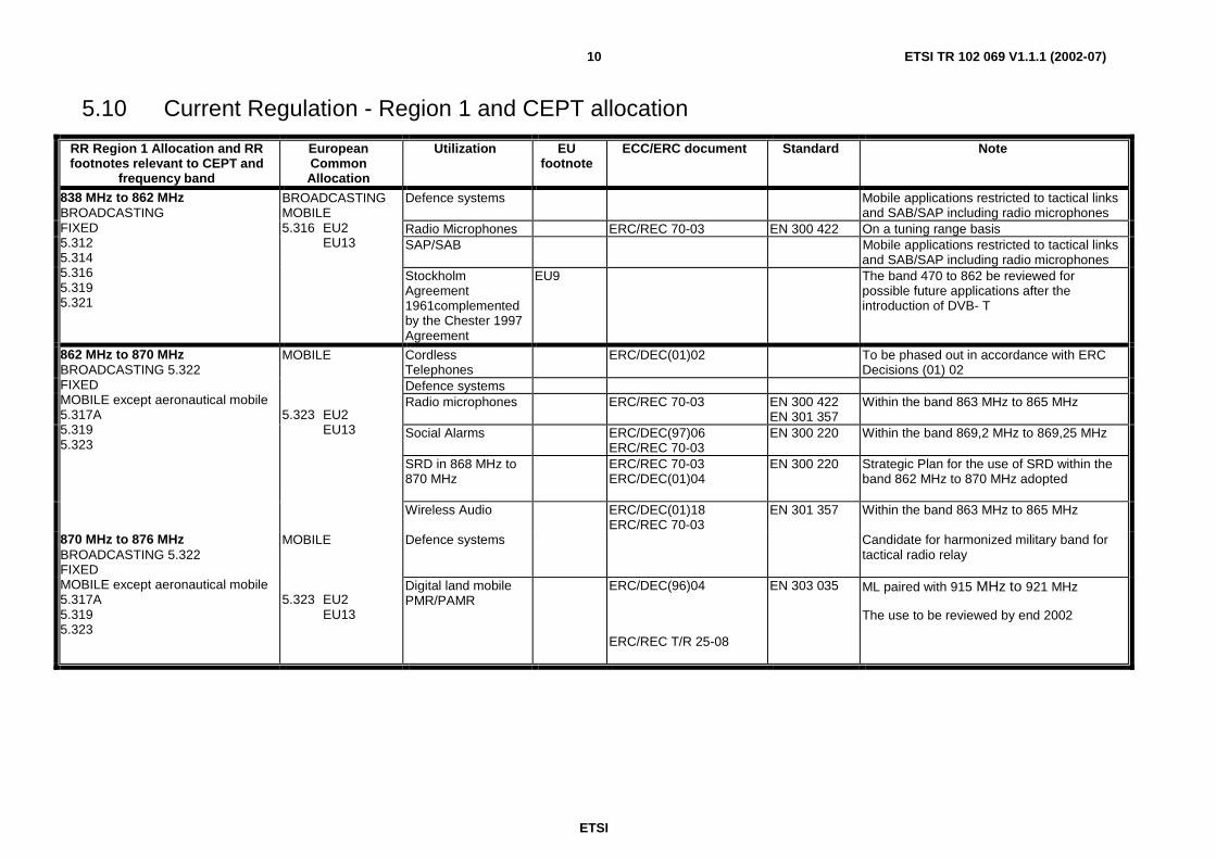
5.10 Current Regulation - Region 1 and CEPT allocation
RR Region 1 Allocation and RR footnotes relevant to CEPT and
frequency band
European Common Allocation
Utilization EU footnote
ECC/ERC document Standard Note
Defence systems
Mobile applications restricted to tactical links and SAB/SAP including radio microphones
Radio Microphones ERC/REC 70-03 EN 300 422 On a tuning range basis SAP/SAB Mobile applications restricted to tactical links
Stockholm Agreement 1961complemented by the Chester 1997 Agreement
EU9 The band 470 to 862 be reviewed for possible future applications after the introduction of DVB- T
Cordless Telephones
ERC/DEC(01)02 To be phased out in accordance with ERC Decisions (01) 02
Defence systems Radio microphones ERC/REC 70-03 EN 300 422
EN 301 357 Within the band 863 MHz to 865 MHz
Social Alarms ERC/DEC(97)06 ERC/REC 70-03
EN 300 220 Within the band 869,2 MHz to 869,25 MHz
SRD in 868 MHz to 870 MHz
ERC/REC 70-03 ERC/DEC(01)04
EN 300 220 Strategic Plan for the use of SRD within the band 862 MHz to 870 MHz adopted
862 MHz to 870 MHz BROADCASTING 5.322 FIXED MOBILE except aeronautical mobile 5.317A 5.319 5.323
MOBILE 5.323 EU2 EU13
Wireless Audio ERC/DEC(01)18 ERC/REC 70-03
EN 301 357 Within the band 863 MHz to 865 MHz
Defence systems Candidate for harmonized military band for tactical radio relay
870 MHz to 876 MHz BROADCASTING 5.322 FIXED MOBILE except aeronautical mobile 5.317A 5.319 5.323
MOBILE 5.323 EU2 EU13
Digital land mobile PMR/PAMR
ERC/DEC(96)04
ERC/REC T/R 25-08
EN 303 035 ML paired with 915 MHz to 921 MHz
The use to be reviewed by end 2002
ETSI
ETSI TR 102 069 V1.1.1 (2002-07) 11
6 Main conclusions The UHF band 865 MHz to 868 MHz meets the market requirements in allowing different DSSS systems to operate providing co-existence with other SRD applications.
The low power density due to DSSS modulation scheme, very low duty cycle and the short transmission pulse duration, assures the efficient use of the spectrum. Preliminary compatibility studies have been conducted involving DSSS systems, CT2, Analogue Wireless Audio systems and RFID systems.
6.1 Requested ECC actions Compatibility evaluations and studies for services as defined in annex C.
Update of ERC/REC 70-03 [1].
ETSI
ETSI TR 102 069 V1.1.1 (2002-07) 12
Annex A: Detailed market information
A.1 Range of applications for TLSI using DSSS Differential Time of Arrival (DTOA) location technology utilizing Direct Sequence Spread Spectrum communication techniques is optimally suited to present a reliable generic solution for the location of "stolen items" as well as other related applications. Several operators of security related applications are successfully using this technology.
The main and traditional application in this field is tracing of stolen cars. Recently this technology is being applied to the additional applications and specifically tracing of wide range of stolen items, like computers, expensive electronics equipment, packages, valuables.
Another application of this technology, which is highly appreciated, is emergency tracing of persons applied for high-risk personnel (police, security personnel etc.), emergency assistance and disabled people location (e.g. Alzheimer disease patients).
A.2 Market information for asset tracking using DSSS Asset tracking systems utilizing DSSS communication technique are usually associated with multilateral terrestrial systems based on DTOA technology. Due to inherent DSSS requirement for relatively wideband spectrum allocation, introduction of this technology was limited to the regions where this allocation was possible. These regions include the United States, South and Central America, Australia and Israel. In the US and other American markets the systems utilize several bands in 902 - 928 MHz (ISM) range.
A number of operators are providing services in the above regions for various security - oriented applications (stolen vehicle and item recovery, personal security, emergency assistance). Due to the relative "short range" nature of these systems its deployment is most effective in urban areas. Currently these systems are deployed in several major US cities (Los Angeles, Detroit, Miami, Houston, Dallas, Chicago, and Orlando), in Sao Paulo, Brazil, in Buenos Aires, Argentina, in the state of Israel (nation-wide coverage) and additional markets. Total number of vehicles, equipped with the related location device, is estimated over 300 000. During few years of operation in Israel only, the operator of the DSSS location system has saved insurance companies over 100 million US dollar.
With recently introduced cargo and personal location devices the potential market of the technology is increased dramatically.
Security and Safety segment of Location Based Services, associated with equipment sale only, is estimated at the level of 500 million US dollar in 2001, increasing to 1 billion US dollar in 2002 and to 4 billion US dollar in 2005. Based on its unique features, Spread Spectrum technology is expected to become a major player in this market.
ETSI
ETSI TR 102 069 V1.1.1 (2002-07) 13
Annex B: Technical information
B.1 Technical description The principles of operation of the system are as follows:
The transmission of the spread spectrum signal from the transponder (uplink) is triggered either by predefined event transferred to the device via physical connection (e.g. unauthorized opening of the door or box, activation of vibration of impact sensors, etc.) or remotely by an interrogation signal (narrow-band paging) sent by a distant operator and addressed to the specific device (downlink).
Several remote base stations receive the spread spectrum transmission from the transponder. The base stations perform very accurate measurement of the time of arrival of the signal and send this information to the Control Centre. The Centre's computer calculates the location of the device using Differential Time of Arrival (DTOA) algorithms, and provides this location information to the operator or another user. Single uplink transmission is adequate to perform reliable location of the device.
Downlink from the base station utilizes standard paging channel and is not part of this discussion.
B.2 Block Diagram
The Uplink DSSS transmission is initiated by the transponder either from predefined event or by request
- The Uplink signal (3) is received by several Base Stations where accurate TOA is measured and transferred to the Control Centre (4).
- The Control Centre initiates the interrogation by Downlink (1 and 2).
- The Downlink transmission to interrogate the transponder is a standard paging signal from the base station and utilizes a separate frequency band.
ETSI
ETSI TR 102 069 V1.1.1 (2002-07) 14
- The Control Centre's computer utilizes DTOA (Differential TOA) algorithms for accurate location determination and provides this information to the operator (5).
B.4 Duty Cycle The number of active transponders is in the worst condition estimated to be less then one per 100 km2.
There is no automatic polling or interrogation of the transponder, which could result in the duty cycle above 0,03 % during one-hour period. In order however to assure interference free operation of the transponders an automatically limitation of the duty cycle to the maximum level of 0,03 % over a one hour period will be built in.
B.5 Technical justifications for spectrum Spread Spectrum systems inherently need wide band spectrum. Use of Direct Sequence Spread Spectrum technology for location purposes provide four critical features:
a) enable very accurate time measurement of the signal reception;
b) enable transmission of very short pulses;
c) presents very low probability of interference to other devices operating in the same band;
d) provides means for successfully overcoming the multipath phenomena in urban environment.
Due to the intended use of the system in urban environment, sufficient propagation can only be achieved working in the UHF band below 1 GHz.
The band 865 MHz to 868 MHz would be suitable for DSSS on frequency sharing basis.
ETSI
ETSI TR 102 069 V1.1.1 (2002-07) 16
Annex C: Expected compatibility issues
C.1 Coexistence tests and studies In addition to the sharing tests mentioned below, compatibility studies between different services and systems operating in the same band are requested from SE 24.
Studies will be necessary between DSSS and other systems using the same band or adjacent bands:
- Tactical Radio Relay Link (TRRL) where or when applicable.
- CT2 systems and with other SRD's such as tele-alarm, telemetry, RFID, FHSS and cordless audio devices in adjacent bands and within the defined sub-bands.
- Television (channel 69) and aeronautical radionavigation in some countries (S5.323).
CEPT SE24 has been requested by WGFM to carry out a compatibility study between various systems in the 860 MHz to 872 MHz frequency band.
C.1.1 Compatibility with CT2 (preliminary study) SE24 evaluated the study of electromagnetic compatibility of CT2 cordless telephony system installations and vehicle location (system operating in the 864 MHz to 868 MHz bandwidth) performed by the Wroclaw Polytechnic Institute of Telecommunications and Acoustics. SE24 concluded (see M09_31R0_SE24_862_LS-SRDMG attachment 1):
Quote
Document M09_12 RO_SE24_862 on the compatibility between CT2 and DSSS in the 864 MHz to 868 MHz band. This report of measurements shows that 4W DSSS with 26 ms duration pulse does not provide unacceptable degradation of service (link establishment, voice communication) for the CT2.The data communications was not tested but is not expected to be perturbed on the view of the results on the voice communication. More studies may be undertaken but the general sentiment in SE24 is that the limitation to the band 862 MHz to 868 MHz of wide spectrum SRDs should solve most of the compatibility issues.
Unquote
C.1.2 Compatibility with Wireless Audio and RFID (preliminary study)
Preliminary sharing tests with other SRD systems in the band (RFID and Wireless Audio) were performed in the Philips plant in Heverlee Belgium (M10_11RO_SE24 attachment 2). The results of the test show that there is no interference from DSSS system to the RFID system and the coordination distance around the wireless audio is only few m in a free space environment. The probability to have a DSSS device in this coordination area is negligible.
In the document M10_11RO_SE24 (attachment 2) a recalculation of duty cycle and location transmitter's density for the worst case scenario was performed. Results of these calculations show that in a worst case scenario, with 200 000 devices spread over the city of 25 km radius the total duration of all transmissions is only about 7 min per day, representing 17 000 transmissions of 26 ms each, randomly spread over the whole area.
ETSI
ETSI TR 102 069 V1.1.1 (2002-07) 17
C.2 Compatibility DSSS/CT2 Subject: Compatibility Studies in the 862 MHz to 870 MHz band. Liaison Statement to SRD/MG
Status: Submission
Source: PTSE24
Date: 04. 07. 2001
Dear Soren,
PT SE24 considered 2 contributions in relation with the 862-870 MHz study:
Document M09_08 on Social Alarms
A short study will be undertaken for the next SE24 meeting.
Document M09_12 on the compatibility between CT2 and DSSS in the 864 MHz to 868 MHz band.
This report of measurements shows that 4W DSSS with 26 ms duration pulse does not provide unacceptable degradation of service (link establishment, voice communication) for the CT2.
The data communications was not tested but is not expected to be perturbed on the view of the results on the voice communication.
More studies may be undertaken but the general sentiment in SE24 is that the limitation to the band 862-868 MHz of wide spectrum SRDs should solve most of the compatibility issues.
Best regards
Yves Ollivier
Chairman SE24
ETSI
ETSI TR 102 069 V1.1.1 (2002-07) 18
C.3 Compatibility DSSS/Wireless, DSSS/RFID Subject: Band 862 MHz to 870 MHz Sharing possibilities DSSS
Status: Consideration
Source: SAIT-TADIRAN
Date: 04. 12. 2001
Attached the report of the compatibility tests involving DSSS TLSI versus Analog Wireless Audio in the band 863 MHz to 865 MHz and DSSS TLSI versus RFID in the band 865 MHz to 868 MHz.
ETSI
ETSI TR 102 069 V1.1.1 (2002-07) 19
Report on DSSS TLSI Compatibility Tests
With Wireless Audio in the 863-865 MHz band
and RFID in the band 865 -868 MHz.
1 Introduction
On 20 October 2001 compatibility tests were performed between Analogue Wireless Audio, RFID and DSSS TLSI (Direct Sequence Spread Spectrum Tracing Lost and Stolen Items) systems operating in the 863 MHz to 870 MHz. The tests were performed in the PHILIPS plant in Leuven Belgium and were attended by Mr Felix Elsen from Philips, Mr John Falck LPRA, Mr Roman Sternberg from Tadiran Telematics/IAEI, and Mr Andre Dewulf representing SAIT.
2 Equipment
2.1 DSSS TLSI
SAIT -Tadiran presented two DSSS transmitters of type "TULIP" with center frequency respectively on 866 MHz and 866,4 MHz. The equipment was programmed to transmit its 26 ms bursts every 2 s in order to make measurements with the audio equipment possible. In addition, there was a possibility to program the transmitters to transmit a continuous spread spectrum signal for several s in order to enable spectrum measurements with the spectrum analyzer. The normal transmission duration of the above DSSS unit is 26 ms maximum and duty cycle of the DSSS TLSI is far below 0,1 %.
2.2 RFID
The LPRA were able to obtain the loan of a prototype reader from BiStar with firmware that had been modified for the tests. Certain param of the reader could be set externally from a PC using a special software program. The software permitted adjustment of the power level, the frequency of transmission, the rise time of the carrier envelope and the duty cycle. It was not possible to set the reader to continuous modulated carrier.
For the tests at the Philips facility it was decided to operate the reader in both the free-run and sample modes.
2.3 Wireless Audio Equipment
2.3.1 A range of Analog Wireless Audio equipment built by different manufacturers was provided. These included:
• Philips SBC HC 8450 (500 kHz).
• Philips SBC HC 8305 (500 kHz).
• Philips SBC HC 8395 (300 kHz).
• Philips Active Surround Speaker AD901WA/12.
• Sennheiser HD R 65 (300 kHz).
• Sony MDR-RF845RK (200 kHz).
2.3.2 From previous assessments all of the devices with the exception of the Sony unit were estimated to have a bandwidth of between 300 kHz and 500 kHz. The Sony unit was estimated to have a bandwidth of 200 kHz.
2.3.3 A portable CD player was supplied with a suitable CD to provide an input to the base stations of the cordless audio devices.
3 Description of the Tests
The tests were divided into three stages as defined below:
- Measurement of transmitted power and power density from the DSSS transmitters
- Compatibility with Analog Wireless Audio systems
ETSI
ETSI TR 102 069 V1.1.1 (2002-07) 20
- Compatibility with RFID equipment
The procedure adopted for each stage is described below:
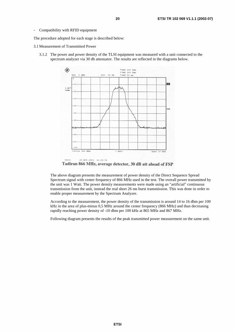
3.1 Measurement of Transmitted Power
3.1.2 The power and power density of the TLSI equipment was measured with a unit connected to the spectrum analyzer via 30 db attenuator. The results are reflected in the diagrams below.
The above diagram presents the measurement of power density of the Direct Sequence Spread Spectrum signal with center frequency of 866 MHz used in the test. The overall power transmitted by the unit was 1 Watt. The power density measurements were made using an "artificial" continuous transmission from the unit, instead the real short 26 ms burst transmission. This was done in order to enable proper measurement by the Spectrum Analyzer.
According to the measurement, the power density of the transmission is around 14 to 16 dbm per 100 kHz in the area of plus-minus 0,5 MHz around the center frequency (866 MHz) and than decreasing rapidly reaching power density of -10 dbm per 100 kHz at 865 MHz and 867 MHz.
Following diagram presents the results of the peak transmitted power measurement on the same unit.
ETSI
ETSI TR 102 069 V1.1.1 (2002-07) 21
This diagram shows that the maximum peak power as measured in 100 kHz bandwidth is about +25 dbm in the center of the spectrum mask and reaches -5 dbm at 865 MHz and 867 MHz. Larger measurement bandwidth would bring the max value close to the transmitted 1Watt power near the carrier frequency.
During the actual compatibility tests the unit was connected to the omnidirectional antenna of 0 dbi gain.
The power density and peak power measured for 866,4 MHz unit were identical to the above with according spectrum shift by 0,4 MHz.
3.2 Compatibility with Analog Wireless Audio systems
3.2.1 With the TLSI transmitting at 866 MHz the wireless audio equipment was moved in from the distance of twenty m toward the interfering transmitter. The tests were performed with the Wireless Audio base station transmitting an unmodulated carrier at a frequency of 864,75 MHz. This represented the worst case condition. Afterwards modulated (music) information was transmitted to evaluate the interference in the presence of the "real" modulated signal. The received signal at the Wireless Audio headphones or loudspeaker was monitored subjectively while being moved progressively closer to the DSSS transmitter. The distance from the TLSI transmitter was recorded at which deterioration in the quality of the audio signal was just detectable. Depending on the quality level of the wireless receiving device this range was between 4 m to 8 m. Test with music transmitted from the Wireless Audio base station revealed that the just detectable deterioration appeared only at the distance closer than three to four m depending on the receiver quality. This is because the low level introduced interference is masked by the music content.
3.2.2 With the DSSS transmitter center frequency moved to 866,4 MHz the distance recorded at which deterioration in the quality of the audio signal was just detectable was six m with unmodulated signal and three m with music.
3.2.3 Conditions on the test site:
The test was done in an office environment where the TLSI transmitter was put in a meeting room (only wood office walls, no stone or concrete) and the remainder of the test positions where made in adjacent corridors and large lab. office space.
All tests done with the devices in stereo mode and tuned to their max operating frequency (864 750 MHz).
ETSI
ETSI TR 102 069 V1.1.1 (2002-07) 22
3.3 Interference from Analog Wireless Audio to DSSS TLSI
Several base stations receive the DSSS TLSI transmitter signal simultaneously. Interference to one base station receiver will not hamper operation. In addition, relatively narrow band audio transmission will not present a noticeable interference to the TLSI spread spectrum base station receiver.
4 Compatibility of DSSS TLSI with RFID equipment.
The DSSS TLSI module was positioned at a distance of approximately 2 m from the reader directly in its "line of fire". With the DSSS transmitter switched off the maximum reading range of a tag was measured. The transmitter was switched on and the measurement repeated. It was noted that there was no difference between the two measurements.
The possibility of interference to the DSSS TLSI module from the RFID reader was discussed. Several base stations receive the DSSS TLSI transmitter signal simultaneously. Interference to one base station receiver will not hamper operation.
In addition, due to the characteristics of DSSS modulation, interference from the reader was not possible. With the equipment supplied for the tests this statement could not be verified experimentally.
5 Conclusions
Based on the results of the tests it was possible to draw the following conclusions:
5.1 DSSS TLSI versus Analog Wireless Audio
With the TLSI transmitter at 866 MHz with the power of 1 Watt and transmitting 26 ms every 2 s the coordination area is 8 m with no modulation signal and 4 m with music transmission.
With the center frequency moved to 866,4 MHz the coordination area is 6 m and 3 m without and with music respectively.
It should be noted that the tests were performed using absolutely worst and impractical conditions:
1) The repetition rate of the interfering signal during the test was one in 2 s. In practice, given worst case operational scenario the duty cycle is less than 0,1 %, meaning that the maximum repetition rate is one transmission in 30 s. But even than the repetition is for only a limited number of transmissions.
2) During the tests no obstacles between the interfering DSSS transmitter and the "victim" receiver were present (direct line of sight). In reality this situation is extremely unlikely.
3) The tests did not reflect the random nature of the TLSI transmitter's operation in real application. The practical chances of TLSI transmitter to be in such "dangerous" vicinity of the "victim" audio receiver and to "go on" while the audio system is operational are negligible (except in the cases when the owner of the audio equipment is also the thief himself…).
The results of the tests enable us to verify and modify the preliminary conclusions as presented in SE24M10 document number M10_11RO_SE24 on the subject of "Sharing Study Direct Sequence Spread Spectrum with Wireless Audio". In this document we tried to estimate the probability of finding DSSS transmitter in the "dangerous" vicinity of the "victim audio" receiver for the worst-case operational scenario of fully deployed system in dense urban environment. We based our evaluation on the assumption of the "dangerous" area to be of 100 m radius. With this assumption we calculated a probability of one to four that sometimes during the day a single pulse of 26 ms' duration will appear at the "dangerous" vicinity of the specific audio receiver. Now, with the updated 4 m radius (with music presence) this probability is reduced from one to four to one to 2 500!
Based on the above results we conclude that there is no incompatibility between Analog Wireless Audio and DSSS TLSI.
5.2 DSSS TLSI versus RFID
The results indicate that there is no interference between RFID systems and DSSS equipment.
ETSI
ETSI TR 102 069 V1.1.1 (2002-07) 23
Annex D: Bibliography
• Directive 1999/5/EC of the European Parliament and of the Council of 9 March 1999 on radio equipment and telecommunications equipment and the mutual recognition of their conformity.
• ETSI EN 300 220-1: "Electromagnetic compatibility and Radio spectrum Matters (ERM); Short Range Devices (SRD); Radio equipment to be used in the 25 MHz to 1 000 MHz frequency range with power levels ranging up to 500 mW; Part 1: Technical characteristics and test methods".
• Council Directive 98/34/EC laying down a procedure for the provision of information in the field of technical standards and regulations.
• ETSI ETR 028: "Radio Equipment and Systems (RES); Uncertainties in the measurement of mobile radio equipment characteristics".