81
ETSI TR 102 638 V1.1.1 (2009-06) Technical Report Intelligent Transport Systems (ITS); Vehicular Communications; Basic Set of Applications; Definitions
| Date post: | 07-Jul-2018 |
| Category: |
Documents |
| Upload: | truongcong |
| View: | 220 times |
| Download: | 0 times |
ETSI TR 102 638 V1.1.1 (2009-06)
Technical Report
Intelligent Transport Systems (ITS);Vehicular Communications;
Basic Set of Applications;Definitions
ETSI
ETSI TR 102 638 V1.1.1 (2009-06) 2
Reference DTR/ITS-0010001
Keywords Application, ITS
ETSI
650 Route des Lucioles F-06921 Sophia Antipolis Cedex - FRANCE
Tel.: +33 4 92 94 42 00 Fax: +33 4 93 65 47 16
Siret N° 348 623 562 00017 - NAF 742 C
Association à but non lucratif enregistrée à la Sous-Préfecture de Grasse (06) N° 7803/88
Important notice
Individual copies of the present document can be downloaded from: http://www.etsi.org
The present document may be made available in more than one electronic version or in print. In any case of existing or perceived difference in contents between such versions, the reference version is the Portable Document Format (PDF).
In case of dispute, the reference shall be the printing on ETSI printers of the PDF version kept on a specific network drive within ETSI Secretariat.
Users of the present document should be aware that the document may be subject to revision or change of status. Information on the current status of this and other ETSI documents is available at
http://portal.etsi.org/tb/status/status.asp
If you find errors in the present document, please send your comment to one of the following services: http://portal.etsi.org/chaircor/ETSI_support.asp
Copyright Notification
No part may be reproduced except as authorized by written permission. The copyright and the foregoing restriction extend to reproduction in all media.
© European Telecommunications Standards Institute 2009.
All rights reserved.
DECTTM, PLUGTESTSTM, UMTSTM, TIPHONTM, the TIPHON logo and the ETSI logo are Trade Marks of ETSI registered for the benefit of its Members.
3GPPTM is a Trade Mark of ETSI registered for the benefit of its Members and of the 3GPP Organizational Partners. LTE™ is a Trade Mark of ETSI currently being registered
for the benefit of its Members and of the 3GPP Organizational Partners. GSM® and the GSM logo are Trade Marks registered and owned by the GSM Association.
ETSI
ETSI TR 102 638 V1.1.1 (2009-06) 3
Contents
Intellectual Property Rights ................................................................................................................................ 6
Foreword ............................................................................................................................................................. 6
1 Scope ........................................................................................................................................................ 7
2 References ................................................................................................................................................ 8
2.1 Normative references ......................................................................................................................................... 8
2.2 Informative references ........................................................................................................................................ 8
3 Definitions and abbreviations ................................................................................................................... 9
3.1 Definitions .......................................................................................................................................................... 9
3.2 Abbreviations ................................................................................................................................................... 10
4 V2X application layer model ................................................................................................................. 10
5 V2X facilities layer model and facilities ................................................................................................ 12
5.1 Station positioning ............................................................................................................................................ 13
5.2 Mobile station dynamic monitoring ................................................................................................................. 13
5.3 Station state monitoring .................................................................................................................................... 14
5.4 Services management ....................................................................................................................................... 14
5.5 LDM management ............................................................................................................................................ 15
5.6 Messages management ..................................................................................................................................... 15
5.7 Security access management ............................................................................................................................ 16
5.8 Time management ............................................................................................................................................ 16
5.9 Information support .......................................................................................................................................... 16
5.10 Communication support ................................................................................................................................... 17
6 Basic Set of Applications definition ....................................................................................................... 17
6.1 Summary of BSA content ................................................................................................................................. 17
6.1.1 Cooperative road safety .............................................................................................................................. 18
6.1.2 Cooperative traffic efficiency ..................................................................................................................... 18
6.1.3 Co-operative local services and global internet services ............................................................................ 18
Annex A: BSA selection and assessment method ................................................................................ 19
A.1 BSA assessment method ........................................................................................................................ 19
A.2 Stakeholders assessment results ............................................................................................................. 20
A.3 PRE-DRIVE V2X use cases selection ................................................................................................... 22
Annex B: Users needs and requirements for the selection of the BSA .............................................. 23
B.1 Strategic requirements ............................................................................................................................ 23
B.2 Economical requirements ....................................................................................................................... 23
B.3 System Capabilities requirements .......................................................................................................... 23
B.4 System performances requirements ........................................................................................................ 25
B.5 Organizational requirements .................................................................................................................. 25
B.6 Legal requirements ................................................................................................................................. 25
B.7 Standardization and certification requirements ...................................................................................... 25
Annex C: Illustration of ITS use case catalogue .................................................................................. 26
C.1 Co-operative road safety ........................................................................................................................ 26
C.1.1 Vehicle status warnings .................................................................................................................................... 26
C.1.1.1 Emergency electronic brake lights .............................................................................................................. 26
C.1.1.2 Safety function out of normal condition warning ....................................................................................... 27
ETSI
ETSI TR 102 638 V1.1.1 (2009-06) 4
C.1.2 Vehicle type warnings ...................................................................................................................................... 28
C.1.2.1 Emergency vehicle warning ........................................................................................................................ 28
C.1.2.2 Slow vehicle warning.................................................................................................................................. 29
C.1.2.3 Motorcycle warning .................................................................................................................................... 30
C.1.2.4 Vulnerable road user Warning .................................................................................................................... 31
C.1.3 Traffic hazard warnings .................................................................................................................................... 32
C.1.3.1 Wrong way driving warning ....................................................................................................................... 32
C.1.3.2 Stationary vehicle warning ......................................................................................................................... 33
C.1.3.3 Traffic condition warning ........................................................................................................................... 34
C.1.3.4 Signal violation warning ............................................................................................................................. 35
C.1.3.5 Roadwork warning ...................................................................................................................................... 36
C.1.3.6 Decentralized floating car data ................................................................................................................... 37
C.1.4 Dynamic vehicle warnings ............................................................................................................................... 38
C.1.4.1 Overtaking vehicle warning ........................................................................................................................ 38
C.1.4.2 Lane change assistance ............................................................................................................................... 39
C.1.4.3 Pre-crash sensing warning .......................................................................................................................... 40
C.1.4.4 Co-operative glare reduction....................................................................................................................... 41
C.1.5 Collision Risk Warning .................................................................................................................................... 42
C.1.5.1 Across traffic turn collision risk warning ................................................................................................... 42
C.1.5.2 Merging Traffic Turn Collision Risk Warning ........................................................................................... 43
C.1.5.2.1 Co-operative merging assistance ........................................................................................................... 44
C.1.5.3 Hazardous location notification .................................................................................................................. 45
C.1.5.4 Intersection Collision Warning ................................................................................................................... 46
C.1.5.5 Co-operative forward collision warning ..................................................................................................... 47
C.1.5.6 Collision Risk Warning from RSU ............................................................................................................. 48
C.2 Traffic Efficiency ................................................................................................................................... 49
C.2.1 Regulatory/contextual speed limits .................................................................................................................. 49
C.2.2 Traffic light optimal speed advisory ................................................................................................................. 50
C.2.3 Traffic information and recommended itinerary .............................................................................................. 51
C.2.4 Enhanced route guidance and navigation ......................................................................................................... 52
C.2.5 Intersection management .................................................................................................................................. 53
C.2.6 Co-operative flexible lane change .................................................................................................................... 54
C.2.7 Limited access warning, detour notification ..................................................................................................... 55
C.2.8 In-vehicle signage............................................................................................................................................. 56
C.2.9 Electronic toll collect ........................................................................................................................................ 57
C.2.10 Co-operative adaptative cruise control ............................................................................................................. 58
C.2.11 Co-operative vehicle-highway automation system (Platoon) ........................................................................... 59
C.3 Others ..................................................................................................................................................... 60
C.3.1 Point of interest notification ............................................................................................................................. 60
C.3.2 Automatic access control/parking access ......................................................................................................... 61
C.3.3 Local electronic commerce............................................................................................................................... 62
C.3.4 Car rental/sharing assignment/reporting ........................................................................................................... 63
C.3.5 Media downloading .......................................................................................................................................... 64
C.3.6 Map download and update................................................................................................................................ 65
C.3.7 Ecological/economical drive ............................................................................................................................ 66
C.3.8 Instant messaging ............................................................................................................................................. 67
C.3.9 Personal data synchronization .......................................................................................................................... 68
C.3.10 SOS service ...................................................................................................................................................... 68
C.3.11 Stolen vehicle alert ........................................................................................................................................... 70
C.3.12 Remote diagnosis and just in time repair notification ...................................................................................... 71
C.3.13 Vehicle relation management ........................................................................................................................... 72
C.3.14 Vehicle data collect for product life cycle management ................................................................................... 73
C.3.15 Insurance and financial Services ...................................................................................................................... 74
C.3.16 Fleet management............................................................................................................................................. 75
C.3.17 Vehicle software/data provisioning and update ................................................................................................ 76
C.3.18 Loading zone management ............................................................................................................................... 77
C.3.19 Vehicle and RSU data calibration .................................................................................................................... 78
Annex D: Tentative optimistic deployment roadmap ......................................................................... 79
Annex E: Bibliography .......................................................................................................................... 80

ETSI
ETSI TR 102 638 V1.1.1 (2009-06) 5
History .............................................................................................................................................................. 81
ETSI
ETSI TR 102 638 V1.1.1 (2009-06) 6
Intellectual Property Rights IPRs essential or potentially essential to the present document may have been declared to ETSI. The information pertaining to these essential IPRs, if any, is publicly available for ETSI members and non-members, and can be found in ETSI SR 000 314: "Intellectual Property Rights (IPRs); Essential, or potentially Essential, IPRs notified to ETSI in respect of ETSI standards", which is available from the ETSI Secretariat. Latest updates are available on the ETSI Web server (http://webapp.etsi.org/IPR/home.asp).
Pursuant to the ETSI IPR Policy, no investigation, including IPR searches, has been carried out by ETSI. No guarantee can be given as to the existence of other IPRs not referenced in ETSI SR 000 314 (or the updates on the ETSI Web server) which are, or may be, or may become, essential to the present document.
Foreword This Technical Report (TR) has been produced by ETSI Technical Committee Intelligent Transport System (ITS).
ETSI
ETSI TR 102 638 V1.1.1 (2009-06) 7
1 Scope The present document describes a Basic Set of Applications (BSA) to be specified by Intelligent Transport Systems (ITS) in Release 1 of the ETSI ITS standards set.
The present document defines BSA mainly focusing on V2V, V2I and I2V communications in the V2X dedicated frequency band. However, it does not exclude using other access technologies such as cell networks (e.g. 2G, 3G, 4G), and / or broadcasting systems (DAB, T-DMB, DVB).
Furthermore, the present document introduces a V2X facilities layer model allowing the identification of the functional elements belonging to the facilities layer.
It is intended, that the present document will be used to scope the standardization work which is required to enable the deployment of the defined Basic Set of Applications. It is considered as a stage 1 of the ETSI ITS WG1 work. In stage 2, BSA functional requirements and operational requirements are to be developed. Detailed specifications of higher layer protocols and specifications as identified in stage 1 and stage 2 are provided in stage 3.
The intended audience of the document is those stakeholders developing standards for applications in the BSA. The present document can also serve as reference document for different stakeholders developing ITS services.
The present document takes into account the ITS requirements of the listed stakeholder categories. Each application and use case has been considered against a set of criteria in the following classes:
• Strategic requirements;
• Economical requirements;
• System Capabilities requirements;
• System performances requirements;
• Organizational requirements;
• Legal requirements; and,
• Standardization and certification requirements.
ETSI
ETSI TR 102 638 V1.1.1 (2009-06) 8
Annex A of the present document describes the process for evaluating applications.
Annex B presents criteria for BSA selection
Annex C presents a catalogue of V2X enabled use cases from which BSA are selected. Please note that this catalogue of applications and use cases reflects to state of the art at the time of publication of the present document and therefore the list is not exhaustive. The existing ones are constantly being revised and new ones are to be developed, revised and upgraded, taking into account further improving technology.
Annex D gives a tentative optimistic BSA deployment roadmap.
2 References References are either specific (identified by date of publication and/or edition number or version number) or non-specific.
• For a specific reference, subsequent revisions do not apply.
• Non-specific reference may be made only to a complete document or a part thereof and only in the following cases:
- if it is accepted that it will be possible to use all future changes of the referenced document for the purposes of the referring document;
- for informative references.
Referenced documents which are not found to be publicly available in the expected location might be found at http://docbox.etsi.org/Reference.
NOTE: While any hyperlinks included in this clause were valid at the time of publication ETSI cannot guarantee their long term validity.
2.1 Normative references The following referenced documents are indispensable for the application of the present document. For dated references, only the edition cited applies. For non-specific references, the latest edition of the referenced document (including any amendments) applies.
Not applicable.
2.2 Informative references The following referenced documents are not essential to the use of the present document but they assist the user with regard to a particular subject area. For non-specific references, the latest version of the referenced document (including any amendments) applies.
[i.1] ETSI EN 302 571 (V1.1.1): "Intelligent Transport Systems (ITS); radio communications equipment operating in the 5 855 MHz to 5 925 MHz frequency band; harmonized EN covering the essential requirements of article 3.2 of the R&TTE Directive".
[i.2] Void.
[i.3] IETF RFC 2460: Internet Protocol, Version 6 (IPv6) specification, December 1998.
[i.4] IETF RFC 3963: Network Mobility (NEMO) basic support protocol, January 2005.
[i.5] ETSI TS 102 636-4: "Intelligent Transportation System (ITS); Vehicular Communication; Part 4: Geographical addressing and forwarding for point-to-point and point-to-multipoint communications".
[i.6] Void.
ETSI
ETSI TR 102 638 V1.1.1 (2009-06) 9
NOTE: http://www.car-2-car.org.
[i.7] Void.
[i.8] COMeSafety European ITS communication architecture - overall framework proof of concept implementation (V.2.0).
[i.9] Void.
[i.10] IETF draft-ietf-mext-nemo-ro-automotive-req-02 (January 2009): "Automotive industry requirements for NEMO route optimization".
[i.11] ISO/TS 18234-6: "Traffic and Travel Information (TTI) - TTI via Transport Protocol Expert Group (TPEG) data-stream - Part 6: Location referencing applications".
[i.12] Void.
3 Definitions and abbreviations
3.1 Definitions For the purposes of the present document, the following terms and definitions apply:
application support: component of facilities layer, providing support elements for applications and use cases
basic set of applications: group of mature applications (regrouped use cases), supported by a mature, relevant vehicular communication system
NOTE: basic set of applications can be deployed simultaneously at a targeted time (day 1) with the objective to serve societal and business objectives of private and public road transport stakeholders.
communication support: component of facilities layer, providing support for communications
information support: component of facilities layer, providing support for data management
facilities: functions or data which are common to several applications and are supporting them
NOTE: These application functions and data are gathered into the Facilities layer which contains some generic application elements (middleware), presentation and session layers of the OSI (Open System Interconnection) Reference Model.
ITS application: system that defines and implements an ITS service to users of the system
ITS use cases: procedure of executing an application in a particular situation with a specific purpose
SAP: interface between two layers enabling the exchange of information
NOTE: Other interfaces can be identified between functions in layers. An interface can be exposed (fully described and standardized) if judged necessary by the ITS stakeholders (e.g. according to the offer development). A good example of an exposed interface is the air interface enabling direct V2V, V2I and I2V communication.
V2I, I2V: direct Vehicle to road Infrastructure communication using a wireless local area network such as standardized in EN 302 571 [i.1]
NOTE: Other radio access technology can be used for use case development. The selection of the best network (see figure 1) in term of cost-efficiency will be dynamically achieved, in the future, according to the local availability of networks, their respective costs and performances.
V2V: direct Vehicle(s) to Vehicle(s) communication using a wireless local area network such as standardized in EN 302 571 [i.1]
ETSI
ETSI TR 102 638 V1.1.1 (2009-06) 10
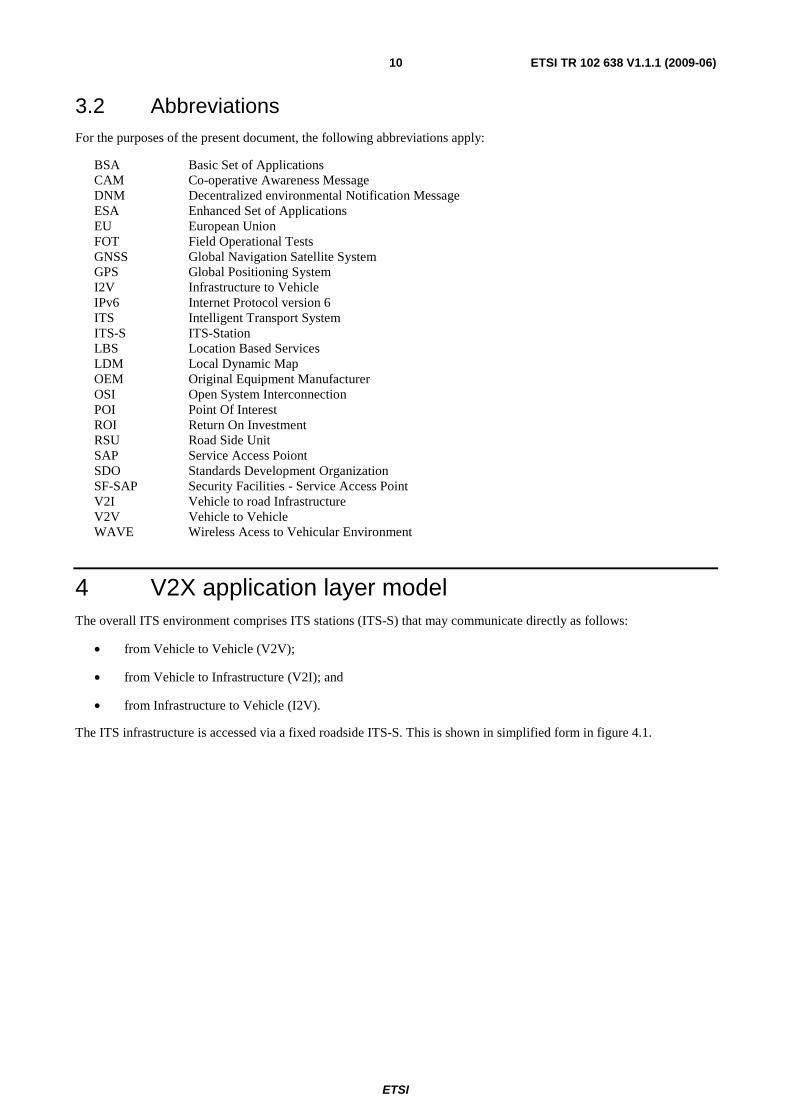
3.2 Abbreviations For the purposes of the present document, the following abbreviations apply:
BSA Basic Set of Applications CAM Co-operative Awareness Message DNM Decentralized environmental Notification Message ESA Enhanced Set of Applications EU European Union FOT Field Operational Tests GNSS Global Navigation Satellite System GPS Global Positioning System I2V Infrastructure to Vehicle IPv6 Internet Protocol version 6 ITS Intelligent Transport System ITS-S ITS-Station LBS Location Based Services LDM Local Dynamic Map OEM Original Equipment Manufacturer OSI Open System Interconnection POI Point Of Interest ROI Return On Investment RSU Road Side Unit SAP Service Access Poiont SDO Standards Development Organization SF-SAP Security Facilities - Service Access Point V2I Vehicle to road Infrastructure V2V Vehicle to Vehicle WAVE Wireless Acess to Vehicular Environment
4 V2X application layer model The overall ITS environment comprises ITS stations (ITS-S) that may communicate directly as follows:
• from Vehicle to Vehicle (V2V);
• from Vehicle to Infrastructure (V2I); and
• from Infrastructure to Vehicle (I2V).
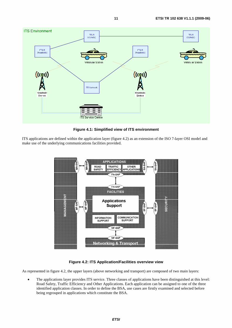
The ITS infrastructure is accessed via a fixed roadside ITS-S. This is shown in simplified form in figure 4.1.
ETSI
ETSI TR 102 638 V1.1.1 (2009-06) 11
Figure 4.1: Simplified view of ITS environment
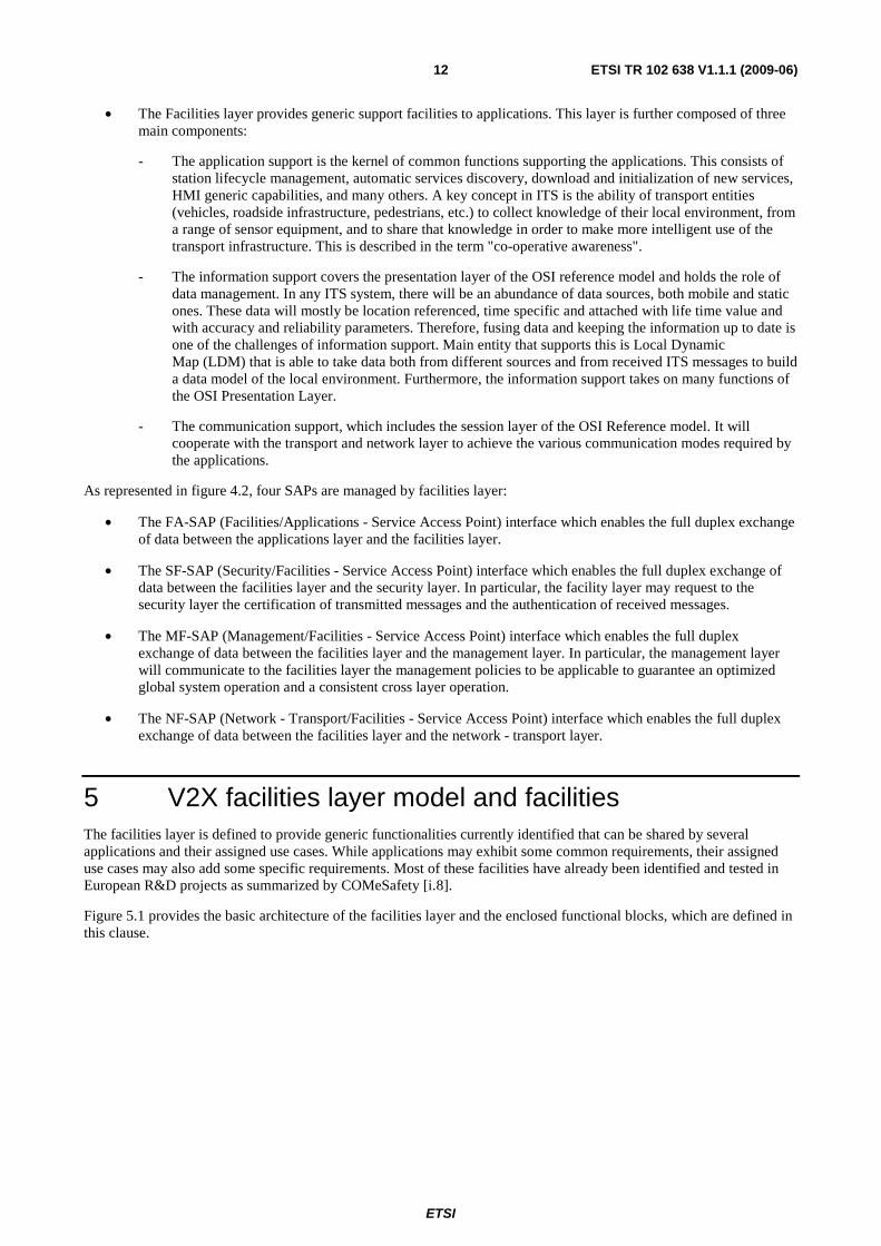
ITS applications are defined within the application layer (figure 4.2) as an extension of the ISO 7-layer OSI model and make use of the underlying communications facilities provided.
Figure 4.2: ITS Application/Facilities overview view
As represented in figure 4.2, the upper layers (above networking and transport) are composed of two main layers:
• The applications layer provides ITS service. Three classes of applications have been distinguished at this level: Road Safety, Traffic Efficiency and Other Applications. Each application can be assigned to one of the three identified application classes. In order to define the BSA, use cases are firstly examined and selected before being regrouped in applications which constitute the BSA.
ETSI
ETSI TR 102 638 V1.1.1 (2009-06) 12
• The Facilities layer provides generic support facilities to applications. This layer is further composed of three main components:
- The application support is the kernel of common functions supporting the applications. This consists of station lifecycle management, automatic services discovery, download and initialization of new services, HMI generic capabilities, and many others. A key concept in ITS is the ability of transport entities (vehicles, roadside infrastructure, pedestrians, etc.) to collect knowledge of their local environment, from a range of sensor equipment, and to share that knowledge in order to make more intelligent use of the transport infrastructure. This is described in the term "co-operative awareness".
- The information support covers the presentation layer of the OSI reference model and holds the role of data management. In any ITS system, there will be an abundance of data sources, both mobile and static ones. These data will mostly be location referenced, time specific and attached with life time value and with accuracy and reliability parameters. Therefore, fusing data and keeping the information up to date is one of the challenges of information support. Main entity that supports this is Local Dynamic Map (LDM) that is able to take data both from different sources and from received ITS messages to build a data model of the local environment. Furthermore, the information support takes on many functions of the OSI Presentation Layer.
- The communication support, which includes the session layer of the OSI Reference model. It will cooperate with the transport and network layer to achieve the various communication modes required by the applications.
As represented in figure 4.2, four SAPs are managed by facilities layer:
• The FA-SAP (Facilities/Applications - Service Access Point) interface which enables the full duplex exchange of data between the applications layer and the facilities layer.
• The SF-SAP (Security/Facilities - Service Access Point) interface which enables the full duplex exchange of data between the facilities layer and the security layer. In particular, the facility layer may request to the security layer the certification of transmitted messages and the authentication of received messages.
• The MF-SAP (Management/Facilities - Service Access Point) interface which enables the full duplex exchange of data between the facilities layer and the management layer. In particular, the management layer will communicate to the facilities layer the management policies to be applicable to guarantee an optimized global system operation and a consistent cross layer operation.
• The NF-SAP (Network - Transport/Facilities - Service Access Point) interface which enables the full duplex exchange of data between the facilities layer and the network - transport layer.
5 V2X facilities layer model and facilities The facilities layer is defined to provide generic functionalities currently identified that can be shared by several applications and their assigned use cases. While applications may exhibit some common requirements, their assigned use cases may also add some specific requirements. Most of these facilities have already been identified and tested in European R&D projects as summarized by COMeSafety [i.8].
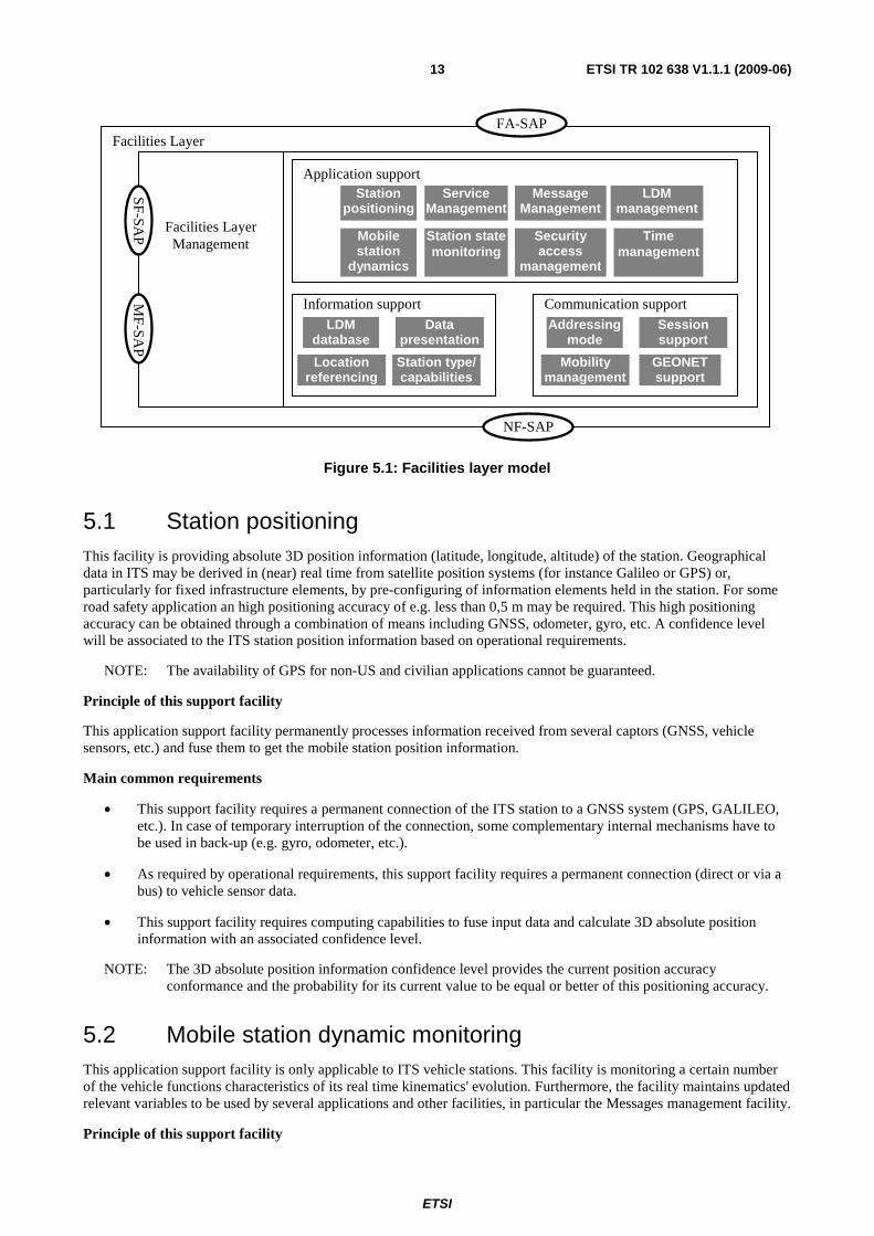
Figure 5.1 provides the basic architecture of the facilities layer and the enclosed functional blocks, which are defined in this clause.
ETSI
ETSI TR 102 638 V1.1.1 (2009-06) 13
Figure 5.1: Facilities layer model
5.1 Station positioning This facility is providing absolute 3D position information (latitude, longitude, altitude) of the station. Geographical data in ITS may be derived in (near) real time from satellite position systems (for instance Galileo or GPS) or, particularly for fixed infrastructure elements, by pre-configuring of information elements held in the station. For some road safety application an high positioning accuracy of e.g. less than 0,5 m may be required. This high positioning accuracy can be obtained through a combination of means including GNSS, odometer, gyro, etc. A confidence level will be associated to the ITS station position information based on operational requirements.
NOTE: The availability of GPS for non-US and civilian applications cannot be guaranteed.
Principle of this support facility
This application support facility permanently processes information received from several captors (GNSS, vehicle sensors, etc.) and fuse them to get the mobile station position information.
Main common requirements
• This support facility requires a permanent connection of the ITS station to a GNSS system (GPS, GALILEO, etc.). In case of temporary interruption of the connection, some complementary internal mechanisms have to be used in back-up (e.g. gyro, odometer, etc.).
• As required by operational requirements, this support facility requires a permanent connection (direct or via a bus) to vehicle sensor data.
• This support facility requires computing capabilities to fuse input data and calculate 3D absolute position information with an associated confidence level.
NOTE: The 3D absolute position information confidence level provides the current position accuracy conformance and the probability for its current value to be equal or better of this positioning accuracy.
5.2 Mobile station dynamic monitoring This application support facility is only applicable to ITS vehicle stations. This facility is monitoring a certain number of the vehicle functions characteristics of its real time kinematics' evolution. Furthermore, the facility maintains updated relevant variables to be used by several applications and other facilities, in particular the Messages management facility.
Principle of this support facility
.
Facilities Layer
Facilities Layer Management
Application support
Communication support
FA-SAP
NF-SAP
MF-SA
P
Station positioning
Service Management
Message Management
LDM management
Mobile station
dynamics
Station state monitoring
Security access
management
Time management
Information support
SF-SAP
LDM database
Data presentation
Location referencing
Station type/ capabilities
Addressing mode
Session support
Mobility management
GEONET support
ETSI
ETSI TR 102 638 V1.1.1 (2009-06) 14
This application support facility monitors permanently the real time evolutions of relevant vehicle electronic information either directly or through some in vehicle network. This facility further filters necessary variables allowing the update of the vehicle dynamic parameters.
Main common requirements
• This support facility requires access to vehicle functions according to selected options (e.g. braking system, steering system, tyre pressure monitoring system, stability control system, speed control, etc.).
• This support facility requires capabilities to filter the selected parameters being needed by applications and other facilities (e.g. master cylinder pressure, steering wheel angle, steering wheel angle rate of change, programmed speed control value, stability control status, yaw rate, vehicle speed, acceleration control, etc.).
• This support facility requires capabilities to update parameters values being used for CAM.
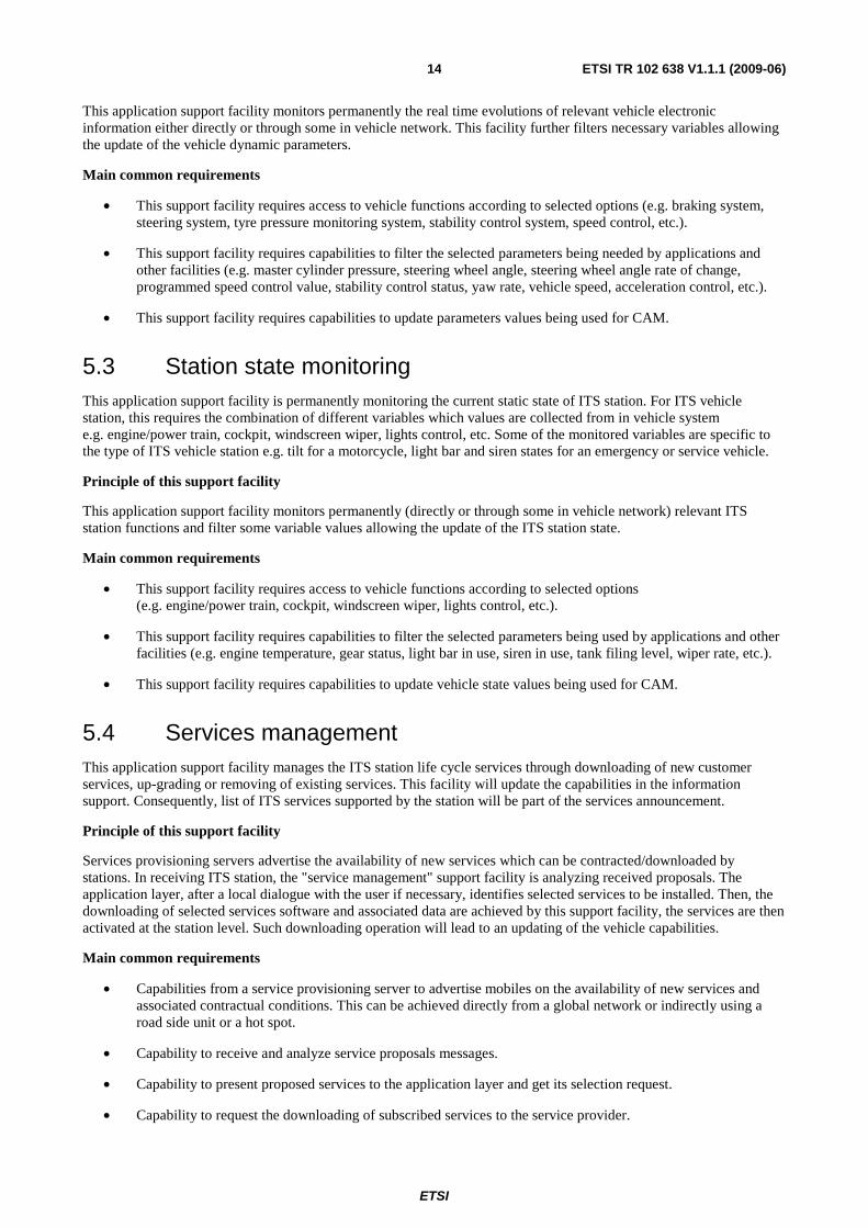
5.3 Station state monitoring This application support facility is permanently monitoring the current static state of ITS station. For ITS vehicle station, this requires the combination of different variables which values are collected from in vehicle system e.g. engine/power train, cockpit, windscreen wiper, lights control, etc. Some of the monitored variables are specific to the type of ITS vehicle station e.g. tilt for a motorcycle, light bar and siren states for an emergency or service vehicle.
Principle of this support facility
This application support facility monitors permanently (directly or through some in vehicle network) relevant ITS station functions and filter some variable values allowing the update of the ITS station state.
Main common requirements
• This support facility requires access to vehicle functions according to selected options (e.g. engine/power train, cockpit, windscreen wiper, lights control, etc.).
• This support facility requires capabilities to filter the selected parameters being used by applications and other facilities (e.g. engine temperature, gear status, light bar in use, siren in use, tank filing level, wiper rate, etc.).
• This support facility requires capabilities to update vehicle state values being used for CAM.
5.4 Services management This application support facility manages the ITS station life cycle services through downloading of new customer services, up-grading or removing of existing services. This facility will update the capabilities in the information support. Consequently, list of ITS services supported by the station will be part of the services announcement.
Principle of this support facility
Services provisioning servers advertise the availability of new services which can be contracted/downloaded by stations. In receiving ITS station, the "service management" support facility is analyzing received proposals. The application layer, after a local dialogue with the user if necessary, identifies selected services to be installed. Then, the downloading of selected services software and associated data are achieved by this support facility, the services are then activated at the station level. Such downloading operation will lead to an updating of the vehicle capabilities.
Main common requirements
• Capabilities from a service provisioning server to advertise mobiles on the availability of new services and associated contractual conditions. This can be achieved directly from a global network or indirectly using a road side unit or a hot spot.
• Capability to receive and analyze service proposals messages.
• Capability to present proposed services to the application layer and get its selection request.
• Capability to request the downloading of subscribed services to the service provider.
ETSI
ETSI TR 102 638 V1.1.1 (2009-06) 15
• Capability to download, integrate and activate the software associated to subscribed services.
• Capability to update an application with a new version due to new functionality or bug fixing.
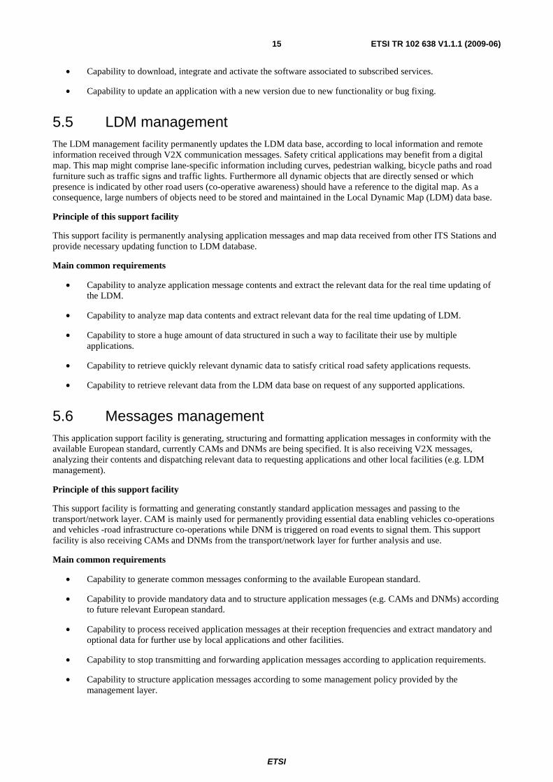
5.5 LDM management The LDM management facility permanently updates the LDM data base, according to local information and remote information received through V2X communication messages. Safety critical applications may benefit from a digital map. This map might comprise lane-specific information including curves, pedestrian walking, bicycle paths and road furniture such as traffic signs and traffic lights. Furthermore all dynamic objects that are directly sensed or which presence is indicated by other road users (co-operative awareness) should have a reference to the digital map. As a consequence, large numbers of objects need to be stored and maintained in the Local Dynamic Map (LDM) data base.
Principle of this support facility
This support facility is permanently analysing application messages and map data received from other ITS Stations and provide necessary updating function to LDM database.
Main common requirements
• Capability to analyze application message contents and extract the relevant data for the real time updating of the LDM.
• Capability to analyze map data contents and extract relevant data for the real time updating of LDM.
• Capability to store a huge amount of data structured in such a way to facilitate their use by multiple applications.
• Capability to retrieve quickly relevant dynamic data to satisfy critical road safety applications requests.
• Capability to retrieve relevant data from the LDM data base on request of any supported applications.
5.6 Messages management This application support facility is generating, structuring and formatting application messages in conformity with the available European standard, currently CAMs and DNMs are being specified. It is also receiving V2X messages, analyzing their contents and dispatching relevant data to requesting applications and other local facilities (e.g. LDM management).
Principle of this support facility
This support facility is formatting and generating constantly standard application messages and passing to the transport/network layer. CAM is mainly used for permanently providing essential data enabling vehicles co-operations and vehicles -road infrastructure co-operations while DNM is triggered on road events to signal them. This support facility is also receiving CAMs and DNMs from the transport/network layer for further analysis and use.
Main common requirements
• Capability to generate common messages conforming to the available European standard.
• Capability to provide mandatory data and to structure application messages (e.g. CAMs and DNMs) according to future relevant European standard.
• Capability to process received application messages at their reception frequencies and extract mandatory and optional data for further use by local applications and other facilities.
• Capability to stop transmitting and forwarding application messages according to application requirements.
• Capability to structure application messages according to some management policy provided by the management layer.
ETSI
ETSI TR 102 638 V1.1.1 (2009-06) 16
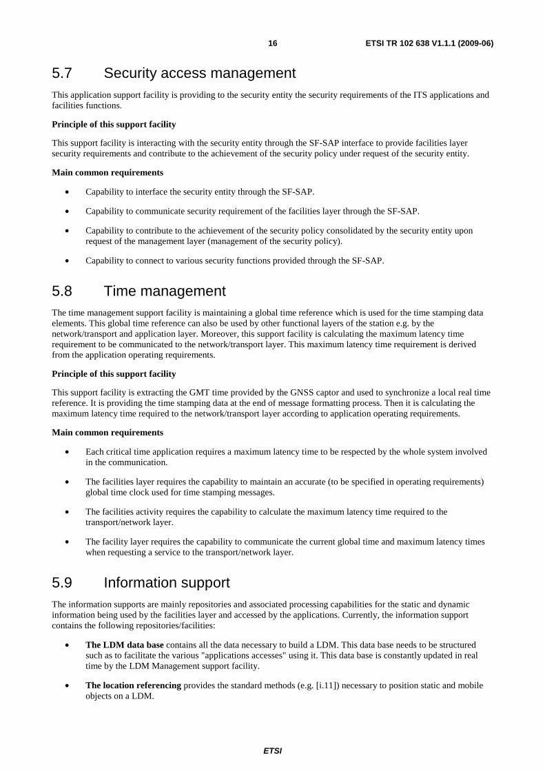
5.7 Security access management This application support facility is providing to the security entity the security requirements of the ITS applications and facilities functions.
Principle of this support facility
This support facility is interacting with the security entity through the SF-SAP interface to provide facilities layer security requirements and contribute to the achievement of the security policy under request of the security entity.
Main common requirements
• Capability to interface the security entity through the SF-SAP.
• Capability to communicate security requirement of the facilities layer through the SF-SAP.
• Capability to contribute to the achievement of the security policy consolidated by the security entity upon request of the management layer (management of the security policy).
• Capability to connect to various security functions provided through the SF-SAP.
5.8 Time management The time management support facility is maintaining a global time reference which is used for the time stamping data elements. This global time reference can also be used by other functional layers of the station e.g. by the network/transport and application layer. Moreover, this support facility is calculating the maximum latency time requirement to be communicated to the network/transport layer. This maximum latency time requirement is derived from the application operating requirements.
Principle of this support facility
This support facility is extracting the GMT time provided by the GNSS captor and used to synchronize a local real time reference. It is providing the time stamping data at the end of message formatting process. Then it is calculating the maximum latency time required to the network/transport layer according to application operating requirements.
Main common requirements
• Each critical time application requires a maximum latency time to be respected by the whole system involved in the communication.
• The facilities layer requires the capability to maintain an accurate (to be specified in operating requirements) global time clock used for time stamping messages.
• The facilities activity requires the capability to calculate the maximum latency time required to the transport/network layer.
• The facility layer requires the capability to communicate the current global time and maximum latency times when requesting a service to the transport/network layer.
5.9 Information support The information supports are mainly repositories and associated processing capabilities for the static and dynamic information being used by the facilities layer and accessed by the applications. Currently, the information support contains the following repositories/facilities:
• The LDM data base contains all the data necessary to build a LDM. This data base needs to be structured such as to facilitate the various "applications accesses" using it. This data base is constantly updated in real time by the LDM Management support facility.
• The location referencing provides the standard methods (e.g. [i.11]) necessary to position static and mobile objects on a LDM.
ETSI
ETSI TR 102 638 V1.1.1 (2009-06) 17
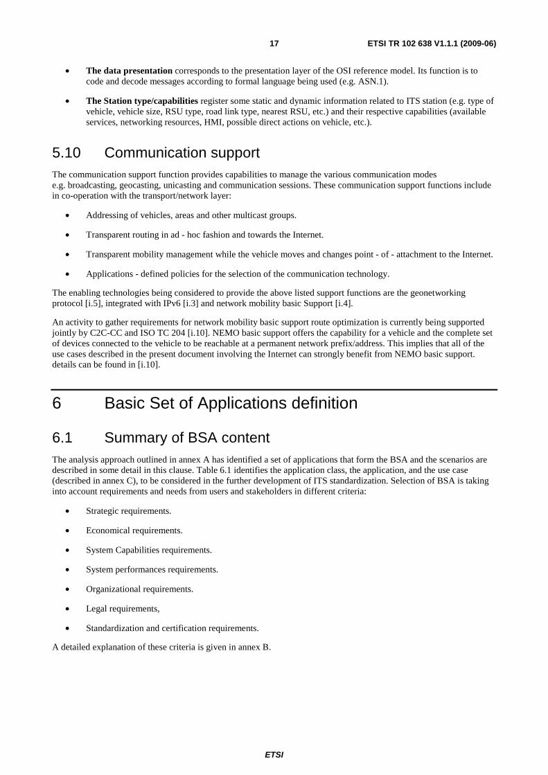
• The data presentation corresponds to the presentation layer of the OSI reference model. Its function is to code and decode messages according to formal language being used (e.g. ASN.1).
• The Station type/capabilities register some static and dynamic information related to ITS station (e.g. type of vehicle, vehicle size, RSU type, road link type, nearest RSU, etc.) and their respective capabilities (available services, networking resources, HMI, possible direct actions on vehicle, etc.).
5.10 Communication support The communication support function provides capabilities to manage the various communication modes e.g. broadcasting, geocasting, unicasting and communication sessions. These communication support functions include in co-operation with the transport/network layer:
• Addressing of vehicles, areas and other multicast groups.
• Transparent routing in ad - hoc fashion and towards the Internet.
• Transparent mobility management while the vehicle moves and changes point - of - attachment to the Internet.
• Applications - defined policies for the selection of the communication technology.
The enabling technologies being considered to provide the above listed support functions are the geonetworking protocol [i.5], integrated with IPv6 [i.3] and network mobility basic Support [i.4].
An activity to gather requirements for network mobility basic support route optimization is currently being supported jointly by C2C-CC and ISO TC 204 [i.10]. NEMO basic support offers the capability for a vehicle and the complete set of devices connected to the vehicle to be reachable at a permanent network prefix/address. This implies that all of the use cases described in the present document involving the Internet can strongly benefit from NEMO basic support. details can be found in [i.10].
6 Basic Set of Applications definition
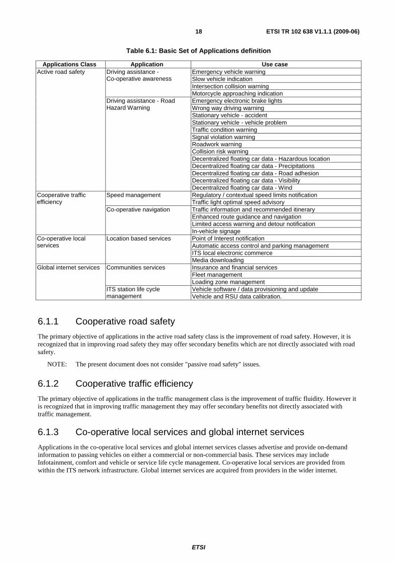
6.1 Summary of BSA content The analysis approach outlined in annex A has identified a set of applications that form the BSA and the scenarios are described in some detail in this clause. Table 6.1 identifies the application class, the application, and the use case (described in annex C), to be considered in the further development of ITS standardization. Selection of BSA is taking into account requirements and needs from users and stakeholders in different criteria:
• Strategic requirements.
• Economical requirements.
• System Capabilities requirements.
• System performances requirements.
• Organizational requirements.
• Legal requirements,
• Standardization and certification requirements.
A detailed explanation of these criteria is given in annex B.
ETSI
ETSI TR 102 638 V1.1.1 (2009-06) 18
Table 6.1: Basic Set of Applications definition
Applications Class Application Use case Active road safety Driving assistance -
Co-operative awareness Emergency vehicle warning Slow vehicle indication Intersection collision warning Motorcycle approaching indication
Driving assistance - Road Hazard Warning
Emergency electronic brake lights Wrong way driving warning Stationary vehicle - accident Stationary vehicle - vehicle problem Traffic condition warning Signal violation warning Roadwork warning Collision risk warning Decentralized floating car data - Hazardous location Decentralized floating car data - Precipitations Decentralized floating car data - Road adhesion Decentralized floating car data - Visibility Decentralized floating car data - Wind
Cooperative traffic efficiency
Speed management Regulatory / contextual speed limits notification Traffic light optimal speed advisory
Co-operative navigation Traffic information and recommended itinerary Enhanced route guidance and navigation Limited access warning and detour notification In-vehicle signage
Co-operative local services
Location based services Point of Interest notification Automatic access control and parking management ITS local electronic commerce Media downloading
Global internet services Communities services Insurance and financial services Fleet management Loading zone management
ITS station life cycle management
Vehicle software / data provisioning and update Vehicle and RSU data calibration.
6.1.1 Cooperative road safety
The primary objective of applications in the active road safety class is the improvement of road safety. However, it is recognized that in improving road safety they may offer secondary benefits which are not directly associated with road safety.
NOTE: The present document does not consider "passive road safety" issues.
6.1.2 Cooperative traffic efficiency
The primary objective of applications in the traffic management class is the improvement of traffic fluidity. However it is recognized that in improving traffic management they may offer secondary benefits not directly associated with traffic management.
6.1.3 Co-operative local services and global internet services
Applications in the co-operative local services and global internet services classes advertise and provide on-demand information to passing vehicles on either a commercial or non-commercial basis. These services may include Infotainment, comfort and vehicle or service life cycle management. Co-operative local services are provided from within the ITS network infrastructure. Global internet services are acquired from providers in the wider internet.
ETSI
ETSI TR 102 638 V1.1.1 (2009-06) 19
Annex A: BSA selection and assessment method
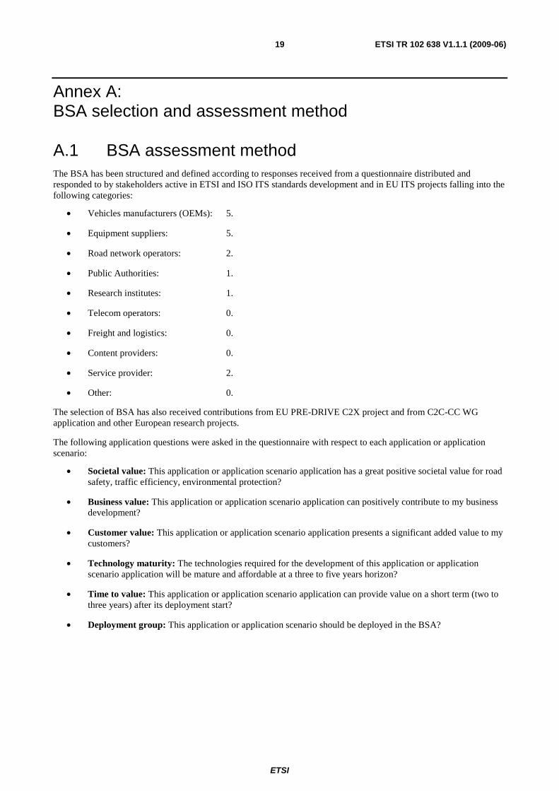
A.1 BSA assessment method The BSA has been structured and defined according to responses received from a questionnaire distributed and responded to by stakeholders active in ETSI and ISO ITS standards development and in EU ITS projects falling into the following categories:
• Vehicles manufacturers (OEMs): 5.
• Equipment suppliers: 5.
• Road network operators: 2.
• Public Authorities: 1.
• Research institutes: 1.
• Telecom operators: 0.
• Freight and logistics: 0.
• Content providers: 0.
• Service provider: 2.
• Other: 0.
The selection of BSA has also received contributions from EU PRE-DRIVE C2X project and from C2C-CC WG application and other European research projects.
The following application questions were asked in the questionnaire with respect to each application or application scenario:
• Societal value: This application or application scenario application has a great positive societal value for road safety, traffic efficiency, environmental protection?
• Business value: This application or application scenario application can positively contribute to my business development?
• Customer value: This application or application scenario application presents a significant added value to my customers?
• Technology maturity: The technologies required for the development of this application or application scenario application will be mature and affordable at a three to five years horizon?
• Time to value: This application or application scenario application can provide value on a short term (two to three years) after its deployment start?
• Deployment group: This application or application scenario should be deployed in the BSA?
ETSI
ETSI TR 102 638 V1.1.1 (2009-06) 20
Each stakeholder was asked to provide their evaluation by answering each question using the 5 level scale of:
• strongly agree (++);
• agree (+);
• neither agree nor disagree (0);
• disagree (-);
• strongly disagree (--).
The definitions considered for the questions are given below:
• Societal value: The value of the application for the European community in terms of contribution to road safety, traffic efficiency and environmental protection.
• Business value: The value of the application for the supply chain stakeholders in terms of ROI and profitability. The business value may take into consideration the customer value (impacting the selling price) but also some extra value provided to the stakeholder for the optimization of its life cycle processes e.g. reducing the vehicle warranty costs, reducing the engineering costs, facilitating new services deployment etc.
• Technological maturity: The likelihood to have off the shelf equipment satisfying the functional specifications and performances necessary to achieve the considered application at a reasonable cost.
• Customer value: The value of the application for the targeted customers in terms of its acceptable commercial price.
• Time to value: The time necessary to obtain the conditions required for the application to provide the expected customer value. This time is depending on the used deployment strategy and the minimum deployment threshold required to reach the customer expected value.
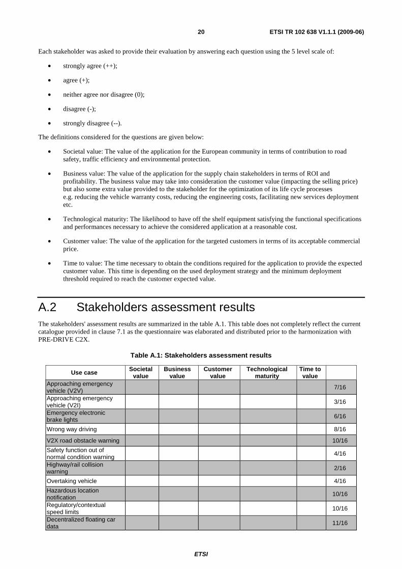
A.2 Stakeholders assessment results The stakeholders' assessment results are summarized in the table A.1. This table does not completely reflect the current catalogue provided in clause 7.1 as the questionnaire was elaborated and distributed prior to the harmonization with PRE-DRIVE C2X.
Table A.1: Stakeholders assessment results
Use case Societal value
Business value
Customer value
Technological maturity
Time to value
Approaching emergency vehicle (V2V) 7/16
Approaching emergency vehicle (V2I) 3/16
Emergency electronic brake lights 6/16
Wrong way driving 8/16
V2X road obstacle warning 10/16
Safety function out of normal condition warning 4/16
Highway/rail collision warning 2/16
Overtaking vehicle 4/16
Hazardous location notification 10/16
Regulatory/contextual speed limits 10/16
Decentralized floating car data 11/16
ETSI
ETSI TR 102 638 V1.1.1 (2009-06) 21
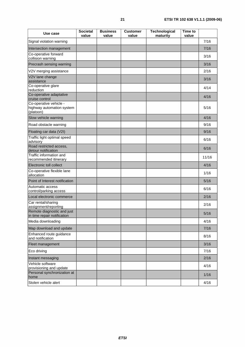
Use case Societal value
Business value
Customer value
Technological maturity
Time to value
Signal violation warning 7/16
Intersection management 7/16
Co-operative forward collision warning 3/16
Precrash sensing warning 3/16
V2V merging assistance 2/16
V2V lane change assistance 3/16
Co-operative glare reduction 4/14
Co-operative adaptative cruise control 4/16
Co-operative vehicle - highway automation system (platoon)
5/16
Slow vehicle warning 4/16
Road obstacle warning 9/16
Floating car data (V2I) 9/16
Traffic light optimal speed advisory 6/16
Road restricted access, detour notification 6/16
Traffic information and recommended itinerary 11/16
Electronic toll collect 4/16
Co-operative flexible lane allocation 1/16
Point of Interest notification 5/16
Automatic access control/parking access 6/16
Local electronic commerce 2/16
Car rental/sharing assignment/reporting 2/16
Remote diagnostic and just in time repair notification 5/16
Media downloading 4/16
Map download and update 7/16
Enhanced route guidance and notification 8/16
Fleet management 3/16
Eco driving 7/16
Instant messaging 2/16
Vehicle software provisioning and update 4/16
Personal synchronization at home 1/16
Stolen vehicle alert 4/16
ETSI
ETSI TR 102 638 V1.1.1 (2009-06) 22
A.3 PRE-DRIVE V2X use cases selection The European project PRE-DRIVE C2X has been established mainly to prepare European Field Operational Tests (FOT). For this purpose, PRE-DRIVE C2X has been selecting sixteen use cases which have to be priority assessed during European Field Operational Tests. Such selection is considered very relevant as it reflects intentions and decisions taken by the automobile industry which is well represented in PRE-DRIVE C2X.
The 16 PRE-DRIVE C2X selected use cases are:
Road safety:
• Road work warning.
• Stop sign violation.
• Traffic jam ahead warning.
• Car breakdown warning.
• Slow vehicle warning.
• Approaching emergency vehicle.
Traffic efficiency management:
• In-vehicle signage.
• Regulatory and contextual speed limits.
• Traffic info and recommended itinerary.
• Limited access warning.
• Decentralized floating car data.
• Greenlight optimal speed advisory.
Other:
• Vehicle software provisioning and update.
• Fleet management.
• Local electronic commerce.
• Insurance and financial services.
ETSI
ETSI TR 102 638 V1.1.1 (2009-06) 23
Annex B: Users needs and requirements for the selection of the BSA The following clauses define the main user needs and requirements which have been considered for market introduction of a Basic Set of Applications expected for the period 2012 to 2015. These user needs and requirements have been identified in various European research projects and ITS organizations e.g. C2C-C Consortium.
B.1 Strategic requirements The co-operative ITS deployment strategy is fundamental for the delivery of societal services. The following requirements have to be taken into account for the selection of a well balanced BSA:
• Required minimum penetration threshold for the considered application and its assigned use cases be able to provide a usable, valuable customer' service.
• Time to reach the required minimum penetration threshold from the decided start of deployment. This time is of course very dependent on the deployment strategy followed by the concerned actors. This will be referred in the present document as "the time to value".
• European Commission, European member states strategies and requirements for the deployment of societal applications (road safety, traffic efficiency, environmental improvement, etc.).
B.2 Economical requirements The European society and its transport industries need to converge to a common societal / business model which is satisfactory for both parties. For this purpose, the following economical requirements have to be taken into account for the definition of the BSA:
• Societal economies associated to the considered application/assigned use case once reaching the required minimum penetration threshold.
• Perceived customer value of a service which will enable the estimation of the service sales price.
• Business value associated to the considered application/assigned use case once reaching the required minimum penetration threshold.
• Total business and societal economies/values which can be attributed to the whole Basic Set of Applications and its assigned use cases once the required minimum penetration threshold have been reached for all of them.
• Purchase and operating cost of the system required to support each considered application and the whole Basic Set of Applications.
• Time to get a global return on investment. This is strongly related to the decided deployment strategy and the constitution of the BSA.
B.3 System Capabilities requirements The availability of system technical capabilities will condition the selection of the co-operative ITS applications/use cases belonging to the basic set. Only the set of technical capabilities expected to be available during the period 2012 to 2015, at an affordable cost, have to be considered.
• Radio communication capabilities. This includes:
- The radio communication single hop coverage (distance, area).
ETSI
ETSI TR 102 638 V1.1.1 (2009-06) 24
- The radio communication frequency channels being used (for interoperability purpose).
- The available bandwidth and bit transfer rate.
- The radio communication channel robustness which can be characterized by its packet error rate.
- The contribution of the road infrastructure to compensate for signal propagation difficulties in areas populated by radio obstacles (trees, buildings, etc.).
• Network communication capabilities:
- Broadcasting capabilities.
- Multicasting capabilities.
- Ad-hoc networking capabilities.
- Geocasting capabilities.
- Unicasting capabilities.
- Congestion control capabilities.
- Messages priorities management capabilities.
- Channels/connectivity management capabilities.
- Capability to gain at least one IPv6 globally valid address for Internet - based applications.
- Transparent management of changes in the point-of-attachment to the Internet for all the involved in-vehicle devices.
• Vehicle absolute positioning capabilities:
- GNSS capabilities.
- Combined positioning capabilities.
• Other vehicles capabilities:
- Vehicle interface and sensors capabilities.
- Vehicle navigation capabilities.
• Vehicle communication security capabilities:
- Respect of life privacy.
- Confidentiality.
- Resistance to external attacks.
- Authenticity of received data.
- Data and system integrity, etc.
ETSI
ETSI TR 102 638 V1.1.1 (2009-06) 25
B.4 System performances requirements The availability of technical system performances will condition the selection of the applications/use cases belonging to the basic set. Only the set of technical performances expected to be available during the period 2012 to 2015, at a reasonable cost, need to be considered.
• Vehicle communication performances (maximum latency time, maximum round trip delays, etc.).
• Vehicle positioning performances (e.g. absolute position accuracy, relative position accuracy, map matching accuracy, etc.).
• Vehicle communication system reliability and dependability performances (radio coverage, BER, black zones, etc.).
• Security operation performances (signing and verifying messages and certificates), etc.
B.5 Organizational requirements The deployment of co-operative ITS needs the establishment of some common organization(s) justified by the following organizational requirements:
• Availability of a common, consistent applications and use cases naming repository.
• Availability of a common, consistent applications/use cases addresses directory.
• Availability of an IPv6 address allocation scheme usable for V2V/V2I communication.
• Availability of a suitable organization insuring the interoperability of ITS systems.
• Availability of a suitable organization providing support to security protection.
• Availability of a suitable organization insuring the distribution of global names and addresses in vehicles.
B.6 Legal requirements The deployment of co-operative ITS need to take into account European member states and European Commission laws and regulations such as reflected through the following requirements:
• Respect of customer' life privacy.
• Liability/responsibilities of actors.
• Lawful interception, etc.
B.7 Standardization and certification requirements The interoperability and expected quality of service of co-operative ITS need to take into account the following requirements:
• System standardization.
• ITS station standardization.
• Product / service conformance testing.
• System interoperability testing.
• System risk management.
ETSI
ETSI TR 102 638 V1.1.1 (2009-06) 26
Annex C: Illustration of ITS use case catalogue
C.1 Co-operative road safety
C.1.1 Vehicle status warnings
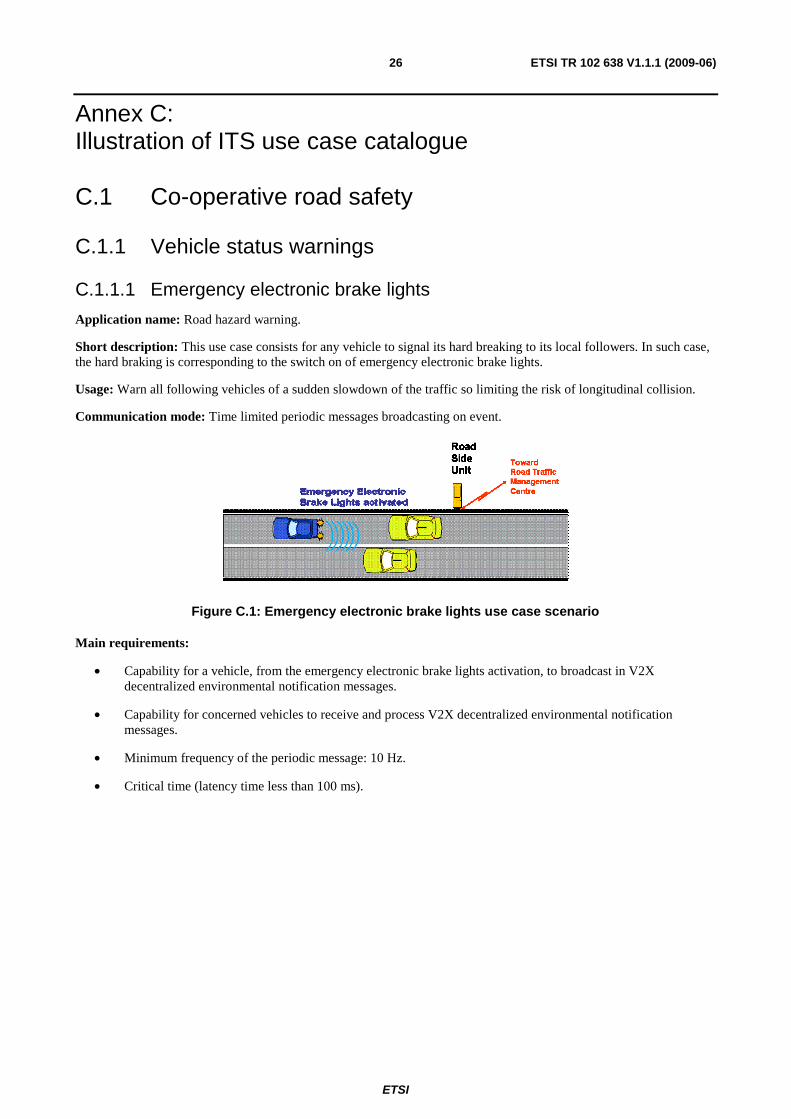
C.1.1.1 Emergency electronic brake lights
Application name: Road hazard warning.
Short description: This use case consists for any vehicle to signal its hard breaking to its local followers. In such case, the hard braking is corresponding to the switch on of emergency electronic brake lights.
Usage: Warn all following vehicles of a sudden slowdown of the traffic so limiting the risk of longitudinal collision.
Communication mode: Time limited periodic messages broadcasting on event.
Figure C.1: Emergency electronic brake lights use case scenario
Main requirements:
• Capability for a vehicle, from the emergency electronic brake lights activation, to broadcast in V2X decentralized environmental notification messages.
• Capability for concerned vehicles to receive and process V2X decentralized environmental notification messages.
• Minimum frequency of the periodic message: 10 Hz.
• Critical time (latency time less than 100 ms).
ETSI
ETSI TR 102 638 V1.1.1 (2009-06) 27
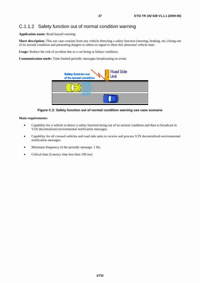
C.1.1.2 Safety function out of normal condition warning
Application name: Road hazard warning.
Short description: This use case consists from any vehicle detecting a safety function (steering, braking, etc.) being out of its normal condition and presenting dangers to others to signal to them this abnormal vehicle state.
Usage: Reduce the risk of accident due to a car being in failure condition.
Communication mode: Time limited periodic messages broadcasting on event.
Figure C.2: Safety function out of normal condition warning use case scenario
Main requirements:
• Capability for a vehicle to detect a safety function being out of its normal condition and then to broadcast in V2X decentralized environmental notification messages.
• Capability for all crossed vehicles and road side units to receive and process V2X decentralized environmental notification messages.
• Minimum frequency of the periodic message: 1 Hz.
• Critical time (Latency time less than 100 ms).
ETSI
ETSI TR 102 638 V1.1.1 (2009-06) 28
C.1.2 Vehicle type warnings
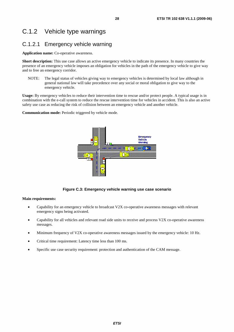
C.1.2.1 Emergency vehicle warning
Application name: Co-operative awareness.
Short description: This use case allows an active emergency vehicle to indicate its presence. In many countries the presence of an emergency vehicle imposes an obligation for vehicles in the path of the emergency vehicle to give way and to free an emergency corridor.
NOTE: The legal status of vehicles giving way to emergency vehicles is determined by local law although in general national law will take precedence over any social or moral obligation to give way to the emergency vehicle.
Usage: By emergency vehicles to reduce their intervention time to rescue and/or protect people. A typical usage is in combination with the e-call system to reduce the rescue intervention time for vehicles in accident. This is also an active safety use case as reducing the risk of collision between an emergency vehicle and another vehicle.
Communication mode: Periodic triggered by vehicle mode.
Figure C.3: Emergency vehicle warning use case scenario
Main requirements:
• Capability for an emergency vehicle to broadcast V2X co-operative awareness messages with relevant emergency signs being activated.
• Capability for all vehicles and relevant road side units to receive and process V2X co-operative awareness messages.
• Minimum frequency of V2X co-operative awareness messages issued by the emergency vehicle: 10 Hz.
• Critical time requirement: Latency time less than 100 ms.
• Specific use case security requirement: protection and authentication of the CAM message.
ETSI
ETSI TR 102 638 V1.1.1 (2009-06) 29
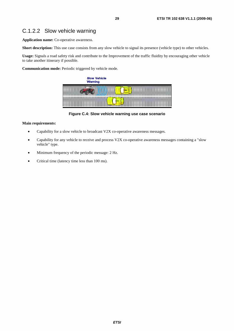
C.1.2.2 Slow vehicle warning
Application name: Co-operative awareness.
Short description: This use case consists from any slow vehicle to signal its presence (vehicle type) to other vehicles.
Usage: Signals a road safety risk and contribute to the Improvement of the traffic fluidity by encouraging other vehicle to take another itinerary if possible.
Communication mode: Periodic triggered by vehicle mode.
Figure C.4: Slow vehicle warning use case scenario
Main requirements:
• Capability for a slow vehicle to broadcast V2X co-operative awareness messages.
• Capability for any vehicle to receive and process V2X co-operative awareness messages containing a "slow vehicle" type.
• Minimum frequency of the periodic message: 2 Hz.
• Critical time (latency time less than 100 ms).
ETSI
ETSI TR 102 638 V1.1.1 (2009-06) 30
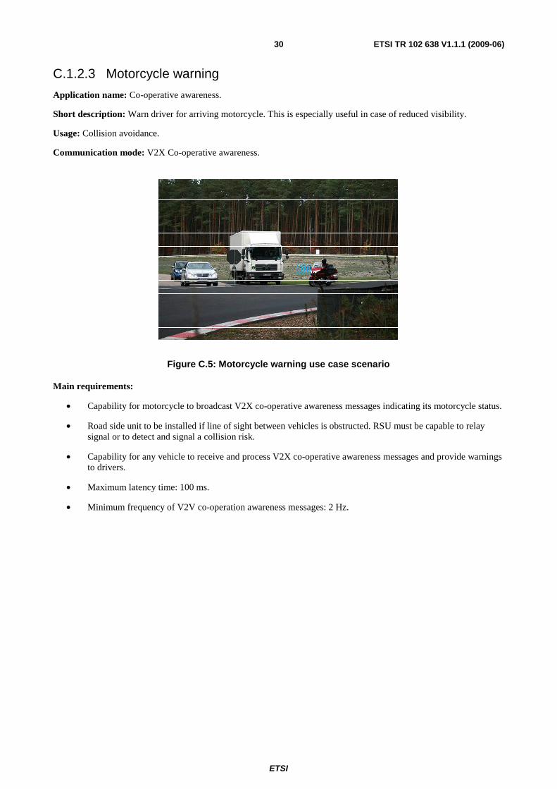
C.1.2.3 Motorcycle warning
Application name: Co-operative awareness.
Short description: Warn driver for arriving motorcycle. This is especially useful in case of reduced visibility.
Usage: Collision avoidance.
Communication mode: V2X Co-operative awareness.
Figure C.5: Motorcycle warning use case scenario
Main requirements:
• Capability for motorcycle to broadcast V2X co-operative awareness messages indicating its motorcycle status.
• Road side unit to be installed if line of sight between vehicles is obstructed. RSU must be capable to relay signal or to detect and signal a collision risk.
• Capability for any vehicle to receive and process V2X co-operative awareness messages and provide warnings to drivers.
• Maximum latency time: 100 ms.
• Minimum frequency of V2V co-operation awareness messages: 2 Hz.
ETSI
ETSI TR 102 638 V1.1.1 (2009-06) 31
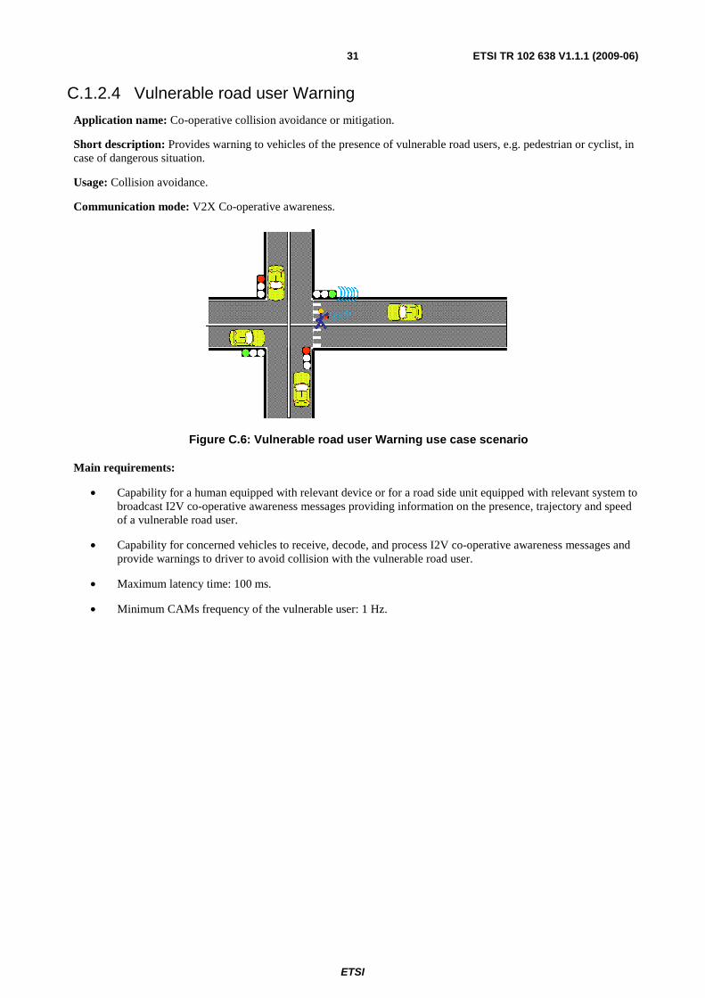
C.1.2.4 Vulnerable road user Warning
Application name: Co-operative collision avoidance or mitigation.
Short description: Provides warning to vehicles of the presence of vulnerable road users, e.g. pedestrian or cyclist, in case of dangerous situation.
Usage: Collision avoidance.
Communication mode: V2X Co-operative awareness.
Figure C.6: Vulnerable road user Warning use case scenario
Main requirements:
• Capability for a human equipped with relevant device or for a road side unit equipped with relevant system to broadcast I2V co-operative awareness messages providing information on the presence, trajectory and speed of a vulnerable road user.
• Capability for concerned vehicles to receive, decode, and process I2V co-operative awareness messages and provide warnings to driver to avoid collision with the vulnerable road user.
• Maximum latency time: 100 ms.
• Minimum CAMs frequency of the vulnerable user: 1 Hz.
ETSI
ETSI TR 102 638 V1.1.1 (2009-06) 32
C.1.3 Traffic hazard warnings
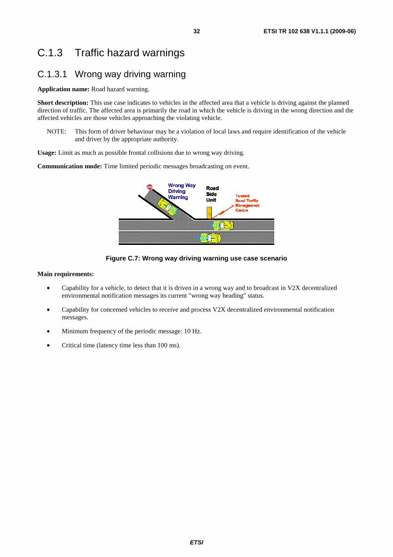
C.1.3.1 Wrong way driving warning
Application name: Road hazard warning.
Short description: This use case indicates to vehicles in the affected area that a vehicle is driving against the planned direction of traffic. The affected area is primarily the road in which the vehicle is driving in the wrong direction and the affected vehicles are those vehicles approaching the violating vehicle.
NOTE: This form of driver behaviour may be a violation of local laws and require identification of the vehicle and driver by the appropriate authority.
Usage: Limit as much as possible frontal collisions due to wrong way driving.
Communication mode: Time limited periodic messages broadcasting on event.
Figure C.7: Wrong way driving warning use case scenario
Main requirements:
• Capability for a vehicle, to detect that it is driven in a wrong way and to broadcast in V2X decentralized environmental notification messages its current "wrong way heading" status.
• Capability for concerned vehicles to receive and process V2X decentralized environmental notification messages.
• Minimum frequency of the periodic message: 10 Hz.
• Critical time (latency time less than 100 ms).
ETSI
ETSI TR 102 638 V1.1.1 (2009-06) 33
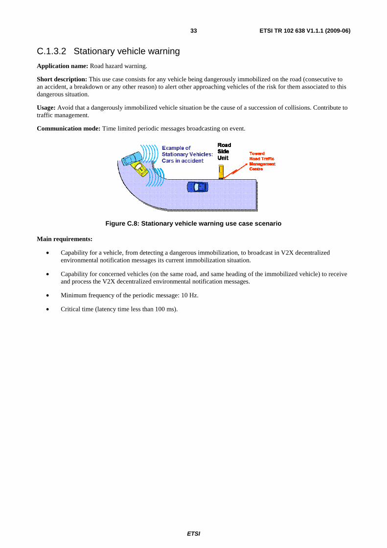
C.1.3.2 Stationary vehicle warning
Application name: Road hazard warning.
Short description: This use case consists for any vehicle being dangerously immobilized on the road (consecutive to an accident, a breakdown or any other reason) to alert other approaching vehicles of the risk for them associated to this dangerous situation.
Usage: Avoid that a dangerously immobilized vehicle situation be the cause of a succession of collisions. Contribute to traffic management.
Communication mode: Time limited periodic messages broadcasting on event.
Figure C.8: Stationary vehicle warning use case scenario
Main requirements:
• Capability for a vehicle, from detecting a dangerous immobilization, to broadcast in V2X decentralized environmental notification messages its current immobilization situation.
• Capability for concerned vehicles (on the same road, and same heading of the immobilized vehicle) to receive and process the V2X decentralized environmental notification messages.
• Minimum frequency of the periodic message: 10 Hz.
• Critical time (latency time less than 100 ms).
ETSI
ETSI TR 102 638 V1.1.1 (2009-06) 34
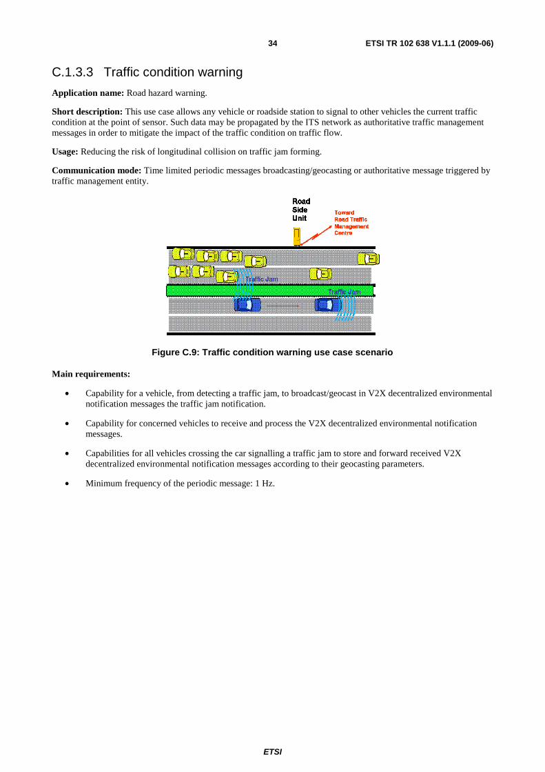
C.1.3.3 Traffic condition warning
Application name: Road hazard warning.
Short description: This use case allows any vehicle or roadside station to signal to other vehicles the current traffic condition at the point of sensor. Such data may be propagated by the ITS network as authoritative traffic management messages in order to mitigate the impact of the traffic condition on traffic flow.
Usage: Reducing the risk of longitudinal collision on traffic jam forming.
Communication mode: Time limited periodic messages broadcasting/geocasting or authoritative message triggered by traffic management entity.
Figure C.9: Traffic condition warning use case scenario
Main requirements:
• Capability for a vehicle, from detecting a traffic jam, to broadcast/geocast in V2X decentralized environmental notification messages the traffic jam notification.
• Capability for concerned vehicles to receive and process the V2X decentralized environmental notification messages.
• Capabilities for all vehicles crossing the car signalling a traffic jam to store and forward received V2X decentralized environmental notification messages according to their geocasting parameters.
• Minimum frequency of the periodic message: 1 Hz.
ETSI
ETSI TR 102 638 V1.1.1 (2009-06) 35
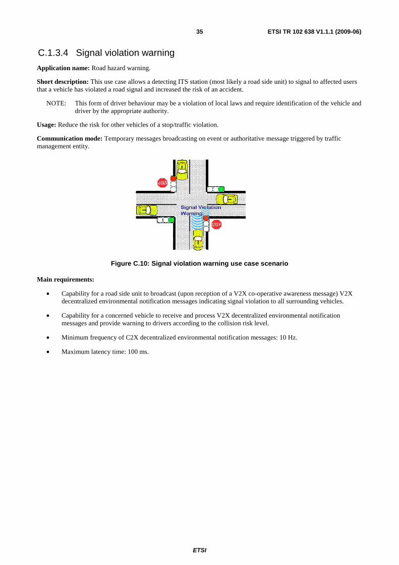
C.1.3.4 Signal violation warning
Application name: Road hazard warning.
Short description: This use case allows a detecting ITS station (most likely a road side unit) to signal to affected users that a vehicle has violated a road signal and increased the risk of an accident.
NOTE: This form of driver behaviour may be a violation of local laws and require identification of the vehicle and driver by the appropriate authority.
Usage: Reduce the risk for other vehicles of a stop/traffic violation.
Communication mode: Temporary messages broadcasting on event or authoritative message triggered by traffic management entity.
Figure C.10: Signal violation warning use case scenario
Main requirements:
• Capability for a road side unit to broadcast (upon reception of a V2X co-operative awareness message) V2X decentralized environmental notification messages indicating signal violation to all surrounding vehicles.
• Capability for a concerned vehicle to receive and process V2X decentralized environmental notification messages and provide warning to drivers according to the collision risk level.
• Minimum frequency of C2X decentralized environmental notification messages: 10 Hz.
• Maximum latency time: 100 ms.
ETSI
ETSI TR 102 638 V1.1.1 (2009-06) 36
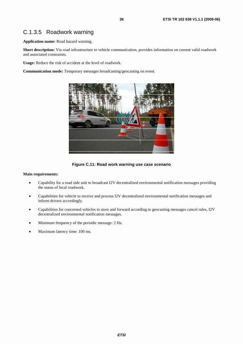
C.1.3.5 Roadwork warning
Application name: Road hazard warning.
Short description: Via road infrastructure to vehicle communication, provides information on current valid roadwork and associated constraints.
Usage: Reduce the risk of accident at the level of roadwork.
Communication mode: Temporary messages broadcasting/geocasting on event.
Figure C.11: Road work warning use case scenario
Main requirements:
• Capability for a road side unit to broadcast I2V decentralized environmental notification messages providing the status of local roadwork.
• Capabilities for vehicle to receive and process I2V decentralized environmental notification messages and inform drivers accordingly.
• Capabilities for concerned vehicles to store and forward according to geocasting messages cancel rules, I2V decentralized environmental notification messages.
• Minimum frequency of the periodic message: 2 Hz.
• Maximum latency time: 100 ms.
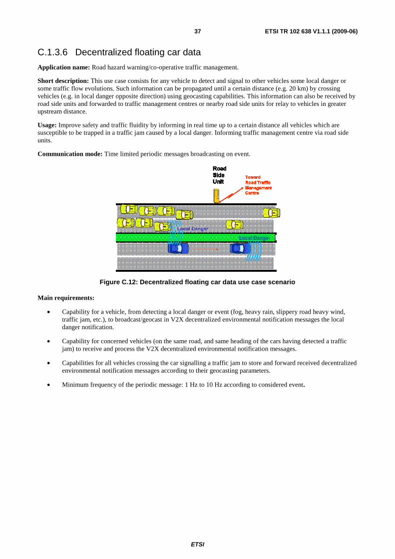
ETSI
ETSI TR 102 638 V1.1.1 (2009-06) 37
C.1.3.6 Decentralized floating car data
Application name: Road hazard warning/co-operative traffic management.
Short description: This use case consists for any vehicle to detect and signal to other vehicles some local danger or some traffic flow evolutions. Such information can be propagated until a certain distance (e.g. 20 km) by crossing vehicles (e.g. in local danger opposite direction) using geocasting capabilities. This information can also be received by road side units and forwarded to traffic management centres or nearby road side units for relay to vehicles in greater upstream distance.
Usage: Improve safety and traffic fluidity by informing in real time up to a certain distance all vehicles which are susceptible to be trapped in a traffic jam caused by a local danger. Informing traffic management centre via road side units.
Communication mode: Time limited periodic messages broadcasting on event.
Figure C.12: Decentralized floating car data use case scenario
Main requirements:
• Capability for a vehicle, from detecting a local danger or event (fog, heavy rain, slippery road heavy wind, traffic jam, etc.), to broadcast/geocast in V2X decentralized environmental notification messages the local danger notification.
• Capability for concerned vehicles (on the same road, and same heading of the cars having detected a traffic jam) to receive and process the V2X decentralized environmental notification messages.
• Capabilities for all vehicles crossing the car signalling a traffic jam to store and forward received decentralized environmental notification messages according to their geocasting parameters.
• Minimum frequency of the periodic message: 1 Hz to 10 Hz according to considered event.
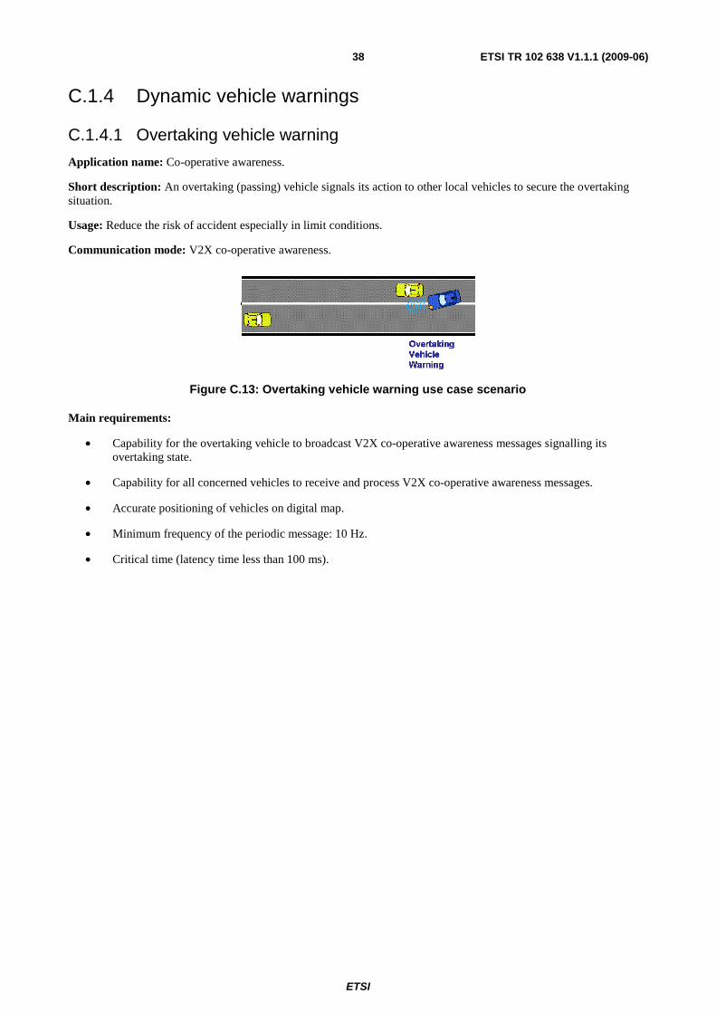
ETSI
ETSI TR 102 638 V1.1.1 (2009-06) 38
C.1.4 Dynamic vehicle warnings
C.1.4.1 Overtaking vehicle warning
Application name: Co-operative awareness.
Short description: An overtaking (passing) vehicle signals its action to other local vehicles to secure the overtaking situation.
Usage: Reduce the risk of accident especially in limit conditions.
Communication mode: V2X co-operative awareness.
Figure C.13: Overtaking vehicle warning use case scenario
Main requirements:
• Capability for the overtaking vehicle to broadcast V2X co-operative awareness messages signalling its overtaking state.
• Capability for all concerned vehicles to receive and process V2X co-operative awareness messages.
• Accurate positioning of vehicles on digital map.
• Minimum frequency of the periodic message: 10 Hz.
• Critical time (latency time less than 100 ms).
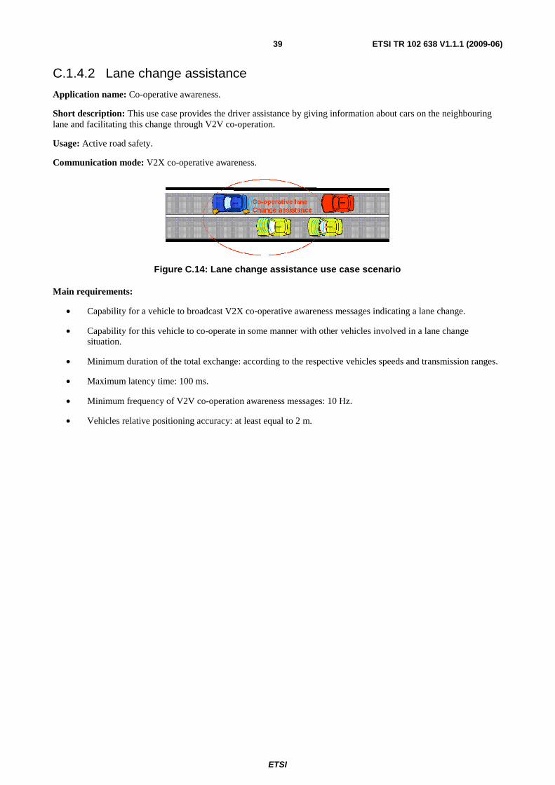
ETSI
ETSI TR 102 638 V1.1.1 (2009-06) 39
C.1.4.2 Lane change assistance
Application name: Co-operative awareness.
Short description: This use case provides the driver assistance by giving information about cars on the neighbouring lane and facilitating this change through V2V co-operation.
Usage: Active road safety.
Communication mode: V2X co-operative awareness.
Figure C.14: Lane change assistance use case scenario
Main requirements:
• Capability for a vehicle to broadcast V2X co-operative awareness messages indicating a lane change.
• Capability for this vehicle to co-operate in some manner with other vehicles involved in a lane change situation.
• Minimum duration of the total exchange: according to the respective vehicles speeds and transmission ranges.
• Maximum latency time: 100 ms.
• Minimum frequency of V2V co-operation awareness messages: 10 Hz.
• Vehicles relative positioning accuracy: at least equal to 2 m.
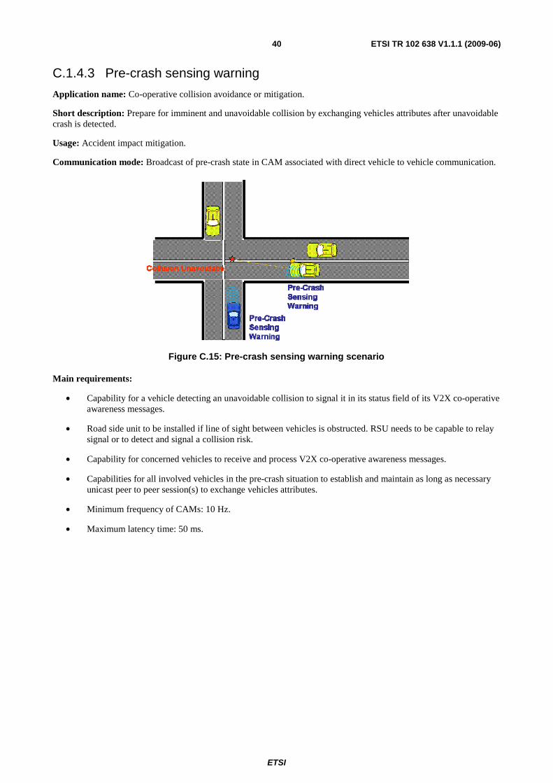
ETSI
ETSI TR 102 638 V1.1.1 (2009-06) 40
C.1.4.3 Pre-crash sensing warning
Application name: Co-operative collision avoidance or mitigation.
Short description: Prepare for imminent and unavoidable collision by exchanging vehicles attributes after unavoidable crash is detected.
Usage: Accident impact mitigation.
Communication mode: Broadcast of pre-crash state in CAM associated with direct vehicle to vehicle communication.
Figure C.15: Pre-crash sensing warning scenario
Main requirements:
• Capability for a vehicle detecting an unavoidable collision to signal it in its status field of its V2X co-operative awareness messages.
• Road side unit to be installed if line of sight between vehicles is obstructed. RSU needs to be capable to relay signal or to detect and signal a collision risk.
• Capability for concerned vehicles to receive and process V2X co-operative awareness messages.
• Capabilities for all involved vehicles in the pre-crash situation to establish and maintain as long as necessary unicast peer to peer session(s) to exchange vehicles attributes.
• Minimum frequency of CAMs: 10 Hz.
• Maximum latency time: 50 ms.
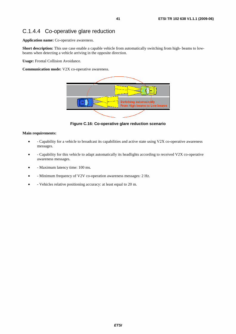
ETSI
ETSI TR 102 638 V1.1.1 (2009-06) 41
C.1.4.4 Co-operative glare reduction
Application name: Co-operative awareness.
Short description: This use case enable a capable vehicle from automatically switching from high- beams to low-beams when detecting a vehicle arriving in the opposite direction.
Usage: Frontal Collision Avoidance.
Communication mode: V2X co-operative awareness.
Figure C.16: Co-operative glare reduction scenario
Main requirements:
• - Capability for a vehicle to broadcast its capabilities and active state using V2X co-operative awareness messages.
• - Capability for this vehicle to adapt automatically its headlights according to received V2X co-operative awareness messages.
• - Maximum latency time: 100 ms.
• - Minimum frequency of V2V co-operation awareness messages: 2 Hz.
• - Vehicles relative positioning accuracy: at least equal to 20 m.
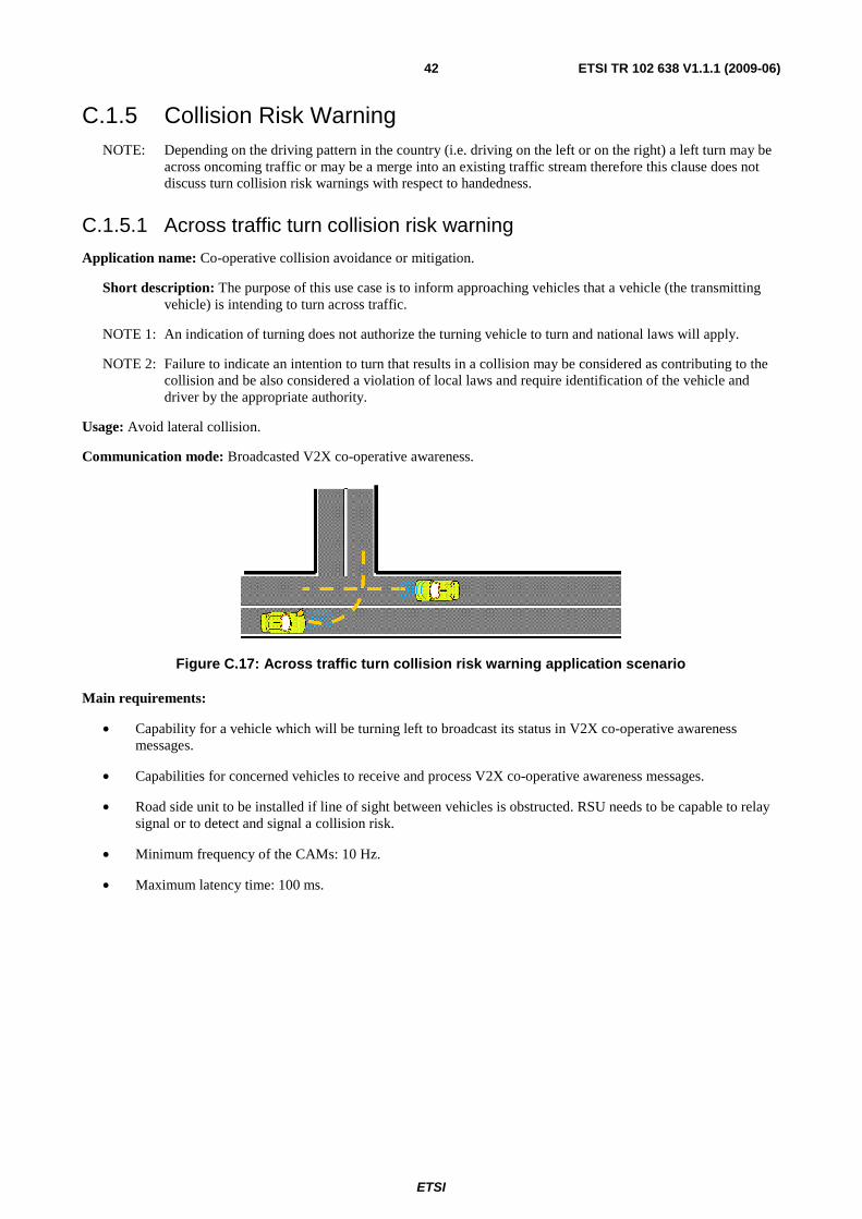
ETSI
ETSI TR 102 638 V1.1.1 (2009-06) 42
C.1.5 Collision Risk Warning NOTE: Depending on the driving pattern in the country (i.e. driving on the left or on the right) a left turn may be
across oncoming traffic or may be a merge into an existing traffic stream therefore this clause does not discuss turn collision risk warnings with respect to handedness.
C.1.5.1 Across traffic turn collision risk warning
Application name: Co-operative collision avoidance or mitigation.
Short description: The purpose of this use case is to inform approaching vehicles that a vehicle (the transmitting vehicle) is intending to turn across traffic.
NOTE 1: An indication of turning does not authorize the turning vehicle to turn and national laws will apply.
NOTE 2: Failure to indicate an intention to turn that results in a collision may be considered as contributing to the collision and be also considered a violation of local laws and require identification of the vehicle and driver by the appropriate authority.
Usage: Avoid lateral collision.
Communication mode: Broadcasted V2X co-operative awareness.
Figure C.17: Across traffic turn collision risk warning application scenario
Main requirements:
• Capability for a vehicle which will be turning left to broadcast its status in V2X co-operative awareness messages.
• Capabilities for concerned vehicles to receive and process V2X co-operative awareness messages.
• Road side unit to be installed if line of sight between vehicles is obstructed. RSU needs to be capable to relay signal or to detect and signal a collision risk.
• Minimum frequency of the CAMs: 10 Hz.
• Maximum latency time: 100 ms.
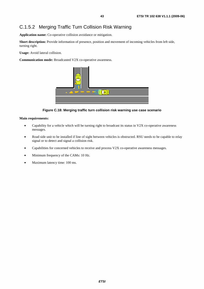
ETSI
ETSI TR 102 638 V1.1.1 (2009-06) 43
C.1.5.2 Merging Traffic Turn Collision Risk Warning
Application name: Co-operative collision avoidance or mitigation.
Short description: Provide information of presence, position and movement of incoming vehicles from left side, turning right.
Usage: Avoid lateral collision.
Communication mode: Broadcasted V2X co-operative awareness.
Figure C.18: Merging traffic turn collision risk warning use case scenario
Main requirements:
• Capability for a vehicle which will be turning right to broadcast its status in V2X co-operative awareness messages.
• Road side unit to be installed if line of sight between vehicles is obstructed. RSU needs to be capable to relay signal or to detect and signal a collision risk.
• Capabilities for concerned vehicles to receive and process V2X co-operative awareness messages.
• Minimum frequency of the CAMs: 10 Hz.
• Maximum latency time: 100 ms.
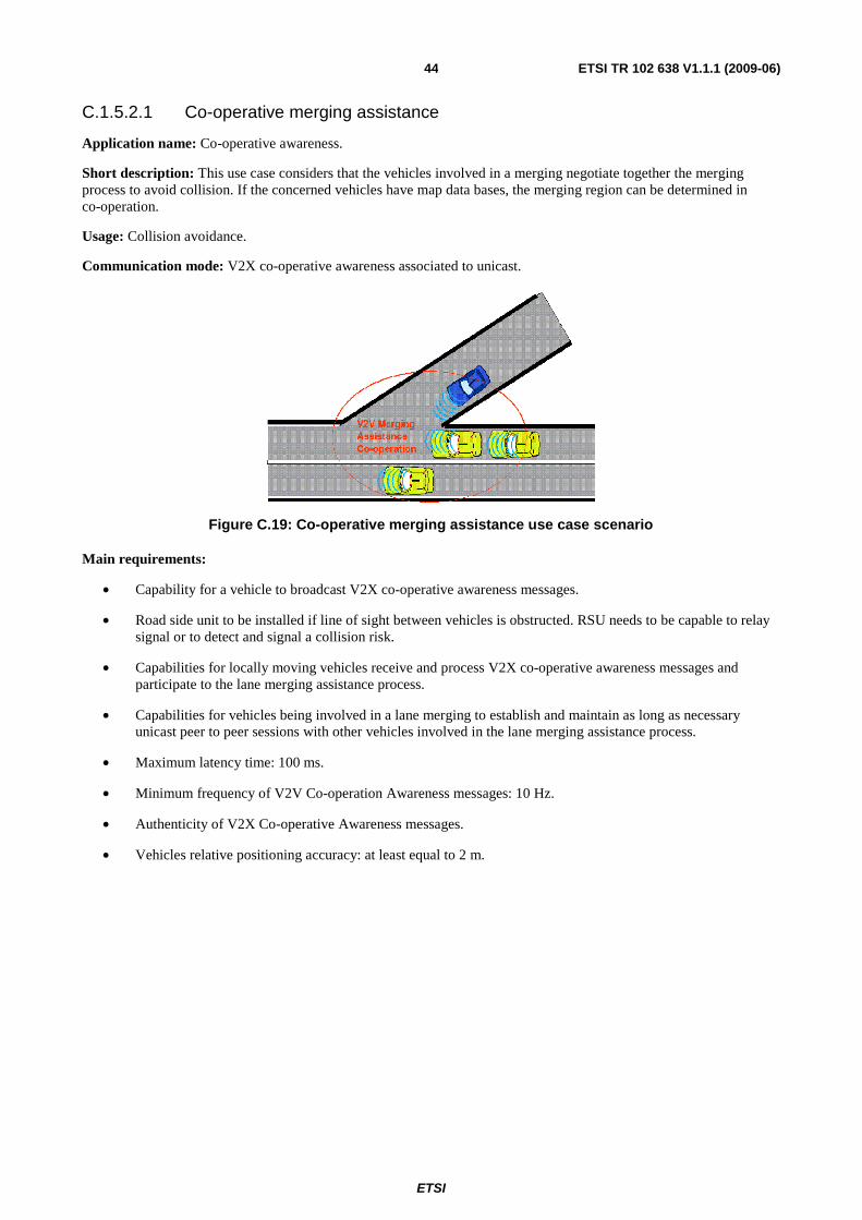
ETSI
ETSI TR 102 638 V1.1.1 (2009-06) 44
C.1.5.2.1 Co-operative merging assistance
Application name: Co-operative awareness.
Short description: This use case considers that the vehicles involved in a merging negotiate together the merging process to avoid collision. If the concerned vehicles have map data bases, the merging region can be determined in co-operation.
Usage: Collision avoidance.
Communication mode: V2X co-operative awareness associated to unicast.
Figure C.19: Co-operative merging assistance use case scenario
Main requirements:
• Capability for a vehicle to broadcast V2X co-operative awareness messages.
• Road side unit to be installed if line of sight between vehicles is obstructed. RSU needs to be capable to relay signal or to detect and signal a collision risk.
• Capabilities for locally moving vehicles receive and process V2X co-operative awareness messages and participate to the lane merging assistance process.
• Capabilities for vehicles being involved in a lane merging to establish and maintain as long as necessary unicast peer to peer sessions with other vehicles involved in the lane merging assistance process.
• Maximum latency time: 100 ms.
• Minimum frequency of V2V Co-operation Awareness messages: 10 Hz.
• Authenticity of V2X Co-operative Awareness messages.
• Vehicles relative positioning accuracy: at least equal to 2 m.
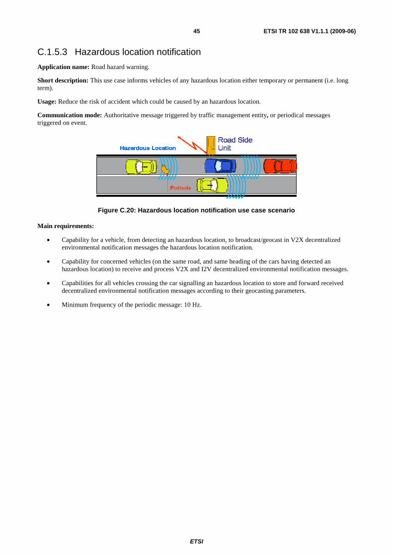
ETSI
ETSI TR 102 638 V1.1.1 (2009-06) 45
C.1.5.3 Hazardous location notification
Application name: Road hazard warning.
Short description: This use case informs vehicles of any hazardous location either temporary or permanent (i.e. long term).
Usage: Reduce the risk of accident which could be caused by an hazardous location.
Communication mode: Authoritative message triggered by traffic management entity, or periodical messages triggered on event.
Figure C.20: Hazardous location notification use case scenario
Main requirements:
• Capability for a vehicle, from detecting an hazardous location, to broadcast/geocast in V2X decentralized environmental notification messages the hazardous location notification.
• Capability for concerned vehicles (on the same road, and same heading of the cars having detected an hazardous location) to receive and process V2X and I2V decentralized environmental notification messages.
• Capabilities for all vehicles crossing the car signalling an hazardous location to store and forward received decentralized environmental notification messages according to their geocasting parameters.
• Minimum frequency of the periodic message: 10 Hz.
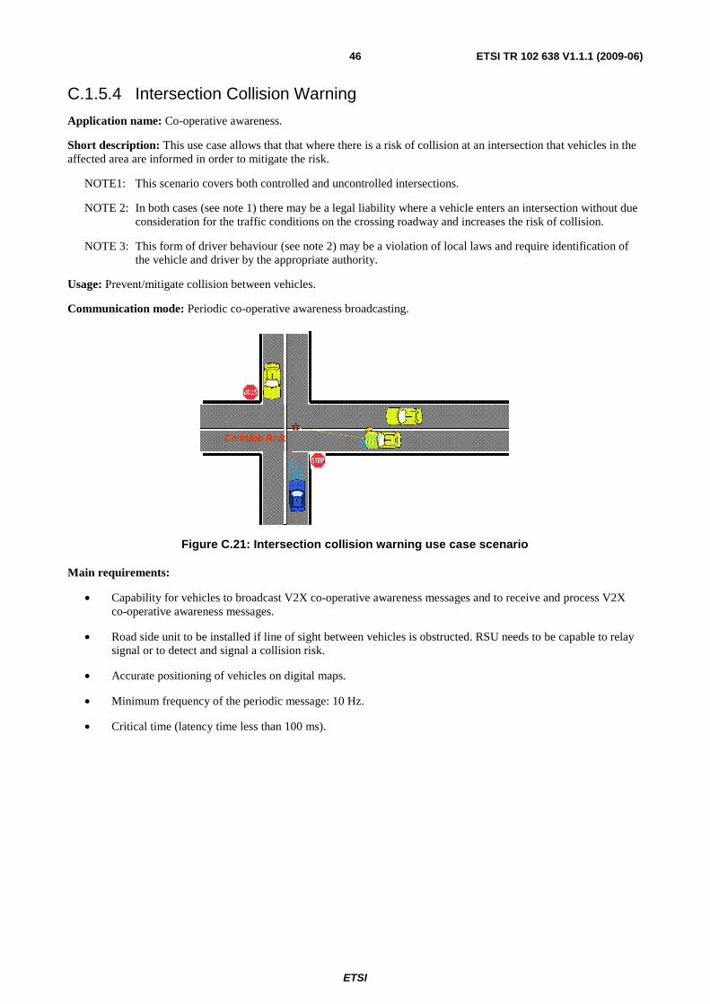
ETSI
ETSI TR 102 638 V1.1.1 (2009-06) 46
C.1.5.4 Intersection Collision Warning
Application name: Co-operative awareness.
Short description: This use case allows that that where there is a risk of collision at an intersection that vehicles in the affected area are informed in order to mitigate the risk.
NOTE1: This scenario covers both controlled and uncontrolled intersections.
NOTE 2: In both cases (see note 1) there may be a legal liability where a vehicle enters an intersection without due consideration for the traffic conditions on the crossing roadway and increases the risk of collision.
NOTE 3: This form of driver behaviour (see note 2) may be a violation of local laws and require identification of the vehicle and driver by the appropriate authority.
Usage: Prevent/mitigate collision between vehicles.
Communication mode: Periodic co-operative awareness broadcasting.
Figure C.21: Intersection collision warning use case scenario
Main requirements:
• Capability for vehicles to broadcast V2X co-operative awareness messages and to receive and process V2X co-operative awareness messages.
• Road side unit to be installed if line of sight between vehicles is obstructed. RSU needs to be capable to relay signal or to detect and signal a collision risk.
• Accurate positioning of vehicles on digital maps.
• Minimum frequency of the periodic message: 10 Hz.
• Critical time (latency time less than 100 ms).
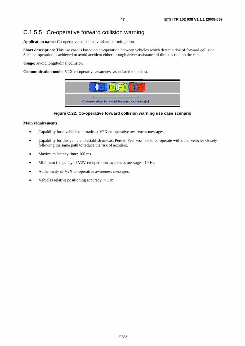
ETSI
ETSI TR 102 638 V1.1.1 (2009-06) 47
C.1.5.5 Co-operative forward collision warning
Application name: Co-operative collision avoidance or mitigation.
Short description: This use case is based on co-operation between vehicles which detect a risk of forward collision. Such co-operation is achieved to avoid accident either through driver assistance of direct action on the cars.
Usage: Avoid longitudinal collision.
Communication mode: V2X co-operative awareness associated to unicast.
Figure C.22: Co-operative forward collision warning use case scenario
Main requirements:
• Capability for a vehicle to broadcast V2X co-operative awareness messages.
• Capability for this vehicle to establish unicast Peer to Peer sessions to co-operate with other vehicles closely following the same path to reduce the risk of accident.
• Maximum latency time: 100 ms.
• Minimum frequency of V2V co-operation awareness messages: 10 Hz.
• Authenticity of V2X co-operative awareness messages.
• Vehicles relative positioning accuracy: < 1 m.
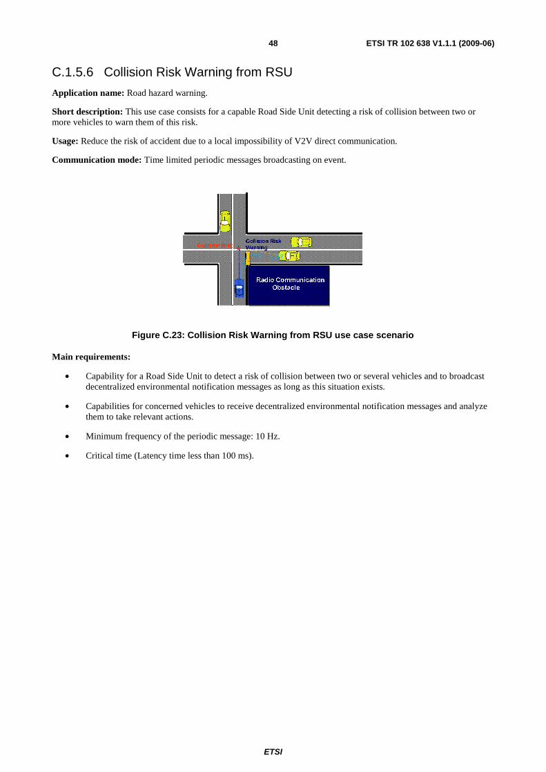
ETSI
ETSI TR 102 638 V1.1.1 (2009-06) 48
C.1.5.6 Collision Risk Warning from RSU
Application name: Road hazard warning.
Short description: This use case consists for a capable Road Side Unit detecting a risk of collision between two or more vehicles to warn them of this risk.
Usage: Reduce the risk of accident due to a local impossibility of V2V direct communication.
Communication mode: Time limited periodic messages broadcasting on event.
Figure C.23: Collision Risk Warning from RSU use case scenario
Main requirements:
• Capability for a Road Side Unit to detect a risk of collision between two or several vehicles and to broadcast decentralized environmental notification messages as long as this situation exists.
• Capabilities for concerned vehicles to receive decentralized environmental notification messages and analyze them to take relevant actions.
• Minimum frequency of the periodic message: 10 Hz.
• Critical time (Latency time less than 100 ms).
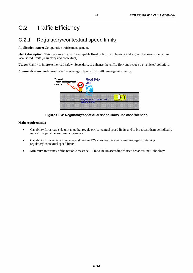
ETSI
ETSI TR 102 638 V1.1.1 (2009-06) 49
C.2 Traffic Efficiency
C.2.1 Regulatory/contextual speed limits Application name: Co-operative traffic management.
Short description: This use case consists for a capable Road Side Unit to broadcast at a given frequency the current local speed limits (regulatory and contextual).
Usage: Mainly to improve the road safety. Secondary, to enhance the traffic flow and reduce the vehicles' pollution.
Communication mode: Authoritative message triggered by traffic management entity.
Figure C.24: Regulatory/contextual speed limits use case scenario
Main requirements:
• Capability for a road side unit to gather regulatory/contextual speed limits and to broadcast them periodically in I2V co-operative awareness messages.
• Capability for a vehicle to receive and process I2V co-operative awareness messages containing regulatory/contextual speed limits.
• Minimum frequency of the periodic message: 1 Hz to 10 Hz according to used broadcasting technology.
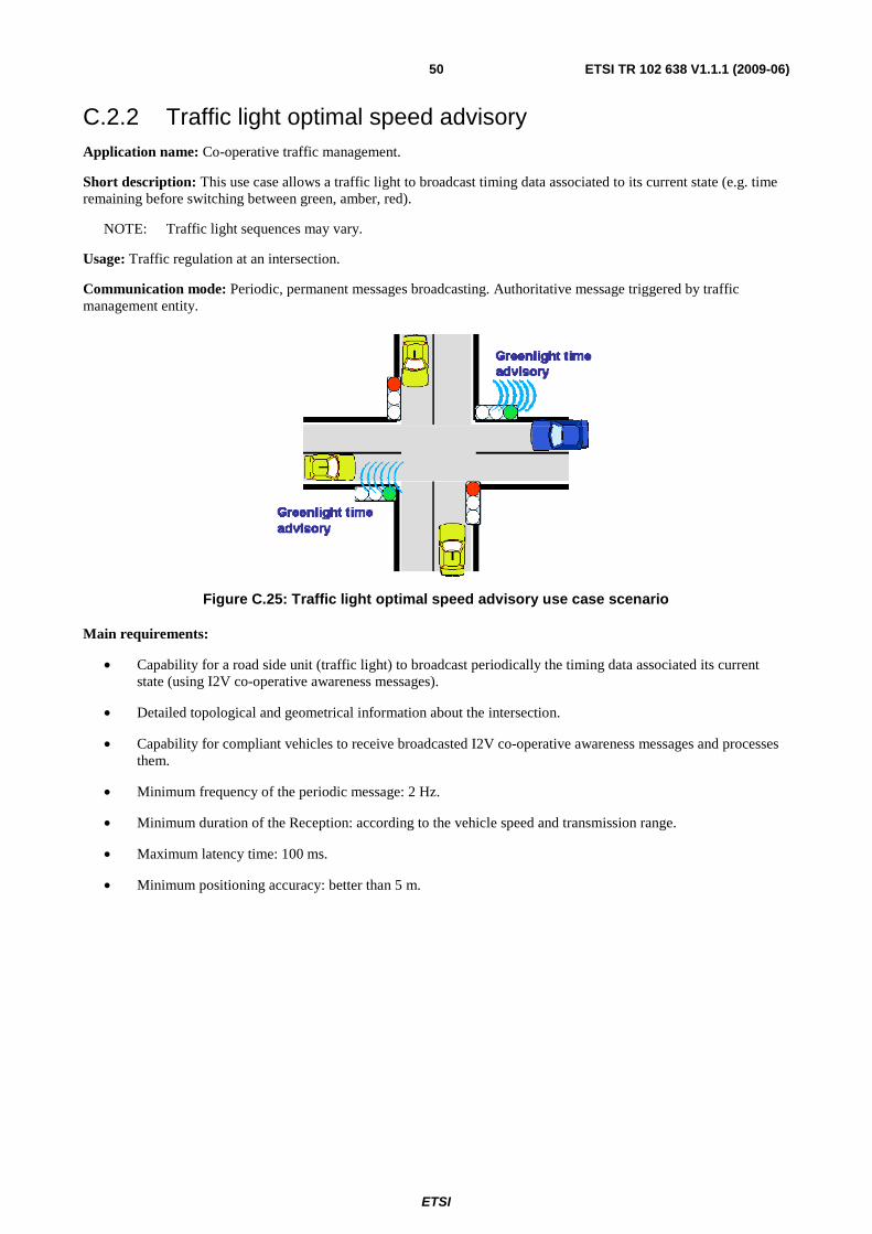
ETSI
ETSI TR 102 638 V1.1.1 (2009-06) 50
C.2.2 Traffic light optimal speed advisory Application name: Co-operative traffic management.
Short description: This use case allows a traffic light to broadcast timing data associated to its current state (e.g. time remaining before switching between green, amber, red).
NOTE: Traffic light sequences may vary.
Usage: Traffic regulation at an intersection.
Communication mode: Periodic, permanent messages broadcasting. Authoritative message triggered by traffic management entity.
Figure C.25: Traffic light optimal speed advisory use case scenario
Main requirements:
• Capability for a road side unit (traffic light) to broadcast periodically the timing data associated its current state (using I2V co-operative awareness messages).
• Detailed topological and geometrical information about the intersection.
• Capability for compliant vehicles to receive broadcasted I2V co-operative awareness messages and processes them.
• Minimum frequency of the periodic message: 2 Hz.
• Minimum duration of the Reception: according to the vehicle speed and transmission range.
• Maximum latency time: 100 ms.
• Minimum positioning accuracy: better than 5 m.
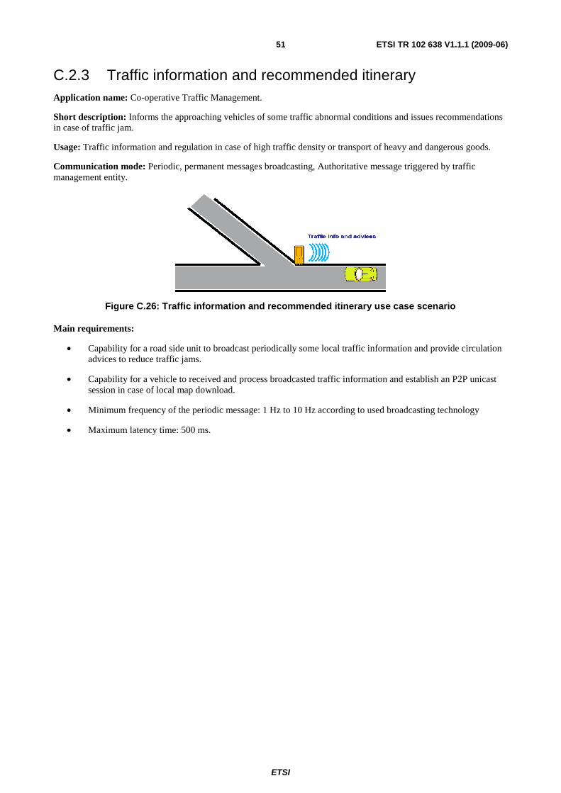
ETSI
ETSI TR 102 638 V1.1.1 (2009-06) 51
C.2.3 Traffic information and recommended itinerary Application name: Co-operative Traffic Management.
Short description: Informs the approaching vehicles of some traffic abnormal conditions and issues recommendations in case of traffic jam.
Usage: Traffic information and regulation in case of high traffic density or transport of heavy and dangerous goods.
Communication mode: Periodic, permanent messages broadcasting, Authoritative message triggered by traffic management entity.
Figure C.26: Traffic information and recommended itinerary use case scenario
Main requirements:
• Capability for a road side unit to broadcast periodically some local traffic information and provide circulation advices to reduce traffic jams.
• Capability for a vehicle to received and process broadcasted traffic information and establish an P2P unicast session in case of local map download.
• Minimum frequency of the periodic message: 1 Hz to 10 Hz according to used broadcasting technology
• Maximum latency time: 500 ms.
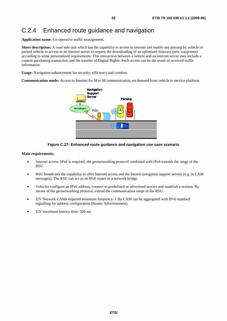
ETSI
ETSI TR 102 638 V1.1.1 (2009-06) 52
C.2.4 Enhanced route guidance and navigation Application name: Co-operative traffic management.
Short description: A road side unit which has the capability to access to internet and enable any passing by vehicle or parked vehicle to access to an internet server to request the downloading of an optimized itinerary (new waypoints) according to some personalized requirements. This interaction between a vehicle and an internet server may include a content purchasing transaction and the transfer of Digital Rights. Such access can be the result of received traffic information.
Usage: Navigation enhancement for security, efficiency and comfort.
Communication mode: Access to Internet for M to M communication, on demand from vehicle to service platform.
Figure C.27: Enhanced route guidance and navigation use case scenario
Main requirements:
• Internet access: IPv6 is required, the geonetworking protocol combined with IPv6 extends the range of the RSU.
• RSU broadcasts the capability to offer Internet access and the known navigation support servers (e.g. in CAM messages). The RSU can act as an IPv6 router or a network bridge.
• Vehicles configure an IPv6 address, connect to predefined or advertised servers and establish a session. By means of the geonetworking protocol, extend the communication range of the RSU.
• I2V Network CAMs required minimum frequency: 1 Hz CAM can be aggregated with IPv6 standard signalling for address configuration (Router Advertisement).
• I2V maximum latency time: 500 ms.
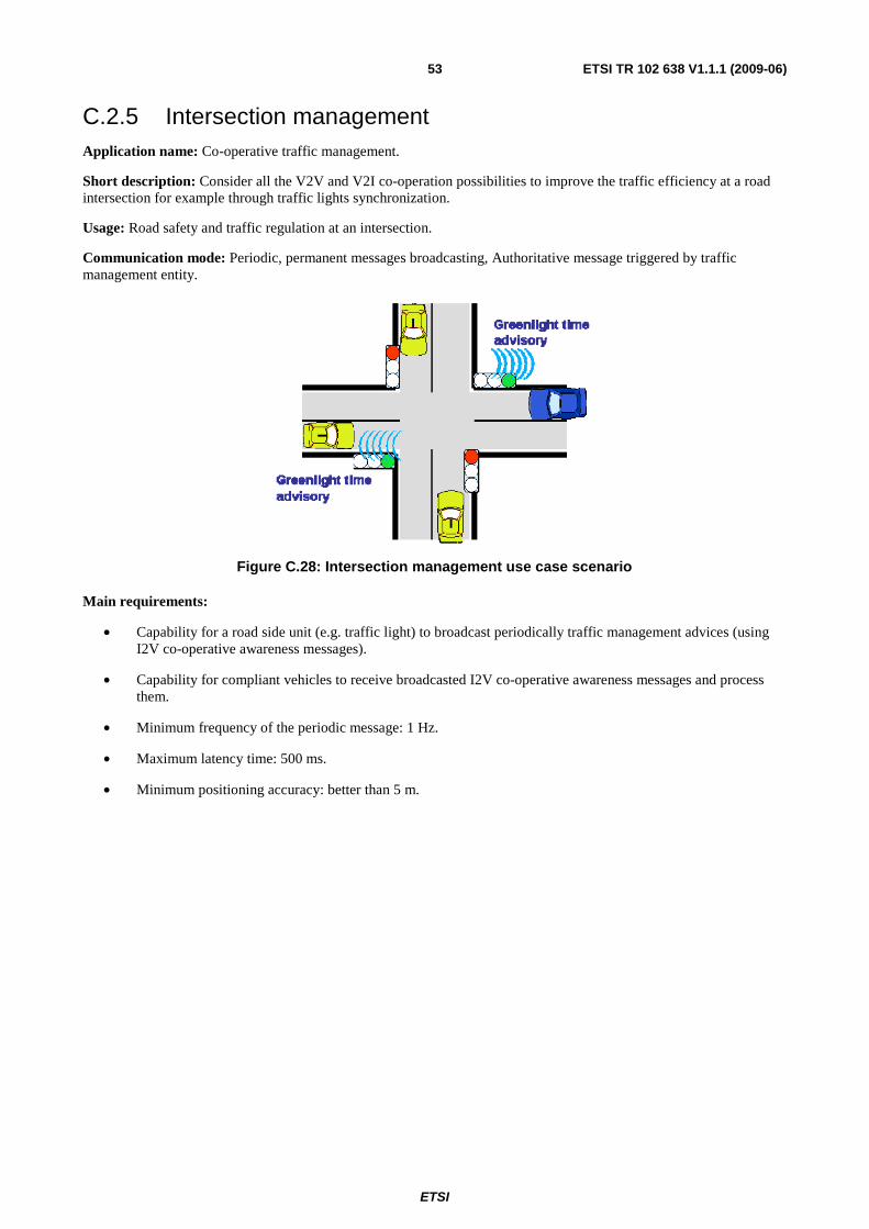
ETSI
ETSI TR 102 638 V1.1.1 (2009-06) 53
C.2.5 Intersection management Application name: Co-operative traffic management.
Short description: Consider all the V2V and V2I co-operation possibilities to improve the traffic efficiency at a road intersection for example through traffic lights synchronization.
Usage: Road safety and traffic regulation at an intersection.
Communication mode: Periodic, permanent messages broadcasting, Authoritative message triggered by traffic management entity.
Figure C.28: Intersection management use case scenario
Main requirements:
• Capability for a road side unit (e.g. traffic light) to broadcast periodically traffic management advices (using I2V co-operative awareness messages).
• Capability for compliant vehicles to receive broadcasted I2V co-operative awareness messages and process them.
• Minimum frequency of the periodic message: 1 Hz.
• Maximum latency time: 500 ms.
• Minimum positioning accuracy: better than 5 m.
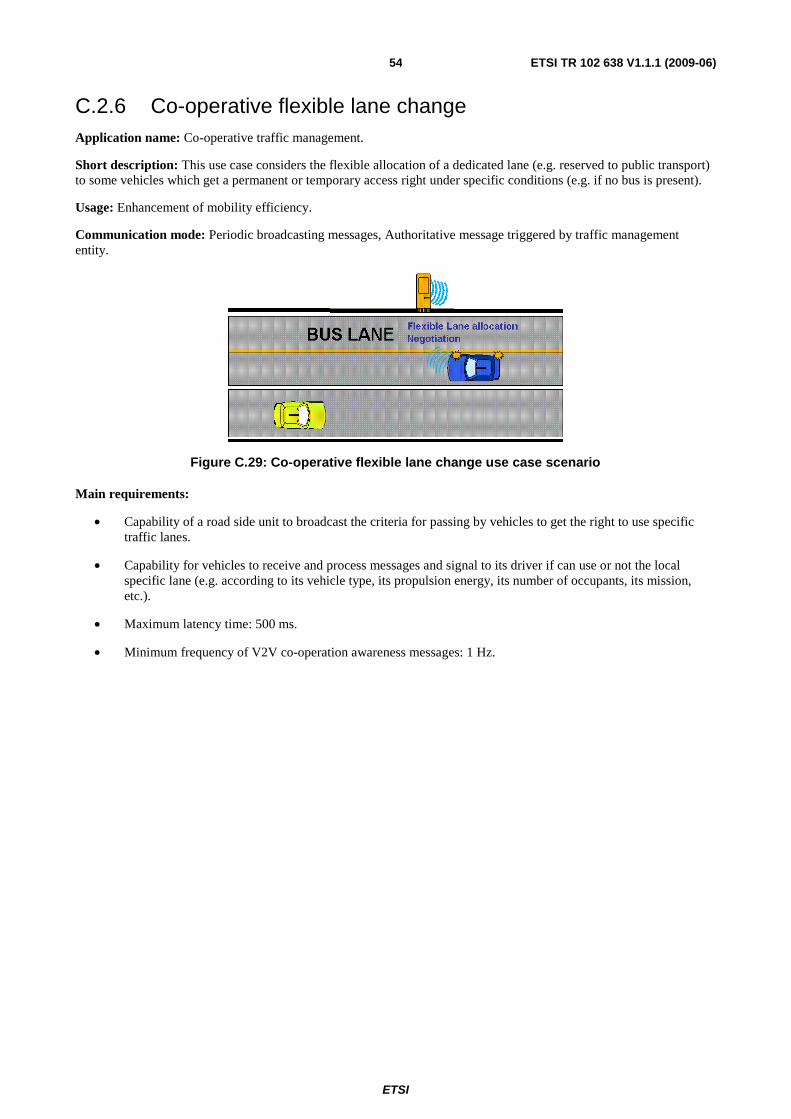
ETSI
ETSI TR 102 638 V1.1.1 (2009-06) 54
C.2.6 Co-operative flexible lane change Application name: Co-operative traffic management.
Short description: This use case considers the flexible allocation of a dedicated lane (e.g. reserved to public transport) to some vehicles which get a permanent or temporary access right under specific conditions (e.g. if no bus is present).
Usage: Enhancement of mobility efficiency.
Communication mode: Periodic broadcasting messages, Authoritative message triggered by traffic management entity.
Figure C.29: Co-operative flexible lane change use case scenario
Main requirements:
• Capability of a road side unit to broadcast the criteria for passing by vehicles to get the right to use specific traffic lanes.
• Capability for vehicles to receive and process messages and signal to its driver if can use or not the local specific lane (e.g. according to its vehicle type, its propulsion energy, its number of occupants, its mission, etc.).
• Maximum latency time: 500 ms.
• Minimum frequency of V2V co-operation awareness messages: 1 Hz.
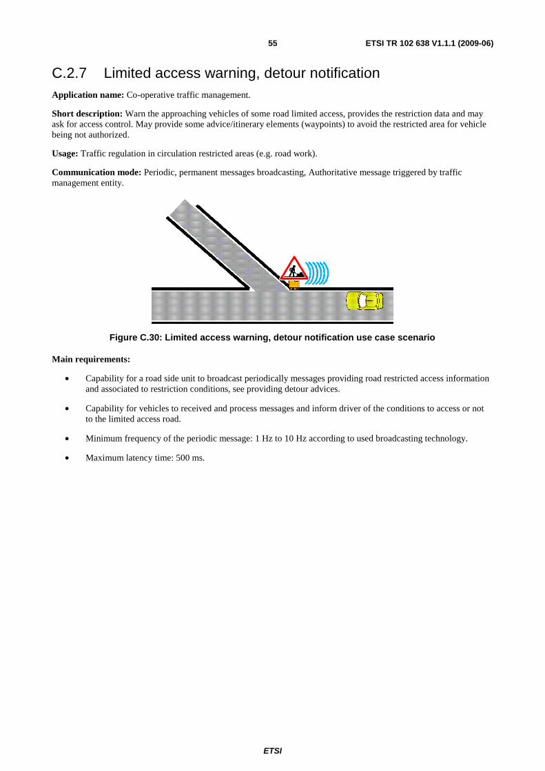
ETSI
ETSI TR 102 638 V1.1.1 (2009-06) 55
C.2.7 Limited access warning, detour notification Application name: Co-operative traffic management.
Short description: Warn the approaching vehicles of some road limited access, provides the restriction data and may ask for access control. May provide some advice/itinerary elements (waypoints) to avoid the restricted area for vehicle being not authorized.
Usage: Traffic regulation in circulation restricted areas (e.g. road work).
Communication mode: Periodic, permanent messages broadcasting, Authoritative message triggered by traffic management entity.
Figure C.30: Limited access warning, detour notification use case scenario
Main requirements:
• Capability for a road side unit to broadcast periodically messages providing road restricted access information and associated to restriction conditions, see providing detour advices.
• Capability for vehicles to received and process messages and inform driver of the conditions to access or not to the limited access road.
• Minimum frequency of the periodic message: 1 Hz to 10 Hz according to used broadcasting technology.
• Maximum latency time: 500 ms.
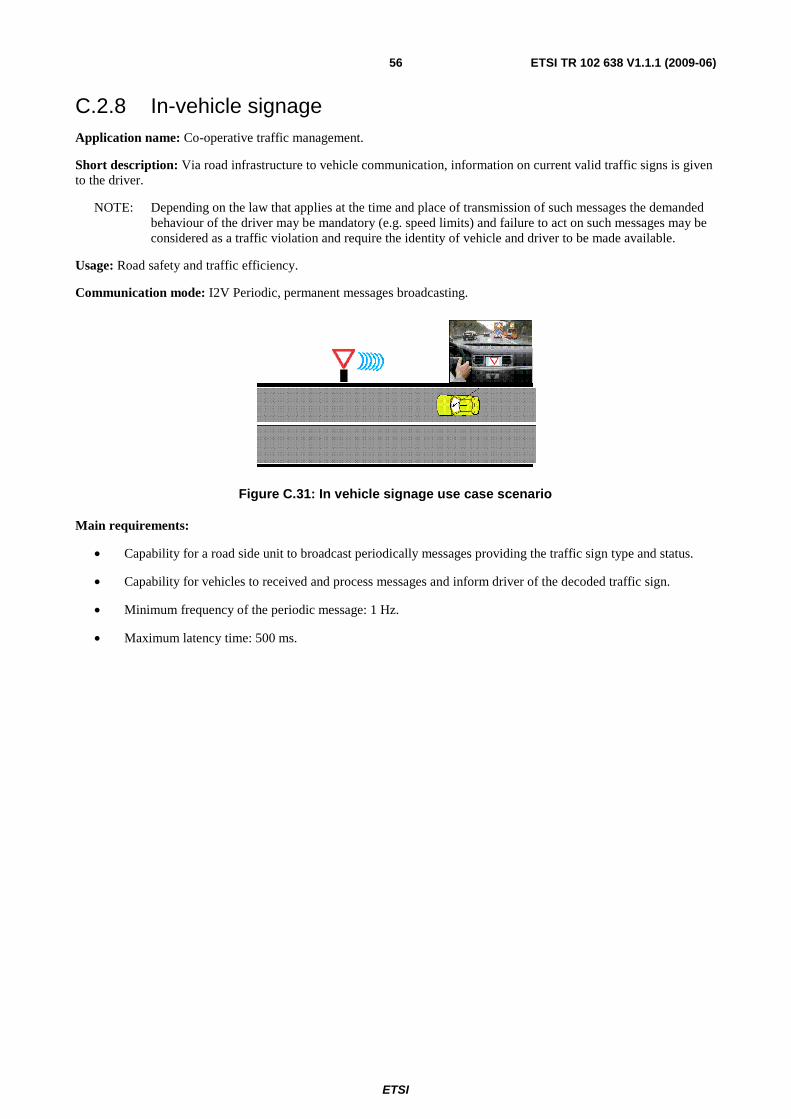
ETSI
ETSI TR 102 638 V1.1.1 (2009-06) 56
C.2.8 In-vehicle signage Application name: Co-operative traffic management.
Short description: Via road infrastructure to vehicle communication, information on current valid traffic signs is given to the driver.
NOTE: Depending on the law that applies at the time and place of transmission of such messages the demanded behaviour of the driver may be mandatory (e.g. speed limits) and failure to act on such messages may be considered as a traffic violation and require the identity of vehicle and driver to be made available.
Usage: Road safety and traffic efficiency.
Communication mode: I2V Periodic, permanent messages broadcasting.
Figure C.31: In vehicle signage use case scenario
Main requirements:
• Capability for a road side unit to broadcast periodically messages providing the traffic sign type and status.
• Capability for vehicles to received and process messages and inform driver of the decoded traffic sign.
• Minimum frequency of the periodic message: 1 Hz.
• Maximum latency time: 500 ms.
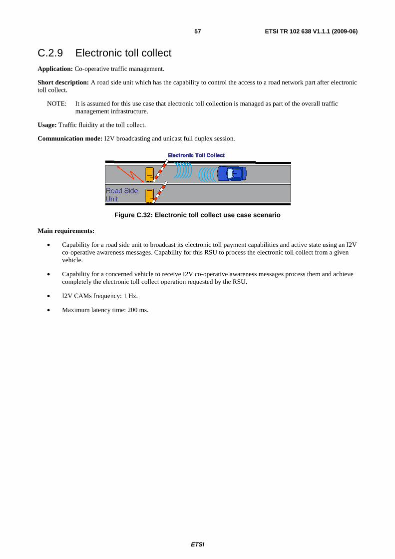
ETSI
ETSI TR 102 638 V1.1.1 (2009-06) 57
C.2.9 Electronic toll collect Application: Co-operative traffic management.
Short description: A road side unit which has the capability to control the access to a road network part after electronic toll collect.
NOTE: It is assumed for this use case that electronic toll collection is managed as part of the overall traffic management infrastructure.
Usage: Traffic fluidity at the toll collect.
Communication mode: I2V broadcasting and unicast full duplex session.
Figure C.32: Electronic toll collect use case scenario
Main requirements:
• Capability for a road side unit to broadcast its electronic toll payment capabilities and active state using an I2V co-operative awareness messages. Capability for this RSU to process the electronic toll collect from a given vehicle.
• Capability for a concerned vehicle to receive I2V co-operative awareness messages process them and achieve completely the electronic toll collect operation requested by the RSU.
• I2V CAMs frequency: 1 Hz.
• Maximum latency time: 200 ms.
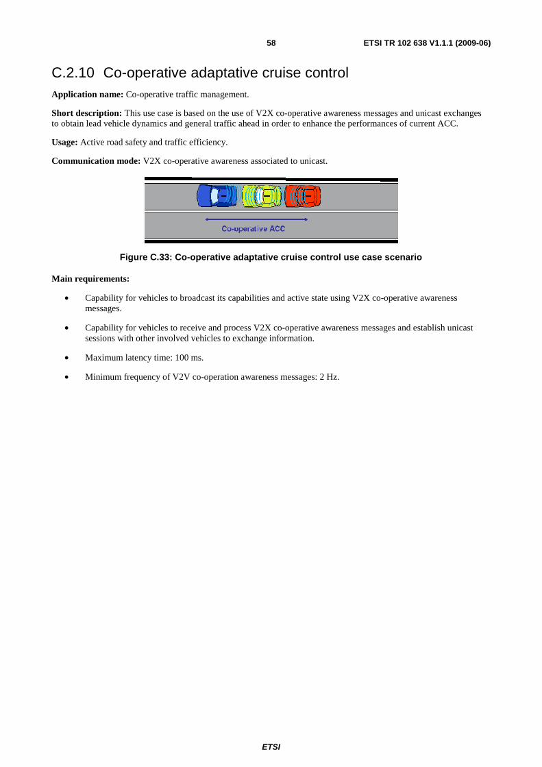
ETSI
ETSI TR 102 638 V1.1.1 (2009-06) 58
C.2.10 Co-operative adaptative cruise control Application name: Co-operative traffic management.
Short description: This use case is based on the use of V2X co-operative awareness messages and unicast exchanges to obtain lead vehicle dynamics and general traffic ahead in order to enhance the performances of current ACC.
Usage: Active road safety and traffic efficiency.
Communication mode: V2X co-operative awareness associated to unicast.
Figure C.33: Co-operative adaptative cruise control use case scenario
Main requirements:
• Capability for vehicles to broadcast its capabilities and active state using V2X co-operative awareness messages.
• Capability for vehicles to receive and process V2X co-operative awareness messages and establish unicast sessions with other involved vehicles to exchange information.
• Maximum latency time: 100 ms.
• Minimum frequency of V2V co-operation awareness messages: 2 Hz.
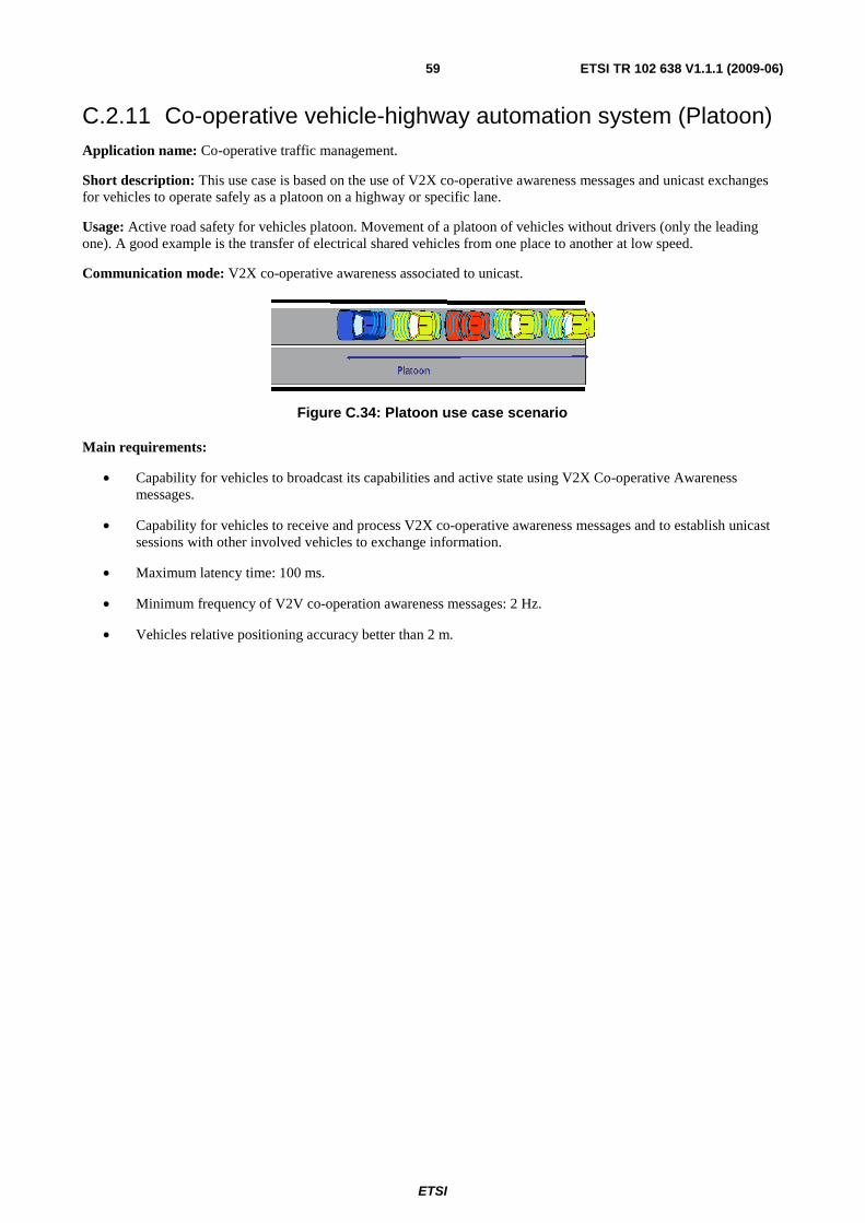
ETSI
ETSI TR 102 638 V1.1.1 (2009-06) 59
C.2.11 Co-operative vehicle-highway automation system (Platoon) Application name: Co-operative traffic management.
Short description: This use case is based on the use of V2X co-operative awareness messages and unicast exchanges for vehicles to operate safely as a platoon on a highway or specific lane.
Usage: Active road safety for vehicles platoon. Movement of a platoon of vehicles without drivers (only the leading one). A good example is the transfer of electrical shared vehicles from one place to another at low speed.
Communication mode: V2X co-operative awareness associated to unicast.
Figure C.34: Platoon use case scenario
Main requirements:
• Capability for vehicles to broadcast its capabilities and active state using V2X Co-operative Awareness messages.
• Capability for vehicles to receive and process V2X co-operative awareness messages and to establish unicast sessions with other involved vehicles to exchange information.
• Maximum latency time: 100 ms.
• Minimum frequency of V2V co-operation awareness messages: 2 Hz.
• Vehicles relative positioning accuracy better than 2 m.
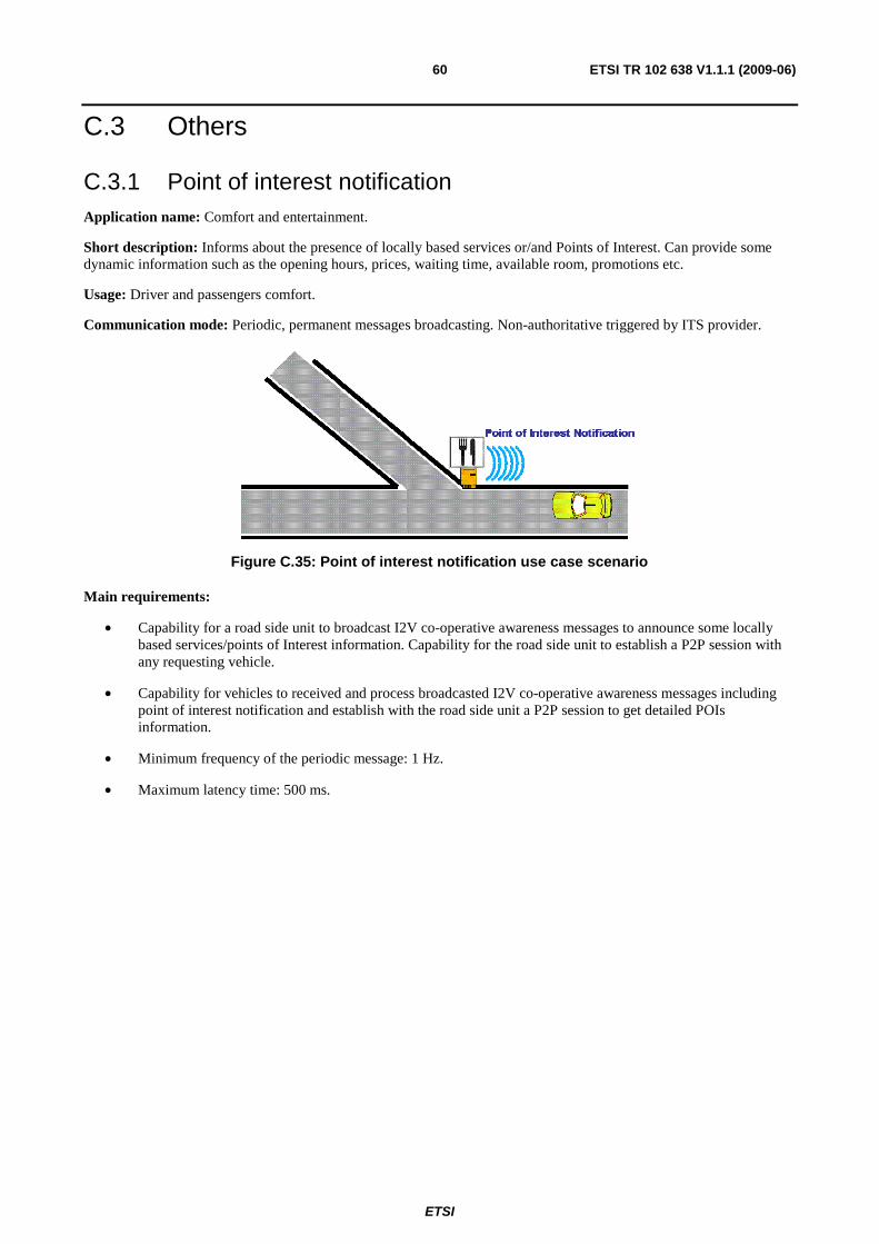
ETSI
ETSI TR 102 638 V1.1.1 (2009-06) 60
C.3 Others
C.3.1 Point of interest notification Application name: Comfort and entertainment.
Short description: Informs about the presence of locally based services or/and Points of Interest. Can provide some dynamic information such as the opening hours, prices, waiting time, available room, promotions etc.
Usage: Driver and passengers comfort.
Communication mode: Periodic, permanent messages broadcasting. Non-authoritative triggered by ITS provider.
Figure C.35: Point of interest notification use case scenario
Main requirements:
• Capability for a road side unit to broadcast I2V co-operative awareness messages to announce some locally based services/points of Interest information. Capability for the road side unit to establish a P2P session with any requesting vehicle.
• Capability for vehicles to received and process broadcasted I2V co-operative awareness messages including point of interest notification and establish with the road side unit a P2P session to get detailed POIs information.
• Minimum frequency of the periodic message: 1 Hz.
• Maximum latency time: 500 ms.
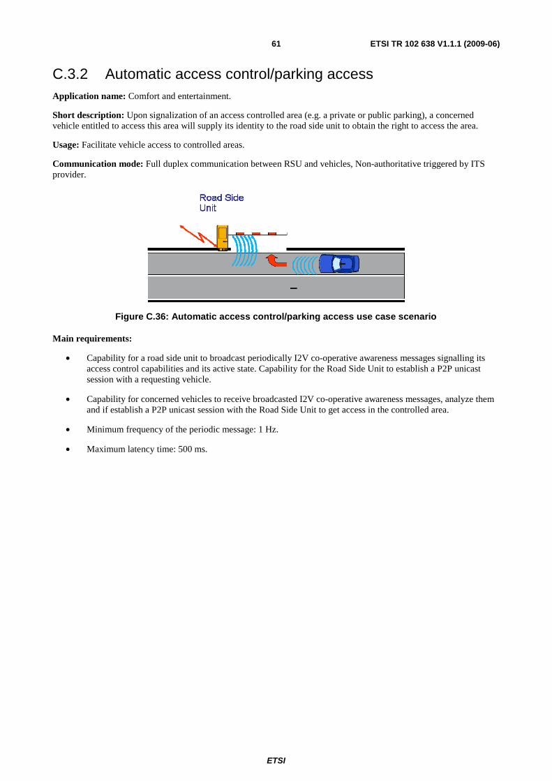
ETSI
ETSI TR 102 638 V1.1.1 (2009-06) 61
C.3.2 Automatic access control/parking access Application name: Comfort and entertainment.
Short description: Upon signalization of an access controlled area (e.g. a private or public parking), a concerned vehicle entitled to access this area will supply its identity to the road side unit to obtain the right to access the area.
Usage: Facilitate vehicle access to controlled areas.
Communication mode: Full duplex communication between RSU and vehicles, Non-authoritative triggered by ITS provider.
Figure C.36: Automatic access control/parking access use case scenario
Main requirements:
• Capability for a road side unit to broadcast periodically I2V co-operative awareness messages signalling its access control capabilities and its active state. Capability for the Road Side Unit to establish a P2P unicast session with a requesting vehicle.
• Capability for concerned vehicles to receive broadcasted I2V co-operative awareness messages, analyze them and if establish a P2P unicast session with the Road Side Unit to get access in the controlled area.
• Minimum frequency of the periodic message: 1 Hz.
• Maximum latency time: 500 ms.
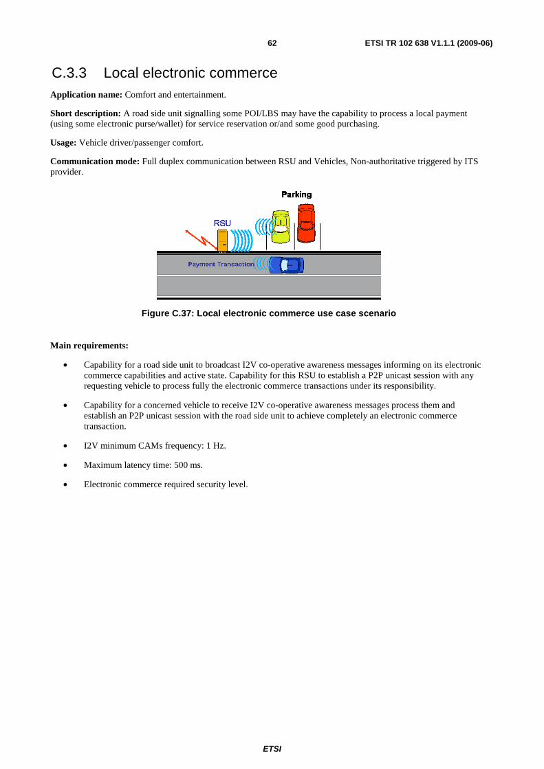
ETSI
ETSI TR 102 638 V1.1.1 (2009-06) 62
C.3.3 Local electronic commerce Application name: Comfort and entertainment.
Short description: A road side unit signalling some POI/LBS may have the capability to process a local payment (using some electronic purse/wallet) for service reservation or/and some good purchasing.
Usage: Vehicle driver/passenger comfort.
Communication mode: Full duplex communication between RSU and Vehicles, Non-authoritative triggered by ITS provider.
Figure C.37: Local electronic commerce use case scenario
Main requirements:
• Capability for a road side unit to broadcast I2V co-operative awareness messages informing on its electronic commerce capabilities and active state. Capability for this RSU to establish a P2P unicast session with any requesting vehicle to process fully the electronic commerce transactions under its responsibility.
• Capability for a concerned vehicle to receive I2V co-operative awareness messages process them and establish an P2P unicast session with the road side unit to achieve completely an electronic commerce transaction.
• I2V minimum CAMs frequency: 1 Hz.
• Maximum latency time: 500 ms.
• Electronic commerce required security level.
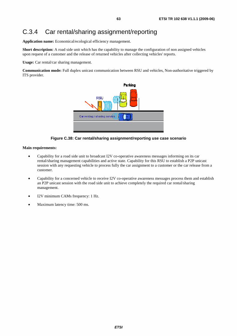
ETSI
ETSI TR 102 638 V1.1.1 (2009-06) 63
C.3.4 Car rental/sharing assignment/reporting Application name: Economical/ecological efficiency management.
Short description: A road side unit which has the capability to manage the configuration of non assigned vehicles upon request of a customer and the release of returned vehicles after collecting vehicles' reports.
Usage: Car rental/car sharing management.
Communication mode: Full duplex unicast communication between RSU and vehicles, Non-authoritative triggered by ITS provider.
Figure C.38: Car rental/sharing assignment/reporting use case scenario
Main requirements:
• Capability for a road side unit to broadcast I2V co-operative awareness messages informing on its car rental/sharing management capabilities and active state. Capability for this RSU to establish a P2P unicast session with any requesting vehicle to process fully the car assignment to a customer or the car release from a customer.
• Capability for a concerned vehicle to receive I2V co-operative awareness messages process them and establish an P2P unicast session with the road side unit to achieve completely the required car rental/sharing management.
• I2V minimum CAMs frequency: 1 Hz.
• Maximum latency time: 500 ms.
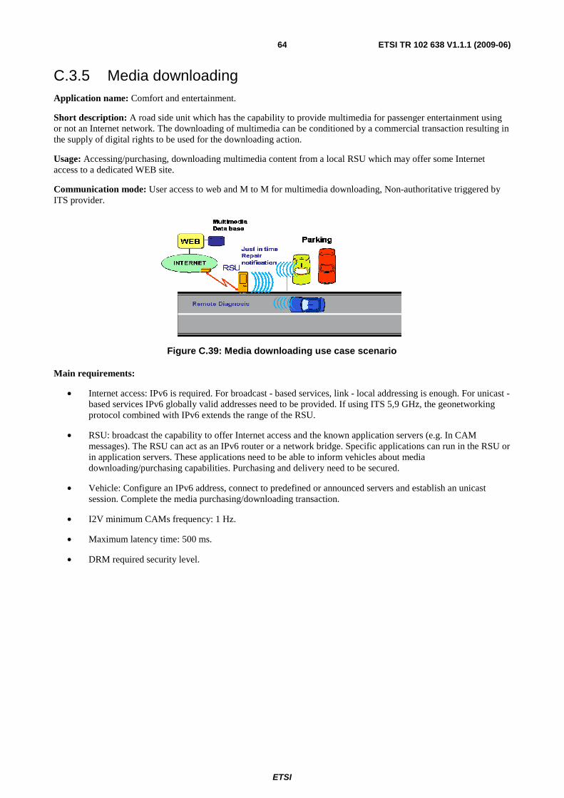
ETSI
ETSI TR 102 638 V1.1.1 (2009-06) 64
C.3.5 Media downloading Application name: Comfort and entertainment.
Short description: A road side unit which has the capability to provide multimedia for passenger entertainment using or not an Internet network. The downloading of multimedia can be conditioned by a commercial transaction resulting in the supply of digital rights to be used for the downloading action.
Usage: Accessing/purchasing, downloading multimedia content from a local RSU which may offer some Internet access to a dedicated WEB site.
Communication mode: User access to web and M to M for multimedia downloading, Non-authoritative triggered by ITS provider.
Figure C.39: Media downloading use case scenario
Main requirements:
• Internet access: IPv6 is required. For broadcast - based services, link - local addressing is enough. For unicast - based services IPv6 globally valid addresses need to be provided. If using ITS 5,9 GHz, the geonetworking protocol combined with IPv6 extends the range of the RSU.
• RSU: broadcast the capability to offer Internet access and the known application servers (e.g. In CAM messages). The RSU can act as an IPv6 router or a network bridge. Specific applications can run in the RSU or in application servers. These applications need to be able to inform vehicles about media downloading/purchasing capabilities. Purchasing and delivery need to be secured.
• Vehicle: Configure an IPv6 address, connect to predefined or announced servers and establish an unicast session. Complete the media purchasing/downloading transaction.
• I2V minimum CAMs frequency: 1 Hz.
• Maximum latency time: 500 ms.
• DRM required security level.
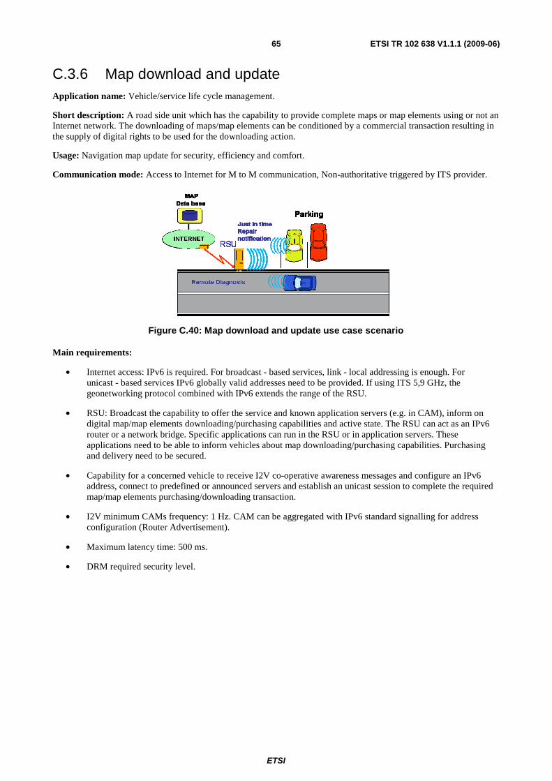
ETSI
ETSI TR 102 638 V1.1.1 (2009-06) 65
C.3.6 Map download and update Application name: Vehicle/service life cycle management.
Short description: A road side unit which has the capability to provide complete maps or map elements using or not an Internet network. The downloading of maps/map elements can be conditioned by a commercial transaction resulting in the supply of digital rights to be used for the downloading action.
Usage: Navigation map update for security, efficiency and comfort.
Communication mode: Access to Internet for M to M communication, Non-authoritative triggered by ITS provider.
Figure C.40: Map download and update use case scenario
Main requirements:
• Internet access: IPv6 is required. For broadcast - based services, link - local addressing is enough. For unicast - based services IPv6 globally valid addresses need to be provided. If using ITS 5,9 GHz, the geonetworking protocol combined with IPv6 extends the range of the RSU.
• RSU: Broadcast the capability to offer the service and known application servers (e.g. in CAM), inform on digital map/map elements downloading/purchasing capabilities and active state. The RSU can act as an IPv6 router or a network bridge. Specific applications can run in the RSU or in application servers. These applications need to be able to inform vehicles about map downloading/purchasing capabilities. Purchasing and delivery need to be secured.
• Capability for a concerned vehicle to receive I2V co-operative awareness messages and configure an IPv6 address, connect to predefined or announced servers and establish an unicast session to complete the required map/map elements purchasing/downloading transaction.
• I2V minimum CAMs frequency: 1 Hz. CAM can be aggregated with IPv6 standard signalling for address configuration (Router Advertisement).
• Maximum latency time: 500 ms.
• DRM required security level.
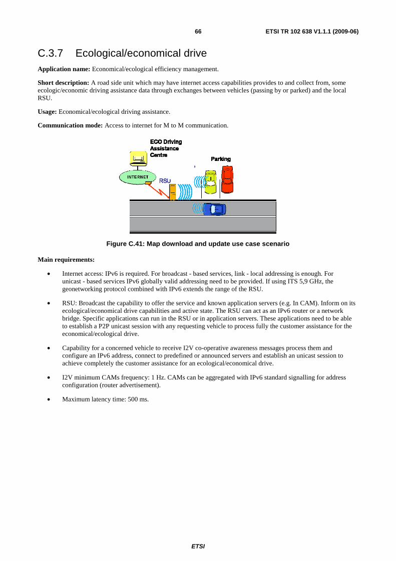
ETSI
ETSI TR 102 638 V1.1.1 (2009-06) 66
C.3.7 Ecological/economical drive Application name: Economical/ecological efficiency management.
Short description: A road side unit which may have internet access capabilities provides to and collect from, some ecologic/economic driving assistance data through exchanges between vehicles (passing by or parked) and the local RSU.
Usage: Economical/ecological driving assistance.
Communication mode: Access to internet for M to M communication.
Figure C.41: Map download and update use case scenario
Main requirements:
• Internet access: IPv6 is required. For broadcast - based services, link - local addressing is enough. For unicast - based services IPv6 globally valid addressing need to be provided. If using ITS 5,9 GHz, the geonetworking protocol combined with IPv6 extends the range of the RSU.
• RSU: Broadcast the capability to offer the service and known application servers (e.g. In CAM). Inform on its ecological/economical drive capabilities and active state. The RSU can act as an IPv6 router or a network bridge. Specific applications can run in the RSU or in application servers. These applications need to be able to establish a P2P unicast session with any requesting vehicle to process fully the customer assistance for the economical/ecological drive.
• Capability for a concerned vehicle to receive I2V co-operative awareness messages process them and configure an IPv6 address, connect to predefined or announced servers and establish an unicast session to achieve completely the customer assistance for an ecological/economical drive.
• I2V minimum CAMs frequency: 1 Hz. CAMs can be aggregated with IPv6 standard signalling for address configuration (router advertisement).
• Maximum latency time: 500 ms.
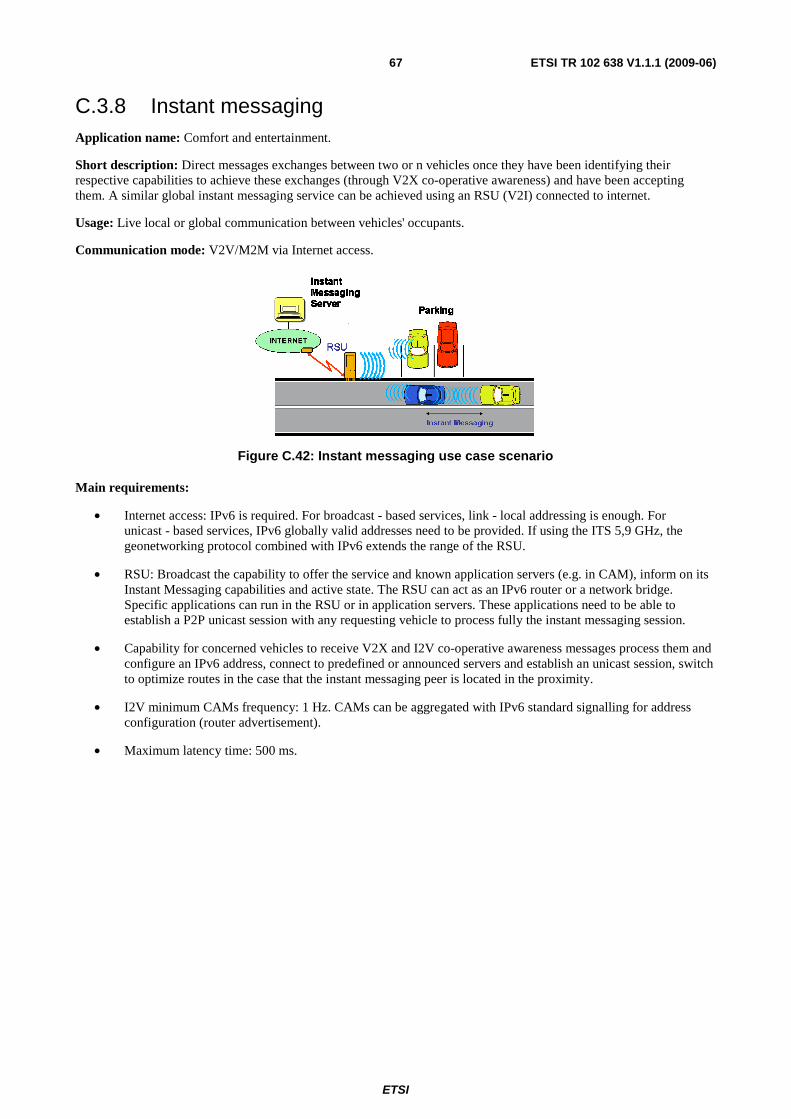
ETSI
ETSI TR 102 638 V1.1.1 (2009-06) 67
C.3.8 Instant messaging Application name: Comfort and entertainment.
Short description: Direct messages exchanges between two or n vehicles once they have been identifying their respective capabilities to achieve these exchanges (through V2X co-operative awareness) and have been accepting them. A similar global instant messaging service can be achieved using an RSU (V2I) connected to internet.
Usage: Live local or global communication between vehicles' occupants.
Communication mode: V2V/M2M via Internet access.
Figure C.42: Instant messaging use case scenario
Main requirements:
• Internet access: IPv6 is required. For broadcast - based services, link - local addressing is enough. For unicast - based services, IPv6 globally valid addresses need to be provided. If using the ITS 5,9 GHz, the geonetworking protocol combined with IPv6 extends the range of the RSU.
• RSU: Broadcast the capability to offer the service and known application servers (e.g. in CAM), inform on its Instant Messaging capabilities and active state. The RSU can act as an IPv6 router or a network bridge. Specific applications can run in the RSU or in application servers. These applications need to be able to establish a P2P unicast session with any requesting vehicle to process fully the instant messaging session.
• Capability for concerned vehicles to receive V2X and I2V co-operative awareness messages process them and configure an IPv6 address, connect to predefined or announced servers and establish an unicast session, switch to optimize routes in the case that the instant messaging peer is located in the proximity.
• I2V minimum CAMs frequency: 1 Hz. CAMs can be aggregated with IPv6 standard signalling for address configuration (router advertisement).
• Maximum latency time: 500 ms.
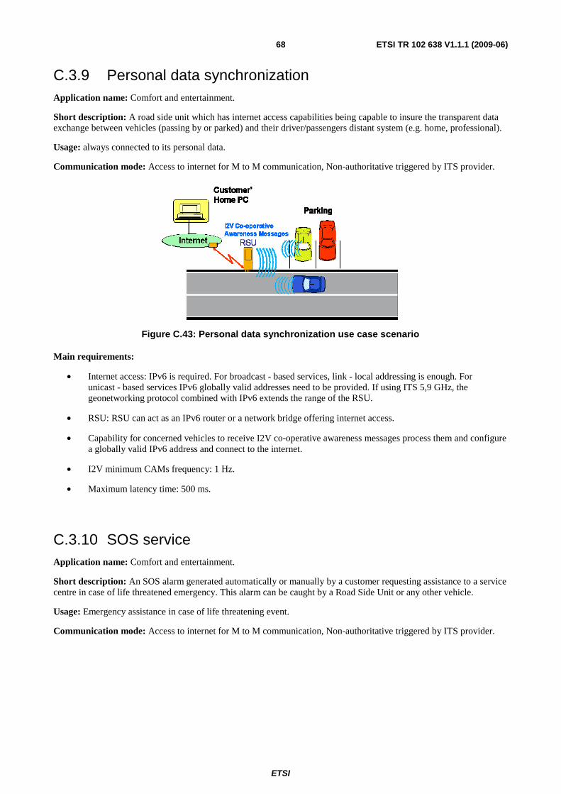
ETSI
ETSI TR 102 638 V1.1.1 (2009-06) 68
C.3.9 Personal data synchronization Application name: Comfort and entertainment.
Short description: A road side unit which has internet access capabilities being capable to insure the transparent data exchange between vehicles (passing by or parked) and their driver/passengers distant system (e.g. home, professional).
Usage: always connected to its personal data.
Communication mode: Access to internet for M to M communication, Non-authoritative triggered by ITS provider.
Figure C.43: Personal data synchronization use case scenario
Main requirements:
• Internet access: IPv6 is required. For broadcast - based services, link - local addressing is enough. For unicast - based services IPv6 globally valid addresses need to be provided. If using ITS 5,9 GHz, the geonetworking protocol combined with IPv6 extends the range of the RSU.
• RSU: RSU can act as an IPv6 router or a network bridge offering internet access.
• Capability for concerned vehicles to receive I2V co-operative awareness messages process them and configure a globally valid IPv6 address and connect to the internet.
• I2V minimum CAMs frequency: 1 Hz.
• Maximum latency time: 500 ms.
C.3.10 SOS service Application name: Comfort and entertainment.
Short description: An SOS alarm generated automatically or manually by a customer requesting assistance to a service centre in case of life threatened emergency. This alarm can be caught by a Road Side Unit or any other vehicle.
Usage: Emergency assistance in case of life threatening event.
Communication mode: Access to internet for M to M communication, Non-authoritative triggered by ITS provider.
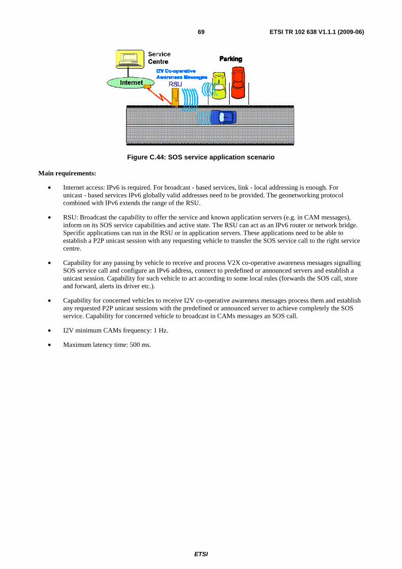
ETSI
ETSI TR 102 638 V1.1.1 (2009-06) 69
Figure C.44: SOS service application scenario
Main requirements:
• Internet access: IPv6 is required. For broadcast - based services, link - local addressing is enough. For unicast - based services IPv6 globally valid addresses need to be provided. The geonetworking protocol combined with IPv6 extends the range of the RSU.
• RSU: Broadcast the capability to offer the service and known application servers (e.g. in CAM messages), inform on its SOS service capabilities and active state. The RSU can act as an IPv6 router or network bridge. Specific applications can run in the RSU or in application servers. These applications need to be able to establish a P2P unicast session with any requesting vehicle to transfer the SOS service call to the right service centre.
• Capability for any passing by vehicle to receive and process V2X co-operative awareness messages signalling SOS service call and configure an IPv6 address, connect to predefined or announced servers and establish a unicast session. Capability for such vehicle to act according to some local rules (forwards the SOS call, store and forward, alerts its driver etc.).
• Capability for concerned vehicles to receive I2V co-operative awareness messages process them and establish any requested P2P unicast sessions with the predefined or announced server to achieve completely the SOS service. Capability for concerned vehicle to broadcast in CAMs messages an SOS call.
• I2V minimum CAMs frequency: 1 Hz.
• Maximum latency time: 500 ms.
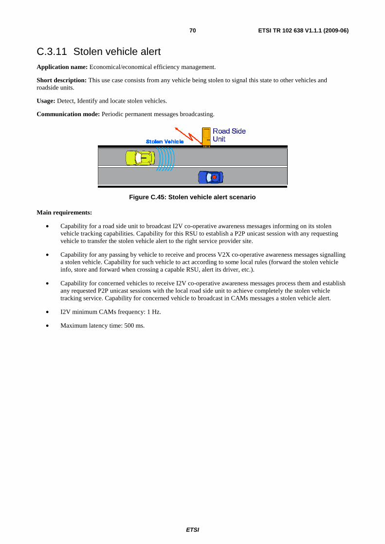
ETSI
ETSI TR 102 638 V1.1.1 (2009-06) 70
C.3.11 Stolen vehicle alert Application name: Economical/economical efficiency management.
Short description: This use case consists from any vehicle being stolen to signal this state to other vehicles and roadside units.
Usage: Detect, Identify and locate stolen vehicles.
Communication mode: Periodic permanent messages broadcasting.
Figure C.45: Stolen vehicle alert scenario
Main requirements:
• Capability for a road side unit to broadcast I2V co-operative awareness messages informing on its stolen vehicle tracking capabilities. Capability for this RSU to establish a P2P unicast session with any requesting vehicle to transfer the stolen vehicle alert to the right service provider site.
• Capability for any passing by vehicle to receive and process V2X co-operative awareness messages signalling a stolen vehicle. Capability for such vehicle to act according to some local rules (forward the stolen vehicle info, store and forward when crossing a capable RSU, alert its driver, etc.).
• Capability for concerned vehicles to receive I2V co-operative awareness messages process them and establish any requested P2P unicast sessions with the local road side unit to achieve completely the stolen vehicle tracking service. Capability for concerned vehicle to broadcast in CAMs messages a stolen vehicle alert.
• I2V minimum CAMs frequency: 1 Hz.
• Maximum latency time: 500 ms.
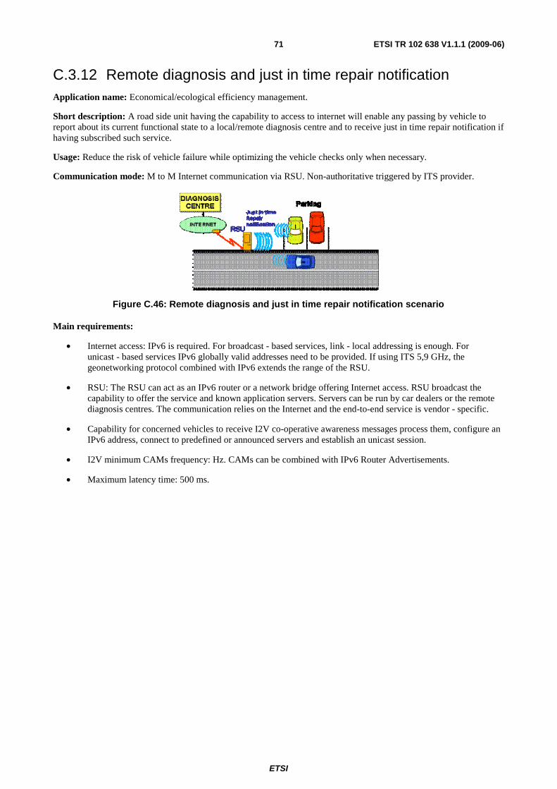
ETSI
ETSI TR 102 638 V1.1.1 (2009-06) 71
C.3.12 Remote diagnosis and just in time repair notification Application name: Economical/ecological efficiency management.
Short description: A road side unit having the capability to access to internet will enable any passing by vehicle to report about its current functional state to a local/remote diagnosis centre and to receive just in time repair notification if having subscribed such service.
Usage: Reduce the risk of vehicle failure while optimizing the vehicle checks only when necessary.
Communication mode: M to M Internet communication via RSU. Non-authoritative triggered by ITS provider.
Figure C.46: Remote diagnosis and just in time repair notification scenario
Main requirements:
• Internet access: IPv6 is required. For broadcast - based services, link - local addressing is enough. For unicast - based services IPv6 globally valid addresses need to be provided. If using ITS 5,9 GHz, the geonetworking protocol combined with IPv6 extends the range of the RSU.
• RSU: The RSU can act as an IPv6 router or a network bridge offering Internet access. RSU broadcast the capability to offer the service and known application servers. Servers can be run by car dealers or the remote diagnosis centres. The communication relies on the Internet and the end-to-end service is vendor - specific.
• Capability for concerned vehicles to receive I2V co-operative awareness messages process them, configure an IPv6 address, connect to predefined or announced servers and establish an unicast session.
• I2V minimum CAMs frequency: Hz. CAMs can be combined with IPv6 Router Advertisements.
• Maximum latency time: 500 ms.
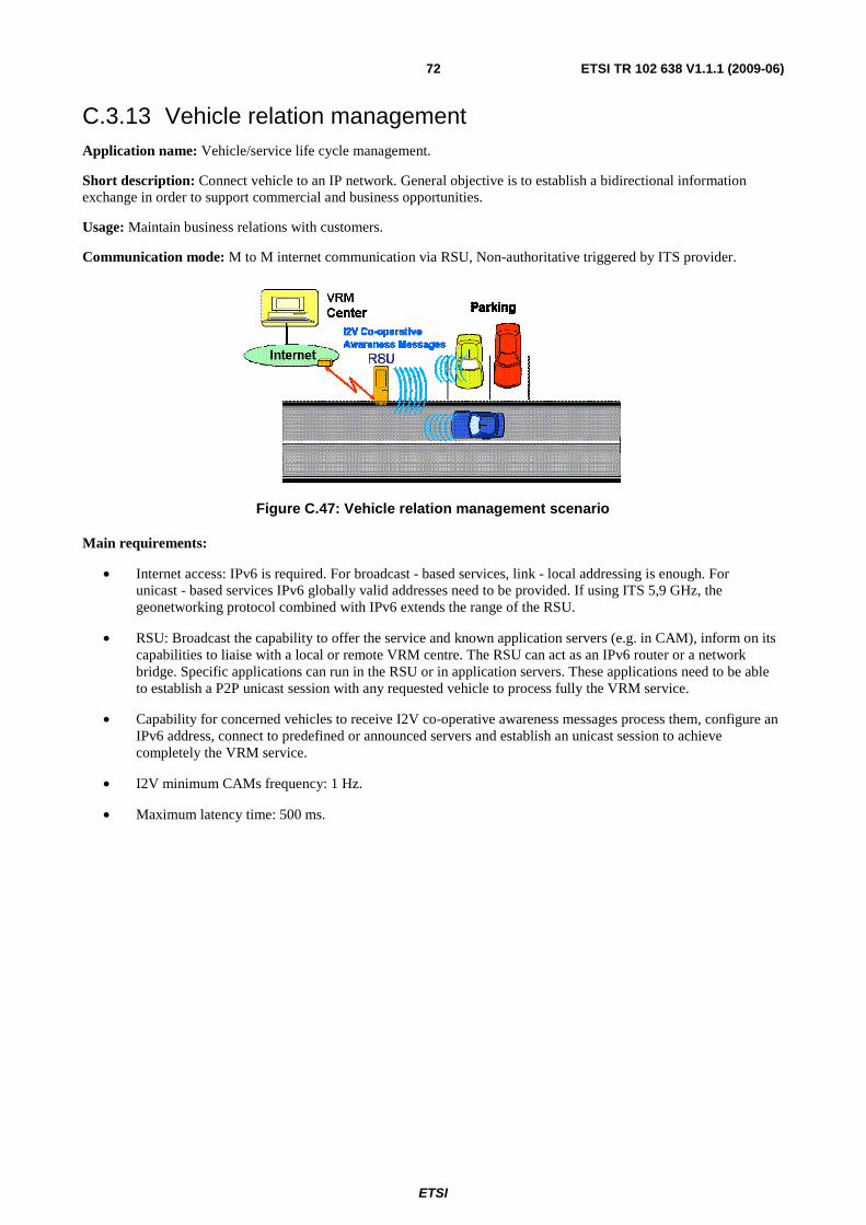
ETSI
ETSI TR 102 638 V1.1.1 (2009-06) 72
C.3.13 Vehicle relation management Application name: Vehicle/service life cycle management.
Short description: Connect vehicle to an IP network. General objective is to establish a bidirectional information exchange in order to support commercial and business opportunities.
Usage: Maintain business relations with customers.
Communication mode: M to M internet communication via RSU, Non-authoritative triggered by ITS provider.
Figure C.47: Vehicle relation management scenario
Main requirements:
• Internet access: IPv6 is required. For broadcast - based services, link - local addressing is enough. For unicast - based services IPv6 globally valid addresses need to be provided. If using ITS 5,9 GHz, the geonetworking protocol combined with IPv6 extends the range of the RSU.
• RSU: Broadcast the capability to offer the service and known application servers (e.g. in CAM), inform on its capabilities to liaise with a local or remote VRM centre. The RSU can act as an IPv6 router or a network bridge. Specific applications can run in the RSU or in application servers. These applications need to be able to establish a P2P unicast session with any requested vehicle to process fully the VRM service.
• Capability for concerned vehicles to receive I2V co-operative awareness messages process them, configure an IPv6 address, connect to predefined or announced servers and establish an unicast session to achieve completely the VRM service.
• I2V minimum CAMs frequency: 1 Hz.
• Maximum latency time: 500 ms.
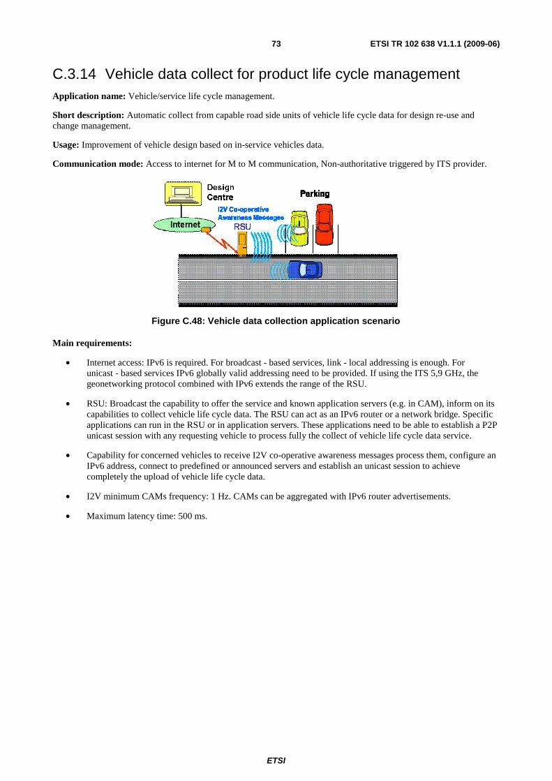
ETSI
ETSI TR 102 638 V1.1.1 (2009-06) 73
C.3.14 Vehicle data collect for product life cycle management Application name: Vehicle/service life cycle management.
Short description: Automatic collect from capable road side units of vehicle life cycle data for design re-use and change management.
Usage: Improvement of vehicle design based on in-service vehicles data.
Communication mode: Access to internet for M to M communication, Non-authoritative triggered by ITS provider.
Figure C.48: Vehicle data collection application scenario
Main requirements:
• Internet access: IPv6 is required. For broadcast - based services, link - local addressing is enough. For unicast - based services IPv6 globally valid addressing need to be provided. If using the ITS 5,9 GHz, the geonetworking protocol combined with IPv6 extends the range of the RSU.
• RSU: Broadcast the capability to offer the service and known application servers (e.g. in CAM), inform on its capabilities to collect vehicle life cycle data. The RSU can act as an IPv6 router or a network bridge. Specific applications can run in the RSU or in application servers. These applications need to be able to establish a P2P unicast session with any requesting vehicle to process fully the collect of vehicle life cycle data service.
• Capability for concerned vehicles to receive I2V co-operative awareness messages process them, configure an IPv6 address, connect to predefined or announced servers and establish an unicast session to achieve completely the upload of vehicle life cycle data.
• I2V minimum CAMs frequency: 1 Hz. CAMs can be aggregated with IPv6 router advertisements.
• Maximum latency time: 500 ms.
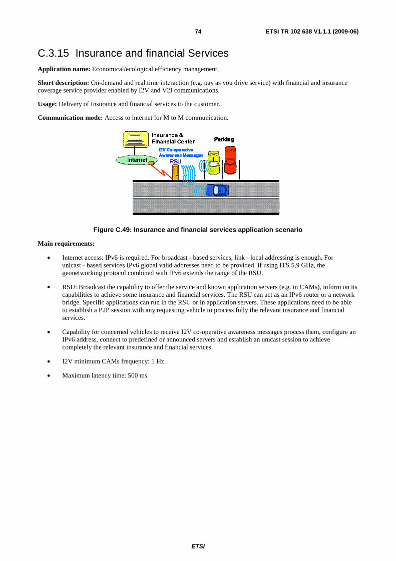
ETSI
ETSI TR 102 638 V1.1.1 (2009-06) 74
C.3.15 Insurance and financial Services Application name: Economical/ecological efficiency management.
Short description: On-demand and real time interaction (e.g. pay as you drive service) with financial and insurance coverage service provider enabled by I2V and V2I communications.
Usage: Delivery of Insurance and financial services to the customer.
Communication mode: Access to internet for M to M communication.
Figure C.49: Insurance and financial services application scenario
Main requirements:
• Internet access: IPv6 is required. For broadcast - based services, link - local addressing is enough. For unicast - based services IPv6 global valid addresses need to be provided. If using ITS 5,9 GHz, the geonetworking protocol combined with IPv6 extends the range of the RSU.
• RSU: Broadcast the capability to offer the service and known application servers (e.g. in CAMs), inform on its capabilities to achieve some insurance and financial services. The RSU can act as an IPv6 router or a network bridge. Specific applications can run in the RSU or in application servers. These applications need to be able to establish a P2P session with any requesting vehicle to process fully the relevant insurance and financial services.
• Capability for concerned vehicles to receive I2V co-operative awareness messages process them, configure an IPv6 address, connect to predefined or announced servers and establish an unicast session to achieve completely the relevant insurance and financial services.
• I2V minimum CAMs frequency: 1 Hz.
• Maximum latency time: 500 ms.
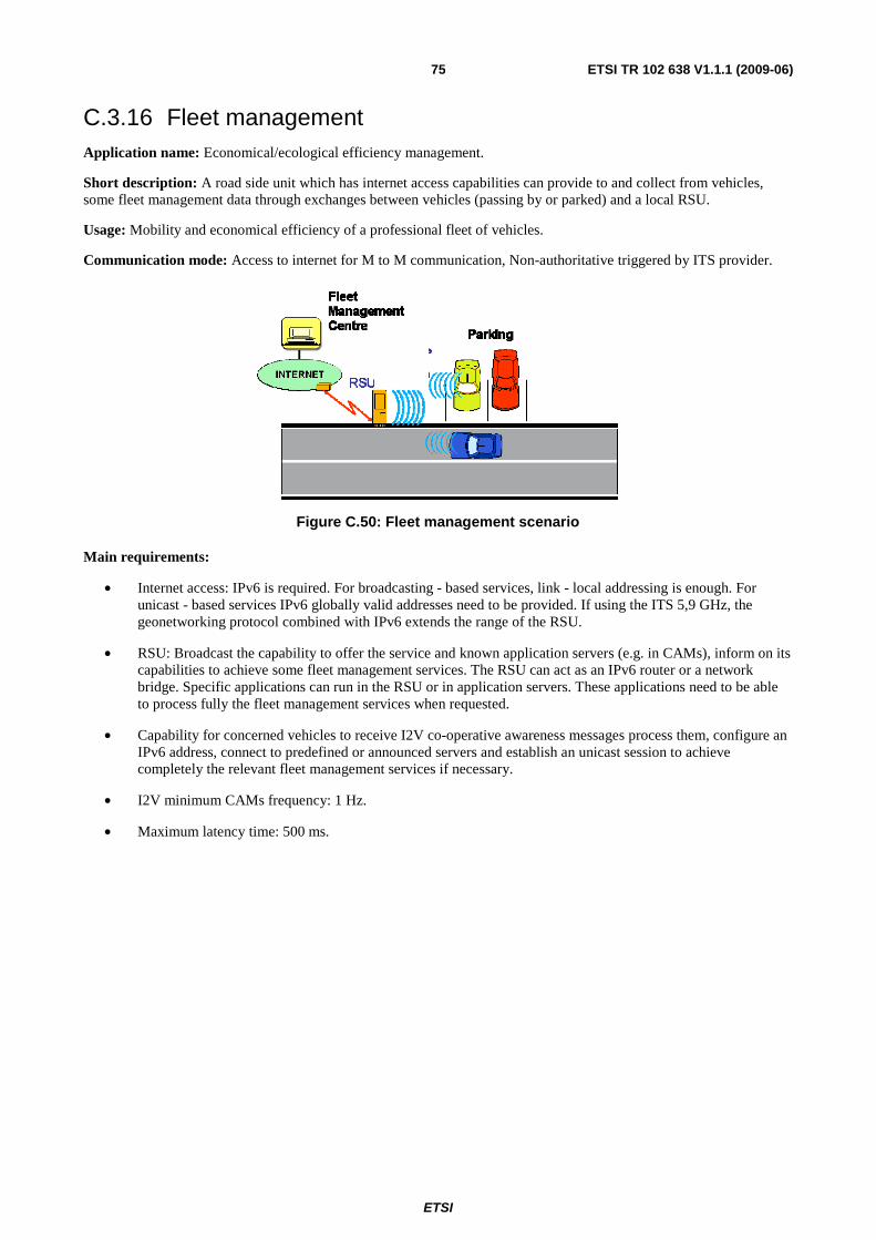
ETSI
ETSI TR 102 638 V1.1.1 (2009-06) 75
C.3.16 Fleet management Application name: Economical/ecological efficiency management.
Short description: A road side unit which has internet access capabilities can provide to and collect from vehicles, some fleet management data through exchanges between vehicles (passing by or parked) and a local RSU.
Usage: Mobility and economical efficiency of a professional fleet of vehicles.
Communication mode: Access to internet for M to M communication, Non-authoritative triggered by ITS provider.
Figure C.50: Fleet management scenario
Main requirements:
• Internet access: IPv6 is required. For broadcasting - based services, link - local addressing is enough. For unicast - based services IPv6 globally valid addresses need to be provided. If using the ITS 5,9 GHz, the geonetworking protocol combined with IPv6 extends the range of the RSU.
• RSU: Broadcast the capability to offer the service and known application servers (e.g. in CAMs), inform on its capabilities to achieve some fleet management services. The RSU can act as an IPv6 router or a network bridge. Specific applications can run in the RSU or in application servers. These applications need to be able to process fully the fleet management services when requested.
• Capability for concerned vehicles to receive I2V co-operative awareness messages process them, configure an IPv6 address, connect to predefined or announced servers and establish an unicast session to achieve completely the relevant fleet management services if necessary.
• I2V minimum CAMs frequency: 1 Hz.
• Maximum latency time: 500 ms.
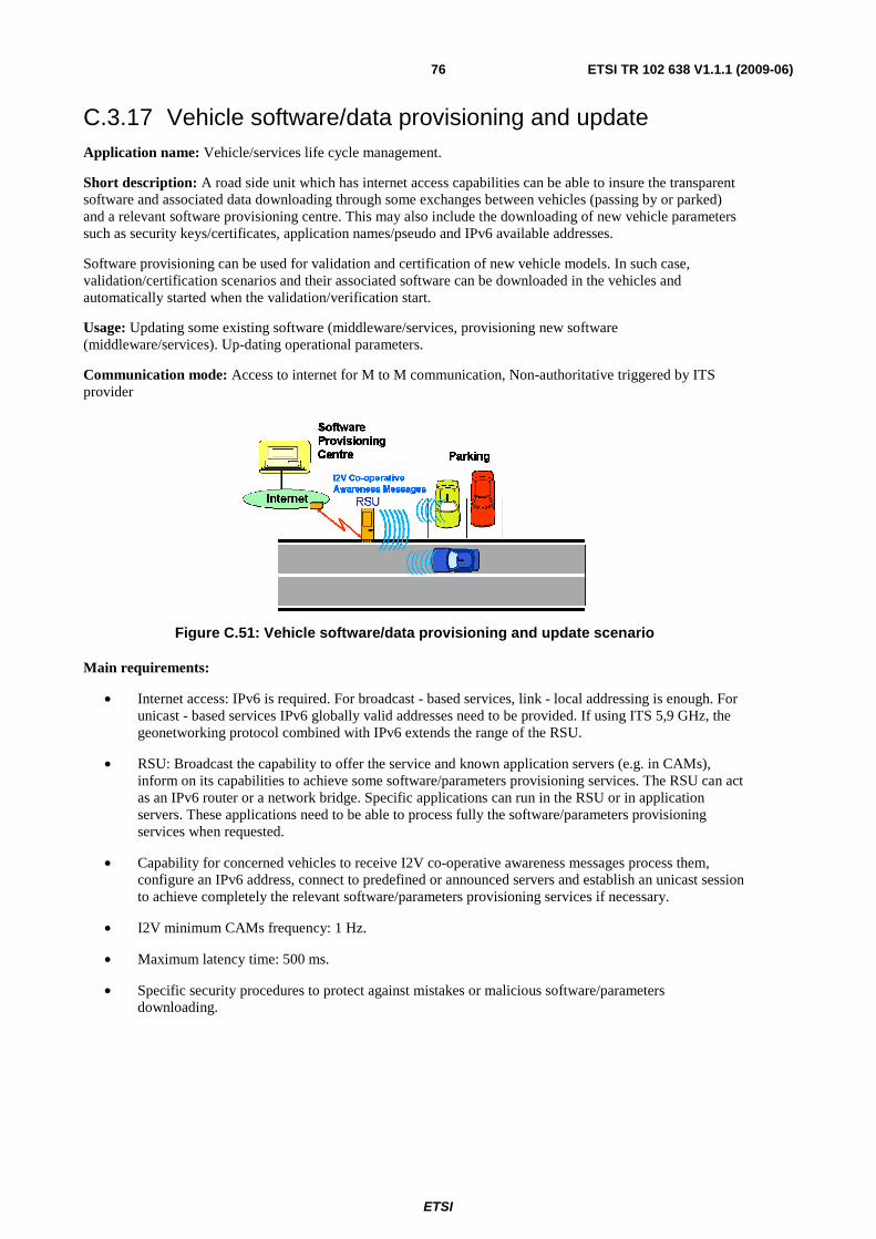
ETSI
ETSI TR 102 638 V1.1.1 (2009-06) 76
C.3.17 Vehicle software/data provisioning and update Application name: Vehicle/services life cycle management.
Short description: A road side unit which has internet access capabilities can be able to insure the transparent software and associated data downloading through some exchanges between vehicles (passing by or parked) and a relevant software provisioning centre. This may also include the downloading of new vehicle parameters such as security keys/certificates, application names/pseudo and IPv6 available addresses.
Software provisioning can be used for validation and certification of new vehicle models. In such case, validation/certification scenarios and their associated software can be downloaded in the vehicles and automatically started when the validation/verification start.
Usage: Updating some existing software (middleware/services, provisioning new software (middleware/services). Up-dating operational parameters.
Communication mode: Access to internet for M to M communication, Non-authoritative triggered by ITS provider
Figure C.51: Vehicle software/data provisioning and update scenario
Main requirements:
• Internet access: IPv6 is required. For broadcast - based services, link - local addressing is enough. For unicast - based services IPv6 globally valid addresses need to be provided. If using ITS 5,9 GHz, the geonetworking protocol combined with IPv6 extends the range of the RSU.
• RSU: Broadcast the capability to offer the service and known application servers (e.g. in CAMs), inform on its capabilities to achieve some software/parameters provisioning services. The RSU can act as an IPv6 router or a network bridge. Specific applications can run in the RSU or in application servers. These applications need to be able to process fully the software/parameters provisioning services when requested.
• Capability for concerned vehicles to receive I2V co-operative awareness messages process them, configure an IPv6 address, connect to predefined or announced servers and establish an unicast session to achieve completely the relevant software/parameters provisioning services if necessary.
• I2V minimum CAMs frequency: 1 Hz.
• Maximum latency time: 500 ms.
• Specific security procedures to protect against mistakes or malicious software/parameters downloading.
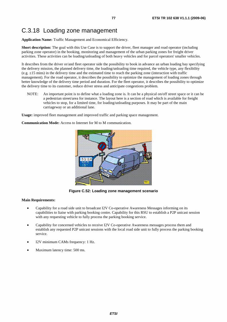
ETSI
ETSI TR 102 638 V1.1.1 (2009-06) 77
C.3.18 Loading zone management Application Name: Traffic Management and Economical Efficiency.
Short description: The goal with this Use Case is to support the driver, fleet manager and road operator (including parking zone operator) in the booking, monitoring and management of the urban parking zones for freight driver activities. These activities can be loading/unloading of both heavy vehicles and for parcel operators' smaller vehicles.
It describes from the driver or/and fleet operator side the possibility to book in advance an urban loading bay specifying the delivery mission, the planned delivery time, the loading/unloading time required, the vehicle type, any flexibility (e.g. ±15 mins) in the delivery time and the estimated time to reach the parking zone (interaction with traffic management). For the road operator, it describes the possibility to optimize the management of loading zones through better knowledge of the delivery time period and duration. For the fleet operator, it describes the possibility to optimize the delivery time to its customer, reduce driver stress and anticipate congestions problem.
NOTE: An important point is to define what a loading zone is. It can be a physical on/off street space or it can be a pedestrian street/area for instance. The layout here is a section of road which is available for freight vehicles to stop, for a limited time, for loading/unloading purposes. It may be part of the main carriageway or an additional lane.
Usage: improved fleet management and improved traffic and parking space management.
Communication Mode: Access to Internet for M to M communication.
Figure C.52: Loading zone management scenario
Main Requirements:
• Capability for a road side unit to broadcast I2V Co-operative Awareness Messages informing on its capabilities to liaise with parking booking centre. Capability for this RSU to establish a P2P unicast session with any requesting vehicle to fully process the parking booking service.
• Capability for concerned vehicles to receive I2V Co-operative Awareness messages process them and establish any requested P2P unicast sessions with the local road side unit to fully process the parking booking service.
• I2V minimum CAMs frequency: 1 Hz.
• Maximum latency time: 500 ms.
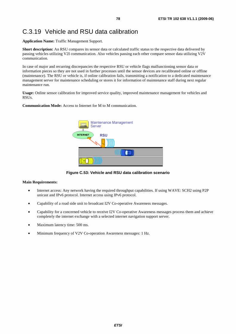
ETSI
ETSI TR 102 638 V1.1.1 (2009-06) 78
C.3.19 Vehicle and RSU data calibration Application Name: Traffic Management Support.
Short description: An RSU compares its sensor data or calculated traffic status to the respective data delivered by passing vehicles utilizing V2I communication. Also vehicles passing each other compare sensor data utilizing V2V communication.
In case of major and recurring discrepancies the respective RSU or vehicle flags malfunctioning sensor data or information pieces so they are not used in further processes until the sensor devices are recalibrated online or offline (maintenance). The RSU or vehicle is, if online calibration fails, transmitting a notification to a dedicated maintenance management server for maintenance scheduling or stores it for information of maintenance staff during next regular maintenance run.
Usage: Online sensor calibration for improved service quality, improved maintenance management for vehicles and RSUs.
Communication Mode: Access to Internet for M to M communication.
Figure C.53: Vehicle and RSU data calibration scenario
Main Requirements:
• Internet access: Any network having the required throughput capabilities. If using WAVE: SCH2 using P2P unicast and IPv6 protocol. Internet access using IPv6 protocol.
• Capability of a road side unit to broadcast I2V Co-operative Awareness messages.
• Capability for a concerned vehicle to receive I2V Co-operative Awareness messages process them and achieve completely the internet exchange with a selected internet navigation support server.
• Maximum latency time: 500 ms.
• Minimum frequency of V2V Co-operation Awareness messages: 1 Hz.
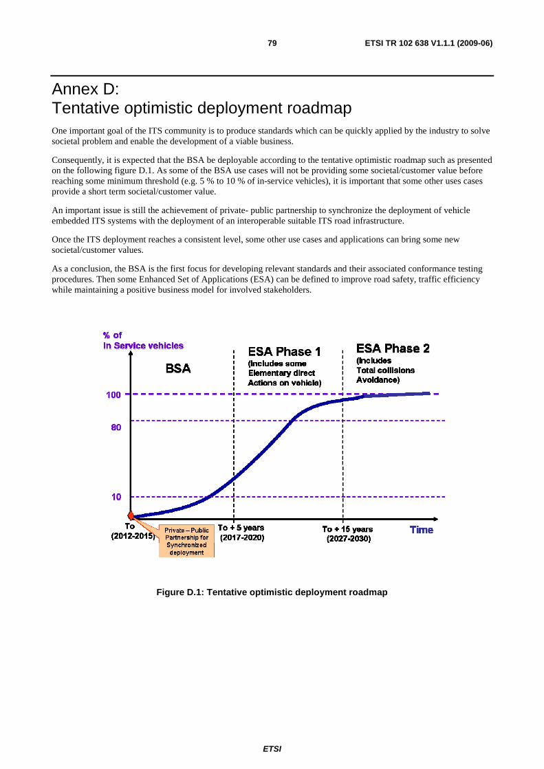
ETSI
ETSI TR 102 638 V1.1.1 (2009-06) 79
Annex D: Tentative optimistic deployment roadmap One important goal of the ITS community is to produce standards which can be quickly applied by the industry to solve societal problem and enable the development of a viable business.
Consequently, it is expected that the BSA be deployable according to the tentative optimistic roadmap such as presented on the following figure D.1. As some of the BSA use cases will not be providing some societal/customer value before reaching some minimum threshold (e.g. 5 % to 10 % of in-service vehicles), it is important that some other uses cases provide a short term societal/customer value.
An important issue is still the achievement of private- public partnership to synchronize the deployment of vehicle embedded ITS systems with the deployment of an interoperable suitable ITS road infrastructure.
Once the ITS deployment reaches a consistent level, some other use cases and applications can bring some new societal/customer values.
As a conclusion, the BSA is the first focus for developing relevant standards and their associated conformance testing procedures. Then some Enhanced Set of Applications (ESA) can be defined to improve road safety, traffic efficiency while maintaining a positive business model for involved stakeholders.
Figure D.1: Tentative optimistic deployment roadmap
ETSI
ETSI TR 102 638 V1.1.1 (2009-06) 80
Annex E: Bibliography ISO/TS 18234-4: "Traffic and Travel Information (TTI) - TTI via Transport Protocol Expert Group (TPEG) data-stream - Part 4: Road Traffic Messages (RTM Application)".
Car2Car Communication Consortium manifesto version 1 of the 21st May 2007.
NOTE: http://www.car-2-car.org.
"Car to Car Communication - market introduction and success factors, 5th European congress and exhibition on Intelligent Transport Systems and Services (European ITS 2005), June 2005". K.Matheus, R.Morich, I.Paulus, C.Menig, A.Lübke, B.Rech, W.Specks.
PREparation for DRIVing implementation and evaluation of C-2-X communication technology: "PRE-DRIVE C2X deliverable D 4.1", Detailed description of selected applications and corresponding technical requirements.
ETSI TS 102 665: "Intelligent Transport Systems (ITS); Vehicular Communications; Architecture".
ETSI
ETSI TR 102 638 V1.1.1 (2009-06) 81
History
Document history
V1.1.1 June 2009 Publication


