Bedienungsanleitung 1 Mit Software Obelisk programmierbar Mode d’emploi 31 Programmation avec logiciel Obelisk Operating instructions 59 Time switch programming with software Obelisk Istruzioni d’uso 87 Programmazione con software Obelisk Gebruiksaanwijzing 115 Programmering met software Obelisk TR 644 S TR 644 S DCF TR 608 top TR 610 top TR 611 top TR 622 top TR 030 top TR 641 S Ref. Nr. 641 0 001 TR 641 S DCF Ref. Nr. 641 0 301 310 548 02 Teil 1 von 2
� Mode d’emploi 31Programmation avec logiciel Obelisk
� Operating instructions 59Time switch programming with
software Obelisk
� Istruzioni d’uso 87Programmazione con software Obelisk
� Gebruiksaanwijzing 115Programmering met software Obelisk TR 644 S TR 644 S DCF TR 608 top TR 610 top TR 611 top TR 622 top TR 030 top
TR 641 SRef. Nr. 641 0 001
TR 641 S DCFRef. Nr. 641 0 301
310
548
02Te
il 1
von
2
59
1.0 Description of the Product 2.0 Features
1 Display DCF 77 reception (only TR 641 S DCF)2 Display data exchange with Obelisk3 Display hours4 Interface5 Cursor for program selection6 Display date day7 Display date month8 Display year9 Random indicator /P 1 .. 9 / Manual ON (H o / Manual OFF (H p)
10 Display status ON =o OFF =p11 Permanent switching OFF-AUTO-ON12 Buttons 0 – 9 for program entry13 Battery compartment14 Button for entry of date switchings15 Button for entry of priority programs/changes16 Button for cancellation of programs and program steps17 Connection terminal for DCF 77 antenna (only TR 641S DCF)18 Button for entry of input19 RES = Reset / the micro-processor makes a defined new start20 Program selection button for menu selection21 Display for pulse programming22 Cursor for display of days of the week 1 = Monday, 2 = Tuesday..23 Display 1 x shows single switchings
– 1-Channel-Yearly Time Switch
– Time switch programming or PC programming using WIN 95 / WIN 98 / WIN NTwith Obelisk software
– The time switch can be programmed up to the year 2063 in advance
– Data transfer and security possible with Obelisk storage card
– Data can be transferred from time switch to time switch, from time switch to PCand vice versa
– 324 switchings for free block formation of week days
– Permanent switching times by means of EEPROM
– Day/Week/Year program
– Option: Public holidays will be activated automatically
– Random program
– Pulse program
– Switching times: ON or OFF delay
– 1x-function for all date-related switching times
– 10 priority programs consisting of 10 individual weekly programs
– Time limited permanent switching ON/OFF
– Approx. 1.5 years battery reserve by means of exchangeable environmentally fri-endly lithium cell
– Option: TR 641 S DCF 77 radio controlled (with Radio antenna t 907 0 243)
5.0 Initial Operation (page 64)5.1 Overview of menu selection (page 64)5.2 Entry adjustment (page 64)5.3 Setting date and time (page 65)5.4 Selection schedule for automatic Summer/Winter time (page 65)5.5 Changing automatic Summer/Winter time (page 66)5.6 Changing date/time (page 66)5.7 Radio time switch (page 67)5.8 Connection and adjustment of the radio antenna (page 67)5.9 Initial operation of the radio time switch TR 641 S DCF (page 68)5.10 Forced transmitter call (page 69)
6.0 Manual Intervention in the Program (page 69)6.1 Permanent ON/OFF (page 69)6.2 Manual ON/OFF (override switching) (page 69)6.3 Random Program (page 69)6.4 Random Program Start (page 70)6.5 Stop Random program/override switching (page 70)6.6 Locking/unlocking the keyboard (page 70)6.7 Random Program (page 71)6.8 Random Program start (page 71)6.9 Stop Random Program / override switching (page 71)
7.0 Programming (page 72)7.1 Programming weekly program (page 72)7.2 Programming data program (page 73)7.3 Programming single switching times (page 73)7.4 Programming pulse program (page 74)
8.0 Priority program (page 74)8.1 Programming weekly program with weekly program P1-P9 (page 76)8.2 Setting time period for the weekly program (page 76)
A. Recurring annually (Seite 76)B. Program only in specified year (Seite 77)C. Stipulating public holiday without fixed date (Seite 77)
8.3 Time limited permanent switching (page 78)
9.0 Program Interrogation (page 78)9.1 Whole program interrogation (page 78)9.2 Interrogation of designated switching times (page 78)9.3 Interrogation of channel related date program (page 79)9.4 Interrogation of date completely (page 79)9.5 Interrogating weeky program with priority (page 79)
10.0 Changing a stored program (page 80)
11.0 Cancellation (page 81)11.1 Cancellation of individual switching times (page 81)11.2 Cancellation of date program (page 81)11.3 Cancellation of priority program (page 82)11.4 Cancel everything (page 82)
12.0 Data Exchange/External Data Security (page 83)12.1 Recording data from time switch on the memory card (page 83)12.2 Reading data from memory card into the time switch (page 83)12.3 Preview programming with Software OBELISK (page 83)
13.0 Tips and Dodges (page 84)
14.0 Glossary (page 85)
15.0 Table of errors (page 86)
61
3.0 Application / installation
Time switches switch ON, OFF and over connected electrical units, depending ontime, on a daily or weekly cycle and related to date.
– The time switch TR 641 S / TR 641 S DCF may only be used in dryareas
– Time switches are suitable for use in environmental conditions with nor-mal pollution.
– The time switch TR 641 S / TR 641 S DCF is suitable for mounting onthe 35 mm top-hat rail (DIN EN 50022)
– Wall mounting with installation kit 907 0 053
3.1 Safety instruction
The connection and installation of electrical equipment may beeffected only by a qualified electrician. National regulationsand any valid safety conditions should be observed.Interference with and changes to the product will result in can-cellation of the guarantee.
3.2 Installation instructions
In spite of expensive protection measures, exceptionally strong magneticfields can lead to the destruction of the micro-processor controlled timeswitch.
We therefore recommend attention be given to the following points beforeinstallation:
– Use separate lead for the mains voltage supply.
– Suppress inductive loads with suitable RC filters.
– Do not mount product in direct proximity to sources of interference as e. g.transformers, contactors, PCs and TV and communication equipment.
– After suffering intereference, we recommend, before re-setting, a RESET witha new initial set up (chapter 5.3).
– Strongly heat-generating products on the right side of the product shorten thelife of the battery.
3.3 Electrical connection
National regulations and any valid safety conditions must beobserved.
62
3.4 Technical data
Description: Yearly Time SwitchProgram Type: Day/WeekSupply Voltage: 230 V~ ± 10 %Nominal Frequency: 50 – 60 HzPower Consumption: Approx. 3 VASwitching Capacity: 16 (10) A, 250 V~Contact Material: AgSnO2Contact Type: Change-OverTime Base: QuartzMemory Locations: 324Minimum Switching Time: 1 second/minuteMinimum Pulse: 1 secondSwitching Accuracy: Accurate to the secondAccuracy: ± 1 sec./day at 20° CPower Reserve: Lithium Cell 1.5 years at 20° CPermissible Ambient Temperature: – 10° C ... + 50° C (–10T50)Protection Class: II if installed according to EN 60335Enclosure Type: IP 20 in accordance with EN 60529Type: 1 BSTU in accordance with EN 60730-1, -2, - 7
TR 641 S DCFTime Base: Radio exact (with power reserve quartz operated)Max. Distant of the radio antenna: 200 mEnclosure Type: IP 54 in accordance with EN 60529Power Supply 907 0 182: NecessaryMax. Loading: 10 products.
Note deviating technical data on the rating plateRights to technical improvements are reserved.
NoteThe time switches conform to the European Regulations 73/23/EWG (low volta-ge rules) and 89/336/EWG (EMV-Regulations).If the time switches are used with other products in one installation, attentionmust be given to ensure that the whole installation does not cause radio interfe-rence.
3.5 Illustration of dimensions
Dotted lines correspond to the dimensions of mounting Kit 907 0 053
63
4.0 Power reserve
In the event of a power failure, the battery back-up provides for the maintenaceof correct time (approx. 1.5 years). Even without power and with a drained bat-tery, the switching times remain permanently stored.
4.1 Battery loading
– Note the polarity of the lithium battery.
– Insert the lithium battery into the holder (see diagram 1).
– Push the battery holder into the battery compartment.
– Press the battery holder down, untl it audibly locates.
4.2 Battery changing
Important Instructions
Battery changing with mains voltageAll memorised program data is maintained
Battery changing without mains voltageNote: date and time are lost.
1. Lift the battery draw with a suitable screw driver (see diagram 3).
2. Remove the lithium battery from the holder (see diagram 2).
3. Note the polarity of the new lithium cell (Order No. 9 883 003).
4. Insert the Lithium battery into the holder (see diagram 1).
5. Push the battery holder into the battery compartment.
6. Press the battery holder down until it audibly locates.
7. Dispose of lithium battery in an environmentally friendly way.
Dia. 3
Dia. 2
Dia. 1
64
5.0 Initial operation
Ensure that the lithium battery is located (Chapter 4.1)
5.1 Overview of menu selection
By pressing the button v the Cursor ▲ can be moved.With each touch of the button, the cursor moves one menu position.
Auto (Automatic Program)– Programmed switching times determine the
switching programm– Switching override (Manual ON/OFF)– Random ON/OFF
Prog – Programming of date, weekly and 1x switchingtimes
– Programming of date, weekly pulses, 1x pulse,ON and OFF switching delays
P – e.g. public holiday, vacation, or holiday program
s/f – Programming and change of Summer/Wintertime switching
Ending Programming: use v button, and place cursor ▲ into followingposition .
5.2 Entry adjustment
The TR 641 S / TR 641 S DCF contains a prompt facility. Follow the flashingsymbols. They show the programming sequence.
Entry Adjustment:
What to do when a wrong value has been entered in error?
Cancel the program step again:– press button CL = one step back– press button CL repeatedly = repeated steps back
When wrong value flashes:– enter correct value with buttons 0 .. 9
or when programming channels or week-days:or in the event of a wrong entry:– press the same button again
Note:Only the last entry will be cancelled
Cursor below symbol:
65
5.3 Setting date and time
On initial operation press button RES with a pointed object e.g. pencil, and after-wards release it.Initial operation of the Radio controlled Time switch TR 641S DCF see chapter 5.7.
Example:The time switch is to be set up on 19.05.2000 at 9.25
1
1
12
2
23
3
34
4
45
5
56
6
67
7
77
7
7
C
Auto
1 2 3 4 5 6 77
1, 9
0, 5 0, 0
0, 9 2, 5
Enter
Res.
Note:
After the initial operation (Chapter 5.3) automatic Summer/Winter time is alreadyprogrammed.
Basic setting is for Central Europe: dat 1.
If another or no change over standard is required, this can be changed at any time,as described in Chapters 5.4 – 5.5.
date month
hour
store
date day
year
minute
5.4 Selection schedule for automatic summer/ winter time
Setting Commen- Commen- Areacement cement
dat 0 no change no change Use for radiocontrolled version
dat 1 last Sunday last Sunday EUin March in October2 AM ➔ 3 AM 3 AM ➔ 2 AM
dat 2 last Sunday 4th Sundayin March in October UK1 AM ➔ 2 AM 2 AM ➔ 1 AM
dat 3 1st Sunday last Sunday Northin April in October America2 AM ➔ 3 AM 3 AM ➔ 2 AM
dat 4 individual Summer/Winter time table,programmable only with Obelisk software
66
5.5 Changing automatic summer/ winter time
Default: TR 641 S: dat 1
Default: TR 641 S DCF: dat 0
Select the new switching time (Chapter 5.4)
Example: basic setting dat 1Change to: dat 0
Note: Select dat 0 for radio controlled version
0 Enter
Dat.6x
Store
AdjustSelect
New dat 0
With button v return to the automatic programme.
5.6 Changing date / time
With the cursor in Pos.n, any flashing value, the actual time or date, can bechanged with the buttons 0 .. 9.
1 11
11
1
1
1
1
1
2 22
22
2
2
2
2
2
3 33
33
3
3
3
3
3
4 44
44
4
4
4
4
4
5 55
55
5
5
5
5
5
6 66
66
6
6
6
6
6
7 77
77
7
7
7
7
7
7 77
77
7
7
7
7
7
AutoAuto
AutoAuto
ProgProg PP??
Dat. 0, 9
2
7
1X
2,0
Enter
Enter
Enter
1 2 3 4 5 6 7
CC
C1
– press Enter repeatedly, until the cursor is below Auto– or follow the line and change the actual time
Select Dat
Date Day
Store month
Store year Store
Adjust
Adjust
Hour
Change date e.g. from19.5.2000 to 20.5.2000
Change time only e.g.from 9.25 to 9.27
67
5.7 Radio Time Switch
The operation of the radio time switch is exactly the same as with the TR 641S.The correct time, date and Summer-/Wintertime change-over set themselvesautomatically with me DCF 77 radio receiver.
Interesting Details:
– Accuracy of the radio receiver +/– 1 sec. in 1,000,000 years
– Transmitter location is Mainflingen near Frankfurt
– Transmitting radius of the transmitter approx. 1000 km
– Synchronisation is effected after initial setting-up and then daily atnight.
5.8 Connection and Adjustment of the Radio Antenna
We recommend the following mounting positions:
– outside the control box (at least 4 m away)– under the roof– or in a protected position out of doors
Avoid mounting positions near:
– radio transmitting installations– radiological equipment– television and personal computers
1. Use only t antenna No: 907 0 243 to the radio controlled timeswitch
2. Use a 2 lead cable for connection3. Attach antenna cable to the terminal, connect power supply NT DCF 77.
In this case, set the summer-/ winter change to the correct changeover standard,see chapter 5.3/ 5.4
In this case, set the summer-/ winter change to the correct changeover standard,see chapter 5.3/ 5.4
TR 641 S - TR 641 S DCF
A. Operation without DCF 77 radio reception
B. Operation with DCF 77 radio reception
C. Adjustment of one time switch to the radio antenna
1. Connect first one time switch to the operating voltage 230 V~.
2. Connect radio antenna to this time switch, polarity does not matter.
3. The connection of the other devices to t DCF antenna 907 0 243
may take the form of star, bus or tree topology.
4. Connect the other time switches to radio antenna.
5. However the LED lights up, polarity of this antenna connection must be changed.
6. Connect the other time switches to the operating voltage 230 V~.
D. Adjustment of up to 10 time switches to the radio antenna
68
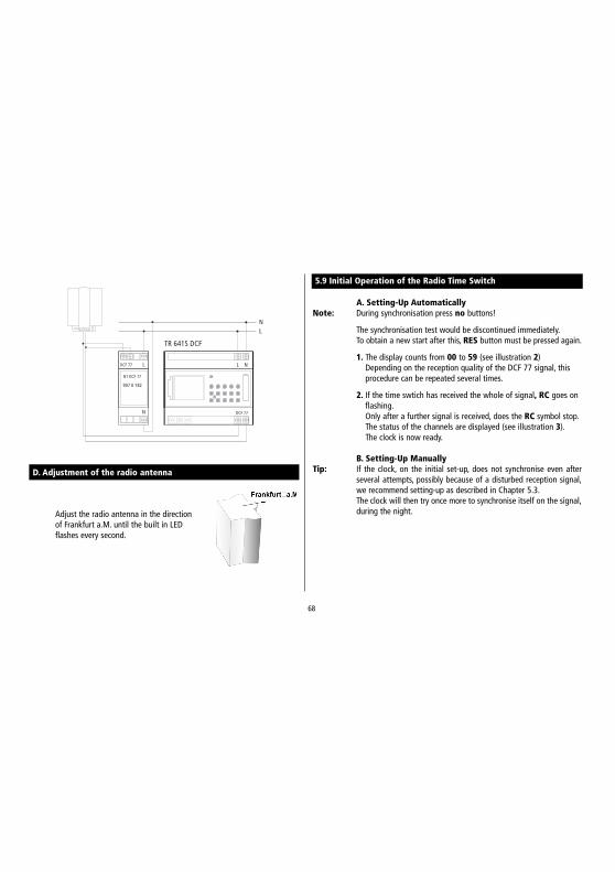
D. Adjustment of the radio antenna
N
N
L
L
DCF 77
TR 641S DCF
N
LDCF 77
907 0 182
NT DCF 77
Adjust the radio antenna in the directionof Frankfurt a.M. until the built in LEDflashes every second.
A. Setting-Up AutomaticallyNote: During synchronisation press no buttons!
The synchronisation test would be discontinued immediately.To obtain a new start after this, RES button must be pressed again.
1. The display counts from 00 to 59 (see illustration 2)Depending on the reception quality of the DCF 77 signal, thisprocedure can be repeated several times.
2. If the time swtich has received the whole of signal, RC goes onflashing.Only after a further signal is received, does the RC symbol stop.The status of the channels are displayed (see illustration 3).The clock is now ready.
B. Setting-Up ManuallyTip: If the clock, on the initial set-up, does not synchronise even after
several attempts, possibly because of a disturbed reception signal,we recommend setting-up as described in Chapter 5.3.The clock will then try once more to synchronise itself on the signal,during the night.
5.9 Initial Operation of the Radio Time Switch
69
5.10 Forced Transmitter Call
The synchronisation of the time switch is effected after the initial setting-up, thendaily between 1.58 and 3.13.A radio synchronisation can be called up manually during the day(transmitter call).Start of the Transmitter Call1. Press Dat Button for approx. 3 secs.2. then releaseThe timeswitch synchronises itself on the DCF 77 signal.In the LCD display can be seen:The RC symbol flashes only during a DCF 77 synchronisation!If the time switch has synchronised itself, a program review takes place.The channels take on, afterwards, the specified switching positions, from the indi-vidual program.The RC symbol is permanently in the LCD display.
Example: The time switch has synchronised itself on 19.5.2000 at 9.25.
1 2 3 4 5 6 7
C
Auto
Res.
2)
3)
6.0 Manual intervention in the program
6.1 Automatic operation (standard setting)
The channel C take in the switching condition provided the stored time program.
6.2 Permanent ON
The channel C can be manually switched in each menu to permanently ON. Apermanent switching has highest priority. The channel remains in the perma-nently ON switching position until manually cancelled.The status display in the LCD (p / o) is not adjusted.
6.3 Permanently OFF
The channel C can be manually switched in each menu to permanently OFF. Apermanent switching has highest priority. The channel remains in the perma-nently OFF switching position until manually cancelled.The status display in the LCD (p / o) is not adjusted.
Time limited permanent switchings ON/OFF (see Chapter 8.3)
70
6.4 Manual ON (override switching)
The channel C can be switched ON manually in the automatic program. In whichcase, the symbol H = hand appears in the display.An override switching is cancelled again by the next switching command. The Hdisplay is turned off.
Select Status: Button 1 = Switch ON
ON
6.5 Manual OFF (override switching)
The channel C can be switched OFF manually in the automatic program. An over-ride switching in the automatic program is corrected again by the next switchingcommand. (The H symbol is turned off).
Select Status: Button 0 = Switch OFF
OFF
11 22 33 44 55 66 77
C
Auto
1
11 22 33 44 55 66 77
C
Auto
0
Auto
Auto
6.6 Random program
General CommentA random program causes the time switch to switch ON or OFF at random bet-ween one or more pairs of switchings (ON and OFF switching time).Duration of the random ON and OFF switching time approx. 10 – 120 minutes.
Example:Between 19.00 and 22.00 random ON (display:r)Between 0.00 and 06.00 random ON (display:r)
Programmed switching pairs
RandomProgram
RandomProgram
CDat.
Auto
71
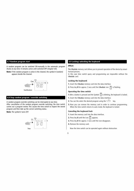
6.7 Random program start
A random program can be switched ON manually in the automatic program(Auto) at any time. It remains active until switched OFF (chapter 6.8).
Note: If the random program is active in the channel, the symbol r (random)appears beside the channel.
StartRandom
6.8 Stop random program / override switching
A random program override switching can be interrupted at any time.After cancellation of the random program override switching, the time switchcarries out a program review. This causes the time switch to inspect the storedprogram and then take up the correct switching status.
Note: The symbol r turns OFF
C
Auto
CL
Stop
6.9 Locking/ unlocking the keyboard
Effect:
The Obelisk memory card allows you to prevent operation of the device by unaut-horized persons.In this case time switch query and programming are impossible without theObelisk card.
Locking the keyboard:
1. Insert the Obelisk memory card into the data interface.
2. Press key 8 for approx. 3 secs until the Obelisk icon is flashing.
Operating the time switch
If after a button is pressed and the Symbol is blinking, the keyboard is locked.
1. Insert the Obelisk memory card into the data interface.
2. You can the select the desired program using the v key.
3. Now you can remove the memory card in order to continue programming.When the time switch returns to auto mode, the keyboard is locked.
Canceling the keyboard lock
1. Insert the memory card into the data interface.
2. Press key 8 until the icon appears.
3. Press key 8 for approx. 3 secs until the icon disappears.
4. Remove the memory card.
Now the time switch can be operated again without obstruction.
72
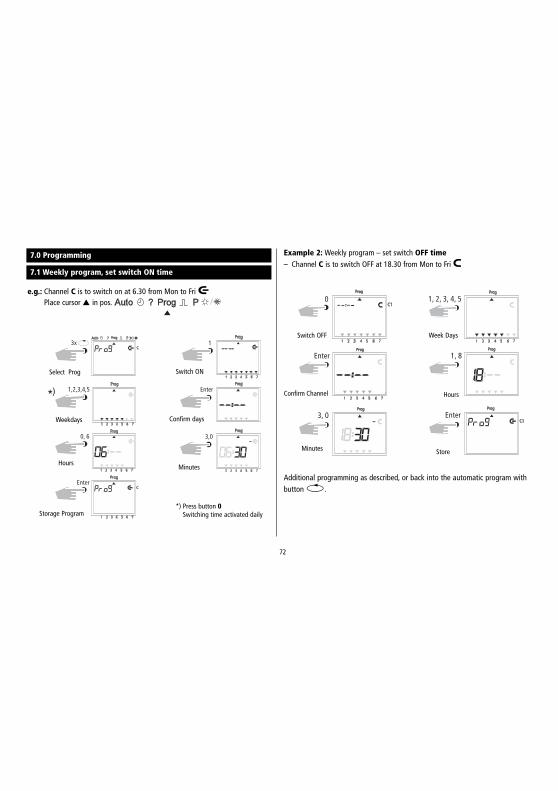
7.0 Programming
7.1 Weekly program, set switch ON time
e.g.: Channel C is to switch on at 6.30 from Mon to Fri oPlace cursor ▲ in pos.
Select Prog Switch ON
Confirm days
Minutes
*) Press button 0Switching time activated daily
Weekdays
Hours
Storage Program
Example 2: Weekly program – set switch OFF time– Channel C is to switch OFF at 18.30 from Mon to Fri p
Additional programming as described, or back into the automatic program withbutton v.
Confirm Channel
Week Days
Hours
Store
Switch OFF
Minutes
73
7.2 Programming date program
Example.: Channel C is to switches ON on the 1.5 at 7.30Place cursor ▲ in pos.
Additional programming as described or back into the automatic program withbutton v.
Select Prog. switch ON
ON
Date Day
Hours
Store
Date
Date Month
Minutes
7.3 Programming single switching time
Example: Channel C, 1 switches ON on the 10.5 at 8.30Note: Only date related switching times can be programmed with the fun-
ction 1x see illustration 8. Once the switching time is effected, itcancels itself automatically at mid-night.
1 2 3 4 5 6 7
C
C C
Prog
Prog
Prog
Prog Prog
Prog Prog
Prog ProgProg
Enter
1
Dat 1, 0
0, 5 0, 8
3, 0 1
3x
Select Prog switch ON
Date Date Day
Date Month Hours
Minutes 1 x
Store
Additional programming as described orback into the automatic program withbutton v
74
7.4 Programming pulse program
Example: Channel C pulse duration: 5 secs from Mon to Fri at 7.15.Place cursor ▲ in pos.
Note After a time adjustment, pulses are only effected, which are programmedat least one minute after the time adjustment.
Select Switch ON
Confirm Days
Minutes
Store
Week Days
Hours
Pulse 5 sec.
8.0 Priority program
With the TR 641 S / TR 641 S DCF up to 9 different weekly programs can beperformed in addition to the normal weekly program. A firm weekly programP1 ... P9 can be requested at any fixed periods of time.
That is, the programming consists of:
1. Setting the weekly program (see Chapter 8.1)2. Setting commencement and completion date (see Chapter 8.2)
If the time period of several weekly programs cut across one another, the pro-gram with the highest index number prevails e.g. weekly program P9 prevailsover weekly program P3.
In order to maintain control, we recommend that the various weekly programsare noted in the table at the end of the user instructions.
Switching times are executed in the following order:
– Permanent switching– Time limited permanent switching. Chapter 8.3 (out priority over ON).– Date switching times. Chapter 7.2 (out priority over ON).– 1x switching times. Chapter 7.3.– Weekly program with priority. Chapter 8.2/8.3 (P9 priority over P1).– Weekly program. Chapter 7.1/7.2.– etc.
75
Weekly program schedule with priority
Highes
t Prio
rity
weekly program P9
weekly program P8
weekly program P7weekly program P6
weekly program P5
weekly program P3
weekly program P2
weekly program P1
weekly program P4
Channel C switch ONMonday-Friday 6.30pulse duration 5 secs.
Channel C switch ONMonday-Friday at 7.15pulse duration 5 secs.
Channel C at ON o16.15 daily.
Channel C at OFF 20.00 p
Starte.g. 8.4
Finishe.g. 27.5
Starte.g. 21.7
Finishe.g. 7.9
StandardWeekly Program
Weekly ProgramP3
StandardWeekly Program
Weekly ProgramP4
StandardWeekly Program
When changing to a new weekly program (e.g. on 8.4 at 0.00 hr), the channel inquestion is switched as if the new weekly program has been valid for some time.This means the new weekly programme makes a review of the program.
Overview TR 641 S – TR 641 S DCF
weekly program„standard“
weekly program„Priority 1“
weekly program„Priority 2“
weekly program„Priority 3“
weekly program„Priority 4“
weekly program„Priority 5“
weekly program„Priority 6“
weekly program„Priority 7“
weekly program„Priority 8“
weekly program„Priority 9“
Priority timesP1-P9
Dateswitching
timesPermanently
ON/OFF
ON
OFF
RELAY
76
8.1 Programming weekly program with priority P1 .. P9
Example Channel C switches on daily at 8.15Priority sequence P1.
Note: Pulse switching times canalso be fixed with prioritysequence.For weekly programs withpriority, any number ofON/OFF switching com-mands can be specified.
Select Prog Switch ON
Daily Hours
Minutes Priority P1
Store
The time period of a weekly program P1 .. P9 is fixed by entering a commence-ment and finishing date. The weekly program begins at 0.00 on the commence-ment date and ends at 2400 on the finishing date.
Example: As opposed to the normally active program on Channel C1 from8 April until 27 May, the individual priority program with index P1 is to beco-me effective. In the fixed time period with priority sequence P1 .. P9, the wholestandard program (without priority sequence) is suppressed.
8.2 Setting Time Period for Weekly Program P1 .. P9
Additional programming as described or with button v back into the auto-matic program.
7)
Select P
Date Start
Confirm
Confirm
Date end
Store
A. Recurring annually
CC
C
P
P
P P
P
P
0, 8,0, 4
2, 7, 0, 5
Enter
5x
P
CC
C
P
P
P P
P
P
Enter
1
P
1
Program 1
77
C
C
P P
PP
P P
1
2,3,0, 4 Dat
2 Enter
5x
Example: Following this measure, a public holiday such as Easter 2000(not a fixed date) will be activated automatically and will exe-cute, e.g., program P2.
C. Stipulating public holidays without a fixed date
ON
Date start
Program 2 Confirm
Symbol„no fixed date“
Select P
Note: Programming of public holidays without fixed dates only needs to be car-ried out once, e.g. following initial start-up.This applies to holidays connected with Easter such as Ascension, Whitsun,Corpus Christi, Ash Wednesday, Good Friday etc. Program the date of allof these holidays that do not have a fixed date once only for the currentyear.
C
C
P P
PP
P P
8, 4, 0, 0 2, 7, 0, 5
2 Enter
5x 1
Example: Only in year 2000 from 8th April to 27th May, e.g. the weeklyprogram P2 activated.
B. Weekly program only in one specified year
ON
Date Startand year
Priority 2 Confirm
End
Select P
78
9.0 Programe interrogation
9.1 Whole program interrogation
Menu Selection cursor under ?By pressing ENTER button (several times) interrogate whole program.
9.2 Interrogating only designated switching times
1. Illustration: menu selection and display of the free memory locations e.g. 3042. Illustration: begin interrogation e.g. from Mondays: button 0, 1 press.
Additional interrogation as described, or back into the automatic program with button v.
Select ?
Interrogate
From Day 1 = Mon
Interrogate
8.3 Time limited permanent switching ON or OFF
E.g.: All connected equipment is to remain switched OFF during the Christmasholidays between 23 December 1999 and the 7 January 2000.
Time limited permanent switching to be carried out 1x press button 1 (illustration 6).Time limited permanent switching to be carried out yearly, press button 0 (illustration 6).Additional programming as described or with button v back into the auto-matic program.
C C
C
P P
P
P
P
P
P
P
2, 3, 1, 2 9, 9
0, 7, 0, 1 P
0 Enter
5x 1
Select P
Date Start
Date End
OFF
Permanent
Confirm
Enter
Yearly
79
9.3 Interrogation of date program
Illustration 1: Menu selection and display of the free memory locations e.g. 304Illustration 2: Select date program, press button Dat twiceIllustration 3: Begin interrogation e.g. from May Button 0, press 5
(interrogation from February Button 0, press 2 etc.)Illustration 4: Search for the desired switching time press Enter Button
e.g. on 1.5 Channel C ist urned on at 7.30Illustration 5: Example, memory searches for additional switching times
9.4 Complete interrogation of date program
The complete interrogation of the date program is effected as described in 9.3.The entry step in illustration 3 (button 0,5) must be omitted in this case.All stored date related switching times will be shown one after the other fromJanuary (01).
With Buttonv back into the automatic program (Auto)
Select
From May Interrogate
Date
Interrogate
9.5 Interrogating weekly program with priority
11 22 33 44 55 66 77
C C
C C
C
?
?
?
?
?
P 1
Enter, Enter, ..
2x 1
1
1
1
1
2
2
2
2
3
3
3
3
4
4
4
4
5
5
5
5
6
6
6
6
7
7
7
7
Fig. 1: Display of available memory space 304Fig. 2: Select: Channel C1Fig. 3: Only have priorities displayedFig. 4: Priority selection, have everything displayed with priority 2Fig. 5: Press Enter to have further programs with priority 2 displayed
Select channel
Priority 2
Interrogate
Search priority
Selectioninterrogation
Note: If, while in interrogation mode, a date, the year and the symbol aredisplayed, then this indicates a public holiday without a fixed date.
To cancel: Press button v to return to the automatic program.
80
10.0 Changing a stored program
Any program already stored, whether weekly or yearly can be changed dependingon individual requirements.
Condition: Cursor must be in the interrogation menu (?).
Illustration 9: Search for additional switching times, press Enter Button
Additional changes as described, orback into the automatic program(Auto) with Button v.
Select
Confirm
Hours
Change
Confirm
Minutes
81
11.0 Cancellation
11.1 Cancellation of individual switching times
Illustration 1: Menu selection ? and display of free memory locations e.g. 304.Illustration 2: Search for switch times: press Enter Button.Illustration 3: Cancel: press CL Button and then Enter Button.
Discontinue cancel procedure: press CL instead of Enter Button.Illustration 4: Enter Button: memory searches for additional switching times.
Continue cancellation as described, or back into the automatic program (Auto)with button v.
11.2 Cancellation of Dat program
Illustration 1: Menu selection ? and display of free memory locations e.g. 304Illustration 2: Select date switching times, press button Dat twice.Illustration 3: Begin interrogation from January: press Button 0,1 (February 0,2 etc.)Illustration 4: Search for the switching time to be cancelled, press Enter Button.Illustration 5: Cancellation of the switching time: press CL Button and
afterwards Enter.Illustration 6: Enter Button: memory searches for additional switching times.
Continue cancellation as described, or back into the automatic program (Auto) with Buttonv.
C C
C C
C C
?
? ?
?
?
?
2x Dat
0, 1 Enter ..z.B: z.B:
CL Enter
2x
Select Date
Search with EnterStart Jan.
Cancel Confirm
1
1
1
2
2
2
3
3
3
4
4
4
5
5
5
6
6
6
7
7
7
C C
C
C
Auto
?
?
?
CL
Enter..
6X
2x
C
?
Enter
82
11.3 Cancellation of the whole priority program
Illustration 1: Menu selection ? and display of free memory locations e.g. 304Illustration 2: Initiate the cancellation procedure, press CL ButtonIllustration 3: Select channel e.g. C, press Button 1Illustration 4: Select the priority program for cancellation e.g. P1, press Button 1
Illustration 1: Menu selection ? and display of free memory locations e.g. 304Illustration 2: Cancel program, press Button CLIllustration 3: Cancel everything, press Button 0
Discontinue cancellation, press CL Button againIllustration 4: Confirm cancellation, press Enter ButtonIllustration 5: Display 324 memory locations, all switching times are cancelled
Additional cancellation as described, or with Button back into the automatic program(Auto) v.
Select Cancel
Priority 1
ConfirmCancellation
With Button v back into the automatic program (Auto)
1 11 1
1 1
1 1
2 22 2
2 2
2 2
3 33 3
3 3
3 3
4 44 4
4 4
4 4
5 55 5
5 5
5 5
6 66 6
6 6
6 6
7 77 7
7 7
7 7
C C
C C
C C
?
??
? ?
AutoAuto
0 Enter
5X
1x CL
Select
Everything
Cancel
ConfirmCancellation
83
12.0 Data Exchange / Security
Switching times of time switch TR 641 S / TR 641 S DCF can be stored externally with theObelisk memory card.The data can be filed or transferred from time switch to time switch.
Illustration 4
12.1 Entering Data from Timeswitch onto Obelisk Memory Card
Push the Obelisk memory card into the data interface (12.0/Illus. 4). Select menu?. Enter data on the memory card: press Enter button.The data is transferred when the End symbol is displayed in the LCD.Remove memory card. Back into the Auto menu with Enter button.
12.2 Reading Data from Obelisk Memory Card into Time Switch
Push the Obelisk memory card into the data interface (12.0/illus. 4).Select menu Prog. Read data in, press Enter button. The data is transferred,when the End symbol is displayed in the LCD.Remove memory card. Back into the Auto menu with Enter button.
12.3 Preview Programming with Obelisk Software
As an option, the possibility exists for preparing a program on the computer withthe Obelisk software program. The prepared program can be written onto thememory card and also be printed out. The memory card can now be as secure dataor for reading into another time switch of the type TR 641 S or TR 641 S DCF.
Condition: – PC from 486 free hard disk storage capacity approx. 1 MB– from WIN 95 / WIN 98 / WIN NT
Order No. 907 0 230 contains:Obelisk software program + system adapter + Obeliskmemory card.
Note: If the program card Obelisk is removed too early, all programmed on/offtimes are erased from the time switch (see table in chapter 16).
Order No.907 0 165
Schematic offunction
serial or parallel
84
13.0 Tips and additional possibilities
1. Priority program with random switchingPossibility for starting a random program automatically during public orannual holiday times.
1. Program weekly program with the desired ON and OFF switching times andpriority sequence P1 .. P9 (Chapter 8.1)
2. Specifity the time period for the weekly program (Chapter 8.2).3. Activate random program once manually (Chapter 6.7).
2. Special program for holidaysProcedurally during holidays to switch ON and OFF connected units at diffe-rent times:
1. Program your desired holiday program. The ON and OFF switching timesmust occur daily. A priority sequence P1..P9 must be assigned to the swit-ching times (Chapter 8.1).
2. Specifity the time period for the weekly programe.g. only for the 1st May➔ begin 01.05 finish 01.05 (Chapter 8.2).
3. Pulse program for time delayed switch-ONsA switch-ON time e.g. at 7.0 and 10 secs can be achieved by:
1. programming a switch-ON time e.g. 700 ON (o) (Chapter 7.1)2. Additional pulse program (Chapter 7.4) with same switch-ON time.
1. Switch-ON time e.g. 700o
2. Additionally at 700 pulse OFF (p) for the durationof 10 secs
3. Effective at 700 10 secs switch ON
Note: After a time adjustment, only pulses, which are programmed atleast 1 minute after the time adjustment, are carried out.
4. Pulse program for time delayed switch-OFFA switch-OFF time e.g. at 8.0 and 10 secs. can be achieved by:
1. Programming a switch-OFF time eg.g. 800 (Chapter 7.1)2. Additional programming of a simultaneous pulse switching time of 10 secs.
duration.
1. Switch-OFF time e.g. 800 OFF p2. Additional pulse ON (o) at 800 for
10 secs duration
3. Effective at 800 10 secs.switch OFF.
Note: After time adjustment, only pulses, which are programmed atleast 1 minute after the time adjustment are carried out.
85
14.0 Glossary
What does automatic operation (Auto) mean?The cursor is below Auto. Current time is displayed.The switching sequence of the time switch is determined by the stored swit-ching times. (Note: permanent switchng has priority see Chapters 6.2and 6.3).
What is automatic return?When in the interrogation or programming mode, if no button is used for along time, the display reverts automatically, after approx. 40 secs. to auto-matic operation. The product then takes up the switching status specified bythe program.
Program recan?This results in the time switch checking the stored program and implemen-ting the correct switching condition.
What does entry correction mean?In the event of wrong entry during programming, by pressing the CL button,the entry can be cancelled and immediately corrected.
What does weekday block formation mean?Simultaneous programming at one switching time e.g. 600 ON on severaldays of the week e.g. Monday, Tuesday and Friday.Only one memory lacation is used.
What does Obelisk memory card mean?Mobile data carrier can be used for:
– security of the programmed time program
– duplication of the programmed time program
– faster programming of additional time switches with the same program
Option only with Obelisk software:
– programming on the PC, store on Obelisk memory card
– read program into time switch(es)
– program print out possible
What does RESET mean?By pressing the RESET button, a defined new start for the time switch iseffected. The current time and date are cancelled. The stored switching timesare maintained permanently.
What does EEPROM mean?An EEPROM is an electronic memory, which can store memorised data evenwithout current (without battery back up) for a period of approx. 40 years.
What is an LCD?An LCD display is a liquid crystal display, with which current time and storeddata (switching times) can be shown.
86
15.0 Table of errors
In order to increase the reliability of operation, several internal tests are run bythe time switch. If any error appears during these tests, the LCD will display thefollowing error numbers.
Error no. 4, 5, 6, 7:
Error in the transmittance of data memorized in the memory card Obelisk.
1. Transfer program once again onto program card.
2. Repeat transaction.
3. Wrong type of time switch, e.g. memory card Obelisk is programed forTR 642 S, you try ro read into a TR 641 S.
Error no. 3:
Program card has been withdrawn prior to end of data transfer.