Please read these instructions carefully before installing, servicing, or operating the equipment. This manual may be modified without notice. See: www.harken.com/manuals for updated versions. PLEASE SAVE THESE INSTRUCTIONS TR31 ACCESS RAIL SYSTEM User Manual – Intended for specialized personnel or expert users This manual pertains to installation on marine vessels. Contact Harken to receive manual for architectural applications. WARNING! This product is part of a personal fall-arrest system. The user must follow the manufacturer’s instructions for each component of the system. These instructions must be provided to the user of this equipment. The user must read and understand these instructions before using this equipment. Manufacturer’s instructions must be followed for proper use and maintenance of this equipment. Alterations or misuse of this equipment, or failure to follow these instructions, may result in a fall or failure to arrest a fall leading to serious injury or death. 5082 05-2016
Transcript
Please read these instructions carefully before installing, servicing, or operating the equipment. This manual may be modified without notice. See: www.harken.com/manuals for updated versions.
PLEASE SAVE THESE INSTRUCTIONS
TR31 ACCESS RAIL SYSTEM User Manual – Intended for specialized personnel or expert users
This manual pertains to installation on marine vessels.
Contact Harken to receive manual for architectural applications.
WARNING! This product is part of a personal fall-arrest system. The user must follow the manufacturer’s instructions for each component of the system. These instructions must be provided to the user of this equipment. The user must read and understand these instructions before using this equipment. Manufacturer’s instructions must be followed for proper use and maintenance of this equipment. Alterations or misuse of this equipment, or failure to follow these instructions, may result in a fall or failure to arrest a fall leading to serious injury or death.
5082 05-2016
Access Rail system – TR31 2
Parts Description
Part No. Description
Radius Length Mounting hole to track end Fasteners**mm in mm in mm in mm
IN209.3M.CLEAR T31 straight rail* 3000 118.1 25 .984 10 FHIN211 Splice link (Purchase one splice link for each rail or corner548 Endstop (Pair) 10 FH
*Rail can be bent in vertical or horizontal direction at Harken US or Harken UK. Provide template or radius information. See contact information on back cover. ** Countersink angle in track is 90° and fits metric flathead fasteners.
Rail and accessories
TrolleysPart No. Description
Length Widthmm in mm in Comments
IN210 TR31 Tight Radius access rail trolley 52.4 2,06 66 2.6System conforms to EN795.2012 Class D. IN212 TR31 Tight Radius access rail trolley with screwpin 69.3 2.73 66 2.6
IN201.CLEAR
90°
60°
IN202.CLEAR
45°
30°
Corners - Vertical BendCorners - Horizontal Bend
IN204.CLEAR IN207.CLEAR
IN205.CLEAR
IN203.CLEAR IN206.CLEAR
IN210.CLEAR
IN209.3M.CLEAR
IN2011IN208.CLEAR
IN212.CLEAR
548
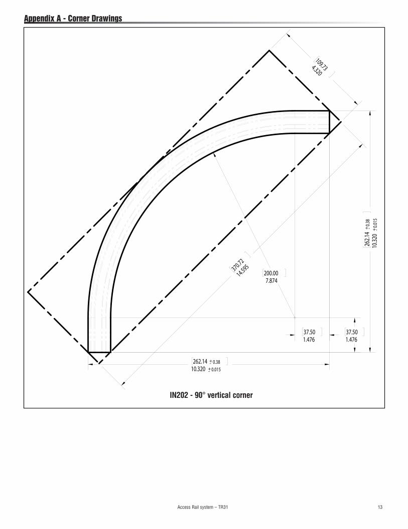
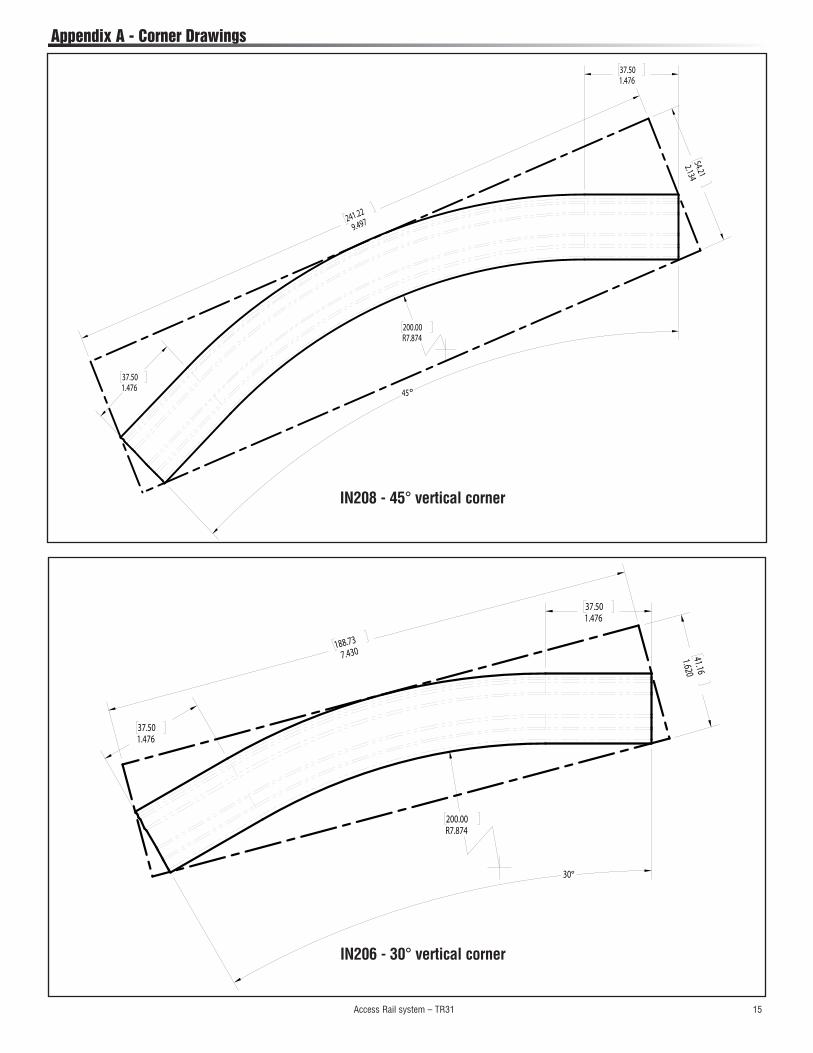
Note: See corner drawings in appendix A
Access Rail system – TR31 3
1) Applications
A PURPOSEThe rail and trolley system is designed for use as an adjustable anchorage point for prevention of man overboard and arrest on vessels such as pilot boats. Trolleys can travel around a radius as small as 200 mm (7 7/8"), allowing user to travel around corners without reconnecting to a different track.
2) System Requirements
C STANDARDS The system as outlined in this manual is designed to meet the requirements of:
EN795:2012, BS 7883:2005, MGN 410 MGN280 M including section 25.6.3.22.4 stating: An efficient, uninterrupted/continuous safety rail system for clip-on safety harnesses should be provided. The system should allow the harness traveler to move freely and without adjustment over the full length of the safety rail. The rail system, its attachment to the vessel structure and the clip-on safety harnesses should be designed, constructed, installed, tested, and maintained to appropriate personal protective equipment standards, to the satisfaction of the Certifying Authority.
Refer to individual countries and maritime standards for your region.
Harken equipment is designed for use with Harken approved components. Substitutions or replacements made with non-approved components may jeopardize compatibility of equipment and may affect the safety and reliability of the system.
Lanyards for connection to marine harness or life jacket, connectors (hooks, carabiners and D-rings) must be capable of supporting at least 22kN (5000 lb), in accordance with EN362.ww
WARNING! Consult Harken when using this equipment in combination with components or subsystems other than those described in this manual. Altering or intentionally misusing this equipment may cause the system to fail which can cause a fall which could result in severe injury or death.
B LIMITATIONSThe rail and trolley system is not intended for work positioning or movement under load.
Capacity: This system is designed for use by one person per 1.3 m (4.3') span, with a combined weight (clothing, tools etc.) of no more than 135 kg (297.68 lb). No more than one person per 1.3 m (4.3')span may be connected to the rail and trolley system at one time.
Training: This equipment must be installed and used by persons trained in its correct application and use.
The trolley is free rolling on the rail when unloaded. In the event of a fall, the wheels are designed to deform sufficiently so that the trolley contacts the rail and provides a "braking" effect.
Access Rail system – TR31 4
3) Installation
PLAN SYSTEMConsider all factors that will affect safety during use of this equipment.
Rail must be laid out and positioned as determined by a naval architect or other suitably qualified person.
Rail should run in a general horizontal direction. Where the system is being used to prevent MOB and there is no risk of falling from height, it is permissible to angle rail up or down to change to different deck levels. For example, a rail may curve downward to run along a stairway and continue at the lower deck at the rear of the wheelhouse. Use corner rails or order 3 m rail curved to required specifications.
Installer shall ensure suitability of base materials into which rail is fixed and that it is capable of sustaining test force as detailed in standard EN 795:2012.
The following publications give detailed information to ensure safe and legally compliant installation.
EN 795:2012 – Protection against falls from a height – Anchor devices – Requirements and Testing.
BS 7883:2005 – Code of practice for the design, selection, installation, use, and maintenance of anchor devices conforming to BS EN 795.
Avoid attaching system components where suspension and/or fall-arrest rope may come in contact with, or abrade against, unprotected sharp edges.
RAIL INSTALLATION
This TR31 Access Rail system should be installed only by a competent person or competent organization.
All rail listed in this manual is designed to use M10 flathead 316/A4 stainless steel fasteners. Metric flathead fasteners provide the best fit in track countersink hole angles. IMPORTANT! Rail fasteners are required every 1.3 m (4.3'). You must drill and countersink holes for M10 flathead fasteners. Any alternate attachment must be of sufficient structural strength to pass testing requirements as determined by installer. Attachment to vessel must be in accordance with MGN 280 (M). Harken does not recommend installing with aluminum fasteners. Always use threadlocking solution, Tef-Gel® paste or locknuts.
Upper deck
Lower deck
The rail can be mounted at various angles as shown below.
The shackle can be used on either side.
Ordering curved rail - IN209.3M.CLEAR rail can be bent in vertical or horizontal direction at Harken US or Harken UK. Provide template or radius information. Minimum bend radius 200 mm. See contact information on back cover.
Tef-Gel is a registered trademark of Ultra Safety Systems, Inc.
Access Rail system – TR31 5
It is the responsibility of the user and the purchaser of this equipment to assure that they are familiar with the instructions, trained in the correct care and use of this equipment, and are aware of the operating characteristics, application limits, and the consequences of its improper use.
PERSONAL FALL-ARREST EQUIPMENT
When using a hook with positive locking mechanism to connect to trolley shackle, ensure roll-out cannot occur. Roll-out occurs when interference between hook and mating connector causes hook gate to unintentionally open and release.
Self-locking snap hooks and locking carabiners should be used to reduce possibility of roll-out. Do not use hooks or connectors that will not completely close over attachment object.
WARNING! This product is part of a personal fall-arrest system. The user must follow the manufacturer’s instructions for each component of the system. These instructions must be provided to the user of this equipment. The user must read and understand these instructions before using this equipment. Manufacturer’s instructions must be followed for proper use and maintenance of this equipment. Alterations or misuse of this equipment, or failure to follow these instructions, may result in a fall or failure to prevent a fall leading to serious injury or death.
4) Use
5) Training
After a fall: Any equipment which has been subjected to the forces of arresting a fall must be removed from service immediately and destroyed by user or an authorized person.
Rescue: when using this equipment, the employer must have a rescue plan and the means at hand to implement it and communicate that plan to users, authorized persons, and rescuers.
To prevent trolley from rolling off rail, fasten 548 endstops to rail ends using specified stainless steel fasteners. All rail and endstop fasteners must be coated with an anti-corrosion compound such as Tef-Gel® paste.
Installer must ensure that instructions and limitations of use are clearly displayed close to system. This should include a statement that it is designed exclusively for use with personal protective equipment.
Note: A 3 mm (.12") gap is permissible to allow for vibration or thermal expansion.
. Tef-Gel is a registered trademark of Ultra Safety Systems, Inc.
3) Installation (continued)
Cutting track: If track is cut for joining to another track, drill 10.5 mm (.413") fastener holes with 90° countersink angle as shown at right. Locate hole center 25 mm (.984") from track end.
If track is cut for use as end of rail system, use the instructions provided with 548 endstop set.
22.4 mm (.882")
25 mm .984"
Drilling Track: Rail fasteners are required every 1.3 m (4.3').
Drill 10.5 mm (.413") fastener holes with 90° countersink angle as shown at right.
10.5 mm (.413")
2X Ø 10.5 mm (.413") through all Ø 22.4 mm (.882") x 90°
Access Rail system – TR31 6
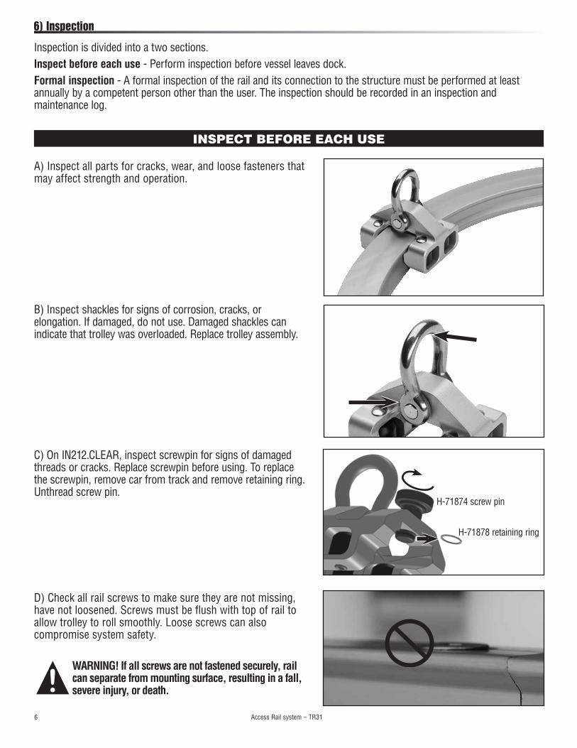
B) Inspect shackles for signs of corrosion, cracks, or elongation. If damaged, do not use. Damaged shackles can indicate that trolley was overloaded. Replace trolley assembly.
WARNING! If all screws are not fastened securely, rail can separate from mounting surface, resulting in a fall, severe injury, or death.
B
B
D) Check all rail screws to make sure they are not missing, have not loosened. Screws must be flush with top of rail to allow trolley to roll smoothly. Loose screws can also compromise system safety.
C) On IN212.CLEAR, inspect screwpin for signs of damaged threads or cracks. Replace screwpin before using. To replace the screwpin, remove car from track and remove retaining ring. Unthread screw pin.
6) Inspection
INSPECT BEFORE EACH USE
A) Inspect all parts for cracks, wear, and loose fasteners that may affect strength and operation.
Inspection is divided into a two sections. Inspect before each use - Perform inspection before vessel leaves dock. Formal inspection - A formal inspection of the rail and its connection to the structure must be performed at least annually by a competent person other than the user. The inspection should be recorded in an inspection and maintenance log.
H-71878 retaining ring
H-71874 screw pin
Access Rail system – TR31 7
Remove and inspect trolley for damage, corrosion, strength, and operation. Inspect pinstop on IN210 CLEAR trolley for cracks or wear that may affect locking strength and operation.
6) Formal Inspection
A formal inspection of rail for cracks, deformation, corrosion or wear and its connection to structure must be performed annually by a trained person. Record inspection results in a log. See page 9.
E) Inspect endstop screws to make sure they have not loosened and are flush with top of endstop.
WARNING! If endstop screws loosen, trolley can roll off end of rail, resulting in a fall, severe injury, or death.
6) Inspection (continued)
Inspect rail for cracks, deformation, or wear.
Inspect attaching fasteners for loosening, damage, or corrosion that may affect strength.
See Inspection “BEFORE EACH USE”, pages 6 and 7.
SERVICEIf inspection reveals an unsafe or defective condition, remove item from service and destroy it.
If in doubt, please contact manufacturer for further advice.
Access Rail system – TR31 8
Flush trolley frequently by squirting a detergent/water solution into top of rollers accessed through openings on the side of trolley. Roll trolley back and forth to distribute evenly. Flush rollers with fresh water. When dry, use a single drop of McLube® OneDrop™ conditioner placed in the top of the roller as shown at right.
IMPORTANT! Do not grease parts. This will cause rollers to skid instead of roll. Only clean as directed above.
7) Maintenance
Cleaning and flushing points
Roll trolley back and forth
McLube is a registered trademark of McGee Industries, Inc.OneDrop is a trademark of McLube, a division of McGee Industries, Inc.
Clean tracks with detergent and water, using a rag to wipe recessed section of track. Flush with fresh water.
Year of Manufacture Purchase Date Date First Put Into Use
Other important information (i.e. document number):
A record must be kept for each component, subsystem and system, with the following details (see example record log below).
It is the responsibility of the user organization to provide the record and to enter the details required into the record.
EXAMINATION/REPAIR HISTORY
Date Reason for entry (periodic exam or repair)
Defect notes, repairs carried out, and other important information
Name and signature of competent person
Date of next periodic examination
9) Records
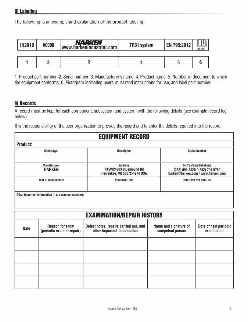
The following is an example and explanation of the product labeling:
1. Product part number; 2. Serial number; 3. Manufacturer’s name; 4. Product name; 5. Number of document to which the equipment conforms; 6. Pictogram indicating users must read instructions for use, and label part number.
IN2010 A0000 www.harkenindustrial.com TR31 system EN 795:2012xxxx
INTRODUCTIONThe following is the good faith interpretation by Harken of the standards that we understand are the current methods that will meet the requirements of many test procedures to assure a safely installed Harken TR31 Tight Radius system. Harken is not responsible for any future changes, alternate interpretations, or other requirements imposed by inspection officials. Harken does not accept any responsibility for the consequences of failed installations, including but not limited to, personal injuries, costs, any related damages, or from failed alternative installation methods. The installer is directed to carefully consider BACKGROUND.
The Harken TR31 system is fully tested and certified under EN 795:2012 as a fall-arrest anchor device. However, we have had a number of requests to approve alternative methods of fastening due to different construction and building techniques.
Regrettably, it is simply not possible for us to approve all these alternatives without detailed engineering, testing, and surveying of every individual case.
Therefore, the purpose of this guidance is to illustrate how alternative methods of attachment can be considered by the installer and considered as suitable.
To be 100% explicit, this guidance is regarding the installation of the product and has nothing to do with the product itself.
BACKGROUNDWe have researched the MCA documentation and BS 7883:2005 PPE Anchor Device Testing. From this we can draw two critical principles:
A) Any safety equipment or lifting device must have its installation inspected and surveyed as per standard industry practice. Likewise, periodic inspection is necessary to ensure nothing has deteriorated due to age, wear or corrosion. There are well established systems and protocols in place to ensure this is done. This is nothing special or unique to the Harken TR31 Tight Radius system.
B) As per the MCA code of practice (Chapter 21.6.1), the Installer has the full responsibility for a proper, safe installation that is tested to meet all relevant standards. Normally this would be verified by an independent safety surveyor.
REGARDING BS 7883:2005This Code of Practice details the maintenance and testing regime of EN 795:2012 anchor devices for fall protection. It recommends an initial sample (3no.) proof test of 12kN (1200 kgs) for three (3) minutes if the installation is into a base material that the installer has no information on, or has never installed into before. If the samples tested pass, the rest of the anchor points shall be tested to 6kN (600 kgs) for 15 seconds.
If the anchor device is only used for fall protection, the device should be thoroughly examined and tested annually to 6kN (600 kgs) for 15 seconds. If the device is used for suspending personnel or rope access, the device should be thoroughly examined and tested every six (6) months at a minimum.
CONCLUSION BS 7883:2005 standard gives a good reference point to offer guidance on testing of any rail installation, new or retrofit. However, at the time of publication, there were on-going discussions with the relevant authorities to reduce the proof-test load to 6kN (600 kgs) to reflect the practical difficulties of achieving 12kN (1200 kgs) pull especially on pulpit/ tubular frame structures.
Appendix B
Access Rail system – TR31 17
Please refer to your surveyor for final approval.
Our interpretation in practical application is:
1. PROOF TESTING1.1 The test objective is for the installer to prove their individual installation methodology for each type of base material/fastener type, or where working with unknown factors.
1.2 The surveyor will have to approve the individual test regime and be satisfied it was done correctly. In practice this normally means overseeing the test.
1.3 For new builds or for identical constructions, the proof test can be done on representative sample pieces. These should be long enough to hold a trolley in normal configuration plus the endstops. This should replicate the longest unsupported span of rail required by the installation.
1.4 This proof test can be applied to installations if the construction is identical and as long as it is properly documented.
1.5 In the case of retrofits where the construction is not necessarily known (due to modifications, corrosion, or aging), the proof testing will have to be done in situ.
1.6 If done in place, then we recommend testing in highest risk locations such as where personnel gain access to the system, or at the ends of the rails.
1.7 Subject to surveyor approval, the proof test procedure would be:
Note: This is a static test. There is no drop load. The trolley is not expected to move under these conditions.
i. Attach a water bag to a single trolley.
ii. Fill to achieve a load of 6kN (600 kg).
iii. Hold for three (3) minutes without deformation – paying particular to rail/fastener stability and the supporting structure.
iv. Drain/unload water bag, move and repeat in two (2) other locations (or sample pieces).
v. The system should remain functional.
2. INSTALLATION TESTING:
2.1 This test objective is to ensure that the system has been installed correctly in practice and remains sound as it ages.
2.2 We recommend that each rail is tested in at least three (3) locations; typically at both ends, at any rail joint, or in the middle.
2.3 Again subject to surveyor approval, each rail should be tested upon installation:
i. Attach a water bag to a single trolley.
ii. Fill to achieve a load of 6kN (600 kg).
iii. Test for 15 seconds per location.
iv. Repeat as necessary for each separate rail.
2.4 Normal safety equipment operations requires testing post-installation and then six (6) monthly routine inspections with 12 monthly testings.
2.5 Further testing and inspection of the TR31 system should be incorporated into standard operating practices and into the safety records.
Appendix B
Access Rail system – TR31 18
Appendix B
3.0 Documentation to be supplied after installation:
i. The installation documentation provides evidence to the end uses, and that the installation has been carried out properly.
ii. The documentation should be handed over to the user and kept on hand for subsequent examinations of the device.
iii. The documentation should contain at least:
• Address and location of installation
• Name and address of installation company
• Name of the person in charge of the installation
• Product identification
• Fixing device
• Schematic installation plan
• A declaration by the installer that it is:
Installed in accordance with manufacturer's instructions;
Carried out in accordance to plan;
Fixed as specified;
Commissioned in accordance with manufacturer's instructions;
Supplied with photographic information/documentation.
1/09/10 Andrew Ash-Vie
Managing Director, Harken UK Ltd
Updated in line with EN 795:2012 11/24/2015
Access Rail system – TR31 19
Access Rail system – TR31 20 Printed in USA 5802 05-16
Worldwide Limited Warranty
COVERAGE. HARKEN® warrants that each HARKEN product, when properly used and maintained, will be free from defects in material and workmanship from the date of receipt of the product by the final customer.
THE LIMITED WARRANTY. This limited warranty applies to all Harken products purchased. The sole and exclusive remedy under this LIMITED WARRANTY for original defects in materials or workmanship of a HARKEN product shall be the repair or replacement,in HARKEN’s sole discretion, of the defective part or component, in accordance with the terms of this warranty.
WARRANTOR. For products originally sold in the Unites States, the limited warranty for the products is supplied by HARKEN, INC. For products originally sold in the European Union, the limited warranty for the products is supplied by the dealer who sold the product through the Harken Distributors in that country. For products originally sold in the rest of the World, the limited warranty for the products is supplied directly by the Harken Distributors in that country. When“HARKEN” is mentioned throughout this limited warranty, it refers to the entity as defined in this paragraph.
OWNER – NON-TRANSFERABLE WARRANTY. This warranty is made by HARKEN with the original purchaser of the product and does not extend to any third parties. The rights of the original purchaser under this warranty may not be assigned or otherwise transferred to any third party.
WARRANTY TERM. The LIMITED WARRANTY covers any original defects in material or workmanship manifested within 12 months of the date of receipt of the product by the final customer.
NOT COVERED. The LIMITED WARRANTY does not apply to, nor shall HARKEN have any liability or responsibility for, damages or expenses relating to defects caused by misuse, abuse, failure to install, use, maintain or store the HARKEN product as specified in the warranty booklet, service booklet, manuals, catalogue or other literature available from HARKEN.
The LIMITED WARRANTY does not apply to, and neither shall HARKEN have any liability or responsibility in respect to, damages or expenses relating to:
• Defects in material or workmanship that did not exist when the product was first delivered;
• defects in material or workmanship that are manifested outside the warranty period;
• defects which are not reported to HARKEN within sixty (60) days of discovery;
• a product that has been altered or modified from factory specifications;
• damage or deterioration of cosmetic surface finishes, including cracking, crazing, discoloration or fading;
• accidents, misuse, abuse, abnormal use, improper use, lack of reasonable or proper maintenance or storage;
• installation, service or repairs improperly performed or replacement parts or accessories not conforming to HARKEN’s specifications;
• use exceeding the recommended and permitted limits or loads of the product and/or the product on which the product is installed;
• normal wear or deterioration occasioned by the use of the product or its exposure to the elements;
• ropes, lines, buckles and webbing;
• loss of time, loss of use, inconvenience, travel expense, costs related to procuring any substitute product, transportation costs, any incidental or consequential damages arising out of the non-use of the product, or compensation for inconvenience or loss of use while the product is being repaired or otherwise not available, or other matters not specifically covered hereunder;
• the costs to remove, disassemble or reinstall the product;
• removal, storage and replacing of the product on which the product has been installed, even where this is necessary to carry out the warranty service.
The LIMITED WARRANTY does not cover, nor shall HARKEN have any liability or responsibility in respect of, damages or expenses relating to, the following products and/or components: