Tracer® TU Service Tool User Guide March 2020 BAS-SVU047B-EN SAFETY WARNING Only qualified personnel should install and service the equipment. The installation, starting up, and servicing of heating, ventilating, and air-conditioning equipment can be hazardous and requires specific knowledge and training. Improperly installed, adjusted or altered equipment by an unqualified person could result in death or serious injury. When working on the equipment, observe all precautions in the literature and on the tags, stickers, and labels that are attached to the equipment.
Transcript
Tracer® TU Service Tool
User Guide
March 2020 BAS-SVU047B-EN
SAFETY WARNINGOnly qualified personnel should install and service the equipment. The installation, starting up, and servicing of heating, ventilating, and air-conditioning equipment can be hazardous and requires specific knowledge and training. Improperly installed, adjusted or altered equipment by an unqualified person could result in death or serious injury. When working on the equipment, observe all precautions in the literature and on the tags, stickers, and labels that are attached to the equipment.
IntroductionThis Getting Started Guide presents an overview of the Tracer TU features and capabilities thatsupport your work. The early sections include:
• A summary of the product capabilities
• An explanation of the various device connection options
• Guidance for the first time user on how to start a Tracer TU session
• A description of the main user interface features
The remaining sections provide quick tours through the main versions of the product, Tracer TUfor Chillers and Tracer TU for Programmable Controllers. It also briefly describes the threeclosely integrated applications used with the main Tracer TU application:
• The Tracer Graphical Programming (TGP2) Editor
• The Tracer Graphics Editor (TGE)
• The Tracer SC User Interface.
This guide is intended to complement the two main Online Help systems, the Tracer TU Help forChillers and the Tracer TU Help for Programmable Controllers.
Warnings, Cautions, and NoticesSafety advisories appear throughout this manual as required. Your personal safety and theproper operation of this machine depend upon the strict observance of these precautions.
The three types of advisories are defined as follows:
WARNINGIndicates a potentially hazardous situation which, if not avoided, could result indeath or serious injury.
CAUTIONIndicates a potentially hazardous situation which, if not avoided, could result inminor or moderate injury. It could also be used to alert against unsafe practices.
NOTICEIndicates a situation that could result in equipment or property-damage onlyaccidents.
CopyrightThis document and the information in it are the property of Trane, and may not be used orreproduced in whole or in part without written permission. Trane reserves the right to revise thispublication at any time, and to make changes to its content without obligation to notify anyperson of such revision or change.
TrademarksAll trademarks referenced in this document are the trademarks of their respective owners.
Appendix A. Tracer TU Installation and Connection Error Conditions . . . . . . . . A–1
TTaabbllee ooff CCoonntteennttss
8 BAS-SVU047B-EN
Tracer TU Service Tool OverviewThe Tracer TU service tool is available in three main product versions, which are available inseveral user licenses with various feature sets.
Tracer TU for Chillers(Available in Pro – Chiller View, Professional, and Unlimited Licenses)
This version continues to provide full support for the UC800 and CenTraVac™ chillers as well asselected Series R™ chillers. It includes chiller configuration, LLID binding, status andperformance monitoring, diagnostics, trending, reporting, and backup and restore utilities.
NNoottee:: The Controls, and Advantage software licenses do not include Tracer TU for Chillers.Therefore, the Tracer TU for Chillers information included in this guide does not apply tothese licenses.
Tracer TU for Programmable Controllers(Available in Pro – Controls, Professional, Advantage, and Unlimited licenses)
This version of Tracer TU provides a large feature set including point, device, and networkmonitoring, online and offline controller configuration, offsite facility configuration, groupoverrides, custom views of network devices, data logging, reporting, wireless network creationand maintenance, and backup and restore utilities. This version provides support for thefollowing Trane products:
• Tracer® Ensemble™
• Tracer® SC+ System Controller and the Tracer® SC System Controller
• Tracer® UC210 controller
• Tracer® UC400 controller
• Tracer® UC600 controller
• BACnet® Communication Interface for Chiller (BCI-C)
• BACnet® Communication Interface for IntelliPak (BCI-I)
• BACnet® Communication Interface for ReliaTel (BCI-R)
It also includes the following features and applications:
• The File Transfer Utlity
• The Backup Utility
• Offline Controller Configuration
• Offsite Facility Definition
• Air and Water Balancing Tools
• The Tracer Graphical Programming (TGP2) Editor
• The Tracer Graphics Editor (TGE)
• Access to the Tracer SC User Interface
Tracer TU Complete(Available with Professional and Unlimited Licenses)
The Tracer TU Complete version of the Tracer TU service tool provides the two main versions ofthe software in one package. The version of Tracer TU you see depends on the controller towhich you are connected. Tracer TU for Chillers appears when you connect to a UC800. TracerTU for Programmable Controllers version appears when you connect to all other programmableTrane BACnet controllers.
BAS-SVU047B-EN 9
Laptop RequirementsYour laptop must meet the following hardware and software requirements:
• 4 GB RAM
• 1024 x 768 screen resolution
• Ethernet 10/100 LAN card
• An available USB 2.0 port
• Windows 7 Service Pack 1 Enterprise or Professional (32-bit or 64-bit) or Windows 10Anniversary Edition operating system (32–bit or 64–bit)
• Microsoft .NET Framework 4.8 or later (auto-installed if not present)
• Microsoft Visual C++ Redistributable for Visual Studio 2015, 2017, and 2019 (v142) (auto-installed as required for TGP2 and the legacy Trane USB driver)
NNootteess::
• Tracer TU is designed and validated for this minimum laptop configuration. Anyvariation from this configuration may have different results. Therefore, support forTracer TU is limited to only those laptops with at least the configuration previouslyspecified.
• In addition, for optimal Tracer TU performance the following features arerecommended:
– 8 GB RAM
– A 7200 RPM hard disk drive or a solid state drive
• To view the Tracer TU Getting Started Guide (pdf format), download the AdobeAcrobat Reader DC from https://get.adobe.com/reader/.
Tracer TU for Programmable Controllers Features and CapabilitiesThis version of Tracer TU for Programmable Controllers provides the following features andcapabilities:
Multiple connection options for UC210, UC400, UC600, and System Controllers• Connect to UC210s, UC400s, UC600s, and System Controllers directly via USB cable,
indirectly via System Controller pass-through using an Ethernet cable or LAN access, orthrough a zone sensor or a wireless network using the Tracer TU Adapter (Wired/ Wireless).(See “Access to Devices on Wireless Networks,” p. 55).
NNoottee:: When connecting to a System Controller through a network, Tracer TU uses an HTTPconnection (Port 80) by default. If you want to use a secure connection (HTTPS), selectPort 443 or an alternate port number designated by the site for that purpose. Bear inmind that using a secure connection will slow Tracer TU performance.
• Use BACnet Discovery to view and access all devices on an IP network including additionalSystem Controller and their links.
NNoottee:: BACnet Discovery requires V8.6 or higher firmware to be installed on all devices.
• Connect to a Trane BACnet device on a single MS/TP link and then from that connectionpoint, discover, access, and perform service on other Trane BACnet devices on that link. (See“ Single Link Access,” p. 69 for additional information, specific usage rules, andconsiderations.)
NNoottee:: A UC800 with firmware level 5.24 or higher can be discovered and serve as a SingleLink Access connection point. However, access to the UC800 is not allowed.
Wireless Network Management• Assess network health by viewing a Network Summary Report and a graphical mapping of a
network that indicates the strength of communication links and the number of hops from thecoordinator to each member device.
• Use Wireless menu options to form networks, add or remove devices, disband a network, andview information about the WCIs.
• Associate up to six wireless sensors with one controller to obtain an average temperaturewithout TGP2 programming.
Equipment Status• View controller status.
• View the status of points and alarms.
Point Configuration and Overrides• Create and edit points in a controller configuration file (UCxxxConfig) offline or online while
connected to a device.
• Use the Facility View to perform a group override of all air valves and water valves for theentire communication link or for selected devices. Calibrate air valves on a linksimultaneously.
• Use right-click menus to create, edit, delete, and override points or put points out of service.You can also access point information on the Status Utility Analog, Binary, and Multistatescreens.
• Use the Command Compare feature to determine if a selected point is performing asintended by monitoring its effect on a related point. (See “Using Command Compare,” p. 43and "Overriding, Comparing, and Changing the Service Status of Points" in the Tracer TUHelp for Programmable Controllers for more information.
Supported Equipment Types• Configure and commission VAV boxes, blower coils, fan coils, unit ventilators, and variable-
• Edit points and programs in standard Trane factory blower coil, fan coil, and unit ventconfigurations to suit job requirements. (See “Factory Equipment Configurations You CanModify (UC210 and UC400),” p. 57.)
• Perform step tests for VS-WSHPs and BCI-Rs.
• View BCI-R, BCI-C, and BCI-I points and status information. Set up alarms and data logs.
Trending Data Logs and Live Data• View and trend data logs retrieved from a UC210, UC400, or UC600.
• Configure and start a session log to capture and graph real time data on the UC600.
• Create and save graph templates for reuse.
• Capture data while a data log is running
NNoottee:: Session logging is not available when using System Controller pass-through.
Controller Settings• Specify the units used to display controller data in Tracer TU and the units used on the
controller.
• Specify the rotary dial setting or software device ID and baud rate.
• Set up and discover XM30, XM32, XM70, and XM90 expansion modules.
• Setup a controller to use multiple wireless sensors.
• Configure notification classes.
• Configure UC600s for enhanced communication including DHCP or static IP addressing, HTTPor HTTPS (secure) communication, browser access to TD7 Display content, BBMD capability,and a choice of BACnet IP, BACnet Zigbee, or BACnet MS/TP communication.
Notification Class ConfigurationYou can create, configure, and edit BACnet controller notification classes either (1) online or (2)offline within a Controller Configuration using the Notification Class box on the ControllerSettings screen. You can also add, edit, or delete event recipients for notification classes.
Offsite Facility DefinitionsA Facility Definition is an entire pre-configured and pre-programmed facility that includes twomain parts:
• An offline Facility Configuration, which is created in Tracer TU
• All required System Controller database configuration and programming
Creating a Facility Definition allows you the freedom to complete much of the device and SystemController database configuration and programming work at your office before you arrive at thejob site. When both parts of the Facility Definition are complete, you can save them to a portablestorage device as two files: (1) A Facility Configuration Export file (*.zip) and (2) a SystemController backup file (*.zip). These two parts are then merged at the job site after you restore theSystem Controller backup file to the System Controller and import the Facility ConfigurationExport File into Tracer TU. (See “Offline Facility Configurations Used to Build Offsite FacilityDefinitions,” p. 58 for additional information.
CSET File ImportImport a CSET file into Tracer TU. This import capability reduces the cost associated with reworkand errors when creating a Facility Configuration from a CSET file. You can import the CSET fileand edit the resulting Facility Configuration file as necessary.
NNoottee:: It may be necessary to assign Controller Configurations or Equipment Templates tocustom devices or certain non-Trane, Legacy, or LonTalk devices not recognized by theSystem Controller.
Multiple ways to view devices, points, and properties• The Facility View features a set of standard "views" made up of different collections of points.
The collection of points in each view supports a specific function (for example, VAV setup).
• Access and view Modbus, LonTalk, Trane Legacy, and non-Trane BACnet device points onspecial Unit Summary and Unit Status screens through a System Controller connection.Toggle between some System Controller (converted) values and their correspondingcontroller (communicated) values.
Two Tracer TU SessionsOpen a second Tracer TU session (instance) from within a first Tracer TU session and eitherconnect to a UC400/210/600 to perform online tasks or perform offline tasks. Each Tracer TUsession runs independently of the other.
• Access the same controller in two sessions using a USB connection.
• Work in a System Controller and a device on its networks simultaneously.
• Use a wired/wireless connection through the Tracer TU Adapter to launch one or both TracerTU sessions.
Report GenerationYou can generate three types of reports in Comma Separated Value (.csv) format:
• Point Summary—Contains properties of all points in the controllers selected.
• Auto Commissioning—Covers a set of VAV devices from the Auto Commissioning dialogbox.
• Custom Facility—Based on any standard or custom view on the Facility View (a predefinedset of points for a group of devices).
Controller Configurations and Equipment TemplatesCreate, save, and edit a complete controller configuration that includes a point configuration,data logs, TGP2 programs (.tgp2 and .bc files), and internal template information. Use the normalTracer TU utility screens to include points, TGP2 programs, data logs, alarms, standard orcustom graphics, TD7 Display graphics, TD7 reports, and UC600 schedules. During editing, theinternal template information is kept up to date. You can then download the ControllerConfiguration to similar devices without overwriting identifying information on the targetdevices. You can also assign them to offline controllers in a Facility Configuration. (See“Controller Configurations,” p. 57.)
Equipment Templates are assigned primarily to some Legacy Trane UCMs, non-Trane BACnetdevices, and LON devices. They provide only the interface used by the System Controller toinstall and control these devices and do not contain any configuration information. You canconvert System Controller Equipment Templates to Tracer TU Equipment Templates, or createthem in Tracer TU for use in a Facility Configuration.
Tracer UC600 Operator Display User InterfaceYou can access and work with the UC600 Operator Display User Interface screens directly withinTracer TU when connected to a UC600 with or without a TD7 Display.
UC600 Tracer™ TD7 Display• Enable the Tracer TD7 display by
– Configuring three custom reports for the Tracer™ TD7 Display. (See “UC600 CustomReports” in this table.)
– Creating up to three schedules on the UC600. (See “UC600 Scheduling” in this table.)– Setting display preferences for the Tracer TD7 display.
• Limit Tracer TD7 access to a set of user-id and PIN combinations defined on the Securityscreen of the Tracer TU Controller Settings Utility.
UC600 Custom ReportsConfigure three custom reports for the Tracer™ TD7 Display that can each include real timevalues for up to 27 data points. You can then view these reports either on the Tracer TD7 andfrom within Tracer TU. (See “Custom Reports for Tracer™ TD7 Display (UC600),” p. 54.)
UC600 SchedulingCreate three schedules on the UC600 with advanced schedule set up and maintenance screens.You can also view and work in the actual TD7 Display screens through Tracer TU with or withouta TD7 Display. (See “UC600 Scheduling Screen,” p. 53.)
UC600 Event LogView the UC600 Event Log on the Alarms screen. You can clear the Event Log by clicking theClear Event Log button located below the log.
Backup and RestoreUse the Backup Utility to back up all files and configuration information on one or morecontrollers to your designated backup location. The backup operation includes compiled TGP2programs, configuration parameters, and the points.xml file. You can use the File Transfer Utilityto load a backup file containing configuration data and programs on field programmablecontrollers or to restore a controller. The File Transfer Utility and the Backup Utility display adetailed Error Report containing an error message for each affected device when a file transfer tothe System Controller or a backup operation fails. (See “File Transfer and Backup ErrorMessages” in the Online Help.)
NNoottee:: File backup and transfer operations on the UC800 and BCI-C require a direct USBconnection for reasons of human and machine safety.
Air and Water BalancingYou can use Tracer TU to perform several air and water balancing tasks:
• Calibrate one or more VAV air valves to maximum and minimum flow so you can takephysical air flow measurements. Tracer TU uses your measured values to calculate the AirFlow Gain and Air Flow Measurement Offset values for both maximum and minimum airflow. You can calibrate the air valves of multiple VAV units in the Facility View. You can alsocalibrate the hot deck air valve for VAVs configured as dual duct.
• Auto-commission single and dual duct VAV boxes.
• Override one or more air valves, fans, or water valves on VAV boxes, fan coils, blower coils,unit ventilators, and water source heat pumps.
Related ApplicationsLaunch related applications from within Tracer TU:
• The System Controller software (a Web application)
• The TGP2 Editor
• The Tracer Graphics Editor (TGE)
Upload/Download Files (File Transfer/File Backup)• Upload programs to Tracer TU for editing.
• Perform a mass download of Controller Configurations, Backup files, programs, and firmwareto one or more devices (System Controllers, UC210s, UC400s, UC600s, Air-Fi™WirelessCommunications Interfaces (WCI), and Air-Fi™Wireless Communications Sensors (WCS).)
The File Transfer Utility and the Backup Utility display a detailed Error Report containing anerror message for each affected device when a file transfer to the System Controller or abackup operation fails. (See “File Transfer and Backup Error Messages” in the Online Help.)
• Make incremental changes to controller configurations and save only those changes withouthaving all standard points return to factory defaults. (Requires a sealed factory configurationand system build 2.65 or higher.)
NNoottee:: File transfer operations on the UC800 and BCI-C require a direct USB connection forreasons of human and machine safety.
Tracer TU for Chillers Features and CapabilitiesNNoottee:: The Pro-Controls and Advantage software licenses do not include Tracer TU for Chillers.
Therefore, the Tracer TU for Chillers information included in the following table does notapply to these licenses.
The Tracer™ TU for Chillers provides the necessary setup, configuration, and monitoringcapabilities used with the Tracer AdaptiView™ control to service Trane CenTraVac™ chillers(models CVHE, CVHF, CVHG, CVHH, CVHL, and CVHS), CenTraVac Duplex chillers (models CDHF,CDHG, or CDHH), AdaptiView Panel Upgrades (CVRE), GVAF, Ipack, and Series R™ chillers(models RTAE, RTAF, RTHA-B, RTHC, RTHD and RTWF). Tracer TU for Chillers capabilities arelisted in this subsection.
Connect directly to UC800 via USB• Connect to and read the settings from a Tracer AdaptiView controller (UC800).
• Connect to a UC800 on a single MS/TP link and then from that connection point, discover,access, and perform service on other Trane BACnet devices on that same link. (See “ SingleLink Access,” p. 69 for additional information, specific usage rules, and considerations.)
NNoottee:: This capability does not apply to UC800s with firmware lower than 5.24 or to use withTracer TU for Chillers (Chiller-Only) Edition.
Chiller StatusMonitor chiller and controller status including line side data that indicates chiller powerconsumption.
Chiller Configuration• Create a new chiller configuration.
• Make changes to chiller configuration settings.
• Save changed setpoints and configurations to the controller.
• Save chiller configurations to your hard drive and then reuse the configurations on multiplechiller units.
OverridesOverride selected chiller outputs. In addition, the Manual Overrides screens provide one locationwhere you can perform key manual overrides for CTV, CTVD, RTAE, RTAF, RTHA-B, RTHC, andRTHD chillers. You can view the values of various monitor points for several of the suppliedoverride points.
Alarms and DiagnosticsCheck for and respond to alarms.
Data RecordersCreate up to three custom data recorder files to track specific points over time.
Two Tracer TU SessionsOpen a second Tracer TU session (instance) from within a first Tracer TU session and connect toa UC400, UC210, UC600, the same UC800, or a controller configuration to perform online oroffline tasks. You can also connect to a second UC800 using System Controller pass-through for
viewing and reporting purposes. (Only one session can use a USB connection when connectingto two different controllers.) Each Tracer TU session runs independently of the other.
NNoottee:: This feature is for internal Trane use only.
ReportingProduce XML-based ASHRAE Chiller and Event Log reports, which are rendered as Web pagesand can also be saved in PDF format.
Chiller firmware wizardTwo levels of firmware are included in the product installation file for each chiller model.
You can obtain additional levels of chiller firmware using a firmware setup wizard, which isavailable on the Tracer TU installation flash drive. The new firmware setup wizard allows you toview and select the specific firmware levels you need.
Backup and RestoreBack up and restore UC800 configuration files.
Installing Tracer TUThis section explains how to obtain the Tracer TU installation file and install your licensedversion of the software on your PC.
Contact your local Trane sales office to order Tracer TU.
Special Installation Requirement: .NET Framework 4.7An Internet connection is required during Tracer TU V10.0 installation to enable installation ofMicrosoft .NET Framework 4.7. The installation procedure you encounter depends on the level ofthe Windows operating system on your PC.
• Windows 7 SP1
To run .NET Framework 4.7 on Windows 7 SP1 you must first install the DD33DDCCoommppiilleerr__4477..ddllllfile. If you try to install the Microsoft .NET Framework 4.7 on a computer that runs Windows 7Service Pack 1 (SP1), the setup is blocked and cannot continue. You will see the followingmessage box:
Click the uuppddaattee link in the message box to download the required dll. You can also findinformation at\https://www.microsoft.com/en-us/download/details.aspx?id=55170.
• Windows 10
The Windows 10 Anniversary Update or higher is required for this upgrade. If you are runninga lower version of Windows 10, first install the Anniversary Update. See\https://www.microsoft.com/en-us/download/details.aspx?id=55170.
Installation ProcedureWhen you have obtained the Tracer TU installation USB flash drive, complete the following stepsto install the software.
NNootteess::
• The USB flash drive should only be used to install Tracer TU.
• Installing Tracer TU requires Administrator account privileges. Before you attempt toinstall the software, you should verify that the installing user-id has these privileges.See your software administrator for assistance.
• The installing user-id is the only user-id that can access and operate Tracer TU, unlessyou complete an additional procedure. (See “Establishing Access to Tracer TU forAlternate Users,” p. 19).
1. Place the installation flash drive in a USB port.
The installation should start automatically. If the installation does not start automatically,perform the following steps:
a. Click SSttaarrtt in the bottom left corner of your screen.
b. Click RRuunn.
BAS-SVU047B-EN 17
c. Browse to the location of the installation file ((TTrraacceerr TTUU SSeettuupp..eexxee)) and click OOppeenn.
d. Click OOKK on the Run dialog box.
A Welcome dialog box appears.
2. Click NNeexxtt.
3. Click II aacccceepptt .. .. .. to accept the License Agreement after reviewing it.
4. Click NNeexxtt to accept the default installation location (C:\Program Files\Trane\Tracer TU).
(You can click CChhaannggee to specify an alternate location before clicking Next.)
5. Select AAnnyyoonnee wwhhoo uusseess tthhiiss ccoommppuutteerr or OOnnllyy ffoorr mmee on the User Profile dialog box.
6. Discontinue any connection between your PC and a Trane controller before starting theinstallation.
7. Click IInnssttaallll on the Ready to Install Tracer TU dialog box.
8. Click OOKK if you see a message box indicating that the Microsoft .NET run-time files are out ofdate. This software is required to run Tracer TU.
NNoottee:: Extra steps may be required if you are installing Tracer TU on a Windows 7 or highermachine and Microsoft .NET 4.7 must also be installed as part of the installation. When .NET 4.7 is finished installing, you are prompted to restart your machine. After therestart, you must start the installation once again (by clicking the Tracer TU Setup.exefile) to resume and complete product installation. You may then be prompted to installan additional Redistributable file as well.
9. Click CCoonnttiinnuuee AAnnyywwaayy if the dialog box warning you that the software has not passedWindows Logo testing appears.
10. Click FFiinniisshh to complete the installation process.
Special Situation: Stopping the Tracer TU ServiceIn rare circumstances, when you are upgrading Tracer TU from an earlier release, you may seethe following message:
The message box includes the "Retry" and "Cancel" options.
If you encounter this message, perform the following steps:
1. Open the Windows Task Manager by pressing CCttrrll--AAlltt--DDeelleettee and then clicking the TTaasskkMMaannaaggeerr button.
2. Go to the PPrroocceessss tab.
3. Find and select EEvvooUUSSBB..eexxee.
4. Click EEnndd PPrroocceessss.
5. Return to the message dialog box and click RReettrryy.
The Tracer TU upgrade installation will continue.
IInnssttaalllliinngg TTrraacceerr TTUU
18 BAS-SVU047B-EN
Results of the InstallationThe installation routine places all system files in different locations depending on whether a 32–bit system or a 64–bit system is installed.
• For Windows 7 or 10 64-bit systems, the Tracer TU system files are placed under the ProgramFiles (x86) folder (C:\Program Files (x86)\Trane\Tracer TU)
• For Windows 7 or 10 32-bit systems, the Tracer TU system files are placed under the ProgramFiles folder (C:\ProgramFiles\Trane\TracerTU).
The installation also places three icons on your desktop (Tracer TU, Tracer SC via USB, and TraneController Via USB). A Tracer TU program item is also added to the Programs list on the StartMenu.
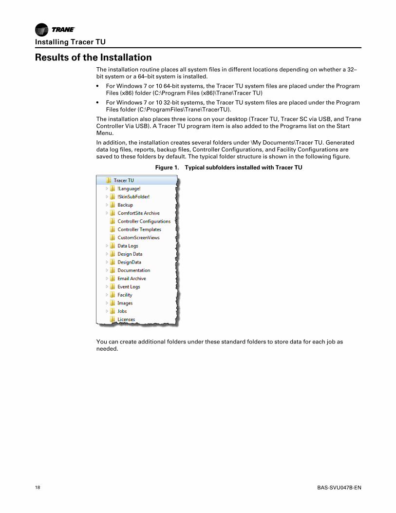
In addition, the installation creates several folders under \My Documents\Tracer TU. Generateddata log files, reports, backup files, Controller Configurations, and Facility Configurations aresaved to these folders by default. The typical folder structure is shown in the following figure.
Figure 1. Typical subfolders installed with Tracer TU
You can create additional folders under these standard folders to store data for each job asneeded.
IInnssttaalllliinngg TTrraacceerr TTUU
BAS-SVU047B-EN 19
Obtaining a Product LicenseLicensing and Registering Tracer TU
Tracer TU is a licensed product. You must obtain a license for each PC on which Tracer TU isinstalled. In addition, your Tracer TU license will be valid for a set period. As the expiration dateapproaches, you will be notified each time you start Tracer TU. When your license expires, TracerTU will no longer be operable. You can only launch the Tracer TU Balancing Tool at that time. Ifyou have not used Tracer TU during the time when the expiration warnings would have beendisplayed, you are given a two-week grace period during which you can update your license.
Complete the following procedure on each PC to obtain a product license and to register yoursoftware:
1. Click the TTrraacceerr TTUU icon on your desktop to start Tracer TU.
2. Click AAccttiivvaattee on the Startup Task Panel.
The License Tracer TU Balancing Tool dialog box appears.
NNoottee:: The Tracer TU Balancing Tool is the default application loaded when you initially startTracer TU before applying the license file. If you have purchased Tracer TU forProgrammable Controllers, Tracer TU for Chillers, or Tracer TU Complete, the correctapplication will appear when your license file is applied.
3. Enter the SSooffttwwaarree SSeerriiaall NNuummbbeerr that is displayed on a sticker on the software box and onthe License Agreement and click the GGeenneerraattee PPCC IIDD button.
The resulting PC ID number is displayed at the bottom of the dialog box.
4. Click CCooppyy PPCC IIDD and paste the number in a Microsoft Word or Notepad file to store it forlater use.
5. Click EExxiitt.
6. With both the Software Serial Number and PC ID in hand, call your local Trane representativeto obtain a software license.
A license file will be sent to you by e-mail.
7. Save the license file to your desktop when you receive the e-mail.
8. Start Tracer TU. and then click AAccttiivvaattee on the Startup Task Panel once again.
9. Click RReeggiisstteerr on the License Tracer TU dialog box.
The Select License File dialog box appears.
10. Navigate to the location where the license file was stored (for example, the desktop).
11. Click RReeggiisstteerr.
The Startup Task Panel dialog box appears. You can now connect to a controller and start aTracer TU session.
Establishing Access to Tracer TU for Alternate UsersYou may want to enable access to Tracer TU on a specific PC for other users in your office. Youcan do so by completing the following steps.
1. Log on to Windows using an alternate user-id.
2. Perform steps 6, through 11 in the previous procedure.
The Connect dialog box appears. The alternate user can now connect to a controller and starta Tracer TU session.
20 BAS-SVU047B-EN
Device ConnectionsWhen you have installed Tracer TU, you can start a Tracer TU session by connecting your PC tothe controller and then clicking the TTrraacceerr TTUU iiccoonn on your desktop or clicking the TTrraannee>>TTrraacceerrTTUU item on the Start menu’s All Programs list.
A USB connection (using a Type A/B USB cable) provides the best performance.
UC800If you are making changes to the chiller configuration, the UC800 requires a direct USBconnection for machine and human safety reasons.
NNoottee:: Observe existing USB standards for cable length. (For more information go to relevantWeb sites resulting from search terms, such as “USB standard cable length.”)
Type A/B cable UC800
Programmable ControllersProgrammable controllers have additional connection options. (See “Starting a Tracer TU forProgrammable Controllers Session,” p. 22.
System Controller UC210 UC400 UC600
Driver InstallationThe first time you connect to a controller, the appropriate driver is installed automatically. Asmall message box that indicates the installation is taking place appears at the bottom of yourscreen near the system tray. This message is followed by a successful installation message.
NNoottee:: If you encounter an error condition or message during this installation process or duringthe subsequent connection steps, see “Appendix A. Tracer TU Installation and ConnectionError Conditions,” p. –1 for corrective actions.
BAS-SVU047B-EN 21
The Startup Task PanelWhen you click the TTrraacceerr TTUU desktop icon or the TTrraannee>>TTrraacceerr TTUU program item on the Startmenu, the Startup Task Panel dialog box appears.
Figure 2. Startup task panel
Tracer TU pre-selects the radio button that corresponds to the connection method you are using,so you can either first select a facility or click the CCoonnnneecctt button immediately. If you connect to acontroller directly with a USB cable, you can select a Discovery Option as shown in the previousfigure.
When you connect to a controller, the Unit Summary screen appears as shown in “StartingTracer TU for Chillers,” p. 21 or “Unit Summary Screen (UC210, UC400, and UC600),” p. 39.
NNoottee:: If you first connect through a System Controller, a security dialog box appears on whichyou must enter a user name and password. You can then select the device you want towork with on the Device Navigation Tree (see “The Device Navigation Tree,” p. 68 and“Using a LAN Connection,” p. 23).
Starting Tracer TU for ChillersFor reasons of human and machine safety, you must use a USB connection when configuring achiller or making changes to the chiller configuration. However, you can use System Controllerpass-through for viewing and reporting purposes.
Connecting With A USB Cable1. Connect your USB cable to the UC800 service tool port and select the DDiirreecctt CCoonnnneeccttiioonn
radio button on the Startup Task Panel if it is not already selected.
2. Click the CCoonnnneecctt button.
The Unit Summary screen appears as shown in the following figure. It is the first screen in agroup of Status Utility screens.
DDeevviiccee CCoonnnneeccttiioonnss
22 BAS-SVU047B-EN
Figure 3. The Unit Summary screen (Status Utility)
For Additional InformationFor continued coverage of Tracer TU for Chillers features, see “A Brief Tour of Tracer TU forChillers,” p. 29.
Starting a Tracer TU for Programmable Controllers SessionYou can connect to programmable controllers in the following ways:
• Direct physical connection using a USB cable (See “Starting Tracer TU for Chillers,” p. 21).
• Direct physical connection to a System Controller using an Ethernet cable (See “Using aSystem Controller Connection,” p. ).
• Network connection using an IP address over the local area network (LAN) on which theSystem Controller resides, or an Internet connection from a remote location through afirewall or router to access a System Controller , and the controllers on its wired and wirelesslinks. (See “Using a LAN Connection,” p. 23, which follows in this section.) Use BACnetDiscovery for access to all devices on a BACnet/IP network. (See “BACnet Discovery,” p. 64).
• Connection through a zone sensor using the Tracer TU Communication Adapter. See theTracer TU Communication Adapter User Instructions (X39641115-01x), which is included withthe product.
• Indirect connection from one device to another using the Single Link Access feature. (See “Single Link Access,” p. 69.)
• Wireless connection to a network device in an established wireless network. (See “Access toDevices on Wireless Networks,” p. 55.)
When you click the TTrraacceerr TTUU desktop icon or the TTrraannee >>TTrraacceerr TTUU program item on the Startmenu, the the Startup Task Panel appears.. (See “The Startup Task Panel,” p. 21 .)
DDeevviiccee CCoonnnneeccttiioonnss
BAS-SVU047B-EN 23
Using a LAN ConnectionTo use a LAN connection, you create a link to a "facility" in Tracer TU.
NNoottee:: The term "facility" corresponds to an individual System Controller that acts as a centralpoint of control for all devices on its links, including Tracer SC/SC+ (base) controllers andComm3/4 Bridges. (The main System Controller is referred to as an Tracer SC/SC+ (app)controller.)
To create a link to a facility, you need to know the IP or DNS address assigned to the SystemController you want to access. You can create a link to the facility on the Startup Task Panel intwo ways:
• Use the Add New Facility Connection option to create a persisting link, which you can accessfrom the Startup Task Panel. (See “Adding a Facility,” p. 23.)
• Manually enter an IP address or DNS name on the Startup Task Panel to link to a SystemController on a one-time basis. (See “Using the Manual Entry Option,” p. 24
Adding a Facility1. Click either the TTrraacceerr TTUU desktop icon or the TTrraacceerr TTUU program item in the Tracer TU
group on the Start menu.
The Tracer TU splash screen appears briefly followed by the Startup Task Panel dialog box.
2. Select the NNeettwwoorrkk CCoonnnneeccttiioonn radio button.
A set of entry boxes appear in which you can specify the name of the Facility, its address(URL or IP), and a brief description.
Figure 4. Add new facility connection box on the startup task panel
4. Enter the name of the System Controller you want to access.
5. Enter a DNS address or an IP address.
6. Specify a port if your site uses a specific port other than the default 80.
NNoottee:: You can specify a secure connection (HTTPS) by selecting the IP check box andspecifying port 443. However, be aware that using a secure connection slows Tracer TUperformance.
7. Click SSaavvee.
Each facility you create is saved and can then be selected from the Facility drop-down list.
DDeevviiccee CCoonnnneeccttiioonnss
24 BAS-SVU047B-EN
Figure 5. Selecting a System Controller from the Facility drop-down list
Using the Manual Entry OptionYou can specify a facility on a one-time basis without creating a facility entry on the Startup TaskPanel.
1. Select MMaannuuaall EEnnttrryy on the Facility drop-down list.
2. Enter an IP or DNS address in the entry box as shown in the following figure.
Figure 6. Using the Manual Entry option on the Startup Task Panel
3. Continue with the steps described in “Connecting to a System Controller and Its Devices,” p.24.
Connecting to a System Controller and Its Devices1. Select the facility you have just created or any existing facility on the drop-down list.
2. Click CCoonnnneecctt.
A security dialog box appears that prompts you for a user name and password. When TracerTU is connected, you can now see the Device Navigation Tree pane on the left side of the
DDeevviiccee CCoonnnneeccttiioonnss
BAS-SVU047B-EN 25
Tracer TU window. All the devices on the System Controller’s links are listed in the DeviceNavigation Tree. (See "The Device Navigation Tree Pane" section in theTracer™ TU Help forProgrammable Controllers for additional information about complex networks that use amaster System Controller (Tracer SC/SC+ (app) controller) with System Controllers that act asrouters (Tracer SC/SC+ (base) controllers).
The System Controller version of the Unit Summary screen appears as shown in thefollowing figure.
Figure 7. The Unit Summary screen (System Controller version)
All the devices on the System Controller’s links are listed in the Device Navigation Tree to theleft of the screen. You can connect to any device on the BACnet (wired or wireless), Modbus,and LON links by right-clicking the device entry on the tree and selecting CCoonnnneecctt ttoo DDeevviiccee.(See “A Brief Tour of Tracer TU for Programmable Controllers,” p. 38 for a description of thisscreen and for continued coverage of Tracer TU for Programmable Controllers features.)
Additional Options on the Drop-down ListAdditional options on the Facility drop-down list are:
• MMaannuuaall EEnnttrryy–Enter a IP or DNS address on a one time basis.
• TTrraannee DDeevviiccee BBAACCnneett// IIPP ((EEtthheerrnneett 11)) ((EEtthheerrnneett 22))–These addresses allow directconnection to one of the System Controller Ethernet ports. After connecting your Ethernetcable directly to a System Controller Ethernet port, select the corresponding address and clickConnect.
• Facilities you have previously created are listed as additional options.
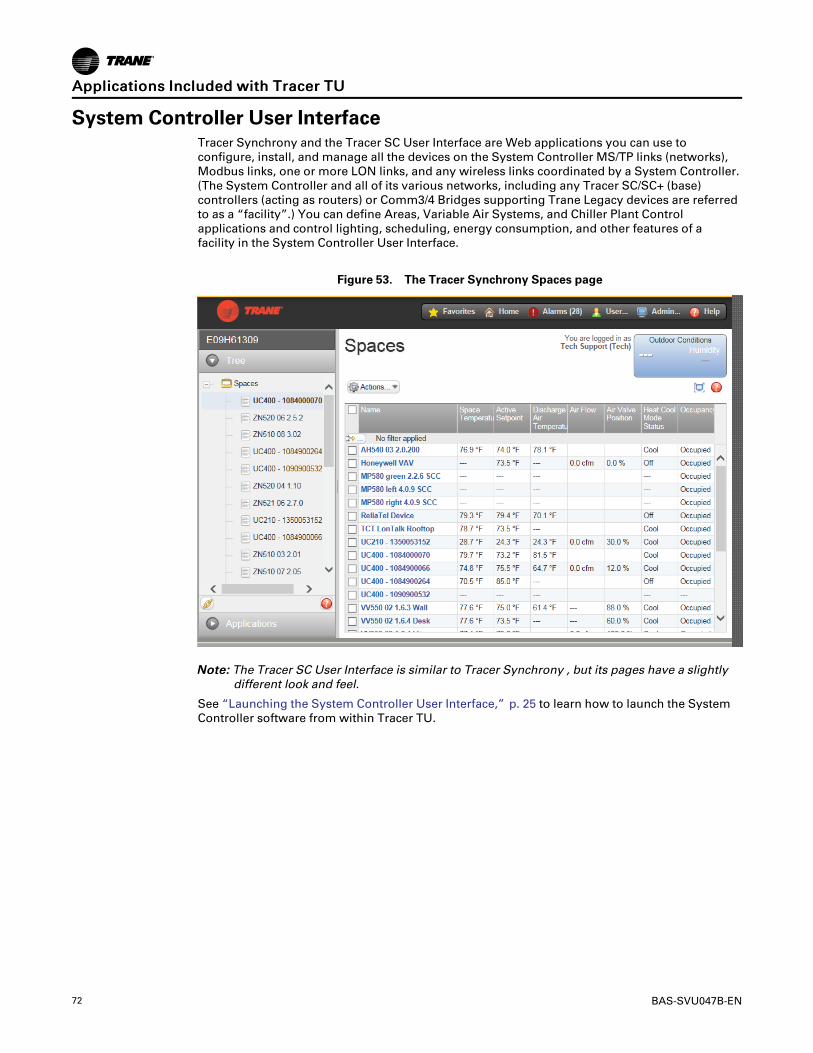
Launching the System Controller User InterfaceYou can launch the System Controller User Interface (either the Tracer SC User Interface orTracer Synchrony), a web based application that is used to configure the System Controller.
1. Right-click the SSyysstteemm CCoonnttrroolllleerr icon (orange area) at the top of the Device NavigationTree.
2. Click LLaauunncchh TTrraacceerr SSyynncchhrroonnyy or LLaauunncchh TTrraacceerr SSCC to start the application as shown inFigure 8, p. 26.
DDeevviiccee CCoonnnneeccttiioonnss
26 BAS-SVU047B-EN
Figure 8. Launching the System Controller Software from the Device Tree
If you connect directly to a System Controller with a USB cable, you can click the TTrraacceerr SSCC vviiaaUUSSBB icon or the TTrraannee CCoonnttrroolllleerr VViiaa UUSSBB icon installed on your desktop. (See “SystemController User Interface,” p. 72 for details.)
Tracer SC Via USB iconClick to launch the Tracer SC User Interface
Trane Controller Via USB iconClick to launch Tracer Synchrony
Check for Units of MeasureWhen you connect to a controller directly with a USB cable or indirectly by System Controllerpass-through or Single Link Access (see “ Single Link Access,” p. 69), Tracer TU determineswhether units have been specified for the controller. If no units have been specified, you areimmediately transferred to the Controller Settings tab screen where you can specify the units.This check for units ensures that units are defined before you proceed with configuration tasks.
DDeevviiccee CCoonnnneeccttiioonnss
BAS-SVU047B-EN 27
Tracer TU Interface Navigation and ControlsThe best way to explore Tracer TU is to examine its main utilities, which you can access thoughthe vertical tabs on the right side of the Tracer TU window or by using the Utilities menu at thetop of the screen. Click through these vertical tabs and examine the horizontal tabs associatedwith each of them. Later in this guide, you will be directed to the tutorial topics in the Tracer TUHelp file for more detailed descriptions.
The Location of the Utilities TabsThe main utilities tabs are located on the right side of the Tracer TU screen as shown in thefollowing figure.
NNoottee:: The following figures show details of the Tracer TU for Chillers screens. However, theTracer TU for Programmable Controllers utility tabs and their associated horizontal tabsare similar and use the same conventions..
Figure 9. The main utilities tabs
Associated Horizontal Tabs Main Utilities Tabs
Associated Horizontal TabsEach main tab has it own group of associated horizontal tabs. For example, when you click theEquipment Utility tab (the wrench icon shown above) in Tracer TU for Chillers, the followinghorizontal tabs appear at the top of the viewing area.
Figure 10. The horizontal tabs associated with the Equipment Utility tab
Click any one of these tabs to select it and display the corresponding screen. The selected tabturns white as shown in the previous figure. (Note that the Setpoints tab is selected by default.)
28 BAS-SVU047B-EN
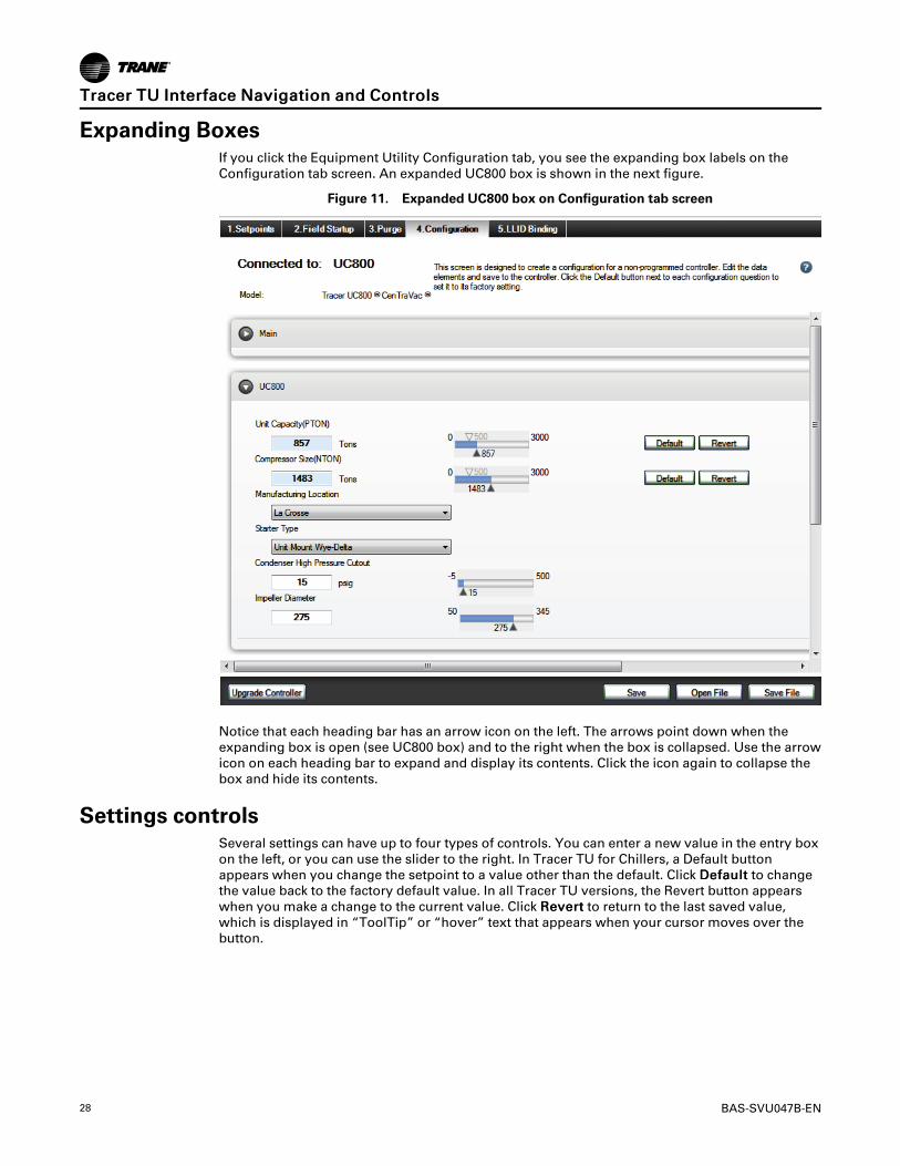
Expanding BoxesIf you click the Equipment Utility Configuration tab, you see the expanding box labels on theConfiguration tab screen. An expanded UC800 box is shown in the next figure.
Figure 11. Expanded UC800 box on Configuration tab screen
Notice that each heading bar has an arrow icon on the left. The arrows point down when theexpanding box is open (see UC800 box) and to the right when the box is collapsed. Use the arrowicon on each heading bar to expand and display its contents. Click the icon again to collapse thebox and hide its contents.
Settings controlsSeveral settings can have up to four types of controls. You can enter a new value in the entry boxon the left, or you can use the slider to the right. In Tracer TU for Chillers, a Default buttonappears when you change the setpoint to a value other than the default. Click DDeeffaauulltt to changethe value back to the factory default value. In all Tracer TU versions, the Revert button appearswhen you make a change to the current value. Click RReevveerrtt to return to the last saved value,which is displayed in “ToolTip” or “hover” text that appears when your cursor moves over thebutton.
A Brief Tour of Tracer TU for ChillersThe Unit Summary screen is the first screen to appear after startup. It is one screen in a group ofStatus Utility screens. It contains “at-a-glance” status information about the equipment to whichyou are connected. Notice that the Unit Summary screen shown in the following figure issubdivided using numbered group boxes.
Figure 12. The Status Utility—Unit Summary tab screen
NNootteess::
• The CDHG, CDHG, and CDHH (Duplex chiller) version pictured above is very similar tothe CVHE, CVHF, CVHG, CVHH, CVHL, and CVHS versions. However, it contains somedouble entries (Ckt1 and Ckt2) to account for the two compressor units.
• Other chiller models, such as Series R™ use similar user interface features.
The gray alert boxes at the top right provide vital information about the current mode, alarms,and the presence of active manual overrides. Two of the boxes are “hotspots” linked to otherStatus Utility screens. Clicking the CCuurrrreenntt MMooddee alert takes you to the Unit Status screen, andclicking the AAccttiivvee AAllaarrmmss alert takes you to the Alarms screen. (The MMaannuuaall OOvveerrrriiddee AAccttiivveealert is for display only.)
You can access the other Status Utility screens by clicking their corresponding horizontal tabsacross the top of the viewing area (UUnniitt SSttaattuuss, AAllaarrmmss, CCoonnttrroolllleerr SSttaattuuss, and EEvveenntt LLooggss).
NNoottee:: The Event Logs tab in the previous figure is included only with certain versions of theTracer AdaptiView software.
30 BAS-SVU047B-EN
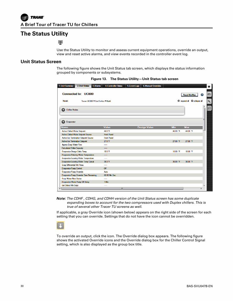
The Status Utility
Use the Status Utility to monitor and assess current equipment operations, override an output,view and reset active alarms, and view events recorded in the controller event log.
Unit Status ScreenThe following figure shows the Unit Status tab screen, which displays the status informationgrouped by components or subsystems.
Figure 13. The Status Utility—Unit Status tab screen
NNoottee:: The CDHF , CDHG, and CDHH version of the Unit Status screen has some duplicateexpanding boxes to account for the two compressors used with Duplex chillers. This istrue of several other Tracer TU screens as well.
If applicable, a gray Override icon (shown below) appears on the right side of the screen for eachsetting that you can override. Settings that do not have the icon cannot be overridden.
To override an output, click the icon. The Override dialog box appears. The following figureshows the activated Override icons and the Override dialog box for the Chiller Control Signalsetting, which is also displayed as the group box title.
AA BBrriieeff TToouurr ooff TTrraacceerr TTUU ffoorr CChhiilllleerrss
BAS-SVU047B-EN 31
Figure 14. The Status Utility—Override dialog box
When you activate an override, the icon turns blue indicating that the override is in effect. Somesettings allow an override to be in effect only for a predetermined duration. When you overridesuch a setting, a timed override icon with a clock image appears. If you place your cursor overthe icon, a text box appears indicating the amount of time remaining for the override to be ineffect.
Refer to the “Viewing Equipment Status and Settings (Status Utility)” inTracer TU Help forChillers for procedures explaining how to use the Status Utility screens. (For more informationabout Help, see “Accessing the Tracer TU Help for Chillers,” p. 37.
The Alarms ScreenThe Alarms tab screen displays both active alarms and historic alarms. (Alarms are also referredto as "diagnostics"). Historic alarms have either been resolved by the system or acknowledgedand resolved manually. There can be up to 100 alarms, both active and historic. For example, ifthere were 5 active alarms, the possible number of historic alarms would be 95.
You can also reset active alarms on this screen. Clicking Reset transfers active alarms to historyand allows the chiller to resume operation.
AA BBrriieeff TToouurr ooff TTrraacceerr TTUU ffoorr CChhiilllleerrss
32 BAS-SVU047B-EN
Figure 15. The chiller Alarms screen
The alarm icons displayed on the left side of the screen indicate the level of severity.
Red indicates an alarm requiring immediate attention.
Orange indicates a low priority alarm.
Blue indicates a normal condition.
Yellow indicates a warning alarm.
Green indicates unclassified information.
AA BBrriieeff TToouurr ooff TTrraacceerr TTUU ffoorr CChhiilllleerrss
BAS-SVU047B-EN 33
The Controller Status ScreenThe read-only Controller Status tab screen lists controller information including the applicationpart number, its model type, controller serial number, build part number, boot part number,sales order number, unit model number, and unit serial number.
The Event Logs ScreenThe Event Logs tab screen displays events that led up to a chiller shutdown. The UC800 event logis generated on a demand basis and can contain up to 5000 events. Each event record indicatesthe type of event (alarm, circuit, chiller, and so on), the date and time of the event, a briefdescription of the event, and a small set of related data items and their values. The log columnsare sortable. Click the heading of any column to change the sort order of the table (alternatingbetween ascending to descending).
The Manual Overrides ScreenThe Manual Overrides screen shown in Figure 16, p. 33 provides one location where you canperform key manual overrides for CenTraVac™, RTAE, RTAF, RTHA-B, and RTHC-D chillers. Youcan then monitor specific point values related to an override when it is in effect. The CenTraVac ,RTAE, RTAF, RTHA-B, and RTHC-D versions of this screen include sets of points appropriate toeach model.
Figure 16. The Status Utility - Manual Overrides screen for RTAF
See the “Manual Overrides” subsection under the “Screens and Dialog Boxes” section in theTracer TU Help for Chillers for a description of the various overrides and the points that aremonitored during the overrides.
AA BBrriieeff TToouurr ooff TTrraacceerr TTUU ffoorr CChhiilllleerrss
34 BAS-SVU047B-EN
Controller Settings Utility
Use the Controller Settings Utility to enter Date and Time formats and the units of measure inwhich values are displayed (either inch-pound [I-P] or Standard International Units [SI]). TheController tab screen also includes a Protocol expanding box where you can change protocolsettings, such as the Baud Rate and Software Device ID.
The Controller Settings Utility also includes the Operator Display screen on which you can enablesecurity so personnel can modify Tracer AdaptiView display settings only by entering specifiedPIN numbers.
Refer to the “Modifying Controller Settings (Controller Settings Utility)” section in the Contentsof theTracer TU Help for Chillers for procedures explaining the use of the Controller SettingsUtility screens.
AA BBrriieeff TToouurr ooff TTrraacceerr TTUU ffoorr CChhiilllleerrss
BAS-SVU047B-EN 35
Equipment Utility
Use the Equipment Utility Configuration screen to define chiller components, features, andcapabilities based on the selected chiller model. (See “Tracer TU Interface Navigation andControls,” p. 27 for an image of the Configuration tab screen.) The configuration determines therequired set of Low Level Intelligent Devices (LLIDs), and how the chiller application is run in thecontroller (UC800). You can then use the Configuration, Setpoints, Field Startup, and Purgescreens to verify or modify chiller setpoints and configuration settings. The following figureshows the LLID Binding tab screen, which you can use to verify, bind, unbind, sequence,reassign, and upgrade Low-Level Intelligent Devices (LLIDs).
Refer to “Configuring or Changing Chiller Settings (Equipment Utility)” in the Tracer TU Help forChillers for procedural and conceptual information about using the Equipment Utility screens.
AA BBrriieeff TToouurr ooff TTrraacceerr TTUU ffoorr CChhiilllleerrss
36 BAS-SVU047B-EN
Chiller ReportsYou can generate the following types of reports from the Tracer TU Reports menu. These reportscan be archived or printed. You can also convert these reports to PDF format for e-mailing tocustomers.
• ASHRAE Chiller Report
Tracer TU generates a printable ASHRAE Chiller Report that lists a number of setpoints. Youcan enter job site information and notes, and then save the report. Finally, you can save thereport in PDF format for your customer.
• Event Log Report
Lists all the events visible on the Event Log tab screen. (There are no required entries orsetup; the report is generated when you select Event Log Report on the Reports menu.)
In addition to the report options, the Reports menu includes the following functional options.
• VViieeww RReeppoorrttss—Presents an Open File dialog box on which you can select archived reportsfor viewing.
• CCoonnvveerrtt RReeppoorrttss ttoo PPDDFF——Opens the Convert Reports to PDF dialog box on which you canselect archived reports and convert them to PDF format.
AFD3 Firmware UtilityThe AFD3 Firmware Utility provides an efficient way to upgrade the Adaptive Frequency Drive 3firmware on the rare occasion when it is necessary. The utility also supports AFD3 configurationand event history archive and configuration restore operations.
Figure 19. The AFD3 Firmware Utility
AA BBrriieeff TToouurr ooff TTrraacceerr TTUU ffoorr CChhiilllleerrss
BAS-SVU047B-EN 37
Accessing the Tracer TU Help for ChillersAs you work with Tracer TU, you can refer to the Help for screen descriptions, procedures, andreference information covering the major Tracer TU features and capabilities.
Access MethodsYou can access Help in the following ways:
• Clicking the Help icon (a question mark in a blue circle), which is located in the upper rightportion of each screen.
• Clicking the Help button on many dialog boxes.
• Clicking the Help menu at the top of the application window and selecting the Help option.
• Moving your cursor over various tabs and buttons to view “tool tip” text.
Quick Start TutorialThe Quick-Start Tutorial topics provide more detail on the Tracer TU interface features anddemonstrate some processes and procedures. (The Quick-Start Tutorial book is highlighted inthe following figure).
Figure 20. Tracer TU Help for Chillers table of contents
AA BBrriieeff TToouurr ooff TTrraacceerr TTUU ffoorr CChhiilllleerrss
38 BAS-SVU047B-EN
A Brief Tour of Tracer TU for Programmable ControllersTracer TU for Programmable Controllers presents the Unit Summary screen at startup. Thecontents of the Unit Summary screen vary depending on the controller to which you areconnected. If you connect to a System Controller, you will first see the System Controller UnitSummary screen. You can then connect to any communicating controllers on the SystemController’s links.
The Unit Summary Screen (System Controller)The Unit Summary screen is displayed when you are connected to a System Controller.
Figure 21. Status Utility—The Unit Summary screen (System Controller version)
You can now perform either of the following actions:
• Right-click the SSyysstteemm CCoonnttrroolllleerr icon (orange area) at the top of the Device Navigation Treeand then click LLaauunncchh TTrraacceerr SSyynncchhrroonnyy or LLaauunncchh TTrraacceerr SSCC (depending on the device towhich you are connected) to start the System Controller User Interface. (See “SystemController User Interface,” p. 72.)
• Connect to one of the BACnet, LON, Trane Legacy, or Modbus devices displayed in the devicehierarchy on the Device Navigation Tree pane on the left side of the Tracer TU window byright-clicking it and selecting CCoonnnneecctt ttoo DDeevviiccee. You can then perform tasks using theavailable Tracer TU utilities and applications.
NNoottee:: You can view the special Unit Summary and Unit Status screens for Non-Trane BACnet,LON, Trane Legacy, and Modbus devices.
BAS-SVU047B-EN 39
Unit Summary Screen (UC210, UC400, and UC600)If you are connected to a UC210, UC400, or UC600 when you start Tracer TU, or if you connect toa device through a System Controller, you first see the Unit Summary screen, which is associatedwith the Status Utility tab at the right. It is one screen in a group of Status Utility screens. Itcontains “at-a-glance” status information about the device to which you are connected. Thefollowing figure shows the UC400 version of the Unit Summary screen.
Figure 22. Status Utility—The Unit Summary screen (UC400 version)
The gray alert boxes at the top right provide vital information about the points that are out ofservice, any active alarms, and the presence of active overrides. Clicking the AAccttiivvee AAllaarrmmss alerttakes you to the Alarms screen. (The PPooiinnttss OOuutt ooff SSeerrvviiccee and AAccttiivvee OOvveerrrriiddeess alerts are fordisplay only.)
The UC600 version provides only the connection information and the three alert boxes, and, ifthe UC600 has a TD7 Display, the Unit Summary screen includes a button you can click to launchthe Operator Display User Interface.
Figure 23. Operator Display User Interface button on the UC600 Unit Summary screen
NNoottee:: Most Tracer TU for Programmable Controllers screens are similar to the UC400 screensshown in this section.
AA BBrriieeff TToouurr ooff TTrraacceerr TTUU ffoorr PPrrooggrraammmmaabbllee CCoonnttrroolllleerrss
40 BAS-SVU047B-EN
Unit Summary and Unit Status Screens (Modbus, LonTalk, Non-TraneBACnet, and Trane Legacy Devices)
If you connect to a Modbus, LonTalk, Non-Trane BACnet, or Trane Legacy device using SystemController pass-through, Tracer TU displays groups of significant device data points on specialUnit Summary and Unit Status screens. These screens are similar in format to the normal TraneBACnet screens.
• Unit Summary
The contents of the Unit Summary screen are similar to the contents of the Application tabpage on the corresponding individual Device page in the System Controller User Interface.The amount of data displayed in Tracer TU depends on the device type.
• Unit Status
The Unit Status screen lists point values grouped by main components similar to the normalTrane BACnet screens.
Some point values on these two screens are presented in blue text, which are the SystemController (converted) values.
Figure 24. Unit Status screen with convertible points
The values displayed in bluetext are the System Controllervalues.
You can click any of these values to change them to their native controller (communicated) valueas shown in the following figure.
Figure 25. System Controller Value Toggled to Controller Value
If the point can be overridden, you can use either value for the override.
AA BBrriieeff TToouurr ooff TTrraacceerr TTUU ffoorr PPrrooggrraammmmaabbllee CCoonnttrroolllleerrss
BAS-SVU047B-EN 41
The Status UtilityThe Status Utility has a set of horizontal tabs providing access to its screens. Use the StatusUtility screens to monitor performance and to create, edit, delete, override, and compare pointsusing the Action drop-down list and the right-click menus on the AAnnaalloogg, BBiinnaarryy, and MMuullttiissttaatteescreens. In addition, the AAllaarrmmss screen displays active alarms and the CCoonnttrroolllleerr SSttaattuuss screenprovides information about the status of the controller, its installed programs, and expansionmodules. Finally, the CCoonnttrroolllleerr SSeettttiinnggss screen is where you can configure expansionmodules, wireless sensors, notification classes, communication settings, the controller date andtime, and controller units.
Binary Tab ScreenThe following figure shows the Binary tab screen, which lists the binary inputs, outputs, andvalues that reside on the controller and are used by the installed programs. (The Analog andMultistate screens have a similar format.) You can create, edit, copy, and delete points fromthese screens and then send the changes to the device or an offline Controller Configuration.Refer to the “Configuring and Managing Points” section in the Tracer TU Help for ProgrammableControllers.
NNoottee:: The padlock icons in the Lock column on the right, signify that the points are Factorysupplied and are, therefore, not editable. The lock applies to most equipment with someexceptions. You can edit some points in Trane factory blower coil, fan coil, and unitventilator configurations. See “Trane Factory Blower Coils, Fan Coils, and Unit Vents” inthe Tracer TU Help for Programmable Controllers and “Factory Equipment ConfigurationsYou Can Modify (UC210 and UC400),” p. 57 of this guide for more information.
Figure 26. The Status Utility—Binary tab screen
You can click the Override icon (down arrow icon) in the grid to bring up either an OverrideRequest dialog box (used for output or value points) or a Change Service Request dialog box(used for input points).
AA BBrriieeff TToouurr ooff TTrraacceerr TTUU ffoorr PPrrooggrraammmmaabbllee CCoonnttrroolllleerrss
42 BAS-SVU047B-EN
Alternatively you can right-click within the row of any point and select either the Override orChange Service options on the right-click menu, which is shown in the next figure, to display thesame dialog boxes. Select Details on the right-click menu to view specific information about apoint.
Figure 27. Right-click menu on the Status Utility Analog, Binary, and Multistate screens
The next figure shows the Override Request dialog box. The selected point name is displayed atthe top of the dialog box. You can use the Override Request dialog box to either override a pointor take it out of service.
Figure 28. Override Request dialog box
• Override the point using a different value and priority level. When you specify an override onthis dialog box, a blue Override icon appears in the Control column of the Status Utility tabscreen indicating that the override is in effect. You can also set the amount of time (DurationLimit) that the override will be in effect. If you set a Duration Limit, the Override icon includesa clock image. If you place your cursor over the icon, a text box appears indicating theamount of override time remaining.
AA BBrriieeff TToouurr ooff TTrraacceerr TTUU ffoorr PPrrooggrraammmmaabbllee CCoonnttrroolllleerrss
BAS-SVU047B-EN 43
• Taking a point out of service cuts off the connection with the point’s reference. Bydisconnecting the point from its reference, you can substitute a temporary value for testingpurposes or port a program and its points to another device before transitioning theequipment to the new program.
Refer to the “Overriding Points” section in the Tracer TU Help for Programmable Controllers forprocedures explaining how to specify and release an override. (For more information about Helpsee “Accessing the Tracer TU Help for Programmable Controllers,” p. 65.)
NNoottee:: You can also override the same point on multiple devices using the group overridecapability. See “Facility View,” p. 61 for information about this capability.
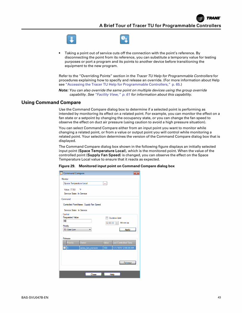
Using Command CompareUse the Command Compare dialog box to determine if a selected point is performing asintended by monitoring its effect on a related point. For example, you can monitor the effect on afan state or a setpoint by changing the occupancy state, or you can change the fan speed toobserve the effect on duct air pressure (using caution to avoid a high pressure situation).
You can select Command Compare either from an input point you want to monitor whilechanging a related point, or from a value or output point you will control while monitoring arelated point. Your selection determines the version of the Command Compare dialog box that isdisplayed.
The Command Compare dialog box shown in the following figure displays an initially selectedinput point (SSppaaccee TTeemmppeerraattuurree LLooccaall), which is the monitored point. When the value of thecontrolled point (SSuuppppllyy FFaann SSppeeeedd) is changed, you can observe the effect on the SpaceTemperature Local value to ensure that it reacts as expected.
Figure 29. Monitored input point on Command Compare dialog box
AA BBrriieeff TToouurr ooff TTrraacceerr TTUU ffoorr PPrrooggrraammmmaabbllee CCoonnttrroolllleerrss
44 BAS-SVU047B-EN
If you select Command Compare from a value or output point, the dialog box appears with thevalue or output displayed in the Controlled Point box. You then select the monitored point forthat control point.
NNootteess::
• When you change a point’s value you are performing an actual override of the point.Be sure to release the override when you are finished.
• If the controlled point is locked, your override request is ignored.
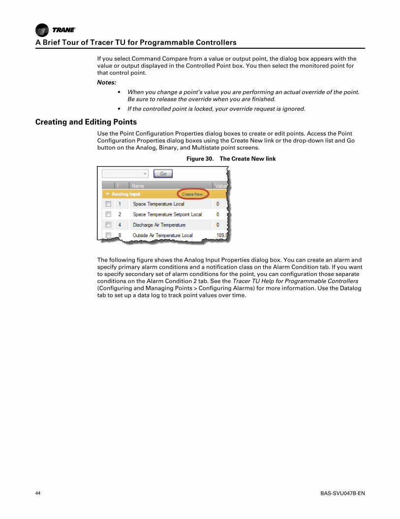
Creating and Editing PointsUse the Point Configuration Properties dialog boxes to create or edit points. Access the PointConfiguration Properties dialog boxes using the Create New link or the drop-down list and Gobutton on the Analog, Binary, and Multistate point screens.
Figure 30. The Create New link
The following figure shows the Analog Input Properties dialog box. You can create an alarm andspecify primary alarm conditions and a notification class on the Alarm Condition tab. If you wantto specify secondary set of alarm conditions for the point, you can configuration those separateconditions on the Alarm Condition 2 tab. See the Tracer TU Help for Programmable Controllers(Configuring and Managing Points > Configuring Alarms) for more information. Use the Datalogtab to set up a data log to track point values over time.
AA BBrriieeff TToouurr ooff TTrraacceerr TTUU ffoorr PPrrooggrraammmmaabbllee CCoonnttrroolllleerrss
BAS-SVU047B-EN 45
Figure 31. Analog Input Properties dialog box accessed from the Analog tab screen
If you want to add the selected standard point or a custom point to the System Controllertemplate, you can select the AAdddd ttoo SSCC TTeemmppllaattee check box in the System Configuration groupbox. You can also specify a trend interval for the point by selecting the Trend Interval check box.Finally, you can optionally enter a meaningful description of the point and its function in theDescription entry box.
The Alarms ScreenThe Alarms tab screen displays all active alarms.
Figure 32. The Alarms screen
AA BBrriieeff TToouurr ooff TTrraacceerr TTUU ffoorr PPrrooggrraammmmaabbllee CCoonnttrroolllleerrss
46 BAS-SVU047B-EN
Alarms are displayed in date and time order and then in order of severity. However, all columnsare sortable. For example, if you prefer to view alarms by Point Name, you can click that columnheading to arrange the entries in ascending or descending alpha order.
NNoottee:: See the alarm icons listed in“The Alarms Screen,” p. 31 for a description of the variousicons displayed on the left side of the screen.
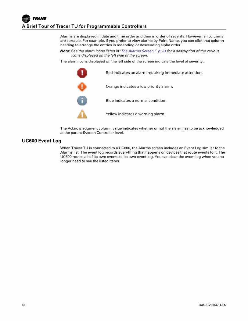
The alarm icons displayed on the left side of the screen indicate the level of severity.
Red indicates an alarm requiring immediate attention.
Orange indicates a low priority alarm.
Blue indicates a normal condition.
Yellow indicates a warning alarm.
The Acknowledgment column value indicates whether or not the alarm has to be acknowledgedat the parent System Controller level.
UC600 Event LogWhen Tracer TU is connected to a UC600, the Alarms screen includes an Event Log similar to theAlarms list. The event log records everything that happens on devices that route events to it. TheUC600 routes all of its own events to its own event log. You can clear the event log when you nolonger need to see the listed items.
AA BBrriieeff TToouurr ooff TTrraacceerr TTUU ffoorr PPrrooggrraammmmaabbllee CCoonnttrroolllleerrss
BAS-SVU047B-EN 47
The Controller Status ScreenThe Controller Status tab screen lists basic information about the controller, the installedprograms, and any expansion modules used with the controller.
Figure 33. The Controller Status screen
Configuration SummaryDisplays a quick summary of basic controller and configuration information. In addition, you canedit the Unit Tag, Unit Model Number, Unit Serial Number, and the Unit Sales Order Number byclicking the icon on the right side of the title bar.
ProgramLists all installed programs. The grid includes information about current program status(Running or Idle) and specifies whether a program is scheduled to run at a specific interval, or if itruns when triggered by an event. The Duration column indicates the length of time it takes aprogram to run from start to completion (one program cycle).
ApplicationsDisplays the operational state of the TGP2 program engine in which all programs executeincluding the amount of volatile memory used for TGP2 control in the connected device and thepercentage of non-volatile memory used to store TGP2 programs and the configuration in a theconnected device.
AA BBrriieeff TToouurr ooff TTrraacceerr TTUU ffoorr PPrrooggrraammmmaabbllee CCoonnttrroolllleerrss
48 BAS-SVU047B-EN
Expansion Module StatusThe Expansion Modules Status box appears if the controller is communicating with anyexpansion modules, such as the XM30 or XM70 modules. The grid columns include module type,address, and communication status.
ControllerThe Controller box provides identifying information about the controller.
The Controller Settings ScreenFinally, use the CCoonnttrroolllleerr SSeettttiinnggss tab screen to accomplish the following tasks:
• Enter Date and Time formats used by the controller.
The UC600 includes advanced date-time functions that provide the ability to
– Set the time zone for the controller.– Enable Daylight Savings Time (DST) and set the DST start and end dates.– Set the current time on the controller.
• Change protocol settings, such as the Baud Rate and Software Device ID.
• Discover, add, or delete XM30, XM32, and XM70 expansion modules.
• Discover, add, or delete wireless space, humidity, CO2, and occupancy sensors.
• Specify the units of measure used by the controller.
• Create, edit, and delete unit controller notification classes.
(See the “Modifying Controller Settings” section in the Tracer TU Help for ProgrammableControllers.
Figure 34. The Controller Settings screen
AA BBrriieeff TToouurr ooff TTrraacceerr TTUU ffoorr PPrrooggrraammmmaabbllee CCoonnttrroolllleerrss
BAS-SVU047B-EN 49
Data Graphing Utility
Use the Data Graphing Utility to set up and perform the following tasks:
• Configuring data logs.
Configure data logs on the companion Data Log Setup screen, which provides the mostdetailed data log configuration. You can also use the quick data log configuration controls onthe Datalog tab of each Point Configuration dialog box (see “Creating and Editing Points,” p.44). Each data log records data for a single point.
• Generating line graphs
At a time of your choosing, retrieve and view point data recorded over a time span and storedin the controller’s data logs. Set up and generate line graphs (trends) on the View Graphs tabscreen. Each graph displays data for a single point (one data log file) you retrieved from thecontroller using the Retrieve Data Logs option on the Tools menu.
Figure 35. Data Graphing Utility—View Graphs tab screen
You can save and print the graphing image or graph data. You can also save log file datato other file formats for viewing and analysis.
Refer to the “Configuring and Graphing Data Logs“ section in the Tracer TU Help forProgrammable Controllers for procedures explaining how to use the Data Graphing Utilityscreens. More specifically, see the topic “Graphing Data From Archived Log Files” forinformation about viewing UC400, UC210, and UC600 data logs.
AA BBrriieeff TToouurr ooff TTrraacceerr TTUU ffoorr PPrrooggrraammmmaabbllee CCoonnttrroolllleerrss
50 BAS-SVU047B-EN
Equipment Utility
Use the Equipment Utility tab screens to configure and commission equipment. In addition, theUC600 Equipment Utility contains the Scheduling screen used to set up three different schedules.
Configuration and Setup ScreensThe following figure shows the Configuration tab screen where you can create the equivalent of aFactory configuration for the type of equipment specified on the Device Type and EquipmentType drop-down lists. For example, when you select VAV in the Equipment type box, other boxesappear from which you can make specific selections. After you have made all selections, clickSave to clear any previous configuration off the controller and to load the new programs andpoints.
The following figure shows the Configuration tab screen where you can create or modify pointsand adjust specific equipment parameters.
IImmppoorrttaanntt:: Modifying a factory configuration should only be done if absolutely necessary, andonly if you are knowledgeable about the effects of the proposed changes. You areresponsible for the proper operation of the equipment if any changes are made tofactory configurations.
NNoottee:: If you replace an existing configuration with a factory configuration, any uniquely namedcustom (user-created) data logs , custom points, and programs are preserved. If a conflictexists between custom points and factory points, Tracer TU issues a message stating thatthe conflict must be resolved before you can load the factory equivalent configuration. Youmust delete or reassign the custom point causing the conflict.
(See the “Configuring and Commissioning Equipment” section in the Tracer TU Help forProgrammable Controllers.)
AA BBrriieeff TToouurr ooff TTrraacceerr TTUU ffoorr PPrrooggrraammmmaabbllee CCoonnttrroolllleerrss
BAS-SVU047B-EN 51
The Setpoints and Setup Parameters tabs to the left of the Configuration tab display screens thathave sets of entry boxes and sliders you can use to specify the values of various equipmentsetpoints and parameters.
The Commissioning ScreenAs its name suggests, the Commissioning tab screen is where you run Air and Water Balancingand Auto-Commissioning routines and update setpoints specific to those processes.
NNoottee:: The Commissioning and Air/Water Balancing functions are also available on the FacilityView where you can perform them for groups of devices.
The Commissioning tab screen displays specific parameters related to air flow, fan, and waterflow. It has the following expanding boxes: Actions, Operating Status, ECM Fan Setup (if an ECMfan exists), Current Calibration Summary (for VAV boxes), and Discharge Air Reset Limits (forVAV boxes).
Figure 37. The Commissioning screen
The Actions box includes screen objects you can use to launch the following tasks on anindividual VAV box:
• Zero Air and Water Valve Position
Launches the Auto-Calibration routine to completely close the air or water valve and resetsthe Actual Air Valve Position point value to 0 (zero).
• Calibrate Air Valve
Displays the Calibrate Air Valve dialog box, which you can use to perform a two-point airvalve calibration for an individual VAV box.
• Calibrate Hot Deck Air Valve
Displays the Hot Deck Air Valve Balancing Steps dialog box, which you can use to perform atwo-point air flow calibration for an individual dual duct VAV box.
AA BBrriieeff TToouurr ooff TTrraacceerr TTUU ffoorr PPrrooggrraammmmaabbllee CCoonnttrroolllleerrss
52 BAS-SVU047B-EN
• Air Flow Override
Displays the Air Flow Override dialog box, which you can use to safely drive the air valve toFull Open position (or, alternatively, to Full Closed, Maximum Flow, or Minimum Flowposition) without the risk of recalculating calibration values.
• Water Valve Related Overrides
Displays one of the water valve related override dialog boxes. (The Hot Water Valve OverrideStart button is shown on the previous image.) You can override the Economizer Valve,Isolation Valve, Hot Water Valve, and Chilled Water Valve to the open position for a limitedduration as part of a system water balancing operation. When the time duration expires thewater valve is released back to its normal setting..
• Fan Related Overrides
The Fan Override, Fan Override ECM, and Fan Override PSC options display the fan relatedoverrides dialog boxes, which you can use when balancing air flow for the supported types ofequipment.
• Ventilation Damper Override
Use this override dialog box to open the ventilation damper on all BC, FC, and UV unitsconfigured with modulating outside air dampers. The damper can be opened to an adjustablepercent.
Operating StatusThis box includes current settings related to air and water balancing. The gray override iconsindicate that air, fan, and water valve settings can be overridden. Blue icons indicate that thesettings are currently overridden. (See “Binary Tab Screen,” p. 41.)
ECM Fan Setup(Visible if an ECM fan is configured.) This box includes flow setpoint, maximum and minimumflow settings, and a correction factor setting.
Current Calibration SummaryPresents the current values of the Air Flow Gain and Air Flow Measurement Offset along with theMinimum and Maximum Air Flow Setpoints for a VAV box. . The following setpoints have beenadded to this list:
• Standby Minimum Air Flow
• Air Flow Setpoint Minimum Standby Heat
• Air Flow Setpoint Minimum Heat
• Air Flow Setpoint Maximum Heat
• Air Flow Setpoint Minimum Local Heat
Discharge Air Reset LimitsThis box contains settings that are used for Dual Max VAV boxes. When the VAV’s heating valveis open, the box flow will modulate between the flow settings to control to the Discharge AirTemp Design Setpoint. It includes the following adjustable setpoints:
• Air Flow Setpoint Reset Min Local Heat
• Air Flow Setpoint Reset Max Local Heat
• Discharge Air Temp Reset Max
• Discharge Air Temp Design Setpoint
AA BBrriieeff TToouurr ooff TTrraacceerr TTUU ffoorr PPrrooggrraammmmaabbllee CCoonnttrroolllleerrss
BAS-SVU047B-EN 53
UC600 Scheduling ScreenThe UC600 supports up to three schedules a customer can access, set up, view, and maintain onthe Tracer TD7 Display. Tracer TU also provides schedule set up and maintenance screens in theEquipment Utility.
Schedules are built on a series of user entered “events” that occur on each day of the week. Anevent is a change in a value applied to a group of points at a specific time that can occur duringany day of the week. Each day is treated as a separate entity that can have up to ten events.
Of course, customers will need to enter “exceptions” to this schedule for specific dates andtimes. For example, on holidays when the building is unoccupied, exceptions are entered to keepthe building at the unoccupied temperature. Exceptions can be configured for a single date or torecur on a user-defined recurrence pattern such as the third Thursday of the month.
The primary purpose of the events and exceptions in a schedule is to change the values within apiece of equipment or outputs controlled by the UC600. This is done by assigning points as“members” of a schedule. When a specific time of an event is encountered by the schedule, itcontrols the members to the value of the event. Exceptions are used to:
• Override an entire day
• Extend or change a schedule’s events over a normal daily schedule
Each schedule can control up to 10 points (members), which must be of the same type (analog,binary, or multistate) and, in the case of analog points, the same unit type (temperature,pressure, and so on). The UC600 can support up to 25 exceptions in a single schedule. Use of oneexception per day is recommended, as each exception can have up to 10 of its own events.
See “Setting Up and Maintaining UC600 Schedules” in the Tracer TU Help for ProgrammableChillers for more detailed information.
The following figure shows the Scheduling screen.
Figure 38. Equipment Utility - Scheduling screen
AA BBrriieeff TToouurr ooff TTrraacceerr TTUU ffoorr PPrrooggrraammmmaabbllee CCoonnttrroolllleerrss
54 BAS-SVU047B-EN
Custom Reports for Tracer™ TD7 Display (UC600)You can configure three custom reports for the Tracer TD7 Display on the Equipment UtilityDisplay Reports screen. Each report can include real time values for up to 27 data points. You canthen view these reports either on the Tracer TD7 or from within Tracer TU.
NNoottee:: To configure and view Custom Reports, the UC600 must have Version 2 or higher firmwareloaded. If the UC600 is running on Version 1, you must first upgrade the firmware.
You can configure custom reports for the customer using the following capabilities:
• Specify a report name meaningful to your customer.
• Specify a high interest data point for display in a header area at the top of the report screen.
• Configure reports online or offline. (Dashes are substituted for values during offlineconfiguration.)
• Configure reports using System Controller pass-through or Single Link Access.
• Save the report configuration to file or to the UC600.
You can also restrict access to report definitions by establishing access privileges for up to eightuser-ids.
TD7 Display Preferences and Security ScreensUse the TD7 Display Preferences screen to specify a language preference, date and time format,display units, and a home page for the TD7 Display. Use the Security screen to restrict access tothe TD7 Display to designated users.
AA BBrriieeff TToouurr ooff TTrraacceerr TTUU ffoorr PPrrooggrraammmmaabbllee CCoonnttrroolllleerrss
BAS-SVU047B-EN 55
Additional Tracer TU for Programmable Controllers FeaturesTracer TU supports the following additional features on the UC210, UC400, and UC600.
Access to Devices on Wireless NetworksTrane wireless networking provides a wireless communication solution for Tracer buildingautomation systems that saves planning, installation time, and the expense associated with fullywired systems. The Trane® Air-Fi™ Wireless Communications Interface (WCI) enables wirelesscommunication between system controls, unit controls, and wireless sensors. The WCI replacesthe need for communication wire in all system applications.
You can use Tracer TU to access the following devices that are members of a Trane wirelessnetwork:
• The Tracer® SC+ System Controller and the Tracer® SC system controller
• Tracer ®UC210 programmable controller
• Tracer® UC400 programmable controller
• Tracer® UC600 programmable controller
• BCI-I: BACnet® Communications Interface for IntelliPak™ systems
• BCI-R: BACnet® Communications Interface for ReliaTel™ systems
Connection ComponentsFrom a servicing and maintenance standpoint, wireless networking allows you to use the TracerTU service tool with the Tracer TU Adapter (Wired/Wireless) to communicate wirelessly from anycontroller to any other controller in a network. Using the Tracer TU Communication Adapter(Wired/Wireless) in wireless mode, you can connect to any wireless device in a network and thendiscover, access, and service that device or another member device in the network. Thiscapability provides the flexibility and convenience you need to finish jobs in less time.
Figure 40. Wireless access through the Tracer TU Communication Adapter
AA BBrriieeff TToouurr ooff TTrraacceerr TTUU ffoorr PPrrooggrraammmmaabbllee CCoonnttrroolllleerrss
56 BAS-SVU047B-EN
Accessing Wireless NetworksPerform the following steps to access devices on a wireless network:
1. Connect the Tracer TU Adapter (Wired/Wireless) to your PC with a USB cable.
2. Start Tracer TU and select the TTUU AAddaapptteerr --WWiirreelleessss option on the Startup Task Panel.
3. Click CCoonnnneecctt.
Tracer TU displays the Wireless Networks dialog box shown in the following figure.
Figure 41. Wireless Network Utilities
You can then join one of the displayed networks. An open padlock indicates a network thathas no System Controller and does not require log-in credentials. A closed padlock indicatesa secure network coordinated by a WCI attached to a System Controller.
Tracer TU Wireless Networking CapabilitiesYou can use Tracer TU to perform many wireless network tasks:
• Creating a network
• Listing network devices
• Opening a network for joining
• Closing a network when joining is complete
• Viewing the Wireless Network Summary Report and a graphical map of the network to assessnetwork health, connection strength, the number of hops between the coordinator and eachmember device, and to view sensor information on the graphical map including IDs, signalstrength, and last reception time
• Viewing network details and advanced information
• Viewing sensor health status
• Removing a device from the network
• Disbanding the network
For detailed information see the following documents:
• The "Accessing Wireless Devices and Maintaining Networks" section of the Tracer TU Helpfor Programmable Controllers.)
• Air-Fi™ Wireless Comm Installation, Operation, and Maintenance (BAS-SVX40)
• Air-Fi™ Wireless Comm Network Design Best Practices Guide (BAS-SVX55)
AA BBrriieeff TToouurr ooff TTrraacceerr TTUU ffoorr PPrrooggrraammmmaabbllee CCoonnttrroolllleerrss
BAS-SVU047B-EN 57
Controller ConfigurationsA Controller Configuration is a complete device definition that includes everything in onepackage that is required to operate the controller and run the equipment: the points, TGP2programs (.tgp2 and .bc files), data logs, alarms, a graphic, and internal template information. Inaddition, while you are connected to an operating controller, you can save the entireconfiguration contents as a Controller Configuration. Alternatively, you can create a ControllerConfiguration manually by (1) using the Equipment Utility Configuration screen in offline modeto create a factory configuration or (2) starting with existing programs and a points file to create ageneric or custom configuration.
You can create a factory configuration for a variety of devices in offline mode including Traneblower coils, fan coils, VAV boxes, and water source heat pumps controlled by UC400s orUC210s. The standard configurations include points, programs, and a standard graphic.
You can use the normal Tracer TU and TGP2 Editor interface screens to assemble a newController Configuration or to edit a saved Controller Configuration. The internal templateinformation is kept up to date. Changes you can make include:
• Changing TGP2 programs or adding new programs
• Adding, editing, or deleting standard or custom points (See “Adding Standard and CustomKeys to Controller Templates” in the Tracer TU Help for Programmable Controllers forinformation about adding keys for custom points to the System Controller template.)
NNoottee:: Some locked points and “factory infrastructure” programs in standard configurationscannot be edited. However, you can break the "factory seal" on points for someequipment types. (See “Factory Equipment Configurations You Can Modify (UC210and UC400),” p. 57 .)
• Configuring data logs using the Datalog tab on the Point Configuration Properties dialog box
• Configuring alarms using the Alarm Condition tab on the Point Configuration Propertiesdialog box
• Specifying a standard graphic for a custom configuration
• Editing TD7 graphics
• Creating or editing UC600 schedules
You can then transfer the Controller Configuration to one or more similar devices. The ControllerConfiguration does not overwrite identifying information on the target devices. (See “AnOverview of Controller Configurations” in the Tracer TU Help for Programmable Controllers formore information.)
NNoottee:: If you want to download a Controller Configuration to several similar devices, it is moreefficient to first download the Controller Configuration to a single device , back up thatdevice, and then download the backup file to the remaining devices. (See “BackupUtility,” p. 67 for more information.
Factory Equipment Configurations You Can Modify (UC210 and UC400)Trane factory blower coils, fan coils, and unit ventilators initially use standard configurationscreated on the Tracer TU Configuration screen. However, these equipment types allow certainmodifications to the factory configurations.
IImmppoorrttaanntt:: Modifying a factory configuration should be done only if absolutely necessary, andonly if you are knowledgeable about the effects of the proposed changes. You areresponsible for the proper operation of the equipment if any changes are made tofactory configurations.
Editable Points and ProgramsTracer TU allows you some freedom to open and edit the factory points and programs to suit jobrequirements. For example, you may need to make common modifications to a blower coil or fancoil configuration, such as adding valves to a blower coil.
When you make changes to factory programs or points, you must first explicitly acknowledgethat you are modifying them. The programs and points are then transitioned to a "Factory-FieldModified" state, which enables the editing capability.
AA BBrriieeff TToouurr ooff TTrraacceerr TTUU ffoorr PPrrooggrraammmmaabbllee CCoonnttrroolllleerrss
58 BAS-SVU047B-EN
NNoottee:: Points with command locks cannot be unlocked. Command locks prevent you fromoverriding the point. However, you can safely override most points with command locksby using a request point, such as a Multistate Value.
Points and Programs That Cannot be ModifiedYou can make changes to programs and the points they reference that generate the I/O controlsignals to hardware terminations on the controller. You can edit only these “I/O programs.” Allother programs are considered “factory infrastructure programs” and edits to those are notallowed.
In addition, some programs include editable source code and others do not. The TGP2 Editorissues a message if source is not available for a program. For example, programs that handlefunctions other than I/O signals, do not include source code. (See "Editing a Trane FactoryProgram" in the TGP2 Editor Help for information about editing blower coil or fan coil programs.)
Default Data LogsA set of default data logs is included with unit configurations shipped from the factory or as partof the standard configurations selected on the Tracer TU Equipment Utility Configuration screen.The set of data logs created for the blower coil, fan coil, or unit ventilator depend on theconfiguration selections. However, if the configuration is edited or if it is loaded on a UC210 orUC400 containing existing user-defined data logs, the results are as follows:
• The existing configuration is cleaned and the default data logs are deleted and replaced.
• During cleaning, if any uniquely named, user-created data logs exist, those data logs are notdeleted.
After updating or replacing a configuration, if you create a new custom data log for the samepoint referenced by an existing data log, and they have the same name, Tracer TU issues aconflict message. You must then resolve the conflict.
Offline Facility Configurations Used to Build Offsite Facility DefinitionsTracer TU and the System Controller provide offsite configuration and programming capabilitiesyou can use to create an Offsite Facility Definition (also referred to as a Facility Definition). AFacility Definition is an entire pre-configured and pre-programmed facility that includes two mainparts:
• An offline Facility Configuration, which is created in Tracer TU and backed up to a file
• All required System Controller database configuration and programming, which you cancreate offsite on a standalone System Controller (referred to as the “Workbench SystemController”) and save to a backup file.
Figure 42. Two parts of an Offsite Facility Definition
Offsite Facility Definition
Facility Configuration(created in Tracer TU)
Workbench System Controller database
(created in theSystem Controller
software)
Facility Con�gurationExport File
System Controller Backup File (.zip)
AA BBrriieeff TToouurr ooff TTrraacceerr TTUU ffoorr PPrrooggrraammmmaabbllee CCoonnttrroolllleerrss
BAS-SVU047B-EN 59
The combination of these two parts (files) creates a complete Facility when applied to installeddevices at an actual jobsite.
The offline Facility Configuration created in Tracer TU defines the structure of an entire sitecontrolled by a System Controller (Tracer SC/SC+ (app) controller) including the network devicesit manages on its MS/TP links, its LON link(s), and up to eight (8) wireless links. A FacilityConfiguration can also include Tracer SC/SC+ (base) controllers and Comm3/4 Bridges as systemdevices that act as routers with all the network devices on their links. In addition, a single FacilityConfiguration can include more than one Tracer SC/SC+ (app) controller, each with its owndevices, Tracer SC/SC+ (base) controllers, and Comm3/4 Bridges.
For complete coverage of the entire Offsite Facility Definition task sequence, see the OffsiteFacility Definition Configuration and Programming Guide (BAS-SVP025) or the “Programming anEntire Facility Offsite” section of the Tracer TU Help for Programmable Controllers.
Methods Used to Create a Facility ConfigurationYou can create a Facility Configuration using one of the following methods.
• Importing a CSET file into Tracer TU
• Duplicating an existing Facility Configuration
• Building a Facility Configuration manually using the Tracer TU Facility Configuration screens
Importing CSET file into Tracer TUThe ability to import a CSET (.csetx) file into Tracer TU reduces the cost associated with reworkand errors when creating an Facility Configuration. You can import the CSET file and create theinitial Facility Configuration file with minimal intervention on your part. This automatedapproach avoids the inconvenience of creating the Facility Configuration manually andeliminates the risk of data input errors. You can then edit or add devices, ControllerConfigurations, or Equipment Templates to the resulting Facility Configuration on the FacilityConfiguration screen shown in “Building a Facility Configuration Manually in Tracer TU” whichfollows. For the correct procedure, see “Using a CSET File to Create a Facility Configuration” inthe Offsite Facility Definition Configuration and Programming Guide (BAS-SVP025) .
Duplicating an Existing Facility ConfigurationYou can quickly duplicate an existing Facility Configuration by using the Create a New Facilityfrom an Existing Facility radio button on the Facility Configuration dialog box.
You can then rename and modify the new duplicate facility for use with similar facilities at yourjob sites. (See “Duplicating an Existing Facility Configuration” in the Offsite Facility DefinitionConfiguration and Programming Guide (BAS-SVP025) .
AA BBrriieeff TToouurr ooff TTrraacceerr TTUU ffoorr PPrrooggrraammmmaabbllee CCoonnttrroolllleerrss
60 BAS-SVU047B-EN
Building a Facility Configuration Manually in Tracer TUTo create a Facility Configuration manually, access the screens by selecting FFiillee >> NNeeww >> FFaacciilliittyyCCoonnffiigguurraattiioonn. After entering the Facility Name, Tracer TU displays the Facility Configurationscreen where you define the Tracer SC/SC+ (app) controller, Tracer SC/SC+ (base) controller, andComm3/4 Bridges included in the facility as shown in the following figure.
Figure 43. Facility Configuration tab screen
You can then add devices to the defined BACnet wired (MS/TP) and wireless links and the LONlink(s). If you specify a factory configuration for any controllers, those controllers will auto-installwhen they are transferred to the System Controller. You can also assign custom ControllerConfigurations or Equipment Templates to devices, which will allow custom, generic, or somenon-Trane devices to install as well. (See “Creating a New Facility Configuration Manually” in theOffsite Facility Definition Configuration and Programming Guide (BAS-SVP025) .
BCI-R SupportTracer TU support for BCI-R includes the following components:
• BCI-R Related Unit Summary and Equipment Utility Screens
Key BCI-R related points are displayed on the Unit Summary screen. BCI-R setpoints andparameters are displayed on the Setpoints and Setup Parameters screens.
• Point Configuration – Alarms and Data Logs
You can configure alarm information and create a datalog for any of the nine point types:Analog Input, Analog Output, Analog Value, Binary Input, Binary Output, Binary Value,Multistate Input, Multistate Output and Multistate Value.
• Controller Status
The Controller Status tab screen provides you with a summary of BCI-R equipment typeand module status information. The information is displayed in Configuration Summaryand Module Status Summary boxes.
• Step Test
You can run the step test on equipment connected to a BCI-R ReliaTel™ controller fromthe Equipment Utility Commissioning tab screen. You can run the equipment test in anincremental fashion one test at a time. The summary of tests that are being performed is
AA BBrriieeff TToouurr ooff TTrraacceerr TTUU ffoorr PPrrooggrraammmmaabbllee CCoonnttrroolllleerrss
BAS-SVU047B-EN 61
displayed in a dialog box. The tests can be terminated whenever you choose to do so. See“Running the BCI-R Step Test (Service Test)” in the “Configuring and CommissioningEquipment” section of the Tracer TU Help for Programmable Controllers for the correctprocedure.
Facility View
You are working at a job that includes 50 VAV boxes on a single BACnet MS/TP link. All VAVshave been installed correctly and are fully commissioned. The System Controller has not yetbeen installed on the single water loop serving all 50 VAV boxes. You need to override all thewater valves to the open position until the central water pump balancing task is complete. Accessthe Facility View by clicking the icon (shown at the upper left) to apply the override to all theVAVs you have selected on the Device Navigation Tree simultaneously in one operation.Applying overrides to groups saves time over a one-device-at-a-time approach.
You can also use the Facility View to override air dampers, fans, and water valves on multipleinstances of a single equipment type including BCs, FCs, UVs, and WSHPs.
The Facility View operates using all types of communication: wired or wireless via Single LinkAccess, System Controller pass-through, and BACnet/IP. While the presence of a SystemController improves performance, the Facility View grouping feature can also functionindependently of a System Controller.
The Override Dialog BoxUse the Override dialog box accessed with the Override button on the Facility View to drive airvalves and water valves over the entire communication link to specific positions. Once youactivate an override for a group of similar devices, you can then check the status of all selecteddevices to be sure they are acting in the expected manner. You are then free to turn to other taskswhile the override is in effect for the specified duration (seven days maximum).
AA BBrriieeff TToouurr ooff TTrraacceerr TTUU ffoorr PPrrooggrraammmmaabbllee CCoonnttrroolllleerrss
62 BAS-SVU047B-EN
Figure 44. Override dialog box launched from the Facility View
NNoottee:: Trane standard programs are required to perform group operations.
Select or Add Devices and ObjectsMore specifically, you can use the Facility View to perform the following tasks:
• Select the devices to be included in the override operation on the Device Navigation Tree andtransfer them to the Facility View. (See “Specifying a Device Group on the Navigation Tree”and “Overriding Multiple Air or Water Valves” in the Tracer TU Help for ProgrammableControllers.)
Figure 45. Group selection and transfer to the Facility View
• Use the check boxes on the Facility View to deselect or reselect items to control whichdevices are included in an action.
AA BBrriieeff TToouurr ooff TTrraacceerr TTUU ffoorr PPrrooggrraammmmaabbllee CCoonnttrroolllleerrss
BAS-SVU047B-EN 63
• Connect/navigate to a specific controller from the Facility View by clicking the device name onthe view grid.
• View specific product views for VAVs, fan coils, blower coils, unit ventilators, and watersource heat pumps on the Facility View.
• Drag and drop a point instance (with number) so that a custom programmed device can showvalues based on the instance number selected.
• Add or edit alarm conditions to points on the Alarm Condition View.
• Create and update views in offline mode.
Perform Overrides• Override hot and chilled water valves, economizer valves, or isolation valves to Full Open or
Full Closed.
NNoottee:: This water valve override applies only to equipment with reheat coils, such as VAVs,fan coils, and blower coils. It excludes air handling units.
• Override air valves to any of the following positions: Full Open, Full Closed, Maximum Flow,Minimum Flow, or a user-defined position.
EExxaammppllee:: Enter a percentage open value that the air valve will drive to, such as 50% open.
NNoottee:: This air valve override applies only to VAV equipment types.
• Override fans in the following ways:
– To On or Off
– To a selected speed as a percentage (ECM fans)
– To a seleced stage (Auto, Low, Medium, or High) (fans with PSC motors)
• Override, change service, or change the value of some individual points.
• Override the ventilation damper on blower coils, fan coils, and unit ventilators configuredwith modulating Outside Air Dampers. The damper can be opened to an adjustable percent.
NNootteess::
• When viewing and working with dual duct VAV units in the Facility View, be awarethat Air Flow Setpoint Active cannot be overridden due to a priority conflict.
• These point and property selections and overrides apply to the following controllers(UC400, UC210, UC600, BCI-I, and BCI-R).
• Overrides have the owner ‘TU Grouping’, a priority of ‘4’, a default duration of 1 hour,a minimum duration of 1 minute, and a maximum duration of 7 days.
• You cannot override locked points.
Calibrate and Auto Commission VAVs• Calibrate the air valves of all selected VAV boxes using the Balancing View.
• Auto commission all selected VAV boxes with the Auto-Commissioning tool accessed on theOverride dialog box in the Facility View. You can perform other tasks while auto-commissioning is in process, and then return to the Auto-Commissioning Status dialog boxto view the status of all VAVs.
• Generate and view an Auto Commissioning Report covering all devices in the group.
Other OperationsIn addition, the Facility View performs the following operations:
• Releases overrides to automatic control for all override cases.
• Displays information pertaining to all members of a group on a status page.
• Saves the Facility View layout so each time Facility View is opened the existing views aredisplayed.
AA BBrriieeff TToouurr ooff TTrraacceerr TTUU ffoorr PPrrooggrraammmmaabbllee CCoonnttrroolllleerrss
64 BAS-SVU047B-EN
BACnet Discovery
BACnet discovery is a rapid device discovery method supported on UC210s, UC400s, BCIs,UC600s, and System Controllers that have Tracer TU V8.6 firmware or higher levels installed.(See “Current Firmware Levels” in the Tracer TU Help for Programmable Controllers.) Devicediscovery occurs in a much shorter time compared with the existing Single Link Access feature.
Start BACnet Discovery by clicking the TToooollss menu and selecting the BBAACCnneett NNeettwwoorrkk//DDeevviicceeDDiissccoovveerryy option.
FeaturesBACnet discovery includes the following unique features:
• Ability to discover all other Tracer SC/SC+ (app) controllers and their installed devices on aBACnet/IP network when Tracer TU is connected to one of the Tracer SC/SC+ (app) controllersin the same BACnet/IP network
• Automatic discovery of all devices on a link when Tracer TU is connected to a unit controlleron that same BACnet link
• Ability to specify which BACnet links (networks) and routers (Tracer SC/SC+ (base) controllersand Comm3/4 Bridges) you want to discover on the BACnet Discovery dialog box
• Display of uninstalled devices under a separate heading in the Device Navigation Tree
NNoottee:: If a device is later installed on a System Controller, it is displayed under the propernode and network.
• Discovery of uninstalled BACnet/IP devices, including UC600s and Base SCs
The Discovery ProcessAs devices on the networks are discovered, they appear in the Device Navigation Tree with theirrotary numbers and device IDs displayed. All Tracer SC/SC+ (base) controllers and Comm3/4Bridges (routers) that exist on the selected Tracer SC/SC+ (app) controller links are included. TheDevice Tree displays the router device instance, router name, local data link name, and routeraddress. A progress indicator displays the approximate completion rate of discovery processing.When all devices have been discovered, Tracer TU performs a final update of all deviceinformation.
UC800 updates take more time than the programmable controllers. As in previous versions ofthis feature, UC800s are visible in the Device Tree. However, you can access them only forviewing and reporting purposes.
AA BBrriieeff TToouurr ooff TTrraacceerr TTUU ffoorr PPrrooggrraammmmaabbllee CCoonnttrroolllleerrss
BAS-SVU047B-EN 65
Accessing the Tracer TU Help for Programmable Controllers
As you work withTracer TU, you can refer to the Tracer TU Help for Programmable Controllersfor screen descriptions and relevant procedures.
Access MethodsYou can access Help in several ways:
• Clicking the Help icon (the question mark in a blue circle shown above), which is located inthe upper right portion of the screen
• Clicking the Help button on many dialog boxes.
• Clicking the Help menu at the top of the application window and selecting the Help option.
• Moving your cursor over various tabs and buttons to view “tool tip” text.
Quick Start TutorialThe Quick-Start Tutorial topics provide more detail on the Tracer TU interface features. (TheQuick-Start Tutorial book is highlighted in the following figure).
Figure 46. Tracer TU Help for Programmable Controllers table of contents
AA BBrriieeff TToouurr ooff TTrraacceerr TTUU ffoorr PPrrooggrraammmmaabbllee CCoonnttrroolllleerrss
66 BAS-SVU047B-EN
Features Included In Both Versions of Tracer TUThe following features are included in both Tracer TU for Chillers and Tracer TU forProgrammable Controllers.
File Transfer Utility
You can use the File Transfer Utility to download TGP2 program files, firmware, ControllerConfigurations, or configuration backup files to one or more controllers in a network. In addition,the mass download capability enables transfer of files to multiple networks (Tracer SC/SC+ (app)controllers, Tracer SC/SC+ (base) controllers, and their devices) and updates to Air-Fi™ WirelessCommunications Interface and Wireless Communications Sensor firmware on multiple networks.File Transfer takes you through a simple series of steps to accomplish the transfer operation. Ifthe transfer operation is successful, Tracer TU issues a success message. If the transfer fails forany or all devices, Tracer TU issues an error message report.
Figure 47. File Transfer Utility — Choose From Available Devices dialog box
NNoottee:: The UC800 is not a programmable controller. Therefore, you cannot transfer TGP2programs to a UC800. However, you can use the File Transfer Utility to load or restore achiller configuration and setpoints to a UC800. During the transfer, the chiller must be shutdown.
NNoottee:: Device identification parameters are overwritten when a backup file is downloaded to adevice. However, you can preserve the Device Name, Device ID, Unit Tag, Unit ModelNumber, Unit Serial Number, and the Unit Sales Order Number that currently exist on thedevice to which you are transferring files if your backup file contains different values byselecting the “Retain device communication settings and unit tag information” check boxon the File Transfer Utility dialog box. (See “Transferring Files From Tracer TU to One orMore Devices” in the Tracer TU Help for Programmable Controllers.
BAS-SVU047B-EN 67
Backup Utility
The Backup Utility zips all files on a controller, such as configuration information, setpoints,programs, and points, into a single zip file and stores it at a specified location on your hard drive.You can also back up files on multiple controllers in one backup session. If the backup operationis successful, Tracer TU issues a success message. If the backup fails for any or all devices,Tracer TU issues an error message report.
Creating a backup file of the initial configuration settings when you commission equipment isstrongly recommended. You can then recover the original settings at a later time, if necessary.(You can also make periodic backups as changes and adjustments are made to the equipmentconfiguration, setpoints, or programs.)
Figure 48. Backup Utility — Choose From Available Devices dialog boxes
The Device Navigation TreeTracer TU for Programmable Controllers includes the Device Navigation Tree, which provides aview of all linked devices. You can access a System Controller with all its network devices on itstwo MS/TP links or Modbus links, the LON link, and up to eight wireless networks. In addition, if afacility uses a master System Controller (Tracer SC/SC+ (app) controller) with other SystemControllers that act as routers (Tracer SC/SC+ (base) controllers), the network BACnet devices(MS/TP or wireless) of the Tracer SC/SC+ (base) controllers are also visible and accessible.Legacy Comm3 and Comm4 devices that are wired to Comm3/4 Bridges are also displayed in theDevice Tree. You can also view and override selected points of legacy Comm3/4 devices.However, to be visible on the tree, all devices on Tracer SC/SC+ (base) controllers and Comm3/4Bridges must be installed on the Tracer SC/SC+ (app) controller. (For detailed information, seeThe “Device Navigation Tree Pane” section of the Tracer TU Help for Programmable Controllers.)
Use the Device Navigation Tree to locate, and verify the status of a device. You can select adevice, such as a UC600, UC400, or UC210 to make modifications to its settings or totroubleshoot it.
Figure 49. The Device Network Tree pane
1
2 3
4 5
1 System Controller node and icon
2 System Controller expanding and collapsing link node (This is Wireless Link 5. Wireless links arelabeled as "Wireless". MS/TP links are labelled as “MS/TP 1” or ”MS/TP 2”.)
Note: Modbus links replace MS/TP links. For example, when present, Modbus 2 replaces MS/TP2.
3 Link icon
4 Device icon (These devices are members of Wireless 5.)
The Device Navigation Tree displays the following information for each device:
• Place in the network hierarchy under the network type and number
• Tool tip (“hover”) text identifying the device. The text items displayed depend on the protocoland connection type.
• A single device installed in a System Controller as multiple pieces of equipment is displayedas separate virtual device nodes in the Equipment and Network views. However, it appears asa single device in the Device view. Each node displays the information for the entire device.
Single Link AccessYou can connect to a Trane BACnet device on a single MS/TP link and then from that connectionpoint, discover, access, and perform service on other Trane BACnet devices on that same link.The BACnet device accessed from the connection point is termed the “target” device.
When you direct connect to a network UC210, UC400, or UC600 with a USB cable, select theDDiissccoovveerr ootthheerr ddeevviicceess oonn tthhee ssaammee lliinnkk option on the Startup Task Panel to start devicediscovery. (See “The Startup Task Panel,” p. 21.) Each discovered device is displayed on theDevice Navigation Tree. Click the controller name to connect to the device.
Figure 50. The Discover BACnet Devices dialog box
ExampleFor example, you can connect to a UC400 on a link (A) shown in the following figure, discover theother devices on the link, and then access a BCI-I on that link (B). The UC400 is the connectionpoint and the BCI-I is the target.
Figure 51. Single Link Access connection point and target
BCI-I UC400 VAVUC400 VAV UC400 VAVDevice ID =
010Device ID =
011Device ID =
012Device ID =
025
Target
AB
Connection Point
NNootteess::
• To use a UC800 as a Connection Point through which you can access a UC or BCI onthe same link , the UC800 must have the following firmware installed: CTV: 9.07 orhigher; CTVD: 5:13 or higher.
• CVR does not provide Single Link Access capability.
• Single Link Access capability is not available in the Tracer TU for Chillers (Chiller Only)version of Tracer TU.
ConsiderationsHere are a few facts about Single Link Access to keep in mind:
• For reasons of human and machine safety UC800 content is not viewable on Tracer TUscreens through Single Link Access. However, UC800s with supporting firmware can serve asconnection points or can be discovered and displayed in the Device Navigation Tree. UC800swithout firmware build 5.24 or higher cannot be used as connection points and cannot bediscovered.
• If you connect to a UC400 or BCI within a link controlled by a System Controller and discoverthe other devices on that link, the System Controller is also discovered and appears in theDevice Navigation Tree. However the System Controller is not accessible for reasons ofsecurity. To access the System Controller, you must log into it directly.
• Third-party BACnet controllers in the network are not discovered and are not displayed in theDevice Navigation Tree.
• Viewing Trane BACnet devices with the existing System Controller pass-through featureremains available and unchanged. No new discovery capability has been added to theSystem Controller.
• While it is possible to use a zone sensor as a connection point, performance may be quiteslow. It is best to use a UC400 or BCI for this purpose.
See the “Accessing Devices on a Single Link” section of the Tracer TU Help for ProgrammableControllers for detailed examples.
Applications Included with Tracer TUYou can launch and use the following applications from within Tracer TU for ProgrammableControllers:
• The Tracer Graphical Programming (TGP2) Editor
• The System Controller User Interface (either Tracer Synchrony or the Tracer SC UserInterface)
• The Tracer Graphics Editor (TGE)
While these applications operate independently, they also take advantage of Tracer TU features,such as the File Transfer Utility and the Backup Utility.
The Tracer Graphical Programming (TGP2) EditorYou can visually construct the flow and logic of your custom programs with the updated TracerGraphical Programming Language (TGP2) Editor. The TGP2 Editor is available from within TracerTU for Programmable Controllers in either online or offline modes.
TGP2 has several powerful blocks including a Macro block and a Formula block that you can useto build custom, reusable code. Other blocks perform commonly used calculations, such as theDemand Calculation block and the Totalization Calculation block. In addition, a set of Equipment/Application blocks can reference System Controller Area and Variable Air System (VAS)application objects. You can also take advantage of System blocks, which contain algorithmsspecific to Trane systems and equipment. They provide a convenient and consistent means ofcalculating common pieces of information. Finally, the TGP2 Editor simplifies your workflow.You can configure points and use them in constructing programs entirely within the TGP2 Editoruser interface.
Figure 52. The TGP2 Editor window
72 BAS-SVU047B-EN
System Controller User InterfaceTracer Synchrony and the Tracer SC User Interface are Web applications you can use toconfigure, install, and manage all the devices on the System Controller MS/TP links (networks),Modbus links, one or more LON links, and any wireless links coordinated by a System Controller.(The System Controller and all of its various networks, including any Tracer SC/SC+ (base)controllers (acting as routers) or Comm3/4 Bridges supporting Trane Legacy devices are referredto as a “facility”.) You can define Areas, Variable Air Systems, and Chiller Plant Controlapplications and control lighting, scheduling, energy consumption, and other features of afacility in the System Controller User Interface.
Figure 53. The Tracer Synchrony Spaces page
NNoottee:: The Tracer SC User Interface is similar to Tracer Synchrony , but its pages have a slightlydifferent look and feel.
See “Launching the System Controller User Interface,” p. 25 to learn how to launch the SystemController software from within Tracer TU.
The Tracer Graphics EditorUse the Tracer® Graphics Editor (TGE) to add live information to customized representations ofyour building, facility, or equipment for use on the System Controller User Interface and withinTracer Ensemble. You can build interactivity into these graphical representations that containreadouts of data points and other system information. (See the Tracer® Graphics Editor Version10.0 For Tracer Synchrony (Online Help) for detailed information and procedures.)
Appendix A. Appendix A. Tracer TU Installation andConnection Error Conditions
During installation or initial connection to a controller, you may encounter an error message orerror condition. The messages with corrective actions are listed in the following table.
Table 1. Tracer TU installation and connection error conditions
Error Message/Condition Corrective Action
Does not recognize USB hardware. Respond as follows:
• Install correct USB drivers by reinstalling Tracer TU using Tracer TU Setup.exe.
• If you get this message and have the correct USB drivers installed, makesure to wait for the controller to completely boot before attaching the USBcable.
Tracer TU does not respond, or the screen is blank. The phrase “Connected Local USB” should appear in the lower left hand cornerof the Tracer TU screen. If it does not, the connection has been lost. RestartTracer TU by clicking the Connection icon (lightning bolt) in the upper left of theapplication window.
Found New Hardware popup message (Windows 7) If the popup message does not appear, run the Tracer TU installation file:Tracer TU Setup_x.x.xxx.exe.
Trane has a policy of continuous product and product data improvement and reserves the right to change design and specifications without notice. We are committed to using environmentally conscious print practices.
Trane - by Trane Technologies (NYSE: TT), a global climate innovator - creates comfortable, energy efficient indoor environments for commercial and residential applications. For more information, please visit trane.com or tranetechnologies.com.
BAS-SVU047B-EN 27 Mar 2020Supersedes BAS-SVU047A-EN (Jun 2018)