16
Service Training MALAGA Challenger 35 & 45 Sara MA Y 1997 X. UNDERCARRIAGE 1. Components 2. Belts and Spacers 3. T est ing & Adj ust ing
| Date post: | 30-Oct-2015 |
| Category: |
Documents |
| Upload: | oscar-coaquira-feliciano |
| View: | 35 times |
| Download: | 0 times |

7/15/2019 Track
http://slidepdf.com/reader/full/track-5633844280401 1/16
Service TrainingMALAGA
Challenger 35 & 45
SaraMAY 1997
X. UNDERCARRIAGE
1. Components2. Belts and Spacers3. Testing & Adjusting

7/15/2019 Track
http://slidepdf.com/reader/full/track-5633844280401 2/16
X - 1
P age:

7/15/2019 Track
http://slidepdf.com/reader/full/track-5633844280401 3/16
X - 2
P age:
PIN
CAP
TAB
LOCKNUT
SETSCREW
FRONT IDLER ASSEMBLY
LEVER

7/15/2019 Track
http://slidepdf.com/reader/full/track-5633844280401 4/16
X - 3
P age:
UNDERCARRIAGE
CAP
SEAL GROUP
BEARINGASSEMBLIES
MID-ROLLERS
MID-ROLLERASSEMBLY
7/15/2019 Track
http://slidepdf.com/reader/full/track-5633844280401 5/16
X - 4
P age:
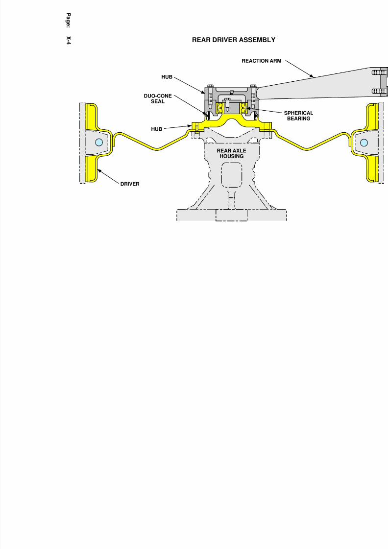
DRIVER
DUO-CONESEAL
HUB
SPHERICALBEARING
HUB
REACTION ARM
REAR DRIVER ASSEMBLY
REAR AXLEHOUSING

7/15/2019 Track
http://slidepdf.com/reader/full/track-5633844280401 6/16
X - 5
P age:

7/15/2019 Track
http://slidepdf.com/reader/full/track-5633844280401 7/16
CHAPTER : Undercarriage
CHALLENGER 35 & 45
X-6Page:

7/15/2019 Track
http://slidepdf.com/reader/full/track-5633844280401 8/16
CHAPTER : Undercarriage
CHALLENGER 35 & 45
X-7Page:
Available Belt Widths
GAUGE AND BELT COMBINATIONS
Spacer Length
(each)
Desired Gauge
Spacing
NoSpacers
25.4 mm(1 in.)
50.8 mm(2 in.)
76.2 mm
(3 in.)
101.6 mm(4 in.)
150.6 mm(6 in.)
203.2 mm(8 in.)
254 mm(10 in.)
355.6 mm(14 in.)
406, 457 mm (16, 18 in.)
406, 457, 508 mm (16, 18, 20 in.)
406, 457, 508 mm (16, 18, 20 in.)
406, 457, 508 mm (16, 18, 20 in.)
406, 457, 508. 635 mm (16, 18, 20, 25 in.)
406, 457, 508. 635 mm (16, 18, 20, 25 in.)
406, 457, 508. 635, 813 mm (16, 18, 20, 25, 32 in.)
406, 457, 508. 635, 813 mm (16, 18, 20, 25, 32 in.)
406, 457, 508. 635, 813 mm (16, 18, 20, 25, 32 in.)
1524 mm(60 in.)
1575 mm(62 in.)
1626 mm(64 in.)
1676 mm
(66 in.)
1727 mm(68 in.)
1828 mm(72 in.)
1930 mm(76 in.)
2032 mm(80 in.)
2235 mm(88 in.)

7/15/2019 Track
http://slidepdf.com/reader/full/track-5633844280401 9/16
CHAPTER : Undercarriage
CHALLENGER 35 & 45
X-8Page:
ADJUSTMENTS
UndercarriageAdjustments and
Procedures
Procedure to Detension
and Tension the Track
Detensioning
Adjustments and procedures to the undercarriage include:
• Procedure to detension and tension the track
• Procedure to check nitrogen charge (when adjusting track
tension) - SM 29/July/96
• Procedure to raise and lower the tractor
• Adjustment procedures to align the belts - SM 18/March/96
• Procedure to remove the undercarriage (change tractor
gauge) - SI, SEHS9982 (8/96) - Appendix
1. Connect one end of the charging hose assembly to the left "+"
implement coupler port of the No. 3 or No. 4 implement con-
trol valve and the other end to the quick disconnect fitting on
the manifold assembly. If the charging hose assembly cannot
be connected to the quick disconnect, see the topic titled
"Release of Residual Pressure."
To check the current charge pressure, first close the valve on
the charging hose. Open the charging valve (requires a 13
mm wrench) on the manifold assembly and read the gauge.
The charging valve is the valve under the guard. The charge
pressure should be 19000 kPa (2750 psi).
2. Place the No. 3 or No. 4 implement control lever (depending
how the tractor is equipped) for the port selected in the
FLOAT position.
3. Open the charging valve (if not already open) and the charging
hose valve to release the tension charge pressure into the
implement hydraulic system.
4. As the tension charge pressure is released, the front idlers will
pivot rearward and the belt will sag. Push the idlers rearward
to finish retracting the ram.
5. Close the charging valve and remove the charging hose assem-
bly.

7/15/2019 Track
http://slidepdf.com/reader/full/track-5633844280401 10/16
CHAPTER : Undercarriage
CHALLENGER 35 & 45
X-9Page:
ADJUSTMENTS
Maintenance Recharge
Tensioning (Unopened
System)
Release of Residual
Pressure
1. Verify that the charging valve is closed.
2. Connect one end of the charging hose assembly to the left "+"
implement coupler port of the No. 3 or No. 4 implement con-
trol valve and the other end to the quick disconnect fitting on
the manifold assembly. If the charging hose assembly cannot
be connected to the quick disconnect, see the topic titled
"Release of Residual Pressure."
3. Start the engine and run at low idle. Place and hold the No. 3
or No. 4 implement control lever (depending how the tractor is
equipped) in the RAISE position.
4. With the charging valve open 1/4 to 1 full turn maximum, wait
a minimum of 50 seconds for the hydraulic ram to fully
charge.
5. Close the charging hose valve first. Continue holding the
implement control lever in the RAISE position.
Read the gauge to verify the tension charge pressure. The
charge pressure should be 19000 kPa (2750 psi).
6. If the charge pressure is correct, close the charging valve and
open the charging hose valve.
7. Shut off the engine and place the implement control lever in
the FLOAT position. Remove the charging hose assembly.
If difficulty is encountered when connecting the charging hose to the
quick disconnect fitting, the resistance may be due to hydraulic pres-
sure behind the quick disconnect nipple. The pressure can be safely
relieved by using the following procedure:
1. Verify that the charging valve (3) is closed.
2. Using an 11/16 in. wrench, loosen the quick disconnect fitting
(1) 1/2 to 3/4 of a turn. DO NOT loosen beyond 3/4 of a turn.
A few drops of oil may leak out at the base along as the pres-
sure is relieved. If a significant amount of oil leaks or sprays
out, tighten the coupler immediately. The hand valve may be
malfunctioning and the hydraulic ram can only be safelydetensioned through the use of the bleeder screw.

7/15/2019 Track
http://slidepdf.com/reader/full/track-5633844280401 11/16
CHAPTER : Undercarriage
CHALLENGER 35 & 45
X-10Page:
ADJUSTMENTS
Check nitrogen Chargein Accumulator when
Adjusting Track
Tension
NOTE :
Check the dry nitrogen gas charge in the accumulator each time thetract tensioner group is adjusted. Use the same tooling used to adjust
the track (not the nitrogen charging group). Use the following proce-
dure for adjustment.
1. Charge the tensioner group to a minimum of 17 200 kPa (2500
psi) using 1U9058 Hose Group, then close the gate valve. Stop the
engine and place the control lever in the FLOAT position.
2. Open the gate valve enough to slowly relieve the tensioner
pressure. The gauge pressure should steadily decrease from 17 200
kpa (2500 psi) until a rapid drop in pressure occurs. Record the pres-
sure at which the rapid drop occurred and the resulting pressure
immediately after the rapid pressure drop. Close the gate valve.
The pressure at which the rapid drop occurs is the approximate
dry nitrogen precharge of the accumulator. The rapid pressure drop
should occur between 10 000 and 12 000 kPa (1450 and 1750 psi)
and drop rapidly at the maximum of 1400 kPa (200 psi). If the range
of the rapid pressure drop exceeds 1400 kPa (200 psi), the pressure
was bled too quickly. An inaccurate pressure reading result. Recharge
and re-bleed the tensioner group to obtain a better reading. The slow-
er the bleed rate, the more accurate the pressure measurement will be.
4. If the rapid pressure drop occurs below 10 000 Kpa (1450 psi)
or does not occur at all, the accumulator requires service or replace-
ment.
Do not operate the machine with an accumulator that has an inade-
quate nitrogen charge. The accumulator functions as a spring for the
undercarriage to recoil.
Machine operation with and inadequate nitrogen charge could result
in undercarriage damage and/or steering difficulty.

7/15/2019 Track
http://slidepdf.com/reader/full/track-5633844280401 12/16
CHAPTER : Undercarriage
CHALLENGER 35 & 45
X-11Page:
ADJUSTMENTS
Procedure to Raise andLower the Tractor
NOTE:
1. Raise the front of the tractor by placing a jack under the centerof the hardbar. Lift the tractor until approximately 102 mm (4
in.) of clearance exists between the belt treadbars and the
ground. Place stands under the flat support surfaces provided
on each of the frame rails. Lower the jack until the flats rest
on the stands. Remove the jack.
2. Raise the rear of the tractor by placing a jack under the center
of the swinging hardbar, directly behind the front pivot brack-
et. Lift the tractor until approximately 102 mm (4 in.) of
clearance exists between the belt treadbars and the floor.Place stands under each side of the drawbar cage. Lower the
jack until the cage rests on the stands. Remove the jack.
3. Check the stability of the support system by trying to manual-
ly shake the tractor. Do not continue with any procedure until
satisfied that the tractor is secure.
Reverse the procedure to lower the tractor.
If the belts must be removed, approximately 204 mm (8 in.) of clear-
ance will be needed.

7/15/2019 Track
http://slidepdf.com/reader/full/track-5633844280401 13/16
CHAPTER : Undercarriage
CHALLENGER 35 & 45
X-12Page:
ADJUSTMENTS
New Track AlignmentProcedure
Procedure #1
• Alignment Check
• Adjust Track Alignment
NOTE :
This Procedure replaces the current procedure found in the Operation
& Maintenance Manual.
1. Travel on a smooth and level surface for 61-91 m (200-300 ft)
at a speed less than 8 km?h (5 mph) without turning the steeringwheel. Allow the tractor to coast to a stop.
2. Apply the parking brake. Stop the engine. Block the front and
rear of the track.
3. Measure the clearance between the inside edges of the front
midwheel and the sides of the guide-blocks. If these distances agree
withing 2 mm (.080 in), the track is aligned correctly. Otherwise, use
the following procedure to adjust the alignment.
1. To cause the guide-blocks to ride closer to the outside mid-
wheels, first loosen outside locknut and turn screw counterclockwise
1/4 turn. Loosen the opposite side locknut and tighten the correspond-
ing set screw to a torque of 55±10 Nm (40±7 lb ft).
2. To cause the guide-blocks to ride closer to the inside midwheel,
loosen the inside locknut and turn the setscrew counterclockwise 1/4turn. Loosen the opposite side locknut and tighten the corresponding
set screw to a torque of 55±10 Nm (40±7 lb ft).
Do not adjust the setscrews more than 1/4 turn at a time.
3. Repeat the Checking Track Alignment procedures. If needed,
repeat Steps 1 and 2 above until guide-blocks are properly centered.
4. Tighten both locknuts to a torque of 136±15 Nm (100±11 lb
ft).Hold the setscrews when tightening the locknuts to prevent over-tightening the set screws.

7/15/2019 Track
http://slidepdf.com/reader/full/track-5633844280401 14/16
CHAPTER : Undercarriage
CHALLENGER 35 & 45
X-13Page:
ADJUSTMENTS
Procedure #2
• Alignment Check
• Adjust Track Alignment
NOTE :
1. After belt/track tension has been applied drive the machine on a
level paved road with as little steering as possible for approximately
15 to 18 minutes.
2. Stop the machine. Immediately record the maximum tempera-
ture of the inboard and outboard idler (inner) side walls. If the tem-
perature difference between the inboard and outboard idler is 22 deg.
C (40 deg. F) or more, proceed to step 3. If the temperature differ-
ence between the inboard and outboard idler is less than 22 deg. C(40 deg. F) belt/track is in alignment.
1. If the outer idler is the hottest, then loosen locknuts and back
inside setscrew out (counterclockwise) 1/4 turn. Turn outside screw in
(clockwise) 1/4 turn. If the inner idler is the hottest then loosen lock-
nuts and back outside setscrew out (counterclockwise) 1/4 turn. Turn
inside setscrew in (clockwise) 1/4 turn.
2. Tighten both setscrews to a torque of 55±10 Nm (40±7 lb ft).
Tighten locknuts to a torque of 136±15 Nm (100±11 lb ft).
Do not adjust the setscrews more than 1/4 turn at a time.

7/15/2019 Track
http://slidepdf.com/reader/full/track-5633844280401 15/16
CHAPTER : Undercarriage
CHALLENGER 35 & 45
X-14Page:
ADJUSTMENTS

7/15/2019 Track
http://slidepdf.com/reader/full/track-5633844280401 16/16
CHAPTER : Undercarriage
CHALLENGER 35 & 45
ADJUSTMENTS


