30
Traffic Control Systems - SCOOT/UTC ATD 98/07 -Transp.-Nr.: 1 / 00 Ord.-Nr.: SCOOT TRB Presentation on SCOOT January 2000
| Date post: | 18-Jan-2016 |
| Category: |
Documents |
| Upload: | polly-ella-joseph |
| View: | 250 times |
| Download: | 4 times |
Traffic Control Systems - SCOOT/UTC ATD 98/07 -Transp.-Nr.: 1 / 00Ord.-Nr.:
SCOOT
TRB Presentation on SCOOT
January 2000
Traffic Control Systems - SCOOT/UTC ATD 98/07 -Transp.-Nr.: 2 / 00Ord.-Nr.:
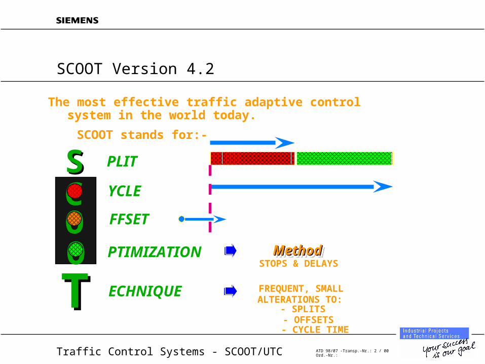
SCOOT Version 4.2
MethodMethodMethodMethod
ALTERATIONS TO:- SPLITS- OFFSETS- CYCLE TIME
FREQUENT, SMALL
STOPS & DELAYS
SCOOT stands for:-SCOOT stands for:-
The most effective traffic adaptive controlThe most effective traffic adaptive controlsystem in the world today.system in the world today.
PLITSSYCLECFFSETO
O PTIMIZATION
TT ECHNIQUE
Traffic Control Systems - SCOOT/UTC ATD 98/07 -Transp.-Nr.: 3 / 00Ord.-Nr.:
System Architecture
• Second by second system, with timing algorithms in central processor
• Local controller deals with clearance and minimums
• Local vehicle actuation determined by traffic engineering priorities
• Heirarchical transmission system with flexibility to suit local traffic control needs
Traffic Control Systems - SCOOT/UTC ATD 98/07 -Transp.-Nr.: 4 / 00Ord.-Nr.:
SCOOT Principles
• Detector processing
• Cyclic flow profiles
• Traffic model
• Optimisers
Traffic Control Systems - SCOOT/UTC ATD 98/07 -Transp.-Nr.: 5 / 00Ord.-Nr.:
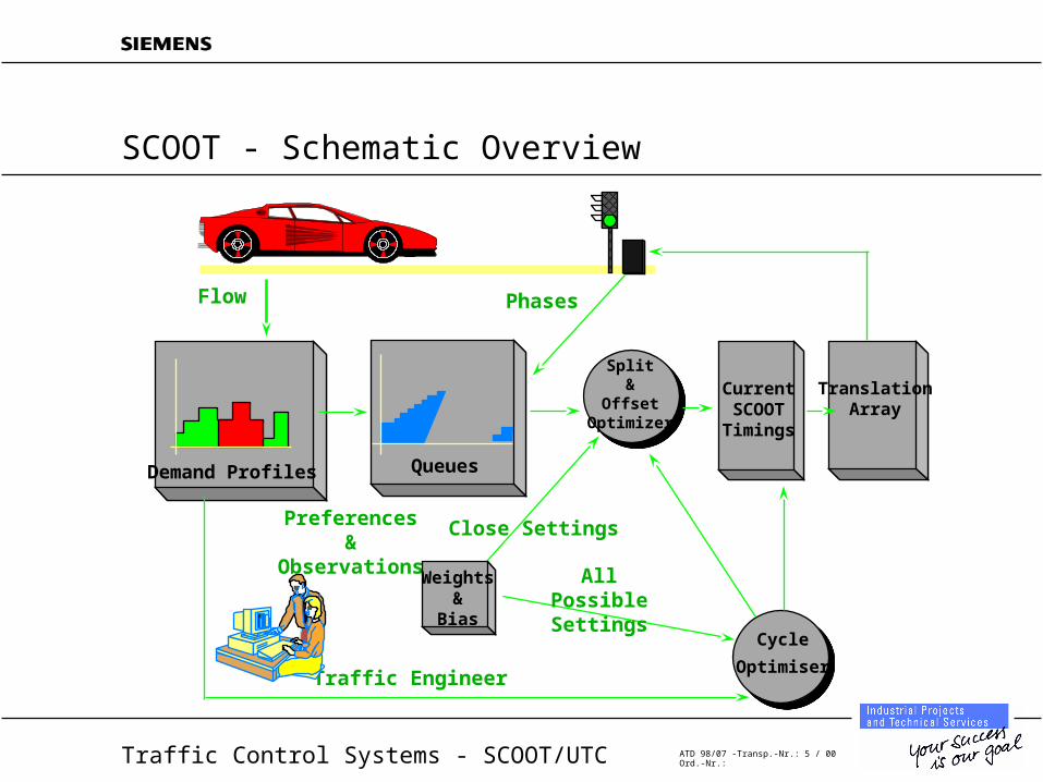
SCOOT - Schematic Overview
PhasesFlow
Demand Profiles Queues
Split&
OffsetOptimizer
Traffic Engineer
Preferences&
ObservationsWeights
&Bias
Cycle
Optimiser
Close Settings
All Possible Settings
CurrentSCOOTTimings
TranslationArray
Traffic Control Systems - SCOOT/UTC ATD 98/07 -Transp.-Nr.: 6 / 00Ord.-Nr.:
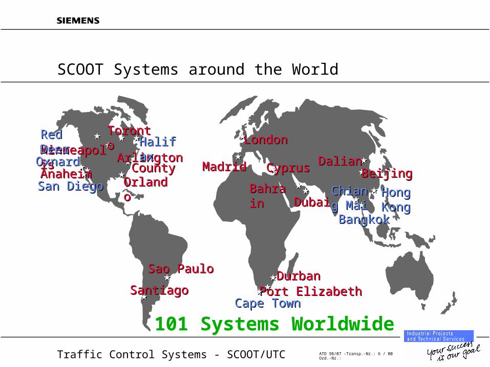
SCOOT Systems around the World
TorontoToronto
CyprusCyprusMadridMadrid
LondonLondon
AnaheimAnaheim
SantiagoSantiago
Sao PauloSao Paulo
BahrainBahrain Hong KongHong Kong
DalianDalian
DurbanDurbanPort ElizabethPort Elizabeth
DubaiDubai
Arlington Arlington CountyCounty
101 Systems Worldwide
MinneapolisMinneapolisOxnardOxnard
San DiegoSan Diego
Red DeerRed DeerHalifaxHalifax
Cape TownCape Town
BangkokBangkok
Chiang Chiang MaiMai
BeijingBeijingOrlandoOrlando
Traffic Control Systems - SCOOT/UTC ATD 98/07 -Transp.-Nr.: 7 / 00Ord.-Nr.:
SCOOT - Where will it work?
• SCOOT works on both Arterial Streets and Grid Networks– Arterial streets - examples
» Toronto - Lake Shore Boulevard
» London - Cromwell Road
» Oxnard, Ca
» Sao Paulo - Rio Branco
– Networks - examples» Toronto - CBD
» Dubai
» London - West End
» Madrid - Central area
• SCOOT works on networks from <10 intersections to >1000– Cambridge (UK) - 9 nodes initially
– Sao Paulo (Brazil) >1000 nodes
Traffic Control Systems - SCOOT/UTC ATD 98/07 -Transp.-Nr.: 8 / 00Ord.-Nr.:
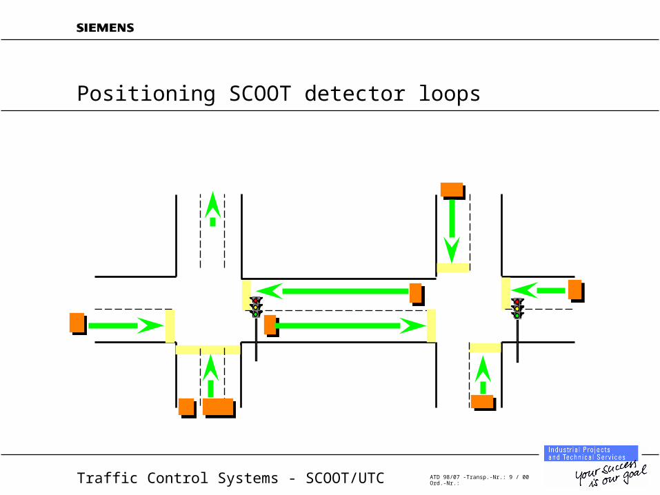
Data Requirements
• Detection on every link for which full optimization required
• Detectors generally located at upstream end of link
• Connection to central computer achieved via upstream intersection
• Links with no detection run fixed length or can have data derived from upstream links
– Fixed length phases can be varied by time of day
Traffic Control Systems - SCOOT/UTC ATD 98/07 -Transp.-Nr.: 9 / 00Ord.-Nr.:
Positioning SCOOT detector loops
Traffic Control Systems - SCOOT/UTC ATD 98/07 -Transp.-Nr.: 10 / 00Ord.-Nr.:
Communication
• Dedicated multi-drop transmission lines to outstations
• Second by second communications to and from outstation
• Typically six to eight intersections / drop @ 1200 Baud
Traffic Control Systems - SCOOT/UTC ATD 98/07 -Transp.-Nr.: 11 / 00Ord.-Nr.:
Control Variables
• modelling uses measured vehicle demand (occupancy) and calculated queue length
• optimization uses demand (flow profiles) and calculated delay/saturation
• approach is to make small, regular changes to timings to minimize transients
• seven primary validation parameters (to correlate internal traffic model with the real world)
• dozens of parameters to allow the traffic engineer to tune system performance
– a full library of default values is provided
– these are changeable by time-of-day, or manually
Traffic Control Systems - SCOOT/UTC ATD 98/07 -Transp.-Nr.: 12 / 00Ord.-Nr.:
Data Sampling, Filtering and Smoothing
• Detection based on vehicle occupancy
• Detector is typically a loop, with length 2m in direction of travel
• Sampling rate is 0.25s
• Algorithm processes raw data into LPUs based on linear discounting
• Demand profile for each link is built up in four second increments
• Controller phase replies used to enhance modelling
Traffic Control Systems - SCOOT/UTC ATD 98/07 -Transp.-Nr.: 13 / 00Ord.-Nr.:
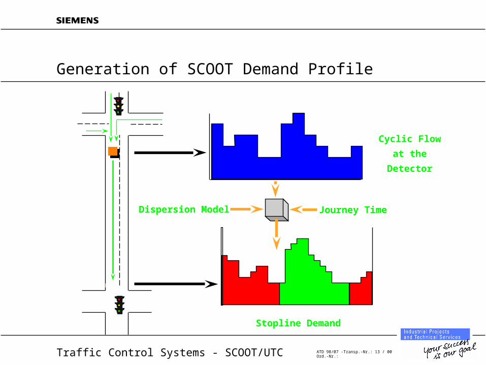
Generation of SCOOT Demand Profile
Stopline Demand
Cyclic Flow
at the
Detector
Journey TimeDispersion Model
Traffic Control Systems - SCOOT/UTC ATD 98/07 -Transp.-Nr.: 14 / 00Ord.-Nr.:
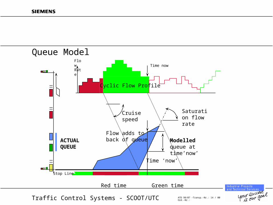
Red time Green time
Time nowFlow Rate
Stop Line
Saturation flow rate
Flow adds to back of queue
Time ‘now’
Modelled queue at time’now’
ACTUALQUEUE
Cruisespeed
Cyclic Flow Profile
Queue Model
Traffic Control Systems - SCOOT/UTC ATD 98/07 -Transp.-Nr.: 15 / 00Ord.-Nr.:
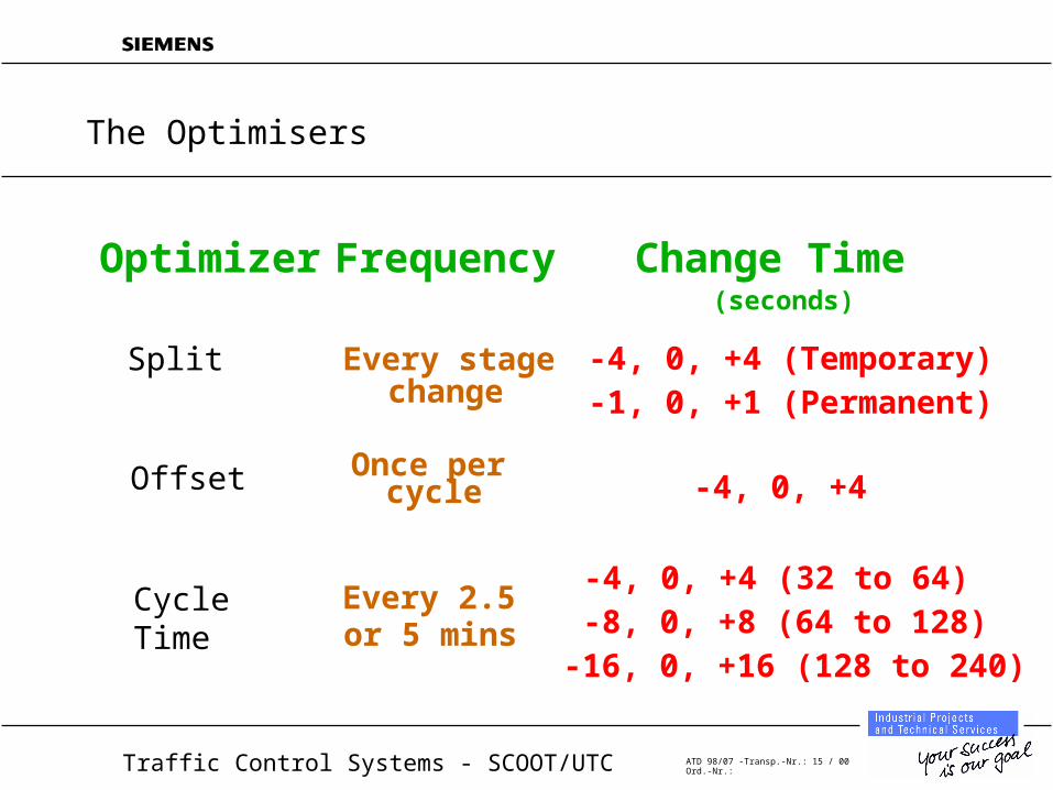
(seconds)
Optimizer Frequency
Split Every stagechange
-4, 0, +4 (Temporary)
Offset Once percycle -4, 0, +4
Cycle Time
Every 2.5or 5 mins
Change Time
-1, 0, +1 (Permanent)
-4, 0, +4 (32 to 64)-8, 0, +8 (64 to 128)
-16, 0, +16 (128 to 240)
The Optimisers
Traffic Control Systems - SCOOT/UTC ATD 98/07 -Transp.-Nr.: 16 / 00Ord.-Nr.:
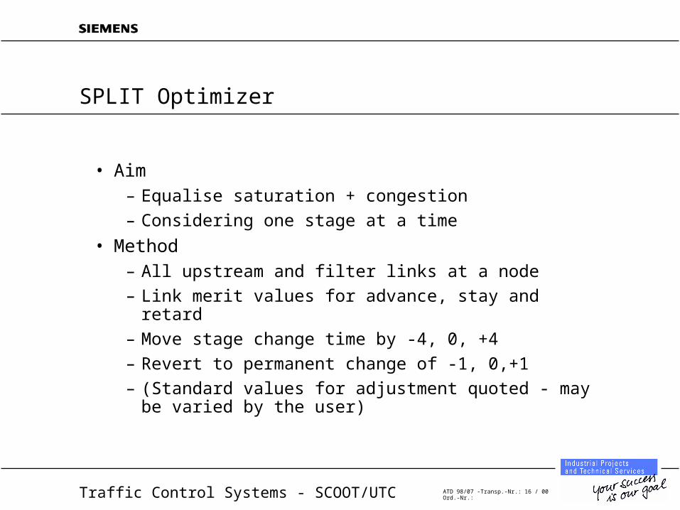
SPLIT Optimizer
• Aim– Equalise saturation + congestion
– Considering one stage at a time
• Method– All upstream and filter links at a node
– Link merit values for advance, stay and retard
– Move stage change time by -4, 0, +4
– Revert to permanent change of -1, 0,+1
– (Standard values for adjustment quoted - may be varied by the user)
Traffic Control Systems - SCOOT/UTC ATD 98/07 -Transp.-Nr.: 17 / 00Ord.-Nr.:
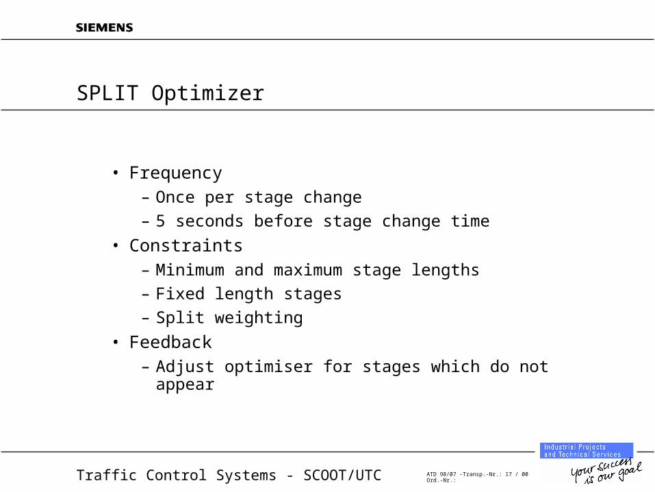
SPLIT Optimizer
• Frequency– Once per stage change
– 5 seconds before stage change time
• Constraints– Minimum and maximum stage lengths
– Fixed length stages
– Split weighting
• Feedback– Adjust optimiser for stages which do not appear
Traffic Control Systems - SCOOT/UTC ATD 98/07 -Transp.-Nr.: 18 / 00Ord.-Nr.:
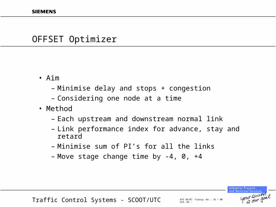
OFFSET Optimizer
• Aim– Minimise delay and stops + congestion
– Considering one node at a time
• Method– Each upstream and downstream normal link
– Link performance index for advance, stay and retard
– Minimise sum of PI’s for all the links
– Move stage change time by -4, 0, +4
Traffic Control Systems - SCOOT/UTC ATD 98/07 -Transp.-Nr.: 19 / 00Ord.-Nr.:
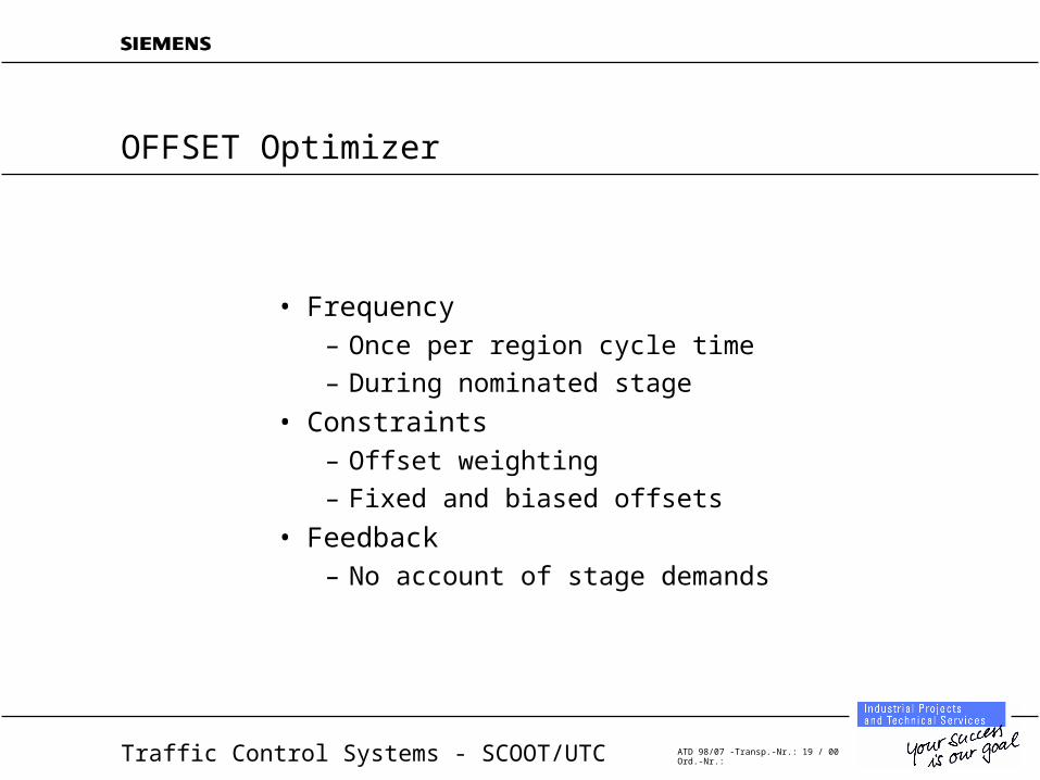
OFFSET Optimizer
• Frequency– Once per region cycle time
– During nominated stage
• Constraints– Offset weighting
– Fixed and biased offsets
• Feedback– No account of stage demands
Traffic Control Systems - SCOOT/UTC ATD 98/07 -Transp.-Nr.: 20 / 00Ord.-Nr.:
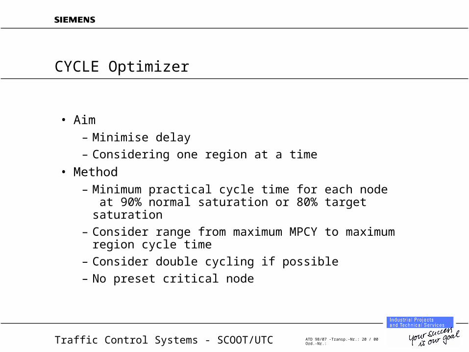
CYCLE Optimizer
• Aim– Minimise delay
– Considering one region at a time
• Method– Minimum practical cycle time for each node at 90% normal
saturation or 80% target saturation
– Consider range from maximum MPCY to maximum region cycle time
– Consider double cycling if possible
– No preset critical node
Traffic Control Systems - SCOOT/UTC ATD 98/07 -Transp.-Nr.: 21 / 00Ord.-Nr.:
CYCLE Optimizer
• Frequency– Usually every 5 minutes
– Every 2.5 minutes when cycle rising
– Every 2.5 minutes when cycle is falling (if required)
• Constraints– Maximum region cycle time
– MPCY’s of nodes
– Minimum node cycle time
– Forced single cycle or forced double cycle (if possible)
• Feedback– Stage demands taken into account
Traffic Control Systems - SCOOT/UTC ATD 98/07 -Transp.-Nr.: 22 / 00Ord.-Nr.:
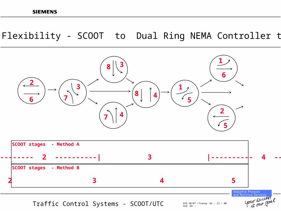
SCOOT stages - Method A
1 |--------- 2 ----------| 3 |---------- 4 -----------|
2
8
47
3
76
148
3
6
5
2
1
5
Phasing Flexibility - SCOOT to Dual Ring NEMA Controller translation
SCOOT stages - Method B
1 2 3 4 5 6
Traffic Control Systems - SCOOT/UTC ATD 98/07 -Transp.-Nr.: 23 / 00Ord.-Nr.:
Measures of effectiveness
• Optimization targetted in general at minimising delay– User specifies relative importance of stops and delay
• Split at a node balances degree of saturation on adjacent links– subject to weighting parameters from the local traffic engineer
• Offset determined by node performance index– choose best offset to minimise stops and delays on all
adjacent links
• Cycle time maintains all links at no more than 90% saturation
Traffic Control Systems - SCOOT/UTC ATD 98/07 -Transp.-Nr.: 24 / 00Ord.-Nr.:
MOE’s
• Data from SCOOT to demonstrate how it is achieving the above targets?
• “Event Driven messages” from SCOOT M02 / M03 / M04» 02 = link
» 03 = node
» 04 = region
– Stops ( vehicle.stops / hour )
– Delay ( vehicle.hour / hour )
– Flow ( vehicle / hour )
– Congestion ( intervals / hour )
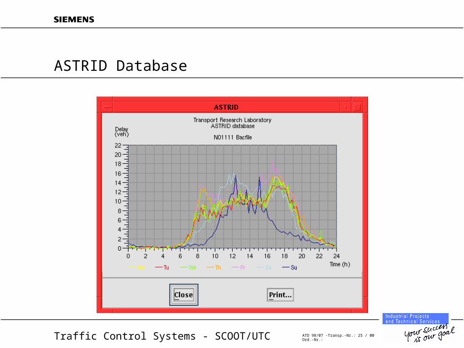
• All this data can be processed by ASTRID
Traffic Control Systems - SCOOT/UTC ATD 98/07 -Transp.-Nr.: 25 / 00Ord.-Nr.:
ASTRID Database
Traffic Control Systems - SCOOT/UTC ATD 98/07 -Transp.-Nr.: 26 / 00Ord.-Nr.:
Transit Priority
• Transit priority is a standard feature within SCOOT V3.1
• Dealt with by optimizing the priority provision– Extensions to running stage
– Recall on minima via normal stage sequence to bus stage
– Recovery to previous offset as quickly as possible
– AVL and loop detection
Traffic Control Systems - SCOOT/UTC ATD 98/07 -Transp.-Nr.: 27 / 00Ord.-Nr.:
Fire Priority
• Fire priority is a standard feature within the SCOOT system
• Optimization suspended during absolute priority, but modelling continues
– Fast recovery to normal conditions at end of priority period
• V4.2 has recovery algorithms (not the same as bus priority)
Traffic Control Systems - SCOOT/UTC ATD 98/07 -Transp.-Nr.: 28 / 00Ord.-Nr.:
Special Features for Oversaturated Conditions
• Congestion importance factors / congestion offset per link
• Congestion links with congestion importance factors
• Gating
• Variable Node Based Target Saturation for cycle time optimisation
Traffic Control Systems - SCOOT/UTC ATD 98/07 -Transp.-Nr.: 29 / 00Ord.-Nr.:
Congestion Importance Factors / Congestion Offset
• Congestion Importance Factor is specified for each link– Used to influence Split calculations in favour of the link, when
congestion is detected
• Congestion Offset is a fixed offset, specified by the Traffic Engineer, to be used in congested conditions
– Congestion Weighting Factor allows the engineer to specify the importance of achieving the Congestion Offset
Traffic Control Systems - SCOOT/UTC ATD 98/07 -Transp.-Nr.: 30 / 00Ord.-Nr.:
Other Features
• SOFT (on-line calibration of sat. flow)
• Use of alternative existing detection (although some reduced efficiency results)
• Variable authorities (i.e. variable bounds on optimiser decisions)
• Flared approaches (V4.2)


