86
Traffic Modelling Guidelines: SIDRA Intersection VERSION 2.0 PUBLISHED AUGUST 2021
Traffic Modelling Guidelines:
SIDRA Intersection
VERSION 2.0 PUBLISHED AUGUST 2021
Traffic Modelling Guidelines – SIDRA INTERSECTION
Knet #12035709 UNCONTROLLED COPY WHEN PRINTED Version Number 2.0 Issue Date: August 2021 Document Owner: Manager Traffic Integrity Page 2 of 81
Department for Infrastructure and Transport
Traffic Modelling Guidelines – SIDRA INTERSECTION
First Published November 2017.
Version 2.0 August 2021.
Disclaimer
The application of this manual does not guarantee that the resulting SIDRA Intersection traffic analysis models shall be ‘fit-for-purpose’. This manual only provides a framework for model development, calibration and validation. Some models, particularly models to be used for financial analysis will require more stringent standards and it is the responsibility of the designer to ensure that the models they develop are fit for their intended purpose.
This document should only be considered relevant in South Australia and for no other purpose than as a guide for designers undertaking work for the Department for Infrastructure and Transport (the Department).
The Department and the authors of this manual accept no liability or responsibility for any errors or omission, or for any damage or loss arising from the application of the information provided.
All trade name references in this manual are either trademarks or registered trademarks of their respective companies.
The Guidelines are approved for use by the Department staff and the departments’ agents.
Endorsed…………………………………………….Julian Yii,
Team Leader Traffic Congestion Reduction, Network Management Services.
31/08/2021
Approved……………………………………….......Jasmina Jovanovic,
Manager Traffic Integrity, Network Management Services.
31/08/2021
For errors and omissions contact:
Julian Yii ([email protected]) or
John Buckland ([email protected])
Network Management Services Directorate
Department for Infrastructure and Transport
GPO Box 1533 Adelaide SA 5001
Traffic Modelling Guidelines – SIDRA INTERSECTION
Knet #12035709 UNCONTROLLED COPY WHEN PRINTED Version Number 2.0 Issue Date: August 2021 Document Owner: Manager Traffic Integrity Page 3 of 81
Revisions Revisions to the document will be made from time to time. Revisions will only be published on the Department home page (https://dit.sa.gov.au/documents).
It shall be the responsibility of the users of this document to ensure that the most current version is followed.
VERSION MONTH/YEAR DESCRIPTION OF REVISION APPROVED BY
1.0 November 2017 Original publication
2.0 August 2021 SIDRA Version 9 update
Traffic Modelling Guidelines – SIDRA INTERSECTION
Knet #12035709 UNCONTROLLED COPY WHEN PRINTED Version Number 2.0 Issue Date: August 2021 Document Owner: Manager Traffic Integrity Page 4 of 81
Department for Infrastructure and Transport Traffic Modelling Guidelines -
SIDRA INTERSECTION Table of Contents
LIST OF TABLES ............................................................................................................. 6 LIST OF FIGURES ........................................................................................................... 7
1 INTRODUCTION .......................................................................................................... 8 1.1 The Role of SIDRA in Transport Modelling Analysis ............................................ 9 1.2 Model Description .................................................................................................. 9
2 MODEL CHARACTERISTICS ................................................................................... 11 2.1 Intersection Familiarisation.................................................................................. 11 2.2 Model Periods ...................................................................................................... 11 2.3 Data Collection .................................................................................................... 11 2.4 SCATS® Summaries Data ................................................................................... 11 2.5 Non-Green (Yellow / Red) Time .......................................................................... 12 2.6 Saturation Flow and SCATS® Maximum Flow [MF] ........................................... 12 2.7 SCATS® Signal Timing Data................................................................................ 12 2.8 Queue Lengths .................................................................................................... 13 2.9 Traffic Volume Data and Classification Data ...................................................... 13
3 MODEL DEVELOPMENT .......................................................................................... 14 3.1 Model Scoping Document ................................................................................... 14 3.2 Stages of Model Development ............................................................................ 14 3.3 Base Case Model ................................................................................................ 14
3.3.1 Calibration ..................................................................................................... 15 3.3.2 Validation ...................................................................................................... 16
3.4 Interim Model Processing - Traffic Signals ......................................................... 17 3.5 Base Case for Comparison ................................................................................. 18 3.6 Future Year Model ............................................................................................... 18 3.7 Projected Scenarios ............................................................................................ 19
3.7.1 Development Applications and Traffic Generation ...................................... 19 3.7.2 Future Year Traffic Projections .................................................................... 20 3.7.3 DPTI Standard Traffic Signal Conventions. ................................................. 20 3.7.4 Design of Minimum Phase Times and Intergreen Periods .......................... 20
3.8 Measures of Performance ................................................................................... 21 3.8.1 Degree of Saturation (DoS) .......................................................................... 21 3.8.2 95th Percentile Back of Queue Distance ..................................................... 21 3.8.3 Level of Service (LoS) .................................................................................. 21 3.8.4 Delays and Stops ......................................................................................... 22
3.9 Model Reporting Requirements .......................................................................... 22 4 MODEL CONSTRUCTION - TRAFFIC SIGNALS ..................................................... 23
4.1 Getting Started – Configuration for the Base Case ............................................ 23 4.1.1 Site Tab ......................................................................................................... 23 4.1.2 Settings ......................................................................................................... 24 4.1.3 Site Input Data .............................................................................................. 25 4.1.4 Intersection Dialogue .................................................................................... 26 4.1.5 Project File Naming Conventions ................................................................. 27 4.1.6 Parameter setting dialogue .......................................................................... 27
Traffic Modelling Guidelines – SIDRA INTERSECTION
Knet #12035709 UNCONTROLLED COPY WHEN PRINTED Version Number 2.0 Issue Date: August 2021 Document Owner: Manager Traffic Integrity Page 5 of 81
4.1.7 Demand and Sensitivity Dialogue ................................................................ 30 4.1.8 Movement Definitions ................................................................................... 31 4.1.9 Vehicle Movement Data ............................................................................... 33 4.1.10 Lane Geometry Dialogue ...................................................................... 36 4.1.11 Lane Configuration ................................................................................ 37 4.1.12 Lane Disciplines .................................................................................... 39 4.1.13 Lane Data .............................................................................................. 41 4.1.14 Lane Movements ................................................................................... 43 4.1.15 Volumes Dialogue ................................................................................. 44 4.1.16 Vehicle Volumes .................................................................................... 44 4.1.17 Volume Factors ..................................................................................... 45 4.1.18 Pedestrians ............................................................................................ 46 4.1.19 Pedestrian Movement ........................................................................... 46 4.1.20 Pedestrian Movement Data................................................................... 47 4.1.21 Pedestrian Timing Data ......................................................................... 48 4.1.22 Phasing & Timing Dialogue ................................................................... 49 4.1.23 Phase Sequences ................................................................................. 50 4.1.24 Phase Sequence Editor......................................................................... 51 4.1.25 Phase & Sequence Data ....................................................................... 52 4.1.26 Timing Options ...................................................................................... 54 4.1.27 Priorities Dialogue ................................................................................. 56 4.1.28 Gap-Acceptance .................................................................................... 57 4.1.29 Gap-Acceptance Data ........................................................................... 57 4.1.30 Settings .................................................................................................. 58
4.2 Proposed Scenario Models ................................................................................. 59 4.2.1 Proposed Geometric Changes ..................................................................... 59 4.2.2 Proposed Phase Arrangements ................................................................... 59 4.2.3 Future Year Traffic Volumes ........................................................................ 61
5 MODEL CONSTRUCTION ROUNDABOUTS AND SIGN CONTROL INTERSECTIONS.............................................................................................................. 62
5.1 ROUNDABOUTS ................................................................................................. 62 5.1.1 Intersection (Roundabout) ............................................................................ 62 5.1.2 Roundabouts Dialogue ................................................................................. 63 5.1.3 Options (Roundabout) .................................................................................. 63 5.1.4 Roundabout Data ......................................................................................... 63 5.1.5 Gap Acceptance (Roundabout) ................................................................... 64 5.1.6 Gap Acceptance Data (Roundabout) ........................................................... 64 5.1.7 Lane Geometry (roundabout) ....................................................................... 65 5.1.8 Lane Configuration (Roundabout) ................................................................ 65
5.2 SIGN CONTROL - STOP OR GIVE WAY .......................................................... 66 5.2.1 Intersection (Sign Control) ........................................................................... 67 5.2.2 Sign Control .................................................................................................. 67 5.2.3 Gap Acceptance (Sign Control) ................................................................... 68 5.2.4 Gap Acceptance Data (Sign Control) .......................................................... 68 5.2.5 Two-Way Sign Control ................................................................................. 69 5.2.6 Gap Acceptance Settings ............................................................................. 70 5.2.7 Field Measurements and Calibration of Gap Acceptance ........................... 70 5.2.8 Staged Crossing – Special Parameter Settings .......................................... 71
6 MODEL REPORTS .................................................................................................... 72
Traffic Modelling Guidelines – SIDRA INTERSECTION
Knet #12035709 UNCONTROLLED COPY WHEN PRINTED Version Number 2.0 Issue Date: August 2021 Document Owner: Manager Traffic Integrity Page 6 of 81
6.1 Calibration Report ................................................................................................ 73 6.2 Validation Report ................................................................................................. 74 6.3 Scenario Models Report ...................................................................................... 74 6.4 Recommended Scenario ..................................................................................... 75
7 APPENDIX A - MODEL SCOPING DOCUMENT...................................................... 76 8 APPENDIX B - DATA COLLECTION ......................................................................... 77
8.1 Traffic Count Data ............................................................................................... 78 8.2 Typical Traffic Conditions .................................................................................... 79
9 APPENDIX C - QUICK GUIDE - Traffic Signals Configuration Checks.................... 81 10 APPENDIX D – SUPPORT SERVICES .................................................................... 82
10.1 SCATS® summaries ............................................................................................ 82 11 APPENDIX E - SOURCE MATERIAL ........................................................................ 85
LIST OF TABLES
Table 1 Suggested method for distinguishing optimiser effects ....................................... 18 Table 2 Maximum practical degree of saturation............................................................. 21 Table 3 PCU values for AUSTROADS classes ................................................................ 29 Table 4 Vehicle length for AUSTROADS classes ............................................................ 34 Table 5 Example of Basic Saturation Flow Calibration .................................................... 41 Table 6 Minimum Phase Green Time Relating to Pedestrian Frequency ....................... 53 Table 7 Maximum values for Extra Bunching (roundabout) ............................................. 62 Table 8 Maximum values for Extra Bunching (sign control) ............................................. 67
Traffic Modelling Guidelines – SIDRA INTERSECTION
Knet #12035709 UNCONTROLLED COPY WHEN PRINTED Version Number 2.0 Issue Date: August 2021 Document Owner: Manager Traffic Integrity Page 7 of 81
LIST OF FIGURES
Figure 1 "Detailed Output" Lane flow data ........................................................................ 16 Figure 2 Main Screen < Site tab dialogue......................................................................... 23 Figure 3 Main Screen < Manage ribbon dialogue. ........................................................... 24 Figure 4 Main Screen < Manage ribbon < Site Output < Volume Displays dialogue ...... 25 Figure 5 INTERSECTION < Intersection tab dialogue ..................................................... 26 Figure 6 PARAMETER SETTINGS < Options tab dialogue............................................. 28 Figure 7 PARAMETER SETTINGS < Model Parameters tab dialogue ........................... 29 Figure 8 PARAMETER SETTINGS < Advanced tab dialogue ......................................... 30 Figure 9 DEMAND & SENSITIVITY dialogue .................................................................. 31 Figure 10 MOVEMENT DEFINITIONS < Movement Classes tab dialogue..................... 31 Figure 11 MOVEMENT DEFINITIONS < Origin-Destination tab dialogue ...................... 32 Figure 12 VEHICLE MOVEMENT DATA < Path Data tab dialogue ................................ 33 Figure 13 VEHICLE MOVEMENT DATA < Calibration tab dialogue (Light Vehicles)..... 33 Figure 14 VEHICLE MOVEMENT DATA < Calibration tab dialogue (Heavy Vehicles) .. 34 Figure 15 VEHICLE MOVEMENT DATA < Signals tab dialogue..................................... 35 Figure 16 LANE GEOMETRY < Lane Configuration tab dialogue ................................... 37 Figure 17 Short Approach Lane Length Measurement .................................................... 38 Figure 18 Short Exit Lane Length Measurement .............................................................. 38 Figure 19 LANE GEOMETRY Dialogue < Lane Disciplines tab dialogue ....................... 39 Figure 20 LANE GEOMETRY < Lane Data Approach Lane tab dialogue ....................... 40 Figure 21 LANE GEOMETRY < Lane Data Exit Lane tab dialogue ................................ 40 Figure 22 LANE MOVEMENTS < Flow Proportions tab dialogue ................................... 43 Figure 23 LANE MOVEMENT < Blockage Calibration tab dialogue ................................ 43 Figure 24 VOLUMES < Vehicle Volumes tab dialogue .................................................... 44 Figure 25 VOLUMES < Vehicle Factors tab dialogue ...................................................... 45 Figure 26 PEDESTRIANS < Pedestrian Movements tab dialogue .................................. 46 Figure 27 PEDESTRIANS < Pedestrian Movements Data tab dialogue ......................... 47 Figure 28 PEDESTRIANS < Pedestrian Timing Data tab dialogue ................................. 48 Figure 29 PHASING & TIMING < Sequences tab dialogue ............................................. 50 Figure 30 PHASING & TIMING < Sequence Editor tab dialogue .................................... 51 Figure 31 PHASING & TIMING < Phase & Sequence Data tab dialogue ....................... 52 Figure 32 PHASING & TIMING < Timing Options tab dialogue ....................................... 54 Figure 33 PHASING & TIMING < Advanced tab dialogue ............................................... 55 Figure 34 PRIORITIES dialogue ....................................................................................... 56 Figure 35 GAP ACCEPTANCE < Gap Acceptance Data tab dialogue............................ 57 Figure 36 GAP ACCEPTANCE < Settings tab dialogue .................................................. 58 Figure 37 INTERSECTION < Intersection dialogue (roundabout) ................................... 62 Figure 38 ROUNDABOUTS < Options tab dialogue ........................................................ 63 Figure 39 ROUNDABOUTS < Roundabout Data tab dialogue ........................................ 63 Figure 40 GAP ACCEPTANCE < Gap Acceptance Data tab dialogue (roundabout) .... 64 Figure 41 LANE GEOMETRY < Lane Configuration tab dialogue (roundabout)............. 65 Figure 42 Site layout two-way stop sign control ............................................................... 66 Figure 43 INTERSECTION < Intersection tab dialogue (sign control) ............................. 67 Figure 44 GAP ACCEPTANCE < Gap Acceptance Data tab dialogue (sign control) ..... 68 Figure 46 GAP ACCEPTANCE < Two-Way Sign Control tab dialogue ........................... 69 Figure 47 Main Screen < Manage ribbon < Output customisation ................................... 72 Figure 48 Typical Vehicle Turning Movement Survey PDF format. ................................. 79
Traffic Modelling Guidelines – SIDRA INTERSECTION
Knet #12035709 UNCONTROLLED COPY WHEN PRINTED Version Number 2.0 Issue Date: August 2021 Document Owner: Manager Traffic Integrity Page 8 of 81
Department for Infrastructure and Transport Traffic Modelling Guidelines
SIDRA INTERSECTION
1 INTRODUCTION The Department for Infrastructure and Transport (the Department) is the State Government agency responsible for managing the strategic road network within South Australia. As part of this responsibility, the Department uses a range of traffic analysis tools to assess road network performance and to plan future development of the network.
The objectives of these guidelines are to:
Provide guidance to both the Department staff and those submitting work to the Department, on what are the acceptable input parameters, performance measures, calibration requirements and reporting structure in SIDRA Intersection (SIDRA) modelling.
Develop consistency in traffic modelling practice and promote high quality model outputs that will lead to high quality project design.
Ensure that all intersections are being modelled accurately.
These guidelines are not limited to the above list of requirements and the Department reserves the right to undertake further assessment with different criteria.
This document is designed to assist practitioners when building SIDRA models of intersections suitable for submitting development or project scenarios to the Department, for assessment/approval by the Network Management Services Directorate.
Network Management Services Directorate is responsible for managing the Department traffic signal assets and the provision of any information required for the design of traffic signals, and further references in this document to the Department imply the oversight of this Directorate.
Where the SIDRA modelling is being undertaken and there is a resulting modification to existing signals or a new signal installation is to be provided the traffic signals design is required to conform to the Traffic Signal Design Master Specification (RD-EL-D2) which requires a Traffic Signal Operations Performance Report (TSOPR) to be provided.
The Traffic Signal Design Master Specification is also available from the Department standards web site “technical standards and guidelines” https://dit.sa.gov.au/documents.
This guideline covers the broad areas of building, calibrating, validating and documenting SIDRA models and is to be used as the primary guide for the development of ‘fit-for-purpose’ SIDRA models for use within the Department.
SIDRA is a the Department approved software application to be used to justify traffic signal phasing, and phase sequences for individual traffic signal sites.
Model developers and SIDRA users need to have a high level of understanding of traffic operations, including SCATS®, and intersection modelling in order to achieve accurate models that are ‘fit-for-purpose’ and to ensure that the behavioural parameters remain within acceptable bounds.
A summary of the Department requirements in respect of a SIDRA model is contained in the appendices;
Traffic Modelling Guidelines – SIDRA INTERSECTION
Knet #12035709 UNCONTROLLED COPY WHEN PRINTED Version Number 2.0 Issue Date: August 2021 Document Owner: Manager Traffic Integrity Page 9 of 81
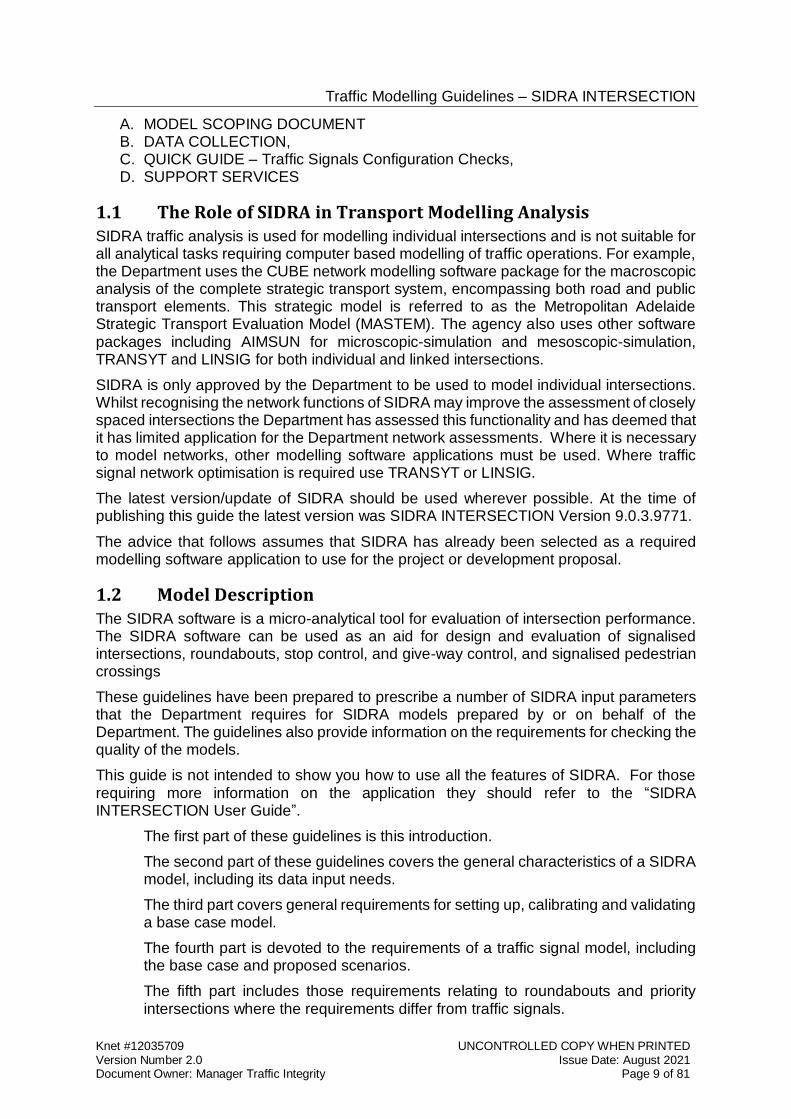
A. MODEL SCOPING DOCUMENT B. DATA COLLECTION, C. QUICK GUIDE – Traffic Signals Configuration Checks, D. SUPPORT SERVICES
1.1 The Role of SIDRA in Transport Modelling Analysis SIDRA traffic analysis is used for modelling individual intersections and is not suitable for all analytical tasks requiring computer based modelling of traffic operations. For example, the Department uses the CUBE network modelling software package for the macroscopic analysis of the complete strategic transport system, encompassing both road and public transport elements. This strategic model is referred to as the Metropolitan Adelaide Strategic Transport Evaluation Model (MASTEM). The agency also uses other software packages including AIMSUN for microscopic-simulation and mesoscopic-simulation, TRANSYT and LINSIG for both individual and linked intersections.
SIDRA is only approved by the Department to be used to model individual intersections. Whilst recognising the network functions of SIDRA may improve the assessment of closely spaced intersections the Department has assessed this functionality and has deemed that it has limited application for the Department network assessments. Where it is necessary to model networks, other modelling software applications must be used. Where traffic signal network optimisation is required use TRANSYT or LINSIG.
The latest version/update of SIDRA should be used wherever possible. At the time of publishing this guide the latest version was SIDRA INTERSECTION Version 9.0.3.9771.
The advice that follows assumes that SIDRA has already been selected as a required modelling software application to use for the project or development proposal.
1.2 Model Description The SIDRA software is a micro-analytical tool for evaluation of intersection performance. The SIDRA software can be used as an aid for design and evaluation of signalised intersections, roundabouts, stop control, and give-way control, and signalised pedestrian crossings
These guidelines have been prepared to prescribe a number of SIDRA input parameters that the Department requires for SIDRA models prepared by or on behalf of the Department. The guidelines also provide information on the requirements for checking the quality of the models.
This guide is not intended to show you how to use all the features of SIDRA. For those requiring more information on the application they should refer to the “SIDRA INTERSECTION User Guide”.
The first part of these guidelines is this introduction.
The second part of these guidelines covers the general characteristics of a SIDRA model, including its data input needs.
The third part covers general requirements for setting up, calibrating and validating a base case model.
The fourth part is devoted to the requirements of a traffic signal model, including the base case and proposed scenarios.
The fifth part includes those requirements relating to roundabouts and priority intersections where the requirements differ from traffic signals.
Traffic Modelling Guidelines – SIDRA INTERSECTION
Knet #12035709 UNCONTROLLED COPY WHEN PRINTED Version Number 2.0 Issue Date: August 2021 Document Owner: Manager Traffic Integrity Page 10 of 81
The sixth part provides advice on reporting the model results and findings. As a general requirement all exceptions to parameters recommended for use in these guidelines should be included in design reports, model reports and the Traffic Signals Operational Performance Report (TSOPR)
Traffic Modelling Guidelines – SIDRA INTERSECTION
Knet #12035709 UNCONTROLLED COPY WHEN PRINTED Version Number 2.0 Issue Date: August 2021 Document Owner: Manager Traffic Integrity Page 11 of 81
2 MODEL CHARACTERISTICS The designer shall review the project specification to determine the model purpose. A clear scoping document of the modelling requirements is required to be developed from the project specification. The suggested requirements of the scoping document are detailed in Section 3.1 and APPENDIX A – SCOPING DOCUMENT
2.1 Intersection Familiarisation Before commencing any modelling work or collection of site data, it is important for the designer to familiarise themselves with the intersection/s to be modelled. This section details some initial steps that should be taken by the designer to familiarise themselves with the intersection/s to be modelled.
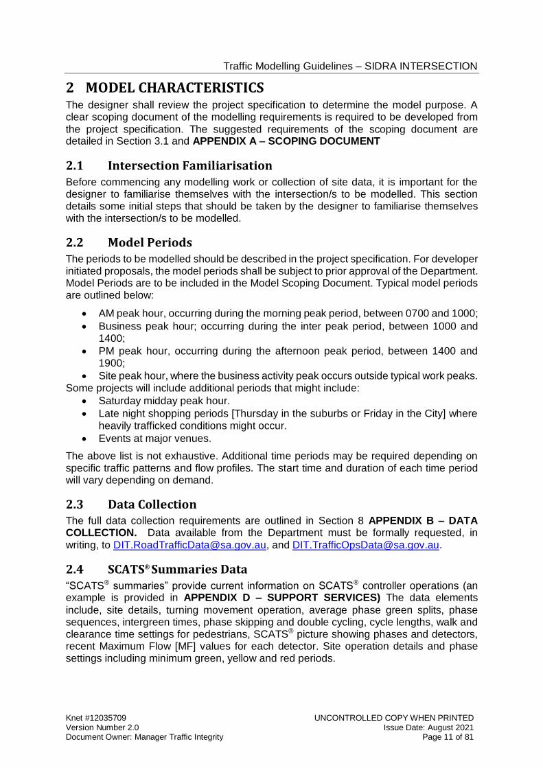
2.2 Model Periods The periods to be modelled should be described in the project specification. For developer initiated proposals, the model periods shall be subject to prior approval of the Department. Model Periods are to be included in the Model Scoping Document. Typical model periods are outlined below:
AM peak hour, occurring during the morning peak period, between 0700 and 1000;
Business peak hour; occurring during the inter peak period, between 1000 and 1400;
PM peak hour, occurring during the afternoon peak period, between 1400 and 1900;
Site peak hour, where the business activity peak occurs outside typical work peaks. Some projects will include additional periods that might include:
Saturday midday peak hour.
Late night shopping periods [Thursday in the suburbs or Friday in the City] where heavily trafficked conditions might occur.
Events at major venues.
The above list is not exhaustive. Additional time periods may be required depending on specific traffic patterns and flow profiles. The start time and duration of each time period will vary depending on demand.
2.3 Data Collection The full data collection requirements are outlined in Section 8 APPENDIX B – DATA COLLECTION. Data available from the Department must be formally requested, in writing, to [email protected], and [email protected].
2.4 SCATS® Summaries Data
“SCATS® summaries” provide current information on SCATS® controller operations (an example is provided in APPENDIX D – SUPPORT SERVICES) The data elements
include, site details, turning movement operation, average phase green splits, phase sequences, intergreen times, phase skipping and double cycling, cycle lengths, walk and clearance time settings for pedestrians, SCATS® picture showing phases and detectors, recent Maximum Flow [MF] values for each detector. Site operation details and phase settings including minimum green, yellow and red periods.
Traffic Modelling Guidelines – SIDRA INTERSECTION
Knet #12035709 UNCONTROLLED COPY WHEN PRINTED Version Number 2.0 Issue Date: August 2021 Document Owner: Manager Traffic Integrity Page 12 of 81
2.5 Non-Green (Yellow / Red) Time The time used by traffic during non-green periods can influence road capacity and adjustment for this behaviour should therefore be a requirement during model calibration. Additional road capacity created by aggressive vehicle behaviour can be reflected in a traffic model but must be reported in the Traffic Signals Operation Performance Report for model auditing purposes. These periods must not be adjusted arbitrarily to achieve degrees of saturation less than 100%.
Non-green periods should be accounted for if vehicles are observed on-site to behave aggressively at the stop line, e.g. by crossing a stop line near the start of red. Site observations should record the total time (in seconds) utilised by traffic during non-green periods for each peak period.
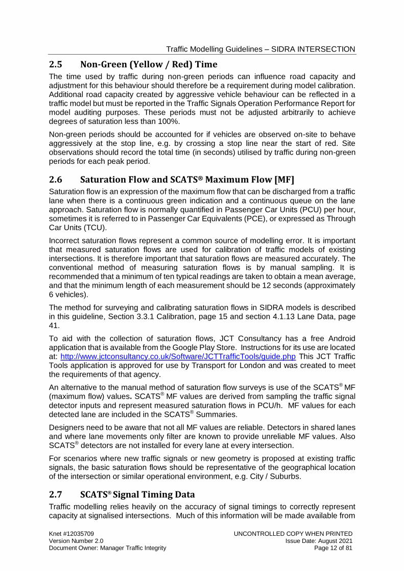
2.6 Saturation Flow and SCATS® Maximum Flow [MF] Saturation flow is an expression of the maximum flow that can be discharged from a traffic lane when there is a continuous green indication and a continuous queue on the lane approach. Saturation flow is normally quantified in Passenger Car Units (PCU) per hour, sometimes it is referred to in Passenger Car Equivalents (PCE), or expressed as Through Car Units (TCU).
Incorrect saturation flows represent a common source of modelling error. It is important that measured saturation flows are used for calibration of traffic models of existing intersections. It is therefore important that saturation flows are measured accurately. The conventional method of measuring saturation flows is by manual sampling. It is recommended that a minimum of ten typical readings are taken to obtain a mean average, and that the minimum length of each measurement should be 12 seconds (approximately 6 vehicles).
The method for surveying and calibrating saturation flows in SIDRA models is described in this guideline, Section 3.3.1 Calibration, page 15 and section 4.1.13 Lane Data, page 41.
To aid with the collection of saturation flows, JCT Consultancy has a free Android application that is available from the Google Play Store. Instructions for its use are located at: http://www.jctconsultancy.co.uk/Software/JCTTrafficTools/guide.php This JCT Traffic Tools application is approved for use by Transport for London and was created to meet the requirements of that agency.
An alternative to the manual method of saturation flow surveys is use of the SCATS® MF (maximum flow) values. SCATS® MF values are derived from sampling the traffic signal detector inputs and represent measured saturation flows in PCU/h. MF values for each detected lane are included in the SCATS® Summaries.
Designers need to be aware that not all MF values are reliable. Detectors in shared lanes and where lane movements only filter are known to provide unreliable MF values. Also SCATS® detectors are not installed for every lane at every intersection.
For scenarios where new traffic signals or new geometry is proposed at existing traffic signals, the basic saturation flows should be representative of the geographical location of the intersection or similar operational environment, e.g. City / Suburbs.
2.7 SCATS® Signal Timing Data Traffic modelling relies heavily on the accuracy of signal timings to correctly represent capacity at signalised intersections. Much of this information will be made available from
Traffic Modelling Guidelines – SIDRA INTERSECTION
Knet #12035709 UNCONTROLLED COPY WHEN PRINTED Version Number 2.0 Issue Date: August 2021 Document Owner: Manager Traffic Integrity Page 13 of 81
[email protected], in the form of SCATS® Summaries. The designer is however responsible for ensuring that this information is configured appropriately in their model.
For calibration of the base case model signal timing data should be compatible with the same model periods as other traffic data including traffic volumes. If the SCATS® Summaries do not match all the model periods required in the design specification additional data can be readily obtained on request.
2.8 Queue Lengths Queue length data can be a useful check for model validation at locations where queues persist from one signal cycle to the next. Surveyed measurements are normally taken at a consistent point in the signal cycle (e.g. at the start of green), specified for each traffic lane and measured in metres.
The level of accuracy in queue measurement surveys can often be lower than for other surveys as the definition of a queue can be ambiguous as well as difficult to identify. At some locations the maximum length of queues has been found to be inconsistent and therefore is be unreliable for validation purposes. Despite this it remains important to identify on which approaches the maximum queue lengths are occurring for each model period.
For a single intersection the queue prediction model in SIDRA does not automatically take account of downstream queues which impact a site. The downstream queue effect can influence the observed queues for use as a validation measure, manual capacity reduction should be applied where it has been observed that lanes are blocked during periods where vehicles should otherwise be moving.
2.9 Traffic Volume Data and Classification Data Vehicle Turning Movement Surveys of traffic volumes at intersections, which includes vehicle classification data, is available on request from [email protected] A typical example of the PDF format report is shown in 8.1 Traffic Count Data.
This intersection Vehicle Turning Movement Survey data is not seasonally corrected and may not be sufficiently recent to represent current circumstances. The designer will therefore need to determine if this data needs to be supplemented by additional traffic surveys.
Lane volume data from detector counts is also available in the form of SCATS® Volume Store (VS) data on request from [email protected]. This data is recorded as a daily record in “vehicle” numbers at 5 minute intervals and is available from a large database which enables data to be extracted for a selected period.
A combination of the manual turning movement data and SCATS® VS data will normally provide a sufficiently rich source of information to enable validation of base case models for existing intersections with traffic signal operational data for each of the model periods.
Austroads standard 13 vehicle type classification data from automatic field devices is also available from [email protected] but this data often has a limited
geographical distribution. Care needs to be taken that the information is temporally and spatially relevant to the intersection site being analysed.
Traffic Modelling Guidelines – SIDRA INTERSECTION
Knet #12035709 UNCONTROLLED COPY WHEN PRINTED Version Number 2.0 Issue Date: August 2021 Document Owner: Manager Traffic Integrity Page 14 of 81
3 MODEL DEVELOPMENT
3.1 Model Scoping Document A model scoping document shall be prepared by the designer on the basis of a client brief or contract specification and be submitted to the Department for approval at the commencement of modelling. The model scoping document will clarify the requirements of the brief in greater detail. It will outline the purpose for the model, such as, for assessment of geometrical arrangements, capacity calculations, delay evaluation, optimisation of phases, phase sequences, green splits and offsets for operational SCATS inputs. The document should report the type of project for which the model is being created, the location of the intersections, the traffic flows being used and their sources, traffic control data sources and the model time periods, and the stages of model development to be considered.
3.2 Stages of Model Development The stages are:
A “base case” which comprises a representation of the existing situation, fully calibrated and validated. The existing situation shall comprise existing geometry, traffic signal control phasing and green times, traffic volumes and saturation flows.
An “interim model”, shall comprise the base case model with optimised traffic signals phasing but with the same cycle length and minimum green time/pedestrian time constraints. This may be required to provide a suitable model to compare with optimised scenario models.
A “base case for comparison” which represents a future year projection of the base case or the “interim model” to represent the start of the project year. This may include future year projected traffic volumes and the influence of recently completed or committed adjacent projects and developments.
A “future year” model shall represent a worst case scenario for comparison for with and without completion of a project. A “future year” model shall use the “base case for comparison” model but include a projection of the traffic volumes to a “future year” when the project is expected to be completed. The future year model will include an increase in traffic through growth projections and include the influence of adjacent projects or developments anticipated to be completed by the future year.
Project “Scenario” models shall represent each of the proposed project or development options including future year traffic projections, proposed geometric changes, proposed traffic control changes including traffic signal phasing optimisation, and including new or modified intersections.
3.3 Base Case Model Every SIDRA project prepared for the Department must have a base case model built to compare with the project options.
The base case for the purposes of these guidelines is a representation of the existing operational condition of the existing intersection without any proposed modifications. (Note: For an economic assessment a “base case” may represent a future year which might also include projected improvements to the intersection and if it is a requirement to model this situation it will be referred to a “base case for comparison” in these guidelines)
Traffic Modelling Guidelines – SIDRA INTERSECTION
Knet #12035709 UNCONTROLLED COPY WHEN PRINTED Version Number 2.0 Issue Date: August 2021 Document Owner: Manager Traffic Integrity Page 15 of 81
The base case model must be fully calibrated and validated for each time period being considered for the project options. Usually the time periods would be AM peak hour, a representative Business hour and the PM peak hour. (Refer to Section 2.2 Model Periods for a full description of period options).
The basic data for a base case model for existing intersections shall be representative of existing traffic signal phasing, geometry, and saturation flows and traffic volumes. The sources of data available from the Department are outlined in Section 2.3 Data Collection. Plans of the existing geometry are also available from the Department, however it is the designer’s responsibility to ensure that all the information provided by the Department is an accurate representation of the current site conditions.
3.3.1 Calibration For SIDRA models calibration shall comprise checks of the input data to ensure that the base case (i.e. the latest valid data representing the existing intersection) data is adequately represented in the model.
The calibration process should be based on various traffic data, including surveys and site observations. This data, for traffic signals shall principally include traffic flow, saturation flow, traffic signal phase sequences, phase green time splits, traffic signal timing settings for yellow, all red and pedestrian phases, and geometric parameters.
The SIDRA INTERSECTION 9 User Guide, has some advice on calibration methods in Sections 2.6 “Model Calibration” and 5.4.3 “Lane Data”.
In the SIDRA INTERSECTION 9 User Guide it recommends that measured saturation flow rates should not be specified as the “Basic Saturation Flow” in the approach lane data parameter, but instead modifying the other lane factors that will influence the SIDRA estimation of the saturation flow before adjusting the “Basic Saturation Flow” such that the output saturation flow is equivalent to the measured saturation flow. This will maintain the lane variability provided by the data input into the Lane Geometry dialogue for any project scenarios.
Measured saturation flow values should therefore not be input directly, lane by lane into the Lane Geometry<Lane data “Basic Saturation Flow” field (section 4.1.13 Lane Data). The saturation flow calibration shall comprise a comparison of measured and adjusted saturation flows post initial processing of the model. It is most important that differences in the saturation flows are identified in the report and the adjustments made also reported. Measured saturation flows for through lanes are assumed to be more reliable than turning lanes.
Only after the appropriate adjustments to reflect the intersection geometry, where the through lane measured saturation flows for all approaches of an intersection are found to be different than the adjusted processed values from SIDRA should the designer consider selecting a more appropriate “Basic Saturation Flow” for all lanes in the intersection.
Before calibrating saturation flows in SIDRA ensure that all the global factors are set to unity, including the Area Type Factors (ATF) (section 4.1.3 Site Input Data) and “saturation flow scaling”. To eliminate saturation flow scaling for calibrating the model ensure that the Demand and Sensitivity is set to “none” (section 4.1.7 Demand and Sensitivity Dialogue).
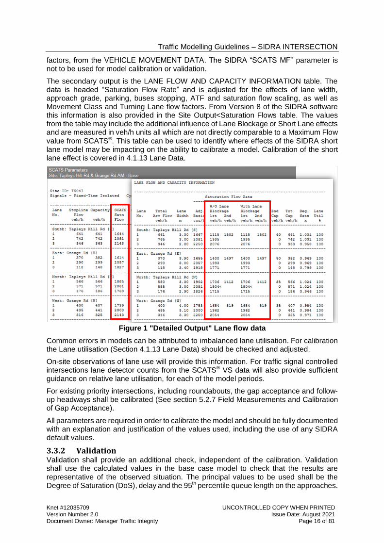
On-site measured saturation flows in units of passenger cars per hour may be compared with values for individual lanes shown in the SIDRA Detailed Output table (illustrated below). The primary reference is in the “SCATS Parameters” table. The “SCATS Satn Flow” output is the “basic saturation flow”, adjusted for lane width, approach grade, ATF, saturation flow scaling, and the influence of vehicles turning, using the turn adjustment
Traffic Modelling Guidelines – SIDRA INTERSECTION
Knet #12035709 UNCONTROLLED COPY WHEN PRINTED Version Number 2.0 Issue Date: August 2021 Document Owner: Manager Traffic Integrity Page 16 of 81
factors, from the VEHICLE MOVEMENT DATA. The SIDRA “SCATS MF” parameter is not to be used for model calibration or validation.
The secondary output is the LANE FLOW AND CAPACITY INFORMATION table. The data is headed “Saturation Flow Rate” and is adjusted for the effects of lane width, approach grade, parking, buses stopping, ATF and saturation flow scaling, as well as Movement Class and Turning Lane flow factors. From Version 8 of the SIDRA software this information is also provided in the Site Output<Saturation Flows table. The values from the table may include the additional influence of Lane Blockage or Short Lane effects and are measured in veh/h units all which are not directly comparable to a Maximum Flow value from SCATS®. This table can be used to identify where effects of the SIDRA short lane model may be impacting on the ability to calibrate a model. Calibration of the short lane effect is covered in 4.1.13 Lane Data.
Figure 1 "Detailed Output" Lane flow data
Common errors in models can be attributed to imbalanced lane utilisation. For calibration the Lane utilisation (Section 4.1.13 Lane Data) should be checked and adjusted.
On-site observations of lane use will provide this information. For traffic signal controlled intersections lane detector counts from the SCATS® VS data will also provide sufficient guidance on relative lane utilisation, for each of the model periods.
For existing priority intersections, including roundabouts, the gap acceptance and follow-up headways shall be calibrated (See section 5.2.7 Field Measurements and Calibration of Gap Acceptance).
All parameters are required in order to calibrate the model and should be fully documented with an explanation and justification of the values used, including the use of any SIDRA default values.
3.3.2 Validation Validation shall provide an additional check, independent of the calibration. Validation shall use the calculated values in the base case model to check that the results are representative of the observed situation. The principal values to be used shall be the Degree of Saturation (DoS), delay and the 95th percentile queue length on the approaches.
Traffic Modelling Guidelines – SIDRA INTERSECTION
Knet #12035709 UNCONTROLLED COPY WHEN PRINTED Version Number 2.0 Issue Date: August 2021 Document Owner: Manager Traffic Integrity Page 17 of 81
Where approaches are known to be over-saturated in peak periods and the models reflect this by calculated values above 0.9 DoS, it should not be necessary to undertake site surveys to establish the measured DoS values. At unsaturated sites, on-site measurements of degrees of saturation may be necessary in order to validate the model.
The same JCT Traffic Tools application (see page 12) will also calculate DoS values from on-site measurements having established a valid saturation flow from measured data.
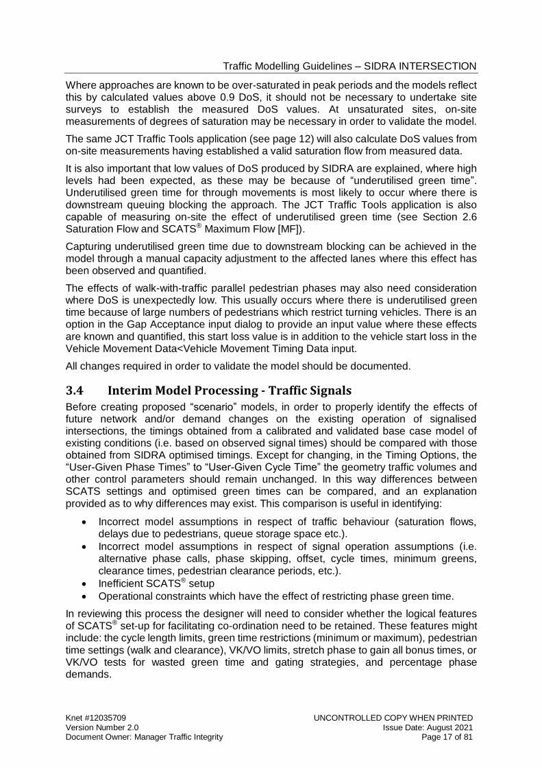
It is also important that low values of DoS produced by SIDRA are explained, where high levels had been expected, as these may be because of “underutilised green time”. Underutilised green time for through movements is most likely to occur where there is downstream queuing blocking the approach. The JCT Traffic Tools application is also capable of measuring on-site the effect of underutilised green time (see Section 2.6 Saturation Flow and SCATS® Maximum Flow [MF]).
Capturing underutilised green time due to downstream blocking can be achieved in the model through a manual capacity adjustment to the affected lanes where this effect has been observed and quantified.
The effects of walk-with-traffic parallel pedestrian phases may also need consideration where DoS is unexpectedly low. This usually occurs where there is underutilised green time because of large numbers of pedestrians which restrict turning vehicles. There is an option in the Gap Acceptance input dialog to provide an input value where these effects are known and quantified, this start loss value is in addition to the vehicle start loss in the Vehicle Movement Data<Vehicle Movement Timing Data input.
All changes required in order to validate the model should be documented.
3.4 Interim Model Processing - Traffic Signals Before creating proposed “scenario” models, in order to properly identify the effects of future network and/or demand changes on the existing operation of signalised intersections, the timings obtained from a calibrated and validated base case model of existing conditions (i.e. based on observed signal times) should be compared with those obtained from SIDRA optimised timings. Except for changing, in the Timing Options, the “User-Given Phase Times” to “User-Given Cycle Time” the geometry traffic volumes and other control parameters should remain unchanged. In this way differences between SCATS settings and optimised green times can be compared, and an explanation provided as to why differences may exist. This comparison is useful in identifying:
Incorrect model assumptions in respect of traffic behaviour (saturation flows, delays due to pedestrians, queue storage space etc.).
Incorrect model assumptions in respect of signal operation assumptions (i.e. alternative phase calls, phase skipping, offset, cycle times, minimum greens, clearance times, pedestrian clearance periods, etc.).
Inefficient SCATS® setup
Operational constraints which have the effect of restricting phase green time.
In reviewing this process the designer will need to consider whether the logical features of SCATS® set-up for facilitating co-ordination need to be retained. These features might include: the cycle length limits, green time restrictions (minimum or maximum), pedestrian time settings (walk and clearance), VK/VO limits, stretch phase to gain all bonus times, or VK/VO tests for wasted green time and gating strategies, and percentage phase demands.
Traffic Modelling Guidelines – SIDRA INTERSECTION
Knet #12035709 UNCONTROLLED COPY WHEN PRINTED Version Number 2.0 Issue Date: August 2021 Document Owner: Manager Traffic Integrity Page 18 of 81
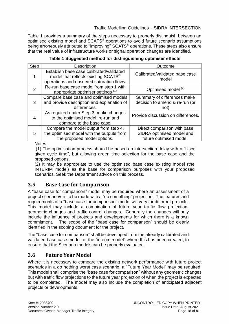
Table 1 provides a summary of the steps necessary to properly distinguish between an optimised existing model and SCATS® operations to avoid future scenario assumptions being erroneously attributed to “improving” SCATS® operations. These steps also ensure that the real value of infrastructure works or signal operation changes are identified.
Table 1 Suggested method for distinguishing optimiser effects
Step Description Outcome
1 Establish base case calibrated/validated
model that reflects existing SCATS® operations and observed saturation flows.
Calibrated/validated base case model
2 Re-run base case model from step 1 with
appropriate optimiser settings (1) Optimised model (2)
3 Compare base case and optimised models and provide description and explanation of
differences.
Summary of differences make decision to amend & re-run (or
not)
4 As required under Step 3, make changes
to the optimised model, re-run and compare to the base case.
Provide discussion on differences.
5 Compare the model output from step 4,
the optimised model with the outputs from the proposed model options.
Direct comparison with base SIDRA optimised model and
future optimised model.
Notes: (1) The optimisation process should be based on intersection delay with a “User given cycle time”, but allowing green time selection for the base case and the proposed options. (2) It may be appropriate to use the optimised base case existing model (the INTERIM model) as the base for comparison purposes with your proposed scenarios. Seek the Department advice on this process.
3.5 Base Case for Comparison A “base case for comparison” model may be required where an assessment of a project scenario/s is to be made with a “do something” projection. The features and requirements of a “base case for comparison” model will vary for different projects. This model may include a combination of future year traffic flow projection, geometric changes and traffic control changes. Generally the changes will only include the influence of projects and developments for which there is a known commitment. The scope of the “base case for comparison” should be clearly identified in the scoping document for the project.
The “base case for comparison” shall be developed from the already calibrated and validated base case model, or the “interim model” where this has been created, to ensure that the Scenario models can be properly evaluated.
3.6 Future Year Model Where it is necessary to compare the existing network performance with future project scenarios in a do nothing worst case scenario, a “Future Year Model” may be required. This model shall comprise the “base case for comparison” without any geometric changes but with traffic flow projections to the future year projection of when the project is expected to be completed. The model may also include the completion of anticipated adjacent projects or developments.
Traffic Modelling Guidelines – SIDRA INTERSECTION
Knet #12035709 UNCONTROLLED COPY WHEN PRINTED Version Number 2.0 Issue Date: August 2021 Document Owner: Manager Traffic Integrity Page 19 of 81
The designer shall consider that for some future year models this might provide unrealistic results, especially if the traffic demand far exceeds the available intersection capacity.
3.7 Projected Scenarios The base case, calibrated and validated model shall be used as the skeleton model for the creation of projected scenarios; and the tested parameters should not be changed. Only the minimum changes necessary to reflect the new configuration should be made. (See Sections 3.4 and 3.5 regarding the “interim model” and “base case for comparison”)
Before commencing modelling the designer shall discuss with the Department, how it is proposed to incorporate the effects of future year projected traffic growth with trips generated by proposed developments into the SIDRA models. (See section 3.1 Model Scoping Document). The approval of projected traffic flows is required by the Department prior to model commencement.
As part of the traffic analysis representing future year projections the designer is required to provide a “day of opening” traffic impact assessment, to demonstrate that on completion of the development it will have no detrimental effect on current road and traffic operations
3.7.1 Development Applications and Traffic Generation For new trip generating developments adjacent to an existing road managed by the Department the designer shall demonstrate the likely trip generation and route choice, to and from the development, and how this will affect adjacent intersections, as well as direct accesses to the development.
Where recent trip generation rates are available from South Australian site surveys, this trip data should be used for the model analysis. The source of the data is to be included in reports.
Where South Australian data is not readily available it is acceptable to use the trip
generation rates from the TfNSW RMS Guide to Traffic Generating Developments and updated surveys (see references).1 2
Where the traffic generation rates are not provided or available from other sources, appropriate rates should be determined by undertaking surveys of similar land use types within South Australia. The survey data should be included in the design report.
Trip generation rates should be applied to the various land use types and components of the development to determine the overall traffic generation rates. It is not appropriate to use gross trip rates where these are likely to predict lower traffic generation rates.
Given the likely variation of trip rates from similar types of developments over time and location it is essential that trip rates are approved by the Department before model development commences.
Predicted trip rates from the development and future year traffic growth projections are applied to the model for the assessment of the developments overall traffic impact.
1 Roads and Traffic Authority NSW (2002), Guide to Traffic Generating Developments version 2.2
October 2002. 2 Transport for New South Wales, Roads and Maritime Services - Technical Direction TDT 2013/04a - Guide to Traffic Generating Developments - Updated traffic surveys – August 2013.
Traffic Modelling Guidelines – SIDRA INTERSECTION
Knet #12035709 UNCONTROLLED COPY WHEN PRINTED Version Number 2.0 Issue Date: August 2021 Document Owner: Manager Traffic Integrity Page 20 of 81
3.7.2 Future Year Traffic Projections For all projects or development proposals affecting the Department road network, future year traffic projections are to be made, based on a combination of attributes including changes in the physical transportation network, land use and social changes that reflect an overall change in traffic volumes.
For new project scenarios, the designer shall assess the performance of the future year traffic predictions in the proposed scenarios to provide confirmation that the scenario achieves the project functional and operational requirements in accordance with the contract scope.
Before modelling commences projected traffic volumes of a proposed development shall be agreed by the designer with representative sections of the Department. Currently including both the Transport Planning and Program Development Division, Transport Analytics Directorate, and the Road and Marine Services Division, Traffic Integrity Section.
3.7.3 DPTI Standard Traffic Signal Conventions. The standard conventions for labelling traffic signals are shown in the Department Standard Drawing 6841 Sheets 1 and 2, “Traffic Signals Design Guide Detectors Signal Groups Phasing and Pole Numbering Standards”. These drawings can be found at the traffic signals section of the master specification web page (see the hyperlink on page 8).
These drawings also show the naming conventions for signal Groups and detectors.
Wherever practical these naming conventions shall be used in models.
The drawings also show the Department standard phasing arrangements in the following forms:
Single phase.
Two phase.
Three phase T-junction.
Four phase T-junction.
Split Approach.
Leading Turn.
Trailing Turn.
Leading Trailing Turns.
Single Diamond Overlap.
Double Diamond Overlap.
Pedestrian Activated Crossing.
These phase arrangements and labelling conventions should be used in all types of proposed intersection modelling.
3.7.4 Design of Minimum Phase Times and Intergreen Periods Modifications to intersection design or method of control may typically require recalculation of the phase minimum and phase intergreen periods. To determine appropriate values of yellow and red time refer to the Department Traffic Signal Standard: Signal Timings (available from the Department standards web site “technical standards and guidelines” https://dit.sa.gov.au/documents), which details phase minimum and
intergreen times and pedestrian phase times i.e. walk and clearance.
For all new intersections use the Traffic Signal Standard: Signal Timings to design intergreen periods.
Traffic Modelling Guidelines – SIDRA INTERSECTION
Knet #12035709 UNCONTROLLED COPY WHEN PRINTED Version Number 2.0 Issue Date: August 2021 Document Owner: Manager Traffic Integrity Page 21 of 81
A copy of the Yellow/Red output should be included in the Traffic Signal Operational Performance Report (See Section 3.9 Model Reporting Requirements).
3.8 Measures of Performance SIDRA offers a variety of output features that can help in the analysis and reporting of model performance, which are detailed in this section. The core performance elements that should be assessed for any intersection modelling using SIDRA are:
Degree of Saturation (DoS).
95th percentile Back of Queue distance (veh or m).
Level of Service (LoS).
Vehicle delays (veh/h) or (pcu/h).
Number of vehicle stops.
The performance assessment of the first 3 items needs to be considered on a lane by lane basis.
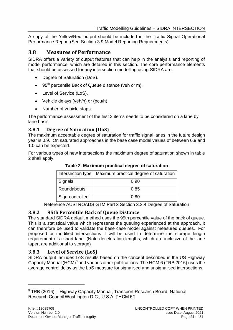
3.8.1 Degree of Saturation (DoS) The maximum acceptable degree of saturation for traffic signal lanes in the future design year is 0.9. On saturated approaches in the base case model values of between 0.9 and 1.0 can be expected.
For various types of new intersections the maximum degree of saturation shown in table 2 shall apply.
Table 2 Maximum practical degree of saturation
Intersection type Maximum practical degree of saturation
Signals 0.90
Roundabouts 0.85
Sign-controlled 0.80
Reference AUSTROADS GTM Part 3 Section 3.2.4 Degree of Saturation
3.8.2 95th Percentile Back of Queue Distance The standard SIDRA default method uses the 95th percentile value of the back of queue. This is a statistical value which represents the queuing experienced at the approach. It can therefore be used to validate the base case model against measured queues. For proposed or modified intersections it will be used to determine the storage length requirement of a short lane. (Note deceleration lengths, which are inclusive of the lane taper, are additional to storage)
3.8.3 Level of Service (LoS) SIDRA output includes LoS results based on the concept described in the US Highway Capacity Manual (HCM)3 and various other publications. The HCM 6 (TRB 2016) uses the average control delay as the LoS measure for signalised and unsignalised intersections.
3 TRB (2016), - Highway Capacity Manual, Transport Research Board, National Research Council Washington D.C., U.S.A. [“HCM 6”]
Traffic Modelling Guidelines – SIDRA INTERSECTION
Knet #12035709 UNCONTROLLED COPY WHEN PRINTED Version Number 2.0 Issue Date: August 2021 Document Owner: Manager Traffic Integrity Page 22 of 81
The HCM (2016) LoS increments is the standard applied to models by the Department, in accordance with the parameter setting “Delay (SIDRA)” (see Section 4.1.6 Parameter setting dialogue)
Level of service is primarily used as a limit control for proposed scenarios to ensure that the scenario represents a practical proposal. As a performance measure the minimum requirement is LoS D for intersections in project scenarios for the future design year.
Level of service can however also be used to demonstrate a coarse comparison between the base case and the scenarios. It is not useful for verifying base case models.
3.8.4 Delays and Stops The main measure of comparative performance output from SIDRA models is the overall vehicle delay or travel time (vehicles hours per hour) and the number of vehicle stops (vehicles per hour). These measures are only comparative if intersections are treated equally as isolated controls.
3.9 Model Reporting Requirements Detailed advice on reporting requirements is also to be found in Section 6 Model Reports, of these guidelines.
Where there is an exception to these guidelines the exception and the justification for the change shall be included in the model report, any design reports and the TSOPR (see below)
In addition to any other modelling reporting requirements, where there is a resulting modification to existing signals or a new signal installation is to be provided the traffic signals design is required to conform to the Traffic Signals Design Master Specification (RD-EL-D2) which requires a Traffic Signal Operations Performance Report (TSOPR) to be provided (a link to the specification is provided on page 8).
Traffic Modelling Guidelines – SIDRA INTERSECTION
Knet #12035709 UNCONTROLLED COPY WHEN PRINTED Version Number 2.0 Issue Date: August 2021 Document Owner: Manager Traffic Integrity Page 23 of 81
4 MODEL CONSTRUCTION - TRAFFIC SIGNALS
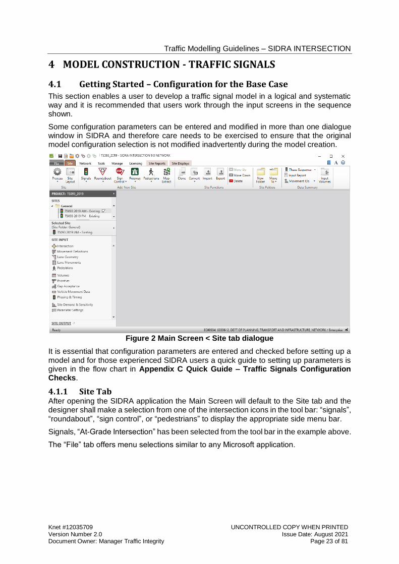
4.1 Getting Started – Configuration for the Base Case This section enables a user to develop a traffic signal model in a logical and systematic way and it is recommended that users work through the input screens in the sequence shown.
Some configuration parameters can be entered and modified in more than one dialogue window in SIDRA and therefore care needs to be exercised to ensure that the original model configuration selection is not modified inadvertently during the model creation.
Figure 2 Main Screen < Site tab dialogue
It is essential that configuration parameters are entered and checked before setting up a model and for those experienced SIDRA users a quick guide to setting up parameters is given in the flow chart in Appendix C Quick Guide – Traffic Signals Configuration Checks.
4.1.1 Site Tab After opening the SIDRA application the Main Screen will default to the Site tab and the designer shall make a selection from one of the intersection icons in the tool bar: “signals”, “roundabout”, “sign control”, or “pedestrians” to display the appropriate side menu bar.
Signals, “At-Grade Intersection” has been selected from the tool bar in the example above.
The “File” tab offers menu selections similar to any Microsoft application.
Traffic Modelling Guidelines – SIDRA INTERSECTION
Knet #12035709 UNCONTROLLED COPY WHEN PRINTED Version Number 2.0 Issue Date: August 2021 Document Owner: Manager Traffic Integrity Page 24 of 81
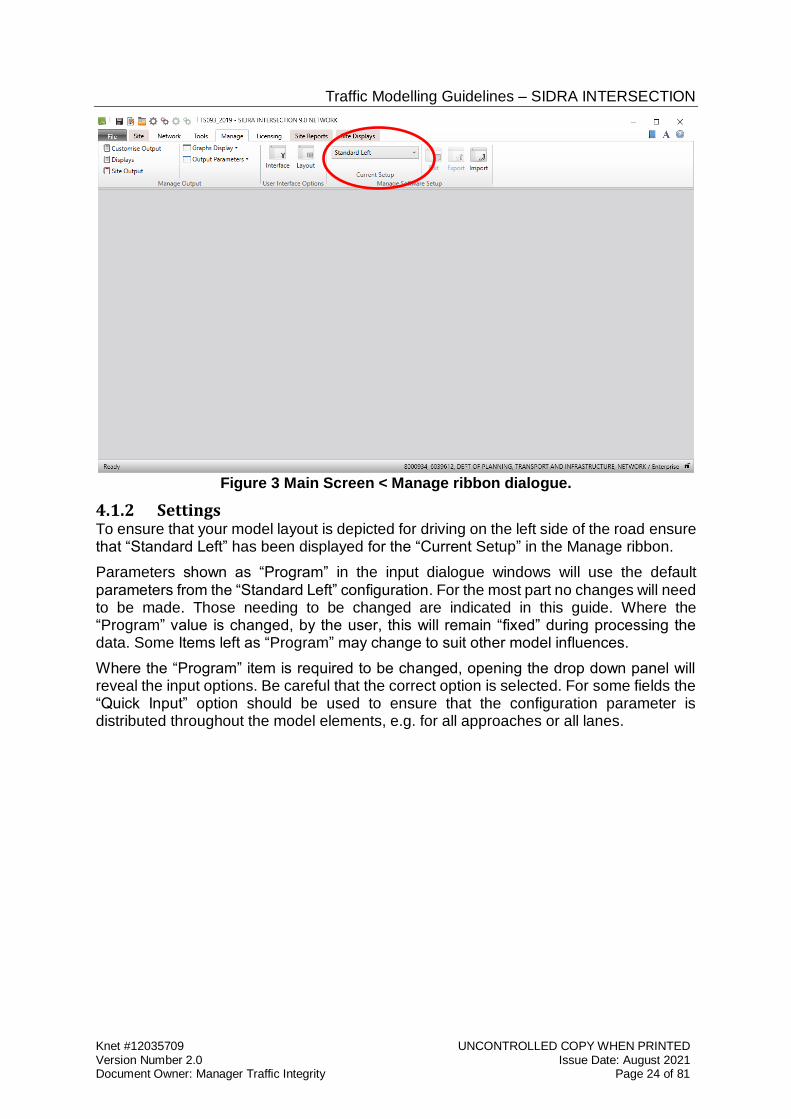
Figure 3 Main Screen < Manage ribbon dialogue.
4.1.2 Settings To ensure that your model layout is depicted for driving on the left side of the road ensure that “Standard Left” has been displayed for the “Current Setup” in the Manage ribbon.
Parameters shown as “Program” in the input dialogue windows will use the default parameters from the “Standard Left” configuration. For the most part no changes will need to be made. Those needing to be changed are indicated in this guide. Where the “Program” value is changed, by the user, this will remain “fixed” during processing the data. Some Items left as “Program” may change to suit other model influences.
Where the “Program” item is required to be changed, opening the drop down panel will reveal the input options. Be careful that the correct option is selected. For some fields the “Quick Input” option should be used to ensure that the configuration parameter is distributed throughout the model elements, e.g. for all approaches or all lanes.
Traffic Modelling Guidelines – SIDRA INTERSECTION
Knet #12035709 UNCONTROLLED COPY WHEN PRINTED Version Number 2.0 Issue Date: August 2021 Document Owner: Manager Traffic Integrity Page 25 of 81
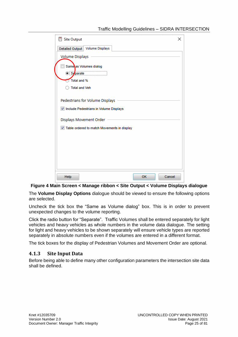
Figure 4 Main Screen < Manage ribbon < Site Output < Volume Displays dialogue
The Volume Display Options dialogue should be viewed to ensure the following options are selected.
Uncheck the tick box the “Same as Volume dialog” box. This is in order to prevent unexpected changes to the volume reporting.
Click the radio button for “Separate”. Traffic Volumes shall be entered separately for light vehicles and heavy vehicles as whole numbers in the volume data dialogue. The setting for light and heavy vehicles to be shown separately will ensure vehicle types are reported separately in absolute numbers even if the volumes are entered in a different format.
The tick boxes for the display of Pedestrian Volumes and Movement Order are optional.
4.1.3 Site Input Data
Before being able to define many other configuration parameters the intersection site data shall be defined.
Traffic Modelling Guidelines – SIDRA INTERSECTION
Knet #12035709 UNCONTROLLED COPY WHEN PRINTED Version Number 2.0 Issue Date: August 2021 Document Owner: Manager Traffic Integrity Page 26 of 81
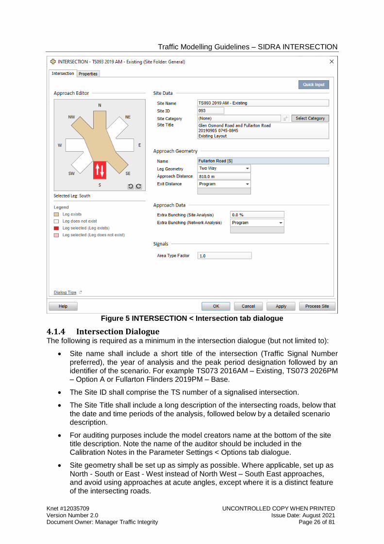
Figure 5 INTERSECTION < Intersection tab dialogue
4.1.4 Intersection Dialogue The following is required as a minimum in the intersection dialogue (but not limited to):
Site name shall include a short title of the intersection (Traffic Signal Number preferred), the year of analysis and the peak period designation followed by an identifier of the scenario. For example TS073 2016AM – Existing, TS073 2026PM – Option A or Fullarton Flinders 2019PM – Base.
The Site ID shall comprise the TS number of a signalised intersection.
The Site Title shall include a long description of the intersecting roads, below that the date and time periods of the analysis, followed below by a detailed scenario description.
For auditing purposes include the model creators name at the bottom of the site title description. Note the name of the auditor should be included in the Calibration Notes in the Parameter Settings < Options tab dialogue.
Site geometry shall be set up as simply as possible. Where applicable, set up as North - South or East - West instead of North West – South East approaches, and avoid using approaches at acute angles, except where it is a distinct feature of the intersecting roads.
Traffic Modelling Guidelines – SIDRA INTERSECTION
Knet #12035709 UNCONTROLLED COPY WHEN PRINTED Version Number 2.0 Issue Date: August 2021 Document Owner: Manager Traffic Integrity Page 27 of 81
Use existing road names to label the approaches and where road names are not unique, include a suffix to show the compass orientation of the approach. If diagonal bearing roads are set up simply as North – South or East – West the suffix should represent the original orientation of the roads.
For all signal sites, the approach distance shall be measured to the next upstream intersection to aid in queue length reporting. Where intersections are closely spaced the “Approach Distance” parameter shall be equal to the measured storage space between intersections, even if longer than the default value, in order to identify upstream blocking effects.
Extra bunching should be applied where applicable to the analysis, refer Section 4.
The Area Type Factor (ATF) shall remain as 1.0.
4.1.5 Project File Naming Conventions It is essential that the project file is saved after entering the first model description in the intersection dialogue.
The file shall include a date code, TS number project name and a version number, in the form yyyymmddTSxxxprojectnameVx e.g. 20160526TS1234unley supermarketV2.
SIDRA does not include a mechanism to lock individual “sites” within the project file, after completion of the data entry project scenarios, including the base case may be inadvertently changed or reprocessed.
Tip: Save a copy the base case models and interim models in separate files to ensure that they are not inadvertently modified when creating the scenario models.
4.1.6 Parameter setting dialogue The Parameter Settings input dialogue can be used to select various model options and specify some model parameters.
Some of the settings in the Parameter Settings input dialogue are common for all intersection types and some are unique. For instance the Roundabout parameters will be shown only if the site type is a roundabout.
Traffic Modelling Guidelines – SIDRA INTERSECTION
Knet #12035709 UNCONTROLLED COPY WHEN PRINTED Version Number 2.0 Issue Date: August 2021 Document Owner: Manager Traffic Integrity Page 28 of 81
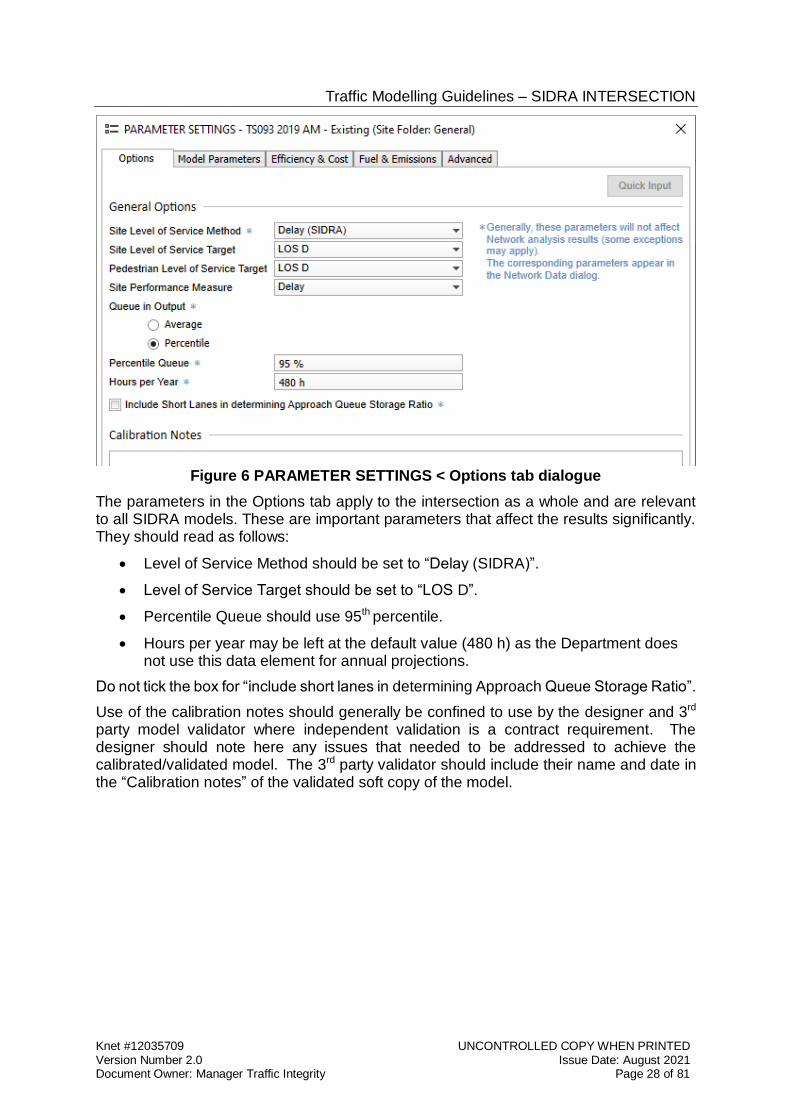
Figure 6 PARAMETER SETTINGS < Options tab dialogue
The parameters in the Options tab apply to the intersection as a whole and are relevant to all SIDRA models. These are important parameters that affect the results significantly. They should read as follows:
Level of Service Method should be set to “Delay (SIDRA)”.
Level of Service Target should be set to “LOS D”.
Percentile Queue should use 95th percentile.
Hours per year may be left at the default value (480 h) as the Department does not use this data element for annual projections.
Do not tick the box for “include short lanes in determining Approach Queue Storage Ratio”.
Use of the calibration notes should generally be confined to use by the designer and 3rd party model validator where independent validation is a contract requirement. The designer should note here any issues that needed to be addressed to achieve the calibrated/validated model. The 3rd party validator should include their name and date in the “Calibration notes” of the validated soft copy of the model.
Traffic Modelling Guidelines – SIDRA INTERSECTION
Knet #12035709 UNCONTROLLED COPY WHEN PRINTED Version Number 2.0 Issue Date: August 2021 Document Owner: Manager Traffic Integrity Page 29 of 81
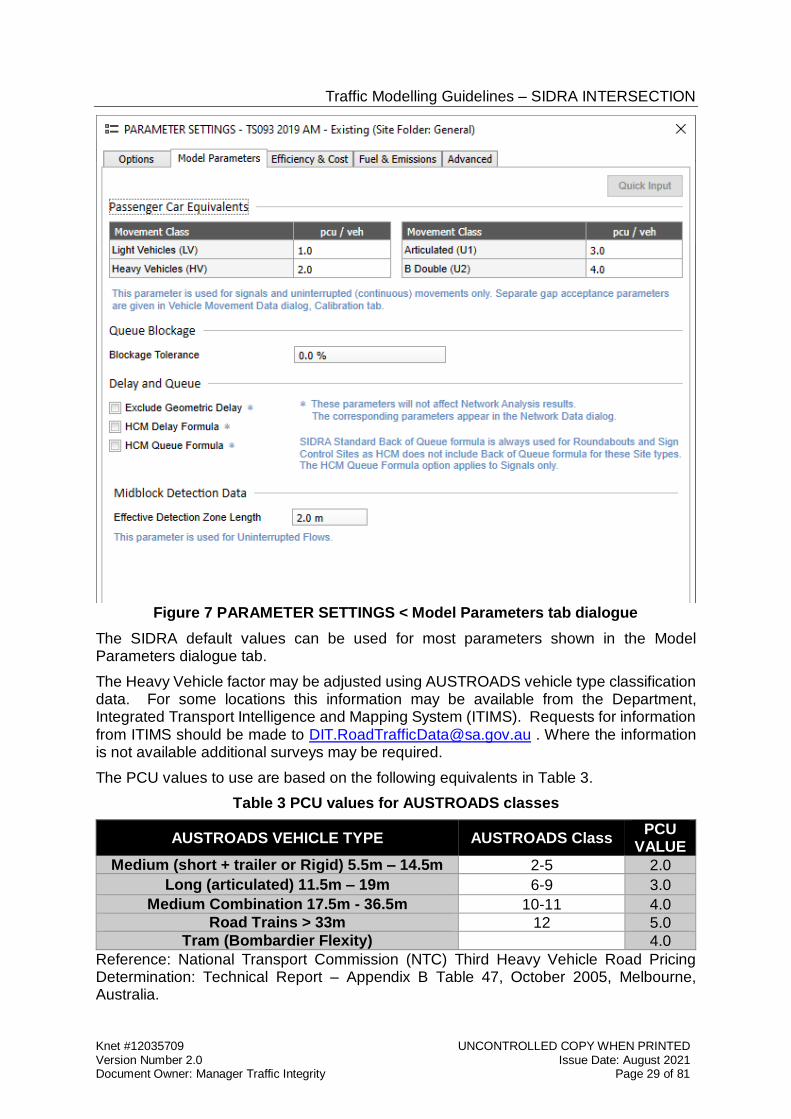
Figure 7 PARAMETER SETTINGS < Model Parameters tab dialogue
The SIDRA default values can be used for most parameters shown in the Model Parameters dialogue tab.
The Heavy Vehicle factor may be adjusted using AUSTROADS vehicle type classification data. For some locations this information may be available from the Department, Integrated Transport Intelligence and Mapping System (ITIMS). Requests for information from ITIMS should be made to [email protected] . Where the information is not available additional surveys may be required.
The PCU values to use are based on the following equivalents in Table 3.
Table 3 PCU values for AUSTROADS classes
AUSTROADS VEHICLE TYPE AUSTROADS Class PCU
VALUE
Medium (short + trailer or Rigid) 5.5m – 14.5m 2-5 2.0
Long (articulated) 11.5m – 19m 6-9 3.0
Medium Combination 17.5m - 36.5m 10-11 4.0 Road Trains > 33m 12 5.0
Tram (Bombardier Flexity) 4.0
Reference: National Transport Commission (NTC) Third Heavy Vehicle Road Pricing Determination: Technical Report – Appendix B Table 47, October 2005, Melbourne, Australia.
Traffic Modelling Guidelines – SIDRA INTERSECTION
Knet #12035709 UNCONTROLLED COPY WHEN PRINTED Version Number 2.0 Issue Date: August 2021 Document Owner: Manager Traffic Integrity Page 30 of 81
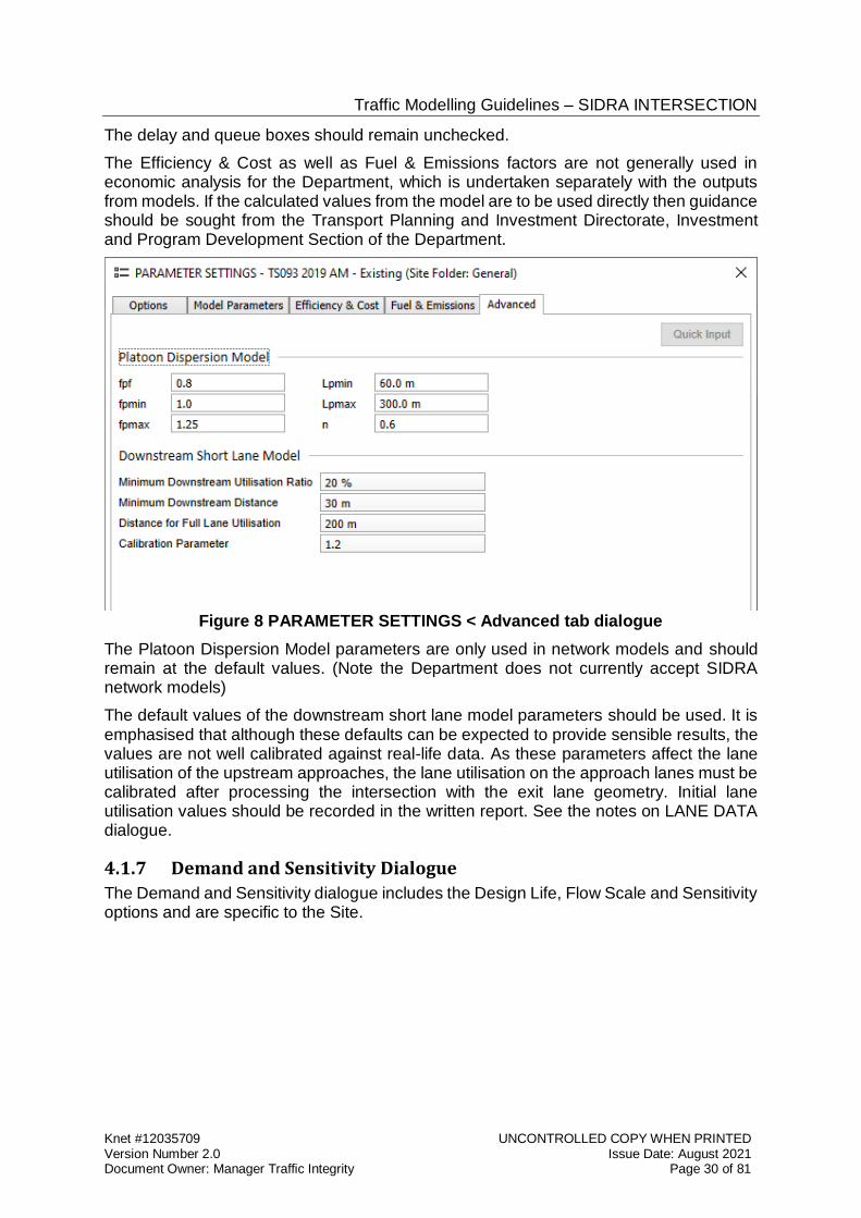
The delay and queue boxes should remain unchecked.
The Efficiency & Cost as well as Fuel & Emissions factors are not generally used in economic analysis for the Department, which is undertaken separately with the outputs from models. If the calculated values from the model are to be used directly then guidance should be sought from the Transport Planning and Investment Directorate, Investment and Program Development Section of the Department.
Figure 8 PARAMETER SETTINGS < Advanced tab dialogue
The Platoon Dispersion Model parameters are only used in network models and should remain at the default values. (Note the Department does not currently accept SIDRA network models)
The default values of the downstream short lane model parameters should be used. It is emphasised that although these defaults can be expected to provide sensible results, the values are not well calibrated against real-life data. As these parameters affect the lane utilisation of the upstream approaches, the lane utilisation on the approach lanes must be calibrated after processing the intersection with the exit lane geometry. Initial lane utilisation values should be recorded in the written report. See the notes on LANE DATA dialogue.
4.1.7 Demand and Sensitivity Dialogue
The Demand and Sensitivity dialogue includes the Design Life, Flow Scale and Sensitivity options and are specific to the Site.
Traffic Modelling Guidelines – SIDRA INTERSECTION
Knet #12035709 UNCONTROLLED COPY WHEN PRINTED Version Number 2.0 Issue Date: August 2021 Document Owner: Manager Traffic Integrity Page 31 of 81
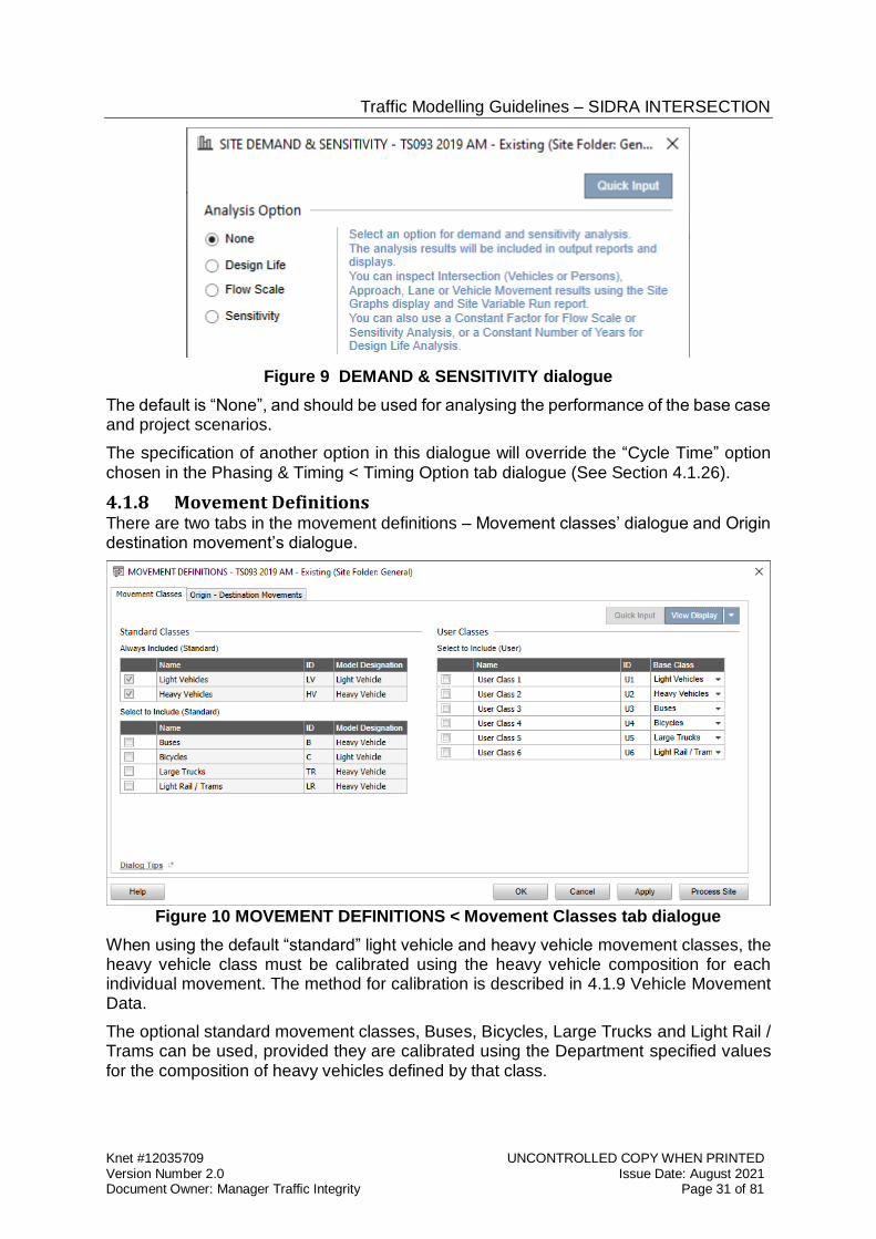
Figure 9 DEMAND & SENSITIVITY dialogue
The default is “None”, and should be used for analysing the performance of the base case and project scenarios.
The specification of another option in this dialogue will override the “Cycle Time” option chosen in the Phasing & Timing < Timing Option tab dialogue (See Section 4.1.26).
4.1.8 Movement Definitions There are two tabs in the movement definitions – Movement classes’ dialogue and Origin destination movement’s dialogue.
Figure 10 MOVEMENT DEFINITIONS < Movement Classes tab dialogue
When using the default “standard” light vehicle and heavy vehicle movement classes, the heavy vehicle class must be calibrated using the heavy vehicle composition for each individual movement. The method for calibration is described in 4.1.9 Vehicle Movement Data.
The optional standard movement classes, Buses, Bicycles, Large Trucks and Light Rail / Trams can be used, provided they are calibrated using the Department specified values for the composition of heavy vehicles defined by that class.
Traffic Modelling Guidelines – SIDRA INTERSECTION
Knet #12035709 UNCONTROLLED COPY WHEN PRINTED Version Number 2.0 Issue Date: August 2021 Document Owner: Manager Traffic Integrity Page 32 of 81
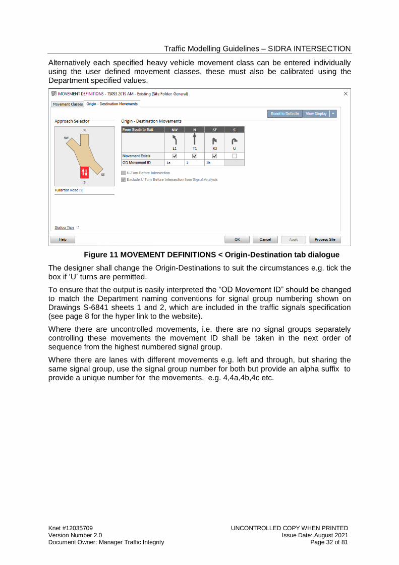
Alternatively each specified heavy vehicle movement class can be entered individually using the user defined movement classes, these must also be calibrated using the Department specified values.
Figure 11 MOVEMENT DEFINITIONS < Origin-Destination tab dialogue
The designer shall change the Origin-Destinations to suit the circumstances e.g. tick the box if ‘U’ turns are permitted.
To ensure that the output is easily interpreted the “OD Movement ID” should be changed to match the Department naming conventions for signal group numbering shown on Drawings S-6841 sheets 1 and 2, which are included in the traffic signals specification (see page 8 for the hyper link to the website).
Where there are uncontrolled movements, i.e. there are no signal groups separately controlling these movements the movement ID shall be taken in the next order of sequence from the highest numbered signal group.
Where there are lanes with different movements e.g. left and through, but sharing the same signal group, use the signal group number for both but provide an alpha suffix to provide a unique number for the movements, e.g. 4,4a,4b,4c etc.
Traffic Modelling Guidelines – SIDRA INTERSECTION
Knet #12035709 UNCONTROLLED COPY WHEN PRINTED Version Number 2.0 Issue Date: August 2021 Document Owner: Manager Traffic Integrity Page 33 of 81
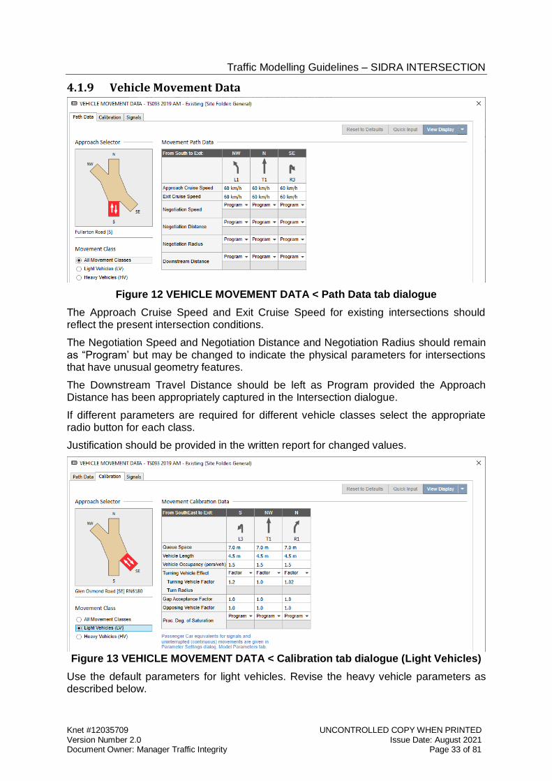
4.1.9 Vehicle Movement Data
Figure 12 VEHICLE MOVEMENT DATA < Path Data tab dialogue
The Approach Cruise Speed and Exit Cruise Speed for existing intersections should reflect the present intersection conditions.
The Negotiation Speed and Negotiation Distance and Negotiation Radius should remain as “Program’ but may be changed to indicate the physical parameters for intersections that have unusual geometry features.
The Downstream Travel Distance should be left as Program provided the Approach Distance has been appropriately captured in the Intersection dialogue.
If different parameters are required for different vehicle classes select the appropriate radio button for each class.
Justification should be provided in the written report for changed values.
Figure 13 VEHICLE MOVEMENT DATA < Calibration tab dialogue (Light Vehicles)
Use the default parameters for light vehicles. Revise the heavy vehicle parameters as described below.
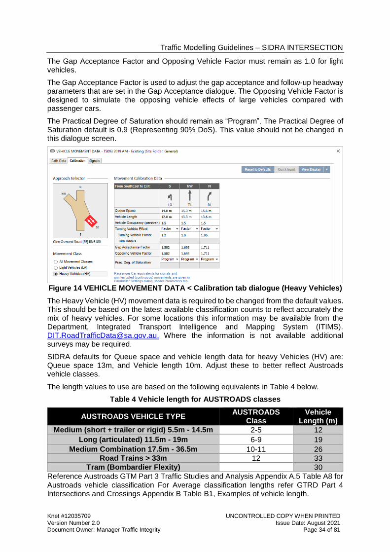
Traffic Modelling Guidelines – SIDRA INTERSECTION
Knet #12035709 UNCONTROLLED COPY WHEN PRINTED Version Number 2.0 Issue Date: August 2021 Document Owner: Manager Traffic Integrity Page 34 of 81
The Gap Acceptance Factor and Opposing Vehicle Factor must remain as 1.0 for light vehicles.
The Gap Acceptance Factor is used to adjust the gap acceptance and follow-up headway parameters that are set in the Gap Acceptance dialogue. The Opposing Vehicle Factor is designed to simulate the opposing vehicle effects of large vehicles compared with passenger cars.
The Practical Degree of Saturation should remain as “Program”. The Practical Degree of Saturation default is 0.9 (Representing 90% DoS). This value should not be changed in this dialogue screen.
Figure 14 VEHICLE MOVEMENT DATA < Calibration tab dialogue (Heavy Vehicles)
The Heavy Vehicle (HV) movement data is required to be changed from the default values. This should be based on the latest available classification counts to reflect accurately the mix of heavy vehicles. For some locations this information may be available from the Department, Integrated Transport Intelligence and Mapping System (ITIMS). [email protected]. Where the information is not available additional surveys may be required.
SIDRA defaults for Queue space and vehicle length data for heavy Vehicles (HV) are: Queue space 13m, and Vehicle length 10m. Adjust these to better reflect Austroads vehicle classes.
The length values to use are based on the following equivalents in Table 4 below.
Table 4 Vehicle length for AUSTROADS classes
AUSTROADS VEHICLE TYPE AUSTROADS
Class Vehicle
Length (m)
Medium (short + trailer or rigid) 5.5m - 14.5m 2-5 12
Long (articulated) 11.5m - 19m 6-9 19
Medium Combination 17.5m - 36.5m 10-11 26 Road Trains > 33m 12 33
Tram (Bombardier Flexity) 30
Reference Austroads GTM Part 3 Traffic Studies and Analysis Appendix A.5 Table A8 for Austroads vehicle classification For Average classification lengths refer GTRD Part 4 Intersections and Crossings Appendix B Table B1, Examples of vehicle length.
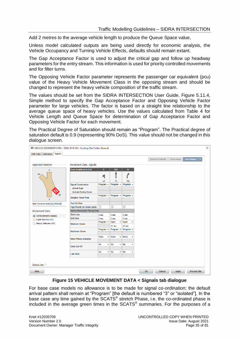
Traffic Modelling Guidelines – SIDRA INTERSECTION
Knet #12035709 UNCONTROLLED COPY WHEN PRINTED Version Number 2.0 Issue Date: August 2021 Document Owner: Manager Traffic Integrity Page 35 of 81
Add 2 metres to the average vehicle length to produce the Queue Space value,
Unless model calculated outputs are being used directly for economic analysis, the Vehicle Occupancy and Turning Vehicle Effects, defaults should remain extant.
The Gap Acceptance Factor is used to adjust the critical gap and follow up headway parameters for the entry stream. This information is used for priority controlled movements and for filter turns.
The Opposing Vehicle Factor parameter represents the passenger car equivalent (pcu) value of the Heavy Vehicle Movement Class in the opposing stream and should be changed to represent the heavy vehicle composition of the traffic stream.
The values should be set from the SIDRA INTERSECTION User Guide, Figure 5.11.4, Simple method to specify the Gap Acceptance Factor and Opposing Vehicle Factor parameter for large vehicles. The factor is based on a straight line relationship to the average queue space of heavy vehicles. Use the values calculated from Table 4 for Vehicle Length and Queue Space for determination of Gap Acceptance Factor and Opposing Vehicle Factor for each movement.
The Practical Degree of Saturation should remain as “Program”. The Practical degree of saturation default is 0.9 (representing 90% DoS). This value should not be changed in this dialogue screen.
Figure 15 VEHICLE MOVEMENT DATA < Signals tab dialogue
For base case models no allowance is to be made for signal co-ordination; the default arrival pattern shall remain at “Program” [the default is numbered “3” or “isolated”]. In the base case any time gained by the SCATS® stretch Phase, i.e. the co-ordinated phase is included in the average green times in the SCATS® summaries. For the purposes of a
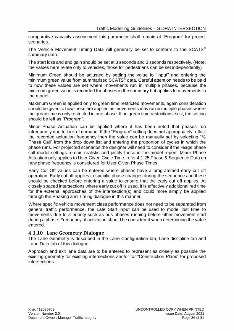
Traffic Modelling Guidelines – SIDRA INTERSECTION
Knet #12035709 UNCONTROLLED COPY WHEN PRINTED Version Number 2.0 Issue Date: August 2021 Document Owner: Manager Traffic Integrity Page 36 of 81
comparative capacity assessment this parameter shall remain at “Program” for project scenarios.
The Vehicle Movement Timing Data will generally be set to conform to the SCATS® summary data.
The start loss and end gain should be set at 3 seconds and 3 seconds respectively. (Note: the values here relate only to vehicles, those for pedestrians can be set independently)
Minimum Green should be adjusted by setting the value to “Input” and entering the minimum green value from summarised SCATS® data. Careful attention needs to be paid to how these values are set where movements run in multiple phases, because the minimum green value is recorded for phases in the summary but applies to movements in the model.
Maximum Green is applied only to green time restricted movements, again consideration should be given to how these are applied as movements may run in multiple phases where the green time is only restricted in one phase. If no green time restrictions exist, the setting should be left as “Program”.
Minor Phase Actuation can be applied where it has been noted that phases run infrequently due to lack of demand. If the “Program” setting does not appropriately reflect the recorded actuation frequency then the value can be manually set by selecting “% Phase Call” from the drop down list and entering the proportion of cycles in which the phase runs. For projected scenarios the designer will need to consider if the %age phase call model settings remain realistic and justify these in the model report. Minor Phase Actuation only applies to User Given Cycle Time, refer 4.1.25 Phase & Sequence Data on how phase frequency is considered for User Given Phase Times.
Early Cut Off values can be entered where phases have a programmed early cut off operation. Early cut off applies to specific phase changes during the sequence and these should be checked before entering a value to ensure that the early cut off applies. At closely spaced intersections where early cut off is used, it is effectively additional red time for the external approaches of the intersection(s) and could more simply be applied through the Phasing and Timing dialogue in this manner.
Where specific vehicle movement class performance does not need to be separated from general traffic performance, the Late Start input can be used to model lost time to movements due to a priority such as bus phases running before other movement start during a phase. Frequency of activation should be considered when determining the value entered.
4.1.10 Lane Geometry Dialogue The Lane Geometry is described in the Lane Configuration tab, Lane discipline tab and Lane Data tab of this dialogue.
Approach and exit lane data are to be entered to represent as closely as possible the existing geometry for existing intersections and/or for “Construction Plans” for proposed intersections.
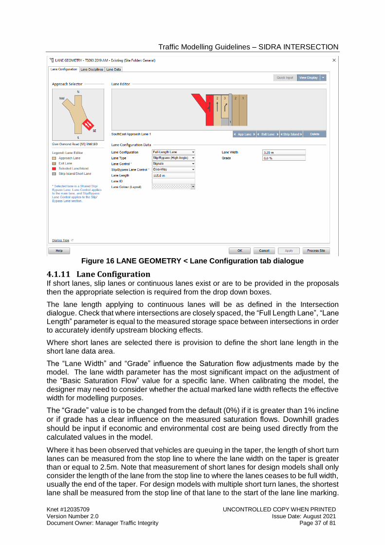
Traffic Modelling Guidelines – SIDRA INTERSECTION
Knet #12035709 UNCONTROLLED COPY WHEN PRINTED Version Number 2.0 Issue Date: August 2021 Document Owner: Manager Traffic Integrity Page 37 of 81
Figure 16 LANE GEOMETRY < Lane Configuration tab dialogue
4.1.11 Lane Configuration If short lanes, slip lanes or continuous lanes exist or are to be provided in the proposals then the appropriate selection is required from the drop down boxes.
The lane length applying to continuous lanes will be as defined in the Intersection dialogue. Check that where intersections are closely spaced, the “Full Length Lane”, “Lane Length” parameter is equal to the measured storage space between intersections in order to accurately identify upstream blocking effects.
Where short lanes are selected there is provision to define the short lane length in the short lane data area.
The “Lane Width” and “Grade” influence the Saturation flow adjustments made by the model. The lane width parameter has the most significant impact on the adjustment of the “Basic Saturation Flow” value for a specific lane. When calibrating the model, the designer may need to consider whether the actual marked lane width reflects the effective width for modelling purposes.
The “Grade” value is to be changed from the default (0%) if it is greater than 1% incline or if grade has a clear influence on the measured saturation flows. Downhill grades should be input if economic and environmental cost are being used directly from the calculated values in the model.
Where it has been observed that vehicles are queuing in the taper, the length of short turn lanes can be measured from the stop line to where the lane width on the taper is greater than or equal to 2.5m. Note that measurement of short lanes for design models shall only consider the length of the lane from the stop line to where the lanes ceases to be full width, usually the end of the taper. For design models with multiple short turn lanes, the shortest lane shall be measured from the stop line of that lane to the start of the lane line marking.
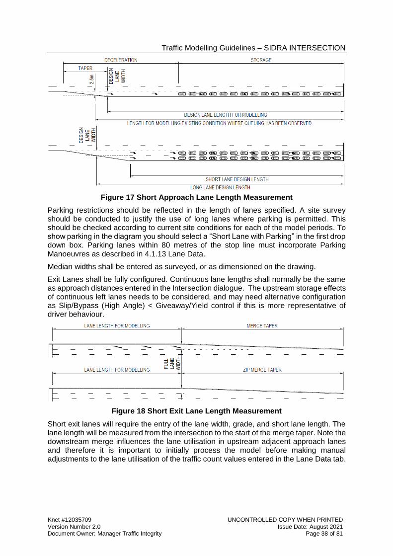
Traffic Modelling Guidelines – SIDRA INTERSECTION
Knet #12035709 UNCONTROLLED COPY WHEN PRINTED Version Number 2.0 Issue Date: August 2021 Document Owner: Manager Traffic Integrity Page 38 of 81
Figure 17 Short Approach Lane Length Measurement
Parking restrictions should be reflected in the length of lanes specified. A site survey should be conducted to justify the use of long lanes where parking is permitted. This should be checked according to current site conditions for each of the model periods. To show parking in the diagram you should select a “Short Lane with Parking” in the first drop down box. Parking lanes within 80 metres of the stop line must incorporate Parking Manoeuvres as described in 4.1.13 Lane Data.
Median widths shall be entered as surveyed, or as dimensioned on the drawing.
Exit Lanes shall be fully configured. Continuous lane lengths shall normally be the same as approach distances entered in the Intersection dialogue. The upstream storage effects of continuous left lanes needs to be considered, and may need alternative configuration as Slip/Bypass (High Angle) < Giveaway/Yield control if this is more representative of driver behaviour.
Figure 18 Short Exit Lane Length Measurement
Short exit lanes will require the entry of the lane width, grade, and short lane length. The lane length will be measured from the intersection to the start of the merge taper. Note the downstream merge influences the lane utilisation in upstream adjacent approach lanes and therefore it is important to initially process the model before making manual adjustments to the lane utilisation of the traffic count values entered in the Lane Data tab.
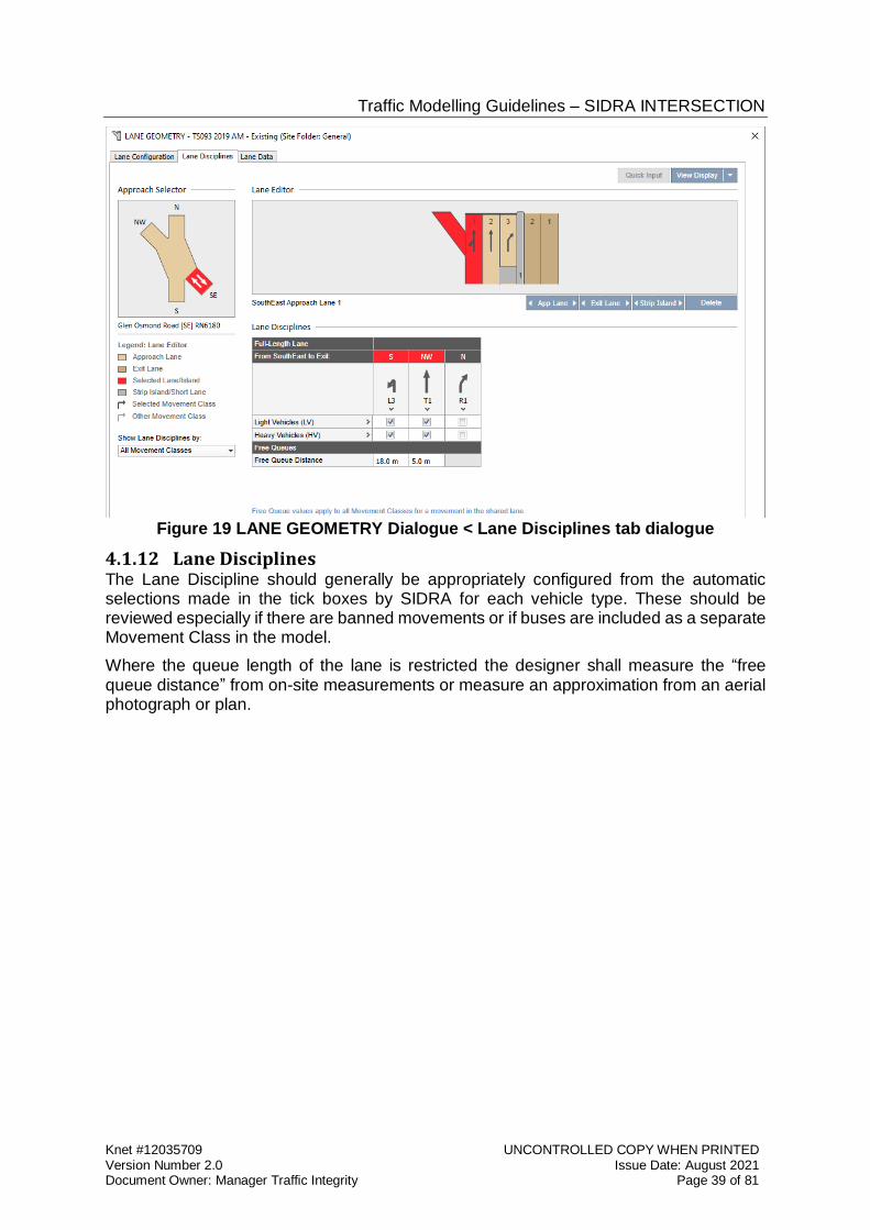
Traffic Modelling Guidelines – SIDRA INTERSECTION
Knet #12035709 UNCONTROLLED COPY WHEN PRINTED Version Number 2.0 Issue Date: August 2021 Document Owner: Manager Traffic Integrity Page 39 of 81
Figure 19 LANE GEOMETRY Dialogue < Lane Disciplines tab dialogue
4.1.12 Lane Disciplines The Lane Discipline should generally be appropriately configured from the automatic selections made in the tick boxes by SIDRA for each vehicle type. These should be reviewed especially if there are banned movements or if buses are included as a separate Movement Class in the model.
Where the queue length of the lane is restricted the designer shall measure the “free queue distance” from on-site measurements or measure an approximation from an aerial photograph or plan.
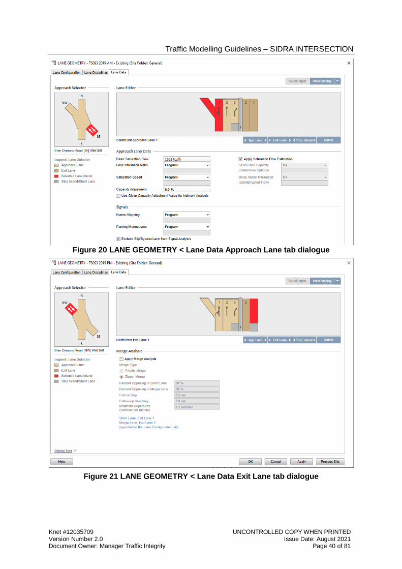
Traffic Modelling Guidelines – SIDRA INTERSECTION
Knet #12035709 UNCONTROLLED COPY WHEN PRINTED Version Number 2.0 Issue Date: August 2021 Document Owner: Manager Traffic Integrity Page 40 of 81
Figure 20 LANE GEOMETRY < Lane Data Approach Lane tab dialogue
Figure 21 LANE GEOMETRY < Lane Data Exit Lane tab dialogue
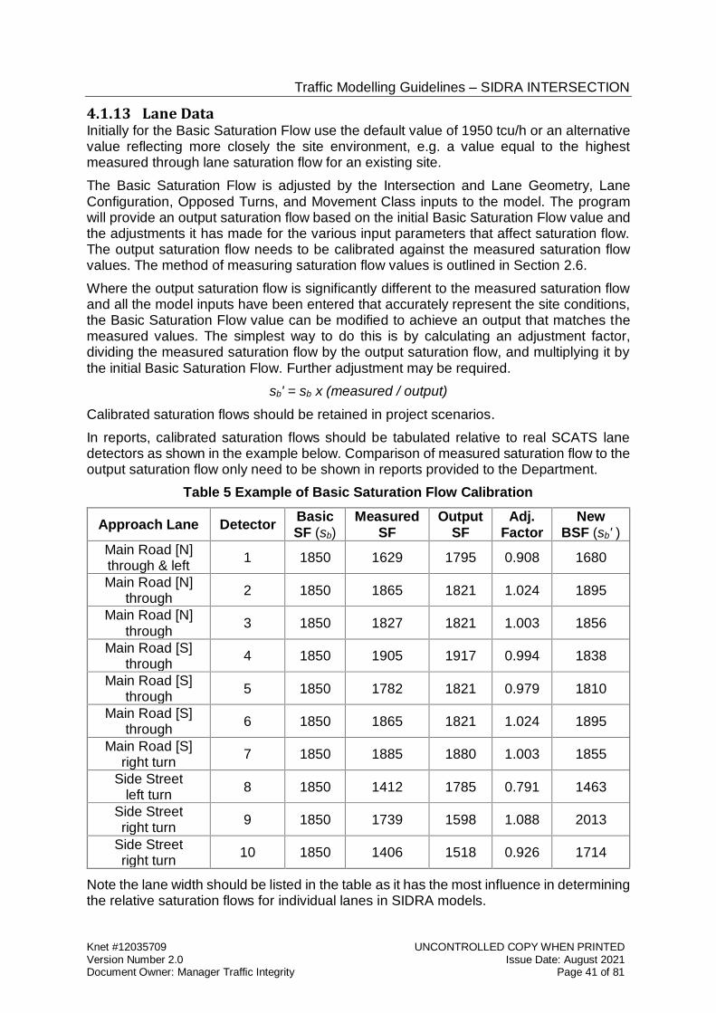
Traffic Modelling Guidelines – SIDRA INTERSECTION
Knet #12035709 UNCONTROLLED COPY WHEN PRINTED Version Number 2.0 Issue Date: August 2021 Document Owner: Manager Traffic Integrity Page 41 of 81
4.1.13 Lane Data Initially for the Basic Saturation Flow use the default value of 1950 tcu/h or an alternative value reflecting more closely the site environment, e.g. a value equal to the highest measured through lane saturation flow for an existing site.
The Basic Saturation Flow is adjusted by the Intersection and Lane Geometry, Lane Configuration, Opposed Turns, and Movement Class inputs to the model. The program will provide an output saturation flow based on the initial Basic Saturation Flow value and the adjustments it has made for the various input parameters that affect saturation flow. The output saturation flow needs to be calibrated against the measured saturation flow values. The method of measuring saturation flow values is outlined in Section 2.6.
Where the output saturation flow is significantly different to the measured saturation flow and all the model inputs have been entered that accurately represent the site conditions, the Basic Saturation Flow value can be modified to achieve an output that matches the measured values. The simplest way to do this is by calculating an adjustment factor, dividing the measured saturation flow by the output saturation flow, and multiplying it by the initial Basic Saturation Flow. Further adjustment may be required.
sb' = sb x (measured / output)
Calibrated saturation flows should be retained in project scenarios.
In reports, calibrated saturation flows should be tabulated relative to real SCATS lane detectors as shown in the example below. Comparison of measured saturation flow to the output saturation flow only need to be shown in reports provided to the Department.
Table 5 Example of Basic Saturation Flow Calibration
Approach Lane Detector Basic SF (sb)
Measured SF
Output SF
Adj. Factor
New BSF (sb' )
Main Road [N] through & left
1 1850 1629 1795 0.908 1680
Main Road [N] through
2 1850 1865 1821 1.024 1895
Main Road [N] through
3 1850 1827 1821 1.003 1856
Main Road [S] through
4 1850 1905 1917 0.994 1838
Main Road [S] through
5 1850 1782 1821 0.979 1810
Main Road [S] through
6 1850 1865 1821 1.024 1895
Main Road [S] right turn
7 1850 1885 1880 1.003 1855
Side Street left turn
8 1850 1412 1785 0.791 1463
Side Street right turn
9 1850 1739 1598 1.088 2013
Side Street right turn
10 1850 1406 1518 0.926 1714
Note the lane width should be listed in the table as it has the most influence in determining the relative saturation flows for individual lanes in SIDRA models.
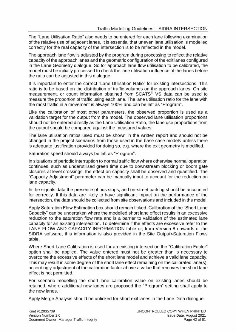
Traffic Modelling Guidelines – SIDRA INTERSECTION
Knet #12035709 UNCONTROLLED COPY WHEN PRINTED Version Number 2.0 Issue Date: August 2021 Document Owner: Manager Traffic Integrity Page 42 of 81
The “Lane Utilisation Ratio” also needs to be entered for each lane following examination of the relative use of adjacent lanes. It is essential that uneven lane utilisation is modelled correctly for the real capacity of the intersection is to be reflected in the model.
The approach lane flow is adjusted by the program during processing to reflect the relative capacity of the approach lanes and the geometric configuration of the exit lanes configured in the Lane Geometry dialogue. So for approach lane flow utilisation to be calibrated, the model must be initially processed to check the lane utilisation influence of the lanes before the ratio can be adjusted in this dialogue.
It is important to enter the correct “Lane Utilisation Ratio” for existing intersections. This ratio is to be based on the distribution of traffic volumes on the approach lanes. On-site measurement, or count information obtained from SCATS® VS data can be used to measure the proportion of traffic using each lane. The lane utilisation ratio for the lane with the most traffic in a movement is always 100% and can be left as “Program”.
Like the calibration of most other parameters, the observed proportion is used as a validation target for the output from the model. The observed lane utilisation proportions should not be entered directly as the Lane Utilisation Ratio, the lane use proportions from the output should be compared against the measured values.
The lane utilisation ratios used must be shown in the written report and should not be changed in the project scenarios from those used in the base case models unless there is adequate justification provided for doing so, e.g. where the exit geometry is modified.
Saturation speed should always be left as “Program”.
In situations of periodic interruption to normal traffic flow where otherwise normal operation continues, such as underutilised green time due to downstream blocking or boom gate closures at level crossings, the effect on capacity shall be observed and quantified. The “Capacity Adjustment” parameter can be manually input to account for the reduction on lane capacity.
In the signals data the presence of bus stops, and on-street parking should be accounted for correctly. If this data are likely to have significant impact on the performance of the intersection, the data should be collected from site observations and included in the model.
Apply Saturation Flow Estimation box should remain ticked. Calibration of the “Short Lane Capacity” can be undertaken where the modelled short lane effect results in an excessive reduction to the saturation flow rate and is a barrier to validation of the estimated lane capacity for an existing intersection. To determine if the effects are excessive refer to the LANE FLOW AND CAPACITY INFORMATION table or, from Version 8 onwards of the SIDRA software, this information is also provided in the Site Output<Saturation Flows table.
Where Short Lane Calibration is used for an existing intersection the “Calibration Factor” option shall be applied. The value entered must not be greater than is necessary to overcome the excessive effects of the short lane model and achieve a valid lane capacity. This may result in some degree of the short lane effect remaining on the calibrated lane(s), accordingly adjustment of the calibration factor above a value that removes the short lane effect is not permitted.
For scenario modelling the short lane calibration value on existing lanes should be retained, where additional new lanes are proposed the “Program” setting shall apply to the new lanes.
Apply Merge Analysis should be unticked for short exit lanes in the Lane Data dialogue.
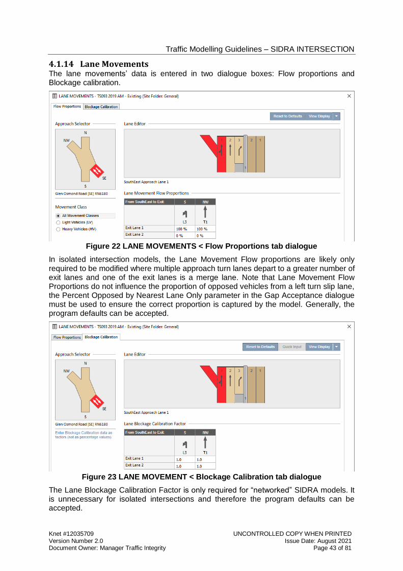
Traffic Modelling Guidelines – SIDRA INTERSECTION
Knet #12035709 UNCONTROLLED COPY WHEN PRINTED Version Number 2.0 Issue Date: August 2021 Document Owner: Manager Traffic Integrity Page 43 of 81
4.1.14 Lane Movements The lane movements’ data is entered in two dialogue boxes: Flow proportions and Blockage calibration.
Figure 22 LANE MOVEMENTS < Flow Proportions tab dialogue
In isolated intersection models, the Lane Movement Flow proportions are likely only required to be modified where multiple approach turn lanes depart to a greater number of exit lanes and one of the exit lanes is a merge lane. Note that Lane Movement Flow Proportions do not influence the proportion of opposed vehicles from a left turn slip lane, the Percent Opposed by Nearest Lane Only parameter in the Gap Acceptance dialogue must be used to ensure the correct proportion is captured by the model. Generally, the program defaults can be accepted.
Figure 23 LANE MOVEMENT < Blockage Calibration tab dialogue
The Lane Blockage Calibration Factor is only required for “networked” SIDRA models. It is unnecessary for isolated intersections and therefore the program defaults can be accepted.
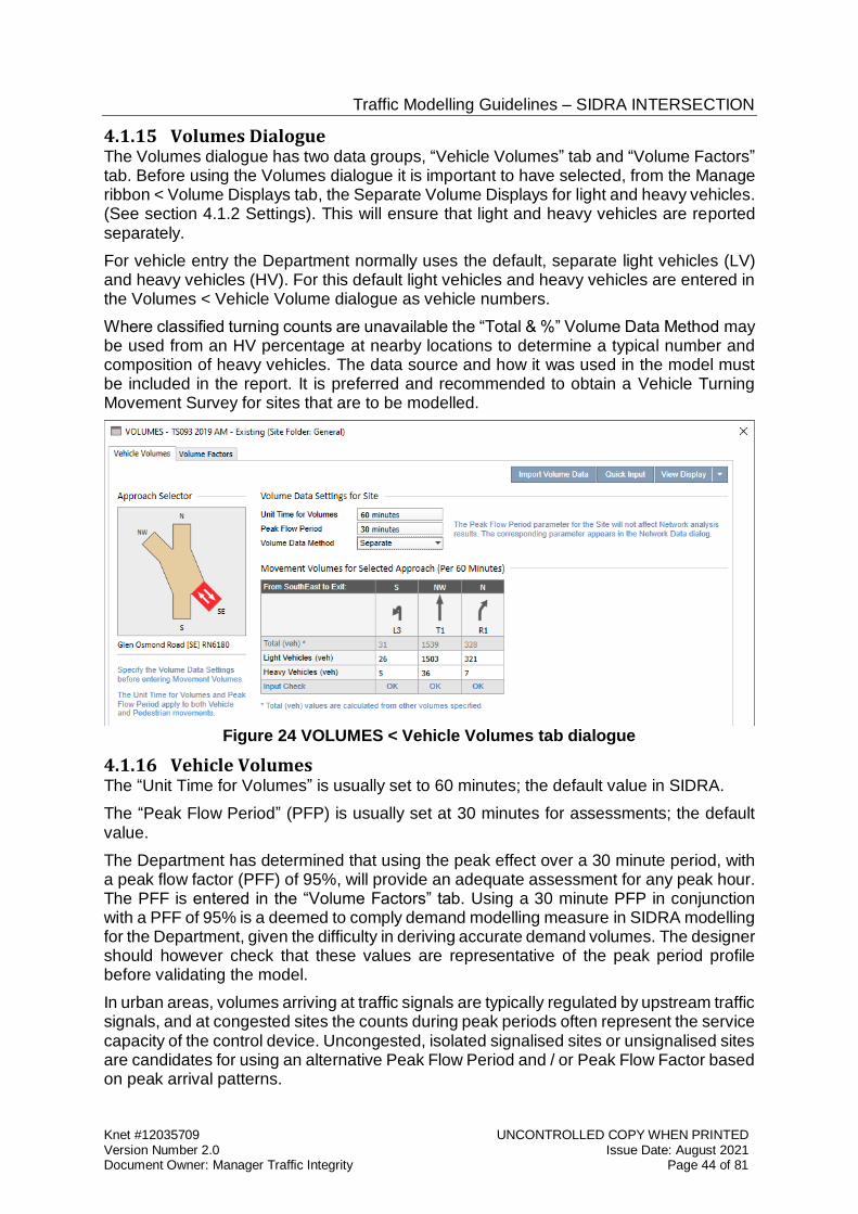
Traffic Modelling Guidelines – SIDRA INTERSECTION
Knet #12035709 UNCONTROLLED COPY WHEN PRINTED Version Number 2.0 Issue Date: August 2021 Document Owner: Manager Traffic Integrity Page 44 of 81
4.1.15 Volumes Dialogue The Volumes dialogue has two data groups, “Vehicle Volumes” tab and “Volume Factors” tab. Before using the Volumes dialogue it is important to have selected, from the Manage ribbon < Volume Displays tab, the Separate Volume Displays for light and heavy vehicles. (See section 4.1.2 Settings). This will ensure that light and heavy vehicles are reported separately.
For vehicle entry the Department normally uses the default, separate light vehicles (LV) and heavy vehicles (HV). For this default light vehicles and heavy vehicles are entered in the Volumes < Vehicle Volume dialogue as vehicle numbers.
Where classified turning counts are unavailable the “Total & %” Volume Data Method may be used from an HV percentage at nearby locations to determine a typical number and composition of heavy vehicles. The data source and how it was used in the model must be included in the report. It is preferred and recommended to obtain a Vehicle Turning Movement Survey for sites that are to be modelled.
Figure 24 VOLUMES < Vehicle Volumes tab dialogue
4.1.16 Vehicle Volumes The “Unit Time for Volumes” is usually set to 60 minutes; the default value in SIDRA.
The “Peak Flow Period” (PFP) is usually set at 30 minutes for assessments; the default value.
The Department has determined that using the peak effect over a 30 minute period, with a peak flow factor (PFF) of 95%, will provide an adequate assessment for any peak hour. The PFF is entered in the “Volume Factors” tab. Using a 30 minute PFP in conjunction with a PFF of 95% is a deemed to comply demand modelling measure in SIDRA modelling for the Department, given the difficulty in deriving accurate demand volumes. The designer should however check that these values are representative of the peak period profile before validating the model.
In urban areas, volumes arriving at traffic signals are typically regulated by upstream traffic signals, and at congested sites the counts during peak periods often represent the service capacity of the control device. Uncongested, isolated signalised sites or unsignalised sites are candidates for using an alternative Peak Flow Period and / or Peak Flow Factor based on peak arrival patterns.
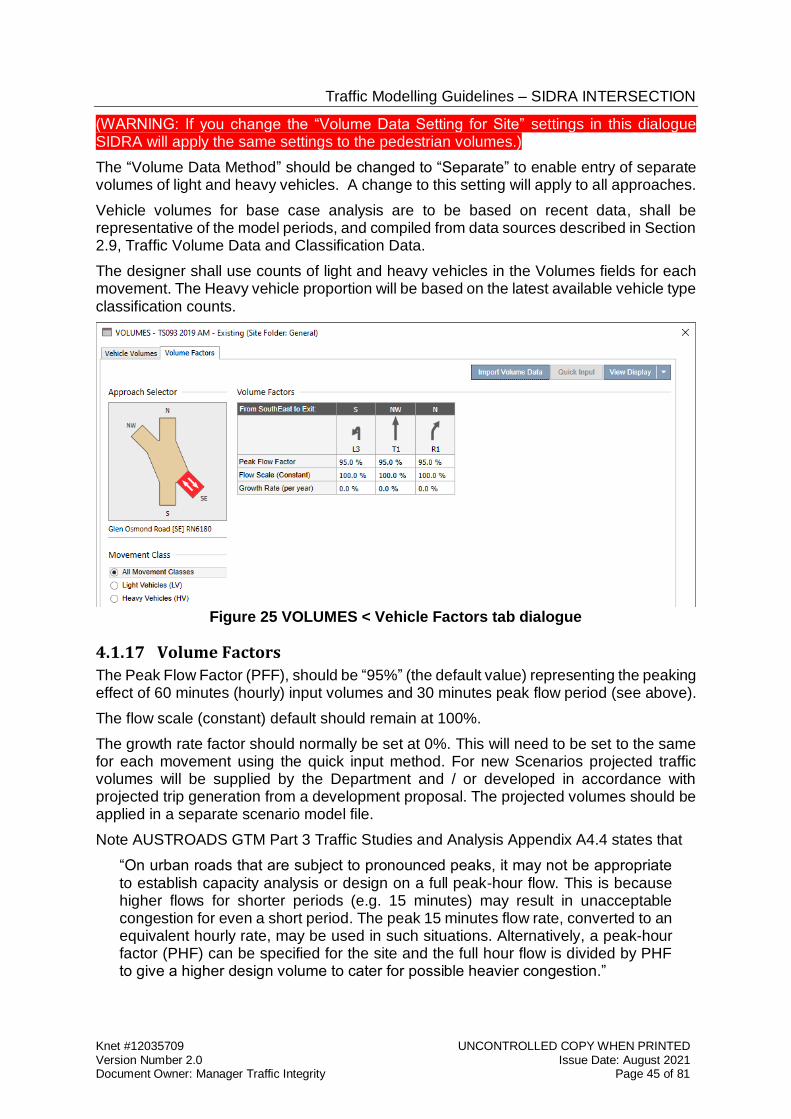
Traffic Modelling Guidelines – SIDRA INTERSECTION
Knet #12035709 UNCONTROLLED COPY WHEN PRINTED Version Number 2.0 Issue Date: August 2021 Document Owner: Manager Traffic Integrity Page 45 of 81
(WARNING: If you change the “Volume Data Setting for Site” settings in this dialogue SIDRA will apply the same settings to the pedestrian volumes.)
The “Volume Data Method” should be changed to “Separate” to enable entry of separate volumes of light and heavy vehicles. A change to this setting will apply to all approaches.
Vehicle volumes for base case analysis are to be based on recent data, shall be representative of the model periods, and compiled from data sources described in Section 2.9, Traffic Volume Data and Classification Data.
The designer shall use counts of light and heavy vehicles in the Volumes fields for each movement. The Heavy vehicle proportion will be based on the latest available vehicle type classification counts.
Figure 25 VOLUMES < Vehicle Factors tab dialogue
4.1.17 Volume Factors
The Peak Flow Factor (PFF), should be “95%” (the default value) representing the peaking effect of 60 minutes (hourly) input volumes and 30 minutes peak flow period (see above).
The flow scale (constant) default should remain at 100%.
The growth rate factor should normally be set at 0%. This will need to be set to the same for each movement using the quick input method. For new Scenarios projected traffic volumes will be supplied by the Department and / or developed in accordance with projected trip generation from a development proposal. The projected volumes should be applied in a separate scenario model file.
Note AUSTROADS GTM Part 3 Traffic Studies and Analysis Appendix A4.4 states that
“On urban roads that are subject to pronounced peaks, it may not be appropriate to establish capacity analysis or design on a full peak-hour flow. This is because higher flows for shorter periods (e.g. 15 minutes) may result in unacceptable congestion for even a short period. The peak 15 minutes flow rate, converted to an equivalent hourly rate, may be used in such situations. Alternatively, a peak-hour factor (PHF) can be specified for the site and the full hour flow is divided by PHF to give a higher design volume to cater for possible heavier congestion.”
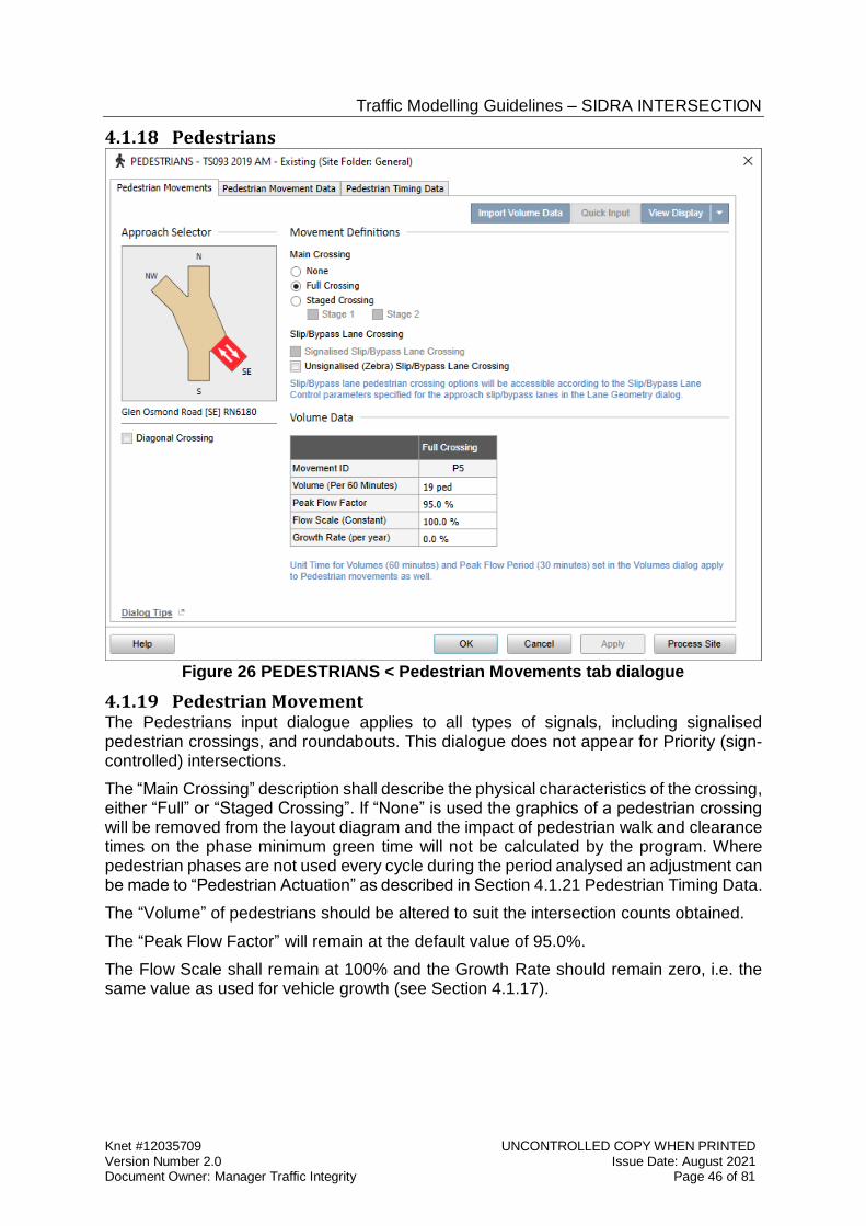
Traffic Modelling Guidelines – SIDRA INTERSECTION
Knet #12035709 UNCONTROLLED COPY WHEN PRINTED Version Number 2.0 Issue Date: August 2021 Document Owner: Manager Traffic Integrity Page 46 of 81
4.1.18 Pedestrians
Figure 26 PEDESTRIANS < Pedestrian Movements tab dialogue
4.1.19 Pedestrian Movement The Pedestrians input dialogue applies to all types of signals, including signalised pedestrian crossings, and roundabouts. This dialogue does not appear for Priority (sign-controlled) intersections.
The “Main Crossing” description shall describe the physical characteristics of the crossing, either “Full” or “Staged Crossing”. If “None” is used the graphics of a pedestrian crossing will be removed from the layout diagram and the impact of pedestrian walk and clearance times on the phase minimum green time will not be calculated by the program. Where pedestrian phases are not used every cycle during the period analysed an adjustment can be made to “Pedestrian Actuation” as described in Section 4.1.21 Pedestrian Timing Data.
The “Volume” of pedestrians should be altered to suit the intersection counts obtained.
The “Peak Flow Factor” will remain at the default value of 95.0%.
The Flow Scale shall remain at 100% and the Growth Rate should remain zero, i.e. the same value as used for vehicle growth (see Section 4.1.17).
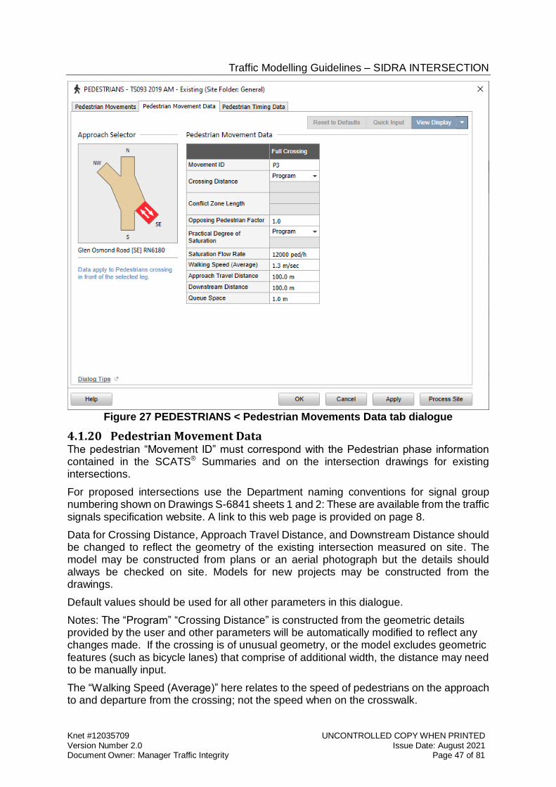
Traffic Modelling Guidelines – SIDRA INTERSECTION
Knet #12035709 UNCONTROLLED COPY WHEN PRINTED Version Number 2.0 Issue Date: August 2021 Document Owner: Manager Traffic Integrity Page 47 of 81
Figure 27 PEDESTRIANS < Pedestrian Movements Data tab dialogue
4.1.20 Pedestrian Movement Data The pedestrian “Movement ID” must correspond with the Pedestrian phase information contained in the SCATS® Summaries and on the intersection drawings for existing intersections.
For proposed intersections use the Department naming conventions for signal group numbering shown on Drawings S-6841 sheets 1 and 2: These are available from the traffic signals specification website. A link to this web page is provided on page 8.
Data for Crossing Distance, Approach Travel Distance, and Downstream Distance should be changed to reflect the geometry of the existing intersection measured on site. The model may be constructed from plans or an aerial photograph but the details should always be checked on site. Models for new projects may be constructed from the drawings.
Default values should be used for all other parameters in this dialogue.
Notes: The “Program” “Crossing Distance” is constructed from the geometric details provided by the user and other parameters will be automatically modified to reflect any changes made. If the crossing is of unusual geometry, or the model excludes geometric features (such as bicycle lanes) that comprise of additional width, the distance may need to be manually input.
The “Walking Speed (Average)” here relates to the speed of pedestrians on the approach to and departure from the crossing; not the speed when on the crosswalk.
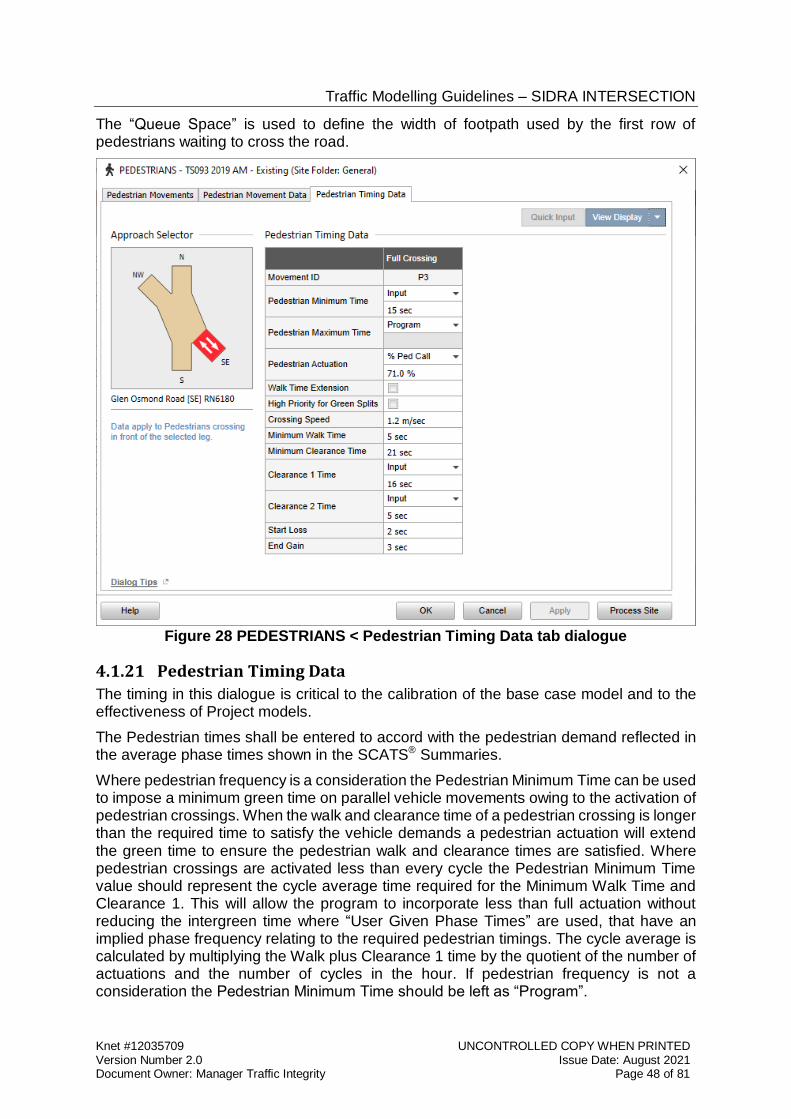
Traffic Modelling Guidelines – SIDRA INTERSECTION
Knet #12035709 UNCONTROLLED COPY WHEN PRINTED Version Number 2.0 Issue Date: August 2021 Document Owner: Manager Traffic Integrity Page 48 of 81
The “Queue Space” is used to define the width of footpath used by the first row of pedestrians waiting to cross the road.
Figure 28 PEDESTRIANS < Pedestrian Timing Data tab dialogue
4.1.21 Pedestrian Timing Data
The timing in this dialogue is critical to the calibration of the base case model and to the effectiveness of Project models.
The Pedestrian times shall be entered to accord with the pedestrian demand reflected in the average phase times shown in the SCATS® Summaries.
Where pedestrian frequency is a consideration the Pedestrian Minimum Time can be used to impose a minimum green time on parallel vehicle movements owing to the activation of pedestrian crossings. When the walk and clearance time of a pedestrian crossing is longer than the required time to satisfy the vehicle demands a pedestrian actuation will extend the green time to ensure the pedestrian walk and clearance times are satisfied. Where pedestrian crossings are activated less than every cycle the Pedestrian Minimum Time value should represent the cycle average time required for the Minimum Walk Time and Clearance 1. This will allow the program to incorporate less than full actuation without reducing the intergreen time where “User Given Phase Times” are used, that have an implied phase frequency relating to the required pedestrian timings. The cycle average is calculated by multiplying the Walk plus Clearance 1 time by the quotient of the number of actuations and the number of cycles in the hour. If pedestrian frequency is not a consideration the Pedestrian Minimum Time should be left as “Program”.
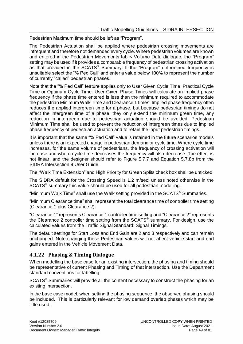
Traffic Modelling Guidelines – SIDRA INTERSECTION
Knet #12035709 UNCONTROLLED COPY WHEN PRINTED Version Number 2.0 Issue Date: August 2021 Document Owner: Manager Traffic Integrity Page 49 of 81
Pedestrian Maximum time should be left as “Program”.
The Pedestrian Actuation shall be applied where pedestrian crossing movements are infrequent and therefore not demanded every cycle. Where pedestrian volumes are known and entered in the Pedestrian Movements tab < Volume Data dialogue, the “Program” setting may be used if it provides a comparable frequency of pedestrian crossing activation as that provided in the SCATS® Summary. If the “Program” determined frequency is unsuitable select the “% Ped Call” and enter a value below 100% to represent the number of currently “called” pedestrian phases.
Note that the “% Ped Call” feature applies only to User Given Cycle Time, Practical Cycle Time or Optimum Cycle Time. User Given Phase Times will calculate an implied phase frequency if the phase time entered is less than the minimum required to accommodate the pedestrian Minimum Walk Time and Clearance 1 times. Implied phase frequency often reduces the applied intergreen time for a phase, but because pedestrian timings do not affect the intergreen time of a phase, they only extend the minimum green time, any reduction in intergreen due to pedestrian actuation should be avoided. Pedestrian Minimum Time shall be used to prevent the reduction of intergreen times due to implied phase frequency of pedestrian actuation and to retain the input pedestrian timings.
It is important that the same “% Ped Call” value is retained in the future scenarios models unless there is an expected change in pedestrian demand or cycle time. Where cycle time increases, for the same volume of pedestrians, the frequency of crossing activation will increase and where cycle time decreases the frequency will also decrease. The effect is not linear, and the designer should refer to Figure 5.7.7 and Equation 5.7.8b from the SIDRA Intersection 9 User Guide.
The “Walk Time Extension” and High Priority for Green Splits check box shall be unticked.
The SIDRA default for the Crossing Speed is 1.2 m/sec; unless noted otherwise in the SCATS® summary this value should be used for all pedestrian modelling.
“Minimum Walk Time” shall use the Walk setting provided in the SCATS® Summaries.
“Minimum Clearance time” shall represent the total clearance time of controller time setting (Clearance 1 plus Clearance 2).
“Clearance 1” represents Clearance 1 controller time setting and “Clearance 2” represents the Clearance 2 controller time setting from the SCATS® summary. For design, use the calculated values from the Traffic Signal Standard: Signal Timings.
The default settings for Start Loss and End Gain are 2 and 3 respectively and can remain unchanged. Note changing these Pedestrian values will not affect vehicle start and end gains entered in the Vehicle Movement Data.
4.1.22 Phasing & Timing Dialogue
When modelling the base case for an existing intersection, the phasing and timing should be representative of current Phasing and Timing of that intersection. Use the Department standard conventions for labelling.
SCATS® Summaries will provide all the content necessary to construct the phasing for an existing intersection.
In the base case model, when setting the phasing sequence, the observed phasing should be included. This is particularly relevant for low demand overlap phases which may be little used.
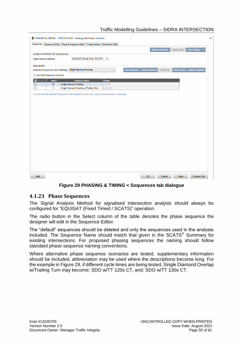
Traffic Modelling Guidelines – SIDRA INTERSECTION
Knet #12035709 UNCONTROLLED COPY WHEN PRINTED Version Number 2.0 Issue Date: August 2021 Document Owner: Manager Traffic Integrity Page 50 of 81
Figure 29 PHASING & TIMING < Sequences tab dialogue
4.1.23 Phase Sequences
The Signal Analysis Method for signalised intersection analysis should always be configured for “EQUISAT (Fixed Timed / SCATS)” operation.
The radio button in the Select column of the table denotes the phase sequence the designer will edit in the Sequence Editor.
The “default” sequences should be deleted and only the sequences used in the analysis included. The Sequence Name should match that given in the SCATS® Summary for existing intersections. For proposed phasing sequences the naming should follow standard phase sequence naming conventions.
Where alternative phase sequence scenarios are tested, supplementary information should be included, abbreviation may be used where the descriptions become long. For the example in Figure 29, if different cycle times are being tested, Single Diamond Overlap w/Trailing Turn may become; SDO w/TT 120s CT, and; SDO w/TT 130s CT.
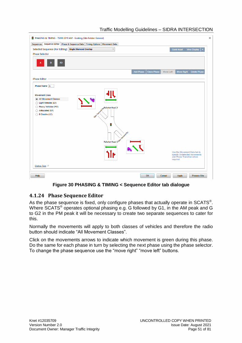
Traffic Modelling Guidelines – SIDRA INTERSECTION
Knet #12035709 UNCONTROLLED COPY WHEN PRINTED Version Number 2.0 Issue Date: August 2021 Document Owner: Manager Traffic Integrity Page 51 of 81
Figure 30 PHASING & TIMING < Sequence Editor tab dialogue
4.1.24 Phase Sequence Editor
As the phase sequence is fixed, only configure phases that actually operate in SCATS®. Where SCATS® operates optional phasing e.g. G followed by G1, in the AM peak and G to G2 in the PM peak it will be necessary to create two separate sequences to cater for this.
Normally the movements will apply to both classes of vehicles and therefore the radio button should indicate “All Movement Classes”.
Click on the movements arrows to indicate which movement is green during this phase. Do the same for each phase in turn by selecting the next phase using the phase selector. To change the phase sequence use the “move right” “move left” buttons.
Traffic Modelling Guidelines – SIDRA INTERSECTION
Knet #12035709 UNCONTROLLED COPY WHEN PRINTED Version Number 2.0 Issue Date: August 2021 Document Owner: Manager Traffic Integrity Page 52 of 81
Figure 31 PHASING & TIMING < Phase & Sequence Data tab dialogue
4.1.25 Phase & Sequence Data
The Variable Phase boxes are not to be ticked in the models reported to the Department. The phase sequence is to reflect the actual phase sequence and signal groups displayed by SCATS®, and is not to be determined by SIDRA. Where overlap phasing sequences are tested using variable phase configurations, the resulting phase sequence should be fixed in the model when provided to the Department.
The reference phase is merely to indicate the phase that is co-ordinated in a SIDRA network model. Although of no significance for individual sites one phase needs to be selected and this should normally represent the SCATS® stretch phase.
To enable entry of the phase time from SCATS Summaries, the “User Given Phase Time” option should be selected in the “Timing Options” tab.
Enter the Phase Times. The phase time is the displayed green time plus intergreen time, where intergreen time is yellow time plus all-red time specified for the phase. For calibration of the saturation flow in the base case, the user must enter the phase times provided in the SCATS® summaries. Phase times should only be modified from those provided in the SCATS® summary as a last resort, once reasonable modifications of the relevant model parameters have been exhausted. Where calibration of the model requires adjustment of the given phase times by more than 3 seconds, the Department shall be notified to review the information used in construction of the model.
In addition where User Given Phase Times have been applied, and are adjusted from the provided phase timings in a SCATS® Summary, checks should be made to ensure phase times do not invalidate the minimum due to required pedestrian times. For pedestrian crossings that are activated every cycle the minimum time is simply the sum of the Walk plus Clearance 1 time for the concurrent pedestrian movement(s) within the phase. If the pedestrian activation frequency is less than 100% then the cycle average minimum shall apply, as a cycle weighted average of the pedestrian minimum time and vehicle minimum
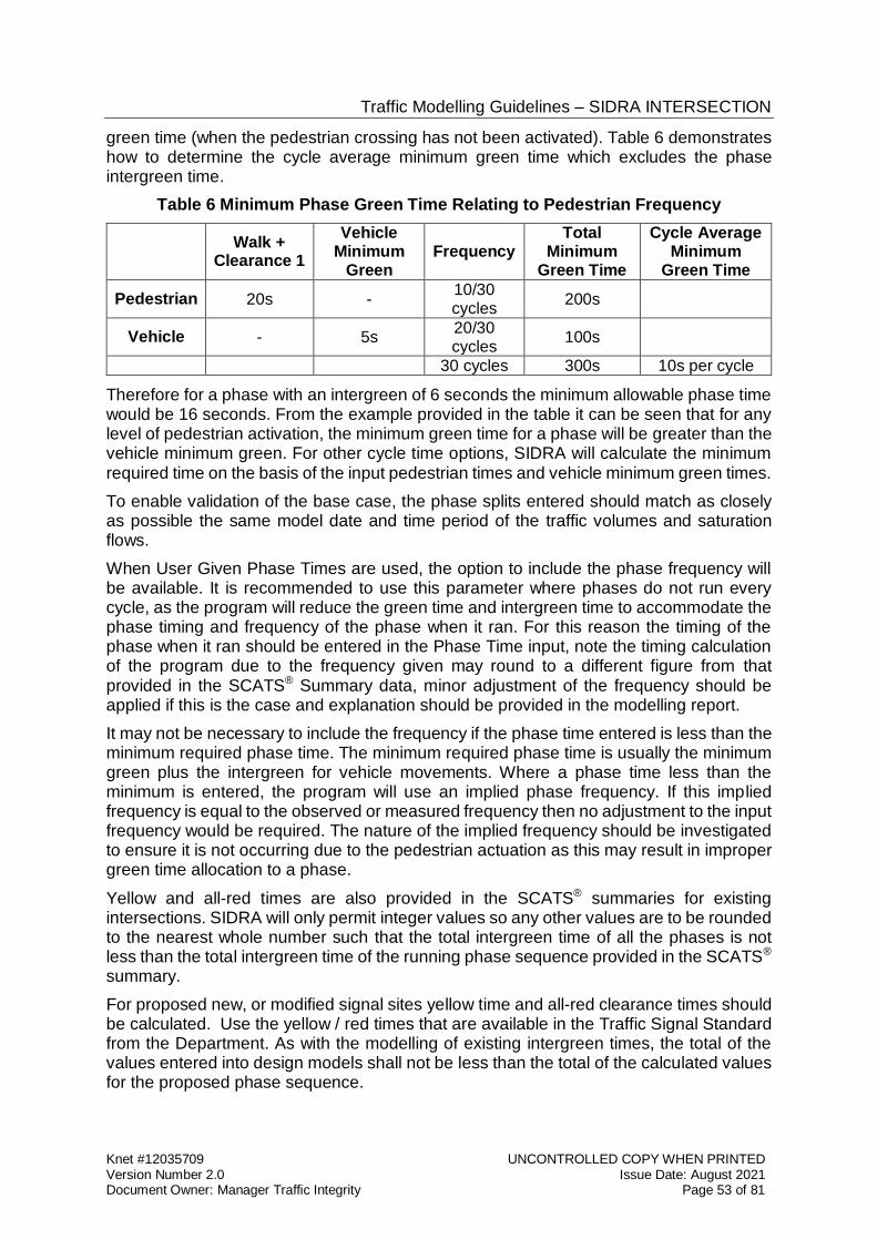
Traffic Modelling Guidelines – SIDRA INTERSECTION
Knet #12035709 UNCONTROLLED COPY WHEN PRINTED Version Number 2.0 Issue Date: August 2021 Document Owner: Manager Traffic Integrity Page 53 of 81
green time (when the pedestrian crossing has not been activated). Table 6 demonstrates how to determine the cycle average minimum green time which excludes the phase intergreen time.
Table 6 Minimum Phase Green Time Relating to Pedestrian Frequency
Walk +
Clearance 1
Vehicle Minimum
Green Frequency
Total Minimum
Green Time
Cycle Average Minimum
Green Time
Pedestrian 20s - 10/30 cycles
200s
Vehicle - 5s 20/30 cycles
100s
30 cycles 300s 10s per cycle
Therefore for a phase with an intergreen of 6 seconds the minimum allowable phase time would be 16 seconds. From the example provided in the table it can be seen that for any level of pedestrian activation, the minimum green time for a phase will be greater than the vehicle minimum green. For other cycle time options, SIDRA will calculate the minimum required time on the basis of the input pedestrian times and vehicle minimum green times.
To enable validation of the base case, the phase splits entered should match as closely as possible the same model date and time period of the traffic volumes and saturation flows.
When User Given Phase Times are used, the option to include the phase frequency will be available. It is recommended to use this parameter where phases do not run every cycle, as the program will reduce the green time and intergreen time to accommodate the phase timing and frequency of the phase when it ran. For this reason the timing of the phase when it ran should be entered in the Phase Time input, note the timing calculation of the program due to the frequency given may round to a different figure from that provided in the SCATS® Summary data, minor adjustment of the frequency should be applied if this is the case and explanation should be provided in the modelling report.
It may not be necessary to include the frequency if the phase time entered is less than the minimum required phase time. The minimum required phase time is usually the minimum green plus the intergreen for vehicle movements. Where a phase time less than the minimum is entered, the program will use an implied phase frequency. If this implied frequency is equal to the observed or measured frequency then no adjustment to the input frequency would be required. The nature of the implied frequency should be investigated to ensure it is not occurring due to the pedestrian actuation as this may result in improper green time allocation to a phase.
Yellow and all-red times are also provided in the SCATS® summaries for existing intersections. SIDRA will only permit integer values so any other values are to be rounded to the nearest whole number such that the total intergreen time of all the phases is not less than the total intergreen time of the running phase sequence provided in the SCATS® summary.
For proposed new, or modified signal sites yellow time and all-red clearance times should be calculated. Use the yellow / red times that are available in the Traffic Signal Standard from the Department. As with the modelling of existing intergreen times, the total of the values entered into design models shall not be less than the total of the calculated values for the proposed phase sequence.
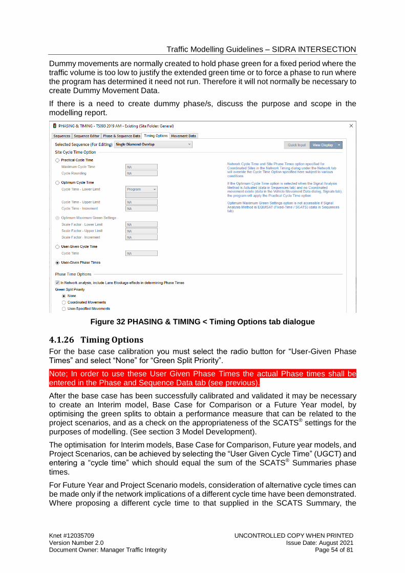
Traffic Modelling Guidelines – SIDRA INTERSECTION
Knet #12035709 UNCONTROLLED COPY WHEN PRINTED Version Number 2.0 Issue Date: August 2021 Document Owner: Manager Traffic Integrity Page 54 of 81
Dummy movements are normally created to hold phase green for a fixed period where the traffic volume is too low to justify the extended green time or to force a phase to run where the program has determined it need not run. Therefore it will not normally be necessary to create Dummy Movement Data.
If there is a need to create dummy phase/s, discuss the purpose and scope in the modelling report.
Figure 32 PHASING & TIMING < Timing Options tab dialogue
4.1.26 Timing Options
For the base case calibration you must select the radio button for “User-Given Phase Times” and select “None” for “Green Split Priority”.
Note; In order to use these User Given Phase Times the actual Phase times shall be entered in the Phase and Sequence Data tab (see previous).
After the base case has been successfully calibrated and validated it may be necessary to create an Interim model, Base Case for Comparison or a Future Year model, by optimising the green splits to obtain a performance measure that can be related to the project scenarios, and as a check on the appropriateness of the SCATS® settings for the purposes of modelling. (See section 3 Model Development).
The optimisation for Interim models, Base Case for Comparison, Future year models, and Project Scenarios, can be achieved by selecting the “User Given Cycle Time” (UGCT) and entering a “cycle time” which should equal the sum of the SCATS® Summaries phase times.
For Future Year and Project Scenario models, consideration of alternative cycle times can be made only if the network implications of a different cycle time have been demonstrated. Where proposing a different cycle time to that supplied in the SCATS Summary, the
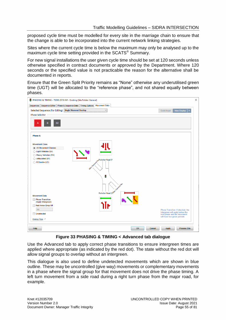
Traffic Modelling Guidelines – SIDRA INTERSECTION
Knet #12035709 UNCONTROLLED COPY WHEN PRINTED Version Number 2.0 Issue Date: August 2021 Document Owner: Manager Traffic Integrity Page 55 of 81
proposed cycle time must be modelled for every site in the marriage chain to ensure that the change is able to be incorporated into the current network linking strategies.
Sites where the current cycle time is below the maximum may only be analysed up to the maximum cycle time setting provided in the SCATS® Summary.
For new signal installations the user given cycle time should be set at 120 seconds unless otherwise specified in contract documents or approved by the Department. Where 120 seconds or the specified value is not practicable the reason for the alternative shall be documented in reports.
Ensure that the Green Split Priority remains as “None” otherwise any underutilised green time (UGT) will be allocated to the “reference phase”, and not shared equally between phases.
Figure 33 PHASING & TIMING < Advanced tab dialogue
Use the Advanced tab to apply correct phase transitions to ensure intergreen times are applied where appropriate (as indicated by the red dot). The state without the red dot will allow signal groups to overlap without an intergreen.
This dialogue is also used to define undetected movements which are shown in blue outline. These may be uncontrolled (give way) movements or complementary movements in a phase where the signal group for that movement does not drive the phase timing. A left turn movement from a side road during a right turn phase from the major road, for example.
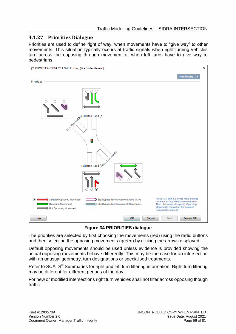
Traffic Modelling Guidelines – SIDRA INTERSECTION
Knet #12035709 UNCONTROLLED COPY WHEN PRINTED Version Number 2.0 Issue Date: August 2021 Document Owner: Manager Traffic Integrity Page 56 of 81
4.1.27 Priorities Dialogue
Priorities are used to define right of way, when movements have to “give way” to other movements. This situation typically occurs at traffic signals when right turning vehicles turn across the opposing through movement or when left turns have to give way to pedestrians.
Figure 34 PRIORITIES dialogue
The priorities are selected by first choosing the movements (red) using the radio buttons and then selecting the opposing movements (green) by clicking the arrows displayed.
Default opposing movements should be used unless evidence is provided showing the actual opposing movements behave differently. This may be the case for an intersection with an unusual geometry, turn designations or specialised treatments.
Refer to SCATS® Summaries for right and left turn filtering information. Right turn filtering may be different for different periods of the day.
For new or modified intersections right turn vehicles shall not filter across opposing though traffic.
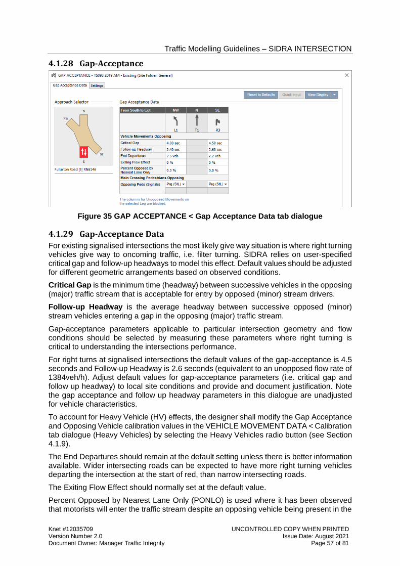
Traffic Modelling Guidelines – SIDRA INTERSECTION
Knet #12035709 UNCONTROLLED COPY WHEN PRINTED Version Number 2.0 Issue Date: August 2021 Document Owner: Manager Traffic Integrity Page 57 of 81
4.1.28 Gap-Acceptance
Figure 35 GAP ACCEPTANCE < Gap Acceptance Data tab dialogue
4.1.29 Gap-Acceptance Data
For existing signalised intersections the most likely give way situation is where right turning vehicles give way to oncoming traffic, i.e. filter turning. SIDRA relies on user-specified critical gap and follow-up headways to model this effect. Default values should be adjusted for different geometric arrangements based on observed conditions.
Critical Gap is the minimum time (headway) between successive vehicles in the opposing (major) traffic stream that is acceptable for entry by opposed (minor) stream drivers.
Follow-up Headway is the average headway between successive opposed (minor) stream vehicles entering a gap in the opposing (major) traffic stream.
Gap-acceptance parameters applicable to particular intersection geometry and flow conditions should be selected by measuring these parameters where right turning is critical to understanding the intersections performance.
For right turns at signalised intersections the default values of the gap-acceptance is 4.5 seconds and Follow-up Headway is 2.6 seconds (equivalent to an unopposed flow rate of 1384veh/h). Adjust default values for gap-acceptance parameters (i.e. critical gap and follow up headway) to local site conditions and provide and document justification. Note the gap acceptance and follow up headway parameters in this dialogue are unadjusted for vehicle characteristics.
To account for Heavy Vehicle (HV) effects, the designer shall modify the Gap Acceptance and Opposing Vehicle calibration values in the VEHICLE MOVEMENT DATA < Calibration tab dialogue (Heavy Vehicles) by selecting the Heavy Vehicles radio button (see Section 4.1.9).
The End Departures should remain at the default setting unless there is better information available. Wider intersecting roads can be expected to have more right turning vehicles departing the intersection at the start of red, than narrow intersecting roads.
The Exiting Flow Effect should normally set at the default value.
Percent Opposed by Nearest Lane Only (PONLO) is used where it has been observed that motorists will enter the traffic stream despite an opposing vehicle being present in the
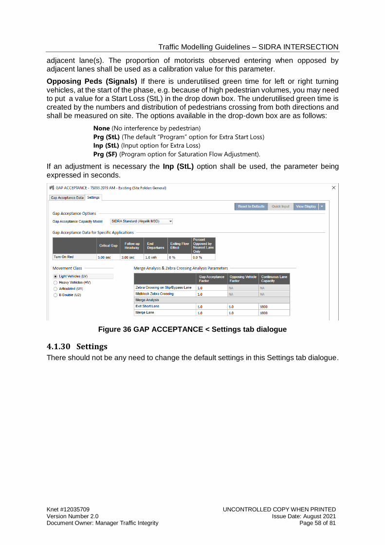
Traffic Modelling Guidelines – SIDRA INTERSECTION
Knet #12035709 UNCONTROLLED COPY WHEN PRINTED Version Number 2.0 Issue Date: August 2021 Document Owner: Manager Traffic Integrity Page 58 of 81
adjacent lane(s). The proportion of motorists observed entering when opposed by adjacent lanes shall be used as a calibration value for this parameter.
Opposing Peds (Signals) If there is underutilised green time for left or right turning vehicles, at the start of the phase, e.g. because of high pedestrian volumes, you may need to put a value for a Start Loss (StL) in the drop down box. The underutilised green time is created by the numbers and distribution of pedestrians crossing from both directions and shall be measured on site. The options available in the drop-down box are as follows:
None (No interference by pedestrian)
Prg (StL) (The default “Program” option for Extra Start Loss)
Inp (StL) (Input option for Extra Loss)
Prg (SF) (Program option for Saturation Flow Adjustment).
If an adjustment is necessary the Inp (StL) option shall be used, the parameter being expressed in seconds.
Figure 36 GAP ACCEPTANCE < Settings tab dialogue
4.1.30 Settings
There should not be any need to change the default settings in this Settings tab dialogue.
Traffic Modelling Guidelines – SIDRA INTERSECTION
Knet #12035709 UNCONTROLLED COPY WHEN PRINTED Version Number 2.0 Issue Date: August 2021 Document Owner: Manager Traffic Integrity Page 59 of 81
4.2 Proposed Scenario Models SIDRA models of proposed scenarios are created by cloning and modifying any of the base case, interim, base case for comparison or Future Year models. All these models are derivatives of calibrated and validated base case models, and are suitable for comparison with project scenarios dependent on the specific needs of the project
Consideration needs to be had in each scenario of proposed changes to the following:
the physical intersection geometry,
traffic signal controls and operation, and
The future year traffic flow volumes.
4.2.1 Proposed Geometric Changes
Modified intersections are created from existing road geometry reflected in the base case model and interim models. Care should be taken that the traffic characteristics (e.g. saturation flows) of additional lanes or modified lanes reflect similar characteristics to the existing intersection.
For new intersections ensure that the models represent realistic designs. Saturation flows should be representative of the geographical location or similar environment, e.g. city centre / suburban. Typical measured saturation flow values from adjacent intersections will form a good basis for an initial “basic saturation flow” parameter for through lanes. (See Section 3.3.1 Calibration and Section 4.1.13 Lane Data).
Intersection layouts must be designed to provide the most flexible signal operation possible. Opposed right turns should be designed to run concurrently to allow diamond right turn operation. Shared lanes shall not be used. Split-approach phasing should be avoided unless the benefits of increased capacity and reduced delays can be demonstrated for the whole of day operations. To assess whole of day operations the designer may require additional model periods for completeness.
If the intersection is to be used by large vehicles ensure that the minimum green time settings and intergreen clearances are appropriate and in accordance with NTC guidelines. The Department Traffic Signal Standard: Signal Timings provides how these are accounted for at intersections in accordance with the Department and National freight network. Ensure that the swept paths are suitable to ensure the turns do not need to be traversed at restricted speeds which will affect model assumptions.
In developing turning bays ensure that they are long enough to be used effectively. Do not extend or reduce the cycle length or phase times to make the queue fit the geometry.
Increased pedestrian delays may result from your proposal. Consider the means of alleviating these delays which might include, staged crossings, wider crossings, and or a combination of these measures.
Assume that all right turn movements are fully controlled.
4.2.2 Proposed Phase Arrangements
For existing intersections which are proposed to be modified, the project scenario models will be created from the calibrated and validated base case, interim or base case for comparison model. The parameters are to remain unchanged except those pertinent to the represent the proposal. Only the final proposal need be presented and reported to the
Traffic Modelling Guidelines – SIDRA INTERSECTION
Knet #12035709 UNCONTROLLED COPY WHEN PRINTED Version Number 2.0 Issue Date: August 2021 Document Owner: Manager Traffic Integrity Page 60 of 81
Department but shall be in the form of a fixed “User Given Cycle Time” length and fixed phase sequence.
For projected intersections, the phasing arrangements, phase sequence options and time settings for new signalised intersections should be designed in accordance with the Department standards shown in the Department Standard Drawing 6841 Sheets 1 and 2, “Traffic Signals Design Guide Detectors Signal Groups Phasing and Pole Numbering Standards”
Where an intersection is part of a SCATS® grouping, the cycle time is generally controlled by the SCATS® master subsystem. [i.e. A site with Offset Plan values set at 0 and having no link offsets, but to which other sites link]. The designer shall use the grouping cycle time as the “User Given Cycle Time” for analysis of proposed or modified intersections included in this system. (See link to the Department RD-EL-D2 Traffic Signals Design specification webpage on page 8)
Where no cycle length can be determined from existing SCATS® settings the acceptable “User Given Cycle Time” length for new traffic signals is 120 seconds.
In the PHASING AND TIMING dialogue boxes the designer shall ensure that the model selections provide practical outcomes which can be programmed in the controller and set up in SCATS®. Operational economies in the design are not permitted.
Intergreen times shall be designed in accordance with the Department Traffic Signal Standard. Minimum green times shall accord with the National Heavy Vehicles Register report “NTC Performance Based Standards Scheme - Network Classification Performance4 for intersections as identified in the Traffic Signal Standard document.
With respect to pedestrian phases, as outlined in the notes on preparing the base case model, the pedestrian time should reflect the average use of the pedestrian phase times and shall be adjusted by the use of the “Pedestrian Activation” %age Ped Call (see Section 4.1.21 Pedestrian Timing Data, Page 48).
Approach arrival types for signal co-ordination effects should always be set at “Program”, the default of which is isolated (type 3).
The designer shall determine the most appropriate phasing arrangement to suit the new geometry being proposed.
The phasing of the proposed intersection shall not include:
Right turn filtering.
Shared lanes i.e. left and through movements or right and through movements in the same lane.
Left turn on red permitted after stopping.
Phase skipping.
If the intersection is in an area of high pedestrian usage ensure that the pedestrian phase duration times are representative of the demand. In the first instance assume time settings that represent the design values for pedestrian clearances.
4 National Heavy Vehicle Register, National Transport Commission – Performance – Based Standards Scheme – Network Classification Guidelines July 2007.
Traffic Modelling Guidelines – SIDRA INTERSECTION
Knet #12035709 UNCONTROLLED COPY WHEN PRINTED Version Number 2.0 Issue Date: August 2021 Document Owner: Manager Traffic Integrity Page 61 of 81
4.2.3 Future Year Traffic Volumes
The future year traffic volumes will be normally be provided as part of a specification or client brief, and may represent different projected development and population projections. For developer initiated proposals projected volumes shall be subject to prior approval of the Department before commencement of scenario modelling.
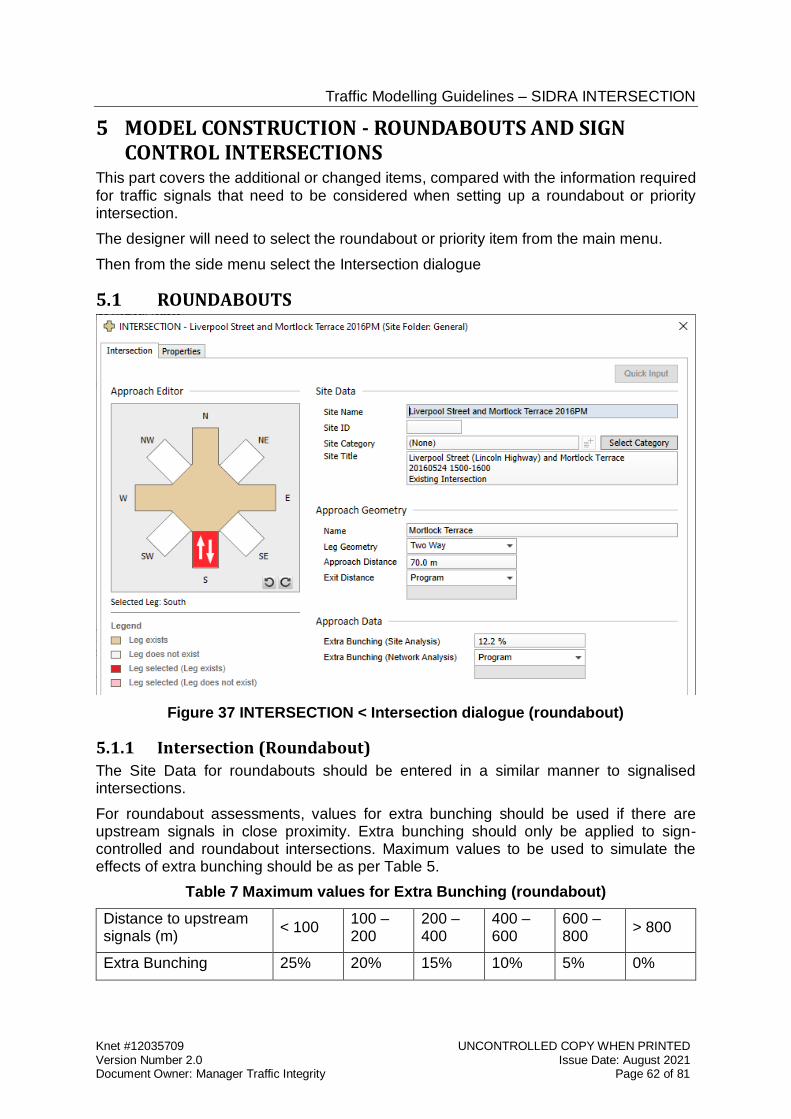
Traffic Modelling Guidelines – SIDRA INTERSECTION
Knet #12035709 UNCONTROLLED COPY WHEN PRINTED Version Number 2.0 Issue Date: August 2021 Document Owner: Manager Traffic Integrity Page 62 of 81
5 MODEL CONSTRUCTION - ROUNDABOUTS AND SIGN CONTROL INTERSECTIONS
This part covers the additional or changed items, compared with the information required for traffic signals that need to be considered when setting up a roundabout or priority intersection.
The designer will need to select the roundabout or priority item from the main menu.
Then from the side menu select the Intersection dialogue
5.1 ROUNDABOUTS
Figure 37 INTERSECTION < Intersection dialogue (roundabout)
5.1.1 Intersection (Roundabout)
The Site Data for roundabouts should be entered in a similar manner to signalised intersections.
For roundabout assessments, values for extra bunching should be used if there are upstream signals in close proximity. Extra bunching should only be applied to sign-controlled and roundabout intersections. Maximum values to be used to simulate the effects of extra bunching should be as per Table 5.
Table 7 Maximum values for Extra Bunching (roundabout)
Distance to upstream signals (m)
< 100 100 – 200
200 – 400
400 – 600
600 – 800
> 800
Extra Bunching 25% 20% 15% 10% 5% 0%
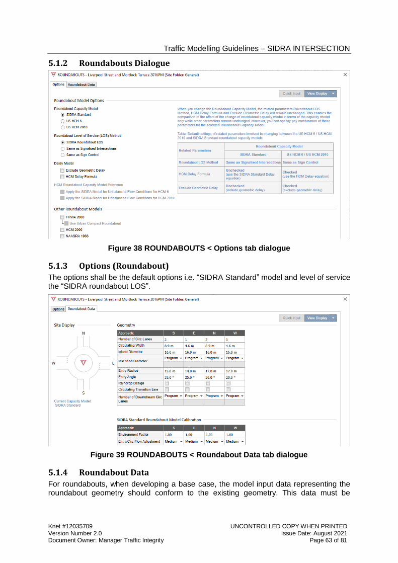
Traffic Modelling Guidelines – SIDRA INTERSECTION
Knet #12035709 UNCONTROLLED COPY WHEN PRINTED Version Number 2.0 Issue Date: August 2021 Document Owner: Manager Traffic Integrity Page 63 of 81
5.1.2 Roundabouts Dialogue
Figure 38 ROUNDABOUTS < Options tab dialogue
5.1.3 Options (Roundabout)
The options shall be the default options i.e. “SIDRA Standard” model and level of service the “SIDRA roundabout LOS”.
Figure 39 ROUNDABOUTS < Roundabout Data tab dialogue
5.1.4 Roundabout Data
For roundabouts, when developing a base case, the model input data representing the roundabout geometry should conform to the existing geometry. This data must be
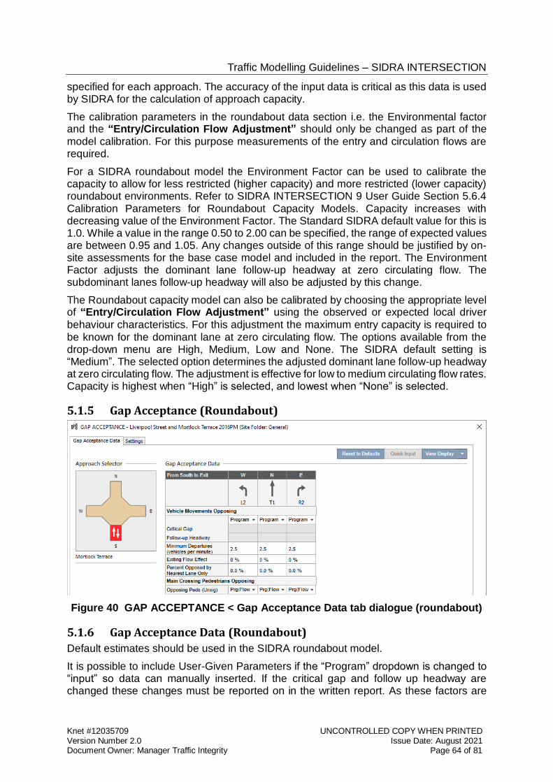
Traffic Modelling Guidelines – SIDRA INTERSECTION
Knet #12035709 UNCONTROLLED COPY WHEN PRINTED Version Number 2.0 Issue Date: August 2021 Document Owner: Manager Traffic Integrity Page 64 of 81
specified for each approach. The accuracy of the input data is critical as this data is used by SIDRA for the calculation of approach capacity.
The calibration parameters in the roundabout data section i.e. the Environmental factor and the “Entry/Circulation Flow Adjustment” should only be changed as part of the model calibration. For this purpose measurements of the entry and circulation flows are required.
For a SIDRA roundabout model the Environment Factor can be used to calibrate the capacity to allow for less restricted (higher capacity) and more restricted (lower capacity) roundabout environments. Refer to SIDRA INTERSECTION 9 User Guide Section 5.6.4 Calibration Parameters for Roundabout Capacity Models. Capacity increases with decreasing value of the Environment Factor. The Standard SIDRA default value for this is 1.0. While a value in the range 0.50 to 2.00 can be specified, the range of expected values are between 0.95 and 1.05. Any changes outside of this range should be justified by on-site assessments for the base case model and included in the report. The Environment Factor adjusts the dominant lane follow-up headway at zero circulating flow. The subdominant lanes follow-up headway will also be adjusted by this change.
The Roundabout capacity model can also be calibrated by choosing the appropriate level of “Entry/Circulation Flow Adjustment” using the observed or expected local driver behaviour characteristics. For this adjustment the maximum entry capacity is required to be known for the dominant lane at zero circulating flow. The options available from the drop-down menu are High, Medium, Low and None. The SIDRA default setting is “Medium”. The selected option determines the adjusted dominant lane follow-up headway at zero circulating flow. The adjustment is effective for low to medium circulating flow rates. Capacity is highest when “High” is selected, and lowest when “None” is selected.
5.1.5 Gap Acceptance (Roundabout)
Figure 40 GAP ACCEPTANCE < Gap Acceptance Data tab dialogue (roundabout)
5.1.6 Gap Acceptance Data (Roundabout)
Default estimates should be used in the SIDRA roundabout model.
It is possible to include User-Given Parameters if the “Program” dropdown is changed to “input” so data can manually inserted. If the critical gap and follow up headway are changed these changes must be reported on in the written report. As these factors are
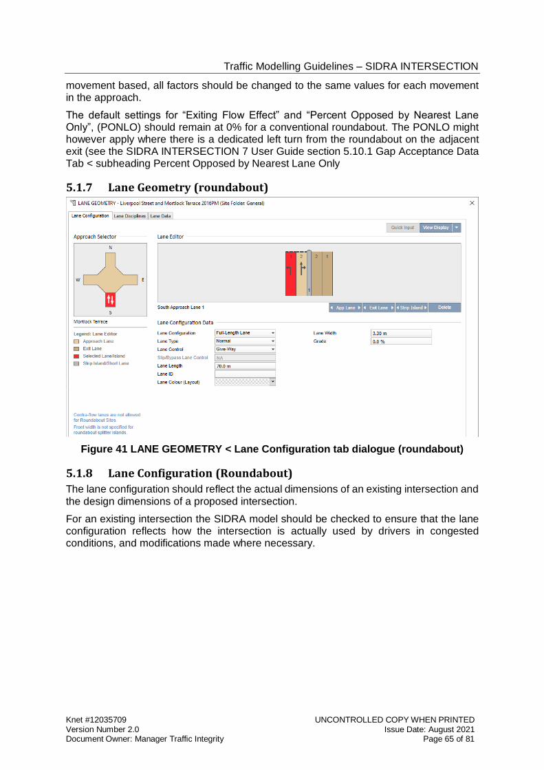
Traffic Modelling Guidelines – SIDRA INTERSECTION
Knet #12035709 UNCONTROLLED COPY WHEN PRINTED Version Number 2.0 Issue Date: August 2021 Document Owner: Manager Traffic Integrity Page 65 of 81
movement based, all factors should be changed to the same values for each movement in the approach.
The default settings for “Exiting Flow Effect” and “Percent Opposed by Nearest Lane Only”, (PONLO) should remain at 0% for a conventional roundabout. The PONLO might however apply where there is a dedicated left turn from the roundabout on the adjacent exit (see the SIDRA INTERSECTION 7 User Guide section 5.10.1 Gap Acceptance Data Tab < subheading Percent Opposed by Nearest Lane Only
5.1.7 Lane Geometry (roundabout)
Figure 41 LANE GEOMETRY < Lane Configuration tab dialogue (roundabout)
5.1.8 Lane Configuration (Roundabout)
The lane configuration should reflect the actual dimensions of an existing intersection and the design dimensions of a proposed intersection.
For an existing intersection the SIDRA model should be checked to ensure that the lane configuration reflects how the intersection is actually used by drivers in congested conditions, and modifications made where necessary.
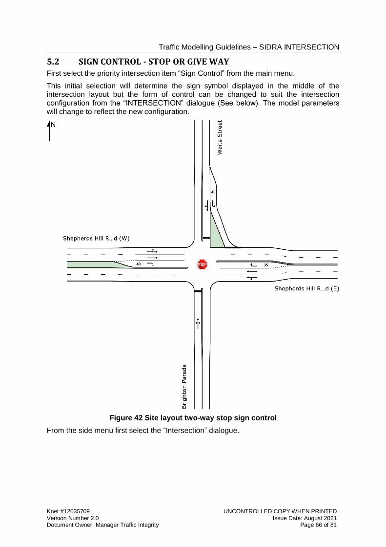
Traffic Modelling Guidelines – SIDRA INTERSECTION
Knet #12035709 UNCONTROLLED COPY WHEN PRINTED Version Number 2.0 Issue Date: August 2021 Document Owner: Manager Traffic Integrity Page 66 of 81
5.2 SIGN CONTROL - STOP OR GIVE WAY First select the priority intersection item “Sign Control” from the main menu.
This initial selection will determine the sign symbol displayed in the middle of the intersection layout but the form of control can be changed to suit the intersection configuration from the “INTERSECTION” dialogue (See below). The model parameters will change to reflect the new configuration.
Figure 42 Site layout two-way stop sign control
From the side menu first select the “Intersection” dialogue.
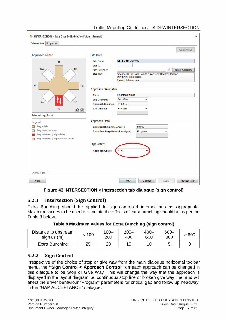
Traffic Modelling Guidelines – SIDRA INTERSECTION
Knet #12035709 UNCONTROLLED COPY WHEN PRINTED Version Number 2.0 Issue Date: August 2021 Document Owner: Manager Traffic Integrity Page 67 of 81
Figure 43 INTERSECTION < Intersection tab dialogue (sign control)
5.2.1 Intersection (Sign Control)
Extra Bunching should be applied to sign-controlled intersections as appropriate. Maximum values to be used to simulate the effects of extra bunching should be as per the Table 8 below.
Table 8 Maximum values for Extra Bunching (sign control)
Distance to upstream signals (m)
< 100 100–200
200–400
400–600
600–800
> 800
Extra Bunching 25 20 15 10 5 0
5.2.2 Sign Control
Irrespective of the choice of stop or give way from the main dialogue horizontal toolbar menu, the “Sign Control < Approach Control” on each approach can be changed in this dialogue to be Stop or Give Way. This will change the way that the approach is displayed in the layout diagram i.e. continuous stop line or broken give way line; and will affect the driver behaviour “Program” parameters for critical gap and follow up headway, in the “GAP ACCEPTANCE” dialogue.
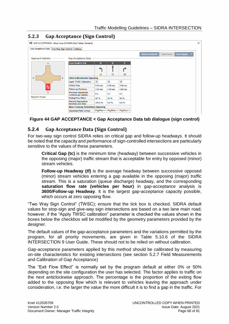
Traffic Modelling Guidelines – SIDRA INTERSECTION
Knet #12035709 UNCONTROLLED COPY WHEN PRINTED Version Number 2.0 Issue Date: August 2021 Document Owner: Manager Traffic Integrity Page 68 of 81
5.2.3 Gap Acceptance (Sign Control)
Figure 44 GAP ACCEPTANCE < Gap Acceptance Data tab dialogue (sign control)
5.2.4 Gap Acceptance Data (Sign Control)
For two-way sign control SIDRA relies on critical gap and follow-up headways. It should be noted that the capacity and performance of sign-controlled intersections are particularly sensitive to the values of these parameters.
Critical Gap (tc) is the minimum time (headway) between successive vehicles in the opposing (major) traffic stream that is acceptable for entry by opposed (minor) stream vehicles.
Follow-up Headway (tf) is the average headway between successive opposed (minor) stream vehicles entering a gap available in the opposing (major) traffic stream. This is a saturation (queue discharge) headway, and the corresponding saturation flow rate (vehicles per hour) in gap-acceptance analysis is 3600/Follow-up Headway. It is the largest gap-acceptance capacity possible, which occurs at zero opposing flow.
“Two Way Sign Control” (TWSC); ensure that the tick box is checked. SIDRA default values for stop-sign and give-way sign intersections are based on a two lane main road; however, if the “Apply TWSC calibration” parameter is checked the values shown in the boxes below the checkbox will be modified by the geometry parameters provided by the designer.
The default values of the gap-acceptance parameters and the variations permitted by the program, for all priority movements, are given in Table 5.10.6 of the SIDRA INTERSECTION 9 User Guide. These should not to be relied on without calibration.
Gap-acceptance parameters applied by this method should be calibrated by measuring on-site characteristics for existing intersections (see section 5.2.7 Field Measurements and Calibration of Gap Acceptance)
The “Exit Flow Effect” is normally set by the program default at either 0% or 50% depending on the site configuration the user has selected. The factor applies to traffic on the next anticlockwise approach. The percentage is the proportion of the exiting flow added to the opposing flow which is relevant to vehicles leaving the approach under consideration, i.e. the larger the value the more difficult it is to find a gap in the traffic. For
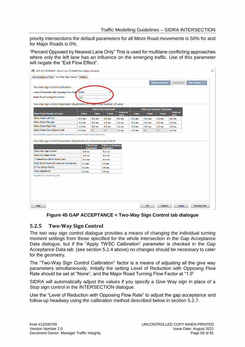
Traffic Modelling Guidelines – SIDRA INTERSECTION
Knet #12035709 UNCONTROLLED COPY WHEN PRINTED Version Number 2.0 Issue Date: August 2021 Document Owner: Manager Traffic Integrity Page 69 of 81
priority intersections the default parameters for all Minor Road movements is 50% for and for Major Roads is 0%.
“Percent Opposed by Nearest Lane Only” This is used for multilane conflicting approaches where only the left lane has an influence on the emerging traffic. Use of this parameter will negate the “Exit Flow Effect”.
Figure 45 GAP ACCEPTANCE < Two-Way Sign Control tab dialogue
5.2.5 Two-Way Sign Control
The two way sign control dialogue provides a means of changing the individual turning moment settings from those specified for the whole intersection in the Gap Acceptance Data dialogue, but if the “Apply TWSC Calibration” parameter is checked in the Gap Acceptance Data tab (see section 5.2.4 above) no changes should be necessary to cater for the geometry.
The “Two-Way Sign Control Calibration” factor is a means of adjusting all the give way parameters simultaneously. Initially the setting Level of Reduction with Opposing Flow Rate should be set at “None”, and the Major Road Turning Flow Factor at “1.0”
SIDRA will automatically adjust the values if you specify a Give Way sign in place of a Stop sign control in the INTERSECTION dialogue.
Use the “Level of Reduction with Opposing Flow Rate” to adjust the gap acceptance and follow-up headway using the calibration method described below in section 5.2.7.
Traffic Modelling Guidelines – SIDRA INTERSECTION
Knet #12035709 UNCONTROLLED COPY WHEN PRINTED Version Number 2.0 Issue Date: August 2021 Document Owner: Manager Traffic Integrity Page 70 of 81
5.2.6 Gap Acceptance Settings
The Gap Acceptance Capacity Model used by the Department is the SIDRA Standard (Akҫelik M3D).
Movement Class settings shall apply the Simple method, Figure 5.11.4 of the SIDRA 9 User Guide, to specify the Gap Acceptance Factor and Opposing Vehicle Factor parameter for large vehicles. The factor is based on a straight line relationship to the average queue space of heavy vehicles. Use the values calculated from Table 4 for Vehicle Length and Queue Space for determination of Gap Acceptance Factor and Opposing Vehicle Factor for each Movement Class.
5.2.7 Field Measurements and Calibration of Gap Acceptance
The capacity and performance results for gap acceptance cases at unsignalised intersections are very sensitive to the follow-up headway and critical gap parameters.
The field survey method comprises measuring departure flow rates during saturated (queued) portions of individual stop-go (gap-acceptance) cycles.
The survey method is implemented by:
Making observations during times when there is constant queuing in the minor street, say for 5 minutes.
Record the number of vehicles, n, entering each main stream gap (headway) of duration t.
For each of the gaps accepted by n vehicles compute the average of accepted gaps t.
Find the linear regression of the average gap headway values as a function of the number of vehicles.
From this, compute the “follow up headway” and “critical gap” using the formulae contained in the SIDRA INTERSECTION 9 User Guide, Section 5.10.5, Gap Acceptance Survey Method. Use the values obtained to modify where necessary the “base values” in SIDRA by using the “Level of Reduction with Opposing Flow Rate”.
The gap-acceptance method uses the follow-up headway (tf) as the queue discharge (saturation) headway. This is the maximum capacity that can be achieved when the opposing flow is close to zero. This corresponds to a saturation flow rate of “s” = 3600 / tf. For example, where tf = 2.5 seconds this implies a saturation flow of 1440 veh/h, where tf = 4.0 seconds means a maximum capacity of 900 veh/h whereas tf = 3.0 s means a maximum capacity of 1200 veh/h. The capacity is reduced from this value with increased opposing flow rates, due to decreased proportion of acceptable gaps.
As a useful rule of thumb, the Follow-up Headway will usually represent 60% of the Critical Gap.
After running the SIDRA model the calculated input values can be compared with the measured values and adjustments can be made by changing the “Level of Reduction with Opposing Flow Rate” (SIDRA INTERSECTION 9 User Guide section 5.10.2, Two-Way Sign Control Tab). The levels available are “None”, “Low”, “Medium” and “High”.
The survey date data shall be included in the report.
Traffic Modelling Guidelines – SIDRA INTERSECTION
Knet #12035709 UNCONTROLLED COPY WHEN PRINTED Version Number 2.0 Issue Date: August 2021 Document Owner: Manager Traffic Integrity Page 71 of 81
5.2.8 Staged Crossing – Special Parameter Settings
Staged road crossings might be experienced at priority controlled “Tee” intersections where the major road has a wide median and where it designed for vehicles to give way to traffic in the nearside carriageway and, after moving to the centre median, give way or merge in a separate movement.
Movements with similar characteristics can be experienced at intersections with a seagull traffic island.
The current version of SIDRA envisages the use of the “networking” capabilities to model this staged crossing. The Department does not currently approve models using the network feature of SIDRA. In previous versions of SIDRA, the Department has used a dummy movement to simulate this situation.
For staged crossings the designer shall scope a suitable model format for approval by the Department.
The designer shall ensure that the number of individual vehicles modelled can be physically accommodated (stored) in the central median by checking the predicted queue lengths against the storage available.
If wide cross intersections, with give way or stop signs, are to be modelled the behaviour of right turn drivers in the median needs additional consideration.
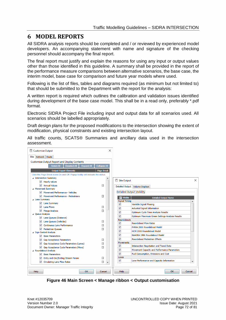
Traffic Modelling Guidelines – SIDRA INTERSECTION
Knet #12035709 UNCONTROLLED COPY WHEN PRINTED Version Number 2.0 Issue Date: August 2021 Document Owner: Manager Traffic Integrity Page 72 of 81
6 MODEL REPORTS All SIDRA analysis reports should be completed and / or reviewed by experienced model developers. An accompanying statement with name and signature of the checking personnel should accompany the final report.
The final report must justify and explain the reasons for using any input or output values other than those identified in this guideline. A summary shall be provided in the report of the performance measure comparisons between alternative scenarios, the base case, the interim model, base case for comparison and future year models where used.
Following is the list of files, tables and diagrams required (as minimum but not limited to) that should be submitted to the Department with the report for the analysis:
A written report is required which outlines the calibration and validation issues identified during development of the base case model. This shall be in a read only, preferably *.pdf format.
Electronic SIDRA Project File including input and output data for all scenarios used. All scenarios should be labelled appropriately.
Draft design plans for the proposed modifications to the intersection showing the extent of modification, physical constraints and existing intersection layout.
All traffic counts, SCATS® Summaries and ancillary data used in the intersection assessment.
Figure 46 Main Screen < Manage ribbon < Output customisation
Traffic Modelling Guidelines – SIDRA INTERSECTION
Knet #12035709 UNCONTROLLED COPY WHEN PRINTED Version Number 2.0 Issue Date: August 2021 Document Owner: Manager Traffic Integrity Page 73 of 81
SIDRA produces a variety of outputs to assist in compiling the written report. These outputs are selectable from the Manage ribbon.
Extracts of these outputs may be used in the Model report and in the Traffic Signals Operation Performance Report (TSOPR).
The written report may use part of the output to illustrate project issues but should not comprise copious amounts of irrelevant output.
A Traffic Signals Operation Performance Report is required for traffic signal projects as a requirement of the RD-EL-D2 Traffic Signals Design Master Specification. The TSOPR should reflect the logical approach taken by a designer to resolve the complex and iterative nature of traffic modelling. It should emphasise the sound engineering principles adopted during model development. Without accurate reporting the model development process is hindered by a lack of historical information. The following subsections outline an approach to model reporting which should allow a third party to accurately comprehend the decisions made during the development process from intersection site familiarisation through to scenario evaluation.
A traffic model may be developed over a long period by a number of different designers. While developing a model the designer/s should retain detailed notes that include a record of all assumptions and modelling decisions. These notes should be kept for future reference, and can form the basis for subsequent reporting in the Traffic Signals Operation Performance Report.
It is the responsibility of the designer and the project manager to ensure that all reporting is accurate, thorough and sufficient, and that submitted documents are fit for purpose to adequately support accompanying models. The SIDRA data files for each intersection included in the report must accompany the Traffic Signals Operation Performance Reports submitted to the Department.
6.1 Calibration Report The calibration section of the Traffic Signals Operation Performance Report should present all relevant survey data and include a history of model development.
Model auditing will rely on the Traffic Signals Operation Performance Report to explain how the model has been calibrated. For this reason the calibration section of the Traffic Signals Operation Performance Report should focus on presenting traffic model inputs and detailing how the model has been developed to ensure that it represents existing conditions. In particular, the following should be included:
The stated purpose of the model;
A list of all SCATS® site numbers related to the model/s, with street addresses, and where required, a note detailing any operational relationships with adjacent major intersections.
Clear notes on any site observations and measurements, covering both the physical attributes and observed vehicle behaviour. Where behaviour is specific to a particular time of day, this should be noted along with how it has been accounted for in the model/s;
A table of adjusted saturation flows for each lane of the intersection and the relative measured saturation flows,
The effective bay lengths and flare lengths
Traffic Modelling Guidelines – SIDRA INTERSECTION
Knet #12035709 UNCONTROLLED COPY WHEN PRINTED Version Number 2.0 Issue Date: August 2021 Document Owner: Manager Traffic Integrity Page 74 of 81
The lane utilisation used in the model compared to measured queues or volumes.
6.2 Validation Report Validation Traffic Signals Operation Performance Reports should look in detail at comparisons between calibrated model results and existing conditions. The designer should detail the validation process, from on-site surveys through to adjustments made within the model. Any decisions made by the designer should be captured in the report especially where model inputs have been adjusted in order to achieve validation.
Validated model results should be tabulated and compared with the surveyed on-street values for all modelled periods. If there are discrepancies between the model outputs and the on-street conditions then these should be identified, investigated and explained. Specific items that could be included in the validation section of the Traffic Signals Operation Performance Report are:
Details of traffic flows used, where and when they were sourced from and how the model periods were chosen;
Minimum Phase time adjustments made to reflect average phase utilisation e.g. where pedestrian phases are demand dependent;
Validation data, such as DoS and vehicle journey times;
Relevant site observations not already included in the calibration section of the Traffic Signals Operation Performance Report , such as:
Give-way behaviour, exit-blocking, flare/non-green usage, parking/loading and bottleneck details; and
Evidence of validation, comparing modelled results to on-street observations and measurements.
Any discrepancies between observed and model outputs should be analysed and discussed.
6.3 Scenario Models Report The Traffic Signals Operation Performance Report accompanying any scenario model must give a full description of the scenario and any expected model impacts (e.g. any expected changes in demand i.e. the project specification requirement for projected flows). The modifications made to the validated base case model to develop the scenario model should all be based on these key details. All changes made in order to develop the scenario model should be documented by the designer, along with the reasoning behind them. Specific items that should therefore be included in the scenario section of the Traffic Signals Operation Performance Report are:
Project summary
Project objectives/problem identification
Scenario traffic management strategy
Evaluation of scenario results compared to the base case for comparison including vehicle delays and level of service.
Conclusions and recommendations
Design summary sheets
Traffic Modelling Guidelines – SIDRA INTERSECTION
Knet #12035709 UNCONTROLLED COPY WHEN PRINTED Version Number 2.0 Issue Date: August 2021 Document Owner: Manager Traffic Integrity Page 75 of 81
Model source data
Modelling assumptions - (including workaround’s required because of model limitations)
Electronic copies of model data file/s, (which include input and output data), must be supplied with the text report
The Scenario report must also provide details of the performance of each intersection using the specified design traffic flows including:
Degree of saturation, LOS and predicted queue lengths for individual traffic lanes
Intersection layout plans, traffic signal phasing, phase sequences and time settings
Discussion of alternative schemes considered and reasons for the recommendations
History of design changes with supporting reasons from 30% Nominal Design through to the Final Design
Discussion of any variations from the requirements of the original project specification
Results of the scenario model should be compared to the validated base case model/s. This should be done for all modelled periods to demonstrate the impact of the scenarios. The scenario section of the Traffic Signals Operation Performance Report should include a discussion of results. It is useful to include a section detailing the impact of any geometric changes as this enables informed decisions about preferred design options. Version control should be applied to all model design documents to avoid ambiguity thus ensuring all parties are aware of the current design status for each scenario model.
All data presented with the validated and approved base case models should be presented in conjunction with the scenario section as the Department will use the modelling output and analysis to make an assessment of the likely impacts of the project and in determining the traffic signals personality conditions to be programmed. Data provided with the base case and scenario model submissions will be considered when producing the personality, therefore it is in the designers’ interest to ensure scenario model reports are provided with adequate detail.
6.4 Recommended Scenario It is essential that the designer include in the scenario section of the Traffic Signals Operation Performance Report a clear description of the recommended Scenario for the project.
SIDRA uses vehicle delays as the principle method of comparing alternative project options, and this shall be used to compare the base case with the project scenarios and to select the recommended scenario. The designer may however base the selection using additional criteria and this needs to be included in the report.
The designer needs to be cautious that the preferred option does not include excessive queues [e.g. on side roads], not apparent in comparing overall performance.
Traffic Modelling Guidelines – SIDRA INTERSECTION
Knet #12035709 UNCONTROLLED COPY WHEN PRINTED Version Number 2.0 Issue Date: August 2021 Document Owner: Manager Traffic Integrity Page 76 of 81
7 APPENDIX A - MODEL SCOPING DOCUMENT Document clearly in a “model scoping document” the reason for and purpose of the model e.g. to consider the impact of a major project or a new development, and all the model requirements.
Where the model/s is being prepared for a discrete project the project specification should adequately describe the modelling requirements. The designer shall however prepare and submit to the Department a “model scoping document” in order to confirm the modelling requirements at the commencement of modelling.
In preparing the model scoping document the designer should describe the objectives in a clear series of expected outputs for example:
Use the model to recommend any phase sequence and or infrastructure changes that would improve transport / travel conditions.
List all the sites to be included in the model/s and provide a map to illustrate the model scope showing symbolically the location of the intersections.
List the model options to be created; which shall always include a base case and at least one project case scenario. The project case scenarios shall be compared with the “base case for comparison”.
List the scenario options which may include various changes to the phase sequence/s, geometry, lane configuration and cycle length.
Input Objectives:
o Collect input data; Use SCATS® summaries for all control data.
o List the traffic demand periods to be modelled e.g. AM and PM peaks and representative development site peak hour. The models shall represent hourly traffic volumes.
o Calibrate base case models based on AM and PM peak traffic operations. Calibration is intended to check all model input parameters are correct.
o Validate base case models of existing traffic conditions for AM, PM and any other model periods required to be modelled.
Comparison of Degree of Saturation output with expected values shall be the main parameter used for validating the model.
Optimise signal timings for the scenario models for the same periods of the day as the base case models.
The scenario options shall not be modelled until the base case model is calibrated and validated to the satisfaction of the project manager and the Department.
Models of new scenarios are to reflect alternative phasing, recent traffic signal changes and geometric changes to the road.
The Base Case for Comparison model shall be a fair representation of the traffic conditions prevailing at the start of the project construction / installation.
The traffic modelling tool selected for this project is the latest version of SIDRA. The SIDRA version number should be provided in the modelling scope statement.
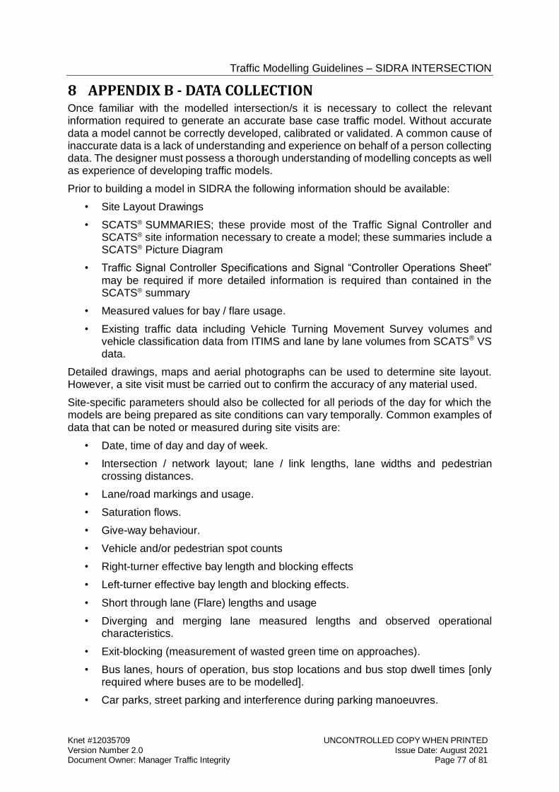
Traffic Modelling Guidelines – SIDRA INTERSECTION
Knet #12035709 UNCONTROLLED COPY WHEN PRINTED Version Number 2.0 Issue Date: August 2021 Document Owner: Manager Traffic Integrity Page 77 of 81
8 APPENDIX B - DATA COLLECTION Once familiar with the modelled intersection/s it is necessary to collect the relevant information required to generate an accurate base case traffic model. Without accurate data a model cannot be correctly developed, calibrated or validated. A common cause of inaccurate data is a lack of understanding and experience on behalf of a person collecting data. The designer must possess a thorough understanding of modelling concepts as well as experience of developing traffic models.
Prior to building a model in SIDRA the following information should be available:
• Site Layout Drawings
• SCATS® SUMMARIES; these provide most of the Traffic Signal Controller and SCATS® site information necessary to create a model; these summaries include a SCATS® Picture Diagram
• Traffic Signal Controller Specifications and Signal “Controller Operations Sheet” may be required if more detailed information is required than contained in the SCATS® summary
• Measured values for bay / flare usage.
• Existing traffic data including Vehicle Turning Movement Survey volumes and vehicle classification data from ITIMS and lane by lane volumes from SCATS® VS data.
Detailed drawings, maps and aerial photographs can be used to determine site layout. However, a site visit must be carried out to confirm the accuracy of any material used.
Site-specific parameters should also be collected for all periods of the day for which the models are being prepared as site conditions can vary temporally. Common examples of data that can be noted or measured during site visits are:
• Date, time of day and day of week.
• Intersection / network layout; lane / link lengths, lane widths and pedestrian crossing distances.
• Lane/road markings and usage.
• Saturation flows.
• Give-way behaviour.
• Vehicle and/or pedestrian spot counts
• Right-turner effective bay length and blocking effects
• Left-turner effective bay length and blocking effects.
• Short through lane (Flare) lengths and usage
• Diverging and merging lane measured lengths and observed operational characteristics.
• Exit-blocking (measurement of wasted green time on approaches).
• Bus lanes, hours of operation, bus stop locations and bus stop dwell times [only required where buses are to be modelled].
• Car parks, street parking and interference during parking manoeuvres.
Traffic Modelling Guidelines – SIDRA INTERSECTION
Knet #12035709 UNCONTROLLED COPY WHEN PRINTED Version Number 2.0 Issue Date: August 2021 Document Owner: Manager Traffic Integrity Page 78 of 81
• Restrictions on the approaches (parking/stopping/loading, etc.).
• Speed limits.
• Roadworks and other incidents, and their impact on throughput.
• Degree of saturation (it is important to know which approaches are oversaturated for each modelling period, this is used in validating the models).
• Queue lengths.
Whilst many of these parameters can be measured in quantifiable terms, it is also important to record general site observations that capture more subtle behaviour exhibited within the study area. It can be useful to note where traffic behaviour does not reflect street markings or the intended geometric design of an intersection, for example where ahead moving vehicles use a dedicated left-turn lane.
Many parameters are time dependent, and should therefore be recorded for each period being modelled, such as effective bay usage which can vary at a site according to differing traffic patterns.
8.1 Traffic Count Data The project specification will detail the traffic flow requirements for model assessment. It is however essential, that recent and relevant traffic volumes are used to assess existing traffic networks, for validation purposes.
The selection of suitable model data is the responsibility of the designer, and the model process should allow for the survey of additional data to fill any gaps in the data available from previous surveys.
It is the designer’s responsibility to ensure that the Traffic counts and green splits are supplied for the same relative periods at all modelled intersections, i.e. that they are compatible for calibration and validation of the models, and representative and appropriate for the project assessment being undertaken.
Vehicle Turning Movement Survey volumes and classified counts may be obtained on request from the “Integrated Transport Intelligence and Mapping System” (ITIMS) Traffic Information Map website maintained by the Transport Analytics Directorate. This information may be requested from the address [email protected].
An example of the Vehicle Turning Movement Survey pdf format report is shown below:
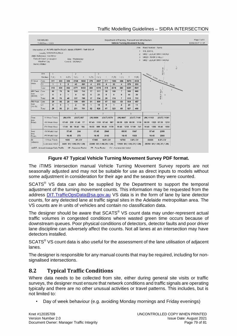
Traffic Modelling Guidelines – SIDRA INTERSECTION
Knet #12035709 UNCONTROLLED COPY WHEN PRINTED Version Number 2.0 Issue Date: August 2021 Document Owner: Manager Traffic Integrity Page 79 of 81
Figure 47 Typical Vehicle Turning Movement Survey PDF format.
The iTIMS intersection manual Vehicle Turning Movement Survey reports are not seasonally adjusted and may not be suitable for use as direct inputs to models without some adjustment in consideration for their age and the season they were counted.
SCATS® VS data can also be supplied by the Department to support the temporal adjustment of the turning movement counts. This information may be requested from the address [email protected] VS data is in the form of lane by lane detector counts, for any detected lane at traffic signal sites in the Adelaide metropolitan area. The VS counts are in units of vehicles and contain no classification data.
The designer should be aware that SCATS® VS count data may under-represent actual traffic volumes in congested conditions where wasted green time occurs because of downstream queues. Poor physical conditions of detectors, detector faults and poor driver lane discipline can adversely affect the counts. Not all lanes at an intersection may have detectors installed.
SCATS® VS count data is also useful for the assessment of the lane utilisation of adjacent lanes.
The designer is responsible for any manual counts that may be required, including for non-signalised intersections.
8.2 Typical Traffic Conditions Where data needs to be collected from site, either during general site visits or traffic surveys, the designer must ensure that network conditions and traffic signals are operating typically and there are no other unusual activities or travel patterns. This includes, but is not limited to:
• Day of week behaviour (e.g. avoiding Monday mornings and Friday evenings)
Traffic Modelling Guidelines – SIDRA INTERSECTION
Knet #12035709 UNCONTROLLED COPY WHEN PRINTED Version Number 2.0 Issue Date: August 2021 Document Owner: Manager Traffic Integrity Page 80 of 81
• School holidays
• Roadworks
• Temporary road closures
• Events
• Festivals
• Traffic incidents
• Temporary loss of SCATS® Masterlink control (e.g. local control), and
• Temporary use of atypical (e.g. SCATS® fall back) timing plans and strategies
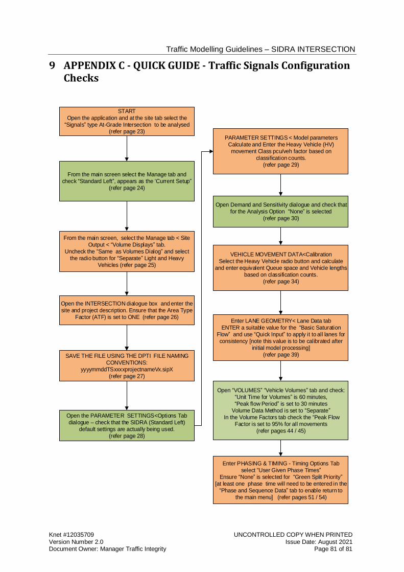
Traffic Modelling Guidelines – SIDRA INTERSECTION
Knet #12035709 UNCONTROLLED COPY WHEN PRINTED Version Number 2.0 Issue Date: August 2021 Document Owner: Manager Traffic Integrity Page 81 of 81
9 APPENDIX C - QUICK GUIDE - Traffic Signals Configuration Checks
STARTOpen the application and at the site tab select the
Signals type At-Grade Intersection to be analysed (refer page 23)
From the main screen select the Manage tab and check Standard Left , appears as the Current Setup
(refer page 24)
Open the INTERSECTION dialogue box and enter the site and project description. Ensure that the Area Type
Factor (ATF) is set to ONE (refer page 26)
SAVE THE FILE USING THE DPTI FILE NAMING CONVENTIONS:
yyyymmddTSxxxxprojectnameVx.sipX(refer page 27)
Open the PARAMETER SETTINGS<Options Tab dialogue – check that the SIDRA (Standard Left)
default settings are actually being used. (refer page 28)
Open Demand and Sensitivity dialogue and check that for the Analysis Option None is selected
(refer page 30)
Enter LANE GEOMETRY< Lane Data tabENTER a suitable value for the Basic Saturation
Flow and use Quick Input to apply it to all lanes for consistency [note this value is to be calibrated after
initial model processing](refer page 39)
Open VOLUMES Vehicle Volumes tab and check: Unit Time for Volumes is 60 minutes, Peak flow Period is set to 30 minutes
Volume Data Method is set to Separate In the Volume Factors tab check the Peak Flow
Factor is set to 95% for all movements(refer pages 44 / 45)
Enter PHASING & TIMING - Timing Options Tab select User Given Phase Times
Ensure None is selected for Green Split Priority [at least one phase time will need to be entered in the
Phase and Sequence Data tab to enable return to the main menu] (refer pages 51 / 54)
From the main screen, select the Manage tab < Site Output < Volume Displays tab.
Uncheck the Same as Volumes Dialog and select the radio button for Separate Light and Heavy
Vehicles (refer page 25)
PARAMETER SETTINGS < Model parametersCalculate and Enter the Heavy Vehicle (HV) movement Class pcu/veh factor based on
classification counts.(refer page 29)
VEHICLE MOVEMENT DATA<CalibrationSelect the Heavy Vehicle radio button and calculate
and enter equivalent Queue space and Vehicle lengths based on classification counts.
(refer page 34)
Traffic Modelling Guidelines – SIDRA INTERSECTION
Knet #12035709 UNCONTROLLED COPY WHEN PRINTED Version Number 2.0 Issue Date: August 2021 Document Owner: Manager Traffic Integrity Page 82 of 81
10 APPENDIX D – SUPPORT SERVICES
10.1 SCATS® summaries
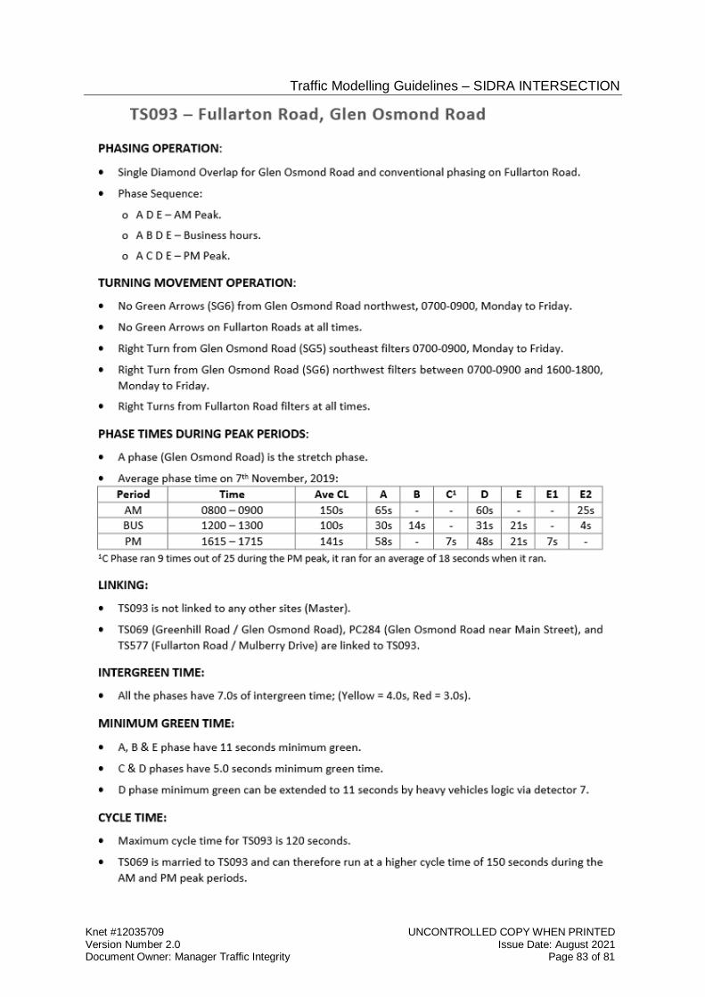
Traffic Modelling Guidelines – SIDRA INTERSECTION
Knet #12035709 UNCONTROLLED COPY WHEN PRINTED Version Number 2.0 Issue Date: August 2021 Document Owner: Manager Traffic Integrity Page 83 of 81
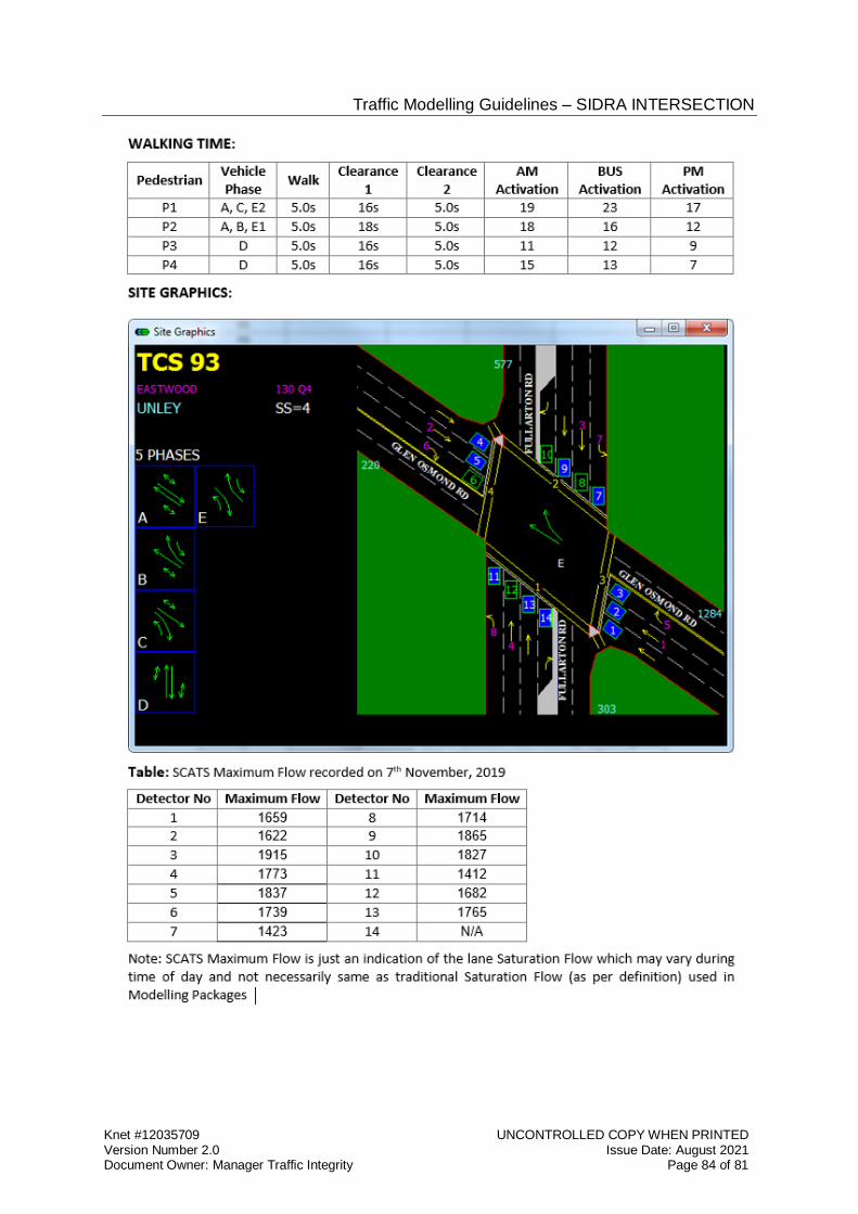
Traffic Modelling Guidelines – SIDRA INTERSECTION
Knet #12035709 UNCONTROLLED COPY WHEN PRINTED Version Number 2.0 Issue Date: August 2021 Document Owner: Manager Traffic Integrity Page 84 of 81
Traffic Modelling Guidelines – SIDRA INTERSECTION
Knet #12035709 UNCONTROLLED COPY WHEN PRINTED Version Number 2.0 Issue Date: August 2021 Document Owner: Manager Traffic Integrity Page 85 of 81
11 APPENDIX E - SOURCE MATERIAL Akcelik, R. (1981) traffic signals: Capacity and Timing Analysis. Research Report, ARR_123, ARRB Transport Research Ltd, Vermont South, Australia (6TH reprint 1995).
Akcelik & Associates Pty Ltd (2010), SIDRA INTERSECTION 9 User Guide, October 2020.
AUSTROADS – AGTM02 Guide to Traffic Management Part 2: Traffic Theory. Association of Australian State Road and Transport Authorities, Sydney.
AUSTROADS – AGTM03 Guide to Traffic Management Part 3: Traffic Studies and Analysis. Association of Australian State Road and Transport Authorities, Sydney.
AUSTROADS – AGTM10 Guide to Traffic Management Part 9: Traffic Operations Association of Australian State Road and Transport Authorities, Sydney.
AUSTROADS – AGRD04A Road Design Guide Part 4A: Unsignalised and Signalised Intersections. Association of Australian State Road and Transport Authorities, Sydney.
National Heavy Vehicle Register, National Transport Commission – Performance – Based Standards Scheme – Network Classification Guidelines July 2007. https://www.nhvr.gov.au/files/resources/0018-pbsnetwrkclassglines.pdf
National Transport Commission (NTC) Third Heavy Vehicle Road Pricing Determination: Technical Report – Appendix B Table 47, October 2005, Melbourne, Australia. https://www.ntc.gov.au/Media/Reports/ (A1663BA1-4E58-AF24-EA11-7339D2553F63).pdf
National Transport Commission - Heavy vehicle charges Report to the Standing Council of Transport and Infrastructure February 2012. http://www.ntc.gov.au/Media/Reports/(25A93AE3-86FB-FCE2-9D20-648467189BE3).pdf
Roads and Traffic Authority NSW (2002), Guide to Traffic Generating Developments version 2.2 October 2002. http://www.rms.nsw.gov.au/documents/projects/guide-to-generating-traffic-developments.pdf
Transport for London Traffic Modelling Guidelines v3. https://tfl.gov.uk/cdn/static/cms/documents/tfl-traffic-modelling-guidelines.pdf
Transport for London Modelling Audit Process. https://tfl.gov.uk/cdn/static/cms/documents/tfl-traffic-directorate-map-design-engineer-guide-v3.0.pdf
Transport for New South Wales, Roads and Maritime Services - Technical Direction TDT2013/04a - Guide to Traffic Generating Developments - Updated traffic surveys – August 2013. Guide to Traffic Generating Developments. Updated traffic surveys. (nsw.gov.au)
TRB (2016), - Highway Capacity Manual, Transport Research Board, National Research Council Washington D.C., U.S.A. [“HCM 6”].
Mainroads Western Australia – Operational Modelling Guidelines Version 2.0, 20 January 2021. Mainroads Western Australia, Technical Library, Operational Modelling
Mainroads Western Australia - Auditing Process for Operational Modelling version 2.0, 30 October 2020.
Traffic Modelling Guidelines – SIDRA INTERSECTION
Knet #12035709 UNCONTROLLED COPY WHEN PRINTED Version Number 2.0 Issue Date: August 2021 Document Owner: Manager Traffic Integrity Page 86 of 81
Transport for New South Wales, Roads and Maritime Services – Traffic Modelling Guidelines version 1.0 February 2013. Traffic Modelling Guidelines (nsw.gov.au)
Transport for New South Wales, Roads and Maritime Services – RTA Guide to Traffic Generating Developments. Issue 2.2 October 2002. Guide to Traffic Generating Developments version 2.2 (nsw.gov.au)
Department of Transport, VicRoads Transport Modelling Guidelines Volume 5: Intersection Modelling Draft 29 June 2020. https://www.vicroads.vic.gov.au/-/media/files/technical-documents-new/miscellaneous-guidelines/transport-modelling-guidelines-volume-5-intersection-modelling-june-2020.ashx?la=en&hash=5715F2AC45C5B8422EAD7CA4D973790D


