24
Traffic Steering in LTE – Wi-Fi Converged RANs Thomas V Pasca, Anil Kumar R, Bheemarjuna Reddy Tamma, Antony Franklin and Kiran Kuchi IIT Hyderabad 1

Traffic Steering in LTE – Wi-Fi Converged RANs
Thomas V Pasca, Anil Kumar R, Bheemarjuna Reddy Tamma, Antony Franklin and
Kiran Kuchi
IIT Hyderabad
1
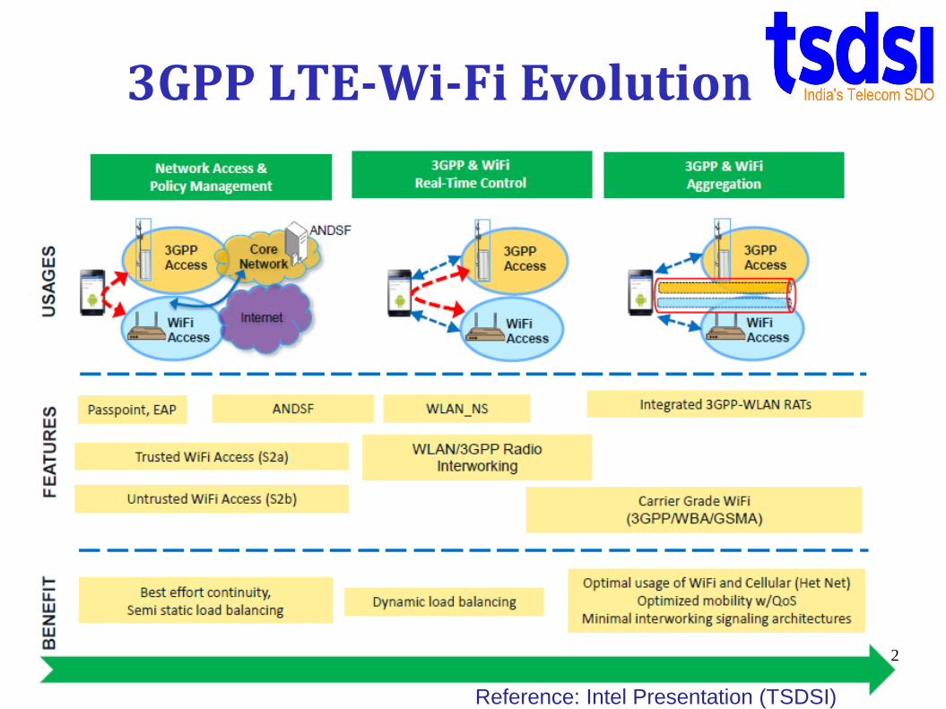
3GPP LTE-Wi-Fi Evolution
2
Reference: Intel Presentation (TSDSI)

3GPP current status on LTE/Wi-Fi interworking
3
Reference: Intel Presentation (TSDSI)

Converged RAN (C-RAN) Architecture
4
Reference: Intel Presentation (TSDSI)Intel’s proposal to 3GPP
Benefits of C-RAN
• Additional radio resources• Simplified network
architecture• Unified OAM and security• Mobility anchored at LTE• Reduced control signaling• Tightly coupled radio bearer• Improved traffic steering• Better QoS
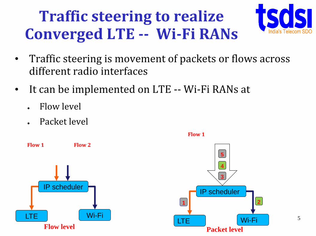
Traffic steering to realize Converged LTE -- Wi-Fi RANs
• Traffic steering is movement of packets or flows across different radio interfaces
• It can be implemented on LTE -- Wi-Fi RANs at
● Flow level
● Packet levelFlow 1
Flow 1 Flow 2
5
IP scheduler
LTE Wi-Fi
Flow level
IP scheduler
LTE Wi-Fi
3
4
5
1 2
Packet level
6
IP scheduler
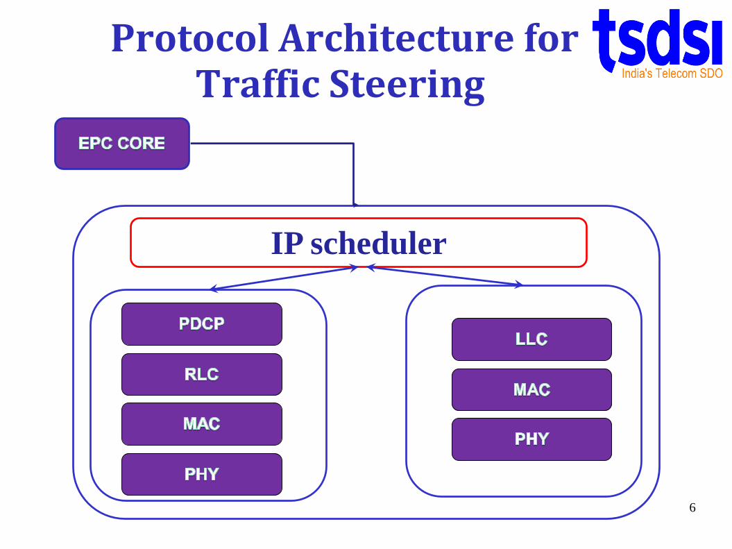
Protocol Architecture for Traffic Steering

Traffic Steering
Decision parameters
● Current traffic load
● Measurement reports from UE
● Current user plane throughput
● User plane latency
● TCP error rates
● EPS bearer (QoS parameters)
● etc 7
Traffic steering mechanism can rely on various parameters to decide which of LTE or Wi-Fi radio interface to forward next packet/flow to

Traffic Steering
• Co-ordination between UE and eNB is conveyed through RRC Signaling
• Only static traffic steering mechanisms at flow level are discussed in next slides
Objectives
• No changes in protocol stack and hardware at UE side
• Simple solution for faster deployment
8

Naïve Traffic Steering Mechanisms
• Naïve per flow traffic steering
– IP flow mobility
– Transmit equal number of flows through LTE and Wi-Fi radios
• Naïve per packet traffic steering
– Extension of IP flow mobility
– Transmit packets (without checking their flow level info) alternatively through LTE and Wi-Fi radios
9

Efficient Per flow Traffic Steering Mechanisms
• LTE for UL flows and Wi-Fi for DL flows
– Extension of IP flow mobility in LTE-TDD
– All uplink flows are sent through LTE (faster and no contention)
– All downlink flows are sent through Wi-Fi (no contention in DL, if no other WLAN AP is operating on the same channel)
• LTE (UL[App. Data & App. Control ] + DL [ App. Control]) and Wi-Fi DL App. Data
– All uplink flows (TCP Data and TCP ACK) are sent through LTE and all downlink TCP ACK flows are sent through LTE DL as Wi-Fi introduces more delay to ACK packets in DL
– Only downlink TCP Data flows are sent through Wi-Fi10

Per flow Traffic Steering Mechanisms
11
EPC CORE
LTE
Wi
Fi
LTE
Wi
Fi
1. ONLY LTE
2. ONLY Wi-Fi
3. LTE + Wi-Fi (pkt-
level/flow-level at IP)
INTEGRATED BOX
USER
EQUIPMENT
REMOTEHOST

Per flow Traffic Steering Mechanisms
12
EPC CORE
LTE
Wi
Fi
LTE
Wi
Fi
4. LTE UL & Wi-Fi DL
INTEGRATED BOX
USER
EQUIPMENT
REMOTEHOST
App. Data + App. Control
App. Data + App. Control

Per flow Traffic Steering Mechanisms
13
EPC CORE
LTE
Wi
Fi
LTE
Wi
Fi
5. LTE UL( App. Data +
App. Control) and
LTE DL (App. Control)
+ Wi-Fi DL (App. Data)
INTEGRATED BOX
USER
EQUIPMENT
REMOTEHOST
App. Data
App. Data + App. Control
App. Control
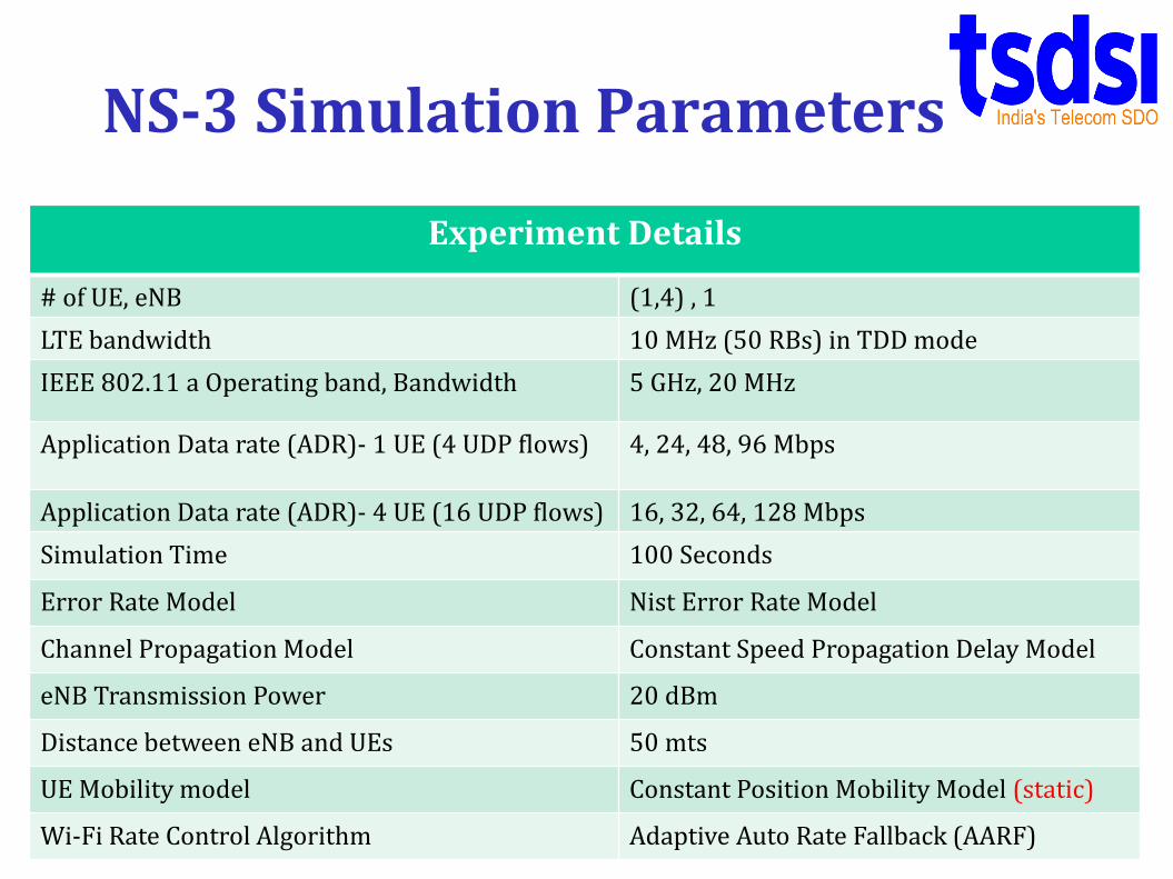
NS-3 Simulation Parameters
14
Experiment Details
# of UE, eNB (1,4) , 1
LTE bandwidth 10 MHz (50 RBs) in TDD mode
IEEE 802.11 a Operating band, Bandwidth 5 GHz, 20 MHz
Application Data rate (ADR)- 1 UE (4 UDP flows) 4, 24, 48, 96 Mbps
Application Data rate (ADR)- 4 UE (16 UDP flows) 16, 32, 64, 128 Mbps
Simulation Time 100 Seconds
Error Rate Model Nist Error Rate Model
Channel Propagation Model Constant Speed Propagation Delay Model
eNB Transmission Power 20 dBm
Distance between eNB and UEs 50 mts
UE Mobility model Constant Position Mobility Model (static)
Wi-Fi Rate Control Algorithm Adaptive Auto Rate Fallback (AARF)

Experimental Scenarios
• Scenario 1: 1 UE (4 flows) in a single cell
– 2 Uplink flows and 2 Downlink flows for each UE
– TCP expt: 4 Large file txs till the end of simulation
– UDP expt: Each flow is configured with (1, 6, 12, 24 Mbps) application data rate. So, the network load will be (4, 24, 64, 96 Mbps)
• Scenario 2: 4 UEs (16 flows) in a single cell
– 2 Uplink flows and 2 Downlink flows for each UE
– TCP expt: 16 Large file txs till the end of simulation
– UDP expt: Each flow is configured with (1, 2, 4, 8 Mbps) application data rate. So, the network load will be (16, 32, 64, 128 Mbps) 15
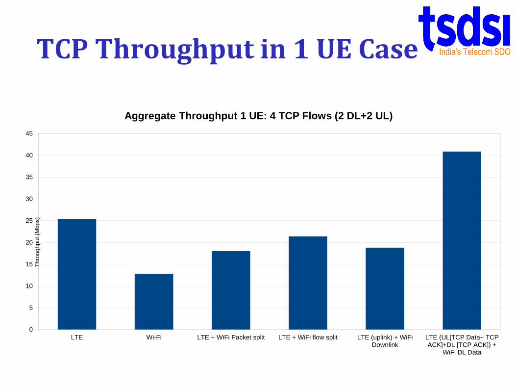
TCP Throughput in 1 UE Case
16
0
5
10
15
20
25
30
35
40
45
LTE Wi-Fi LTE + WiFi Packet split LTE + WiFi flow split LTE (uplink) + WiFiDownlink
LTE (UL[TCP Data+ TCPACK]+DL [TCP ACK]) +
WiFi DL Data
Th
rou
gh
pu
t (M
bp
s)
Aggregate Throughput 1 UE: 4 TCP Flows (2 DL+2 UL)
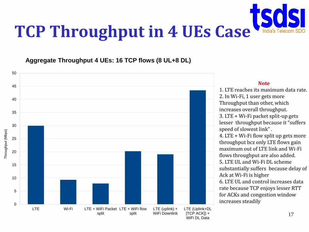
TCP Throughput in 4 UEs Case
17
0
5
10
15
20
25
30
35
40
45
50
LTE Wi-Fi LTE + WiFi Packetsplit
LTE + WiFi flowsplit
LTE (uplink) +WiFi Downlink
LTE (Uplink+DL[TCP ACK]) +WiFi DL Data
Th
rou
gh
pu
t (M
bp
s)
Aggregate Throughput 4 UEs: 16 TCP flows (8 UL+8 DL)
Note1. LTE reaches its maximum data rate.2. In Wi-Fi, 1 user gets more Throughput than other, which increases overall throughput.3. LTE + Wi-Fi packet split-up gets lesser throughput because it “suffers speed of slowest link” .4. LTE + Wi-Fi flow split up gets more throughput bcz only LTE flows gain maximum out of LTE link and Wi-Fi flows throughput are also added.5. LTE UL and Wi-Fi DL scheme substantially suffers because delay of Ack at Wi-Fi is higher6. LTE UL and control increases data rate because TCP enjoys lesser RTT for ACKs and congestion window increases steadily

0
10
20
30
40
50
60
70
4 24 48 96
Th
rou
gh
pu
t (M
bp
s)
Application data rate (Mbps)
Agg. Throughput 1 UE: 4 UDP flows (2DL+2UL)LTE
Wi-Fi
LTE + WiFi
LTE Uplink WiFi Downlink
Note1. UDP throughput harvest theMaximum capacity of the links.
2.LTE + Wi-Fi has sum of radio capacity of LTE and Wi-Fi.
3.LTE – UL and Wi-Fi DL has the highest capacity becausecontention for the channelbetween UE and eNB (Wi-Fi)is avoided.
18
TCP Throughput in 1 UE Case

0
10
20
30
40
50
60
16 32 64 128
Th
rou
gh
pu
t (M
bp
s)
Application DataRate (Mbps)
Agg. UDP throughput 4 UEs: 16 UDP flows (8UL+8DL)
LTE
Wi-Fi
LTE + WiFi
LTE Uplink WiFi Downlink
Note1. Wi-Fi throughput has
reduced tremendously because of contention.
2. LTE + Wi-Fi has the effect of Wi-Fi contention but LTE-UL and Wi-Fi - DL avoids contention.
3. LTE – UL and Wi-Fi DL needs LTE- TDD.
19
TCP Throughput in 4 UEs Case
0
0.05
0.1
0.15
0.2
0.25
0.3
0.35
4 24 48 96
Ave
rag
e D
ela
y f
or
4 f
low
s (
Se
c)
Application Datarate (Mbps)
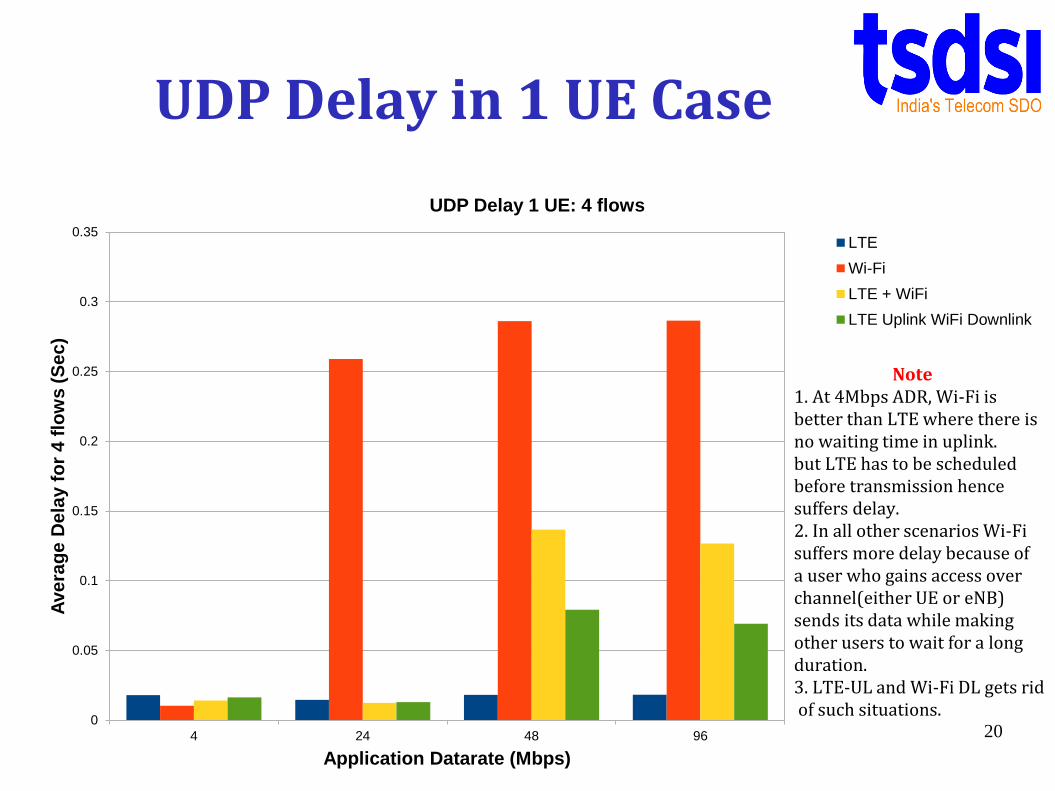
UDP Delay 1 UE: 4 flows
LTE
Wi-Fi
LTE + WiFi
LTE Uplink WiFi Downlink
Note1. At 4Mbps ADR, Wi-Fi is better than LTE where there isno waiting time in uplink.but LTE has to be scheduled before transmission hence suffers delay.2. In all other scenarios Wi-Fi suffers more delay because of a user who gains access over channel(either UE or eNB) sends its data while making other users to wait for a long duration.3. LTE-UL and Wi-Fi DL gets ridof such situations.
20
UDP Delay in 1 UE Case

0
0.5
1
1.5
2
2.5
3
3.5
16 32 64 128
Ag
gre
ga
te d
ela
y f
or
16
flo
ws
(S
ec
)
Application datarate (Mbps)
UDP Delay 4 UEs: 16 flows
LTE
Wi-Fi
LTE + WiFi
LTE Uplink WiFi Downlink
Note1. In all other scenarios Wi-Fi suffers more delay because of a user who gains access over channel(either one among4 UE or eNB) sends its datawhile making other users towait for a longer duration.
2. LTE + Wi-Fi gets reduced its Delay as ADR increases bczcontribution of Wi-Fi delay onLTE + Wi-Fi reduces.3.LTE-UL and Wi-Fi-DL still hasreduced delay because of no contention at Wi-Fi.
21
TCP Throughput in 4 UEs Case

Summary & Future work
• The most efficient static traffic steering mechanism w/o requiring any changes to protocol stack/hardware at UE is LTE (UL Data + UL/DL Control) and Wi-Fi (DL Data only).
• Further work needs to be conducted to study the benefits of dynamic traffic steering in both packet level and flow level settings
– Decision parameters need to be collected at Integrated Box to better estimate load, quality of radio links, etc
• Further work to study the effect of traffic steering on voice and video applications
22

References
• J. Ling, S. Kanugovi, S. Vasudevan, and A. Pramod, “Enhanced capacity and coverage by wi-fi lte integration,” Communications Magazine, IEEE, vol. 53, no. 3, pp. 165–171, March 2015
• Q. I. Intel Corporation, China Telecom. (2015) LTE-WLAN Radio Level Integration and Interworking Enhancement. [Online]. Available:www.3gpp.org/ftp/meetings_3gpp_sync/ran/Inbox/RP-150510.zip
• S.-I. Sou, “Mobile data offloading with policy and charging control in 3gpp core network,” Vehicular Technology, IEEE Transactions on, vol. 62, no. 7, pp. 3481–3486, 2013
• X. Kang, Y. Chia, S. Sun, and H. F. Chong, “Mobile data offloading through A third-party wifi access point: An operator’s perspective,” CoRR, vol. abs/1408.5245, 2014. [Online]. Available: http://arxiv.org/abs/1408.5245
• Tech Mahindra document shared on TSDSI (Scheduling perspective). 23

Recent updates on Interworking
• Intel proposed co-located architecture
• Qualcomm demonstrated (Feb 2015)
– Interworking ( at PDCP layer)
• Co-located and Non-collocated
– User Mobility (Moving user from LTE to Wi-Fi interface)
– load balancing (based on channel condition with MCS as a metric) ensures every node gets equal throughput
24


