36
WUEKRO Training & Didactic Systems Automation Technology with SIMATIC S7 Technology Stations/Simulators/Models Catalog WA2E/04.02

WUEKRO
Training & Didactic Systems Automation Technology with SIMATIC S7 Technology Stations/Simulators/Models
Catalog WA2E/04.02

WUEKRO
Page 2 Catalog WA2E/04.02
Our Services • Development and production of didactic training systems • Teachware and documentation • Project engineering of complete lab's incl. furniture and lab equipment • Quotations on customer's demand • Installation, commissioning and training at site
Our Customers • Vocational training schools, technical schools, colleges and universities... • Industrial laboratories for vocational education and higher education
Fields of Technology • Fundamentals of electrical engineering
• Fundamentals of electronics
• Closed loop control technology
• Automation engineering
• Electrical machines / drive control
• Power electronics
• Building management systems
• Protection schemes to VDE 0100
• Radio- and TV technology
• Air conditioning and refrigeration
• Photovoltaic
• Communication technology
• Measuring systems, power supplies, accessories
• Experimental manuals, documentation For further information please contact: WUEKRO GmbH Carl-Zeiss-Strasse 10 D - 97424 Schweinfurt Germany Tel. + 49 (0) 9721-64691-0 Fax: + 49 (0) 9721-64691-20 E-Mail: [email protected] Internet: www.wuekro.de WUEKRO GmbH All Rights reserved. Reprint not permitted. Technical changes without prior notice.. E20160525M – 05/16

WUEKRO
Catalog WA2E/04.02 Page 3
Table of Contents Page Our Services 2 Table of Contents 3 Training System Automation Technology 4 Introduction 5 Technology Simulators/General 6 Technology Simulators without Storage Function 6 Technology Simulators with Storage Function 7 Technology Simulators with Dynamic Response 8 Technology Simulators with Counters and Comparators 9 Technology Simulators Sequential Controls 10 Technology Simulators for Closed-Loop Control 12 Universal Simulators 14 Universal Simulator Electrical Engineering 14 Universal Simulator Mechanical Engineering 15 Plant Simulator Analog/Digital technology 16 Models 18 Conveyor Belt Model 18 Pneumatic Sheet bending Model 19 Elevator Model, 3 Storages 20 Conveyor Belt Compact Case 21 RFID Supplementary Kit 21 RFID Technology Set 21 Technology Stations 22 Technology Station Loading and Handling 22 Technology Station Conveyor Belt 23 Technology Station Measuring and Handling 24 Belt Technology Station High-Bay Warehouse 25 Accessories - Leads/Plugs 26 Experiment Instructions 27 Fax-Reply 28

WUEKRO
Page 4 Catalog WA2E/04.02
Training System Automation Technology
Educational Systems – Allocation – Target Groups Study projects Dissertations
Specialized practical training College/University
Aut
omat
ion
syst
ems
Basic practical training
College/University
Master craftsman/technician
Further education (Chamber of Industry and Commerce)
Skilled worker training N
ew te
chno
logi
es
Indu
stria
l bus
sys
tem
s
Fundamentals Training/education
SIM
ATI
C S
7 -
Expe
rimen
ter
Prog
ram
mab
le c
ontr
olle
rs, p
rogr
amm
ing,
in
dust
rial m
odel
s

WUEKRO
Catalog WA2E/04.02 Page 5
Introduction Your learning needs will be fulfilled with our training systems •
• •
•
•
•
•
• • • • • • • •
• •
• • • • • • •
Structure of numerical systems
Declaration of variables Methods of PLC
representation with FBL, LAD, STL, Graph 7, SCL according to standard IEC 1131-3
Getting to know program execution procedures
Getting to know the function groups of a PLC and their principles of operation according to standard IEC 1131-1,2
Basic logic operations with a PLC
Logic controls with dynamic response Counters and comparators with/without storage function Sequential controls with mode section Sequencers Operating status messages Process-oriented or time- oriented
Analog value processing Word processing Digital closed-loop control Autonomous modules Drive/position control Startup, maintenance Industrial networking Fundamentals of open
communications Process visualization/control Fault diagnostics without/with
visualization systems
The concept The aim of the new IEC 1131 standard is to attain a worldwide unified system in the field of PLC technology. The programming languages are standardized in part 3. The standard encompasses the ladder diagram (LAD), function block language (FBL), sequence language (SL), statement list (STL), and structured text (ST). PLC systems are an integral component of automation today. SIMATIC S7 has taken the lead by offering a basic system for the entire field of automation. SIMATIC S7 is the platform for
PLC Man-machine interface Industrial networking Process control engineering Automation computers Measurement and control DP applications
A great advantage for the user is the fact that this knowledge, once attained, can also be put to use in the other fields of technology. The goal of our training concept for the different fields of automation is to provide - Vocational schools - Colleges - Universities - Places of training and further education with the theoretical and practical prerequisites leading to trainees’ and students’ complete under-standing of modern automation technology.
In general, there are two ways in which you can fulfill your training needs: 1. By working with the low-cost
experimenter consoles and the technology simulators.
2. By working with the modular rack system, the technology simulators and models.
Here you can choose from the modules which are tailored to your curriculum. Our program is rounded off with the model industrial bus system, the modular automation system aimed at engineering schools and colleges/universities. Practical experiment instructions Experiment instruction manuals on the individual modules, which have been compiled by specially trained and qualified employees, are available for use. In general, the experiment instructions consist of three parts: Part 1 Introduces the training needs and provides the basic theory. Part 2 Contains the programming and test tasks. Part 3 Contains solutions to part 2. This keeps the time for test preparations to a minimum and offers a way of checking the results.
WUEKRO
Page 6 Catalog WA2E/04.02
Technology Simulators
General Technology diagrams in 3-D simplify the understanding of the illustrated process and optimize the periods of training. High-intensity LEDs symbolize sensors, actuators and operating states.
The material of the frontplate is of rigid, non-transparent PVC. The printing is scratch and solvent-resistant due to a double layer of protective lacquer. High-quality momentary-contact/maintained-contact switches with over 100,000 switching operations guarantee durability.
Thus, technology simulators with 3-D are a low-cost training alternative to models.
Logic controls without storage function
Logic controls without storage function are based on the application and combination of the basic logic functions: • NOT • AND • OR
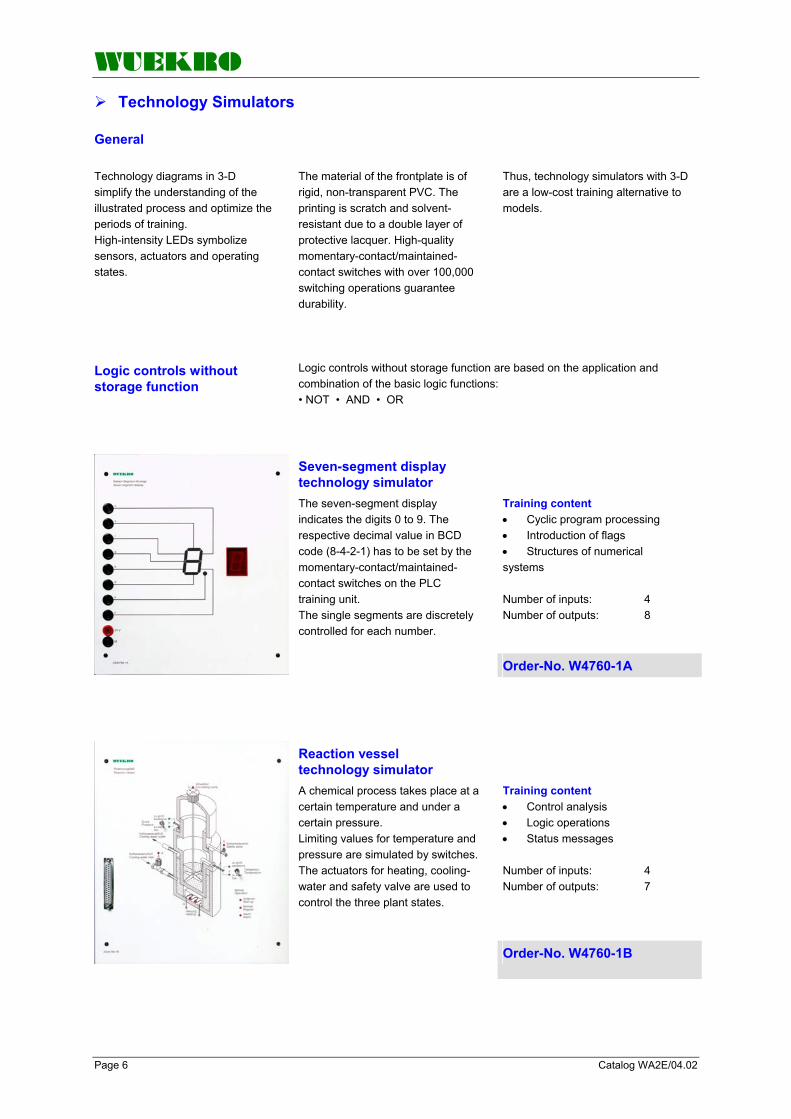
Training content • • •
Cyclic program processing Introduction of flags Structures of numerical
systems Number of inputs: 4 Number of outputs: 8
Seven-segment display technology simulator The seven-segment display indicates the digits 0 to 9. The respective decimal value in BCD code (8-4-2-1) has to be set by the momentary-contact/maintained-contact switches on the PLC training unit. The single segments are discretely controlled for each number.
Order-No. W4760-1A
Training content • • •
Control analysis Logic operations Status messages
Number of inputs: 4 Number of outputs: 7
Reaction vessel technology simulator A chemical process takes place at a certain temperature and under a certain pressure. Limiting values for temperature and pressure are simulated by switches. The actuators for heating, cooling-water and safety valve are used to control the three plant states.
Order-No. W4760-1B

WUEKRO
Catalog WA2E/04.02 Page 7
Technology Simulators
Logic controls with storage function
Many control tasks require a storage function.
This is available where a fleeting signal state is retained, i.e. stored.
Training content • • •
Interlock circuit Sequence control Storage types
Number of inputs: 6 Number of outputs: 3
Tank-filling device technology simulator Three storage tanks with sensors for “full” and “empty” indication are to be discharged in a random order. One tank with “empty” indication is to be filled until “full” is indicated. But only one tank is to be permanently filled. The tanks are to be filled in the same order in which they were emptied.
Order-No. W4760-1C
Training content • • • •
Truth table Pulse generator ON/OFF delay Process register
Number of inputs: 2 Number of outputs: 4
Pump control technology simulator Four motor-driven pumps deliver water from a suction tank into a pipeline. By switching the four pumps on and off in stages, the pressure in the mains is kept constant. The requirement is for the operating time of the pumps and the switching frequency to be as uniform as possible. Before switching the next stage on and off, an appropriate delay time is required. Order-No. W4760-1D

WUEKRO
Page 8 Catalog WA2E/04.02
Technology Simulators
Logic controls with dynamic response
The time generation is a basic binary function in control technology. Programmable „timers“ create a requested time-logic relationship between a start
signal at the input and a response signal at the output.
Training content • •
Time functions Interlock circuit
Number of inputs: 3 Number of outputs: 3
Automatic star-delta start-up technology simulator The start-up of a three-phase asynchronous motor is to be controlled via a star-delta controller. When pressing a pushbutton switch the motor first runs in star connection and is then automatically switched to delta connection. When pressing another switch or operating the overcurrent relay the motor is disconnected at all poles. Order-No. W4760-1E
Training content • • • •
Clock generator Pulse monitor of ON delays OFF delays Status messages
Number of inputs: 7 Number of outputs: 7
Belt control technology simulator The three conveyor belts are to be switched on and off via a pushbutton switch. Belt 1 and 2 are not to run simultaneously. Belt 3 is to automatically run at the time when belt 1 or 2 are conveying. Belt monitors signal the conveyor movement. The belts are to slow down with different times after the OFF button has been pressed. Faults are signaled by a flashing light. Order-No. W4760-1F
WUEKRO
Catalog WA2E/04.02 Page 9
Technology Simulators
Controls with counters and comparators
A certain set of values is often acquired by summating pulse. The corresponding pulses are passed to a counter which summates the received pulses.
Based on the compare functions, two digital values are compared with one another. The result of the comparison is binary and can be further processed.
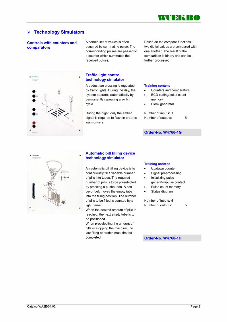
Training content • •
•
Counters and comparators BCD coding/pulse count
memory Clock generator
Number of inputs: 1 Number of outputs: 5
Traffic light control technology simulator A pedestrian crossing is regulated by traffic lights. During the day, the system operates automatically by permanently repeating a switch cycle. During the night, only the amber signal is required to flash in order to warn drivers.
Order-No. W4760-1G
Training content • • •
• •
Up/down counter Signal preprocessing Initializing pulse
generator/pulse contact Pulse count memory Status diagram
Number of inputs: 6 Number of outputs: 5
Automatic pill filling device technology simulator An automatic pill filling device is to continuously fill a variable number of pills into tubes. The required number of pills is to be preselected by pressing a pushbutton. A con-veyor belt moves the empty tube into the filling position. The number of pills to be filled is counted by a light barrier. When the desired amount of pills is reached, the next empty tube is to be positioned. When preselecting the amount of pills or stopping the machine, the last filling operation must first be completed. Order-No. W4760-1H

WUEKRO
Page 10 Catalog WA2E/04.02
Technology Simulators
Sequential controls
Sequential control is the control of a sequence of operations in individual steps. Switching from one step to the
following step is controlled by the control program in accordance with the “step enabling conditions”. The main property of the sequential control is that it can clearly assign individual steps to technological
procedures with respect to time and function. Consequently, distinction is made between “time-oriented” and “process-oriented” sequence control.
counter-clockwise rotation and also with creep speed. Training content • • • • • •
Word processing Positioning control Pulse contact Counters and comparators Prestructured status diagram Message display
Number of inputs: 5 Number of outputs: 4
Positioning control technology simulator Pieces of wood are cut true to dimensions on a saw table. For this purpose a stop is to be positioned from a control console with the help of an electric motor. The movement of the stop is measured with a shaft-angle encoder. Limit switches are located at the end position of the spindle, which are to prevent the stop from entering the restricted area. Prior to restart and cold restart of the installation, the reference point is to be approached. The spindle drive can be controlled in clockwise or Order-No. W4760-1J
Training content •
• • • • •
Process and time-oriented sequential control
Signal preprocessing Prestructured status diagram Structured sequencers Non-retentive flags Status messages
Number of inputs: 10 Number of outputs: 6
Two-door access control system technology simulator A dust-free room can be entered or left only through an air-lock with two automatically opening and closing doors. Light barriers monitor the entrances. In the case of an emergency the air-lock room can be opened or closed from within using additional door openers. Limit switches indicate the corresponding positions of the doors. All operating states are to be indicated via LEDs. Order-No. W4760-1K

WUEKRO
Catalog WA2E/04.02 Page 11
Technology Simulators
Training content •
• • • •
Process-oriented sequential control
Mode sections Step enabling conditions Protection against restart Controlled shutdown of a
system Number of inputs: 15 Number of outputs: 5
Embossing machine automatic simulator A workpiece that has been released from the hopper is pushed into a machining station where it is to be embossed for 3 s. A nozzle blows the blank out and an ejector pushes the workpiece into a collecting container. An operator panel as used in industry controls the operating modes “automatic” and “manual with inching mode”. The final positions of the electropneumatically operated valves are automatically indicated by the limit switches. Internal electronics automatically simulate the valve feed. Order-No. W4760-1L
Technology Simulators for Closed-Loop Control
Technical specifications Input voltage 1AC 230 V , 50 / 60 Hz Output voltage + 15 V / 1,5 A - 15 V / 1,5 A 24 V / 0,5 A Dimensions (WxHxD) 130x297x100 mm Weight approx. 3 kg
DC power supply Suitable for the supply of two filling level control technology simulators. designed as experimental panel height 297 mm for insertion into a compact unit or experimental frame. All connections are brought out to 4-mm-safety-sockets.
Order-No. W4610-4N
Experiment instructions V 175 “Digital Control I” with SIMATIC S7 Part 1: Fundamentals of digital control Part 2: Experiments from two- position control to continuous-action control Part 3: Solutions
Experiment instructions V 174 “Digital Control II” with SIMATIC S7 Part 1: Design study PID controller Part 2: Experiments, setting procedures Part 3: Solutions
Order-No. W3017-5B Order-No. W3017-4B

WUEKRO
Page 12 Catalog WA2E/04.02
Universal Simulators
Universal simulator electrical engineering
Teaching content (in conjunction with SIMATIC training units) • • • • • • • • • • • •
• •
• •
• • • •
• • • • • • • • • • •
Cyclic program processing Logic operations Interlock circuit Sequential circuit Storage types Pulse generator Edge evaluation Clock generator ON/OFF delay Counters and comparators Up/down counter BCD coding/pulse count
memory Signal processing Initializing pulse
generator/pulse contact Status diagram Process-oriented/time-oriented
sequential control Mode sections Sequencers Step enabling conditions Word messages
This simulator is especially suited for fundamental PLC training in the vocational field electrical engineering. The experiments have been aligned with the curriculum. The universal simulator is equipped with operator panel and simulator including overlays, and operates in a voltage range from 5 V...24 V DC. It is thus also suitable for applications from the fields of digital and microprocessor technology. Design Power +5V…24V is supplied via 4 mm safety sockets or 2 mm sockets, respectively. There are 8 freely assignable momentary-contact/maintained-contact switches mounted on the operator panel. The connectors of the switches are brought out to 4 mm safety sockets and to 2 mm sockets.
The 5 digital inputs for the simulator are also wired to 4 mm safety sockets and to 2 mm sockets. The scope of supply includes 11 different overlays with examples, ranging from simple logic control to sequential control.
Fan control Tank filling device Star-delta start-up Gate control Roadwork traffic light Pump control Starter control Oven door control Traffic light control Buffer control Sheet bending device
By replacing the overlays, the LEDs assigned to the respective exercise become visible.
Order-No. W4760-2A
• •
• •
•
Programming tasks for universal simulator W4760-2A with solutions for instructor and teacher, English
Experiment instructions V 179 Universal simulator Electrical Engineering
Programming to standard IEC 1131-3
Configuration of control tasks Instructions for setup and
programming Example of a consistent
configuration Order-No. W3017-9B

WUEKRO
Catalog WA2E/04.02 Page 13
Universal Simulators
Universal simulator Metal Engineering
Teaching content (in conjunction with SIMATIC training units) • •
•
• • •
• • • • •
• • • • • • • • • • •
Electropneumatics Electropneumatic signal flow
diagram Safety conditions in
installations with electropneumatics
Logic operations Interlock circuit Process-oriented/time-oriented
sequential control Storage types Counters and comparators Structured programming Status diagram Step enabling conditions
This simulator is especially suited for fundamental PLC training in the vocational field metal engineering. The experiments have been aligned with the curriculum. The universal simulator is equipped with operator panel and simulator including overlays, and operates in a voltage range from 5 V...24 V DC. It is thus also suitable for applications from the fields of digital and microprocessor technology. Design Power (+ 5 V ... 24 V) is supplied via 4 mm safety sockets or 2 mm sockets, respectively. There are 8 freely assignable momentary-contact/maintained-contact switches mounted on the operator panel. The connectors of the switches are brought out to 4 mm safety sockets and to 2 mm sockets.
The 8 digital inputs for the simulator are also wired to 4 mm safety sockets and to 2 mm sockets. The scope of supply includes 11 different overlays with examples, ranging from simple logic control to sequential control.
Punching device Lifting unit for packages Stamping device Lifting unit with sorting unit Positioning unit Forming station Press with safety installation Silo control for 2 bulk goods Quality testing installation Distribution unit Sorting unit
By replacing the overlays, the LEDs assigned to the respective exercise become visible.
Order-No. W4760-2B
• •
• •
•
Programming tasks for universal simulator W4760-2B with solutions for instructor and teacher, English
Experiment instructions V 189 Universal simulator Metal Engineering
Programming to standard IEC 1131-3
Configuration of control tasks Instructions for setup and
programming Example of a consistent
configuration Order-No. W3018-9B

WUEKRO
Page 14 Catalog WA2E/04.02
Universal Simulators
Plant Simulator Analog/Digital technology
Basic Unit Set of Overlays
V1 – Silo control V2 – Goods lift V3 – Traffic lights
V4 – 3-phase automatic starter V5 – Dahlander circuit V6 – Reversing contactor circuit
V7 – Star-delta circuit V8 – Running light V9 – Drink vending machinet
V10 – Reaction vessel V11 – Mixing unit V12 – Latching circuit
V13 – Multi storey car park V14 – Compressed air net V15 – Sequence control unit
V16 – Conveyor control V17 – Automatic tablet filler V18 – Tank filling system
V19 – Embossing machine V20 – Pump control

WUEKRO
Catalog WA2E/04.02 Page 15
Universal Simulators
•
• • • • • •
•
•
•
• • • •
• • • • • • • • • • • • • • •
•
• • • • • •
• • • • • • •
• •
Process and timed sequence control system
Mode sections Sequencers Step enabling conditions Word output Analog value processing Getting to know the
fundamentals of closed-loop control
Getting to know the tasks and elements of the controlling system
Getting to know the structure and method of operation of discontinuous controllers
Getting to know combination of controller and controlled system Technical data: 12 digital inputs on 4-mm safety lab sockets 12 digital outputs on 4-mm safety lab sockets 2 analog inputs on 4-mm safety lab sockets 2 analog outputs variable via potentiometers (0 - 10V) wires on 4- mm safety lab sockets 6 momentary-contact/ maintained- contact switch with LED status indicator 2 momentary-contact/ maintained- contact switch 1 Bargraph - display with 6 limit switches 1 system connector for 16 digital inputs and 16 digital outputs Power supply: 24 V DC Dimensions: (W x H x D) 390 x 297 x 100mm Weight: approx. 5 kg
Plant Simulator Analog/Digital Technology The universal simulator is especially suitable for the basic PLC training in the professional field of electrical engineering and metal-working technology. The experiments are tailored for the curriculum of vocational education. The inputs and outputs are internally wired to the simulation field matrix of the simulator and additionally connected to 4-mm safty lab sockets. The digital Inputs and Outputs are connected to a 37-pin D-SUB connector for an easy interconnection to SIMATIC Training-equipment. By exchanging the different text overlays, the sockets, switches, potentiometer and LED's, which are assigned to a specific exercise, are uncovered. This makes sure a clear setup of the exercises and avoids mistakes. Analog setpoint values can be adjusted by two potentiometers. The necessary power supply 24V can be supplied via 4-mm-safety sockets. The Universal Simulator can be used as an experimental panel in combination with an experimental frame or as an table-top unit.
Delivery includes 20 different text overlays with exercises dealing with the simple logic control, as well as analog value processing.
Silo control Goods lift Traffic lights Three phase automatic
starter Dahlander circuit Reversing contactor circuit Star-delta circuit Running light Drink vending machine Reaction vessel Mixing unit Latching circuit Multi-storey car park Compressed air net Sequence control circuit Conveyor control Automatic tablet filler Tank filling system Embossing machine
simulator Pump control
Training content
Cyclic program processing Logic circuits Interlocking circuit Sequential circuit Different memories Pulse generator, edge
evaluation Clock generator ON/OFF delay Counters and comparators Up/down counter BCD coding pulse count store Signal preprocessing Initializing pulse
generator/pulse contact Structured programming Status diagram Order-No. W4760-2C
Experiment instructions V 187 " Plant Simulator"
•
• •
• Programming acc. to standard IEC 1131-3
Projecting of controls One task for each overlay
Programming tasks for plant simulator W4760-2C with solutions for teacher, english language
Order-No. W3018-7B

WUEKRO
Page 16 Catalog WA2E/04.02
Models for Training Units with SIMATIC S7
Industrial application Models of complex industrial installations ensure that training is close to practice and are suitable for imparting specific fundamental
knowledge in the fields electrotechnical engineering, pneumatics, material flow, design and sensor technology.
The purpose is to learn to deal with technical devices in a technical way using the proper instruments.
Training content Material flow technology Startup Troubleshooting Maintenance Process-oriented sequential control Sequencer programming
Conveyor belt model For training in programmable logic control and material flow technology.
Consists of aluminum profile rails and a built-on 24 V DC industrial motor, spherically seated concave belt rollers, non-slip, rubber-coated fabric belt. Connection to SIMATIC training unit via 37-pin D-SUB plug.
Order-No. W4761-1B
Consists of: 2 sensors: inductive S=15 mm optical 3 transport containers out of aluminum, black plastic and white plastic 2 fastening angles
Supplementary kit Sensor Technology Supplementary kit Sensor Technology for conveyor belt model W4761-1B.
All cable ends are fitted with 2 mm connectors.
Order-No. W3545-6J
Connecting lead With 37-pin subminiature D-SUB plug (model side) and 1 x 37-pin D-SUB plug for connection to the SIMATIC S7 training units. Order-No. W4760-8A

WUEKRO
Catalog WA2E/04.02 Page 17
Models for Training Units with SIMATIC S7
Training content •
• •
•
Reading and applying pneumatic circuit diagram
Creating sequencer Process-oriented sequential
control system Getting to know safety-related
precautions in electro- pneumatic installations Number of inputs: 8 Number of outputs: 6 Experiment instructions are part of the scope of delivery.
Pneumatic model Sheet Bending Device Sheet is to be bent by means of three 5/2-way valves, which are electropneumatically actuated on both sides. The device is to be wired up using the pneumatic circuit diagram, and the control program is to be created. The device can be isolated by a pneumatic Emergency-Stop switch. All terminals are wired to 4 mm safety sockets. For operation, a compressed-air supply of 6 bar is required. The maximum sheet thickness which can be processed is 0.5 mm.
Order-No. W4761-1C
Technical specifications: Supply voltage 1 AC 230 V 50/60 Hz Power 340 W Volume 4 l/340 W Output 56 l/min Admissible operating pressure 8 bar Weight approx. 20 kg
Compressor Fits the pneumatic model W4761-1C.
Order-No. W3545-8A

WUEKRO
Page 18 Catalog WA2E/04.02
Models for Training Units with SIMATIC S7
Elevator Model 3 storages Features Didactic elavator model with elevator cage over 3 floors. The desired floor can be selected by illuminated pushbuttons. When the elevator cage reaches the appropriate floor, sensors issue a signal. The lowest cage position has an endpoint-overflow, which is signalized by a LED. The reset can be controlled by a built-in push-botton. An integrated switch in the operator panel causes an emergency stop function (motor deactivation).
A 7 segment display enables to diplay the reached floor (only connected to the 37-pin D-SUB-socket) The in- and outputs are connected to 4mm safety lab sockets and additionally to the 37-pin D-SUB-socket Learning contents: · Process-controlled sequence control · Commissioning · Symbolic addressing · Mode sections Number of inputs: 5 (7 via 37pin SUB-D socket) Number of outputs: 7 (9 via 37pin SUB-D socket) Dimensions (W x H x D) 200x680x260mm Weight : approx. 7 kg
Order-No. W3545-6A

WUEKRO
Catalog WA2E/04.02 Page 19
Models for Training Units with SIMATIC S7 Conveyor belt case with varous equipment, safely packed attached in a compact formcase. The conveyor belt (lenght approx. 310mm, width approx. 40mm) runs smoothly on the inbuilt case-baseplate. The drive motor with integrated incremental encoder is unvisibly mounted under the baseplate; so with appropriate programming a direct drive to a certain postion is possible.
Cylindrical test pieces (diameter approx. 30mm, Hight approx. 20mm) with different filling materials (Aluminium, white and black plastic and wood) are feeded from the magazine with an electrical pusher to the conveyor belt which transports the test item passing different sensors (inductive, capacitive and optical) and also a ultrasonic-sensor as an analogue one. Two additional electrical pushers allow a sorting of the test items.
2 light barriers avoid the “stock-overflow” (ex 2 test items in the storage area). A substantial operator control panel enables a direct “on-site-attendance” of the device. This panel includes 3 illuminated pushbottons (“START”, “STOP”, “FC”), mode-switch (e.g. semi-automatic-system or machine-setup-control), 2x2 signal lamps (“LA1”, “LA2”, quality “Yes”, “No”).
Training content programmable logic control Material flow technology Startup Troubleshooting Maintenance Process-oriented sequential control Sequencer programming analog value processing sensor technology control panel device Order-No. W4764-4A
Supplementary kit RFID Technology Extension set for the conveyor belt model compact case W4764-4A to dive into the wide field of radio identification with RFID (Radio Frequency Identification)
Scope of delivery: Experimenter panel W4764-4AZ-RFID communication-module SIMATIC RF180C with Ethernet hub as interface to the CPU.
Scope of delivery (cont.): 2 RFID Read and Write modules fixed on a plexiglass plate with all necessary accessories like cables, wires and screws. Easily to be fixed at the holder of the ultrasonic sensor of W4764-4A with 4 screws. 6 Sample pieces of different height made out of black or white plastic or metal, equipped with a RFID transponder chip
Order-No. W4764-4A-Z (only supplementary kit without case) Complete RFID case: W4764-4A-RFID
Station in action
RFID Technology Station Set Illustration: W4734-1V-PN/DP SIMATIC S7 Rack W4751-1U-Kit optional Touchpanel built in Rack W4764-4A-RFID (=W4764-4A + W4764-4A-Z) Technology station RFID with testing and sorting station W4760-8A Connecting lead
WUEKRO
Page 20 Catalog WA2E/04.02
Technology Stations
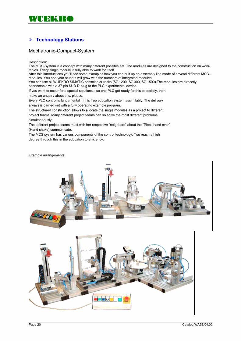
Mechatronic-Compact-System Description: The MCS-System is a concept with many different possible set. The modules are designed to the construction on work-tables. Every single module is fully able to work for itself. After this introductions you’ll see some examples how you can buit up an assembly line made of several different MSC- modules. You and your studets will grow with the numbers of integrated modules. You can use all WUEKRO SIMATIC consoles or racks (S7-1200, S7-300, S7-1500).The modules are direcetly connectable with a 37-pin SUB-D-plug to the PLC-experimental device. If you want to occur for a special solutions also one PLC got ready for this especially, then make an enquiry about this, please. Every PLC control is fundamental in this free education system assimilably. The delivery always is carried out with a fully operating example program. The structured construction allows to allocate the single modules as a project to different project teams. Many different project teams can so solve the most different problems simultaneously. The different project teams must with her respective "neighbors" about the "Piece hand over" (Hand shake) communicate. The MCS system has various components of the control technology. You reach a high degree through this in the education to efficiency. Example arrangements:

WUEKRO
Catalog WA2E/04.02 Page 21
Technology Stations
Loading, check and handling
Teachware : · Training material for the technology station Loading and handling Extent of supply: • • •
•
•
•
1 Loading magazine 1 Profile plate complete 1 Set of 6 workpieces
1 Technical documentation Technical data :
Dimensions (WxDxH): 160 x 400 x 340 mm
Weight : 2,7kg Optional addition:
· Mobile underframe (Order-No.: W4764-5U) · Control panel (Order-No.: W4764-6A) Neccessary Accessories Connecting lead to SIMATIC Training unit (Order-No. W4760-8A) Air compressor (Order-No. W3545-8A)
Order-No. W4764-5A
Mechatronic Station Loading, check and handling Didactic indications : The technology station negotiates awareness of function and application of industrial componentsof the branch feeding of stock and handling.By means of the didactic prepared industry components, the physical function principles, connecting technique and variants to the material provision are practically presented. The station with the typical interfaces to the mechanics, pneumatics, electrical engineering/electronics and PLC-technique, is especially suitable to the approach in the multiple fields of the MECHATRONICS.
As individual station in the teaching or during the exercises in the lab, the station can be used quick and uncomplicated and it can be set into operation independently. Structure : •
• • • • •
· Magazine with pneumatic double-acting thruster
Technical data : · 6 digital inputs , · 2 digital outputs · necessary working
pressure :min. 5 bars , max. 6 bars
WUEKRO
Page 22 Catalog WA2E/04.02
Technology Stations
Pick and place
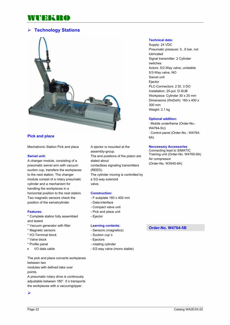
Technical data: Supply: 24 VDC Pneumatic pressure: 5...6 bar, not lubricated Signal transmitter: 2 Cylinder switches Actors: 5/2-Way valve, unistable 5/3-Way valve, NO Swivel unit Ejector PLC-Connectors: 2 DI, 3 DO Installation: 25-pol. D-SUB Workpiece: Cylinder 30 x 20 mm Dimensions (WxDxH): 160 x 400 x 300 mm Weight: 2.1 kg Optional addition: · Mobile underframe (Order-No.: W4764-5U) · Control panel (Order-No.: W4764-6A) Neccessary Accessories Connecting lead to SIMATIC Training unit (Order-No. W4760-8A) Air compressor (Order-No. W3545-8A)
Order-No. W4764-5B
Mechatronic Station Pick and place Swivel unit: A changer module, consisting of a pneumatic swivel arm with vacuum suction cup, transfers the workpieces to the next station. The changer module consist of a rotary pneumatic cylinder and a mechanism for handling the workpieces in a horizontal position to the next station. Two magnetic sensors check the position of the swivelcylinder. Features: * Complete station fully assembled and tested * Vacuum generator with filter * Magnetic sensors * I/O-Terminal block * Valve block * Profile panel • I/O data cable The pick and place converts workpieces between two modules with defined take over points. A pneumatic rotary drive is continously adjustable between 180°. It´s transports the workpieces with a vacuumgripper.
A ejector is mounted at the assembly-group. The end positions of the piston are stated about contactless signaling transmitters (REED). The cylinder moving is controlled by a 5/2-way solenoid valve. Construction: - F-subplate 160 x 400 mm - Data-interface - Compact valve unit - Pick and place unit - Ejector Learning contents: - Sensoric (magnetics) - Suction cup´s - Ejectors - rotating cylinder - 5/2-way valve (mono stable)
WUEKRO
Catalog WA2E/04.02 Page 23
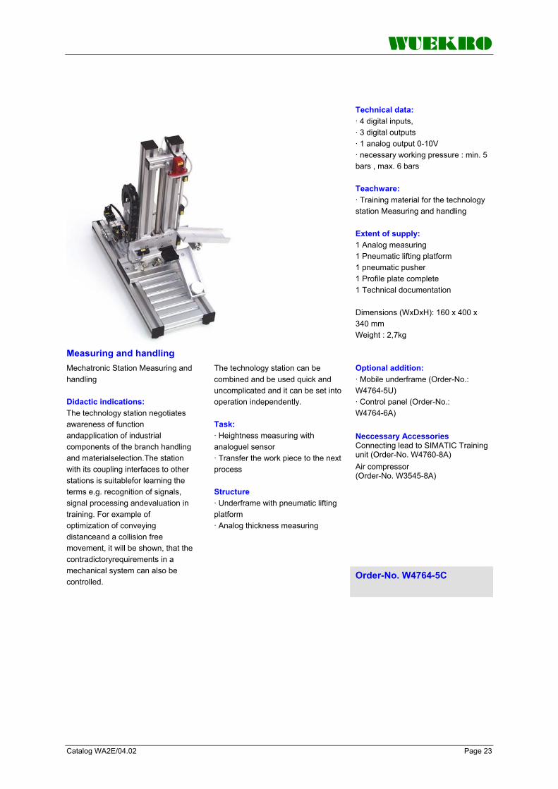
Measuring and handling
Technical data: · 4 digital inputs, · 3 digital outputs · 1 analog output 0-10V · necessary working pressure : min. 5 bars , max. 6 bars Teachware: · Training material for the technology station Measuring and handling Extent of supply: 1 Analog measuring 1 Pneumatic lifting platform 1 pneumatic pusher 1 Profile plate complete 1 Technical documentation Dimensions (WxDxH): 160 x 400 x 340 mm Weight : 2,7kg
Optional addition: · Mobile underframe (Order-No.: W4764-5U) · Control panel (Order-No.: W4764-6A) Neccessary Accessories Connecting lead to SIMATIC Training unit (Order-No. W4760-8A) Air compressor (Order-No. W3545-8A)
Mechatronic Station Measuring and handling Didactic indications: The technology station negotiates awareness of function andapplication of industrial components of the branch handling and materialselection.The station with its coupling interfaces to other stations is suitablefor learning the terms e.g. recognition of signals, signal processing andevaluation in training. For example of optimization of conveying distanceand a collision free movement, it will be shown, that the contradictoryrequirements in a mechanical system can also be controlled.
The technology station can be combined and be used quick and uncomplicated and it can be set into operation independently. Task: · Heightness measuring with analoguel sensor · Transfer the work piece to the next process Structure · Underframe with pneumatic lifting platform · Analog thickness measuring Order-No. W4764-5C

WUEKRO
Page 24 Catalog WA2E/04.02
Technology Stations
Sorting and handling
Technical data: · 4 digital inputs, · 3 digital outputs · necessary working pressure : min. 5 bars , max. 6 bars Teachware: · Training material for the technology station Sorting and handling Extent of supply: 1 Complete station fully assembled and tested 1 Profile plate complete 1 Reflex light barrier 1 Fork light barrier 2 Magnetic sensors Optional addition: · Mobile underframe (Order-No.: W4764-5U) · Control panel (Order-No.: W4764-6A) Neccessary Accessories Connecting lead to SIMATIC Training unit (Order-No. W4760-8A) Air compressor (Order-No. W3545-8A)
Order-No. W4764-5D
Mechatronic Station sorting and handling Didactic indications: The technology station negotiates awareness of function and application of industrial components of the branch handling and material selection The station with its coupling interfaces to other stations is suitable for learning the terms e.g. recognition of signals, signal processing and evaluation in training. For example of optimization of conveying distance and a collision free movement, it will be shown, that the contradictory requirements in a mechanical system can also be controlled.
The technology station can be combined and be used quick and uncomplicated and it can be set into operation independently. Task: · Sorting according to the material properties · Positioning of a linear drive through fork light barrier Structure: · electric linear drive · 3 slides – filling is monitored using an optical reflex sensor · workpiece holder with pneumatic pusher

WUEKRO
Catalog WA2E/04.02 Page 25
Technology Stations
Drilling and handling
Teachware: · Training material for the technology station Drilling and handling Extent of supply: 1 Electric drill module 1 Pneumatic work piece holder 1 Profile plate complete 1 Hardware 1 Technical documentation Optional addition: · Mobile underframe (Order-No.: W4764-5U) · Control panel (Order-No.: W4764-6A) Neccessary Accessories Connecting lead to SIMATIC Training unit (Order-No. W4760-8A) Air compressor (Order-No. W3545-8A)
Order-No. W4764-5E
Mechatronic Station Drilling and handling Didactic indications: The technology station negotiates awareness of function and application of industrial components of the branches material processing and handling. Using the example of the machining method drilling, the signals and the safety-technical contexts are imposing confronted. The didactical prepared components are clearly developed for the training. Complex tasks with higher level can be done for the branch maintenance. So the maintenance time and the operational hour counter can be recorded in the control program for controlling the wear of tools (drills).
The technology station can be used as single station or in combination with others. Task: · Drilling the work piece · Convey the work piece to the next process Structure: · 24V DC drilling machine with pneumatic infeed · Pneumatic work piece holding Technical data: · 4 digital inputs, · 4 digital outputs · necessary working pressure : min. 5 bars , max. 6 bars

WUEKRO
Page 26 Catalog WA2E/04.02
Technology Stations
Storage and handling
Technical data: · 2 digital inputs, · 6 digital outputs · necessary working pressure : min. 5 bars , max. 6 bars Teachware: · Training material for the technology station Storage and handling. Extent of supply: 3 Deposit thrust 1 Electrical gripper with suction 1 Profile plate complete 1 Technical documentation Optional addition: · Mobile underframe (Order-No.: W4764-5U) · Control panel (Order-No.: W4764-6A) Neccessary Accessories Connecting lead to SIMATIC Training unit (Order-No. W4760-8A) Air compressor (Order-No. W3545-8A)
Order-No. W4764-5G
Mechatronic Station Storage and handling Didactic indications: The technology station negotiates awareness of function and application of modules for storing and handling of work pieces of different forms and structure. By means of a practicable example, the possibilities and the limits can be used at the didactic prepared industrial components with electropneumatical and electromechanical modules. The safety requirements referring to the switching off can be approached in the lab.
The connection, the wiring and the adjusting of stop position switch as well as the inquiry in the control program can be approached with this station. The technology station can be used as single station or in combination with others. Task: · Deposit acc. to the material properties and form Structure: · Deposit unit with three thrust · Electrical gripper with suction

WUEKRO
Pneumatic pick and place with gripper
Technical data: · 4digital inputs, · 4 digital outputs Teachware: · Training material for the technology station Extent of supply: 1 Pneumatic gripper 1 Profile plate complete 1 Technical documentation Optional addition: · Mobile underframe (Order-No.: W4764-5U) · Control panel (Order-No.: W4764-6A)
Order-No. W4764-5H
Mechatronic Station Pneumatic pick and place with gripper Didactic indications: The technology station negotiates awareness of function and application of modules for storing and handling of work pieces of different forms and structure. By means of a practicable example, the possibilities and the limits can be used at the didactic prepared industrial components with electropneumatical and electromechanical modules. The safety requirements referring to the switching off can be approached in the lab.
The connection, the wiring and the adjusting of stop position switch as well as the inquiry in the control program can be approached with this station. The technology station can be used as single station or in combination with others. Task: · Workpieces are fteched of another module at thefirst position and promoted in the circle with a suction gripper Structure: · Pneumaitc gripper
Mechatronic Station electric pick and
place with gripper Similar device as aforesaid, but operated with electric pick and place gripper
Order-No. W4764-5H-G
Mechatronic Station electric pick and
place with sucktion device Similar device as aforesaid, but operated with electric pick and place sucktion device
Order-No. W4764-5H-S
Catalog WA2E/04.02 Page 27
Technology Stations

WUEKRO
Page 28 Catalog WA2E/04.02
Technology Stations
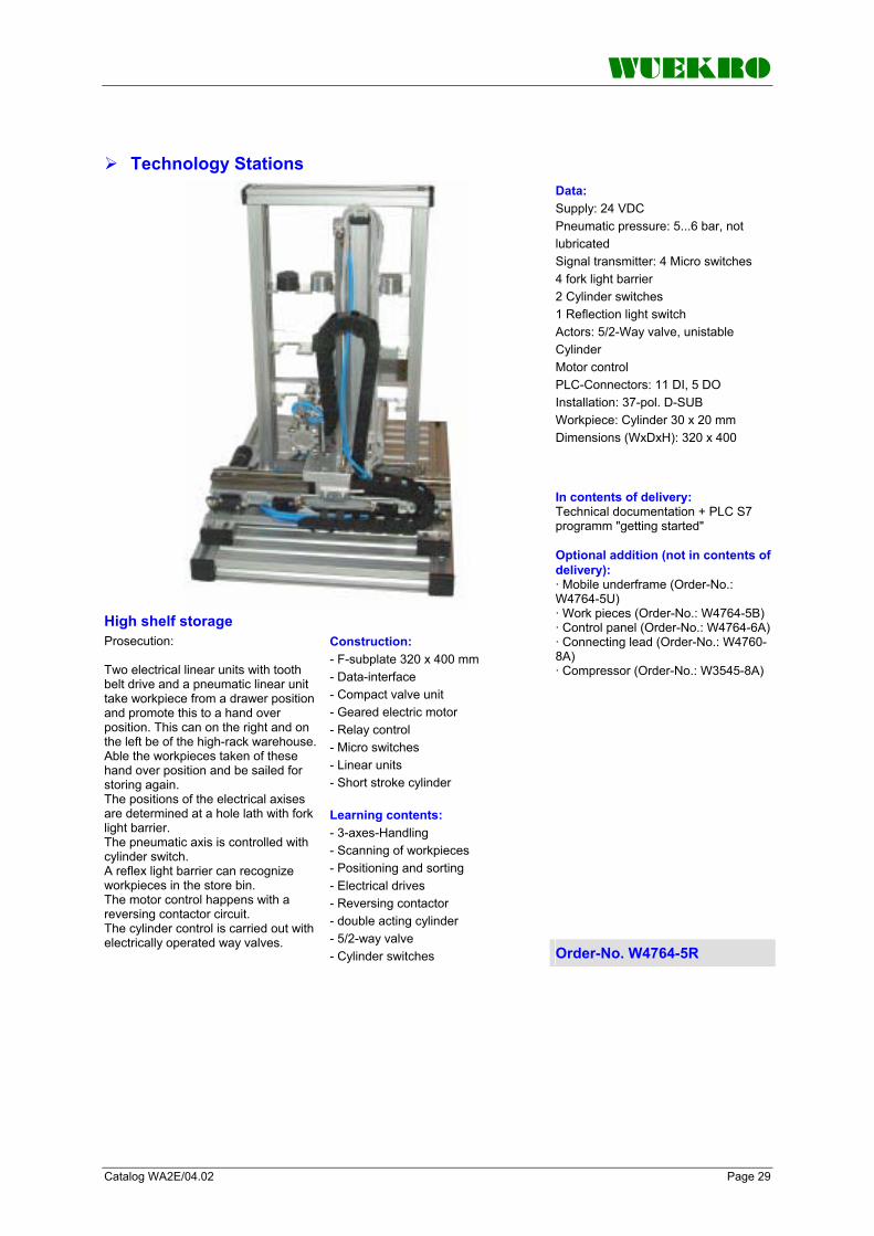
High shelf storage
Y-axis: The Y-axis is pneumatically controlled by a torsion-free cylinder. The positioning is done at a hole lath with a fork light barrier. For the collection of the impulses a counter input of the control is necessary. Z-axis: The Z-axis is pneumatically controlled by a torsion-free cylinder and has only got 2 states. "Gone-in" is the transport position of the work pieces and "gone-out", the work pieces are put down or picked up. Technical Data: Signal transmitters: - 7 cylinder switches - 2 fork light barriers - 2 micro switches Actuators: - 1 5/2-directional control valve, monostable - 1 5/3-directional control valve Compressed air not oiled from 5 up to 6 bar Power supply 24V DC Installation 37-pin. D-Sub-plug Work pieces: 1 Cylinder Ø30 x 20 mm Dimensions: 320 x 400 x 450
Mechatronic Station High shelf storage With the high shelf storing, you can store 12 work pieces of a diameter Ø 30 mm and of 20 mm height with a 3-axis handling system in 3 floors with 4 storing places each. The work pieces can be picked up or placed from a position being in a distance of 85 mm on the right or left side of the assembly plate. The 3-axis handling system consists of one electrically driven axis and two pneumatically driven axis. Construction: - AL-T-slot plate 320x400x450 mm - 2 relay functional modules as reversing contactor circuit - Valve island with 5/2 control valves, unistable - High shelf store made out off aluminum elements with 12 storing places and 3-axis handling system
Function: X-axis: The X-axis is driven with a d. c. motor 24V DC via tooth belt drive. The final positions are protected with a micro switch as final position switch. At the same time, this switch is available as DU at the control and can be used as reference point. The positioning is done with a fork light barrier in defined positions for the deposit positions and the take-over (transfer). The correction of the transfer position is done by positioning of the whole high-shelf storing in X-direction. For the collection of the position the usual DU of a PLC (SPS) are sufficient.
Order-No. W4764-5R Prosecution next page
WUEKRO
Catalog WA2E/04.02 Page 29
Technology Stations
High shelf storage
Data: Supply: 24 VDC Pneumatic pressure: 5...6 bar, not lubricated Signal transmitter: 4 Micro switches 4 fork light barrier 2 Cylinder switches 1 Reflection light switch Actors: 5/2-Way valve, unistable Cylinder Motor control PLC-Connectors: 11 DI, 5 DO Installation: 37-pol. D-SUB Workpiece: Cylinder 30 x 20 mm Dimensions (WxDxH): 320 x 400 In contents of delivery: Technical documentation + PLC S7 programm "getting started" Optional addition (not in contents of delivery): · Mobile underframe (Order-No.: W4764-5U) · Work pieces (Order-No.: W4764-5B) · Control panel (Order-No.: W4764-6A)· Connecting lead (Order-No.: W4760-8A) · Compressor (Order-No.: W3545-8A)
Prosecution: Two electrical linear units with tooth belt drive and a pneumatic linear unit take workpiece from a drawer position and promote this to a hand over position. This can on the right and on the left be of the high-rack warehouse. Able the workpieces taken of these hand over position and be sailed for storing again. The positions of the electrical axises are determined at a hole lath with fork light barrier. The pneumatic axis is controlled with cylinder switch. A reflex light barrier can recognize workpieces in the store bin. The motor control happens with a reversing contactor circuit. The cylinder control is carried out with electrically operated way valves.
Construction: - F-subplate 320 x 400 mm - Data-interface - Compact valve unit - Geared electric motor - Relay control - Micro switches - Linear units - Short stroke cylinder Learning contents: - 3-axes-Handling - Scanning of workpieces - Positioning and sorting - Electrical drives - Reversing contactor - double acting cylinder - 5/2-way valve - Cylinder switches Order-No. W4764-5R

WUEKRO
Page 30 Catalog WA2E/04.02
Technology Stations
Processing & Handling
Learning contents : - Positioning of pieces - Electrical drives - Material control with different sensors - Module technics Optional addition: · Mobile underframe (Order-No.: W4764-5U) · Control panel (Order-No.: W4764-6A) Neccessary Accessories Connecting lead to SIMATIC Training unit (Order-No. W4760-8A) Air compressor (Order-No. W3545-8A)
Order-No. W4764-5T
Mechatronic Station Processing & Handling Rotary index table The rotary index table, driven electrically promotes workpieces in the circle and places this in the angle of 90 °. The workpieces must be put on the rotary index table and taken by other unities. A check unit mounted over the rotary index table with three sensors recognizes the workpieces when "present", "bright", "dark" and "metallic". The results can be displayed on the indication. The 90 ° positions are included with an inductive sensor. The motor control is carried out with a relay. Features * Complete station fully assembled and tested * 1 optical sensor * 2 inductive sensors * Capacitive sensor * Profile panel Technical data: · 4 digital inputs, · 4 digital outputs
Teachware: · Training material for the technology station Processing and handling with electric rotary indexing table Data: - Supply: 24 VDC - Pneumatic pressure: 5...6 bar, unot lubricated - Signal transmitter: 2 inductive sensors - 1 capacitiv sensor - 1 optical sensor - Actors: 1 Motor control - LED units - PLC-Connectors: 4 DI, 4 DO - Installation: 37-pol. D-SUB - Workpiece: Cylinder 30 x 20 mm - Dimensions (WxDxH): 320 x 400 x 295 mm - Weight: 4.8 kg Construction: - F-subplate 160 x 400 mm - Data-interface - Compact valve unit - Geared electric motor - Relay control - Sensor, inductive - Check unit - Display unit

WUEKRO
Catalog WA2E/04.02 Page 31
Technology Stations
Accessories set and small parts
- 1 End cap for Aluminium-Profile 20x40 - 2 End caps for Aluminium-Profile 40x80 - 9 Workpieces D 30 mm consist of: Aluminium:2 x H=20 mm, 1 x H=21 mm , 1 x H=19 mm Plastics black: 2 x H=20 mm Plastics white: 3 x H=20 mm Note: The accessories are not included in the modules. To control a big solution, consist of 4 modules, one accessories set are neccessary.
Tool box, Accessories set and small parts Consisting of: - 1 Storing box - 1 Screwdriver - 1 Allen key set
- 1 Tube cutter - 6 Connectors to connect different modules - 2 End caps for Aluminium-Profile 20x20 - 2 End caps for Aluminium-Profile 20x30 Order-No. W4764-5P
Accessories Service unit, Preparation unit
Note: The preparation unit is only includes at W4764-5A module, not included in the other module´s. When you wish to control a big solution consist of many modules, you need only one preparation unit. When you wish to control single module s, then you need for every module a preparation unit. Preparation unit
Filter and pressure regulator with half automatically water separator, Filter body in polycarbone Pressure regulating valve with gauge, adjustable and lockable
Features * 3/2-Way-shut off valve * Connector for tube 6/4 * adjustable area 0,5 till 7 bar
Order-No. W4764-5S
Acessories technology stations Prepared for combining a shuttle-installation
Mobile underframe Mobile underframe with swivel castor and 4 vertical profile-bars on wich the mounting plate is fixed.
The cross-system connection elements enable the docking-on from other mobile underframes left- and righthand.
Order-No. W4764-5U
Acessories technology stations Set of quickconnectors = 2 pieces Connector for technology stations for
mechanical connection. Quickconnector for connecting of single frame plates / technology stations.
Order-No. W4764-5V

WUEKRO
Page 32 Catalog WA2E/04.02
Accessories - Leads/Plugs
Workpiece set, 6 pieces
consisting of: 1 xworkpieces, Metal, h=20mm 1 x workpieces, PVC, white, h=20mm 1 x workpiecesk,PVC, black, h=20mm 1 xworkpieces, Metal, h=22mm 1 x workpieces, PVC, white, h=22mm 1 x workpiecesk,PVC, black, h=22mm Order-No. W4764-5W
Workpiece set, 30 pieces
consisting of: 10 xworkpieces, Metal, Aluminium 10 x workpieces, PVC, white 10 xworkpieces, PVC, black Order-No. W4764-5Z
Connecting lead
32 A/250 V, black, 100 cm long, with 4 mm safety plug
Order-No. W3907-3E
Connecting lead
32 A/250 V, red, 100 cm long, with 4 mm safety plug
Order-No. W3907-3F
Adapter
4 mm plug/2 mm socket for connection of 2 mm connecting leads
Order-No. W3942-2A
Connecting lead
37-pin D-SUB plug on both sides, 1.5 m long, for connection of technology simulators to SIMATIC S7 training units
Order-No. W4760-8A
(W X H X D): 15,8 X 54 X 34 mm Terminat. resistor with isolat. function without PG socket
Connector for PROFIBUS SIMATIC DP, Bus Connector for PROFIBUS up to 12 MBIT/S 90 degree angle outgoing cable
Order-No. W3947-1A
(W X H X D): 15,8 X 54 X 34 mm Terminat. resistor with isolat. function with PG socket
Connector for PROFIBUS SIMATIC DP, Bus Connector for PROFIBUS up to 12 MBIT/S 90 degree angle outgoing cable
Order-No. W3947-1B

WUEKRO
Catalog WA2E/04.02 Page 33
shielded special design for rapid installation, 20 m
PROFIBUS – Cable SIMATIC NET, PB FC Standard Bus Cable, 2-Wire,
Order-No. W3947-2A
shielded special design for rapid installation, 50 m
PROFIBUS – Cable SIMATIC NET, PB FC Standard Bus Cable, 2-Wire,
Order-No. W3947-2B
shielded special design for rapid installation, 100 m
PROFIBUS – Cable SIMATIC NET, PB FC Standard Bus Cable, 2-Wire,
Order-No. W3947-2C

WUEKRO
Page 34 Catalog WA2E/04.02
Experiment Instructions
Practical experiment instructions
Experiment instruction manuals on all SIMATIC training systems, which have been compiled by specially trained and qualified employees, are available for use. In general, the experiment instructions consist of three parts: Part 1: Fundamentals Introduces the training needs and provides the basic theory Part 2: Experiments Contains the experiments like programming and test tasks Part 3: Solutions Contains solutions to Part 2, offers ways of checking the results and thus reduces the time for test preparation
Experiment instructions A = German B = English
V172 SIMATIC S7-200 Order-No. W3017-2_
V173 SIMATIC S7-300 Order-No. W3017-3_
V175 Digital Control I with SIMATIC S7 Order-No. W3017-5_
V174 Digital Control II with SIMATIC S7 Order-No. W3017-4_
V176 PROSIM 95 (Process simulation) Order-No. W3017-6_
V177 FUZZY-Logic Order-No. W3017-7_
V178 PROFIBUS DP Order-No. W3017-8_
V179 Universal Simulator Electrical Engineering Order-No. W3017-9_
V189 Universal Simulator Metal Engineering Order-No. W3018-9_
V187 Plant Simulator Order-No. W3018-7_
V188 Contactor Control with SIMATIC S5/S7 Order-No. W3018-8_

WUEKRO
Catalog WA2E/04.02 Page 35

WUEKRO
Page 36 Catalog WA2E/04.02
FAX – response to: +49 (0)9721 - 64691 - 20 Sender: Receiver:
Company WUEKRO GmbH Dept. Sales Department Name Street Carl-Zeiss-Strasse 10 City 97424 Schweinfurt/ Germany Phone + 49-(0)9721-64691-0 Fax + 49-(0)9721-64691-20 E-Mail [email protected] Internet www.wuekro.de No. of pages incl. this page
Please send the following catalogues to the a.m. address! Fundamentals of electrical Engineering
Installation circuits Bell ringing and entrance call stations Contactor control / Control technology Measurement and control of non-electrical variables
Fundamentels of electronics Analog technology Digital technology Microprocessing technology
Closed loop control technology Analog closed loop control Digital closed loop control
Automation engineering SIMATIC S7-200/300/400, Software Technology simulators / Models Process control engineering PCS7 AS-Interface Profibus DP Process simulation-software SIMIT LOGO! Mechatronical technology stations Courses on Automation
Electrical machines / Drive controls Electrical Machines 300W Electrical Machines 1000W Electrical Machines 5kW Electrical drive control systems 300W/ 1kW Electrical drive control systems 5kW Networked drive systems Cutaway Models Transformers, Rectifiers and Reactive Power Compensation Courses on drive systems
Power electronics extra low voltage (24V) low voltage (230/400V)
Building management systems instabus EIB
VDE 0100 safety measures
Radio- and Television engineering AM/FM – Technology TV Engineering Video, CD, DVD Satellite – Technology
Cooling and air conditioning
Photovoltaic cell tecnology
Communication technology Modulation -/demodulation Fiber optic ISDN
Measuring systems
Power supply units
Experiment instructions, manuals
Training courses
Remarks:


