16
_,. TRAINING HANDBOOK 9503.1, 9503 .2 Autolite Model 4300 CARBURETOR Operation, Adjustment EJD> and Overhaul SERVICE TRAINING VOL. 67 52 L2 Official Licensed Product license #2013226

_,.
TRAINING HANDBOOK 9503.1, 9503.2
Autolite Model 4300
CARBURETOR Operation, Adjustment EJD> and Overhaul
SERVICE TRAINING
VOL. 67 52 L2
Official Licensed Product
license #2013226

Copyright © 2014, Forel Publishing Company, LLC, Woodbridge, Virginia
All Rights Reserved. No part of this book may be used or reproduced in any manner whatsoever without written permission of Forel Publishing Company, LLC. For information write to Forel
Publishing Company, LLC, 3999 Peregrine Ridge Ct., Woodbridge, VA 22192
Autolite Model 4300 Carburetor - Operation, Adjustment and Overhaul Training Handbook 9503.1, 9503.2; Vol. 67 S2 L2
EAN: 978-1-60371-212-5 ISBN: 1-60371-212-7
Forel Publishing Company, LLC
3999 Peregrine Ridge Ct. Woodbridge, VA 22192
Email address: [email protected] Website: http://www.ForelPublishing.com
This publication contains material that is reproduced and distributed under a license from Ford Motor Company. No further reproduction or distribution of the Ford Motor Company material is
allowed without the express written permission of Ford Motor Company.
Note from the Publisher This product was created from the original Ford Motor Company’s publication. Every effort has been made to use the original scanned images, however, due to the condition of the material; some pages have been modified to remove imperfections.
Disclaimer
Although every effort was made to ensure the accuracy of this book, no representations or warranties of any kind are made concerning the accuracy, completeness or suitability of the information, either expressed or implied. As a result, the information contained within this book should be used as general information only. The author and Forel Publishing Company, LLC shall have neither liability nor responsibility to any person or entity with respect to any loss or damage caused, or alleged to be caused, directly or indirectly by the information contained in this book. Further, the publisher and author are not engaged in rendering legal or other professional services. If legal, mechanical, electrical, or other expert assistance is required, the services of a competent professional should be sought.

AUTOLITE MODEL 4300 CARBURETOR Operation, Adjustment and Overhaul
TRAINING HANDBOOK 9503.L 9503.2 VOL. 67 S2 L2
TABLE OF CONTENTS page
INTRODUCTION........................................................... 1 Design Characteristics . . . . . . . . . . . . . . . . . . . . . . . . . . . . . . . . . . . . . . . . . . . . . . . . . . 1 Carburetor Systen1s . . . . . . . . . . . . . . . . . . . . . . . . . . . . . . . . . . . . . . . . . . . . . . . . . . . . . 1 Construction .............. , . . . . . . . . . . . . . . . . . . . . . . . . . . . . . . . . . . . . . . . . . . . . 1
OPERATION............................................................... 2 Fuel Inlet Systen1 . . . . . . . . . . . . . . . . . . . . . . . . . . . . . . . . . . . . . . . . . . . . . . . . . . . . . . 2 Idle Fuel Supply System . . . . . . . . . . . . . . . . . . . . . . . . . . . . . . . . . . . . . . . . . . . . . . . . . 3 Primary Main Fuel Metering Systems . . . . . . . . . . . . . . . . . . . . . . . . . . . . . . . . . . . . . 4 Accelerating Pump System . . . . . . . . . . . . . . . . . . . . . . . . . . . . . . . . . . . . . . . . . . . . . . 5 Power Fuel Supply System . . . . . . . . . . . . . . . . . . . . . . . . . . . . . . . . . . . . . . . . . . . . . . . 6 Secondary Main Fuel Metering System . . . . . . . . . . . . . . . . . . . . . . . . . . . . . . . . . . . . . 7 Hot Idle Compensator . . . . . . . . . . . . . . . . . . . . . . . . . . . . . . . . . . . . . . . . . . . . . . . . . . . 7 Automatic Choke System . . . . . . . . . . . . . . . . . . . . . . . . . . . . . . . . . . . . . . . . . . . . . . . . 8
DIAGNOSIS . . . . . . . . . . . . . . . . . . . . . . . . . . . . . . . . . . . . . . . . . . . . . . . . . . . . . . . . . . . . . . . 9 Hard, Slow or No Start . . . . . . . . . . . . . . . . . . . . . . . . . . . . . . . . . . . . . . . . . . . . . . . . . . 9 Poor Idle . . . . . . . . . . . . . . . . . . . . . . . . . . . . . . . . . . . . . . . . . . . . . . . . . . . . . . . . . . . . . . 9 Poor Acceleration . . . . . . . . . . . . . . . . . . . . . . . . . . . . . . . . . . . . . . . . . . . . . . . . . . . . . . . 9 Flooding . . . . . . . . . . . . . . . . . . . . . . . . . . . . . . . . . . . . . . . . . . . . . . . . . . . . . . . . . . . . . . 9 Running Rich . . . . . . . . . . . . . . . . . . . . . . . . . . . . . . . . . . . . . . . . . . . . . . . . . . . . . . . . . . 10 Running Lean . . . . . . . . . . . . . . . . . . . . . . . . . . . . . . . . . . . . . . . . . . . . . . . . . . . . . . . . . . 10 Diagnosis Guide . . . . . . . . . . . . . . . . . . . . . . . . . . . . . . . . . . . . . . . . . . . . . . . . . . . . . . . . 10
ADJUSTMENT ............................................................. 12 Float Adjustment ....................................................... 13 Choke Plate Pullclown . . . . . . . . . . . . . . . . . . . . . . . . . . . . . . . . . . . . . . . . . . . . . . . . . . . 14 Fast Idle Cam Choke Clearance . . . . . . . . . . . . . . . . . . . . . . . . . . . . . . . . . . . . . . . . . . . 14 Unloader Clearance (Dechoke) ........................................... 15 Air Valve Spring Adjustment ............................................. 15 Accelerating Pump Stroke . . . . . . . . . . . . . . . . . . . . . . . . . . . . . . . . . . . . . . . . . . . . . . . 15 Fuel Bowl Vent Valve Adjustment . . . . . . . . . . . . . . . . . . . . . . . . . . . . . . . . . . . . . . . . 16 Choke Setting . . . . . . . . . . . . . . . . . . . . . . . . . . . . . . . . . . . . . . . . . . . . . . . . . . . . . . . . . . 16 Idle Adjustments . . . . . . . . . . . . . . . . . . . . . . . . . . . . . . . . . . . . . . . . . . . . . . . . . . . . . . . 16
OVERHAUL ............................................................... 17 Disassembly ........................................................... 18 Cleaning and Inspection . . . . . . . . . . . . . . . . . . . . . . . . . . . . . . . . . . . . . . . . . . . . . . . . . 19 Assembly . . . . . . . . . . . . . . . . . . . . . . . . . . . . . . . . . . . . . . . . . . . . . . . . . . . . . . . . . . . . . 19
DEFINITIONS. . . . . . . . . . . . . . . . . . . . . . . . . . . . . . . . . . . . . . . . . . . . . . . . . . . . . . . . . . . . . . 22
The descriptions, testing procedures, and specifications in this handbook were in effect at the time the handbook was approved for printing. The Ford Motor Company reaervee the right to discontinue models at any time, or change specifications, deeign, or testing procedures without notice and without incurring obligations.
NATIONAL SERVICE ACTIVITY
FORD DIVISION
9'MW FIRST PRINTING- OCTOBER, 1966
@ 1966 FORD MOTOR COMPANY
DEARBORN, MICHIGAN
CHOKE PLATE
HOT IDLE
COMPENSATOR
SECONDARY VENTURIS
THROTTLE BODY
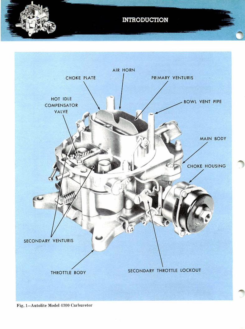
Fig. I - Autoli te Model 4300 Carburetor
AIR HORN
PRIMARY VENTURIS
BODY
SECONDARY THROTTLE LOCKOUT

The Autolite Model 4300 (Fig. 1) is a fou rventuri (barrel) carburetor that operates in t wo stages. The two primary barrels provide fuel-air mixt ures for most operating conditions. Two secondary venturis are timed to furnish additional fuelair mixtures when the primary throttles are threequarters open.
DESIGN CHARACTERISTICS This carburetor design was adopted with the fol
lowing objectives in mind :
• Adaptability to quali ty product ion. • Acceptable hot fuel handling, hot restar ts, and
idle stability. • Improved cornering performance. • Reduced effect of dirty air cleaners on fuel
economy. • Compatibility with exhaust emission control
systems. • Improved choke operation.
Mounting and air cleaner Aange dimensions are the same as on previous Ford four-venturi carburetors. When the Model 4300 is mounted on existing four-venturi intake manifolds, t he throttle bores will be on the same centers .
CARBURETOR SYSTEMS A single fuel inlet system serves both the primary
and secondary venturis. The system has one bowl
CLEAN AIR CLEANER
DIRTY A IR CLEANE R
Fig. 2- Balanced Carburetor
and a dual-pontoon fl oat to cont rol t he fuel level through a conventional inlet valve (needle-and-seat) . An auxilia ry inlet valve also is provided to assist fi lling th e bowl when t he carburetor is handling hot vapors and for maximum engine demands.
Each of the t wo primary barrels has its own idle system and main metering system. The accelerating pump is a piston type, and discharges fuel into the primary venturis when t he t hrottle is opened.
One valve-t ype power fuel supply system provides added fu el to t he main vent uris when t he engine operates under a load.
The automatic choke system serves the primary vent uris only and prevent s t he secondaries fro;n operating when t he engine is cold. Exhaust manifold-heated ai1· is directed t o t he thermosta tic spring which controls the choke pla t e posit ion. The choke pulldown device is a vacuum-oper ated piston in t he choke housing.
Spring-loaded, offset air valves are incorporated in the secondary main metering· sys tems to control air and fuel deliver y to the secondary bar rels . The secondar y t lwott le plates a re linked mechanically to the primary t hrottle linkage through an overtravel spring. The spring permits the primary throttles to open fully when t he choke linkage has the secondari es "locked out ."
A balanced vent system is used; that is, t he bowl is always vented t o the air horn so t hat pressure drop through the air cleaner doesn't upset t he calibration of t he fuel supply systems (Fig. 2) . An additional vent is provided t o vent t he bowl to t he a tmosphe1·e at idle 01· ve1·y low-r pm operation . . . when vaporization is likeliest t o occur in the bowl.
Another special f eature of the Model 4300 is a hot idle compensator system. The compensator is thermostatically oper ated to add air t o t he idle mixture when t he carburetor inlet t emperature is high.
CONSTRUCTION The carburetor is built in three main assemblies
the upper body or air horn ; the main body ; and the lower t h rottle body.
In t he air horn are contained the accelerating pump linkage, the fuel inlet valves and Aoat, t he power valve piston and spring, t he choke plate, the booster venturis, t he secondary bar r el a ii· valves and the hot idle compensator valve.
The main body contains the main meter ing jets, the accelerat ing pump piston, well , discharge valve, the power valve, fu el passages for the various systems and the id le a ir adj ustment screw.
The throttle body contains the throttle plates and linkage, the id le f uel adj ustment needles and the automatic choke assembly.
1

HANDBOOK SCOPE In the sections that follow, we shall discuss the
operation of each of the systems in the 4300 Carburetor, and then go through diagnosis, adjustments and overhaul. Basic carburetor principles will not be covered; that information is in your training handbook entitled "How the Fuel System Operates" - Course 9500.1, and can be reviewed if you happen to be "rusty" on carburetor operation. This handbook will give you the complete story of the Model 4300 Carburetor, building on your basic fuel system knowledge.
Definitions of technical terms appear at the end of the book.
OPERATION The Model 4300 Carburetor is designed to supply
a calibrat ed fuel-air mixture to a V-8 engine. In normal operation, each of the primary ventur is supplies all the fuel,air mixture r equired by four cylinders. The idle, main metering, power fuel supply, accelerating pump and choke systems go into operation automatically to provide the proper richness or leanness of the mixture for the operating condition.
Operation of the fuel metering systems is controlled by the accelerator linkage, throttle position and engine speed. The choke system, of course, is controlled by the throttle position and the temperature of the engine exhaust manifold.
While there is interaction between the various carburetor systems, operation is best understood by considering the systems individually. Let us, then, look at the operation of each system, beginning at where the fuel enters the carburetor.
FUEL INLET SYSTEM Correct calibration of any carburetor depends on
fuel being available at a specific level in the fuel bowl. If the fuel level is low, the metering systems deliver lean mixtures; if the level is high, mixtures are rich. The function of the fuel inlet system is to admit gasoline into the fuel bowl and maintain the specified level.
Figure 3 shows the construction and operation of the fuel inlet system. The fuel inlet is constantly charged with fuel under pressure from the fuel pump. This fuel enters the bowl through the fuel inlet valve, which is permitted to open when the float lowers.
The float moves up-and-down with the fuel level. When enough fuel has entered to fill the bowl to the correct level, the float is high enough for the float lever to push the inlet valve (needle) against
2
0 AIR
FUEL
Fig. 3- Fuel Inlet System
FLOAT
its seat. Flow of the fuel into the bowl then is blocked until some fuel is used and the float lowers again.
Auxiliary Fuel Inlet Valve An auxiliary fuel inlet valve is built into this
system to supplement the main or primary fuel inlet valve when engine fuel requirement s are high.
The main or primary fuel inlet valve controls small fuel flows precisely because of its small area of opening and relatively high valve-to-seat sealing pressure. When large fuel flows are required, as in h igh engine speeds and heavy-load conditions, the fuel level and float height drOJ?, thereby opening the auxiliary valve (Fig. 4) in addit ion to the main or primary fuel inlet valve. The total combined fuel valve opening is larger than the previous single valve that has been used in former Ford carburetors.
In addition to supplying fuel for high engine load conditions, the large combined valve opening also purges the carburetor-to-fuel pump line, after a hot restart, of fuel vapor that forms during a hot soak condition.
Venting the Bowl Two stand pipes beside the air horn (Fig. 3)
vent t he bowl to the fresh air inlet. The stand pipes

D AIR
• FUEL
Fig. 4- Auxiliary Fuel Valve Operation
SPECIF IED
FLOAT DROPS
l
are open to the carburetor intake air after the air passes through the air cleaner. Thus, the bowl pressure and air horn pressure are equal during main metering system operation, and the calibration of the carburetor isn't affected by the air cleaner's condition.
An external vent valve (Fig. 5) is opened by a lever actuated by the accelerating pump linkage when the throttle is closed, or nearly closed. This
Fig. 5- External Vent Valve
valve provides relief during periods of idle and part t hrottle operation when vapor is likely to form in the bowl.
IDLE FUEL SUPPLY SYSTEM When the throttles are closed or nearly closed,
there is not enough air flow through the venturis to create the vacuum needed to operate the primary main metering system. Therefore, we have a separate fuel metering system for idle operation.
The primary idle fuel supply system (Fig. 6) uses the pressure difference between manifold vacuum and atmospheric pressure in the bowl to cause fuel flow. Idle system fuel flow is from the bowl, t hrough the main metering jets and into the main wells. From there, the fuel flows up through calibrated restrictions in the idle t ubes, t hen down the idle channels to the idle cavities in the throttle body. It enters the venturis below the throttle plates through the idle discharge port and idle transfer slot. The idle fuel adjustment screw regulates the amount of fuel that is discharged through the port.
HIGH-SPEED AIR BLEED IDLE AIR BLEED
IDLE FUEL ADJUSTMENT SCREW
Fig. 6-ldle Fuel Supply System
Air Bleeds
D AI R
Ill FUEL rn FUEL AND AIR
D VACUUM
Filtered air is mixed with the fuel t hrough t he idle air bleeds to help the fuel atomize as it is discharged. The bleed also prevents siphoning through the idle system at very high speeds, or when the engine is shut down.
Idle Transl er Slot The idle transfer slot in each venturi serves both
as an air bleed and as a secondary discharge port. At closed throttle (Fig. 7), the top of the slot
3

admits air into the idle cavity, and the bottom of the slot delivers fuel to the venturi. When the throttle opens slightly above an idle condition, the whole length of the slot becomes a discharge port to richen the mixture (Fig. 7). This secondary discharge opening prevents the increase in air flow from making the mixture too lean. There would be a "flat spot" in the transition from the idle to the main metering system without the transfer slot.
D AIR
• FUEL
PORT
(I] FUEL AND AIR
D VACUUM
Fig. 7-ldle Transfer Slot is Secondary Discharge Passage
Idle Air Bypass System The idle air bypass system (Fig. 6) is incorporated
in the idle system. This provides a precise way of adjusting idle rpm by admitting more or less air to the mixture after it is discha1·ged into the barrel. Filtered air enters this system through a pick-up hole near the base of the main venturi. The air passes the idle air adjustment scr ew down into the thrott le body; then, is discharged below the t hrottle plate.
Opening the idle air adjustment screw leans the mixture and incr eases engine rpm. The idle fuel adjustment screws-one for each idle system-permit adding more fuel if needed for a smooth idle.
PRIMARY MAIN FUEL METERING SYSTEMS
A primary main fuel metering system, divided into two parts ... one for each primary barrel ...
4
provides t he fuel required by the engine at cruising speeds. Main metering systems are calibrated to deliver a lean mixture ... about 15 parts air to one part gasoline .. . when the engine is loafing along. When more power is required, the main metering system continues to operate, and the mixture is made richer by other systems.
Parts of the Main Metering System In t he Model 4300 carburetor, t he primary main
metering system (Fig. 8) has two main metering jets;. main wells, and main well t ubes; calibrated air bleeds; discharge nozzles; and booster venturis. At rest, fuel flows from the bowl, t hrough the main jets, and into the main wells and tubes. In each well and tube, the fuel assumes the same level as in the bowl until the engine begins to operate.
Pressure Difference Causes Flow Wit h the engine operating, the main meter ing
system delivers fuel in response to t he throttle plate opening. Opening the t hrottle causes air flow thr ough the main venturi and booster venturi ; the flow through the booster venturi causes a pressure drop or partial vacuum at the discharge nozzle. The fuel bowl is at air horn pressure, so we have a pressure difference that creates flow through the system. Fuel is sprayed out the discharge nozzle and mixes with the airstream.
D AIR
• FUEL
[I FUEL AND AIR
D VACUUM
MAIN METERING JET
BOOSTER VENTURI
MAIN WELL TUBE
Fig. 8- Primary Main Metering System
The size of the main j et determines how much fuel is delivered for a given volume of air flow. Increasing or decreasing throttle opening increases or

decreases the fuel delivery so that the mixtur e proportion or ratio is quite constant.
Bleed Assists Vaporization The high-speed air bleed (Fig. 9) in the system
permits some air to be mixed with the fuel in the main well. The air enters the main well tube through two holes when fuel is flowing in the system. Adding air at this point assists vaporization, and compensates for the tendency of the air to become less dense at high speeds. The bleed also doubles as an anti-siphoning vent at low speeds. And it discourages percolation when a hot engine is shut down by venting the main well.
Fig. 9- High-Speed Air Bleeds
ACCELERATING PUMP SYSTEM Air, being very light, responds rapidly to changes
in the throttle opening. Gasoline is heavier, and therefore not as responsive. When the throttles are opened suddenly, air flow increases rapidly, but fuel flow lags. So that the engine will respond instantly to opening the throttle, we have an accelerating pump system, which furnishes a single spur t of fuel in each primary venturi when the throttles are opened.
Piston-Type Pump A piston-type pump (Fig. 10) is actuated by a link
from the accelerator linkage and by a spring to cause the pumping action. The pumping chamber is formed below a cup on the pump piston. A ball-type intake check valve and a needle-type discharge valve control the flow of fuel into and out of the pumping chamber and channels. Discharge nozzles open into both primary venturis.
Fuel Intake Fuel intake occurs as the throttles are closed (Fig.
10). The accelerating pump link pulls the piston up, compressing the piston spring. A partial vacuum
PARTIAL
D AIR
• FUEL
VACUUM INTAKE CHECK VALVE (UNSEATED)
Fig. 10- Accelerating Pump System-Intake
or void is created below the piston cup in the pumping chamber.
Fuel in the bowl, at this time, is exposed to full atmospheric pressur e, as the external vent valve lever also is actuated by the accelerating pump link to open the valve.
The pressure difference pushes the intake check valve off its seat and causes fuel to flow from the bowl into the pumping chamber. The discharge valve is seated, and prevents backftow in the discharge passages.
Fuel Discharge When the throttles open (Fig. 11), the end of the
accelerating pump link moves down in the piston arm slot, and the spring pushes the piston into the pumping chamber. Pressure builds up in the chamber to force the inlet valve closed on its seat.
Fuel is pumped through the discharge passages ... the discharge valve is forced open by the fuel pressure ... and fuel is sprayed out the discharge nozzle. When the piston has reached its limit of travel (depending on how far the accelerator is depressed), flow stops and the discharge valve seats. The discharge passages remain primed, or full of fuel, so that pumping action t hrough the nozzles is instantaneous on the next cycle.
Air Bleed Check Valve With the engine operating at high speed, a
vacuum exists at the accelerating pump discharge
5

OUT LET CHAN N EL CLOSED
Fig. 11-Accelerating Pump - Discharge
. FUEL
nozzles. An air bleed check valve prevents this vacuum from siphoning fuel through the accelerating pump system when fuel is not being dischar ged. The valve is placed at the upper end of the discharge nozzle passage.
POWER FUEL SUPPLY SYSTEM
We have said t hat t he main metering system provides a lean mixture for cruising conditions, when power requir ements are not h igh. When more power is required .. . for high-speed operation or for ac-celerating .. . we have to burn more fuel. The small amount of fuel in a lean mixture doesn't provide enough heat upon combustion for full engine power . Therefore, we provide a way to "step up" or richen the mixture . . . we call this "step up" system the power fuel supply system (Fig. 12).
Vacuum Piston and Power Valve The power fuel supply system uses a vacuum
controlled piston in t he air horn body and a power valve to admit more fuel when power is required. The vacuum piston rod is spring-loaded and tends to push t he rod down. The stem of t he power valve also is spring-loaded, tending to hold the power valve up or closed.
Manifold vacuum is sensed on top of the piston t hrough passages in the carburetor bodies. At idle or cruising conditions, the vacuum is high enough to overcome the piston rod spring force. The piston and rod are held up and away from the power valve stern. The power valve spring then holds the valve closed.
6
VACUUM PISTON
SPR INGS
POWER VALVE
• FUEL
O vACUUM POWER JET
Fig. 12-Power Fuel Supply System
Another Passage to the Main Well
When the engine is under load, the vacuum drops. The vacuum piston r od is pushed down by its spring and t he rod pushes on t he power valve stem. The comparatively light power valve spring is overcome, and the valve opens (Fig. 13). Opening t he valve gives us another passage from the bowl to t he main wells . . . th rough the valve and power jets. The effect is the same as if we temporarily increased
MAIN WELL
D AIR
II FUEL
D VACUUM
VALVE OPENS
Fig. 13- Power Valve Action


9 503.1 and 2-1
DESCRIPTION
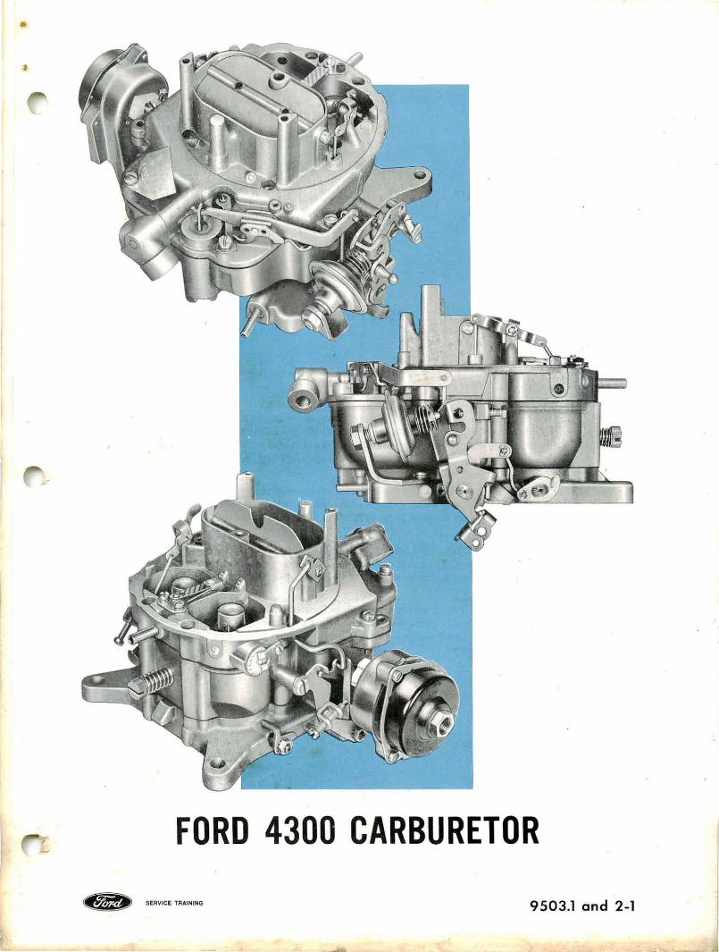
The Ford 4300 model carburetor is a four-venturi type. It has three main assemblies; the air horn, the main body and the throttle body.
The main sub - assemblies contained in the air horn casting are: the accelerating pump piston, return spring and operating link; the fuel inlet needle, seat and float; the secondary air throttle plates and torsion spring; the choke plate; the hot idle compensator valve; the linkage and piston for the secondary air throttle damper, the primary and secondary booster venturis and the vacuum piston and spring for the power valve.
Under the air horn assembly is the main body. It contains the main metering jets, the power valve, the idle system air adjusting screw, the accelerating pump discharge needle, and fuel passages for the various systems.
Beneath the main body is the throttle body. Contained in the throttle body are the primary and secondary throttle plate.s and linkage, the idle fuel adjusting needles, and the automatic choke housing, bimetal spring and pulldown piston.
This carburetor design was adopted with the following objectives in mind:
• Adaptibility to quality production.
• Acceptable hot fuel handling, hot restarts, and idle stability.
• Improved cornering performance.
• Reduced effect of dirty air cleaners on fuel economy.
• Compatibility with exhaust emission control systems.
• Improved choke operation.
The 4300 model carburetor will mount on the existing four-venturi intake manifolds with the throttle bores being on the same centers as previous Ford four-venturi carburetors.
Mounting height and air cleaner flange diameter has been maintained the same as on past models.
'
--
FORD 4300 CARBURETOR
~ SERVICE TRAINING 9503.l and 2-1
9503.l and 2-2
OPERATION
FUEL INLET SYSTEM
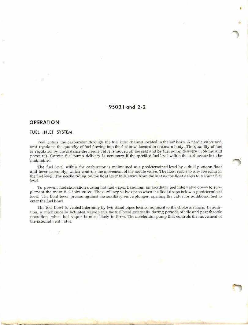
Fuel enters the carburetor through the fuel inlet channel located in the air horn. A needle v alve and seat regulates the quantity of fuel flowing into the fuel bowl located in the main body. The quantity of fuel is regulated by the ·distance the needle valve is moved off the seat and by fuel pump delivery (volume and pressure). Correct fuel pump delivery is necessary if the specified fuel level within the carburetor is to be maintained.
The fuel level within the carburetor is maintained at a predetermined level by a dual pontoon float and lever assembly, which controls the movement of the needle valve. The float reacts to any lowering in the fuel level. The needle riding on the float lever falls away from the seat as the float drops to a lower fuel level.
To prevent fuel starvation during hot fuel vapor handling, an auxiliary fuel inlet valve opens to supplement the main fuel inlet valve. The auxiliary valve opens when the float drop_s below a predetermined level. The float lever presses against the a uxiliary valve plunger, opening the valve for additional fuel to enter the fuel bowl.
The fuel bowl is vented internally by two stand pipes located adjacent to the choke air horn. In addition, a mechanically actuated valve vents the fuel bowl externally during periods of idle and part throttle operation, when fuel vapor is most likely to form. The accelerator pump link contr ols the movement of the external vent valve.
•

AUXILIARY VALVE AND SEAT
~ SERVICE TRAINING
INTERNAL BOWL VENT -----i
FUEL INLET VALY.E AND SEAT
CJ AIR CJ FUEL
FUEL INLET SYSTEM
9503.l and 2- 2

9503.1 and 2-3
OPERATION - Continued
IDLE SYSTEM
Idle Fuel
The primary idle fuel system functions when the engine is operating at low engine rpm. It supplies the fuel- air mixture when the air flow past the carburetor venturi is insufficient to operate the main metering system. Air bleeds, restrictors and adjustments are provided to control and meter the idle fuel - air mixture.
At curb idle speeds, the throttle plates are completely closed and with manifold vacuum below the plates, enough difference in pressure is created between the fuel bowl and the idle discharge por ts to operate the idle fuel system.
Fuel is forced from the fuel bowl through the main metering jets and into the main well. The fuel then flows up through a calibrated restriction in the idle tube. Filtered air enters an idle air bleed restriction and mixes with the fuel flowing up the idle tube. The idle air bleed also serves as an anti- syphoning vent at high engine speeds or when the engine is shut down. The fuel - air mixture passes down the idle channel into an idle cavity in the throttle body. The idle cavity has an upper and lower discharge port. At curb idle (throttle plate closed), the idle fuel- air mixture flows past an idle fuel adjusting screw and is dis charged below the throttle plate from the lower discharge port and from a small portion of the upper discharge port.
The upper discharge port is a vertical slot- type port and extends slightly b elow the closed throttle plate. When opening the throttle plate, a greater portion of the upper discharge port is exposed to mani fold vacuum and a larger amount of idle fuel- air mixture will discharge from the upper port. Further opening of the throttle plate results in a decrease in manifold vacuum and a decrease in the quantity of idle fuel- air mixture that is discharged. As the idle system tapers off, the main fuel metering system begins to discharge fuel.
Idle Air Bypass
The idle sp eed (engine rpm) is adjusted by turning an idle air adjusting screw to admit m ore or less air, as required, below the throttle plates. This method of a ir control bypasses the throttle plates. Filtered air enters through a pickup hole located near the base of the main venturi. The air passes by the idle air adjusting screw and down into the throttle body. The air is then discharged from a port below the throttle plate.
It is particularly important that the idle air and the idle fuel mixture adjustments are performed at the same time. Opening the idle air screw to increase engine rpm leans the fuel- aix mixture, consequently, the idle fuel mixture must also b e increased to provide the proper fuel - air mixture for smooth engine idle.


