Tranquility ® Compact Belt Drive (TCH/V) Series Submittal Data Models TCH072 - 120 TCV072 - 300 60Hz - HFC-410A English Language/I-P Units ClimateMaster works continually to improve its products. As a result, the design and specifications of each product at the time of order may be changed without notice and may not be as described herein. Please contact ClimateMaster's Customer Service Department at 1-405-745-6000 for specific information on the current design and specifications. Statements and other information contained herein are not express warranties and do not form the basis of any bargain between the parties, but are merely ClimateMaster's opinion or commendation of its products. The latest version of this document is available at climatemaster.com. *LC517* LC517 Revised: 06 February, 2013 Revised: 06 February, 2013 SUBMITTAL DATA - I-P UNITS Unit Designation: Job Name: Architect: Engineer: Contractor: PERFORMANCE DATA Cooling Capacity: Btuh EER: Heating Capacity: Btuh COP: Ambient Air Temp: °F Entering Water Temp (Clg): °F Entering Air Temp (Clg): °F Entering Water Temp (Htg): °F Entering Air Temp (Htg): °F Airflow: CFM Fan Speed or Motor/RPM/Turns: Operating Weight: (lb) ELECTRICAL DATA Power Supply: Volts Phase Hz Minimum Circuit Ampacity: Maximum Overcurrent Protection:
Transcript
Tranquility® Compact
Belt Drive (TCH/V) Series
Submittal Data
Models TCH072 - 120 TCV072 - 300
60Hz - HFC-410A
English Language/I-P Units
ClimateMaster works continually to improve its products. As a result, the design and specifi cations of each product at the time of order may be changed without notice and may not be as described herein. Please contact ClimateMaster's Customer Service Department at 1-405-745-6000 for specifi c information on the current design and specifi cations. Statements and other information contained herein are not express warranties and do not form the basis of any bargain between the parties, but are merely ClimateMaster's opinion or commendation of its products. The latest version of this document is available at climatemaster.com.
*LC517* LC517 Revised: 06 February, 2013
Revised: 06 February, 2013
SUBMITTAL DATA - I-P UNITS
Unit Designation:
Job Name:
Architect:
Engineer:
Contractor:
PERFORMANCE DATA
Cooling Capacity: Btuh
EER:
Heating Capacity: Btuh
COP:
Ambient Air Temp: °F
Entering Water Temp (Clg): °F
Entering Air Temp (Clg): °F
Entering Water Temp (Htg): °F
Entering Air Temp (Htg): °F
Airfl ow: CFM
Fan Speed or Motor/RPM/Turns:
Operating Weight: (lb)
ELECTRICAL DATA
Power Supply: Volts
Phase Hz
Minimum Circuit Ampacity:
Maximum Overcurrent Protection:
Tranquility® Compact
Belt Drive (TCH/V) Series
Submittal Data
Models TCH072 - 120 TCV072 - 300
60Hz - HFC-410A
English Language/S-I Units
ClimateMaster works continually to improve its products. As a result, the design and specifi cations of each product at the time of order may be changed without notice and may not be as described herein. Please contact ClimateMaster's Customer Service Department at 1-405-745-6000 for specifi c information on the current design and specifi cations. Statements and other information contained herein are not express warranties and do not form the basis of any bargain between the parties, but are merely ClimateMaster's opinion or commendation of its products. The latest version of this document is available at climatemaster.com.
*LC517* LC517 Revised: 06 February, 2013
Revised: 06 February, 2013
SUBMITTAL DATA - S-I UNITS
Unit Designation:
Job Name:
Architect:
Engineer:
Contractor:
PERFORMANCE DATA
Cooling Capacity: kW
EER:
Heating Capacity: kW
COP:
Ambient Air Temp: °C
Entering Water Temp (Clg): °C
Entering Air Temp (Clg): °C
Entering Water Temp (Htg): °C
Entering Air Temp (Htg): °C
Airfl ow: l/s
Fan Speed or Motor/RPM/Turns:
Operating Weight: (kg)
ELECTRICAL DATA
Power Supply: Volts
Phase Hz
Minimum Circuit Ampacity:
Maximum Overcurrent Protection:
ClimateMaster works continually to improve its products. As a result, the design and specifi cations of each product at the time of order may be changed without notice and may not be as described herein. Please contact ClimateMaster's Customer Service Department at 1-405-745-6000 for specifi c information on the current design and specifi cations. Statements and other information contained herein are not express warranties and do not form the basis of any bargain between the parties, but are merely ClimateMaster's opinion or commendation of its products. The latest version of this document is available at climatemaster.com.
Page ______ of ______Revised: 06 February, 2013LC517 - 3
Tranquility® Compact Belt Drive (TCH/V) Series Submittal Data Eng/I-P
Table of Contents
*Document page number is shown next to part number (e.g. LC517 - 3 = page 3). Since not all pages are typically used in the submittals process, the page number in the lower right corner can still be used (page ____of_____).
ClimateMaster works continually to improve its products. As a result, the design and specifi cations of each product at the time of order may be changed without notice and may not be as described herein. Please contact ClimateMaster's Customer Service Department at 1-405-745-6000 for specifi c information on the current design and specifi cations. Statements and other information contained herein are not express warranties and do not form the basis of any bargain between the parties, but are merely ClimateMaster's opinion or commendation of its products. The latest version of this document is available at climatemaster.com.
Page ______ of ______Revised: 06 February, 2013LC517 - 4
Tranquility® Compact Belt Drive (TCH/V) Series Submittal Data Eng/I-P
THE TRANQUILITY® TCH/V (BELT DRIVE) SERIES
The award winning Tranquility® Series raises the bar for water-source heat pump effi ciencies, features and application fl exibility. Not only does the Tranquility® TC exceed ASHRAE 90.1 effi ciencies, but it also uses EarthPure® HFC-410A zero ozone depletion refrigerant, making it an extremely environmentally-friendly option. Tranquility® TC is eligible for additional LEED (Leadership in Energy and Environmental Design) points because of the “green” technology design.
Available in sizes 6 tons (21.1 kW) through 25 tons (87.9 kW) with multiple cabinet confi gurations, the Tranquility® (TCH/V) Series offers a wide range of units for most any installation. The Tranquility® Series has an extended range refrigerant circuit, capable of ground loop (geothermal) applications (may require optional extended range insulation), ground water (geothermal) applications, as well as water loop (boiler-tower) applications. Standard features are many. Microprocessor controls, galvanized steel cabinet, epoxy powder coat painted front access panel, galvanized steel with epoxy powder coat painted drain pan and TXV refrigerant metering device are just some of the features of the fl exible Tranquility® Series.
ClimateMaster’s exclusive double isolation compressor mounting system makes the Tranquility® TCH/V one of the quietest units on the market. Compressors are mounted on specially engineered sound-tested EPDM grommets to a heavy gauge mounting plate, which is further isolated from the cabinet base with rubber grommets for maximized vibration and sound attenuation. The easy access control box and large access panels make installing and maintaining the unit easier than other water-source heat pumps currently in production.
Options such as coated air coil, DDC controls, and dual point power allow customized design solutions. Optional blower motor/sheave drive packages expand the operating range and help overcome some of the challenges associated with ductwork for retrofi t installations. A cupro-nickel water-coil and sound absorbing UltraQuiet package are options that make a great unit even better.
The Tranquility® TCH/V Series Water-Source Heat Pumps are designed to meet the challenges of today’s HVAC demands with one of the most innovative products available on the market.
• Horizontal unit confi guration can be ordered with left or right return air and straight or back supply air discharge. Discharge is fi eld convertible. Field conversion uses all existing parts including panels and belts
• Vertical confi guration can be ordered with front or back return and top, front, or back discharge.
• Electrical box is on right side and can be fi eld converted to left side of unit
• Electric power can enter from either side of front• Water can be connected to either side• Copeland scroll compressors• Dual refrigeration circuits (All Models)• Exceeds ASHRAE 90.1 effi ciencies• Galvanized steel construction with attractive matte
black epoxy powder coat painted front access panel• Insulated divider and separate compressor/air
handler compartments• TXV metering device • Extended range 20 to 120°F (-6.7 to 48.9°C) operation
(may require optional extended range insulation)• Hanger brackets standard for horizontal units• Premium duty motor that is VFD compatible
AVAILABLE OPTIONS
• Blower motor/sheave drive packages• LonWorks, BACnet, Modbus and Johnson N2
compatibility options for DDC controls• Cupro-nickel water-coil• Sound absorbing UltraQuiet package• Coated air coil• Dual point power
Unit Features
ClimateMaster works continually to improve its products. As a result, the design and specifi cations of each product at the time of order may be changed without notice and may not be as described herein. Please contact ClimateMaster's Customer Service Department at 1-405-745-6000 for specifi c information on the current design and specifi cations. Statements and other information contained herein are not express warranties and do not form the basis of any bargain between the parties, but are merely ClimateMaster's opinion or commendation of its products. The latest version of this document is available at climatemaster.com.
Page ______ of ______Revised: 06 February, 2013LC517 - 5
Tranquility® Compact Belt Drive (TCH/V) Series Submittal Data Eng/I-P
LWT = EWT -HE
GPM x 500
LAT = EAT +HC
CFM x1.08
LWT = EWT +HR
GPM x 500
LAT (DB) = EAT (DB) - SCCFM x1.08
LC = TC - SC
S/T =SCTC
Heating Cooling
Air Flow Water Flow Ext Static Pressure Water Pressure Drop
Airflow (L/s) = CFM x 0.472 Water Flow (L/s) = gpm x 0.0631 ESP (Pa) = ESP (in of wg) x 249 PD (kPa) = PD (ft of hd) x 2.99
Reference Calculations
BTUH = BTU( British Thermal Unit) per hour CFM = airfl ow, cubic feet/minute COP = coeffi cient of performance = BTUH output/BTUH input DB = dry bulb temperature (°F) EAT = entering air temperature, Fahrenheit (dry bulb/wet bulb) EER = energy effi ciency ratio = BTUH output/Watt input MPT = male pipe thread ESP = external static pressure (inches w.g.) EWT = entering water temperature GPM = water fl ow in U.S. gallons/minute HE = total heat of extraction, BTUH HC = air heating capacity, BTUH HR = total heat of rejection, BTUH
HWC = hot water generator (desuperheater) capacity, Mbtuh FPT = female pipe thread KW = total power unit input, kilowatts LAT = leaving air temperature, °F LC = latent cooling capacity, BTUH LWT = leaving water temperature, °FMBTUH = 1000 BTU per hour S/T = sensible to total cooling ratio SC = sensible cooling capacity, BTUH TC = total cooling capacity, BTUH WB = wet bulb temperature (°F) WPD = waterside pressure drop (psi & ft. of hd.)
Conversion Table - to convert inch-pound (English) to S-I (Metric)
Legend and Glossary of Abbreviations
Selection Procedure
ClimateMaster works continually to improve its products. As a result, the design and specifi cations of each product at the time of order may be changed without notice and may not be as described herein. Please contact ClimateMaster's Customer Service Department at 1-405-745-6000 for specifi c information on the current design and specifi cations. Statements and other information contained herein are not express warranties and do not form the basis of any bargain between the parties, but are merely ClimateMaster's opinion or commendation of its products. The latest version of this document is available at climatemaster.com.
Page ______ of ______Revised: 06 February, 2013LC517 - 6
Tranquility® Compact Belt Drive (TCH/V) Series Submittal Data Eng/I-P
Step 1 Determine the actual heating and cooling loads at the desired dry bulb and wet bulb conditions.
Step 2 Obtain the following de sign parameters: Entering water temperature, water fl ow rate in GPM, air fl ow in CFM, water fl ow pressure drop and design wet and dry bulb temperatures. Air fl ow CFM should be between 300 and 450 CFM per ton. Unit water pressure drop should be kept as close as possible to each other to make water balancing easier. Go to the ap pro pri ate tables and fi nd the proper indicated water fl ow and water tem per a ture.
Step 3 Select a unit based on total and sensible cooling conditions. Select a unit which is closest to the actual cooling load.
Step 4 Use data from performance tables at the design water fl ow and water temperature. Read the total and sensible cooling capacities (Note: interpolation is per mis si ble, ex trap o la tion is not).
Step 5 Read the heating capacity. If it exceeds the design criteria it is acceptable. It is quite normal for Water-Source Heat Pumps to be selected on cooling capacity only since the heating output is usually greater than the cooling capacity.
Step 6 Determine the correction factors associated with the variable factors of dry bulb and wet bulb (page 14).
Corrected Total Cooling = tabulated total cooling x wet bulb correction. Corrected Sensible Cooling = tabulated sensible cooling x wet/dry bulb correction.
Step 7 Determine the correction factor associated with antifreeze in system loop. If heating EWT is 50°F or below you may have to use antifreeze. Calculate leaving water temperature per performance data selection notes (page 18). If antifreeze is required, use correction table for correcting total and sensible capacities.
Step 8 Compare the corrected capacities to the load re quire ments. Normally if the capacities are within 10% of the loads, the equipment is ac cept able. It is better to undersize than oversize, as undersizing improves humidity control, reduces sound levels and extends the life of the equip ment.
Step 9 When completed, calculate water temperature rise and assess the selection. If the units selected are not within 10% of the load cal cu la tions, then review what effect chang ing the GPM, water temperature and/or air fl ow and air tem per a ture would have on the corrected capacities. If the desired capacity cannot be achieved, select the next larger or smaller unit and repeat the procedure. Remember, when in doubt, undersize slightly for best performance.
Example Equipment Selection For Cool ing
Step 1 Load Determination:
Assume you have determined that the appropriate cooling load at the desired dry bulb 80°F and wet bulb 65°F con di tions is as follows:
Total Cooling.................................................90,500 BTUH Sensible Cooling...........................................73,300 BTUH Entering Air Temp...........80°F Dry Bulb / 65°F Wet Bulb
Step 2 Design Conditions:
Similarly, you have also obtained the following design pa ram e ters:
Entering Water Temp (Cooling).................................90°F Entering Water Temp (Heating).................................60°F Water Flow (Based upon 12°F rise in temp.)......18 GPM Air Flow..............................................................2,800 CFM
Step 3, 4 & 5 HP Selection:
After making your preliminary selection (TCH096), we enter the data from tables at design water fl ow and water tem per a ture and read Total Cooling, Sens. Cooling and Heat of Rej. ca pac i ties:
Total Cooling....................................................93,200 BTUH Sensible Cooling..............................................70,390 BTUH Heat of Rejection...........................................120,100 BTUH Airfl ow...................................................................3,200 CFM
Table Ent Air Air Flow Cor rect ed Corrected Total Cooling = 93,200 x .977 x .976 x 1 = 88,871 Corrected Sens Cooling = 70,390 x 1.088 x .933 x 1=71,453 Corrected Heat of Rej. = 120,100 x .998 x .976 =116,983
Step 9 Water Temperature Rise Calculation & As sess ment:
Rise = Heat of Reject ÷ (GPM x 500)
Actual Temperature Rise 116,983 ÷ 9,000 = 13.0°F
When we compare the Corrected Total Cooling and Corrected Sensible Cooling fi gures with our load re quire ments stated in Step 1, we discover that our selection is within +/- 10% of our sensible load requirement. Fur ther more, we see that our Cor rect ed Total Cooling fi gure is slightly undersized as recommended, when compared to the actual in di cat ed load.
Alternate Step 7: If your EWT for heating is 40°F then system requires antifreeze. If a solution of 15% Propylene Glycol is required, then:
Corrected Total Cooling = 88,871 x .986 = 87,626 Corrected Sens Cooling = 71,453 x .986 = 70,452
Selection Procedure
ClimateMaster works continually to improve its products. As a result, the design and specifi cations of each product at the time of order may be changed without notice and may not be as described herein. Please contact ClimateMaster's Customer Service Department at 1-405-745-6000 for specifi c information on the current design and specifi cations. Statements and other information contained herein are not express warranties and do not form the basis of any bargain between the parties, but are merely ClimateMaster's opinion or commendation of its products. The latest version of this document is available at climatemaster.com.
Page ______ of ______Revised: 06 February, 2013LC517 - 7
Tranquility® Compact Belt Drive (TCH/V) Series Submittal Data Eng/I-P
TCH/V Series Nomenclature
TC H A0 9 6 CH 3 A A L S S1 2 3 4 5 6 7 8 9 10 11 12 13 14 15
LS = LEFT RETURN/STRAIGHT DISCHARGERB = RIGHT RETURN/BACK DISCHARGE
S = STANDARD
N = Cupro-Nickel Water Coil w/Non-Coated Air Coil
RS = RIGHT RETURN/STRAIGHT DISCHARGEVB = LEFT RETURN S.S. DRAIN PAN/BACK DISCHARGEVS = LEFT RETURN S.S. DRAIN PAN/STRAIGHT DISCHARGE
ETL ApprovedUSA & Canada
A = STANDARD RPM & STANDARD MOTORB = LOW RPM & STANDARD MOTORC = HIGH RPM & STANDARD MOTORD = STANDARD RPM & LARGE MOTORE = HIGH RPM & LARGE MOTOR
WB = RIGHT RETURN S.S. DRAIN PAN/BACK DISCHARGEWS = RIGHT RETURN S.S. DRAIN PAN/STRAIGHT DISCHARGE
A = DUAL POINT POWER
V = VERTICAL
TCHONLY
BF = BACK RETURN/FRONT DISCHARGEBT= BACK RETURN/TOP DISCHARGEFB = FRONT RETURN/BACK DISCHARGEFT = FRONT RETURN/TOP DISCHARGEYF = BACK RETURN S.S. DRAIN PAN/FRONT DISCHARGEYT = BACK RETURN S.S. DRAIN PAN/TOP DISCHARGEZB = FRONT RETURN S.S. DRAIN PAN/BACK DISCHARGEZT = FRONT RETURN S.S. DRAIN PAN/TOP DISCHARGE
TCVONLY
A = Copper Water Coil w/Coated Air Coil
J = Cupro-Nickel Water Coil w/Coated Air Coil
160192240300
CABINET INSULATION / FILTER RAILS/FRAMES
OPTION RANGE 2” FILTERFRAMES
4” FILTERFRAMES
1AB
CD
EF
GH
ULTRA QUIET
TCV TCH
NO
NO
YES
YES
NO NONO
NONO
NONO
NONO
NO
NONO
NO
NO
NO
NO
NO
NO
NO
YESYES
YES
YES
YES
NOYES
YES
YES
YES
YES
YES
YES
YES
YES
YES
YES
1” FILTERFRAMES
1” FILTERRAIL
2” FILTERRAIL
YESNO
YESNO
YESNO
YESNO
NO
NO
NO
NO2
3
4
H = 208-230/60/3 (FACTORY WIRED 208)F = 460/60/3
N = 575/60/3
ClimateMaster works continually to improve its products. As a result, the design and specifi cations of each product at the time of order may be changed without notice and may not be as described herein. Please contact ClimateMaster's Customer Service Department at 1-405-745-6000 for specifi c information on the current design and specifi cations. Statements and other information contained herein are not express warranties and do not form the basis of any bargain between the parties, but are merely ClimateMaster's opinion or commendation of its products. The latest version of this document is available at climatemaster.com.
Page ______ of ______Revised: 06 February, 2013LC517 - 8
Tranquility® Compact Belt Drive (TCH/V) Series Submittal Data Eng/I-P
Performance Data – AHRI/ASHRAE/ISO 13256-1
ASHRAE/AHRI/ISO 13256-1. English (I-P) Units
ASHRAE/AHRI/ISO 13256-1. Metric (S-I) Units
Model
Water Loop Heat Pump Ground Water Heat Pump Ground Loop Heat Pump
Cooling capacities based upon 80.6°F DB, 66.2°F WB entering air temperature.Heating capacities based upon 68°F DB, 59°F WB entering air temperature.All ratings based upon operation at lower voltage of dual voltage rated models.All TCH/V072 ratings @ 2400CFM w/20GPM. Sheave setting for AHRI is 2.5 turns open.All TCH/V096 ratings @ 3200CFM w/24GPM. Sheave setting for AHRI is 3.0 turns open.All TCH/V120 ratings @ 4000CFM w/30GPM. Sheave setting for AHRI is 3.0 turns open.
Cooling capacities based upon 27°C DB, 19°C WB entering air temperature.Heating capacities based upon 20°C DB,15°C WB entering air temperature.All ratings based upon operation at lower voltage of dual voltage rated models.All TCH/V072 ratings @ 1133 l/s w/1.26 l/s. Sheave setting for AHRI is 2.5 turns open.All TCH/V096 ratings @ 1510 l/s w/1.51 l/s. Sheave setting for AHRI is 3.0 turns open.All TCH/V120 ratings @ 1888 l/s w/1.89 l/s. Sheave setting for AHRI is 3.0 turns open.
ClimateMaster works continually to improve its products. As a result, the design and specifi cations of each product at the time of order may be changed without notice and may not be as described herein. Please contact ClimateMaster's Customer Service Department at 1-405-745-6000 for specifi c information on the current design and specifi cations. Statements and other information contained herein are not express warranties and do not form the basis of any bargain between the parties, but are merely ClimateMaster's opinion or commendation of its products. The latest version of this document is available at climatemaster.com.
Page ______ of ______Revised: 06 February, 2013LC517 - 9
Tranquility® Compact Belt Drive (TCH/V) Series Submittal Data Eng/I-P
For operation in the shaded area when water is used in lieu of an antifreeze solution, the LWT (Leaving Water Temperature) must be calculated. Flow must be maintained to a level such that the LWT is maintained above 42°F [5.6°C] when the JW3 jumper is not clipped (see example below). Otherwise, appropriate levels of a proper antifreeze solution should be used in systems with leaving water temperatures of 42ºF [5.6°C] or below and the JW3 jumper should be clipped. This is due to the potential of the refrigerant temperature being as low as 32°F [0°C] with 40°F [4.4°C] LWT, which may lead to a nuisance cutout due to the activation of the Low Temperature Protection. JW3 should never be clipped for standard range equipment or systems without antifreeze.
Example:
At 50°F EWT (Entering Water Temperature) and 1.5 gpm/ton, a 8 ton unit has a HE of 72,200 Btuh.
To calculate LWT, rearrange the formula for HE as follows:
HE = TD x GPM x 500, where HE = Heat of Extraction (Btuh); TD = temperature difference (EWT - LWT) and GPM = U.S. Gallons per Minute.
TD = HE / (GPM x 500)
TD = 72,200 / (12 x 500)
TD = 12°F
LWT = EWT - TD
LWT = 50 - 12 = 38°F - antifreeze must be used
In this example, a higher fl ow rate will be required for EWTs at or below 50°F without antifreeze.
Performance Data – Selection Notes
WATER/BRINE
EWT°F
FLOWgpm
PDpsi
PD ft.
50
12.0 1.7 4.0
18.0 4.5 10.3
24.0 7.9 18.2
TCH/V096Heating - EAT 70°F
HC kW HE LAT COP
96.7 7.17 72.2 95.9 4.0
101.9 7.27 77.1 97.4 4.1
104.7 7.32 79.8 98.2 4.2
ClimateMaster works continually to improve its products. As a result, the design and specifi cations of each product at the time of order may be changed without notice and may not be as described herein. Please contact ClimateMaster's Customer Service Department at 1-405-745-6000 for specifi c information on the current design and specifi cations. Statements and other information contained herein are not express warranties and do not form the basis of any bargain between the parties, but are merely ClimateMaster's opinion or commendation of its products. The latest version of this document is available at climatemaster.com.
Page ______ of ______Revised: 06 February, 2013LC517 - 10
Tranquility® Compact Belt Drive (TCH/V) Series Submittal Data Eng/I-P
Performance Data – TCH/V072
Performance capacities shown in thousands of Btuh2,400 CFM Nominal Airfl ow Heating & Cooling
Interpolation is permissible; extrapolation is not.All entering air conditions are 80°F DB and 67°F WB in cooling, and 70°F DB in heating. AHRI/ISO certifi ed conditions are 80.6°F DB and 66.2°F WB in cooling and 68°F DB in heating. Table does not refl ect fan or pump power corrections for AHRI/ISO conditions.All performance is based upon the lower voltage of dual voltage rated units.Performance stated is at the rated power supply; performance may vary as the power supply varies from the rated.Operation below 40°F EWT is based upon a 15% methanol antifreeze solution. Operation below 60°F EWT requires optional insulated water/refrigerant circuit.See performance correction tables for operating conditions other than those listed above.See Performance Data Selection Notes for operation in the shaded areas.
ClimateMaster works continually to improve its products. As a result, the design and specifi cations of each product at the time of order may be changed without notice and may not be as described herein. Please contact ClimateMaster's Customer Service Department at 1-405-745-6000 for specifi c information on the current design and specifi cations. Statements and other information contained herein are not express warranties and do not form the basis of any bargain between the parties, but are merely ClimateMaster's opinion or commendation of its products. The latest version of this document is available at climatemaster.com.
Page ______ of ______Revised: 06 February, 2013LC517 - 11
Tranquility® Compact Belt Drive (TCH/V) Series Submittal Data Eng/I-P
Performance Data – TCH/V096
Performance capacities shown in thousands of Btuh3,200 CFM Nominal Airfl ow Heating & Cooling
Interpolation is permissible; extrapolation is not.All entering air conditions are 80°F DB and 67°F WB in cooling, and 70°F DB in heating. AHRI/ISO certifi ed conditions are 80.6°F DB and 66.2°F WB in cooling and 68°F DB in heating. Table does not refl ect fan or pump power corrections for AHRI/ISO conditions.All performance is based upon the lower voltage of dual voltage rated units.Performance stated is at the rated power supply; performance may vary as the power supply varies from the rated.Operation below 40°F EWT is based upon a 15% methanol antifreeze solution. Operation below 60°F EWT requires optional insulated water/refrigerant circuit.See performance correction tables for operating conditions other than those listed above.See Performance Data Selection Notes for operation in the shaded areas.
ClimateMaster works continually to improve its products. As a result, the design and specifi cations of each product at the time of order may be changed without notice and may not be as described herein. Please contact ClimateMaster's Customer Service Department at 1-405-745-6000 for specifi c information on the current design and specifi cations. Statements and other information contained herein are not express warranties and do not form the basis of any bargain between the parties, but are merely ClimateMaster's opinion or commendation of its products. The latest version of this document is available at climatemaster.com.
Page ______ of ______Revised: 06 February, 2013LC517 - 12
Tranquility® Compact Belt Drive (TCH/V) Series Submittal Data Eng/I-P
Performance Data – TCH/V120
Performance capacities shown in thousands of Btuh4,000 CFM Nominal Airfl ow Heating & Cooling
Interpolation is permissible; extrapolation is not.All entering air conditions are 80°F DB and 67°F WB in cooling, and 70°F DB in heating. AHRI/ISO certifi ed conditions are 80.6°F DB and 66.2°F WB in cooling and 68°F DB in heating. Table does not refl ect fan or pump power corrections for AHRI/ISO conditions.All performance is based upon the lower voltage of dual voltage rated units.Performance stated is at the rated power supply; performance may vary as the power supply varies from the rated.Operation below 40°F EWT is based upon a 15% methanol antifreeze solution. Operation below 60°F EWT requires optional insulated water/refrigerant circuit.See performance correction tables for operating conditions other than those listed above.See Performance Data Selection Notes for operation in the shaded areas.
ClimateMaster works continually to improve its products. As a result, the design and specifi cations of each product at the time of order may be changed without notice and may not be as described herein. Please contact ClimateMaster's Customer Service Department at 1-405-745-6000 for specifi c information on the current design and specifi cations. Statements and other information contained herein are not express warranties and do not form the basis of any bargain between the parties, but are merely ClimateMaster's opinion or commendation of its products. The latest version of this document is available at climatemaster.com.
Page ______ of ______Revised: 06 February, 2013LC517 - 13
Tranquility® Compact Belt Drive (TCH/V) Series Submittal Data Eng/I-P
Performance capacities shown in thousands of Btuh5,600 CFM Nominal Airfl ow Heating & Cooling
Interpolation is permissable, extrapolation is not.All entering air conditions are 80°F DB and 67°F WB in cooling and 70°F DB in heating.All performance data is based upon the lower voltage of dual voltage rated units.See performance correction tables for operating conditions other than those listed above.See Performance Data Selection Notes for operation in shaded areas.
ClimateMaster works continually to improve its products. As a result, the design and specifi cations of each product at the time of order may be changed without notice and may not be as described herein. Please contact ClimateMaster's Customer Service Department at 1-405-745-6000 for specifi c information on the current design and specifi cations. Statements and other information contained herein are not express warranties and do not form the basis of any bargain between the parties, but are merely ClimateMaster's opinion or commendation of its products. The latest version of this document is available at climatemaster.com.
Page ______ of ______Revised: 06 February, 2013LC517 - 14
Tranquility® Compact Belt Drive (TCH/V) Series Submittal Data Eng/I-P
Performance capacities shown in thousands of Btuh6,400 CFM Nominal Airfl ow Heating & Cooling
Interpolation is permissable, extrapolation is not.All entering air conditions are 80°F DB and 67°F WB in cooling and 70°F DB in heating.All performance data is based upon the lower voltage of dual voltage rated units.See performance correction tables for operating conditions other than those listed above.See Performance Data Selection Notes for operation in shaded areas.
ClimateMaster works continually to improve its products. As a result, the design and specifi cations of each product at the time of order may be changed without notice and may not be as described herein. Please contact ClimateMaster's Customer Service Department at 1-405-745-6000 for specifi c information on the current design and specifi cations. Statements and other information contained herein are not express warranties and do not form the basis of any bargain between the parties, but are merely ClimateMaster's opinion or commendation of its products. The latest version of this document is available at climatemaster.com.
Page ______ of ______Revised: 06 February, 2013LC517 - 15
Tranquility® Compact Belt Drive (TCH/V) Series Submittal Data Eng/I-P
Performance capacities shown in thousands of Btuh8,000 CFM Nominal Airfl ow Heating & Cooling
Interpolation is permissable, extrapolation is not.All entering air conditions are 80°F DB and 67°F WB in cooling and 70°F DB in heating.All performance data is based upon the lower voltage of dual voltage rated units.See performance correction tables for operating conditions other than those listed above.See Performance Data Selection Notes for operation in shaded areas.
ClimateMaster works continually to improve its products. As a result, the design and specifi cations of each product at the time of order may be changed without notice and may not be as described herein. Please contact ClimateMaster's Customer Service Department at 1-405-745-6000 for specifi c information on the current design and specifi cations. Statements and other information contained herein are not express warranties and do not form the basis of any bargain between the parties, but are merely ClimateMaster's opinion or commendation of its products. The latest version of this document is available at climatemaster.com.
Page ______ of ______Revised: 06 February, 2013LC517 - 16
Tranquility® Compact Belt Drive (TCH/V) Series Submittal Data Eng/I-P
Performance capacities shown in thousands of Btuh10,000 CFM Nominal Airfl ow Heating & Cooling
Interpolation is permissable, extrapolation is not.All entering air conditions are 80°F DB and 67°F WB in cooling and 70°F DB in heating.All performance data is based upon the lower voltage of dual voltage rated units.See performance correction tables for operating conditions other than those listed above.See Performance Data Selection Notes for operation in shaded areas.
ClimateMaster works continually to improve its products. As a result, the design and specifi cations of each product at the time of order may be changed without notice and may not be as described herein. Please contact ClimateMaster's Customer Service Department at 1-405-745-6000 for specifi c information on the current design and specifi cations. Statements and other information contained herein are not express warranties and do not form the basis of any bargain between the parties, but are merely ClimateMaster's opinion or commendation of its products. The latest version of this document is available at climatemaster.com.
Page ______ of ______Revised: 06 February, 2013LC517 - 17
Tranquility® Compact Belt Drive (TCH/V) Series Submittal Data Eng/I-P
Air Flow Correction Table
Entering Air Correction Table
TCH/V Performance Data – Correction Tables
Percent of Rated Airfl ow
Total Capacity Sensible Power Heat of
RejectionHeating Capacity Power Heat of
Extraction
75% 0.962 0.869 0.947 0.959 0.959 1.039 0.962
81% 0.975 0.902 0.960 0.972 0.970 1.024 0.973
88% 0.988 0.934 0.972 0.984 0.981 1.009 0.985
94% 0.994 0.967 0.986 0.992 0.990 1.004 0.992
100% 1.000 1.000 1.000 1.000 1.000 1.000 1.000
106% 1.007 1.028 1.014 1.009 1.010 1.000 1.005
113% 1.014 1.056 1.028 1.017 1.020 1.001 1.010
119% 1.019 1.083 1.046 1.024 1.036 1.008 1.013
125% 1.023 1.109 1.063 1.031 1.051 1.015 1.016
EnteringAir WB°F
TotalCapacity
Sensible Cooling Capacity Multiplier - Entering DB °FPower Heat of
* = Sensible capacity equals total capacityAHRI/ISO/ASHRAE 13256-1 uses entering air conditions of Cooling - 80.6°F DB/66.2°F WB, 1and Heating - 68°F DB/59°F WB entering air temperature
Entering Air
DB ºF
Heating Capacity Power Heat of
Extraction
50 1.040 0.839 1.101
55 1.030 0.883 1.075
60 1.018 0.920 1.053
65 1.008 0.960 1.026
68 1.001 0.984 1.011
70 1.000 1.000 1.000
75 0.978 1.038 0.979
80 0.968 1.091 0.943
TC072-120 Entering Air Correction Table Cooling
ClimateMaster works continually to improve its products. As a result, the design and specifi cations of each product at the time of order may be changed without notice and may not be as described herein. Please contact ClimateMaster's Customer Service Department at 1-405-745-6000 for specifi c information on the current design and specifi cations. Statements and other information contained herein are not express warranties and do not form the basis of any bargain between the parties, but are merely ClimateMaster's opinion or commendation of its products. The latest version of this document is available at climatemaster.com.
Page ______ of ______Revised: 06 February, 2013LC517 - 18
Tranquility® Compact Belt Drive (TCH/V) Series Submittal Data Eng/I-P
Antifreeze Type Antifreeze %
Cooling Heating WPDCorr. Fct.EWT 30°F
EWT 90°F EWT 30°F
Total Cap Sens Cap Power Htg Cap Power
Water 0 1.000 1.000 1.000
Propylene Glycol
5 0.995 0.995 1.003 0.989 0.997 1.070
15 0.986 0.986 1.009 0.968 0.990 1.210
25 0.978 0.978 1.014 0.947 0.983 1.360
Methanol
5 0.995 0.995 1.002 0.989 0.997 1.070
15 0.990 0.990 1.007 0.968 0.990 1.160
25 0.982 0.982 1.012 0.949 0.984 1.220
Ethanol
5 0.998 0.998 1.002 0.981 0.994 1.140
15 0.994 0.994 1.005 0.944 0.983 1.300
25 0.986 0.986 1.009 0.917 0.974 1.360
Ethylene Glycol
5 0.998 0.998 1.002 0.993 0.998 1.040
15 0.994 0.994 1.004 0.980 0.994 1.120
25 0.988 0.988 1.008 0.966 0.990 1.200
Antifreeze Correction Table
ClimateMaster works continually to improve its products. As a result, the design and specifi cations of each product at the time of order may be changed without notice and may not be as described herein. Please contact ClimateMaster's Customer Service Department at 1-405-745-6000 for specifi c information on the current design and specifi cations. Statements and other information contained herein are not express warranties and do not form the basis of any bargain between the parties, but are merely ClimateMaster's opinion or commendation of its products. The latest version of this document is available at climatemaster.com.
Page ______ of ______Revised: 06 February, 2013LC517 - 19
Tranquility® Compact Belt Drive (TCH/V) Series Submittal Data Eng/I-P
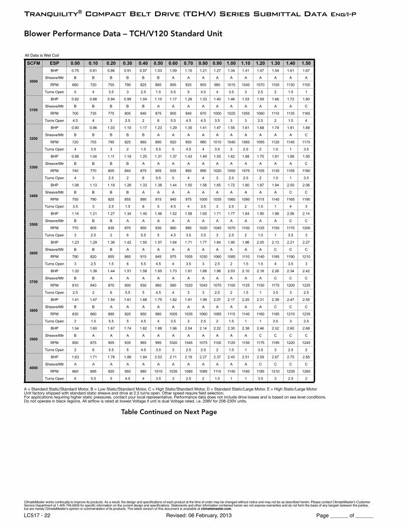
A = Standard Static/Standard Motor, B = Low Static/Standard Motor, C = High Static/Standard Motor, D = Standard Static/Large Motor, E = High Static/Large MotorUnit factory shipped with standard static sheave and drive at 2.5 turns open. Other speed require fi eld selection.For applications requiring higher static pressures, contact your local representative. Performance data does not include drive losses and is based on sea level conditions.Do not operate in black regions. All airfl ow is rated at lowest Voltage if unit is dual Voltage rated, i.e. 208V for 208-230V units.
ClimateMaster works continually to improve its products. As a result, the design and specifi cations of each product at the time of order may be changed without notice and may not be as described herein. Please contact ClimateMaster's Customer Service Department at 1-405-745-6000 for specifi c information on the current design and specifi cations. Statements and other information contained herein are not express warranties and do not form the basis of any bargain between the parties, but are merely ClimateMaster's opinion or commendation of its products. The latest version of this document is available at climatemaster.com.
Page ______ of ______Revised: 06 February, 2013LC517 - 20
Tranquility® Compact Belt Drive (TCH/V) Series Submittal Data Eng/I-P
Blower Performance Data – TCH/V096 Standard Unit
All Data is Wet Coil
A = Standard Static/Standard Motor, B = Low Static/Standard Motor, C = High Static/Standard Motor, D = Standard Static/Large Motor, E = High Static/Large MotorUnit factory shipped with standard static sheave and drive at 2.5 turns open. Other speed require fi eld selection.For applications requiring higher static pressures, contact your local representative. Performance data does not include drive losses and is based on sea level conditions.Do not operate in black regions. All airfl ow is rated at lowest Voltage if unit is dual Voltage rated, i.e. 208V for 208-230V units.
ClimateMaster works continually to improve its products. As a result, the design and specifi cations of each product at the time of order may be changed without notice and may not be as described herein. Please contact ClimateMaster's Customer Service Department at 1-405-745-6000 for specifi c information on the current design and specifi cations. Statements and other information contained herein are not express warranties and do not form the basis of any bargain between the parties, but are merely ClimateMaster's opinion or commendation of its products. The latest version of this document is available at climatemaster.com.
Page ______ of ______Revised: 06 February, 2013LC517 - 21
Tranquility® Compact Belt Drive (TCH/V) Series Submittal Data Eng/I-P
A = Standard Static/Standard Motor, B = Low Static/Standard Motor, C = High Static/Standard Motor, D = Standard Static/Large Motor, E = High Static/Large MotorUnit factory shipped with standard static sheave and drive at 2.5 turns open. Other speed require fi eld selection.For applications requiring higher static pressures, contact your local representative. Performance data does not include drive losses and is based on sea level conditions.Do not operate in black regions. All airfl ow is rated at lowest Voltage if unit is dual Voltage rated, i.e. 208V for 208-230V units.
ClimateMaster works continually to improve its products. As a result, the design and specifi cations of each product at the time of order may be changed without notice and may not be as described herein. Please contact ClimateMaster's Customer Service Department at 1-405-745-6000 for specifi c information on the current design and specifi cations. Statements and other information contained herein are not express warranties and do not form the basis of any bargain between the parties, but are merely ClimateMaster's opinion or commendation of its products. The latest version of this document is available at climatemaster.com.
Page ______ of ______Revised: 06 February, 2013LC517 - 22
Tranquility® Compact Belt Drive (TCH/V) Series Submittal Data Eng/I-P
A = Standard Static/Standard Motor, B = Low Static/Standard Motor, C = High Static/Standard Motor, D = Standard Static/Large Motor, E = High Static/Large MotorUnit factory shipped with standard static sheave and drive at 2.5 turns open. Other speed require fi eld selection.For applications requiring higher static pressures, contact your local representative. Performance data does not include drive losses and is based on sea level conditions.Do not operate in black regions. All airfl ow is rated at lowest Voltage if unit is dual Voltage rated, i.e. 208V for 208-230V units.
ClimateMaster works continually to improve its products. As a result, the design and specifi cations of each product at the time of order may be changed without notice and may not be as described herein. Please contact ClimateMaster's Customer Service Department at 1-405-745-6000 for specifi c information on the current design and specifi cations. Statements and other information contained herein are not express warranties and do not form the basis of any bargain between the parties, but are merely ClimateMaster's opinion or commendation of its products. The latest version of this document is available at climatemaster.com.
Page ______ of ______Revised: 06 February, 2013LC517 - 23
Tranquility® Compact Belt Drive (TCH/V) Series Submittal Data Eng/I-P
A = Standard Static/Standard Motor, B = Low Static/Standard Motor, C = High Static/Standard Motor, D = Standard Static/Large Motor, E = High Static/Large MotorUnit factory shipped with standard static sheave and drive at 2.5 turns open. Other speed require fi eld selection.For applications requiring higher static pressures, contact your local representative. Performance data does not include drive losses and is based on sea level conditions.Do not operate in black regions. All airfl ow is rated at lowest Voltage if unit is dual Voltage rated, i.e. 208V for 208-230V units.
ClimateMaster works continually to improve its products. As a result, the design and specifi cations of each product at the time of order may be changed without notice and may not be as described herein. Please contact ClimateMaster's Customer Service Department at 1-405-745-6000 for specifi c information on the current design and specifi cations. Statements and other information contained herein are not express warranties and do not form the basis of any bargain between the parties, but are merely ClimateMaster's opinion or commendation of its products. The latest version of this document is available at climatemaster.com.
Page ______ of ______Revised: 06 February, 2013LC517 - 24
Tranquility® Compact Belt Drive (TCH/V) Series Submittal Data Eng/I-P
A = Standard Static/Standard Motor, B = Low Static/Standard Motor, C = High Static/Standard Motor, D = Standard Static/Large Motor, E = High Static/Large MotorUnit factory shipped with standard static sheave and drive at 2.5 turns open. Other speed require fi eld selection.For applications requiring higher static pressures, contact your local representative. Performance data does not include drive losses and is based on sea level conditions.Do not operate in black regions. All airfl ow is rated at lowest Voltage if unit is dual Voltage rated, i.e. 208V for 208-230V units.
All Data is Wet Coil
ClimateMaster works continually to improve its products. As a result, the design and specifi cations of each product at the time of order may be changed without notice and may not be as described herein. Please contact ClimateMaster's Customer Service Department at 1-405-745-6000 for specifi c information on the current design and specifi cations. Statements and other information contained herein are not express warranties and do not form the basis of any bargain between the parties, but are merely ClimateMaster's opinion or commendation of its products. The latest version of this document is available at climatemaster.com.
Page ______ of ______Revised: 06 February, 2013LC517 - 25
Tranquility® Compact Belt Drive (TCH/V) Series Submittal Data Eng/I-P
Blower Performance Data – TCV192 Standard Unit
A = Standard Static/Standard Motor, B = Low Static/Standard Motor, C = High Static/Standard Motor, D = Standard Static/Large Motor, E = High Static/Large MotorUnit factory shipped with standard static sheave and drive at 2.5 turns open. Other speed require fi eld selection.For applications requiring higher static pressures, contact your local representative. Performance data does not include drive losses and is based on sea level conditions.Do not operate in black regions. All airfl ow is rated at lowest Voltage if unit is dual Voltage rated, i.e. 208V for 208-230V units.
ClimateMaster works continually to improve its products. As a result, the design and specifi cations of each product at the time of order may be changed without notice and may not be as described herein. Please contact ClimateMaster's Customer Service Department at 1-405-745-6000 for specifi c information on the current design and specifi cations. Statements and other information contained herein are not express warranties and do not form the basis of any bargain between the parties, but are merely ClimateMaster's opinion or commendation of its products. The latest version of this document is available at climatemaster.com.
Page ______ of ______Revised: 06 February, 2013LC517 - 26
Tranquility® Compact Belt Drive (TCH/V) Series Submittal Data Eng/I-P
A = Standard Static/Standard Motor, B = Low Static/Standard Motor, C = High Static/Standard Motor, D = Standard Static/Large Motor, E = High Static/Large MotorUnit factory shipped with standard static sheave and drive at 2.5 turns open. Other speed require fi eld selection.For applications requiring higher static pressures, contact your local representative. Performance data does not include drive losses and is based on sea level conditions.Do not operate in black regions. All airfl ow is rated at lowest Voltage if unit is dual Voltage rated, i.e. 208V for 208-230V units.
ClimateMaster works continually to improve its products. As a result, the design and specifi cations of each product at the time of order may be changed without notice and may not be as described herein. Please contact ClimateMaster's Customer Service Department at 1-405-745-6000 for specifi c information on the current design and specifi cations. Statements and other information contained herein are not express warranties and do not form the basis of any bargain between the parties, but are merely ClimateMaster's opinion or commendation of its products. The latest version of this document is available at climatemaster.com.
Page ______ of ______Revised: 06 February, 2013LC517 - 27
Tranquility® Compact Belt Drive (TCH/V) Series Submittal Data Eng/I-P
Blower Performance Data – TCV240 Standard Unit
8600
BHP 3.81 3.98 4.12 4.29 4.46 4.62 4.78 4.94 5.10 5.28 5.48 5.64 5.84 6.04 6.20Sheave/Mtr A A A A A A A A E E E E E E E
A = Standard Static/Standard Motor, B = Low Static/Standard Motor, C = High Static/Standard Motor, D = Standard Static/Large Motor, E = High Static/Large MotorUnit factory shipped with standard static sheave and drive at 2.5 turns open. Other speed require fi eld selection.For applications requiring higher static pressures, contact your local representative. Performance data does not include drive losses and is based on sea level conditions.Do not operate in black regions. All airfl ow is rated at lowest Voltage if unit is dual Voltage rated, i.e. 208V for 208-230V units.
ClimateMaster works continually to improve its products. As a result, the design and specifi cations of each product at the time of order may be changed without notice and may not be as described herein. Please contact ClimateMaster's Customer Service Department at 1-405-745-6000 for specifi c information on the current design and specifi cations. Statements and other information contained herein are not express warranties and do not form the basis of any bargain between the parties, but are merely ClimateMaster's opinion or commendation of its products. The latest version of this document is available at climatemaster.com.
Page ______ of ______Revised: 06 February, 2013LC517 - 28
Tranquility® Compact Belt Drive (TCH/V) Series Submittal Data Eng/I-P
A = Standard Static/Standard Motor, B = Low Static/Standard Motor, C = High Static/Standard Motor, D = Standard Static/Large Motor, E = High Static/Large MotorUnit factory shipped with standard static sheave and drive at 2.5 turns open. Other speed require fi eld selection.For applications requiring higher static pressures, contact your local representative. Performance data does not include drive losses and is based on sea level conditions.Do not operate in black regions. All airfl ow is rated at lowest Voltage if unit is dual Voltage rated, i.e. 208V for 208-230V units.
ClimateMaster works continually to improve its products. As a result, the design and specifi cations of each product at the time of order may be changed without notice and may not be as described herein. Please contact ClimateMaster's Customer Service Department at 1-405-745-6000 for specifi c information on the current design and specifi cations. Statements and other information contained herein are not express warranties and do not form the basis of any bargain between the parties, but are merely ClimateMaster's opinion or commendation of its products. The latest version of this document is available at climatemaster.com.
Page ______ of ______Revised: 06 February, 2013LC517 - 29
Tranquility® Compact Belt Drive (TCH/V) Series Submittal Data Eng/I-P
All units have grommet compressor mountings, and 1/2" & 1-3/4" electrical knockouts.
Unit Maximum Water Working Pressure Max Pressure PSIG [kPa]
Base Unit 300 [2068]
ClimateMaster works continually to improve its products. As a result, the design and specifi cations of each product at the time of order may be changed without notice and may not be as described herein. Please contact ClimateMaster's Customer Service Department at 1-405-745-6000 for specifi c information on the current design and specifi cations. Statements and other information contained herein are not express warranties and do not form the basis of any bargain between the parties, but are merely ClimateMaster's opinion or commendation of its products. The latest version of this document is available at climatemaster.com.
Page ______ of ______Revised: 06 February, 2013LC517 - 30
Tranquility® Compact Belt Drive (TCH/V) Series Submittal Data Eng/I-P
HANGER BRACKET DIMENSIONS87”
[221cm]
1.0”[2.54cm]
PLAN VIEWTOP
4.3”[10.8cm]
34.1”[86.6cm]
FR
ON
T
CONTROL BOX
U
T
S V
1.3”[3.3cm]
condensate LEFT RETURN LEFT VIEW-AIR COIL SIDE
LEFT RETURN END DISCHARGE
CBP
EAP
BSP
CAP
CAP
FRONT
ED
F
G
CAP
CBP
CAP
EAP
BSP
FRONT
FR
ON
T
CONTROL BOX
PLAN VIEWTOP
V S U
RIGHT RETURN RIGHT VIEW-AIR COIL SIDE
RIGHT RETURN END DISCHARGE
1.3”[3.3cm]
condensate drain
3
TCH072-120 Dimensional Data
LEFT RETURN STRAIGHT DISCHARGE
CAP
CAP
FRONT
BSPA
EAP
CBP
BC
O
PQRK
M
F
G E
D
BSP
RIGHT RETURN STRAIGHT DISCHARGE
1
EAP
2 CAP
CAP 2
FRONT
CBP1
5
4
LEGEND
CAP=Compressor Access PanelCBP=Control Box PanelBSP=Blower Service PanelEAP=Expansion Valve Access panel1=Water Outlet 1-1/4” FPT (072-096) 1-1/2” FPT (120)2=Water Inlet 1-1/4” FPT (072-096) 1-1/2” FPT (120)3=Condensate 3/4” FPT4=High Voltage 1-1/8” [2.9cm] KO5=Low Voltage 7/8” [2.2cm] KO
SERVICE ACCESS3’ (91 cm.)
Note 5, 6
Note 6
Note 6
Note 6
ALL CONFIGURATIONS REQUIRE SERVICE ACCESS AREADESCRIBED IN NOTES 5 AND 6.
NOTES:- All dimensions in table are inches (cm).
1. Access is required for all removable panels and installer should take care to comply with all building codes and allow adequate clearance for future field service.
2. Water inlet and water outlet connections are available on either side (left or right) of the unit. Qty (2x) MPT Plugs are shipped loose in a plastic bag tied to the water leg in front of the unit. Installer must plug water inlet/outlet side not being connected to.
3. Condensate drain is available on end opposite compressor.
4. Electrical access is available on either side (left or right) of the front.
5. Electric box is on right side. It can be field converted to left side. Conversion should only be attempted by qualified service technician. If electric box relocated to opposite side, and water connected to opposite side, then this access is not required.
6. Units require 3’ (9.1 cm) clearance for water connections, CAP, CSP, EAP and BSP service access.7. Overall cabinet width dimensions does not include filter rail and duct flange.
TCH072-120 Dimensional Data
Model
Overall CabinetDischarge Connections
Duct Flange Water Connections Electrical Knockouts
ClimateMaster works continually to improve its products. As a result, the design and specifi cations of each product at the time of order may be changed without notice and may not be as described herein. Please contact ClimateMaster's Customer Service Department at 1-405-745-6000 for specifi c information on the current design and specifi cations. Statements and other information contained herein are not express warranties and do not form the basis of any bargain between the parties, but are merely ClimateMaster's opinion or commendation of its products. The latest version of this document is available at climatemaster.com.
Page ______ of ______Revised: 06 February, 2013LC517 - 31
Tranquility® Compact Belt Drive (TCH/V) Series Submittal Data Eng/I-P
No. of Blowers 1 2 3Blower Wheel Size D x W (in) [cm] 12 x 12 [30.48 x 30.48]Water Connection SizeFPT (in) [mm] 1-1/4" [31.8] 1-1/2" [38.1] 2" [50.8] 2-1/2" [63.5]Coax VolumeVolume (US Gallons) [liters] 1.62 [6.13] 1.81 [6.85] 2.40 [9.08] 3.62 [13.70] 4.83 [18.28] 4.90 [18.55] 7.39 [27.98]Condensate Connection SizeFPT (in) [mm] 3/4" [19.1]Air Coil Data
Air Coil Dimensions H x W (in) [cm] 32 x 34 [81.28 x 86.36] 36 x 36 [91.44 x 91.44] 36 x 76 [91.44 x 193.04]
Air Coil Total Face Area (ft2) [m2] 7.6 [0.71] 9.0 [0.84] 19 [1.77]Air Coil Tube Size (in) [cm] 3/8" [0.953]Air Coil Fin Spacing (fpi) [fi ns per cm] 14 [5.5] 12 [4.72]
Air Coil Number of Rows 3 2 3 4Miscellaneous DataFilter Standard - 1" [25.4mm] Throwaway (qty) (in) [cm] (QTY.4) 20 x 20 [50.8 x 50.8] (QTY.4) 20 x 25 [50.80 x 63.5]
All units have grommet compressor mountings, and 1/2" & 1-3/4" electrical knockouts.
Unit Maximum Water Working Pressure Max Pressure PSIG [kPa]
Base Unit 300 [2068]
ClimateMaster works continually to improve its products. As a result, the design and specifi cations of each product at the time of order may be changed without notice and may not be as described herein. Please contact ClimateMaster's Customer Service Department at 1-405-745-6000 for specifi c information on the current design and specifi cations. Statements and other information contained herein are not express warranties and do not form the basis of any bargain between the parties, but are merely ClimateMaster's opinion or commendation of its products. The latest version of this document is available at climatemaster.com.
Page ______ of ______Revised: 06 February, 2013LC517 - 32
Tranquility® Compact Belt Drive (TCH/V) Series Submittal Data Eng/I-P
TCV
Model
Overall Cabinet Discharge Connection Duct Flange Water Connections Electric Knockouts Return Air Connections Using
LEGEND TCV072-096 TCV120Water Inlet (See Note 2)Water Outlet (See Note 2)Condensate Drain (See Note 3)High Voltage Access (See Note 4)Low Voltage Access (See Note 4)
1-1/4” FPT1-1/4” FPT
1-1/2” FPT1-1/2” FPT
1” FPT1-3/8” [3.49 CM]
7/8” [2.2 CM]BSP - Blower Service Panel CAP - Control Access PanelCSP - Compressor Access PanelMSP - Motor Service PanelNRP - Non Removable PanelUPA - Upper Pulley Access
12345
FRONT RETURN REAR DISCHARGE (FR/RD)REAR RETURN FRONT DISCHARGE (RR/FD)
REAR RETURN TOP DISCHARGE (RR/TD) FRONT RETURN TOP DISCHARGE (FR/TD)
NOTES:All dimensions in table are inches (cm)1. While access to all removable panels may not be required, installer should take care to
comply with all building codes and allow adequate clearance for future field service.2. Water inlet and water outlet connections are factory shipped on the left side. Union allows
field conversion to right side. 3. Condensate drain is available on either side (left or right) of unit. Drain hose and drain
connection will be tied inside the unit. Installer will untie the drain hose, form trap, and connect to the condensate drain hole of installer’s choice.
4. Electrical access is available on either side (left or right) of unit and is also available in the front on the left or right side of the unit.
5. Overall width - Add 3.12” (8cm) for 1“ (2.5cm) or 2” (5cm) Filter Frame; or 5.12” (13cm) for 4” (10.2cm) and for front or rear supply add additional 1.06” (2.7cm) for supply duct collar.
6. Overall cabinet height dimension does not include duct flange for top discharge configuration.
7. While access to all removable panels may not be required, installer should take care to comply with all building codes and allow adequate clearance for future field service.
8. Units require 3 feet(91 cm) clearance, CAP, CSP, MSP and BSP service access.9. Side service access must be 2 feet (9.4cm) on any side that connections are made. 10. Filter removal is from bottom of frame, allow 2 feet (9.4cm) access for servicing.
BSPUPA
ALL CONFIGURATIONS REQUIRE SERVICE ACCESS AREADESCRIBED IN NOTES 7, 8, 9, AND 10.
(See Notes 7 and 8)
(See Notes 7 and 10)
Note 2
ALL CONFIGURATIONS
BLOWER TO AIR COIL RELATIONSHIP FOR
TOP DISCHARGE 072-120
BSP+MSP
CSP
(See Note 6)
Control Box
Control Box
Control Box
Control Box
ClimateMaster works continually to improve its products. As a result, the design and specifi cations of each product at the time of order may be changed without notice and may not be as described herein. Please contact ClimateMaster's Customer Service Department at 1-405-745-6000 for specifi c information on the current design and specifi cations. Statements and other information contained herein are not express warranties and do not form the basis of any bargain between the parties, but are merely ClimateMaster's opinion or commendation of its products. The latest version of this document is available at climatemaster.com.
Page ______ of ______Revised: 06 February, 2013LC517 - 33
Tranquility® Compact Belt Drive (TCH/V) Series Submittal Data Eng/I-P
TCV160-240 Dimensional Data
REAR RETURN TOP DISCHARGE (RR/TD)
FRONT RETURN REAR DISCHARGE (FR/RD)REAR RETURN FRONT DISCHARGE (RR/FD)
FRONT RETURN TOP DISCHARGE (FR/TD)
ALL CONFIGURATIONS REQUIRE SERVICE ACCESS AREADESCRIBED IN NOTES 7, 8, 9, AND 10.
ALL CONFIGURATIONS
SIDE SERVICE ACCESS
(See Notes 7 and 9)
See Notes 7 and 10
SERVICE ACCESS3’ (91 CM)
FRONT AND BACK(See Notes 7 and 8)
BLOWER TO AIR COIL RELATIONSHIP FOR
REAR OR FRONT DISCHARGE 160-240
NOTES:All dimensions in table are inches (cm)1. While access to all removable panels may not be required, installer should take care to
comply with all building codes and allow adequate clearance for future field service.2. Water inlet and water outlet connections are factory shipped on the left side. Union allows
field conversion to right side. 3. Condensate drain is available on either side (left or right) of unit. Drain hose and drain
connection will be tied inside the unit. Installer will untie the drain hose, form trap, and connect to the condensate drain hole of installer’s choice.
4. Electrical access is available on either side (left or right) of unit and is also available in the front on the left or right side of the unit.
5. Overall width - Add 3.12” (8cm) for 1“ (2.5cm) or 2” (5cm) Filter Frame; or 5.12” (13cm) for 4” (10.2cm) and for front or rear supply add additional 1.06” (2.7cm) for supply duct collar.
6. Overall cabinet height dimension does not include duct flange for top discharge configuration.
7. While access to all removable panels may not be required, installer should take care to comply with all building codes and allow adequate clearance for future field service.
8. Units require 3 feet(91 cm) clearance, CAP, CSP, MSP and BSP service access.9. Side service access must be 2 feet (9.4cm) on any side that connections are made. 10. Filter removal is from bottom of frame, allow 2 feet (9.4cm) access for servicing.
BLOWER TO AIR COIL RELATIONSHIP FOR
TOP DISCHARGE 160-240
BLOWER ROTATION
(See Note 6)
(See Note 5)
Note 2
Model
Overall Cabinet Discharge Connection Duct Flange Water Connections Electrical Knockouts Return Air Connections
ClimateMaster works continually to improve its products. As a result, the design and specifi cations of each product at the time of order may be changed without notice and may not be as described herein. Please contact ClimateMaster's Customer Service Department at 1-405-745-6000 for specifi c information on the current design and specifi cations. Statements and other information contained herein are not express warranties and do not form the basis of any bargain between the parties, but are merely ClimateMaster's opinion or commendation of its products. The latest version of this document is available at climatemaster.com.
Page ______ of ______Revised: 06 February, 2013LC517 - 34
Tranquility® Compact Belt Drive (TCH/V) Series Submittal Data Eng/I-P
TCV300 Dimensional Data
REAR RETURN TOP DISCHARGE (RR/TD)
FRONT RETURN REAR DISCHARGE (FR/RD)REAR RETURN FRONT DISCHARGE (RR/FD)
FRONT RETURN TOP DISCHARGE (FR/TD)
ALL CONFIGURATIONS REQUIRE SERVICE ACCESS AREADESCRIBED IN NOTES 7, 8, 9, AND 10.
SIDE SERVICE ACCESS
(See Notes 7 and 9)
See Notes 7 and 10
SERVICE ACCESS3’ (91 CM)
FRONT AND BACK(See Notes 7 and 8)
NOTES:All dimensions in table are inches (cm)1. While access to all removable panels may not be required, installer should take care to
comply with all building codes and allow adequate clearance for future field service.2. Water inlet and water outlet connections are factory shipped on the left side. Union allows
field conversion to right side. 3. Condensate drain is available on either side (left or right) of unit. Drain hose and drain
connection will be tied inside the unit. Installer will untie the drain hose, form trap, and connect to the condensate drain hole of installer’s choice.
4. Electrical access is available on either side (left or right) of unit and is also available in the front on the left or right side of the unit.
5. Overall width - Add 3.12” (8cm) for 1“ (2.5cm) or 2” (5cm) Filter Frame; or 5.12” (13cm) for 4” (10.2cm) and for front or rear supply add additional 1.06” (2.7cm) for supply duct collar.
6. Overall cabinet height dimension does not include duct flange for top discharge configuration.
7. While access to all removable panels may not be required, installer should take care to comply with all building codes and allow adequate clearance for future field service.
8. Units require 3 feet(91 cm) clearance, CAP, CSP, MSP and BSP service access.9. Side service access must be 2 feet (9.4cm) on any side that connections are made. 10. Filter removal is from bottom of frame, allow 2 feet (9.4cm) access for servicing.
(See Note 5)
ALL CONFIGURATIONS
Note 2
(See Note 6)
BLOWER ROTATION
BLOWER TO AIR COIL RELATIONSHIP FOR
TOP DISCHARGE 300
BLOWER TO AIR COIL RELATIONSHIP FOR
REAR OR FRONT DISCHARGE 300 ONLY
Model
Overall Cabinet Discharge Connection Duct Flange Water Connections Electrical Knockouts Return Air Connections
ClimateMaster works continually to improve its products. As a result, the design and specifi cations of each product at the time of order may be changed without notice and may not be as described herein. Please contact ClimateMaster's Customer Service Department at 1-405-745-6000 for specifi c information on the current design and specifi cations. Statements and other information contained herein are not express warranties and do not form the basis of any bargain between the parties, but are merely ClimateMaster's opinion or commendation of its products. The latest version of this document is available at climatemaster.com.
Page ______ of ______Revised: 06 February, 2013LC517 - 35
Tranquility® Compact Belt Drive (TCH/V) Series Submittal Data Eng/I-P
Model # Voltage Code Voltage Min/Max
Voltage Blower Option Compressor Fan Motor FLA
Total Unit FLA
Min Circuit Amp
Max Fuse/HACRQTY RLA LRA
TCH/V072
H 208-3-60 197/254 A, B, C 2 10.4 73.0 3.2 24.0 26.6 35H 208-3-60 197/254 D, E 2 10.4 73.0 6.0 26.8 29.4 35F 460-3-60 414/506 A, B, C 2 5.8 38.0 1.6 13.2 14.7 20F 460-3-60 414/506 D, E 2 5.8 38.0 2.9 14.5 16.0 20N 575-3-60 518/633 A, B, C 2 3.8 36.5 1.2 8.8 9.7 15N 575-3-60 518/633 D, E 2 3.8 36.5 2.4 10.0 10.9 15U 400-3-50 360/440 A, B, C 2 5.4 38.0 1.8 12.6 14.0 15
TCH/V096
H 208-3-60 197/254 A, B, C 2 13.7 83.1 6.0 33.4 36.8 50H 208-3-60 197/254 D, E 2 13.7 83.1 8.5 35.9 39.3 50F 460-3-60 414/506 A, B, C 2 6.2 41.0 2.9 15.3 16.8 20F 460-3-60 414/506 D, E 2 6.2 41.0 4.1 16.5 18.0 20N 575-3-60 518/633 A, B, C 2 4.8 33.0 2.4 12.0 13.2 15N 575-3-60 518/633 D, E 2 4.8 33.0 3.2 12.8 14.0 15U 400-3-50 360/440 A, B, C 2 6.1 43.0 3.4 15.6 17.1 20
TCH/V120
H 208-3-60 197/254 A, B, C 2 15.6 110.0 8.5 39.7 43.6 50H 208-3-60 197/254 D, E 2 15.6 110.0 13.8 45.0 48.9 60F 460-3-60 414/506 A, B, C 2 7.8 52.0 4.1 19.7 21.7 25F 460-3-60 414/506 D, E 2 7.8 52.0 6.5 22.1 24.1 30N 575-3-60 518/633 A, B, C 2 5.8 38.9 3.2 14.8 16.3 20N 575-3-60 518/633 D, E 2 5.8 38.9 5.2 16.8 18.3 20U 400-3-50 360/440 A, B, C 2 7.8 51.5 4.9 20.5 22.5 30
TCV160
H 208-3-60 197/254 A, B, C 2 23.2 164.0 8.5 54.9 60.7 80H 208-3-60 197/254 D, E 2 23.2 164.0 13.8 60.2 66.0 80F 460-3-60 414/506 A, B, C 2 11.2 75.0 4.1 26.5 29.3 40F 460-3-60 414/506 D, E 2 11.2 75.0 6.5 28.9 31.7 40N 575-3-60 518/633 A, B, C 2 7.9 54.0 3.2 19.0 21.0 25N 575-3-60 518/633 D, E 2 7.9 54.0 5.2 21.0 23.0 30U 400-3-50 360/440 A, B, C 2 11.2 75.0 4.9 27.3 30.1 40
TCV192
H 208-3-60 197/254 A, B, C 2 25.0 164.0 8.5 58.5 64.8 90H 208-3-60 197/254 D, E 2 25.0 164.0 13.8 63.8 70.1 90F 460-3-60 414/506 A, B, C 2 12.2 100.0 4.1 28.5 31.6 40F 460-3-60 414/506 D, E 2 12.2 100.0 6.5 30.9 34.0 45N 575-3-60 518/633 A, B, C 2 9.0 78.0 3.2 21.2 23.5 30N 575-3-60 518/633 D, E 2 9.0 78.0 5.2 23.2 25.4 30U 400-3-50 360/440 A, B, C 2 12.2 101.0 4.9 29.3 32.4 40
TCV240
H 208-3-60 197/254 A, B, C 2 30.1 225.0 13.8 74.0 81.5 110H 208-3-60 197/254 D, E 2 30.1 225.0 21.0 81.2 88.7 110F 460-3-60 414/506 A, B, C 2 16.7 114.0 6.5 39.9 44.1 60F 460-3-60 414/506 D, E 2 16.7 114.0 9.9 43.3 47.5 60N 575-3-60 518/633 A, B, C 2 12.2 80.0 5.2 29.6 32.6 40N 575-3-60 518/633 D, E 2 12.2 80.0 8.0 32.4 35.5 45U 400-3-50 360/440 A, B, C 2 16.7 111.0 7.8 41.2 45.4 60
TCV300
H 208-3-60 197/254 A, B, C 2 48.1 245.0 21.0 117.2 129.2 150H 208-3-60 197/254 D, E 2 48.1 245.0 26.0 122.2 134.2 150F 460-3-60 414/506 A, B, C 2 18.6 125.0 9.9 47.1 51.8 70F 460-3-60 414/506 D, E 2 18.6 125.0 12.5 49.7 54.4 70N 575-3-60 518/633 A, B, C 2 14.7 100.0 8.0 37.4 41.1 50N 575-3-60 518/633 D, E 2 14.7 100.0 10.2 39.6 43.3 50U 400-3-50 360/440 A, B, C 2 18.6 118.0 21.0 58.2 62.9 80
TCH/V Electrical Data – Standard
HACR circuit breaker in USA onlyAll fuses Class RK-5
ClimateMaster works continually to improve its products. As a result, the design and specifi cations of each product at the time of order may be changed without notice and may not be as described herein. Please contact ClimateMaster's Customer Service Department at 1-405-745-6000 for specifi c information on the current design and specifi cations. Statements and other information contained herein are not express warranties and do not form the basis of any bargain between the parties, but are merely ClimateMaster's opinion or commendation of its products. The latest version of this document is available at climatemaster.com.
Page ______ of ______Revised: 06 February, 2013LC517 - 36
Tranquility® Compact Belt Drive (TCH/V) Series Submittal Data Eng/I-P
TCH/V Electrical Data - Dual Point Power
Model # Voltage Code Voltage Min/Max
VoltageBlower Option
Compressor Power Supply Emergency Power Supply
QTY RLA LRA Total Comp FLA
Comp MCA
Comp Max
Fuse/ HACR
Fan Motor FLA
Fan MCA
Fan Max Fuse/ HACR
TCH/V072
H 208-3-60 197/254 A, B, C 2 10.4 73.0 20.8 23.4 30 3.2 4.0 15H 208-3-60 197/254 D, E 2 10.4 73.0 20.8 23.4 30 6.0 7.5 15F 460-3-60 414/506 A, B, C 2 5.8 38.0 11.6 13.1 15 1.6 2.0 15F 460-3-60 414/506 D, E 2 5.8 38.0 11.6 13.1 15 2.9 3.6 15N 575-3-60 518/633 A, B, C 2 3.8 36.5 7.6 8.6 15 1.2 1.5 15N 575-3-60 518/633 D, E 2 3.8 36.5 7.6 8.6 15 2.4 3.0 15U 400-3-50 360/440 A, B, C 2 5.4 38.0 10.8 12.2 15 1.8 2.2 15
TCH/V096
H 208-3-60 197/254 A, B, C 2 13.7 83.1 27.4 30.8 40 6.0 7.5 15H 208-3-60 197/254 D, E 2 13.7 83.1 27.4 30.8 40 8.5 10.6 15F 460-3-60 414/506 A, B, C 2 6.2 41.0 12.4 13.9 20 2.9 3.6 15F 460-3-60 414/506 D, E 2 6.2 41.0 12.4 13.9 20 4.1 5.1 15N 575-3-60 518/633 A, B, C 2 4.8 33.0 9.6 10.8 15 2.4 3.0 15N 575-3-60 518/633 D, E 2 4.8 33.0 9.6 10.8 15 3.2 4.0 15U 400-3-50 360/440 A, B, C 2 6.1 43.0 12.2 13.7 15 3.4 4.3 15
TCH/V120
H 208-3-60 197/254 A, B, C 2 15.6 110.0 31.2 35.1 50 8.5 10.6 15H 208-3-60 197/254 D, E 2 15.6 110.0 31.2 35.1 50 13.8 17.3 30F 460-3-60 414/506 A, B, C 2 7.8 52.0 15.6 17.6 25 4.1 5.1 15F 460-3-60 414/506 D, E 2 7.8 52.0 15.6 17.6 25 6.5 8.1 15N 575-3-60 518/633 A, B, C 2 5.8 38.9 11.6 13.1 15 3.2 4.0 15N 575-3-60 518/633 D, E 2 5.8 38.9 11.6 13.1 15 5.2 6.5 15U 400-3-50 360/440 A, B, C 2 7.8 51.5 15.6 17.6 25 4.9 6.1 15
TCV160
H 208-3-60 197/254 A, B, C 2 23.2 164.0 46.4 52.2 70 8.5 10.6 15H 208-3-60 197/254 D, E 2 23.2 164.0 46.4 52.2 70 13.8 17.3 30F 460-3-60 414/506 A, B, C 2 11.2 75.0 22.4 25.2 35 4.1 5.1 15F 460-3-60 414/506 D, E 2 11.2 75.0 22.4 25.2 35 6.5 8.1 15N 575-3-60 518/633 A, B, C 2 7.9 54.0 15.8 17.8 25 3.2 4.0 15N 575-3-60 518/633 D, E 2 7.9 54.0 15.8 17.8 25 5.2 6.5 15U 400-3-50 360/440 A, B, C 2 11.2 75.0 22.4 25.2 35 4.9 6.1 15
TCV192
H 208-3-60 197/254 A, B, C 2 25.0 164.0 50.0 56.3 80 8.5 10.6 15H 208-3-60 197/254 D, E 2 25.0 164.0 50.0 56.3 80 13.8 17.3 30F 460-3-60 414/506 A, B, C 2 12.2 100.0 24.4 27.4 35 4.1 5.1 15F 460-3-60 414/506 D, E 2 12.2 100.0 24.4 27.4 35 6.5 8.1 15N 575-3-60 518/633 A, B, C 2 9.0 78.0 18.0 20.3 25 3.2 4.0 15N 575-3-60 518/633 D, E 2 9.0 78.0 18.0 20.3 25 5.2 6.5 15U 400-3-50 360/440 A, B, C 2 12.2 101.0 24.4 27.4 35 4.9 6.1 15
TCV240
H 208-3-60 197/254 A, B, C 2 30.1 225.0 60.2 67.7 90 13.8 17.3 30H 208-3-60 197/254 D, E 2 30.1 225.0 60.2 67.7 90 21.0 26.3 45F 460-3-60 414/506 A, B, C 2 16.7 114.0 33.4 37.6 50 6.5 8.1 15F 460-3-60 414/506 D, E 2 16.7 114.0 33.4 37.6 50 9.9 12.4 20N 575-3-60 518/633 A, B, C 2 12.2 80.0 24.4 27.5 35 5.2 6.5 15N 575-3-60 518/633 D, E 2 12.2 80.0 24.4 27.5 35 8.0 10.0 15U 400-3-50 360/440 A, B, C 2 16.7 111.0 33.4 37.6 50 7.8 9.8 15
TCV300
H 208-3-60 197/254 A, B, C 2 48.1 245.0 96.2 108.2 150 21.0 26.3 15H 208-3-60 197/254 D, E 2 48.1 245.0 96.2 108.2 150 26.0 32.5 50F 460-3-60 414/506 A, B, C 2 18.6 125.0 37.2 41.9 60 9.9 12.4 20F 460-3-60 414/506 D, E 2 18.6 125.0 37.2 41.9 60 12.5 15.6 25N 575-3-60 518/633 A, B, C 2 14.7 100.0 29.4 33.1 45 8.0 10.0 15N 575-3-60 518/633 D, E 2 14.7 100.0 29.4 33.1 45 10.2 12.8 20U 400-3-50 360/440 A, B, C 2 18.6 118.0 37.2 41.9 60 21.0 26.3 15
HACR circuit breaker in USA onlyAll fuses Class RK-5
ClimateMaster works continually to improve its products. As a result, the design and specifi cations of each product at the time of order may be changed without notice and may not be as described herein. Please contact ClimateMaster's Customer Service Department at 1-405-745-6000 for specifi c information on the current design and specifi cations. Statements and other information contained herein are not express warranties and do not form the basis of any bargain between the parties, but are merely ClimateMaster's opinion or commendation of its products. The latest version of this document is available at climatemaster.com.
Page ______ of ______Revised: 06 February, 2013LC517 - 37
Tranquility® Compact Belt Drive (TCH/V) Series Submittal Data Eng/I-P
TCH/V Series Wiring Diagram Matrix
ModelWiring Diagram
Part NumberElectrical Control
TCH/V072-300
96B0127N01
208-230/60/3460/60/3575/60/3
CXM
96B0127N02 DXM
96B0147N01 MPC
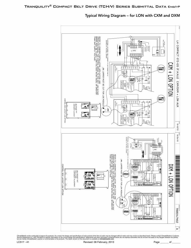
96B0147N02 LON
All wiring diagrams available at climatemaster.com.
ClimateMaster works continually to improve its products. As a result, the design and specifi cations of each product at the time of order may be changed without notice and may not be as described herein. Please contact ClimateMaster's Customer Service Department at 1-405-745-6000 for specifi c information on the current design and specifi cations. Statements and other information contained herein are not express warranties and do not form the basis of any bargain between the parties, but are merely ClimateMaster's opinion or commendation of its products. The latest version of this document is available at climatemaster.com.
Page ______ of ______Revised: 06 February, 2013LC517 - 38
Tranquility® Compact Belt Drive (TCH/V) Series Submittal Data Eng/I-P
Typical Wiring Diagram – Three Phase TCH/V072-300 with CXM Controller
hp
wr
ClimateMaster works continually to improve its products. As a result, the design and specifi cations of each product at the time of order may be changed without notice and may not be as described herein. Please contact ClimateMaster's Customer Service Department at 1-405-745-6000 for specifi c information on the current design and specifi cations. Statements and other information contained herein are not express warranties and do not form the basis of any bargain between the parties, but are merely ClimateMaster's opinion or commendation of its products. The latest version of this document is available at climatemaster.com.
Page ______ of ______Revised: 06 February, 2013LC517 - 39
Tranquility® Compact Belt Drive (TCH/V) Series Submittal Data Eng/I-P
Typical Wiring Diagram – Three Phase TCH/V072-300 with DXM
hp
ws
wtr o
ut
wtr in
hp
ws
hp
wr
°°
Sta
ge
2: 2
/1
T'S
tat: R
V o
n B
/RV
on
OD
eh
um
mo
de
: De
hu
m/N
orm
al
dd
c ou
tpu
t: dd
c/no
rma
lB
oile
rless O
p: E
na
ble
/Disa
ble
Bo
ilerle
ss Tem
p: 4
0°F
/50
°F
DIP
SW
ITCH T
'stat: H
ea
t Co
ol/H
ea
t Pu
mp
UP
S: D
isab
le/E
na
ble
5
PAC
KA
GE
8
S1
67
OF
F
2 134
ON
PAC
KA
GE
DIP
SW
ITCH
58
S2
67 234
OF
FO
N1
acc2
Fun
ction
s
fp1
/fp2
fau
lts: 3/1
fan
mo
de
: hi fa
n/a
uto
de
hu
m
Fun
ction
sa
cc1
ClimateMaster works continually to improve its products. As a result, the design and specifi cations of each product at the time of order may be changed without notice and may not be as described herein. Please contact ClimateMaster's Customer Service Department at 1-405-745-6000 for specifi c information on the current design and specifi cations. Statements and other information contained herein are not express warranties and do not form the basis of any bargain between the parties, but are merely ClimateMaster's opinion or commendation of its products. The latest version of this document is available at climatemaster.com.
Page ______ of ______Revised: 06 February, 2013LC517 - 40
Tranquility® Compact Belt Drive (TCH/V) Series Submittal Data Eng/I-P
Typical Wiring Diagram for MPC with CXM and DXM
AL2
DR
Y
NO
TE
1S
EE
°°
°°
RU
N
ClimateMaster works continually to improve its products. As a result, the design and specifi cations of each product at the time of order may be changed without notice and may not be as described herein. Please contact ClimateMaster's Customer Service Department at 1-405-745-6000 for specifi c information on the current design and specifi cations. Statements and other information contained herein are not express warranties and do not form the basis of any bargain between the parties, but are merely ClimateMaster's opinion or commendation of its products. The latest version of this document is available at climatemaster.com.
Page ______ of ______Revised: 06 February, 2013LC517 - 41
Tranquility® Compact Belt Drive (TCH/V) Series Submittal Data Eng/I-P
Typical Wiring Diagram – for LON with CXM and DXM
JW4
AL2
DR
Y
6Y
TE
ST
R
NS
B
OV
R
ES
D
P3
NO
1
NO
2
NC
2
CO
M
CO
M
NC
1
FP
1
FP
2
JW3
JW2
LPJW
1
UP
S: D
isab
le/E
na
ble
Bo
ilerle
ss: 40
°F/5
0°F
T'sta
t: He
at C
oo
l/He
at P
um
p
Bo
ilerle
ss: En
ab
le/D
isab
le
RE
LAY
OF
F
PAC
KA
GE
DIP
SW
ITCH
RE
LAY
R
AC
C2
8
S1
DD
C O
UT
PU
T: DD
C/N
OR
MA
L
RV
on
B/R
V o
n O
Un
it Sta
ge
: 2/1
De
hu
mid
/No
rma
l
3567 4 12
ON
HR
AC
C1
A C
PIN
ST
ES
T
P6
Fun
ction
s
Fun
ction
s
No
t Use
d
AC
C2
H: h
i fan
/de
hu
mid
8
PAC
KA
GE
DIP
SW
ITCH
S2
OF
F
3567 4 12
ON
AC
C1
RE
LAY
CO
MP
RCC
CC
G
FAU
LT
RE
LAY
RV
Low
N.O
.
Low
NO
TE
4S
EE
12
COD
C
EH
1
EH
2
24
V P7
R
9R
V1
0
FP
28 7
Y1
O/W
2
G W1
Y2P
2
AL1
CAL2
R
RP
1
678
ALA
RM
RE
LAY
35 4 2 1
C
CO
M2
RC
CO
M1
SS
C
NO
Micro
pro
cesso
r
STA
TU
S
Co
ntro
l Log
ic
DX
M
LOC
G
34
FP
15 1
HP
2
CO
M
NO
SP
EE
DR
ELA
YNC
FAN
FAN
EN
AB
LER
ELA
Y
CO
M
CO
M RE
LAY
FAN
EN
AB
LE
FAN
NC
RE
LAY
SP
EE
D
NO
CO
M
2H
P15
FP
1
4 3
G
LOC
DX
M
Co
ntro
l Log
ic
STA
TU
S
Micro
pro
cesso
r
NO
CS
S
CO
M1
CRC
OM
2
C
AL2
DR
Y JW4
1245 3
RE
LAY
ALA
RM
8 7 6
P1
R
RAL2
CAL1P
2
Y2W
1
G O/W
2
Y1
78F
P2
10
RV
9
R
P7
24
V
EH
2
EH
1
DC
CO
12
SE
EN
OT
E 4
Low
N.O
.
Low
RV
RE
LAY
FAU
LT
CC
G
CC
CO
MP
RR
ELA
Y
AC
C1
ON2 147 6 5 3
OF
FS2
DIP
SW
ITCH
PAC
KA
GE
8H
: hi fa
n/d
eh
um
id
AC
C2
No
t Use
d
Fun
ction
s
Fun
ction
s
P6
TE
ST
PIN
S
CA
AC
C1
R H
ON2 147 6 5 3
De
hu
mid
/No
rma
l
Un
it Sta
ge
: 2/1
RV
on
B/R
V o
n O
DD
C O
UT
PU
T: DD
C/N
OR
MA
L
S1
8
AC
C2
R
RE
LAY
DIP
SW
ITCH
PAC
KA
GE
OF
FR
ELA
Y
Bo
ilerle
ss: En
ab
le/D
isab
le
T'sta
t: He
at C
oo
l/He
at P
um
p
Bo
ilerle
ss: 40
°F/5
0°F
UP
S: D
isab
le/E
na
ble
JW1
LP
JW2
JW3
FP
2
FP
1
NC
1
CO
M
CO
M
NC
2
NO
2
NO
1
P3
ES
D
OV
R
NS
B RT
ES
TY
6
JW4
AL2
DR
Y
OF
F
8
S1
3567 4 12
ON
ON2 147 6 5 3
S1
8
OF
F
ClimateMaster works continually to improve its products. As a result, the design and specifi cations of each product at the time of order may be changed without notice and may not be as described herein. Please contact ClimateMaster's Customer Service Department at 1-405-745-6000 for specifi c information on the current design and specifi cations. Statements and other information contained herein are not express warranties and do not form the basis of any bargain between the parties, but are merely ClimateMaster's opinion or commendation of its products. The latest version of this document is available at climatemaster.com.
Page ______ of ______Revised: 06 February, 2013LC517 - 42
Tranquility® Compact Belt Drive (TCH/V) Series Submittal Data Eng/I-P
General:Furnish and install ClimateMaster Tranquility® TC Water Source Heat Pumps, as indicated on the plans. Equipment shall be completely assembled, piped and internally wired. Capacities and characteristics as listed in the schedule and the specifi cations that follow.
Units shall be supplied completely factory built capable of operating over an entering water temperature range from 20° to 120°F (-6.7° to 48.9°C) as standard. Equivalent units from other manufacturers may be proposed provided approval to bid is given 10 days prior to bid closing. All equipment listed in this section must be rated and certifi ed in accordance with Air-Conditioning, Heating and Refrigeration Institute/International Standards Organization (AHRI/ISO 13256-1). All equipment must be tested, investigated, and determined to comply with the requirements of the standards for Heating and Cooling Equipment UL-1995 for the United States and CAN/CSA-C22.2 NO.236 for Canada, by Intertek Testing Laboratories (ETL). The units shall have AHRI/ISO and ETL-US-C labels.
All units shall be fully quality tested by factory run testing under normal operating conditions as described herein. Quality control system shall automatically perform via computer: triple leak check, pressure tests, evacuation and accurately charge system, perform detailed heating and cooling mode tests, and quality cross check all operational and test conditions to pass/fail criteria. Detailed report card will ship with each unit displaying status for critical tests and components. Note: If unit fails on any cross check, it shall not be allowed to ship. Serial numbers will be recorded by factory and furnished to contractor on report card for ease of unit warranty status. Units tested without water fl ow are not acceptable.
Basic Construction: Horizontal units shall have one of the following air fl ow arrangements: Left Return/Back Discharge, Left Return/Straight Discharge, Right Return/Back Discharge, Right Return/Straight Discharge as shown on the plans. Units can be fi eld converted without requiring new panels or belts. Units that cannot be fi eld converted shall not be acceptable.
Vertical units shall have one of the following air fl ow arrangements: rear return/top discharge, front return/top discharge, rear return/front discharge, front return/rear discharge as shown on plans.Units can be fi eld converted without requiring new panels or belts. Units that cannot be fi eld converted shall not be acceptable.
If units with these arrangements are not used, the contractor is responsible for any extra costs incurred by other trades. All units must have a minimum of two access panels for serviceability of compressor compartment. Units having only one access panel to compressor/heat exchangers/expansion device/refrigerant piping shall not be acceptable.
Compressor section interior surfaces shall be lined with 1/2 inch (12.7mm) thick, 1-1/2 lb/ft3 (24 kg/m3) acoustic type glass fi ber insulation. Air handling section interior surfaces shall be lined with 1/2 in (12.7mm) thick, 1-3/4 lb/ft3 (28 kg/m3) foil backed fi ber insulation for ease of cleaning. Insulation placement shall be designed in a manner that will eliminate any exposed edges to prevent the introduction of glass fi bers into the air stream. Units without foil faced insulation in the air handling section will not be accepted.
Horizontal heat pumps shall be fabricated from heavy gauge galvanized steel, with powder coat paint fi nish on front access panel. Color to be pewter. Both sides of the panel shall be painted for added protection.
Vertical heat pumps shall be fabricated from heavy gauge galvanized steel, with powder coat paint fi nish on all access panels. Color to be pewter. Both sides of the panel shall be painted for added protection.
Standard insulation must meet NFPA Fire Hazard Classifi cation requirements 25/50 per ASTM E84, UL 723, CAN/ULC S102-M88 and NFPA 90A requirements; air erosion and mold growth limits of UL-181; stringent fungal resistance test per ASTM-C1071 and ASTM G21; and shall meet zero level bacteria growth per ASTM G22. Unit insulation must meet these stringent requirements or unit(s) will not be accepted.
Horizontal units to have discharge air duct collar, 1” (25.4mm) or 2"(50.8mm) fi lter rails with fi lters factory installed, and factory installed mounting brackets. Vertical units to have discharge air duct collar shipped loose, and 1"(25.4mm) 2"(50.8mm) or 4"(101.6mm) full fi lter frame with fi lters factory installed [1"(25.4mm) frame is fi eld convertible for 2"(50.8mm) fi lters]. If units with these factory installed provisions are not used, the contractor is responsible for any extra costs to fi eld install these provisions, and/or the extra costs for his sub-contractor to install these provisions.
All units must have an insulated panel separating the fan compartment from the compressor compartment. Units with the compressor in the air stream are not acceptable. Horizontal units shall have factory installed fi lter rails with fi lter removal from either side. Vertical units shall have factory installed full fi lter frame with fi lter removal from bottom. The contractor shall purchase one spare set of fi lters and replace factory shipped fi lters on completion of start-up. Filters shall be standard sizes. If units utilize non-standard fi lter sizes then the contractor shall provide 12 spare fi lter sets for each unit.
Cabinets shall have separate knockouts on front and sides for entrance of line voltage and low voltage control wiring. All factory-installed wiring passing through factory knockouts and openings shall be protected from sheet metal edges at openings by plastic
Tranquility® Compact Belt Drive (TCH/V) Series 60HzEngineering Specifi cations – Page 1
ClimateMaster works continually to improve its products. As a result, the design and specifi cations of each product at the time of order may be changed without notice and may not be as described herein. Please contact ClimateMaster's Customer Service Department at 1-405-745-6000 for specifi c information on the current design and specifi cations. Statements and other information contained herein are not express warranties and do not form the basis of any bargain between the parties, but are merely ClimateMaster's opinion or commendation of its products. The latest version of this document is available at climatemaster.com.
Page ______ of ______Revised: 06 February, 2013LC517 - 43
Tranquility® Compact Belt Drive (TCH/V) Series Submittal Data Eng/I-P
ferrules. Supply and return water connections shall be copper FPT fi ttings, connections on both sides (installer to choose side and plug opposite) and shall be securely mounted fl ush to the cabinet side allowing for connection of a fl exible hose without the use of a back-up wrench. Water connections that protrude through the cabinet or require the use of a backup wrench shall not be allowed. Water connections on only one side will not be accepted. All water connections and electrical knockouts must not interfere with the serviceability of unit. Contractor shall be responsible for any extra costs involved in the installation of units that do not have this feature. Contractor must ensure that units can be easily removed for servicing and coordinate locations of electrical conduit and lights with the electrical contractor.
Option: Dual-point power.
Option: UltraQuiet package shall consist of high technology sound attenuating material that is strategically applied to the compressor and air handling compartment casings and fan scroll in addition to the standard ClimaQuiet system design, to further dampen and attenuate sound transmissions. Compressor is mounted on specially engineered sound-tested isolators.
Fan and Motor Assembly:All units shall have belt-driven single centrifugal fan. Fan motor shall be premium duty, VFD compatible, permanently lubricated with thermal overload protection. Units supplied without permanently lubricated motors must provide external oilers for easy service. The fan and motor assembly must be capable of overcoming the external static pressures as shown on the schedule. Airfl ow/Static pressure rating of the unit shall be based on a wet coil and a clean fi lter in place. Ratings based on a dry coil and/or no fi lter, or on an ESP less than 0.25” (6.35 mm w.g.) shall NOT be acceptable.
Option: Various blower drive packages for selectable static pressure/airfl ow.
Refrigerant Circuit: All units shall contain an EarthPure® (HFC-410A) sealed refrigerant circuit including a high effi ciency scroll compressor designed for heat pump operation, a thermostatic expansion valve for refrigerant metering, an enhanced corrugated aluminum lanced fi n and rifl ed copper tube refrigerant to air heat exchanger, reversing valve, coaxial (tube in tube) refrigerant to water heat exchanger, and safety controls including a high pressure switch, low pressure switch (loss of charge), water coil low temperature sensor, and air coil low temperature sensor. Access fi ttings shall be factory installed on high and low pressure refrigerant lines to facilitate fi eld service. Activation of any safety device shall prevent compressor operation via a microprocessor lockout circuit. The lockout circuit shall be reset at the thermostat or at the contractor supplied disconnect switch. Units that cannot be reset at the thermostat shall not be acceptable.
Hermetic compressors shall be internally sprung. The scroll compressors shall have a dual level vibration isolation system. The compressor(s) will be mounted on specially engineered sound-tested EPDM vibration isolation grommets to a large heavy gauge compressor mounting plate, which is then isolated from the cabinet base with rubber grommets for maximized vibration attenuation. Compressor shall have thermal overload protection. Compressor shall be located in an insulated compartment isolated from air stream to minimize sound transmission.
Refrigerant to air heat exchangers shall utilize enhanced corrugated lanced aluminum fi ns and rifl ed copper tube construction rated to withstand 625 PSIG (4309 kPa) refrigerant working pressure. Refrigerant to water heat exchangers shall be of copper inner water tube and steel refrigerant outer tube design, rated to withstand 625 PSIG (4309 kPa) working refrigerant pressure and 500 PSIG (3445 kPa) working water pressure. The refrigerant to water heat exchanger shall be “electro-coated” with a low cure cathodic epoxy material a minimum of 0.4 mils thick (0.4 – 1.5 mils range) on all surfaces. The black colored coating shall provide a minimum of 1000 hours salt spray protection per ASTM B117-97 on all external steel and copper tubing. The material shall be formulated without the inclusion of any heavy metals and shall exhibit a pencil hardness of 2H (ASTM D3363-92A), crosshatch adhesion of 4B-5B (ASTM D3359-95), and impact resistance of 160 in-lbs (184 kg-cm) direct (ASTM D2794-93).
The unit water circuit is protected by two high pressure switches set at 300 PSI [2067 kPa]. Switches will reset automatically when pressure is reduced. Units that do not have auto-reset water high pressure switches are not acceptable.
Refrigerant metering shall be accomplished by thermostatic expansion valve only. Expansion valves shall be dual port balanced type with external equalizer for optimum refrigerant metering. Units shall be designed and tested for operating ranges of entering water temperatures from 20° to 120°F (-6.7° to 48.9°C). Reversing valve shall be four-way solenoid activated refrigerant valve, which shall default to heating mode should the solenoid fail to function. If the reversing valve solenoid defaults to cooling mode, an additional low temperature thermostat must be provided to prevent over-cooling an already cold room.
Option: The unit shall be supplied with cupro-nickel coaxial water to refrigerant heat exchanger.
Option: The unit shall be supplied with extended range Insulation option, which adds closed cell insulation to internal water lines, and provides insulation on suction side refrigeration tubing including refrigerant to water heat exchanger.
Option: The refrigerant to air heat exchanger shall be coated.
Tranquility® Compact Belt Drive (TCH/V) Series 60HzEngineering Specifi cations – Page 2
ClimateMaster works continually to improve its products. As a result, the design and specifi cations of each product at the time of order may be changed without notice and may not be as described herein. Please contact ClimateMaster's Customer Service Department at 1-405-745-6000 for specifi c information on the current design and specifi cations. Statements and other information contained herein are not express warranties and do not form the basis of any bargain between the parties, but are merely ClimateMaster's opinion or commendation of its products. The latest version of this document is available at climatemaster.com.
Page ______ of ______Revised: 06 February, 2013LC517 - 44
Tranquility® Compact Belt Drive (TCH/V) Series Submittal Data Eng/I-P
Drain Pan:The drain pan shall be constructed of galvanized steel and have a powder coat paint application to further inhibit corrosion. This corrosion protection system shall meet the stringent 1000 hour salt spray test per ASTM B117. If plastic type material is used, it must be HDPE (High Density Polyethylene) to avoid thermal cycling shock stress failure over the lifetime of the unit. Drain pan shall be fully insulated. Drain outlet shall be located at pan as to allow complete and unobstructed drainage of condensate. Drain outlet for horizontal units shall be connected from pan directly to 3/4" FPT fi tting. For vertical units drain pan hose assembly can be connected to either side, drain outlet to be 1"FPT fi tting. The unit as standard will be supplied with solid-state electronic condensate overfl ow protection. Mechanical fl oat switches will NOT be accepted.
Option: The unit shall be supplied with stainless steel drain pan.
Electrical: A control box shall be located within the unit compressor compartment and shall contain a 75VA transformer with load side circuit breaker protection, 24 volt activated, 2 or 3 pole compressor contactor, terminal block for thermostat wiring and solid-state controller for complete unit operation. Reversing valve and fan motor wiring shall be routed through this electronic controller. Units shall be name-plated for use with time delay fuses or HACR circuit breakers. Unit controls shall be 24 Volt and provide heating or cooling as required by the remote thermostat/sensor. Two compressor units shall have a solid-state time delay relay and random start to prevent both compressors from starting simultaneously.
Solid State Control System (CXM): Units shall have a solid-state control system. Units utilizing electro-mechanical control shall not be acceptable. The control system microprocessor board shall be specifi cally designed to protect against building electrical system noise contamination, EMI, and RFI interference. The control system shall interface with a heat pump type thermostat. The control system shall have the following features:
a. Anti-short cycle time delay on compressor operation.b. Random start on power up mode.c. Low voltage protection.d. High voltage protection.e. Unit shutdown on high or low refrigerant pressures.f. Unit shutdown on low water temperature.g. Condensate overfl ow electronic protection.h. Option to reset unit at thermostat or disconnect.i. Automatic intelligent reset. Unit shall automatically reset the unit 5 minutes after trip if the fault has cleared. If a fault occurs 3 times
sequentially without thermostat meeting temperature, then lockout requiring manual reset will occur.j. Ability to defeat time delays for servicing.k. Light emitting diode (LED) on circuit board to indicate high pressure, low pressure, low voltage, high voltage, low water/air
temperature cut-out, condensate overfl ow, and control voltage status.l. The low-pressure switch shall not be monitored for the fi rst 120 seconds after a compressor start command to prevent nuisance safety
trips.m. 24V output to cycle a motorized water valve or other device with compressor contactor.n. Unit Performance Sentinel (UPS). The UPS warns when the heat pump is running ineffi ciently.o. Water coil low temperature sensing (selectable for water or anti-freeze).p. Air coil low temperature sensing.
NOTE: Units not providing the 10 safety protections of anti-short cycle, low voltage, high voltage, high refrigerant pressure, low pressure (loss of charge), air coil low temperature cut-out, water coil low temperature cut-out, entering water high pressure switch, leaving water high pressure switch, and condensate overfl ow protections will not be accepted.
Option: Enhanced solid state control system (DXM)This control system features two stage control of cooling and two stage control of heating modes for exacting temperature and dehumidifi cation purposes.
This control system coupled with a multi-stage thermostat will better dehumidify room air by automatically running the heat pump’s fan at lower speed on the fi rst stage of cooling thereby implementing low sensible heat ratio cooling. On the need for higher cooling performance the system will activate the second stage of cooling and automatically switch the fan to the higher fan speed setting. This system may be further enhanced with a humidistat. Units not having automatic low sensible heat ratio cooling will not be accepted; as an alternate a hot gas reheat coil may be provided with control system for automatic activation.
Control shall have all of the above mentioned features of the CXM control system along with the following expanded features:
Tranquility® Compact Belt Drive (TCH/V) Series 60HzEngineering Specifi cations – Page 3
ClimateMaster works continually to improve its products. As a result, the design and specifi cations of each product at the time of order may be changed without notice and may not be as described herein. Please contact ClimateMaster's Customer Service Department at 1-405-745-6000 for specifi c information on the current design and specifi cations. Statements and other information contained herein are not express warranties and do not form the basis of any bargain between the parties, but are merely ClimateMaster's opinion or commendation of its products. The latest version of this document is available at climatemaster.com.
Page ______ of ______Revised: 06 February, 2013LC517 - 45
Tranquility® Compact Belt Drive (TCH/V) Series Submittal Data Eng/I-P
a. Removable thermostat connector.b. Night setback control.c. Random start on return from night setback.d. Minimized reversing valve operation (Unit control logic shall only switch the reversing valve when cooling is demanded for the fi rst
time. The reversing valve shall be held in this position until the fi rst call for heating, ensuring quiet operation and increased valve life.).
e. Override temperature control with 2-hour timer for room occupant to override setback temperature at the thermostat.f. Dry contact night setback output for digital night setback thermostats.g. Ability to work with heat pump or heat/cool (Y, W) type thermostats.h. Ability to work with heat pump thermostats using O or B reversing valve control.i. Emergency shutdown contacts.j. Boilerless system heat control at low loop water temperature.k. Ability to allow up to 3 units to be controlled by one thermostat.l. Relay to operate an external damper.m. Ability to automatically change fan speed from multistage thermostat.n. Relay to start system pump.o. 75 VA control transformer. Control transformer shall have load side short circuit and overload protection via a built in circuit breaker.
Digital Night Setback with Pump Restart (DXM w/ ATP32U03/04)The unit will be provided with a Digital Night Setback feature using an accessory relay on the DXM controller with an ATP32U03/04 thermostat and an external, fi eld-provided time clock. The external time clock will initiate and terminate the night setback period. The thermostat will have a night setback override feature with a programmable override time period. An additional accessory relay on the unit DXM controller will energize the building loop pump control for the duration of the override period. (Note: this feature requires additional low voltage wiring. Consult Application Drawings for details.)
Remote Service Sentinel (CXM/DXM):Solid state control system shall communicate with thermostat to display (at the thermostat) the unit status, fault status, and specifi c fault condition, as well as retrieve previously stored fault that caused unit shutdown. The Remote Service Sentinel allows building maintenance personnel or service personnel to diagnose unit from the wall thermostat. The control board shall provide a signal to the thermostat fault light, indicating a lockout. Upon cycling the G (fan) input 3 times within a 60 second time period, the fault light shall display the specifi c code as indicated by a sequence of fl ashes. A detailed fl ashing code shall be provided at the thermostat LED to display unit status and specifi c fault status such as over/under voltage fault, high pressure fault, low pressure fault, low water temperature fault, condensate overfl ow fault, etc. Units that do not provide this remote service sentinel shall not be acceptable.
Option: Lonworks interface systemUnits shall have all the features listed above (either CXM or DXM) and the control board will be supplied with a LONWORKS interface board, which is LONMark certifi ed. This will permit all units to be daisy chained via a 2-wire twisted pair shielded cable. The following points must be available at a central or remote computer location:
a. Space temperature b. Leaving water temperaturec. Discharge air temperatured. Command of space temperature setpointe. Cooling statusf. Heating statusg. Low temperature sensor alarmh. Low pressure sensor alarmi. High pressure switch alarmj. Condensate sensor alarmk. Hi/low voltage alarml. Fan “ON/AUTO” position of space thermostat as specifi ed abovem. Unoccupied/occupied commandn. Cooling commando. Heating commandp. Fan “ON/AUTO” commandq. Fault reset commandr. Itemized fault code revealing reason for specifi c shutdown fault (any one of 7)
This option also provides the upgraded 75VA control transformer with load side short circuit and overload protection via a built in circuit breaker.
Tranquility® Compact Belt Drive (TCH/V) Series 60HzEngineering Specifi cations – Page 4
ClimateMaster works continually to improve its products. As a result, the design and specifi cations of each product at the time of order may be changed without notice and may not be as described herein. Please contact ClimateMaster's Customer Service Department at 1-405-745-6000 for specifi c information on the current design and specifi cations. Statements and other information contained herein are not express warranties and do not form the basis of any bargain between the parties, but are merely ClimateMaster's opinion or commendation of its products. The latest version of this document is available at climatemaster.com.
Page ______ of ______Revised: 06 February, 2013LC517 - 46
Tranquility® Compact Belt Drive (TCH/V) Series Submittal Data Eng/I-P
Option: MPC (Multiple Protocol Control) interface system Units shall have all the features listed above (either CXM or DXM) and the control board will be supplied with a Multiple Protocol interface board. Available protocols are BACnet MS/TP, Modbus, or Johnson Controls N2. The choice of protocol shall be fi eld selectable/changeable via the use of a simple selector switch. Protocol selection shall not require any additional programming or special external hardware or software tools. This will permit all units to be daisy chain connected by a 2-wire twisted pair shielded cable. The following points must be available at a central or remote computer location:
a. Space temperature b. Leaving water temperaturec. Discharge air temperatured. Command of space temperature setpointe. Cooling statusf. Heating statusg. Low temperature sensor alarmh. Low pressure sensor alarmi. High pressure switch alarmj. Condensate overfl ow alarmk. Hi/low voltage alarml. Fan “ON/AUTO” position of space thermostat as specifi ed abovem. Unoccupied/occupied commandn. Cooling commando. Heating commandp. Fan “ON/AUTO” commandq. Fault reset commandr. Itemized fault code revealing reason for specifi c shutdown fault (any one of 7)
This option also provides the upgraded 75VA control transformer with load side short circuit and overload protection via a built in circuit breaker.
Warranty:Climate Master shall warranty equipment for a period of 12 months from start up or 18 months from shipping (which ever occurs fi rst).
Option: Extended 4-year compressor warranty covers compressor for a total of 5 years.
Option: Extended 4-year refrigeration circuit warranty covers coils, reversing valve, expansion valve and compressor for a total of 5 years.
Option: Extended 4-year control board warranty covers the CXM/DXM control board for a total of 5 years.
FIELD INSTALLED OPTIONS
Hose Kits: All units 120000 BTUH (35 kW) and below shall be connected with hoses. The hoses shall be 2 feet (61cm) long, braided stainless steel; fi re rated hoses complete with adapters. Only fi re rated hoses will be accepted.
Valves:The following valves are available and will be shipped loose:a. Ball valve; bronze material, standard port full fl ow design, FPT connections.b. Ball valve with memory stop and PT port.c. “Y” strainer with blowdown valve; bronze material, FPT connections.d. Motorized water valve; slow acting, 24v, FPT connections.
Hose Kit Assemblies:The following assemblies ship with the valves already assembled to the hose described:a. Supply and return hoses having ball valve with PT port.b. Supply hose having ball valve with PT port; return hose having automatic fl ow regulator valve with PT ports, and ball valve.c. Supply hose having “Y” strainer with blowdown valve, and ball valve with PT port; return hose having automatic fl ow regulator with
PT ports, and ball valve.d. Supply hose having “Y” strainer with blowdown valve, and ball valve with PT port; return hose having ball valve with PT port.
Thermostats:The thermostat shall be a ClimateMaster mechanical or electronic type thermostat as selected below with the described features:
Tranquility® Compact Belt Drive (TCH/V) Series 60HzEngineering Specifi cations – Page 5
ClimateMaster works continually to improve its products. As a result, the design and specifi cations of each product at the time of order may be changed without notice and may not be as described herein. Please contact ClimateMaster's Customer Service Department at 1-405-745-6000 for specifi c information on the current design and specifi cations. Statements and other information contained herein are not express warranties and do not form the basis of any bargain between the parties, but are merely ClimateMaster's opinion or commendation of its products. The latest version of this document is available at climatemaster.com.
Page ______ of ______Revised: 06 February, 2013LC517 - 47
Tranquility® Compact Belt Drive (TCH/V) Series Submittal Data Eng/I-P
a. Single Stage Standard Manual Changeover (ATM11C11) Thermostat shall be a single-stage, horizontal mount, manual changeover with HEAT-OFF-COOL system switch and fan ON-AUTO
switch. Thermostat shall have a mechanical temperature set point indicator. Thermostat shall only require 4 wires for connection. Mercury bulb thermostats are not acceptable.
b. Single Stage Digital Auto or Manual Changeover (ATA11U01) Thermostat shall be a single-stage, digital, auto or manual changeover with HEAT-OFF-COOL-AUTO system switch and fan ON-
AUTO switch. Thermostat shall have an LCD display with temperature and setpoint(s) in ºF or ºC. The Thermostat shall provide permanent memory of setpoint(s) without batteries. A fault LED shall be provided to display specifi c fault condition. Thermostat shall provide temperature display offset for custom applications.
c. Multistage Digital Automatic Changeover (ATA22U01) Thermostat shall be multi-stage (2H/2C), manual or automatic changeover with HEAT-OFF-COOL-AUTO-EM HEAT system settings
and fan ON-AUTO settings. Thermostat shall have an LCD display with temperature, setpoint(s), mode, and status indication. The temperature indication shall be selectable for ºF or ºC. The thermostat shall provide permanent memory of setpoint(s) without batteries. A fault LED shall be provided to indicate specifi c fault condition(s). Thermostat shall provide temperature display offset for custom applications. Thermostat shall allow unit to provide better dehumidifi cation with optional DXM controller by automatically using lower fan speed on stage 1 cooling (higher latent cooling) as main cooling mode, and automatically shifting to high speed fan on stage 2 cooling.
d. Multistage Manual Changeover Programmable 5/2 Day (ATP21U01) Thermostat shall be 5 day/2 day programmable (with up to 4 set points per day), multi-stage (2H/1C), manual changeover with HEAT-
OFF-COOL-EM HEAT system settings and fan ON-AUTO settings. Thermostat shall have an LCD display with temperature, setpoint(s), mode, and status indication. The temperature indication shall be selectable for ºF or ºC. The thermostat shall provide permanent memory of setpoint(s) without batteries. Thermostat shall provide convenient override feature to temporarily change setpoint.
e. Multistage Automatic or Manual Changeover Programmable 7 Day (ATP32U03) Thermostat shall be 7 day programmable (with up to 4 set points per day), multi-stage (3H/2C), automatic or manual changeover
with HEAT-OFF-COOL-AUTO-EM HEAT system settings and fan ON-AUTO settings. Thermostat shall have a blue backlit dot matrix LCD display with temperature, setpoints, mode, and status indication. The temperature indication shall be selectable for ºF or ºC. Time display shall be selectable for 12 or 24-hour clock. Fault identifi cation shall be provided (when used with ClimateMaster CXM or DXM controls) to simplify troubleshooting by providing specifi c unit fault at the thermostat with red backlit LCD during unit lockout. The thermostat shall provide permanent memory of setpoints without batteries. Thermostat shall provide heating setpoint range limit, cooling setpoint range limit, temperature display offset, keypad lockout, dead-band range setting, and inter-stage differential settings. Thermostat shall provide progressive recovery to anticipate time required to bring space temperature to the next programmed event. Thermostat shall provide an installer setup for confi guring options and for setup of servicing contractor name and contact information. Thermostat shall allow the use of an accessory remote and/or outdoor temperature sensor (AST008). Thermostat navigation shall be accomplished via fi ve buttons (up/down/right/left/select) with menu-driven selections for ease of use and programming.
f. Multistage Automatic or Manual Changeover Programmable 7 Day with Humidity Control (ATP32U04) Thermostat shall be 7 day programmable (with up to 4 set points per day), multi-stage (3H/2C), automatic or manual changeover
with HEAT-OFF-COOL-AUTO-EM HEAT system settings and fan ON-AUTO settings. Separate dehumidifi cation and humidifi cation setpoints shall be confi gurable for discreet outputs to a dehumidifi cation option and/or an external humidifi er. Installer confi guration mode shall allow thermostat dehumidifi cation mode to operate with ClimaDry reheat or with ECM fan dehumidifi cation mode via settings changes. Thermostat shall have a blue backlit dot matrix LCD display with temperature, relative humidity, setpoints, mode, and status indication. The temperature indication shall be selectable for ºF or ºC. Time display shall be selectable for 12 or 24 hour clock. Fault identifi cation shall be provided (when used with ClimateMaster CXM or DXM controls) to simplify troubleshooting by providing specifi c unit fault at the thermostat with red backlit LCD during unit lockout. The thermostat shall provide permanent memory of setpoints without batteries. Thermostat shall provide heating setpoint range limit, cooling setpoint range limit, temperature display offset, keypad lockout, dead-band range setting, and inter-stage differential settings. Thermostat shall provide progressive recovery to anticipate time required to bring space temperature to the next programmed event. Thermostat shall provide an installer setup for confi guring options and for setup of servicing contractor name and contact information. Thermostat shall allow the use of an accessory remote and/or outdoor temperature sensor (AST008). Thermostat navigation shall be accomplished via fi ve buttons (up/down/right/left/select) with menu-driven selections for ease of use and programming.
DDC Sensors:ClimateMaster wall mounted DDC sensor to monitor room temperature and interfaces with optional interface system described above. Several types as described below:a. Sensor only with no display (LON and MPC).b. Sensor with override (LON only).c. Sensor with setpoint adjustment and override (MPC only).d. Sensor with setpoint adjustment and override, LCD display, status/fault indication (LON and MPC).
Tranquility® Compact Belt Drive (TCH/V) Series 60Hz Engineering Specifi cations – Page 6
ClimateMaster works continually to improve its products. As a result, the design and specifi cations of each product at the time of order may be changed without notice and may not be as described herein. Please contact ClimateMaster's Customer Service Department at 1-405-745-6000 for specifi c information on the current design and specifi cations. Statements and other information contained herein are not express warranties and do not form the basis of any bargain between the parties, but are merely ClimateMaster's opinion or commendation of its products. The latest version of this document is available at climatemaster.com.
Page ______ of ______Revised: 06 February, 2013LC517 - 48
Tranquility® Compact Belt Drive (TCH/V) Series Submittal Data Eng/I-P