TRANS FLUX MOTOR ABSTRACT Trans Flux Motor, principle of it and along with the concept of Magnetic Levitation is comprised in this project and it mainly deals with the study of Linear induction motor (LIM), also called, Trans flux motor (TFM). It has also as its aim the design, analysis, and fabrication of a 4 pole, 12 slot, 3 – phase linear induction motor. Before embarking on the theory of the illustration item, a comparison has been made with rotary machines to help understand more– fully the importance and the need for Trans flux motor. Prior to this, in the same section, the main subject is described in brief. Also the performance calculations, various tests conducted and applications were specified in subsequent chapters. 1
Transcript
TRANS FLUX MOTOR
ABSTRACT
Trans Flux Motor, principle of it and along with the concept of Magnetic Levitation is
comprised in this project and it mainly deals with the study of Linear induction motor (LIM), also
called, Trans flux motor (TFM). It has also as its aim the design, analysis, and fabrication of a 4
pole, 12 slot, 3 – phase linear induction motor. Before embarking on the theory of the illustration
item, a comparison has been made with rotary machines to help understand more–fully the
importance and the need for Trans flux motor. Prior to this, in the same section, the main
subject is described in brief. Also the performance calculations, various tests conducted and
applications were specified in subsequent chapters.
1
TRANS FLUX MOTOR
INTRODUCTION
The achievements of 0 – 60 mph speeds in just 60 seconds, the force in the
propulsion jet of a rocket with speeds of 0 – 400 mph would have been still beyond reality and
would be imaginary unless the concept of magnetic levitation is invented.
In this fast growing and developing world scenario, one now concentrates, not on
the technology but on the efficiency of the technology invented.
So, this thesis gives a vivid idea and description of the so said concept, magnetic
levitation, and maglev. The usage of super conductors is out-worn with the invention of
maglev, as the disadvantage, i.e. cooling, in the usage of former is overcome by the later.
The principle of maglev, ‘null flux’ was first invented and developed by Prof. Eric
Laithwaite. Today, the same principle is widely employed in high-speed ground transportation
and trains based on magnetic levitation.
The best example for the illustration of the maglev is a Trans Flux Motor, TFM, or in
other words a Linear Induction Motor.
This chapter gives a brief description about the basic difference between the basic
rotary machine and linear motion electric machine (LMEM), and also about why these types of
machines are employed in modern industry and in high speed transportation systems. This also
covers the main advantages of LMEM over ordinary traditional rotating machines.
The rotary motion developed, in the rotational machines, is based on the
consideration of electromagnetic forces employed in machine. So also, in LMEM’s the same
force is employed to produce motion, to be precise, linear motion.
In principle, there is a linear counterpart of every rotary motion electrical machines.
Further, LMEM’s can be sub divided into
Linear Induction Machine (LIM)
Linear Synchronous Machine (LSM)
Linear Levitation Machine (LLM)
2
TRANS FLUX MOTOR
BASIC DIFFERENCE BETWEEN LMEM’s AND ROTATING MACHINES :
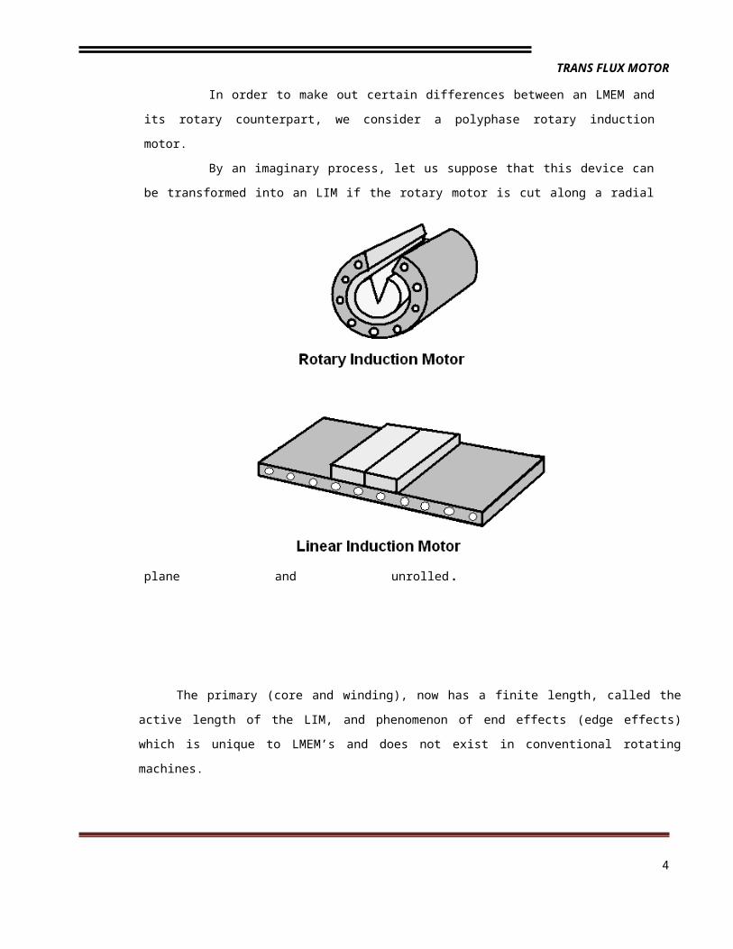
In order to make out certain differences between an LMEM and its rotary
counterpart, we consider a polyphase rotary induction motor.
By an imaginary process, let us suppose that this device can be transformed into an
LIM if the rotary motor is cut along a radial plane and unrolled.
The primary (core and winding), now has a finite length, called the active length of the LIM, and
phenomenon of end effects (edge effects) which is unique to LMEM’s and does not exist in
conventional rotating machines.
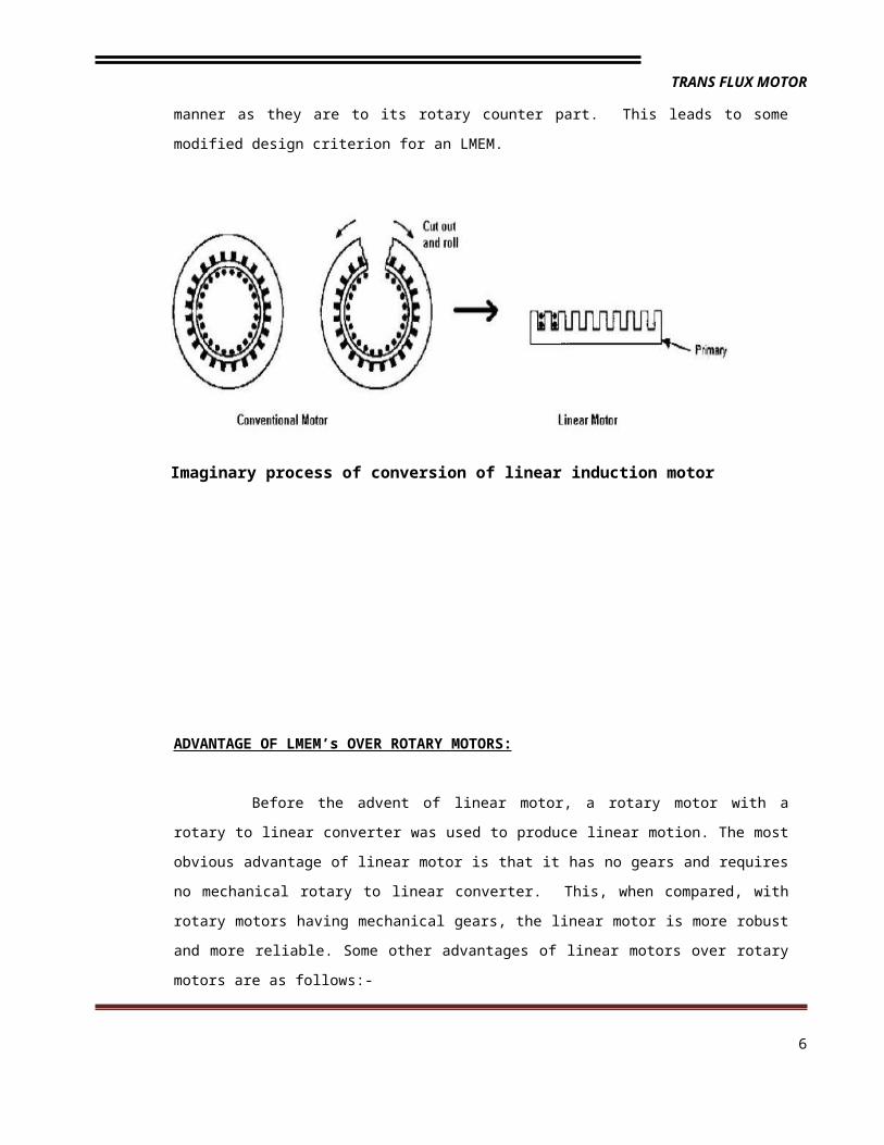
Linear motors potentially have unlimited applications. Linear induction motors
(LIM’s) alone have found application in the following general areas: conveyor systems, material
3
TRANS FLUX MOTOR
handling and storage, people movers, liquid metal pumping, accelerators and launchers,
machine tool operation, airport baggage handling, opening and closing drapes, operation of
sliding doors and low and medium speed trains. For low speed applications both flat and tubular
linear induction motors (TLIM) are suitable. The single-sided linear induction motor (SLIM) is by
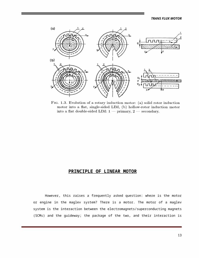
far the most widely used linear motor. A flat or single-sided LIM i.e., a SLIM, is obtained by the
imaginary process of “cutting” and “unrolling” a rotary induction motor. In practice, the primary or
stator of a LIM consists of a rectangular slotted structure formed by a stack of steel laminations.
Within the slots of the primary stack are laid the polyphase windings to produce the linearly
traveling magnetic field, just like the rotating magnetic field in a rotary induction motor, produced
by the polyphase stator windings.
The secondary of the LIM, or rotor, which is an aluminum sheet (or copper), with or
without a solid back iron plate, completes the magnetic circuit and creates the magnetic flux
linkage across the air gap. This in turn induces a voltage on the conductive wall, which
generates an eddy current in the conducting outer layer of the secondary. The interaction
between the eddy current and the changing electromagnetic field generates electromagnetic
thrust on the plate in the longitudinal direction of the motor. A rotating machine can be
considered to be satisfactory if it has high efficiency and good power factor. Because of the end
effects, however, the usual criteria of efficiency and power factor are not applicable to an LMEM
in the same manner as they are to its rotary counter part. This leads to some modified design
criterion for an LMEM.
Imaginary process of conversion of linear induction motor
4
TRANS FLUX MOTOR
ADVANTAGE OF LMEM’s OVER ROTARY MOTORS:
Before the advent of linear motor, a rotary motor with a rotary to linear converter
was used to produce linear motion. The most obvious advantage of linear motor is that it has no
gears and requires no mechanical rotary to linear converter. This, when compared, with rotary
motors having mechanical gears, the linear motor is more robust and more reliable. Some other
advantages of linear motors over rotary motors are as follows:-
High acceleration and deceleration and less wear and tear of the wheels and
track where acceleration and deceleration take place.
Mechanical and electrical protection and the ability to withstand a rough
environment.
Ease in maintenance, repair and replacement.
Ability to exert thrust on the secondary without mechanical components and
contacts, as well as, convenient control of thrust and speed.
Existence of the normal force is advantageous in levitation machines.
5
TRANS FLUX MOTOR
THEORY OF TRANS FLUX MOTOR
A Trans Flux Motor (TFM) is basically a rotating squirrel cage induction motor
opened out flat. Instead of producing rotary torque from a cylindrical machine it produces linear
force from a flat one.It is not a new technology but merely design in a different form. Only the
shape and the way it produces motion is changed. But there are advantages: no moving parts,
silent operation, reduced maintenance, compact size, ease of control and installation
Wherever straight-line motion or reciprocating forces is needed or where unusual
rotary drives are an advantage. Mechanical transmissions are often eliminated, increasing
reliability. The TFM is ideal for applications where space is at premium. Rugged, they can be
used in hazardous environments. Main application area includes transportation, linear elevator,
automatic baggage handling, leisure rider and car crash system.
The principle of operation of a LIM is the same as that of a rotary induction motor. A linear
Induction motor is basically obtained by opening the rotating squirrel cage induction motor and
laying it flat. This flat structure produces a linear force instead of producing rotary torque from a
cylindrical machine. LIMs can be designed to produce thrust up to several thousands of Newtons.
The winding design and supply frequency determine the speed of a LIM.
The basic principle of LIM operation is similar to that of a conventional rotating squirrel-cage
induction motor. Stator and rotor are the two main parts of the conventional three phase rotary
induction motor. The stator consists of a balanced polyphase winding which is uniformly placed in
the stator slots along its periphery. The stator produces a sinusoidally distributed magnetic field in
the air-gap rotating at the uniform speed 2ω/p, with ω representing the network pulsation (related
to the frequency f by ω= 2πf) and p the number of poles. The relative motion between the rotor
conductors and the magnetic field induces a voltage in the rotor. This induced voltage will cause a
6
TRANS FLUX MOTOR
current to flow in the rotor and will generate a magnetic field. The interaction of these two magnetic
fields will produce a torque that drags the rotor in the direction of the field. This principle would not
be modified if the squirrel cage were replaced by a continuous sheet of conducting material.
CLASSIFICATION OF TFM
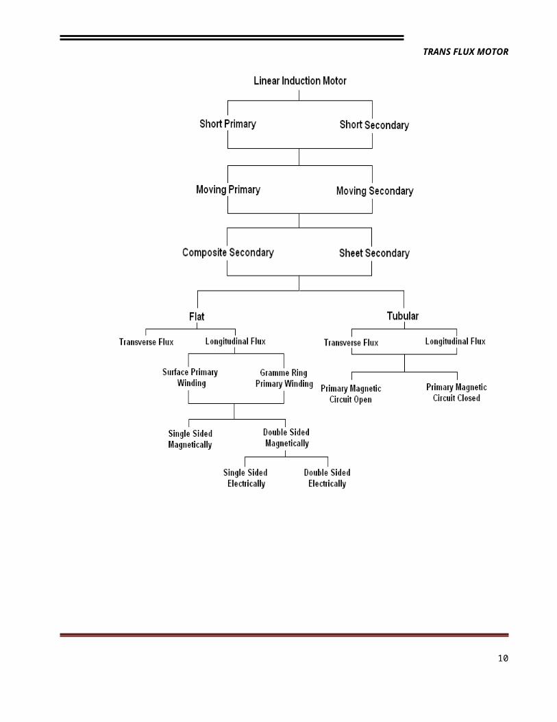
Trans Flux Motors (Linear Induction Motors) are broadly classified into...
7
TRANS FLUX MOTOR
The Linear Induction Machines are also classified according to the application point
of view as Force machines, Power machines and Energy machines.
8
TRANS FLUX MOTOR
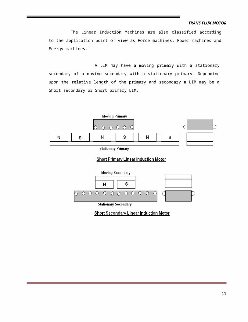
A LIM may have a moving primary with a stationary secondary of a moving secondary
with a stationary primary. Depending upon the relative length of the primary and secondary a
LIM may be a Short secondary or Short primary LIM.
According to the speed of the machine, LIMs are also classified into:
9
TRANS FLUX MOTOR
i) Slow speed propulsion (< 20 m/sec)
ii) Medium speed propulsion (20-70 m/sec)
iii) High speed propulsion (>70 m/sec)
If the LIM has two primaries face to face, then it is called as Double Sided LIM
(DSLIM). If it has only one primary, then it is called as Single Sided LIM (SSLIM).
PRINCIPLE OF LINEAR MOTOR
10
TRANS FLUX MOTOR
However, this raises a frequently asked question: where is the motor or engine in the maglev
system? There is a motor. The motor of a maglev system is the interaction between the
electromagnets/superconducting magnets (SCMs) and the guideway; the package of the two, and their
interaction is what constitutes the motor. Otherwise, there is no standing motor aboard, as in the case
of train locomotive or automobile engine.
In a normal conventional motor, there are two principal parts: the stator, which is stationary; and
the rotor, which can rotate as a result of action from the stator. But whatever the motor, in a maglev
system, it is linearized, meaning that it is opened up, unwound, and stretched out, for as long as the
track extends. Usually, the straightened stators, whether they be long or short, are embedded in the
track, and the rotors are embedded in the electromagnetic system onboard the vehicle; but on
occasion, in some systems, the roles can be reversed. This becomes important in the propulsion
system.
Maglev vehicles are propelled primarily by one of the following options:
1. A Linear Synchronous Motor (LSM): In which coils in the guideway are excited by a three phase
winding to produce a traveling wave at the speed desired.
2. A Linear Induction Motor (LIM): In which an electromagnet underneath the vehicle induces current
in an aluminum sheet on the guideway.
11
TRANS FLUX MOTOR
DESIGN PARTICULARS
The design criterion of the LIM is different from the Induction motor and
implementation of these considerations helps us to get more accurate characteristics.
END EFFECT:
Owing to the existence of factors like the length of primary core a phenomenon
called end effect arises. These are of two types:
(a) Dynamic end effects
(b) Static end effects
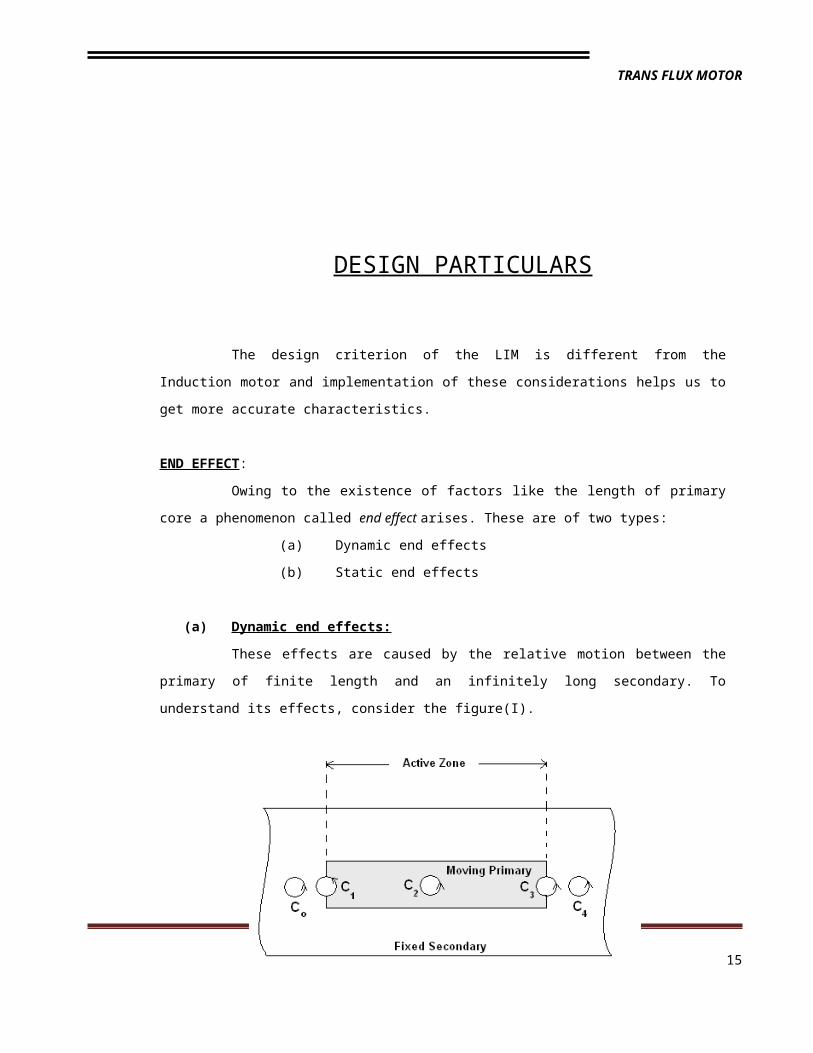
(a) Dynamic end effects:
These effects are caused by the relative motion between the primary of finite length
and an infinitely long secondary. To understand its effects, consider the figure(I).
Figure (i)
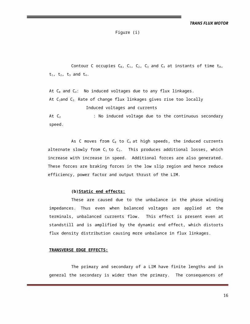
Contour C occupies C0, C1, C2, C3 and C4 at instants of time t0, t1, t2, t3 and t4.
At C0 and C4: No induced voltages due to any flux linkages.
At C1and C3: Rate of change flux linkages gives rise too locally
Induced voltages and currents
At C2 : No induced voltage due to the continuous secondary speed.
12
TRANS FLUX MOTOR
As C moves from C0 to C4 at high speeds, the induced currents alternate slowly from
C1 to C3. This produces additional losses, which increase with increase in speed. Additional
forces are also generated. These forces are braking forces in the low slip region and hence
reduce efficiency, power factor and output thrust of the LIM.
(b)Static end effects:
These are caused due to the unbalance in the phase winding impedances. Thus
even when balanced voltages are applied at the terminals, unbalanced currents flow. This
effect is present even at standstill and is amplified by the dynamic end effect, which distorts flux
density distribution causing more unbalance in flux linkages.
TRANSVERSE EDGE EFFECTS:
The primary and secondary of a LIM have finite lengths and in general the
secondary is wider than the primary. The consequences of the physical features of a LIM are
called transverse edge effects. These currents have a longitudinal component jx and a
transverse component jz. The component jz is the source for these effects. An LIM having
equal secondary and primary widths will show more transverse edge effects than a LIM in which
the secondary is wider.
The transverse edge effect causes:
An increase in secondary resistivity
Tendency towards lateral instability
A distortion in air gap field
A consequent deterioration in the performance of the LIM
SKIN EFFECT:
In a high speed LIM, mechanical constraints require a relatively large distance
between the two primaries of LIM i.e. there is an appreciable distance between the secondary
and primary. When the input frequency is greater than 100 Hz, the current flows only through
the outer part of the conductor. The skin effect may be taken into account by using a correction
factor.
13
TRANS FLUX MOTOR
COMPENSATION OF END EFFECTS :
A variety of methods can be used to compensate end effects in LIM. In general,
compensation is accomplished by using a winding in addition to the main winding of the LIM. The
compensating winding may be located within the active zone of out sided it. In using such a compensating
winding the performance of the secondary can be improved by about 5%.
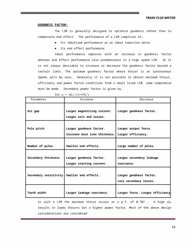
GOODNESS FACTOR:
The LIM is generally designed to optimize goodness rather than to compensate end effect.
The performance of a LIM comprises of…
Its idealized performance as an ideal induction motor
Its end effect performance
Ideal performance improves with an increase in goodness factor whereas end effect
performance also predominates in a high speed LIM. So it is not always desirable to increase or decrease
the goodness factor beyond a certain limit. The optimum goodness factor where thrust is at synchronous
Speed, will be zero. Generally it is not possible to obtain maximum thrust, efficiency and power factor
conditions from a small sized LIM. some compromise must be made. Secondary power factor is given by.
Cos = sGr/(1+s2Gr2)
In such a LIM the maximum thrust occurs at a p.f. of 0.707 . A high sG r results in lower thrusts but a higher
power factor. Most of the above design considerations are considered
14
Parameter Increase Decrease
Air gap Larger magnetizing current.
Larger exit end losses.
Larger goodness factor.
Pole pitch Larger goodness factor.
Increase back iron thickness.
Larger output force.
Larger efficiency.
Number of poles Smaller end effects. Large number of poles.
Secondary thickness Larger goodness factor.
Larger starting current.
Larger secondary leakage
reactance.
Secondary resistivity Smaller end effects. Larger goodness factor.
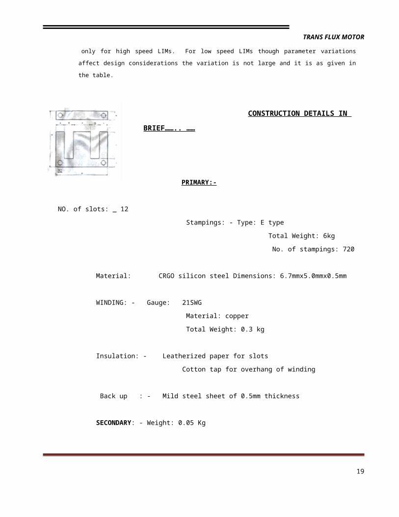
Construction detailsThe design features discussed in design particulars were incorporated in the design of a 30v ,7.5A,3-
phase,12 slot,4-pole,star connected LINEAR INDUCTION MOTTOR PROTOTYPE
A number of such stampings are joined to form the(core) primary of the LIM the prototype
constructed we have used stampings of thicknes 0.5mm and hence to create depth of the core to be 6cm we
have used 120 stampings.
The method of forming the primary of linear induction motor can be easily be understood from the
figure given in the previous page .the layer-2 placed on the layer-1 and layer-2.this process is repeated till the
depth of the core is 6cm .the layers are added In this way in order to reduce the power loss in the core as well
as the leakage flux. then the slots 0 and 13 are cut from odd numbered layers.
The resulting structure of the LIM primary looks like ….
A copper conductor of 21 SWG is used for the windings .A former of right shape is used to over hang
of the winding .It helps in saving o f the winding material and reduction of the leakage flux.
The conductor is wound along the circumference of the former such that there are 60 turns in each
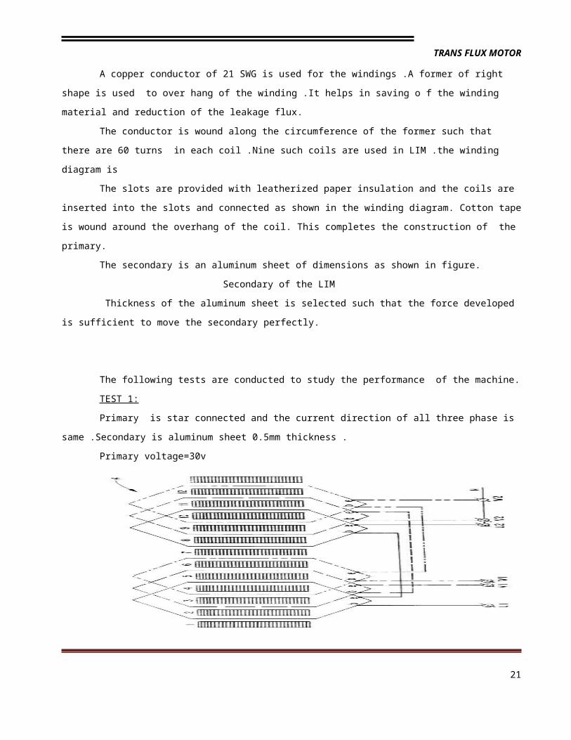
coil .Nine such coils are used in LIM .the winding diagram is
The slots are provided with leatherized paper insulation and the coils are inserted into the slots and
connected as shown in the winding diagram. Cotton tape is wound around the overhang of the coil. This
completes the construction of the primary.
The secondary is an aluminum sheet of dimensions as shown in figure.
Secondary of the LIM
16
TRANS FLUX MOTOR
Thickness of the aluminum sheet is selected such that the force developed is sufficient to move the
secondary perfectly.
The following tests are conducted to study the performance of the machine.
TEST 1:
Primary is star connected and the current direction of all three phase is same .Secondary is
aluminum sheet 0.5mm thickness .
Primary voltage=30v
Primary current=7A
RESULT:- The secondary is self- started and the force developed is enough to cause propulsion of
the secondary
REASON :-
Power induced in the secondary Bm2
Weight to be moved t
Flux density and the thickness of the secondary are sufficient to develop significant force in the
secondary
TEST 2:-
Primary is star connected and the current direction in one of the phases is reversed.
Secondary is Aluminum sheet of 0.5mm thickness
Primary voltage=30v
Primary current=7A
RESULT:-
There is no movement in secondary.
REASON:-
The reversal one phase produces only one pole through out the length of machine.
Due to the absence of alternative pole change induced currents in the secondary will be zero .it makes the
propulsion force of the secondary zero
17
TRANS FLUX MOTOR
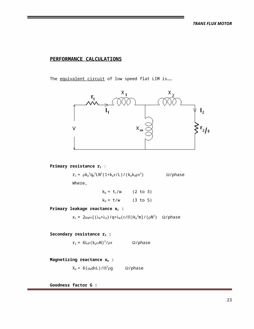
PERFORMANCE CALCULATIONS
The equivalent circuit of low speed flat LIM is……
Primary resistance r1 :
r1 = kp2qm
2LN2(1+kp/L)/(kpkd2) /phase
Where,
kp = tc/w (2 to 3)
kd = t/w (3 to 5)
Primary leakage reactance x1 :
x1 = 20[(0+d)/q+0(/)kp2m]/(N2) /phase
Secondary resistance r2 :
r2 = 6L(kpN)2/ /phase
Magnetizing reactance xm :
Xm = 6(0dL)/2g /phase
Goodness factor G :
G = Xm/r2
= 20ft/(prg)
18
TRANS FLUX MOTOR
In a three phase double sided LIM, (on per phase per side basis) the following
relationships give the performance characteristics of the motor.
Input power = V1I1 Cos 1
Primary copper loss = I1r1
Developed power = (1- s)( V1I1 Cos 1- I1r1 )
Developed force = (Developed power)/u
Secondary copper loss = s( V1I1 Cos 1 - I1r1 )
Where s = slip
u = LIM speed
Cos 1 = Input power factor
Effect of Aluminum thickness on the performance parameters
The effect of varying the thickness of the aluminum sheet on the rotor of SLIM on its
performance, from 1mm to 5mm in steps of 1mm is as shown below. The goodness factor of a SLIM
is given by equation above, where the thickness of aluminum sheet on the rotor, d, plays a
significant role in the performance. It can be seen that, the thicker the secondary, the larger the
goodness factor. Also, thicker aluminum sheet will increase the magnetic air-gap which is
undesirable. For nonferrous secondary, the thickness must be small but large enough to withstand
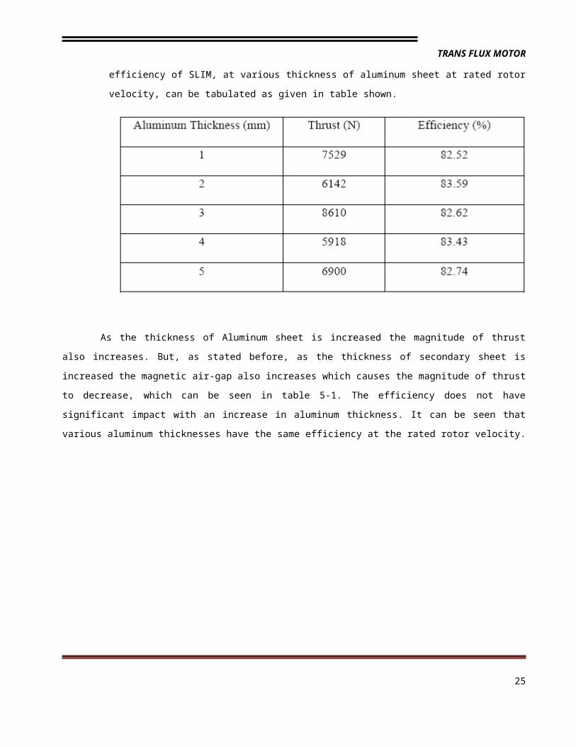
the forces present on the rotor. The performance parameters thrust and efficiency of SLIM, at
various thickness of aluminum sheet at rated rotor velocity, can be tabulated as given in table
shown.
19
TRANS FLUX MOTOR
As the thickness of Aluminum sheet is increased the magnitude of thrust also increases. But, as
stated before, as the thickness of secondary sheet is increased the magnetic air-gap also increases which
causes the magnitude of thrust to decrease, which can be seen in table 5-1. The efficiency does not have
significant impact with an increase in aluminum thickness. It can be seen that various aluminum thicknesses
have the same efficiency at the rated rotor velocity.
Figure1 Figure21.Effect of aluminum thickness on the thrust of SLIM plotted against rotor
velocity at a rated slip of 10%, a desired rotor velocity of 15.5 m/s and target
20
TRANS FLUX MOTOR
thrust of 8611N.
2.Effect of varying Aluminum thickness on efficiency of SLIM plottedagainst rotor velocity at a rated slip of 10%, a desired rotor velocity of 15.5 m/s
and target thrust of 8611N.
From Fig 1 and 2, it can be seen that the magnitude of thrust at rated velocity is maximum when the
thickness of aluminum is 3mm at a reasonable value of efficiency. The actual thrust developed is 8610N at an
efficiency of 82.6%for the SLIM operating at 10% slip and target thrust of 8611N as shown in table 4-8. Hence,
a value of 3mm is chosen as the best value which yields maximum thrust at a reasonable efficiency.
As the thickness is increased beyond a certain value, the magnetic air-gap increases, which will reduce the flux
linkage between the currents produced in the stator and the rotor conductor. Hence, an optimum value must be
chosen for the thickness of the secondary conductor, which is 3mm for this particular design.
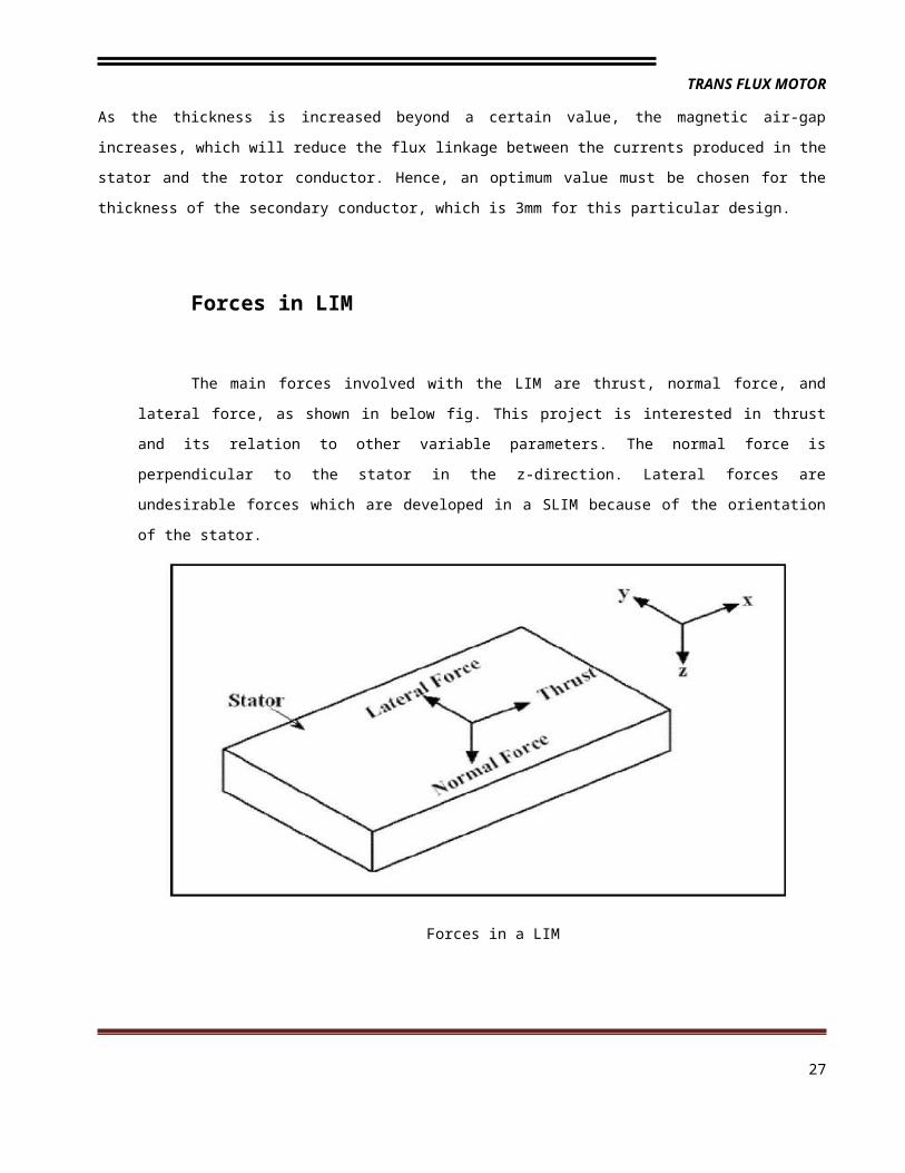
Forces in LIM
The main forces involved with the LIM are thrust, normal force, and lateral force, as shown in
below fig. This project is interested in thrust and its relation to other variable parameters. The normal
force is perpendicular to the stator in the z-direction. Lateral forces are undesirable forces which are
developed in a SLIM because of the orientation of the stator.
21
TRANS FLUX MOTOR
Forces in a LIM
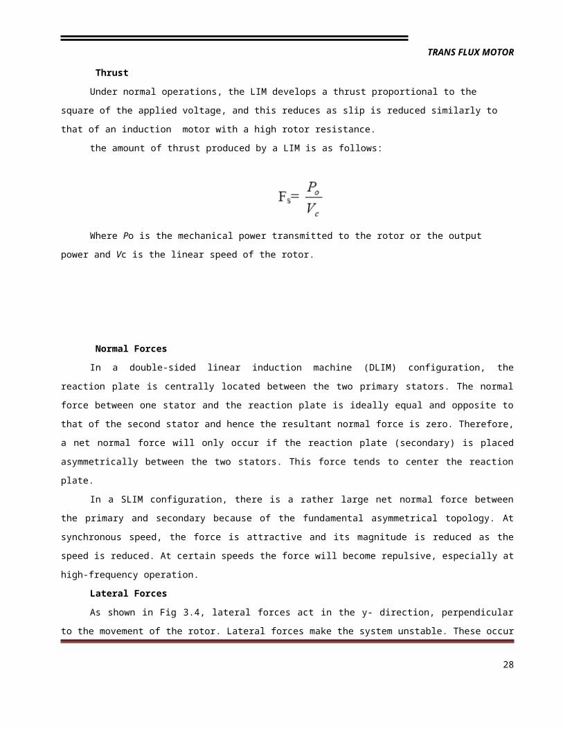
Thrust
Under normal operations, the LIM develops a thrust proportional to the square of the applied voltage,
and this reduces as slip is reduced similarly to that of an induction motor with a high rotor resistance.
the amount of thrust produced by a LIM is as follows:
Where Po is the mechanical power transmitted to the rotor or the output power and Vc is the linear
speed of the rotor.
Normal Forces
In a double-sided linear induction machine (DLIM) configuration, the reaction plate is centrally located
between the two primary stators. The normal force between one stator and the reaction plate is ideally equal
and opposite to that of the second stator and hence the resultant normal force is zero. Therefore, a net normal
force will only occur if the reaction plate (secondary) is placed asymmetrically between the two stators. This
force tends to center the reaction plate.
In a SLIM configuration, there is a rather large net normal force between the primary and secondary
because of the fundamental asymmetrical topology. At synchronous speed, the force is attractive and its
magnitude is reduced as the speed is reduced. At certain speeds the force will become repulsive, especially at
high-frequency operation.
Lateral Forces
As shown in Fig 3.4, lateral forces act in the y- direction, perpendicular to the movement of the rotor.
Lateral forces make the system unstable. These occur due to the asymmetric positioning of the stator in a LIM.
Generally, small displacements will only result in very small lateral forces. These forces are a matter of concern
in high frequency operation (>>60Hz) where they increase in magnitude. A set of guided mechanical wheel
tracks is sufficient to eliminate a small lateral force.
Applications
Sliding Doors Sewage Distributors Automated
22
TRANS FLUX MOTOR
Warehousing
Aluminium Can Propulsion Crane DrivesStage/Curtain Movement
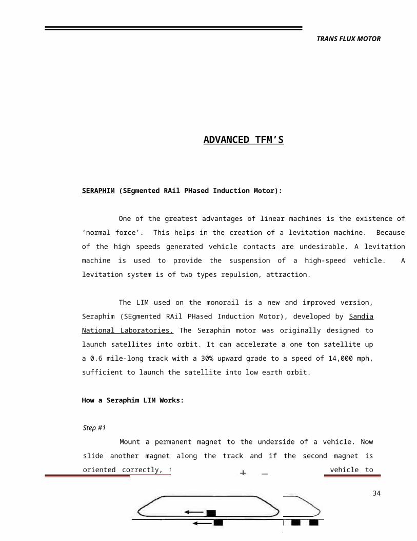
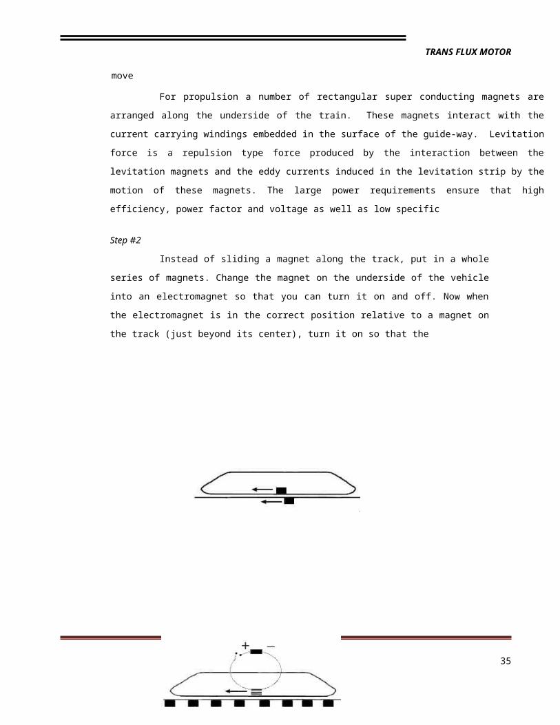
Instead of sliding a magnet along the track, put in a whole series of magnets.
Change the magnet on the underside of the vehicle into an electromagnet so that you can
turn it on and off. Now when the electromagnet is in the correct position relative to a magnet
on the track (just beyond its center), turn it on so that the
magnets repel and the vehicle is pushed along. Turn the electromagnet off before it gets too
close to the next magnet (or it will brake the vehicle). Let the vehicle run on just past the next
magnet, and then pulse the electromagnet again so that the vehicle continues moving
forward. Continue this process. To brake the vehicle, pulse the electromagnet just before it
reaches a magnet on the track.
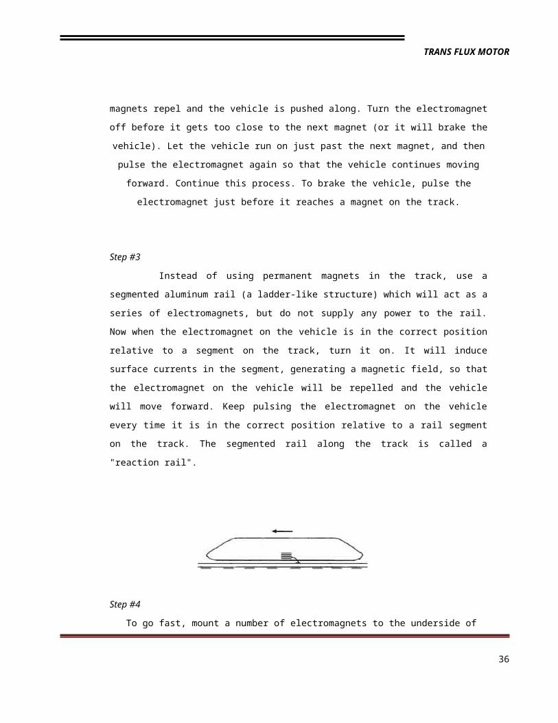
Step #3
Instead of using permanent magnets in the track, use a segmented aluminum rail
(a ladder-like structure) which will act as a series of electromagnets, but do not supply any
power to the rail. Now when the electromagnet on the vehicle is in the correct position relative
to a segment on the track, turn it on. It will induce surface currents in the segment, generating
a magnetic field, so that the electromagnet on the vehicle will be repelled and the vehicle will
move forward. Keep pulsing the electromagnet on the vehicle every time it is in the correct
position relative to a rail segment on the track. The segmented rail along the track is called a
"reaction rail".
28
TRANS FLUX MOTOR
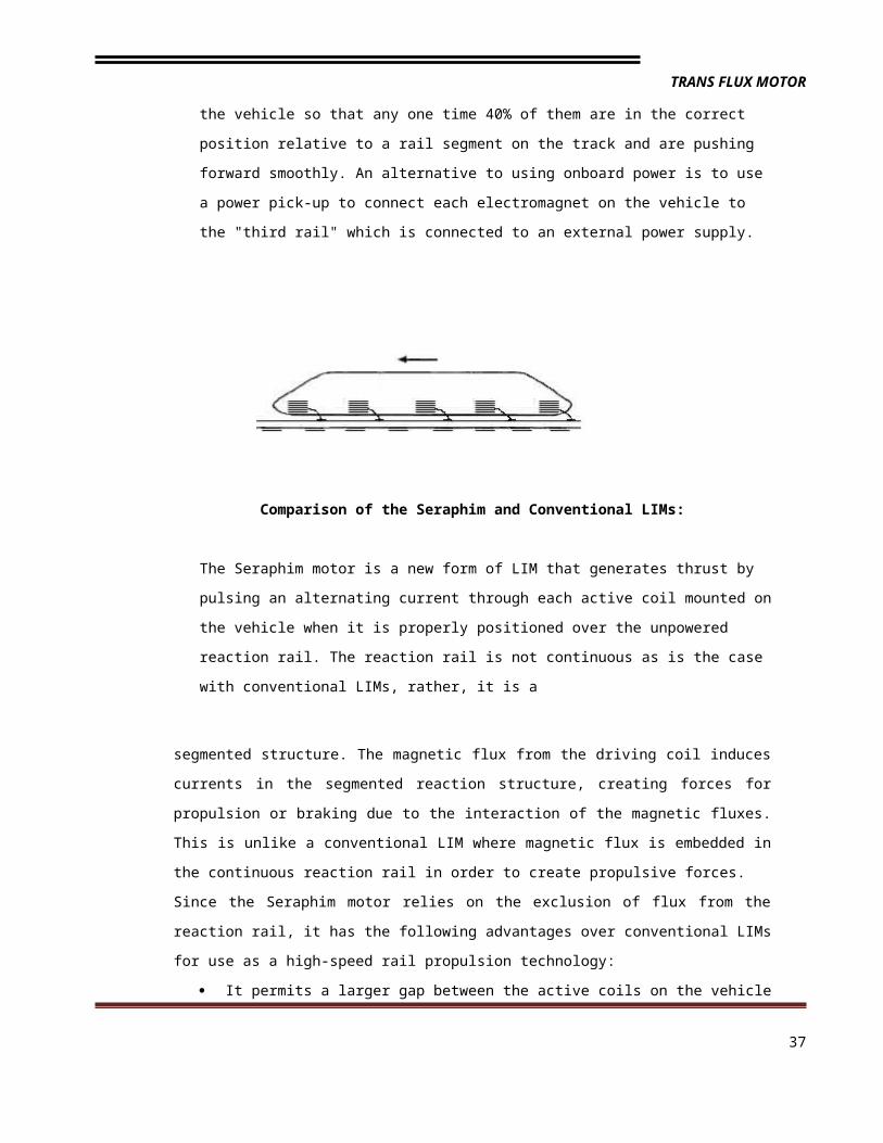
Step #4
To go fast, mount a number of electromagnets to the underside of the vehicle so that any
one time 40% of them are in the correct position relative to a rail segment on the track
and are pushing forward smoothly. An alternative to using onboard power is to use a
power pick-up to connect each electromagnet on the vehicle to the "third rail" which is
connected to an external power supply.
Comparison of the Seraphim and Conventional LIMs:
The Seraphim motor is a new form of LIM that generates thrust by pulsing an alternating
current through each active coil mounted on the vehicle when it is properly positioned
over the unpowered reaction rail. The reaction rail is not continuous as is the case with
conventional LIMs, rather, it is a
segmented structure. The magnetic flux from the driving coil induces currents in the
segmented reaction structure, creating forces for propulsion or braking due to the interaction
of the magnetic fluxes. This is unlike a conventional LIM where magnetic flux is embedded in
the continuous reaction rail in order to create propulsive forces.
Since the Seraphim motor relies on the exclusion of flux from the reaction rail, it has the
following advantages over conventional LIMs for use as a high-speed rail propulsion
technology:
It permits a larger gap between the active coils on the vehicle and the reaction rail on
the guideway, up to 1", and perhaps larger, which improves ride quality and relaxes
guideway tolerances, significantly reducing construction and maintenance costs.
Very low magnetic drag is induced in the reaction rail (assuming proper motor
control), which improves motor efficiency.
It is smaller, lighter, and more compact than a conventional LIM, and costs
29
TRANS FLUX MOTOR
significantly less to build and operate.
The efficiency of the motor increases with speed.
The power of the Seraphim motor is limited only by the power available, the frequency of
pulsing relative to the required energy input necessary for a desired speed of operation, and
by the maximum acceleration/deceleration forces that can be comfortably accommodated by
passengers.
The bottom line is:
The Seraphim motor may be the fastest motor ever developed.
At the same time, it is not complex and hence it is relatively inexpensive to
manufacture and maintain.
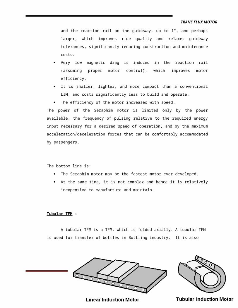
Tubular TFM :
A tubular TFM is a TFM, which is folded axially. A tubular TFM is used for transfer of
bottles in Bottling industry. It is also used for transporting molten metals. Here the molten
metal acts as the moving secondary. Presently, the same principle of tubular induction motor
is used in high - speed transportation. Research is going on to develop and implement this
principle in various other fields.
APPLICATION OF TFM
Traditionally, linear motion wherever required has been produced using a rotary motor in conjunction
with a linear converter. The emergence of linear motors has changed this scenario entirely. Linear motion could
be easily obtained with the employment of a linear motor, with out the additional hindrance of a converter and
its accompanying defects like mechanical, abrasion, friction, wear and tear. having the property of high
acceleration and deceleration, the linear motors also have the ability to exert thrust on the secondary without
mechanical contacts, thus making their repair and maintenance easier.
30
TRANS FLUX MOTOR
From an applications standpoint TFM’s can be divided into force machines, power machines and energy
machines. force machines are short duty machines that are used in low speed applications. power machines
are medium or high-speed machines used as continuous duty machines. energy machines are used whenever
thrust or impact is required as the output. the following is the summary of some of the most common
applications of a TFM.
High Speed Ground Transportation (HSGT):
Medium and high-speed applications of linear electric machines are mainly propulsion
and levitation systems for ground transportation. speeds nearly reaching 560 mph could be easily achieved
with this TFM’s whereas rotary motors, due to their adhesive effects and other mechanical considerations,
cannot be used at such high speeds.
For speeds at which mechanical contact is undesirable it has been proposed to use a levitation
machine for a magnetic suspension system. for both propulsion and suspension of HSGT test vehicles having
linear motors(DSLIM’s) have been designed and built in U.S, U.K, Germany, France and Japan.
Low speed applications:-
A low speed TFM can be used in the tensioning of an aluminum strip for cooling. the TFM
thrust against the motion of the strip enables tension to be applied without contact. thus avoiding scratching of
the surface. Typically, nine DSLIM’s are used and the aluminum foil of strip constitutes the secondary. for the
application the aluminum foil is in between 0.5 and 1.4 mm thick and each TFM has a continuous thrust rating
of 60 N.
31
TRANS FLUX MOTOR
Another application of a TFM is a linear disc motor. this is used in achieving the
traction motion of an overhead crane. The low shaft speeds of 150-200 rpm enables a single gear reduction of
4:1 between the motor and the crane wheels to be fitted.
The linear disc motor also can be used in marine ship propulsion. TFM’s are also used in
conveyors. For such a horizontal application carrying steel stock sections SLIM primaries placed at intervals,
depending on the length of the material. for a typical coal-carrying conveyor a number of TFM primaries may
be spaced about 3m apart.
The working scale model of an electromagnetic arrestor system which may someday replace winches
and pulleys that govern the arresting cable on an aircraft carrier’s deck.
A flat linear motor can be used as an automatic door operator. a flat TFM can serve
as actuators in mechanical handling and for pipe lifting beam in steel works. other applications of TFM’s range
from turntables to aerodynamic disc-reading heads in a computer, and from induction stirrers for molten metals
to shuttle propulsion and package winding in the textile industry.
Energy TFM:
TFM, as an energy machine, was first used to launch an aircraft. this machine was called an
electroplate. Primary winding was mounted on a carriage on the secondary consisted of winding in slots in a
ferromagnetic structure. the motor is very similar to an SLIM with an extended secondary.
32
TRANS FLUX MOTOR
Other application of TFM’s includes accelerators for very high velocity projectiles and actuators in
high voltage circuit breakers. TFM’s have also been used to simulate the conditions of a car crash. TFM is
capable of accelerating vehicles weighing as much as 10,000 lb. to any speed up to 40 mph has been used as
prime mover to drive the vehicle. the aluminum alloy reaction rail or secondary, stands vertically in a pit. the
primary has an inverted u frame containing two winding blocks. current is fed to the primary by means of
carbon brushes that run along the collector rails.
Another application of TFM’s is for the purpose of impact extrusion. because they are simple in
construction and very reliable they will find more and more applications in situations in which mechanical gears
and rotary to linear converters is undesirable.
MAGNETIC LEVITATION
33
TRANS FLUX MOTOR
Levitation means “to rise and hover in air “. In Magnetic levitation the main source for levitation is a
magnet. When a permanent magnet sweeps across a conducting ladder horizontal tractive force and vertical
force should be the result. But in case, the magnet speed is slow then the vertical force gets cancelled. So, the
main requisite for the system to be levitated is that the magnet should travel at high speeds.
At high speeds the instantaneous position of the magnet is to be concerned for the result of
levitation, because the delay due the conductor inductance plays the vital role, as a result current in the
conductor reaches its maximum value in a fraction of a second (Δt) after voltage reaches its maximum value
Hence, by the time current in conductor reaches its maximum value, the center of the magnet is already ahead
of the respective conductor by a distance=v(Δt) where v is the magnet velocity. Here comes the main
application of trans flux motors, as a propelling device.
EARLIER TECHNOLOGY USING SUPERCONDUCTORS:
The fundamental property of exclusion of magnetic flux from a superconductor and the consequent
levitation of superconducting bodies above magnetic material is the main principle behind magnetic levitation
using superconductors. But levitation caused by using super conducting coils to generate their magnetic field,
require expensive, cryogenic cooling systems. These maglev systems also require complicated feedback
circuits to prevent disastrous instabilities in their high-speed operation.
NEW TECHNOLOGY:
A new technology, called inductrack, is developed for magnetic levitation . It is fundamentally much
simpler in design and operation (requiring no super conducting coils or stability control circuits), potentially
much less expensive, and more widely adaptable than other maglev systems.
The Livermore team has developed a maglev design call inductrack, which uses an arrangement of
permanent magnets in a pattern called the HalBach array. Klaus Halbach, a retired researcher from Lawrence
Berkeley National Laboratory, invented the array for use in a particle accelerato.
The array combines magnets to create a periodic field that is alternatively vertical and horizontal.
The interaction causes the magnetic fields to concentrate on one surface, while canceling it on the opposite.
34
TRANS FLUX MOTOR
According to Richard Post, the Livermore physist who invented inductrack, it is this concentration that
makes the use of permanent magnets practical. The system allows a 50-lb load to be lifted with only one pound
of magnet.
Inductrack uses permanent magnets of neodymium, a rare earth, combined with iron and boron on
the underside of the vehicle, which rides in a guide way, lined with inductive coils. As long as the vehicle keeps
moving, the permanent magnets induce magnetic fields around the coils, and the vehicle levitates.
The “Inductrack” is an array of permanent magnets on the moving object, plus a “track” composed
of shorted electrical circuits. This system can levitate a mass that approaches the theoretical limit of force
exerted by array’s magnetic field. The system also is energy efficient at high speeds, with typical Lift-to-drag
ratios of order 200:1
Two keys to the performance of the inductrack:
(1) The use of Halbach arrays on the moving object
(2) The use of a “track” composed of close-packed circuits, excited inductively by the moving
arrays.
Halbach arrays are ideally suited for maglev applications since they create a sinusoidal periodic field below
the array, while canceling the field above the array. At high speeds, induced current lags induction by nearly 90
degrees, maximizing the lift and minimizing the drag (which varies inversely with speed).
The magnets are rare earth (Neodymium Iron Boron), and are square or rectangular in shape. They
are arranged in an alternating pattern, and end up concentrating all of the magnetic field on one side of the
array. The external fields on one side of these magnets, are opposed or repulsive and end up canceling each
other, while the fields on the opposite side are attractive and end up reinforcing each other. This arrangement
then results in this asymmetrical field, where one side of the array has a large field, and the other has almost
none.
35
TRANS FLUX MOTOR
WORKING OF MAGLEV VEHICLEBasically the construction depends on 3 different working forces.
· PROPULSION FORCE
· LEVITATING FORCE
· LATERAL GUIDING FORCE
PROPULSION FORCE:
This is a horizontal force which causes the movement of train. It
requires 3 parameters.
• Metal coil lining, a guide way or track.
.Large electric power supply
• Large magnet attached under the vehicle.
PRINCIPLES OF LINEAR MOTOR
Its principle is similar to induction motor having linear stator and flat
rotor. The 3-phase supply applied to the stator produces a constant
speed magnetic wave, which further produces a repulsive force.
Maglev vehicles are propelled primarily by one of the following three options:
1.A linear synchronous motor (LSM) in which coils in the guide way are excited by a three phase winding to
produce a traveling wave at the speed desired; Trans Rapid in Germany employs such a system.
2. A Linear Induction Motor (LIM) in which an electromagnet underneath the vehicle induces current in an
Aluminum sheet on the guide way.
3. A reluctance motor is employed in which active coils on the
Vehicle is pulsed at the proper time to realize thrust.
LEVITATING FORCE:
The levitating force is the upward thrust which lifts the vehicle in the air.
There are 3 types of levitating systems
1. EDS system
2. EMS system
3. INDUCTRACK system
36
TRANS FLUX MOTOR
Levitating force is produced due to the eddy current in the conducting ladder by the electromagnetic interaction.
At low speed the force due to induced poles cancel each other. At high speed a repulsive force is taken place
as the magnet is shifted over a particular pole.
1. EDS SYSTEM:
In EDS both the rail and the train exert a magnetic field, and the train is levitated by the repulsive force
between these magnetic fields. At slow speeds, the current induced in these coils and the resultant magnetic
flux is not large enough to support the weight of the
train. For this reason the train must have wheels or
some other form of landing gear to support the train
until it reaches a speed that can sustain levitation.
Onboard magnets and large margin between rail and
train enable highest recorded train speeds (581
km/h).This system is inherently stable. Magnetic
shielding for suppression of strong magnetic fields and
wheels for travel at low speed are required. It can’t
produce the propulsion force. So, LIM system is
required.
37
TRANS FLUX MOTOR
2. EMS SYSTEM:
Maglev concepts using electro -magnetic
suspension employ attractive forces. Magnetic fields
inside and outside the vehicle are insignificant; proven,
commercially available technology that can attain very
high speeds (500 km/h ; no wheels or secondary
propulsion system needed. The separation between the
vehicle and the guide way must be constantly monitored
and corrected by computer systems to avoid collision due
to the unstable nature of electromagnetic attraction.
3. INDUCTRACK SYSTEM:
The inductrack guide way would contain two rows of tightly packed levitation coils, which would act as
the rails. Each of these “rails” would be lined by two Halbach arrays carried underneath the maglev vehicle:
one positioned directly above the “rail” and one along the inner side of the “rail”. The Halbach arrays above the
coils would provide levitation while the Halbach arrays on the sides would provide lateral guidance that keeps
the train in a fixed position on the track.
The track is actually an array of electrically-shorted circuits containing insulated wire. In one design,
these circuits are aligned like rungs in a ladder. As the train moves, a magnetic field repels the magnets,
causing the train to levitate. There are two inductrack designs. Inductrack I and II. Inductrack I is designed for
high speeds, while inductrack II is suited for slow speeds. Inductrack trains could levitate higher with greater
stability. As long as it’s moving a few miles per hour, an inductrack train will levitate nearly an inch above the
track. A greater gap above the track means that the train would not require complex sensing systems to
maintain stability. Permanent magnets had not been used before because scientists thought that they would
not create enough levitating force. The inductrack design bypasses this problem by arranging the magnets in a
Halbach array. The magnets are configured so that the intensity of the magnetic field concentrates above the
array instead of below it which generates higher magnetic field.
38
TRANS FLUX MOTOR
The inductrack II design incorporates two Halbach arrays to
generate a stronger magnetic field at lower speeds. Dr. Richard post at
the Livermore National Laboratory in California came up with this
concept in response to safety and cost concerns. The prototype tests
caught the attention of NASA, which awarded
a contract to Dr.post and his team to explore the possibility of using the
inductrack system to launch satellites into orbit.
LATERAL GUIDING FORCE:
Guidance or steering refers to the sideward forces that are required to make the vehicle follow the guideway.
The necessary forces are supplied in an exactly analogous fashion to the suspension forces, either attractive or
repulsive. The same magnets on board the vehicle, which supply lift, can be used concurrently for guidance or
separate guidance magnets can be used.
It requires the following arrangements:
· Guideway levitating coil
· Moving magnet
Linear induction motor (LIM) in magnetic levitation
The High Speed Surface Transport (HSST) system is propelled by linear induction motor. The HSST
primary coils are attached to the carriage body and the track configuration is simple, using the steel rails and
aluminum reaction plates. The HSST levitation system uses ordinary electromagnets that exerts an attractive
force and levitate the vehicle. The electro-magnets are attached to the car, but are positioned facing the under
side of the guide way’s steel rails. They provide an attractive force from below, levitating the car.
39
TRANS FLUX MOTOR
‘ This attractive force is controlled by a gap sensor that measures the distance between the rails and
electromagnets. A control circuit continually regulates the current to the electro-magnet , ensuring that the gap
remains at a fixed distance of about 8 mm, the current is decreased. This action is computer controlled at 4000
times per second to ensure the levitation.
A s shown in figure, the levitation magnets and rail are both U shaped (with rail being an inverted U).
The mouths of U face one another. This configuration ensures that when ever a levitational force is exerted, a
lateral guidance force occurs as well. If the electromagnet starts to shift laterally from the center of the rail, the
lateral guidance force is exerted in proportion to the extent of the shift, bringing the electromagnet back into
alignment. The use of an electro-magnetic attractive force to both levitate and guide the car is a significant
feature of HSST the system We can visualize an HSST linear motor as an ordinary electric induction motor that
has been split open and flattened. This of linear motor has recently been used in various fields the fig illustrates
in the HSST, the primary side coils of motor are attached to the car body in the secondary side reaction plates
are installed along the guide way .this component acts as induction motor and ensures both propulsion and
breaking force without any contact between car and guide way. This system a car mounted primary linear
induction system. The ground side requires only a steel plate backed by an aluminum or copper plate, meaning
that the rail source is simple.
One of the HSST’s unique technical features is modules that correspond to the bogies on connectional
rolling stock. Figure shows each consist primarily of a member of electromagnets for levitation guidance, a
linear motor for propulsion and braking, and a hydraulic break system. The two modules on the left and right
sides of the car connected beams and this unit is called levitation bogie because the levitation bogies run the
entire length of the car, the load car and load on guide way are spread out and the advantages of magnetic
levitation can be fully exploited.
Characteristics of LIM
In most vehicular propulsion systems, provision must be made for increasing the power when the
demand increases due to acceleration, a heavier load, increased drag, headwinds, or climbing a hill. In the
case of an automobile, this is done through manipulation of both the accelerator and the transmission. But all of
this is accomplished automatically when an LIM is used. Whenever more power is needed, the moving magnet
begins to lag further behind the stationary one; this results in an immediate increase in thrust. No separate
control is needed.
40
TRANS FLUX MOTOR
Moreover, when an LIM-powered vehicle descends a steep hill or decelerates into a station, the
moving motor advances to a position where it leads the stationary one. Under these conditions, the motor
performance is shown in the left half of Figure. This automatically results in the production of electrical
energy which is fed back into the system with a frequency and phase coherent with the line voltage. In other
words, LIM’s are automatically regenerative.
CASE STUDY-1
MAGLEV TRAINS
When the train is at rest, no levitation occurs. As soon as the train exceeds a transitional speed,
which is achieved by means of a LIM, the arrays induce sufficient currents in the track’s inductive coils to
levitate the train. The train is consistently stable while levitated and flying over the track. The Inductrack theory
also shows levitation of loads approaching 50 times the weight of the magnets, important for reducing the cost
relative to maglev vehicles.
41
TRANS FLUX MOTOR
The electromagnetic drag associated with Inductrack becomes small at high speeds, an auxiliary
power source would be needed to maintain the train’s high speed against aerodynamic drag. The amount of
power needed depends on the weight of the vehicle and its maximum speed. If the external drive power ever
fails , or when the train arrives at a station, the train would simply coast to a stop. In the sense , Inductrack is a
true fail-safe system. Halbach array offers other benefits besides levitation. Because its magnetic fields cancel
out above the magnets, there is no worry about magnetic fields affecting passengers.
An Inductrack system would cost more to build than conventional rail systems, it should be less
expensive than maglev trains using super conducting coils. Inductrack achieves speeds of 350 kilometers per
hour and up and lower energy costs, wheel and rail wear, propulsion maintenance and noise levels.
CASE STUDY-2
SPACE APPLICATIONS:
NASA is interested in maglev technology to help launch rockets at sharply reduced costs. as
conceived, a track would use a reusable launcher to propel a rocket up a ramp to almost mach 1 speeds before
the rocket’s main engines fire. this technology reduces about 30% of the weight of the launch vehicle.
The design goals include a 30% reduction in manning. 20% reduction in life cycle cost, 20%
improvement in operational availability, and up to 50% reduction in installed size and weight when compared
with current steam catapults.
42
TRANS FLUX MOTOR
NASA envisions a track a mile and a half long on which a winged craft would ride on a sled that
would be magnetically levitated and propelled at an acceleration of 2 gs until it reached a speed of 400mph.
the magnetic shuttle would go from zero to 400 in about 9 ½ seconds and disengage, when first stage rockets
would take over.
NASA calculates that using the maglev system, instead of fuel onboard, for initial acceleration
con reduce the weight of an orbit-bound vehicle by 20%.
Foster-miller’s maglev launch system for NASA uses two sets of windings on the track. one set
forms the stator that propels the vehicle, and other windings in which magnetic fields are passively induced,
levitate the vehicle above the track.
The levitation system, called “null flux,” places a system of induction coils wound as figure 8s
in the track. if the vehicle has a magnetic field that passes directly through the centers of the 8s, there is no net
flux. but if the vehicle’s field passes between the 8s slightly below their center, it induces an opposing
magnetic field that lifts the car.
The propulsion system uses optical sensors on the track to tell when the car is coming and to
turn on the magnetic coils in the appropriate region to accelerate the vehicle.
43
TRANS FLUX MOTOR
The inductrack can work with many forms of propulsion. the version being built for NASA
uses pulsed drive coils interleaved with levitation coils. 95%of the track holds levitation coils that work with the
horizontal component of the halbach array’s magnetic field. The drive coils, occupying as little as 5% of the
track, work with the vertical component of the field. The vehicle moves forward as pulsed currents are sent to
the drive coils along the track.
Proponents of maglev say the potential for savings over time is substantial, not only because
of the difference in weight, but also because a magnetic levitation leaves the first stage of propulsion intact on
the ground, waiting for the next flight. Buchman at the Marshall center has come up with an informal estimate
that accelerating a 120,000-lb. launch vehicle from a maglev track could use an equivalent of as little as $75
worth of electricity, at current, local market rates.
the goal of using magnetic levitation is to help reach a target of reducing the cost of
launching payload from the present $10,000 a pound to less than $1,000, and perhaps eventually to $200 a
pound or so.
As magnifier would bring some changes to a space launch. there would be no countdown for
a maglev lifter launch, for instance. a launch vehicle could leave just like a jet airliner, one every hour. the
launch using the maglev track would start by accelerating in a horizontal direction, rather than vertical, and
when it disengaged from the levitating shuttle the launch vehicle would have to pull up, like an airplane. the
familiar launch towers at Cape Canaveral would become a thing of the past. in their place would be a couple of
kilometers or so of track.
CONCLUSION
A working model of a 4 – pole, 12 – slot, 3 – phase Trans Flux Motor was fabricated
in the laboratory. Tests were performed on it especially those relating to the variation of force
44
TRANS FLUX MOTOR
developed with respect to the thickness of the secondary (aluminum sheet). Iron filings
(cleaned in petrol) were used to determine the shape of the flux lines leaving the primary.
Several applications and case studies of the Trans Flux Motor are discussed. One
of the latest applications of low speed TFM’s is the phenomenon of impact extrusion where
impact is the output. TFM’s are also being developed for the purpose of shuttle launching and
many other applications are paving their way into light. Lim ‘s are being developed for the
purpose of high speed transportation, shuttle launching and many other applications, are paving
their own to light. One day the familiar launch towers at Cape Canaveral would become a thing
of past. In that place there would be a couple of kilometers or so of track. Lim, the Trans Flux
Motor (TFM) becomes The Future Machine.
45
TRANS FLUX MOTOR
BIBLIOGRAPHY
Special Induction Motors – Prof. E. R. Laithewaite
Inductrack – Klaus Hallbach
Design of Trans Flux Motor – www.baldros.com
www.forceengineering.com
www.maglevquicklinks.com
U.S. Department of transportations(Federal transit sadministration). Low speed maglev Technology Development Program . Final Report, FTA-CA-26-7025-02.1 , March 2002.
R. F. Post, D. D. Ryutov, .The Inductrack: A Simpler Approach to Magnetic Levitation,. I.E.E.E,Transactions on Applied Superconductivity, 10, 901 (2000)