66
www.americanradiohistory.com

Coning Next Month
In December, we take another look at microphones. Although new design con- cepts may not come along at the same pace as in console design, still, there is
always one more applications concept for us to try out. New ideas are devel- oped, and old ones are rediscovered, and you can keep up with it all by reading the December issue of db -The Sound Engineering Magazine.
Spanning several generations, a family portrait of recorded discs. In the fore- ground, the new Philips Compact Digital Disc is shown in perspective with an an- tique gramophone.
THE SOUND ENGINEERING MAGAZINE
NOVEMBER 1979 VOLUME 13. NUMBER 11
EDITORIAL
A db SPECIAL REPORT: EDUCATION AND AUDIO
John M. Woram
SCHOOL DAYS AT MCI Irwin J. Diehl
SPECTRUM ANALYSIS ON A PERSONAL COMPUTER Richard Factor
A NEW DIGITAL DELAY SYSTEM David L. Haynes & John M. Brennan
UNDERSTANDING MAGNETIC TAPE SPECIFICATIONS - PART II
Dave Rubenstein
LETTERS
CALENDAR
BROADCAST SOUND Patrick S. Finnegan
THEORY AND PRACTICE Norman H. Crowhurst
SOUND WITH IMAGES Martin Dickstein
NEW PRODUCTS AND SERVICES
CLASSIFIED
PEOPLE. PLACES. HAPPENINGS
6.11;44 is listed in Current Contents: Engineering and Technology
Larry Zide PUBLISHER
42
43
44
46
50
54
6
8
18
26
32
61
64
Ann Russell ADVERTISING PRODUCTION
John M. Woram Eloise Beach EDITOR CIRCULATION MANAGER
Suzette Fiveash ASSOCIATE EDITOR
Sam Zambuto ASSOCIATE EDITOR
Crescent Art Service
Lydia Anderson BOOK SALES
Bob Laurie ART DIRECTOR
GRAPHICS AND LAYOUT
db. the Sound Engineering blaganne is published monthly by Sagamore Publishing Company. Inc. Entire contents copyright 1979 by Saga more Publishing Co.. I 12 Old Country Road. Plainview. 1..1.. N.Y. 1 1803. telephone 1516) 433 6530. db is pub-
lished lur those individuals and firms in professional audio -recording, broadcast. audio -visual. sound reinforcement. consultants. video recording. film sound. etc. Application should be made on the subscription form in the rear of each issue. Subscriptions are S9.00 per year IS K.00 per sear outside C.S. Possessions and Mexico: SI11.00 per year Canada) in U.S. funds. Single copies are S1.95 each. Controlled circulation paid at Brattleboro. VT 05301. Editorial. Publishing. and Sales Offices: 1120 01d Country Road. Plainview. New York 11803. Postmaster: Form 3579 should be sent to above address.
www.americanradiohistory.com

CV
PRO AUDIO
SE'
Recorders
Consoles
SMPTE
Automation
And over 55 lines including: AKG, Ampex, Annis, Aura - tone, Beyer, BGW, DBX, Deltalab, ElectroVoice, Eventide, Gauss, Ivie, JBL, Klipsch, Koss, Leader, Lex- icon, Master Room, MRL, Neumann, Orban, Otani, Revox, Roland, Sequential Circuits, Scotch, Senn - heiser, Shure, Sony, Sound Workshop, Stanton, STL, Tangent, Tapco, Tascam, Teac, Technics, UREI, Vega
PROftUDIOß t l Professional Audio Equipment and Services
(206) 367 -6800 11057 8th NE, Seattle, WA 98125
Circle 35 on Reader Service Card
Letters
TO THE EDITOR: I would appreciate your sending any
information which you have concerning reputable programs in Acoustical Engi- neering, Audio Engineering, or other similar disciplines. This information would be of much benefit in counseling students who wish to transfer to such programs.
To THE EDITOR: 1 was wondering if you have available
a list of recording institutes or schools that you could send me'? I'm currently employed as a program director and an- nouncer, but am interested in becoming a recording engineer, or something related.
Your help would be greatly appreciated.
To THE EDITOR: Could you please send me any infor-
mation that you have concerning sound engineering as a career. My daughter is
interested in schools where courses are offered preparing one for such a career.
Any information that you can give me would be greatly appreciated.
db Replies: The preceding letters represent a. small
sampling of ti pica! letters we receive. from time to time. asking pr information on careers in audio. and audio engineer- ing schools. For more on the subject. see
this month's Special Report on Educa- tion and Audio.
TO THE EDITOR: It is perhaps understandable and
forgivable when A. Stewart Hegeman says, as he recently did, that modulation once occurred can't be undone. I had expected. however, that an audio expert such as Mr. Crowhurst wouldn't make the same error: db (July 1979) -"In fact. however distortion gets in. you cannot take it out again."
Yes, Virginia, there is a Santa Claus undistorter! Essentially. if one has non- linear distortion arising from any num- ber of non -linear processes (or elements) one can cancel it completely (under a wide range of conditions) by passing the distorted signal through processes having just the "opposite" type of distortion. This matter is discussed in detail in I.R.F.. Trans. on Audio AU -7, 128 -133, Sept. - Oct.. 1959; AU -8. 104 -105. May -June. 1960: and AU -9, 103 -105, July- August.
Index of Aldvertlsers ADC 19 Audio Design Recording 26 Audiotechniques 51 BGW 41 Bose Corporation 23 Burns Audiotronics I I
dbx, Inc 39 Delta l.abs 15
Dolby Labs 17 Eastern Acoustic Labs 40 Electro -Voice 27 ESE 55 Fidelipac 30 Garner Industries 5
Gerard Tech 53 JBL 7 Magnefax 12 Midas Cover 2 Mitsubishi Audio 13 R. K. Morrison Illusi. Mats 24 MXR Pro Products 25 Nagra 9 Neptune Electronics 16
Orange County Electronics 22 Orban Associates 18
Otani 34-35 Penny & Giles 16
Polvline Corporation 36 Pro Audio Seattle 2 6 QSC Audio 38 Quad -Eight Cover 4 Rohde & Schwarz 4 Sescom 57 Shure Brothers 3
Sony 28 -29 Soundcraftsmen 8
Standard Tape Lab 10
Strand Sound 17
Studer -Revox America 21
Sugarloaf View 32 -33 Synton 20 Technics by Panasonics Cover 3 Telex Communications 11
The Mike Shop 14
Waters Mfg. 14
White Instruments 12
Wireworks 24 Xedit 40
sales offices
THE SOUND ENGINEERING MAGAZINE
New York 1120 Old Country Rd.
Plainview. N.Y. 11803 516- 433 -6530
Roy McDonald Associates. Inc.
Dallas Stemmons Tower West. Suite 714
Dallas, Texas 75207 214 -637 -2444 Denver 14 Inverness Drive E.. Bldg. 1- Penthouse
Englewood, Colo. 80112 303 -771 -8181
Houston 6901 Corporate Drive, Suite 210
Houston, Texas 77036 713 -988 -5005 Los Angeles
424 West Colorado St.. Suite 201 Glendale. Cal. 91204 213- 244 -8176
Portland P.O. Box 25150.
8805 S.W. Cashmur Lane, No. 9 Portland. Oregon 97225 503- 292 -8521
San Francisco 265 Baybridge Office Plaza.
5801 Christie Avenue Emeryville. Cal. 94608 415- 653 -2122
www.americanradiohistory.com

I fact: this condenser microphone sets a new standard óf technical excellence. & it sounds superb!
The Shure SM81 cardioid condenser is a new breed of microphone. It is a truly high -performance studio instrument exceptionally well- suited to the critical requirements of professional recording, broadcast, motion picture recording, and highest quality sound reinforcement - and, in addition, is highly reliable for field use.
Shure engineers sought - and found - ingenious new solutions to common
problems which, up to now, have restricted the use of condenser microphones. Years of operational tests were conducted in an exceptionally broad range of studio applications and under a wide variety of field conditions.
As the following specifications indicate. the new SM81 offers unprecedented performance capability - making it a new standard in high quality professional condenser microphones.
SM81 puts it all together! WIDE RANGE, 20 Hz to 20 kHz FLAT FREQUENCY RESPONSE. PRECISE CARDIOID polar pattern, uniform with frequency and symmetrical about axis, to provide maximum rejection and minimum coloration of off -axis sounds. EXCEPTIONALLY LOW (16 dBA) NOISE LEVEL. 120 dB DYNAMIC RANGE.
ULTRA -LOW DISTORTION (right up to the clipping point!) over the entire audio spectrum for a wide range of load impedances. MAXIMUM SPL BEFORE CLIPPING. 135 dB: 145 dB with attenuator. WIDE RANGE SIMPLEX POWERING includes DIN 45 596 voltages of 12 and 48 Vdc. EXTREMELY LOW RF SUSCEPTIBILITY. SELECTABLE LOW FREQUENCY RESPONSE: Flat. 6 or 18 dBioctave rolloH.
10 dB CAPACITIVE ATTENUATOR accessible without disassembly and lockable.
Outstanding Ruggedness Conventional condenser microphones have gained the reputation of being high quality, but often at the expense of mechanical and environmental ruggedness. This no longer need be the case. The SM81 transducer and electronics housing is of heavy -wall steel construction, and all internal components are rigidly supported. (Production line SM81's must be capable of withstanding at least six random drops from six feet onto a hardwood floor without significant performance degradation or structural damage.) It is
reliable over a temperature range of 20° F
to 165° F at relative humidities of 0 to 95 %!
Send for a complete brochure on this remarkable new condenser microphone! (AL577)
SM81 Cardioid Condenser Microphone
I-ILJFRI= Shure Brothers Inc., 222 Hartrey Ave., Evanston, IL 60204. In Canada: A. C. Simmonds & Sons Limited
Manufacturers of high fidelity components, microphones, sound systems and related circuitry.
Circle 43 on Reader Service Card w
www.americanradiohistory.com

FLAW LESS!
BARC REFERENCE MONITOR
LOUDSPEAKER SYSTEM
FEATURES:
Transparent... -2dB Flat
e Flawless Reproduction ... 32 Hz -20 kHz :250 Watts Peak Power
Built -in 'Smarts" ... Prevents Power Overload! Distortion
SEE IT! HEAR IT!
AT
A.E.S. ROOM 6U
ROHDE & SCHWARZ SALES CO., (U.S.A.) INC.
14 Gloria Lane, Fairfield, N.J. 07006 (201) 575-0750 Telex 133310
Circle 22 on Reader Service Card
1961. Perhaps Mr. Crowhurst missed these at the time. Paul Klipsch didn't and fell into the same trap now also occupied by Mr. Hegeman and Mr. Crowhurst. His unbelief was rectified (single- wave ?) in the AU -8 article above.
I'd be interested in Mr. Crowhurst's response to these matters.
J. Ross MAcooNnt.D (WILLIAM R. KENAN.JR.. Professor of Physics) University of North Carolina at Chapel Hill
Mr. Crowhurst replies: This letter repeats a misconception
that has come up before. Of course. a lot of processes are possible, particularly with today's technology. But no elec- tronic equipment has the capability of knowing what a "signal" was supposed to be -only what it is. Any simple feed- back circuit can reduce distortion, to any desired degree. provided it has the un- distorted input signal to use as a reference. But that was not the situation my column was talking about.
When a signal comes into a processor, of whatever kind. that is all the processor has to work with, unless there is some extraneous "information" from some other source. All the processor "knows" is what it is told. To do what Dr. Mac- donald suggests, the processor must be told what kind of distortion is present. that needs correcting, otherwise it will also remove part of the signal, when it does not happen to be distortion.
That is without getting into the math- ematics of how it does whatever it does. For example, to eliminate 2nd harmonic that we know is there, the processor can produce a 2nd harmonic of the input signal, of equal magnitude and opposite phase. Suppose it has IO per cent second: a little math shows that such a process can be made to cancel the 2nd harmonic already there (regardless of whether it is
supposed to be or not) at the same time producing 1 per cent of 4th harmonic, that was not there before.
A more sophisticated processor ap- proach could employ recognition analysis. For example, a certain combination of harmonics might be recognized as a sound from a wooden clarinet -or as closely approximating it. And if it de- parted from the programmed analysis, "distortion" could be removed to make it conform to the programmed content. But suppose it was a silver clarinet, what then?
Another basis uses waveform, rather than frequency content. Computer tech- nology uses this all the time, to "shape up" pulses that lose their shape. But such a system is programmed according to the shapes it is designed to handle. In sim- plest terms, whatever form of analysis is used, waveform or frequency content, the composition can be "standardized:"
the wave can either have a standard shape. or a standard frequency spectrum.
But this kind of correction will make all sounds alike, using whichever basis, regardless of whether they are supposed to be alike or not. There are other pos- sibilities. such as programming the electronics to detect non -musical "sig- nals," and to use the kind of subtractive signal Dr. Macdonald suggests to remove what the system identifies as "unwanted" components.
It all comes back to basics. Sure, a
black box can be designed to do any- thing -but think about what it's doing. It just does as it's told.
To THE EDITOR: Your article on "Nuts 'N' Bolts" and a
subsequent letter in the February 1979 issue of db pointed out that there is more confusion about connectors than meets the eye.
The E.I.A. standard RS -297 -A de- scribes not the "XLR" connector, but what Cannon calls the "U A" connector. This well designed but expensive and
short lived (remember the EV 666 ?)
connector is not the same as the "XLR" at all and perhaps you should let your readers know this.
I am in the process of researching standards, whether published or just "in house." for connector wiring (which pin is what) and microphone phase (or polarity). It seems so far that about 45 per cent of the world wires their con- nectors one way: another 45 per cent wires their connectors out of phase with the first group, and the remainder do something totally different!
Any help from you and /or your readers would be appreciated.
WILLIAM F. RUCK. JR. Broadcast Engineer San Francisco. CA
MOVING?
Keep db coming without interruptions
Send in your new address promptly
Enclose your old
db mailing label, too.
Write to:
Eloise Beach. Cuc. Mgr.
db Magazine 1120 Old Country Rd.
Plainview, N.Y. 11803
www.americanradiohistory.com

The Garner 1056 delivers perfect dubs time after time, with unmatched precision and accuracy. We challenge you to find a superior unit.
Never before has a duplicator combined such precise performance characteristics for such a reasonable price. The compact design and convenient control panel make operation and installation the easiest you'll find. The Garner 1056 High Speed Professional Tape Duplicator... perfect duplication plus a lot more.
The Garner 1056 High Speed Professional
Tape Duplicator.
Fast 60 ips duplicating speed Common capstan eliminates speed variance between master and slaves Three -year mechanical warranty Compact, self- contained console Two -minute tape loading Glass bonded ferrite heads 100% solid -state integrated circuitry
Also from Garner...Continuous Belt Audio and Video Erasers Audio Just hit the power button and drop any reel or cassette on the endless belt. In four seconds the Garner Audio Erasing Unit delivers a clean, "no- whump" erasure that meets the most stringent recording standards. 7 ",10'/2 ",14 "and 16" models.
Video Completely automate your video cas- sette erasing jobs with Garner's Video 'Baser unit...it's a simple, one -step, in- and -out operation. Tapes pass on a continuous belt over high flux coils, giving you tape erasure depth that exceeds professional standards. Built rugged and compact, the Garner Video'Raser easily handles video cassettes in less than 5 seconds.
Look to Garner for quality electronic audio and video products. For more information, write or call:
GARNER INDUSTRIES 4200 N. 48th St., Dept. DB -11, Lincoln, NE 68504. Phone 402 -464 -5911
Circle 33 on Reader Service Card www.americanradiohistory.com

Cr) N- CI)
THE ULTIMATE DIGITAL SYSTEM
AVAILABLE NOW FROM PRO AUDIO SEATTLE
Why wait for the ultimate? Pro Audio Seattle is the West Coast Headquarters for the Lexicon 224 Digital Reverberator and the Lexicon Primetime digital delay. The combination offers time domain effects and natural reverberation not possible before. Consider this:
The Lexicon Model 224 is the industry's first reverb with built -in control memory to provide instant push button recall of previous settings including bass and mid decay times from .6 to 70 seconds and pre -delay up to 256 milliseconds. Programs available today include acoustic chamber, concert halls and plates that out perform the best mechanical plates made. Now for the best part. Pro Audio Seattle can deliver your Lexicon digital system today. Cost for 224 Reverberator with 4 programs, plus Primetime digital delay and Anvil flight case is $9,400 in U.S. funds. Washington State residents add 5.3% tax. Call orwrite Craig Ingle for direct sales both national and international.
11057 8th Avenue NE Seattle, Washington 98125
(206) 367 -6800
Pao flUDIO Professional Audio
Equipment & Services
Circle 13 on Reader Service Card
441 Calendar
NOVEMBER
N.1. \IIS ( on%ention. Waldorf - . \storia. N.1.C.
Synergetic Audio Concepts Sound Engineering Seminars:
6- Nashville 8
14 Orlando 16
For information on these three- day seminars contact: Synergetic Audio Concepts, P.O. Box 1134. Tustin. CA 92680 (714) 838 -2288.
15- Billboard's First International Video Music Conference. Shera- ton-I' nitersal Hotel. Los An- geles. CA. More information is
mailable from the Bill hoard In- ternational Video Music Confer - ence. 9000 Sunset Blvd.. Los An- geles. CA 90069. (213) 273-7040.
7
DECEMBER
S nergetic Audio Concepts Sound Engineering Seminar. San :An- tonio. Texas. For more informa- tion contact: Synergetic Audio Concepts. P.O. Box 1134. Tustin. CA 92680. (714) 838 -2288.
11- International Entertainment I.x- 14 position. Las Vegas Contention
Center. Las Pesas. Netada. For more information contact: Amer- ican Expositions. Inc.. One Lin- coln Plata. Net York. N1' 10023.
(212) 691 -5454.
JANUARY 4- 1980 CES (Consumer Electronics 9 Show), Las Vegas. Notada.
FEBRUARY
25- 65th :AES ( on. ention ILondort), 28 London Hilton and Park Lane
Hotels.
Copies of db Copies of all issues of db -The Sound Engineering Magazine start- ing with the November 1967 issue are now available on 35 mm. micro- film. For further information or to
place your order please write di- rectly to:
University Microfilm, Inc. 300 North Zeeb Road Ann Arbor, Michigan 48106
www.americanradiohistory.com

WHY JBL FLATTENS THE COMPETITION.
INTRODUCING THE 4313.
Flat frequency response. It means accuracy. Naturalness. Reality.
JBL gives it to you without the bigger box that you'd expect along with it, since the 4313 only measures about 23" by 14" x 10 "!
This new, compact profes- sional monitor produces deep, dis- tortion- free bass. And does it with a newly developed 10" driver. Its massive magnet structure and voice coil are equivalent to most 12" or 15" speakers. Yet it' delivers heavy -duty power handling and
50 100 500 1 K 5K 10K 20K Frequency (Hz)
On -axis frequency response, 4313 monitor.
a smoother transition to the mid- range than most larger -cone speakers.
The 4313's edge -wound voice coil midrange accurately repro- duces strong, natural vocals and powerful transients.
Up top, a dome radiator provides high acoustic output with extreme darity and wide disper-
sion. A large 1" voice coil gives it the ruggedness needed in profes- sional use.
Working together, these precision- matched speakers offer superb stereo imaging, powerful sound levels and wide dynamic range.
Audition the 4313 soon. We think you'll agree that its
combination of flat response, power and moderate size flattens the competition.
James B. Lansing Sound, Inc., 8500 Balboa Boulevard, Northridge, California _ 91329.
FIRST WITH THE
PROS.
-, rrr.'_ F;
Circle 17 on Reader Service Card
www.americanradiohistory.com

m rn
PATRICK S FINNEGAN
Broadcast Sound
Home -built Audio Pads
VISIT YOUR DEALER FOR A LIVE DEMONSTRATION - SEE HOW FAST AND ACCURATE EQ'ING CAN BE!
M OAL' _... .. e .. -
MADE IN
US.A THE MOST ACCURATE ANALYZER /EQUALIZER -0.1 dB READOUT!
The Patent -Pending DIFFERENTIAL COMPARATOR circuitry of the "SCAN -ALYZER " /EQUALIZER IS THE KEY TO HIGH PRECISION ACCURATE EO analysis. The basic simplicity al the DIFFERENTIAL COMPARATOR circuitry makes it possible for even a novice to accu- rately ED his room and his system. yet that same circuitry is so highly accurate it can actually be used for-0.1 dB laboratory measurements in EO analysis. This combination of equalizer and analyzer creates a
'unctional component that should be an integral part of every high quality borne stereo system. The "SCAN- ALYZER" /EQUALIZER' with its accompanying .' S, can be used In a home stereo system for many important 'unctions - for example... To
establish a room ES curve using its own EQ or exterral CO. To
establish a curve for taping so that each tape recording is pre - compensated for any variance in the recording tape's, or in the tape recorder's frequency response characteristic...To establish a t urve tor any specific cartridge in use... To establish a curve for given sets of room conditions, i.e.: a crowded room. a room with drapes c osed and doors closed. an empty room. a room with drapes open and doors open. furniture changes, etc.... To establish the performance :har- acteristics of any new component to be added to the system .. To verify the continued accuracy of performance of the entire system- or of any individual component in the system. such as a tape deck, turn- table. cartridge, amplifier, preamplifier. speakers. etc. and many more applications too numerous to list'
5 EQUALIZERS 2 PRE -AMP EQUALIZERS 3 CLASS 'H" AMPLIFIERS from S249 to S550 from S549 to S699 from S649 to S949
:;":E9,e
t_ 1. .. -"^^"^. ':
iiaïi ,v iiü
_ r: ge:°:nA PAeeer,
FREE WHYS and QUAIAA ÓF
Induces TEST REPORTS. complete spealations Class H amplifier ENGINEERING REPORT. E0 COMPARISON
CHART. and the "WHY'S & HOW'S" of equahlation -an easy'Io- Understand explanation co the relationship of
.morns many unique IDEAS on -How the Soundcraasnlen stoning pleasures:- How typical room problems can oe
'. o.POINT `DOITYOURSELF' EO evaluation checklist so
d HAT EO CAN 00 FOR TOW
SEND S6 30 FOR E00A,LER- EVALUATION KIt 1-12" LF TEST RECORD. 1 SET OF CHARTS. 1 CONNECTOR. 1 INSTRUCTION FOLDER
°0 SOUNDCFAFTSMEN INC.. 2200 South Ritchey Santa Ana, CA 92705 U.S.A. CANADA: Concept Audio Ltd.. Ontario
Circle 44 on Reader Service Card
Control of signal levels throughout the station's audio system is important to audio quality, as well as operational con- venience. All the major units of the sys- tem will have variable on -board gain con- trols for operational purposes, and the system will also contain a number of fixed pads for isolation, matching, and general fixed level control. In some of these locations conditions are more critical and require a precision pad. And there will be many locations or situations in which control is far less critical so that a home -built pad will do the job ade- quately. This month we will discuss some aspects of building resistor pads for these non -critical areas of audio control in the system.
BASIC CONCERNS The most basic reason we need a fixed -
loss pad in a particular location in the system is that the normal signal levels are too high for the amplifier or other unit which follows that point. When these normal levels are too high this can create either of two problems: the first is
overload of the following amplifier and attendant poor audio quality and distortions; the second is operational inconvenience in that the on -board variable gain control of the load amplifier may be just barely cracked open. Since resistor pads are always loss devices, they can be used to advantage in these high level situations. By inserting a fixed -loss pad between the high level source and its load, the signal is brought into an area where the load amplifier can operate more comfortably in its mid- range linear condition, and the on -board gain control can be placed in its mid- range position for more operational range to handle temporary level changes.
When the pad is inserted in the signal path, it must reduce only the signal amplitude, and it must not disturb the normal circuit impedance or cause an impedance mis- match. An impedance mis -match can create a poor response curve across the audio band -pass. To
www.americanradiohistory.com

The First Truly Modular,
4 Speed, 12 Hour, Logging /Recorder.
See Us at Booth #303
AES Show "
NACRA Iode'
i'I3\ R
Expandable to 2-Channel Plus Time Code A fine quality, highly versatile, professional logger /recorder for automatic, 12 hour recording. In 4 speeds (11ís,11/4, 33/4 and 71 ips). 19" rack mountable. Basic one track model includes keyboard, two 8- function modulometers and speed varier ( +100%, -50% max.).
Principal Features .. .
3 DC servo- controlled motors, without pinch -wheel. Uses 1/4" tape, 0.5 to 2.0 mil. 5 to 7" reel size. Recording time: 12 hours, on 7" reel 15/is ips. Power: 20 to 30 VDC approx, 800mA. Input impedance: > 1M 11 AC, 250 Hz. Line input: single symetrical line. Output line: single, assymetrical 60011, 0 dBm. Headphone output: stereo, min. 2 x 2511.
Limiter: one. Fast playback: 4x or 16x stabilized speed to aid quick identification on agiven recording. Wow and flutter. <0.09% p -p at 17M ips. Distortion: <2% at nominal level. Frequency response: 170 Hz to 5 KHz at 15hs ips.
170 Hz to 10 KHz at17Mlps. 170 Hz to 15 KHz at 3394 ips.
Signal -to -noise ratio: 50 dB at 15h6 ips. 55 dB at 17M ips. 58 dB at 33/4 ips.
Interface for digital remote control available on special order. Speed varier: +100% , -50% max. Operating temp. & humidity: 0° to 70°C; 20% to95 %. Size & weight: 19" x 121/4" x 12394 "; 351 /4 lbs.
UNITED STATES DISTRIBUTION. SALES AND SERVICE
NAGRA MAGNETIC RECORDERS, INC. 19 West 44th Street. Room 715 New York. NY 10036 (212) 840 -0999
West Coast Sales Se,v.cexT,- ntcaiCenter - RYDER MAGNETIC SALES CORP., 1147 N Vine St Hollywood. CA90038.(213)469 -6391
in Canada - ARR I / N AG R A, INC., 6467 Northam Missmsauge. Ont. 1.4V-1J2 (416) 677 -4033
Circle 49 on Reader Service Card
www.americanradiohistory.com

Figure 1.
(A) When the signal level is too high, the amplifier can be easily overloaded, and its gain control must run barely open.
(B) A pad reduces the level, so that the gain control and amplifier can operate in midrange.
(A) Without Pad
FIXED PAD
(B) With Pad
NOW!
COMPIETE REPRODUCE HEAD CALIBRATION
The new Magnetic Tape Reproduce Calibrator (Flux Loop Test System) accurately establishes and isolates the magnetic characteristics of the reproduce head. It allows one to use a Reproduce Alignment Tape to isolate and establish losses produced by gap characteristics and spacing effects. Gap losses and reproduce equalization are tabulated in the recently introduced Standard Tape Manual.
In addition to the new Reproduce Calibrator and the Standard Tape Manual, STL offers the most complete selection of magnetic test tapes available - Frequency Alignment - Pink Noise - Sweep - Speed & Flutter. All are available in reel -to -reel, cassette and cartridge.
Write or phone for fast delivery. Write for free catalog and detailed information on the new calibrator.
WISTANDARD TAPE LABORATORY, Inc. 26120 Eden Landing Road =5 Hayward. CA 94545 (415) 786.3546
Circle 36 on Reader Service Card
avoid this, the pad must be designed to match the impedances of the particular circuit. Besides matching the impedances of a given circuit, the pad can be designed as an impedance matching device between two dissimilar circuit imped- ances. The impedance requirement. as
well as the loss factor, gives the pad more versatility. That is. a pad may be designed to provide a fixed -loss between two like impedances. or it can provide a fixed - loss -plus- impedance transformation, or it can be designed primarily as an impedance transformation device with minimum loss.
BASIC INGREDIENTS Since a pad will be designed to fit a
given situation. certain basic facts about that situation must be known before- hand. The first important factor is the impedance of the source and that of the load device in the path the pad will be inserted. These two impedances become the input and output impedances of the pad respectively. and they effect the value of the resistors used in the pad. A pad of a given loss -value will require different value resistors when it is inserted between two like impedances than one inserted between two different impedances.
The normal signal amplitude from the source is the next important factor. The design will work from this, and will naturally effect the next important factor of required loss. The loss required in most cases will be somewhat approx- imate since what we may want to do is
move the load unit's operation out into mid -range. In this situation a couple of dBs one way or the other is really immaterial. Should the situation call for an exact loss, then a precision pad is
needed. You may be able to hit it with a
home -built pad, but the odds are against it.
Yet another important factor is whether the circuit at that point is
balanced or unbalanced. Design the pad to suit the circuit conditions and there will be less chance for problems. Mixture of balanced and unbalanced will work sometimes, but problems may develop either at the outset or at some later time.
For the majority of cases. power will be of little concern since most of the signal paths will be very low in power. But. when designing a pad for a high -level audio circuit and speaker runs. con- siderably more power is present in the signal. The resistors in the pad for these applications must be of sufficient power rating to handle that audio power or they will soon burn -up.
Some situations may dictate a partic- ular style of pad to use, but in most cases the style is one of choice. There are many styles and types of pads which can be used. Text books and similar reference manuals will provide information on many styles of pads and the formulas to compute the resistor values. For the most
www.americanradiohistory.com
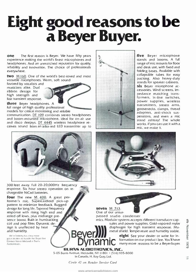
Eight good reasons to be a Beyer Buyer.
one The first reason is Beyer. We have fifty years experience making the world's finest microphones and headphones. And an unmatched reputation for quality. reliability and innovation. The choice of professionals everywhere.
two M160. One of the world's best -loved and most versatile microphones. Warm, soft sound favored by vocalists and musicians alike. Dual ribbon design for high strength and fast transient response. three Beyer headphones. A full range of high quality professional models for critical monitoring and reliable communication. DT 109 combines stereo and boom -mounted microphone, ideal for and disco deejays. DT 4445 wireless headphone re- ceives sound from an infra -red LED transmitter up to
headphones on -air use
five Beyer microphone stands and booms. A full range of mic mounts for floor and desk use, with fixed and folding bases. Available with collapsible tubes for easy packing. Also heavy -duty stands for speaker cabinets. six Beyer microphone ac- cessories. Wind screens, im- pedance matching trans- formers, in -line switches, power supplies, wireless transmitters, stereo arms, goosenecks, clamps, thread adapters, anti -shock sus- pensions, and even a mic stand ashtray! The whole works. If you can use it with a mic. we make it.
300 feet away. Full 20- 20.000Hz frequency response. Six hour stereo operation on re- chargeable NiCad batteries. four The new M 400. A great per- former's mic. Supercardioid pick -up pattern to minimize feedback. Rugged design for long life. Tapered frequency response with rising high end and rolled off lows, plus midrange pre- sence boost. Built -in humbucking coil and pop filter. Dynamic de- sign is unaffected by heat and humidity.
We're looking for a few more great dealers to handle the Beyer line. Contact Norm Wieland at Burns Audiotronics.
seven M 713. One of our unsur- passed studio condenser mics. Modular system; accepts different transducer cap-
sules and power supplies. Gold- vapored mylar diaphragm for high transient response. Mu- metal shield. Temperature and humidity stable.
eight See your dealer or write for in- formation on our product line. You'll have many more reasons to be a Beyer buyer.
Beyer)))) Dynamic
BURNS AUDIOTRONICS, INC. 5 -05 Burns Avenue, Hicksville, NY 11801 (516) 935 -8000
In Canada, H. Roy Gray, Ltd.
Circle 42 on Reader Service Card
www.americanradiohistory.com

N
magnefex Serving the Recording Industry for 20 years.
Model ATD -7 - $675.00 Delivered
Endless Belt Automatic Tape Degausser. The first endless belt degausser was The Magnefax ATD -7 will degauss 5" designed and marketed by Magnefax or 7" reels, audio cassettes and carts. in 1966. Continuing research has pro- Video cassettes may be degaussed in duced the current model which offers two passes with turnover. high flux, reduced heat build -up and The current requirement is only 4.5 one -fourth the power requirements of amps. at 120 volts. The size is 26" x competitive brands. 11" x 4 ". The unit weighs 65 lbs. The ATD -7, shown above, reduces The unit is conditionally warranted for noise level to that of virgin tape. Erasure three years and will provide years of is complete and over 1,000 tapes may dependable service. be degaussed in a twenty minute rún- ning period. RFD 1. ROGERS, ARK. 72756. 501/925 -1818
Circle 34 on Reader Service Card
SPECIFY EXCELLENCE! from the company who pioneered equalization
ACTIVE AND PASSIVE EQUALIZERS 18 different Models to choose from
REAL TIME ANALYZERS Octave Band. one -third and one -sixth octave
BI -AMP AND TRI -AMP CROSSOVERS Low -level at any frequency and slope
NARROW BANDWIDTH NOTCH FILTERS Control of room feedback and ring modes
CUSTOM FILTERS FOR AUDIO APPLICATIONS High -pass low -pass band -pass notch
SEND FOR OUR COMPLETE PRODUCT CATALOG
\Mac INSTRUMENTS, INCORPORATED P.O. BOX 698 AUSTIN, TX 78767 (512) 892 -0752
Circle 23 on Reader Service Card
common type pads, broadcast equipment catalogs often have already computed the resistor values for various losses and have these listed in chart form.
Whether you compute the resistor values or select them from a chart, there is one thing to keep in mind -the pad will not be a precision pad. You will use standard stock value resistors, and these seldom come out to the exact values that were calculated for the pad you need. Because of this, the pad will be somewhat less than precise, yet entirely satisfactory for many situations.
MOST COMMON PADS The two most common pads you will
use for these less than precision cases, are the "T" and the "H " pads. These pads get their names from the appearance of the schematic diagram which appears as a letter T, or an H on its side. These two are essentially the same pad, however, the "T" is for unbalanced circuits and the "H" for balanced circuits. Since either pad contains the same total resistance value, it is necessary to compute the values only for the "T" pad. That is the way the formula is designed. In the situation where an "H" pad is needed, simply divide the R I value into two equal parts and place one on each side of the
Figure 2. The "T" and the "H" pads. The 'H" is the same as the "T ", but arranged for balanced circuits.
RI R2
Z1 -1- R3
"T" Pad
RI R2 2 2
ZI
Formulas:
R3 Z2
RI 82_ 2 2
"H" Pad
R3= 2 N Z2
N-1
R,= Z,
R2= 22
(N + 1)
(N - 1)
(N + 1)
(N - 1)
Z,= Source Impedance Z2= Load Impedance N = Loss in dB
R3
R3
www.americanradiohistory.com

For the third time in America, we'll be demonstrating
a Mitsubishi Pulse Code Modulation audio recording system.
For the first time in America, it actually a production model.
MITSUBISHI ELECTRIC CORPORATION
Mcico Sales, Inc., 3010 Fast Victoria St., Compton, CA 90221. (2131537- 7132.AES Show, Booths 689 -691. Circle 32 on Reader Service Card
w
www.americanradiohistory.com

or r, rn
mikes by mail? for less? why not!TM
cued mud mace / The Mike ShopTM now sells audio equipment
as well as mikes by mail! for less! Write or call us with your requirements or for ourprice sheet.
The Mike Shop' PO Box 366A, Elmont, NY 11003 (516) 437-7925
A Division of Omnisound Ltd.
Circle 56 on Reader Service Card
A professional makes even the tough jobs seem easy That's the way it is with Waters professional audio attenuators. They feature glass -hard MystR' conductive plastic elements and slip rings as well as precious metal contacts. What's more, Waters computer -controlled curve -shaping technique assures superior tracking.
Result: smooth, quiet, long -life performance under the most grueling service conditions.
You'll find Waters complete line of professional audio controls meets every need - linear or rotary motion - mono, stereo, or quad. Two standard impedance values are now available, 600 or 10,000 ohms.
If you're into mixing, you ought to get the complete
story on Waters audio controls. Write today, or call us at 617 -358-2777.
It's the professional way.
WATERS MANUFACTURING, INC.
... ay.and MA 778 ò' 7 -358 -2777
.i^ Circle 16 on Reader Service Card
pad input to balance the circuit. Do the same with the R2 value on the output side of the pad. R3 (shunt value) re- mains the same in either case. Either of these pads can be used to provide a fixed - loss between two similar impedances, or as a fixed -loss -plus- impedance trans- formation between two dissimilar im- pedances.
When impedance transformation (matching) is all that is desired, then use the "L" or the "U "pad. These provide the impedance transformation with mini- mum loss. The lesser loss results from the fact that fewer resistors are used. Again, the "L" pad is for unbalanced circuits, and the "U" pad is for balanced circuits. Calculate for the "L" pad and then divide the series arm into two equal values for the "t'" pad.
OTHERS Besides the common pads discussed. a
variety of other configurations can be used for situations of bridging, matching, and other loss uses. Reference books will show many of these. as well as the necessary formulas. Once you have found one or two styles that work well for you. stick with them.
One such pad I came across many years ago and have used extensively is for
Figure 3. When matching -only is desired, use the "L" or the "U" pad. The "U" pad is for balanced circuits. There will be loss, but less than that of the "T "or the "H "pad.
Z,
,,-.11.
Formulas:
ñl
R3
L" Pad
ñ? Z?
RI
"U" Pad
R, = Z,
' Z,
Z R3-
N/1772- Z,
Z, = Source Impedance Z2= Load Impedance
www.americanradiohistory.com

ACOUSTICOMPUTER :. a true stereo special effects processor For further information call or write Phil Markham at DeltaLab Research, Inc.,
27 Industrial Avenue, Chelmsford, MA 01824, Tel. (617) 256 -9034.
Del taLab DeltaLab Research, Inc. 27 Industrial Ave., Chelmsford, MA 01824
Available at Quality Dealers
"See us at NY AES Show at Suites 5L & 5M" Circle 18 on Reader Service Card
www.americanradiohistory.com

situations requiring the division of a signal source into two equal loads, or the mixing of two equal sources into a common load. For example, the two outputs of a multi -tray cartridge tape player into the single console fader, or combining Left and Right stereo audio to form a mono signal. The pad can be worked either way -one into two, or two into one. The pad is made up of (3) 600 ohm resistors and is for 600 ohm circuits. There is a 6 dB loss across the pad.
BUILDING THE PAD Once the required loss, and impedance
configuration have been determined, and
60041 #1 OUTPUT
(6OOfi )
INPUT 6OOS1 60051
60011 #2 OUTPUT
(60o.n)
Figure 4. A simple pad for mixing or dividing the signal in 600 ohm circuits. This pad can be worked in either direction.
Controllability. Reliability. Variety.
Neptune knows that not everyone has the same equalizer needs. That's why Neptune builds 4 - dual and single channel models, a one -third octave unit, and now our new dual channel parametric model. What variety Neptune offers with the industry's four - most equalizers. Each is
lightweight, highly portable and totally rackable. Our catalog tells all. See your Neptune dealer or write for your copy.
Neptune Neptune EIecI10nes. Inc. 934 NE 250, A..w0 IswtpMryI50JJ 044!
Circle 45 on Reader Service Card
the resistor values computed. you are ready to build the pad. The first thing you will discover is that there may not be many stock value resistors that equal those computed values. Select resistors from the stock values which are the closest to the computed values. The closer you come in this regard. the closer the pad will produce the predicted results. Although the values will not be exact, they will generally be close enough so that the pad will produce generally- acceptable results. Should the stock values you have be far from the com- puted values, you can add series resistors to bring the individual values near the computed value. In any case. when building an "H" pad or other balanced pad, use an ohmmeter and actually measure the individual resistors that will be used on each side of the circuit. selecting those values that will maintain the circuit balance.
However you construct the pad. physically. may depend upon its physical location in the system, as well as your own ingenuity. The important thing is to identify which are the input terminals and which are the output so that it can be connected into the circuit properly. The second important thing is to insulate the internal connections of the resistors in the pad so that they do not accidentally short to a cable shield or the chassis.
MEASUREMENT W hen all is said and done. the
performance of the pad in the circuit will generally show if the effort was successful or not. Since, in most applications. a difference of a few dB is immaterial to what is intended, the pad should produce acceptable results.
But if ,you desire to know what actual loss the pad will produce before you install it in the circuit - measure it. Set up the audio signal generator and the audio voltmeter. Set the generator output impedance to the value that will be found in the actual circuit. and add a resistor load across the output of the pad which is the same as will be found in the circuit. Feed some arbitrary (but known) value of sine wave into the pad. and measure the level of that sine wave at the output of the pad. The difference between the input signal level and the measured output signal level is the loss the pad is producing.
RECAP Audio quality and operational con-
venience require signal level control throughout the system. The control is
achieved by on -board variable gain controls. some precision fixed -pàds. and many non -precision pads. By a little effort in calculation and work in assembling pads. the station engineer can construct inexpensive pads for non- critical areas that serve a very practical end in terms of audio control and operational convenience.
www.americanradiohistory.com

1966 1968 1970 1972 1974 1976 1978 1980
50,000 Tracks Of Dolby Noise Reduction In November 1979. the number of audio tracks throughout the world equipped with Dolby A -type noise reduction passed the 50.000 mark. No other single form of signal processing has ever been so widely accepted by professional sound engineers.
The reason is simple. Every practical method for storing and transmitting sound adds noise to the original signal. The Dolby system diminishes the noise by 10 dB without audible side effects on any kind of program material. This performance is maintained with any type and amount of noise encountered in normal professional applications. Add proven dependability and world -wide compatibility. and that is why each year more and more professionals continue to choose Dolby noise reduction.
The original Dolby noise reduction unit was the two -channel A301, nearly all of which are still in use. Today there is a range of models for every application, from the MH series for multi -track recording to the CP series for cinema sound reproduction. Together they account for the more than 50.000 equipped tracks now fulfilling the Dolby system's original promise: effective noise reduction combined with complete signal integrity.
DOLBY LABORATORIES, 731 Sansome Street. San Francisco CA 94111. Telephone (415) 392 0300. Telex 34409. 346 Clapham f tnad London SW9. Telephone 01 -720 1111. Telex 919109. Dolby and the double -D symbol are trademarks of Dolhy Lahorninnes
Dolbÿ Circle 50 on Reader Service Card
www.americanradiohistory.com

CO
NORMAN H CROWHURST
Theory St Practice
Systems Design In Audio
Recent affairs in my life have stressed the importance of the systems design concept in many contexts, not limited to engineering. And that, in turn got me thinking about how systems design -the same concepts -have influenced the growth of audio to its present stage of development.
When I was a boy in school, there were two audio systems: radio (a.m.) and phono (laterally -cut mono). But then engineers didn't even think about radio
being a.m., because f.m. had not been introduced: and while the earlier phono- graphs had used vertical cut, lateral cut was generally conceded to be an improve- ment -much less distortion - so vertical cut was no longer thought of as a viable alternative.
But we did have equalization, and later there was vari -pitch recording, to get more onto a record, and then there were record changers, as an alternative to manual turntables. Perhaps the intro-
duction of standardized equalization was the first step toward systems. Before that, recordings. or radio broadcasts did not pay much attention to frequency response.
CONSTANT AMPLITUDE & CONSTANT VELOCITY
Awareness of constant amplitude, or constant velocity, as applied to record- ing, and its equivalent in radio, led to finding an equalization characteristic, or curve, that would be a successful
Two More Springs For No More Money
Now Orban advances its price /performance leadership in compact, professional reverb systems. Our 111B Dual Reverb now comes with six springs per channel at no increase in cost.
You get: Lower flutter Higher echo density Smoother, more natural sound
Plus, these Orban standard features: Advanced signal processing Floating threshold to minimize twang Midrange parametric equalizer Bass shelving equalizer
For the 111B Reverb and other fine professional audio products, see your local dealer, or contact Orban for the location of the dealer nearest you.
Hear it at AES Booth 28
or ban Orban Associates Inc. 645 Bryant Street San Francisco, CA 94107 (415) 957 -1067
Circle 37 on Reader Service Card
www.americanradiohistory.com

We're still at it. We started in 1935 as the Audio Development Company producing jacks and jack panels for the broadcast and telephone industries. Since then, ADC has produced such innovations as Bantam Jacks, printed circuit board jacks and Wrapid terminal blocks. What are we doing for you today? ,pr
ADC Products
We are introducing our new line of low impedance audio
connectors. We have six models now in production. They're reliable, compatible
and competitively priced. Most important, they're available soon-
er. Ask about making a sound con- nection with ADC. Call or write today.
A DIVISION OF MAGNLTIC CONTROLS ADC Products. 4900 W 78th St . Minneapolis. MN 55435 / Telephones. (612) 835 -6800 TWX 910.576 -2832 Telex 29 -0321
Sales offices in' Atlanta. GA (404) 766 -9595 Deltas. TX (214. 241 -6783 Denver. CO (303) 761 -4061 Fairfield. CT (203) 255 -0644 Lafayette. IN (3171474-0814 Melbourne. FL 1305) 724 -8874 Menlo Park. CA 1415) 323 -1386 Minneapolis. MN (612) 835.6800
Washington. DC ( 202) 452 -1043 Montreal. Quebec (514) 677 -2869
Circle 41 on Reader Service Card www.americanradiohistory.com

0
compromise between the two. Constant amplitude means that the same sound pressure will produce the same amplitude of stylus movement, as frequency is
changed. Constant velocity means that the same velocity of stylus movement will correspond with the same sound pressure at different frequencies.
These terms of reference did not come into existence before electrical tran- scription was invented. They would have little meaning, applied to the old acoustical phonograph. They might have a corresponding meaning applied to radio. but the relationship would be to diaphragm movement at the microphone or loudspeaker (then they used head- phones rather than loudspeakers), so the whole concept of such a relationship was quite new.
TRANSDUCER TYPES However, there are correspondences
with transducer types. A dynamic type transducer, which uses an electro- magnetic element such as a moving coil. produces a response which is inherently constant velocity, because the voltage generated by the pickup or microphone, or required to drive the cutter -head or loudspeaker, is proportional to the velocity of movement, whatever the frequency.
Static transducers, such as piezo- electric, or capacitor (then called "condenser ") produce an inherently constant amplitude relationship: voltage is proportional to amplitude of move- ment, regardless of frequency. These prove to be oversimplifications in the real world, but they are the basic relation- ships on which each kind of transducer works.
Velocity and amplitude are related by frequency. Given constant amplitude, velocity is proportional to frequency: because moving over the same amplitude at a higher frequency increases the velocity needed to maintain that ampli- tude. And given constant velocity. amplitude must be inversely propor- tional to frequency, because the longer periods corresponding with lower fre- quencies require greater movement to maintain the same velocity.
From that relationship. expressed in its basic terms, it would seem that static transducers are the best choice. Use of dynamic transducers, with the naturally related constant velocity, requires quite large amplitudes for the lower frequen- cies. But that is a theoretical choice that does not actually "follow through" as well as might be expected. Control forces and electrical circuit values inevitably make devices that are basically of the
"static" type, perform like constant velocity, below some critical frequency, generally known as "cut- off."
SYSTEM DESIGN So. we begin to introduce the various
parameters that make it necessary for us to think in terms of system design. How much program can we squeeze into a given recording space, measured in those days on disc? When magnetic recording came along later, the same question arose, in only a slightly different context. And on radio, how much information can be squeezed into a given radio band. or spectrum. by using different channels. or station -frequencies?
Earlier columns in this series have addressed dynamic range- and noise - versus- distortion. These are the factors that decided on the best choice of equalization characteristic: how could you modify response during recording and playback, so the best dynamic range could be squeezed into the minimum space? A systems design question. the first of many to follow it. in greater profusion.
The space question is tied to the level of recording, as well as to its frequency content. Lower frequencies require greater amplitudes, if one spiral of the groove is not to break through into the
You do the talking ... The Syntovox Vocoder does the rest Introducing the intelligible and affordable Syntovox 221 Vocod- er from Holland -a 20- channel analyzer /synthesizer which allows the creation of many ex- citing, new voice effects as well as speech analysis and syn- thesis. With the Syntovox, a voice input can be imprinted on any musical instrument or sound effect to create truly unbelievable "talking musical effects." Technical features of the 221 include the use of 8 -pole filters with initial roll -off of 54 dB /octave, assuring high intelligibility, matrix patching of analyzer and synthesizer sections, and a built -in audio pulse generator for simple
am
and effective speech synthesis.
Musicians will love the Syn- tovox 222, a simplified, yet versatile adaptation of the larger studio vocoder. The 222 allows the performing musician direct vocal control over each note which is played. And any voice can be transformed to cover a range of many octaves when interfaced with a syn- thesizer keyboard. Choral sounds, percussion effects... the "triple -two" does it all and much more!
Hear for yourself the new wave in vocal processing -the incredible, intelligible Syntovox Vocoders.
s synt HOLLAND
registered trade mark of synton electronics by
Exclusive Sales & Marketing:
Parcbound 680 Beach St., Suite 414
(415) 673-4544 San Francisco, California 94109
Dealer Inquiries Invited
Circle 24 on Reader Service Card
www.americanradiohistory.com

The logic behind the Revox B77.
The logic is the logic which is built -in.
It's an ingenious and highly sophisticated systemm much like the human nervous system -which controls the deck's functions.
You can push any button in any order with no chance of damaging your tapes. Our motion sensing system con- stantly feeds status reports to the logic circuitry which activates your commands in proper sequence.
The logic also permits full -function remote con- trol, and an editing mode that keeps the playback cir- cuitry live, even when the motors are stopped. You can make your splices right on -the -beat, and our built -in splicing block makes it easy The design and construction of the Revox B77 further guarantee smooth and accurate operation. lb get the
long -life advantage of' ferrite without static build -up or heat degradation, we use Revox's exclusive Revodur heads, made of metal to dispel heat and static, and vacuum -coated with permalloy for durability.
The B77 has a unique capstan motor that's monitored by a tacho head to precisely control speed and limit wow and flutter to professional studio standards.
Revox offers many options with the B77 including a full range of speed configurations from 15/16 IPS to 15 IPS, variable speed control, 1/4 track record /playback and more.
All this professional quality is neatly engineered to fit in a deck you can carry. After all, if you own a machine this good, it's logical to take it with you.
Experience the B77 and the full line of Revox and Studer professional products at your franchised dealer today.
..-...a
J .1.1.1.E I, À
WOWS --
ADD CEG's REVOX America, Inc. 1819 Broadway, Nashville, TN 37203 615 329 -9576/ In Canada: Studer Revox Canada, Ltd.
Circle 31 on Reader Service Card www.americanradiohistory.com

N
next, and high' levels also require greater amplitudes of stylus movement. But program varies in dynamic level. so that in quiet passages a lot of grooves can be squeezed in. while on loud passages each groove must be given more space.
VARI -PITCH Thus the idea of vari -pitch was born.
At First, this was achieved manually, by the record cutter changing the pitch, a
little ahead of loud passages. to give more room, and closing them up again on quiet passages, to get more grooves onto the record. This depended on the skill of the operator who cut the records, and on his having an adequate score for cueing him when the loud and quiet passages were coming.
Systems design gets this kind of thing automated. How can it do that? Use of tape for mastering facilitates this. By running the tape past a "monitoring" head, before it gets to the playback head used to provide input for recording. the machine can "know" when the louder and quieter passages are coming, with a
fixed "advance notification" set by the spacing between the heads, and the speed at which the tape passes them.
Now we come to how technological improvement influences system design.
In the early days of phonograph design, a
pickup required a force measured in ounces, to keep the stylus (then more often called a "needle ") in the groove. Improvement in pickup design has brought this force down. until it is measured in grams. or even in fractions of a gram. This has been brought about. not only by changes in pickup design. but also by changes in record material.
The old records used a 3 -mil stylus, or needle. Nowadays the maximum is I -mil. The old needles wore down quickly. due to the abrasive in the record. part of whose purpose was to prevent the needle going out of shape -which it did. anyway. more quickly than its user liked: to get good performance. the needle should be changed after each record played (and that was less than 5 minutes' duration in those days). The advent. first of sapphire styli, and then diamond, changed this, as well as making the smaller radii practical.
This opened the way for longer playing discs, the EP and LP, each of which adopted its own systems design ap- proach. RCA's Extended Play (EP) introduced the large hole in the center. adapted to a new system of record changing, suited either for juke boxes, or for the teenage record -player market. CBS' Long Playing (LP) used the same
sized discs as before, but changed groove size and speed. Groove size dropped from 3 mil to I mil, and speed dropped from 78
rpm to 33 rpm. RCA's EP chose 45 rpm. also with a finer groove size, and a
smaller disc. for greater convenience.
SYSTEM DESIGN APPLIED TO RADIO
All of these choices involved systems design concepts. to optimize what its designer wanted the system to do. Meanwhile - in fact long before that - radio was having its problems. While the disc recording was bothered with how much program could be squeezed into each disc. radio was bothered with how many channels could be squeezed into the "air space " - -or radio spectrum.
This is what led to the adoption of f.m. for the higher radio frequencies: to use up more of the spectrum. to get audio modulation of higher dynamic range. rather than over- modulating on the very limited side -band range provided by a.m. Here again. systems design concepts led to choice of equalization. channel spacing and so forth.
WHAT ABOUT STEREO? Now into this scene with already -
proliferating systems, enter stereo. Up till
COMPRESSOR LIMITER WAWA
7 - Lows wrt
IOW RUM TIMOL11
M OUT ON Oil n 75 8 770Rt 7 i! trip *is tot is
flS1151 PFUI{POT NliArtiOl 015O1R COMO
r-COIIMEs'° 1 7
The Orange County CLX -S -FM belongs in your studio to assure you of transparent, accurate stereo or dual - channel processing with maximum control. It is a
powerful new tool for the creative producer /engineer. Compresso: with adjustable ratio, threshold, attack and release times, for loudness enhancement Fast peak limiter with 250:1 slope for overload protection Highly effective expander /noise -gate for noise reduction High frequency limiter with selectable pre -emphasis characteristics Extremely accurate stereo tracking Overall performance specs and construction to the highest industry standard Also investigate the VS -3 Stereo Processor which
offers internally pre -set functions for the budget - conscious user looking for great sound.
ORANGE COUNTY ELECTRONICS INTERNATIONAL INC.
Exclusive Sales & Marketing:
Dealer Inquiries Invited 680 Beach Street, San Francisco, Ca. 94109 (415) 673 -4544
Circle 15 on Reader Service Card www.americanradiohistory.com

Two pairs of Bose" Model 802 loud- speakers and a Bose Model 1800 Power Amplifier. We call it the Super - Bose System. Stacking two pairs of 802s doubles your sound output and quadruples your bass (with the help of acoustical coupling). Stacking also doubles the projection and sensitivity of the 802s. The Bose Model 1800 Power Amplifier is a reliable. rugged. dual -channel amplifier just right for the power capa- bility of two pairs of 802s. The Super -Bose System is half the weight and a quarter the size of con- ventional systems. Less trouble to pack and carry. less room taken up in your car or van, less hassle unpacking and setting up.
The Super -Bose System adds up to a
big. natural sound that stands alone for realism and clarity. Dont take our word for it. Check it out at your author- ized Bose Professional Dealer today
Bose Corporation. Dept. SE
The Mountain Framingham. MA 01701
Please send me a copy of the Bose Professional Products Catalog and a complete dealer list.
Name
Street
City.
State
Tel(_
L--
Zip
Two times the sound. Four times the bass. Half the hassle.
SSUCd and Lendini;
www.americanradiohistory.com

MARTIN DICKSTEIN
Sound With I
A Bit More On The Visual Communications Congress
You will recall that last month we discussed the meetings that took place at the Visual Communications Congress, held at the beginning of the summer. It was mentioned, in that column, that we would try to cover the exhibits that were shown during the Congress. Well, that time is here. We'll do it alphabetically; simply because we do not want to show any preference, nor do we mean to imply a "plug" for any of the equipment or services. The various exhibits are being
mentioned and described, here, to indicate the scope of the overall coverage and to provide information about some of the items, of which you may not be aware. By the same token, we will not mention all of the exhibitors, as there were about 300 of them -and just listing them would run a full length column and more.
Among the "A's," there was American Innovative Marketing of Santa Ana, CA, showing how a "Digi -tiser program-
mable message center" worked; Ameri- can Movie Network (NYC) explained their computerized closed- circuit pay tv system; Ampex; and Anvil Cases, manufacturer of custom made trans- portation and storage cases for video, audio -visual, camera equipment and delicate instruments.
Bergen Expo Systems (Clifton, NJ) was there displaying their Xenon slide and 16mm projectors, Quadapoint Light Valve, Eterna 16mm endless loop
(Continued on page 30)
Another original design from audio & design recording Create your SCAMP system from these interchangeable modules:
Compressor- Limiter Microphone Preamp (transformer -less) Sweep Equalizer Parametric Equalizer Dynamic Noise Filter /Gate (high -pass) Dynamic Noise Filter /Gate (low -pass) Octave Equalizer Distribution Amplifier L.E.D. Quad Display Column Pan Effects Module (automatic panner) Time Shape Module (ADT /Flanger) Expander Gate Dual Gate
Equally at home on the road or in the studio! SCAMP may be purchased piece by piece as budget allows.
aiaudio & design recording
Providing the international audio industry with clean, quiet. dependable Signal Processing for more than 15 years. Excellent specs. Exemplary sound. Definitive practicality.
Nigel Branwell. ADR. P.O. Box 786. Bremerton. WA 98310 (206) 275 -5009 TELEX 15 -2426.
www.americanradiohistory.com

The CS15P condense ardioid microphone is equally at home in a re- cording environment or broadcast studio. When hand -held it puts sex appeal in
a voice with its bass -boosting proximity effect. With shaped high- frequency response and its ability to handle high sound pressure levels (140 dB with 1% THD at 1kHz), the CS15P is ideal for close -up vocal or solo instrument miking applications.
When boom mounted, the CS15P has better gain- before -feedback and a better signal -to -noise ratio than most shotguns. It's phantom powered and it's rugged.
The CO15P condenser omni extends frequency response to the very limits of audibility, 20 to 20,000 Hz. Un- like other "omni's;' the CO15P maintains its omnidirectional polar pattern at the very highest frequencies. Perfect for the distant miking of an entire orchestra as well as up close on individual instruments. And like the CS15P, it's phantom powered and it's rugged.
The Electro -Voice warranty Electro -Voice backs up these two mi- crophones with the only unconditional warranty in the business: for two years we will replace or repair your CS15P or CO15P microphone, when returned to Electro -Voice for service, at no charge - no matter what caused the damage!
Circle 40 on Reader Service Card
We can do this because we build these microphones to meet our standards for performance, ruggedness and durability. We accept nothing less, and if you're a professional, buying a professional quality microphone, you shouldn't either.
G U LI System C
7
Electrol/oicé a gultan company
600 Cecil Street. Buchanan. Michigan 49107
www.americanradiohistory.com

SWEAR OUR
THCOMPETI1ORS I.S N DIGITAL ÉLS FS LLTHREYEARÓ'
ss 111111 111111 111111 sss sss sss.ss...assass... ass ass saaaaaasa.a..aaa.a.a. ss 111111 111111 1111 ss11 sss sss a 11aa s.s sss s..sas..saaa...saaa.aasaa..aaa 111111 111111 1111s 11ss s1111 111111 sss .1111 ass ass sas a...s...a.a,sasaaa ass aaaasa.ta
11 11 s s 11 11 sas s. s ass %%X s a s , s. %% as a \N a ... N.`1.16 asa ..a ass aas O 11 s s s.. ',N.% .. sas ',CV,. a a a s a. ass ',Ns s. s ass
e 1979 Sony industries, a Dn, of Sony Corp of America, 9 Wiest S7th St , NY, NY 1009 Sony s a registered trademark of Sony Corporation
www.americanradiohistory.com

Almost everybody admits digital recording will someday be the ideal way to make records.
With a Sony PCM -1600 system, you can stop waiting for that someday to happen.
And start recording now. IN THEORY, ALL DIGITAL SOUNDS TERRIFIC.
IN REALITY, SONYACTUALLY DOES. If your ears are even in semi -reliable condi-
tion, you've no doubt been exposed to incredible amounts of digital audio hype.
"The most dramatic change in audio since flat records," says one prestigious audio publication. "At last...perfect sound reproduction," notes another.
So instead of dwelling on how digital can improve the sound of your recordings, we'd rather dwell on how Sony -and only Sony -has finally made digital performance live up to its promise.
"WE'D LIKE TO DEDICATE THE NEXT FEW NUMBERS TO THE SONY
ENGINEERING DEPARTMENT." In order to convert regular audio signals into
digital, the Sony PCM -1600 digital recorder uses a pulse code modulation system developed and perfected by Sony engineers.
The same people who have been behind vir- tually every audio and video breakthrough since the late 1940's.
Consequently, the dynamic range of the two track PCM -1600 is greater than 90dB.
Frequency response is 20 to 20kHz.
The total harmonic distortion of the PCM -1600 is inaudible over the entire audio spectrum.
There is no measurable wow and flutter. And because the PCM -1600 puts binary
code on tape instead of audio signals, it's not susceptible to tape hiss or print- through; there's no need to subject your music to noise reduction equipment or realign your recorder for bias and equalization.
EDITING PROBLEMS HAVE BEEN FADED OUT. Since the PCM -1600 works in conjunction
with two Sony video recorders, a standard Sony video editor, the BVE -500A or the new DEC -1000 will fill your every editing need.
DROP -OUTS HAVE BEEN DROPPED. Based on a technique used by computers
(where the loss of a single bit of information could mean millions), Sony engineers have created an ultra- sophisticated digital correcting code that can actually restore "dropped out" information.
And considering that Sony video recorders are virtually immune to this problem in the first place, the chances of it plaguing your sessions are all but negligible.
DIRECT -TO -DISC QUALITY WITHOUT DIRECT-TO-DISC LIMITATIONS. Because digital quality doesn't deteriorate
from one tape generation to another, the PCM -1600 lets you make generation after generation of lac- quers, all with direct -to -disc quality-but without any limitation on the number of lacquers you can press.
And if you use the digital format for distribu- tion to your foreign affiliates, you're guaranteed that your last digital master will be absolutely identical to your first.
SONY INTRODUCES TWO NEW WORDS TO THE DIGITALVOCABULARY:
AVAILABLE NOW Unlike other digital equipment, the PCM -1600
is actually available for delivery today. Not six months from now. Or "when we finally get all the
bugs out" PCM- 1600's are cur-
rently being used by well - known recording stars, and are already in opera- tion at Polygram, CBS, Spectrum Sound and Digi- tal Recording Services in Los Angeles, and Digital Recording Systems in Philadelphia.
A FEW SONY DIGITAL ADVANTAGES
YOU CAN'T HEAR. Besides the quality
and reliability Sony equip- ment is legendary for, we've set up a 24 -hour
digital hot line to service our customers. We're prepared to provide as much technical
expertise and engineering assistance as only Sony possibly can.
And we intend to continue our exhaustive research in digital audio -and share future insights with the growing Sony digital family.
If you'd like more information about any facet of Sony digital equipment, contact Roger Pryor at (415) 467 -4900.
You may think you've heard a lot about digital in the past.
But until you've heard Sony, you haven't heard anything yet.
SONY DIGITAL AUDIO We've never put our name on anything
that wasn't the best.
Circle 25 on Reader Service Card
www.americanradiohistory.com

0 th
sound with images (cont.)
attachment, and to introduce the Mini - X2 16mm film projector with Xenon lamp -house attached. Blackbourn. Inc. of St. Paul. MN, showed video storage albums for l/ -inch and 4 -inch tapes. albums for 5 -inch and 7 -inch video reels. and their multi -media packaging: while Buhl had slide and film lenses, film and video multiplexers. and a high resolution slide projector.
Among the "C's." there was Cargo Case Division. ICOM. Inc. of Columbus. OH. manufacturers of heavy -duty pro- tective shipping cases. Clear Light (Ft Lauderdale. FL) showed its multi -image
control devices; Command Productions (White Plains. NY) displayed samples of their slides and filmstrips, and discussed their graphic and audio -visual produc- tion services; Creative Communications Group of Dallas, TX. also had a multi - image and live stage production to offer; and Crestron Electronics (Closter, NJ) had four models in their Executive Series of wireless audio -visual systems to show
Devlin Productions (NY) had a booth to discuss their new Mark 3 Flying Spot with Digiscan for film -to -tape transfer. their world -wide television standards conversion equipment and services, their CMX 340X hi -band computerized editing system.
(What happens next is the differ- ence between Fidelipac Blank -IT and your current bulk eraser)
Break the law of gravity with your current bulk eraser and go pick up an- other one. Do the same with Blank -IT. and just go pick it up. Blank -IT goes right on bulking.
Fidelipac houses Blank -IT in a light- weight, balanced case that's virtually indestructible. Installs a high mu core with a longer ON duty cycle and more magnetic strength than any hand -held
FLECTHONICB by HOELIPAC®
eraser. Builds thermocouple protection into that core for burn-out proof opera- tion. Tops it with a balanced, contoured handle that stays where we put it. And unconditionally guarantees Blank -IT against electrical burnout and mechan- ical breakage for a full year after purchase.
$5995 Manufacturer's Suggested Retail Price
Blank -IT. By Fidelipac. The first hand -held bulk eraser guaranteed to stand up. After the fall.
109 Gaither Drive Mt. Laurel. NJ 08057 U.S.A. (609) 235 -3511
Circle 14 on Reader Service Card
R. Trademark
Fiberbilt Photo Products, a division of Ikelheimer -Ernst (NY) showed their AV carrying cases, tv shipping cases, and monitor shipping cases; Freen Screen (Rockville. MD) discussed their rear screens: GE displayed its large- screen color video projector; Genigraphics showed the results of its slide and VU- graph process by computer; and Hitachi demonstrated its portable and studio camera systems.
Image Transform (NYC) talked about their videotape -to -film transforms in 16mm and super 8mm. and their film - to -tape transfer with the exclusive ITM telecine; Image West (Hollywood. CA) showed electronic animation: and "The Incredible Slidemakers." (NY) showed special effects slides and how they can help with multi -image presentations.
Kimchuk (Brookfield, CT) demon- strated their method for stacking slide projectors, StereoStand (for 2 projec- tors), 3 -Hi for 3 projectors, and 4 -Hi for guess- how- many -projectors, and their animator unit which comes with modules that can be added together for different functions.
Elsewhere. in the "L's," Lewis Lek - tronics (Santa Clara. CA) showed its portable programmable electronic mov- ing- message sign. with a detachable keyboard programmer; while Loose Leaf Industries (South Plainfield, NJ) was exhibiting custom AV packaging for cassettes, filmstrips. records and slides.
Continuing with our survey of the Visual Communications Congress. ran- dom slide projectors and controls were displayed by Mast. Mediatech, from England, discussed their international equipment rental service; and Motion Message of Bohemia, NY showed their fully programmable electronic read -out sign. Lowell Nerge Filmstrips (Min- neapolis, MN) explained their "direct process for making film strips from 35m slides :" Optical Radiation (Azusa, CA) showed a programmable high -intensity Xenon slide projector; Optisonics HEC (Tucson, AZ) showed slide, tape syn- chronizers. dissolve units. variable dissolve synchronizers. remote projector controls. and portable slide show carrying cases; and Pak/ Master(Prince- ton, NJ) had custom AV packaging and complete warehousing and shipping services to offer.
Reliance Plastics and Packaging (Forest Hills, NY) demonstrated custom packaging for audio- visual materials; The Silver Image (Washington, DC) discussed AV software; Spindler& Sauppe (Hollywood. CA) displayed multi -image presentation systems; and Theater Techniques (Newburgh, NY) showed backdrops for tv, films. etc.
There were many, many more, too many to mention all, but this just goes to show that you should not miss the next Visual Communications Congress if you're in the field of AV.
www.americanradiohistory.com

We are pleased to announce that
TURNER has joined the growing product family of
TELEX HEADPHONES HEADSETS MICRO
PHONES TAPE COMPONENTS CASS
ETTE RECORDERS TAPE DUPLICATING
SYSTEMS LANGUAGE LABORATORIES
BACKGROUND MUSIC SYSTEMS IN-
FLIGHT ENTERTAINMENT SYSTEMS
TELEX' MAGNECORD TAPE RECORDERS /REPRODUCERS
LOGGERS
- an. electronics DIVISION OF TELEX COMMUNICATIONS. INC
'ANTENNAS TOWERS
TURNER DIVISION OF TELEX COMMUNICATIONS, INC
MICROPHONES ANTENNAS
AND A HOST OF OEM PRODUCTS PRODUCTS OF SOUND RESEARCH
TELEX COMMUNICATIONS, INC.
9600 ALDRICH AVE. SO., MINNEAPOLIS, MN 55420 U.S.A., Telephone: 612 -884 -4051, telex: 29 -7053 EUROPE: 22, rue de la Legion- d'Honneur, 93200 St. Denis. France, Téléphone: 820- 98 -46. telex: 63 -0013
Circle 20 on Reader Service Card
www.americanradiohistory.com
DRUM
PLATFORM
From New York to Nigeria. Sugarloaf's View is that we are on the frontier of a new era in recording studio design. In control rooms. time corrected monitor systems. new testing methods and new building materials are bringing us ever closer to truth -in- sound while studios themselves display our
N co
new thinking on isolation booths, drum en- closures. and live - dead flexibility. And we still work personally with every client. in order to bring ideas from drawings to reality. Sugarloaf's View is that unparal- leled design plus personal service is the formula for successful studios for the 80's.
SEciaRkoar iE ARCifÍTECTURAI & ACOUSTÍCAI DESÍgN
New Products & Servkes
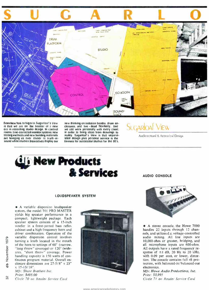
LOUDSPEAKER SYSTEM
A variable dispersion loudspeaker system, the model 701 PRO MASTER yields big speaker performance in a compact, lightweight package. Each speaker system consists of a 15 -inch woofer in a front -ported bass reflex cabinet and a high frequency horn and driver combination. Operation of the variable dispersion control involves turning a knob located in the mouth of the horn to settings of 60° (narrow. "long throw" coverage) or 120° (wide - area. "short throw" coverage. Power handling capacity is 150 watts of con- tinuous program material. Overall en- closure dimensions are 27 -5/8" x 23" x 15- 13/16 ". Mir: Shure Brothers Inc. Price: $495.00 Circle 70 on Reader Service Card
AUDIO CONSOLE
A stereo console, the Howe 7000 handles 22 inputs through 12 chan- nels, and utilizes d.c. voltage -controlled audio mixing. All line inputs are 10,000 -ohm or greater, bridging, and all microphone inputs are 600 -ohm. All outputs have a rated frequency re- sponse of ±-1 dB, 20 Hz to 20 kHz, with 0.09 per cent, or lower, distor- tion. The console contains full it pro- tection, with balanced -in /balanced -out electronics. Mir: Howe Audio Productions, Inc. Price: $3,995 Circle 71 on Reader Service Card
www.americanradiohistory.com

F W
BEFORE YOU KNOW IT
SUGARLOAF IS DOING It Circle 47 on Reader Service Card
SU(jARIOAI VIEW, INC.
31 UNION SQUARE WEST
NEW YORk, NEW YORk 10003 (212)675.1166
IOS1 p11 S1 Ili( k 1011N M. S1oRyk
ELECTRONIC MICROPHONE SNAKE
A system for transmitting low level signals from a stage to mixing or re- cording equipment, the MAINLIN- ER utilizes time- domain multiplexing. Each input is encoded and transmitted over a length of standard microphone cable to the decoder, where the signals are reassembled at their respective out- puts. Lo -Z mic inputs are standard on all models, however Hi -Z inputs are available as well. Cable runs of 700 feet are practical prior to any signal loss. Mir: IHD Audio Circle 72 on Reader Service Card
TRANSMITTER EQUALIZER
Substantially improving the average modulation and loudness capabilities of many transmitters using older modula- tion techniques, a new transmitter equal- izer accessory is now available for use in the OPTIMOD -AM Compressor Lim- iter/ Equalizer system. Designed to com- pensate for low frequency tilt inherent in many transmitters, and also to compen- sate for transmitter- antenna system over- shoot and ringing, the equalizer contains two separate sections (remotely switch - able) permitting independent adjust- ments of day/ night transmitters or day/ night power levels. Each equalizer sec- tion has three controls: one for low -fre- quency tilt, and two for high- frequency compensation. When desired, the entire transmitter equalizer can be switched out. A front panel jack permits insertion of square wave test signals for initial set- up. Day/ night status of the unit is indi- cated via led's. This new transmitter equalizer is available as an accessory kit for easy retrofit into existing units, and is oeing included on all current produc- tion units of the OPTI MOD-AM Com- pressor/ Limiter/ Equalizer system. Mfr: Orban Associates. Inc. ^ircle 73 on Reader Service Card
www.americanradiohistory.com

D 5dration 15a9 Industrial Road, San Carlos, California 94070 415/592 -8311 TWX: 910- 376 -4890 MANUFACTURED BY OTARI ELECTRIC CO.. TOKYO. JAPAN
The Best Professional Recorder Dealers in the United States ALABAMA
Sonics Associates Birmingham
ALASKA
Alaska Sound Anchorage
JTC Sound and Light Co. Anchorage
ARIZONA
E.A.R. Sound Consultants Tempe
ARKANSAS
Stanley Communications Little Rock
CALIFORNIA
A -1 Audio Rentals Hollywood
Accurate Sound Redwood City
Audio Concepts Hollywood
BCD (Brdcast. Comm. Devices) Anaheim
BCD
Santa Clara
Castle Music Goleta
Century Music San Jose
Mole Systems Orange
Coast Recording Supply Hollywood
Express Sound Costa Mesa
Media Generalists San Francisco
Pacific Recorders San Diego
P.A.S.E. (Pro. Audio Systems Engineering) No. Hollywood
RPS /Sound Foyer Los Angeles
Sound Genesis San Francisco
Suntronics Upland
Tritronics Burbank
Westlake Audio Los Angeles
COLORADO
Audiotools Boulder
Audio Visual Systems Denver
Boulder Sound Gallery Boulder
Colorado Springs Music Colorado Springs
Listen Up Denver
United Tapes of America Grand Junction
CONNECTICUT
Audiotechniques Stamford
LaSalle Music West Hartford
DISTRICT OF COLUMBIA
U.S. Recording Co.
Washington D.C.
FLORIDA
Continental Electronics Hialeah
Discount Music Orlando
Harris Audio Systems North Miami
Pro Audio General Store Coral Springs
Syscom Fort Lauderdale
Thoroughbred Music Tampa
GEORGIA
Electronic Equip. Co.
Atlanta
HAWAII
PSC Productions Honolulu
ILLINOIS
Audio Consultants Evanston
Audio -Trak Recording Rockford
Bridgewater Custom Sound Harvey
Broadcast Electronics Quincy
BSC Productions River Grove
Gill Custom House Palos Hills
Milam Audio Pekin
Roy Baumann Music Arlington Heights
INDIANA Allied Broadcast Richmond
Sound Around Indianapolis
IOWA
Advanced Audio Engineering Iowa City
KANSAS
Nichols Electronics Wichita
KENTUCKY
Custom Electronics Lexington
Electronic Labs Louisville
Sonic Services Louisville
LOUISIANA
Audiomedia Associates New Orleans
MARYLAND
Automated Broadcast Rockville
CMG Sound Rockville
Midwest Telecom Lanham
Recording Consultants Silver Spring
Veneman Music Rockville
MASSACHUSETTS
Lake Systems Newton
Lebow Labs Allston
Ring Associates Easthampton
MICHIGAN
Al Nalli Music Ann Arbor
Arnolt Williams Music Canton
Audio Distributors Grand Rapids
Fiddlers Music Detroit
Hy James Enterprises Ann Arbor
MINNESOTA
AVC Systems Minneapolis
MISSISSIPPI
Ideal Acoustics Starkville
MISSOURI
Larry Nicholson Productions Kansas City
Mirar Pro Audio Independence
North County Sound St. Louis
Mr. Music's Rock Shop Springfield
NEBRASKA
Mc Martin Industries Omaha
Mid -City Music Omaha
NEW JERSEY
Audiolab New Brunswick
Professional Audio Video Paterson
Turner Engineering Mountain Lakes
NEW YORK
Audio by Zimet Roslyn
Boynton Studios Morris
Cathedral Sound Rensselaer
Electronic Workshop New York
Harvey Sound New York
Martin Audio New York
Masque Sound New York
Merika Audio New York
Multi -Sonus Rochester
Northeast Broadcast Lab South Glen Falls
Pro Sound Labs Hempstead
Unistage, Inc. Buffalo
VSM Leasing Corp. Clarence
NORTH CAROLINA
Audio Unlimited Greensboro
Recording Services of WNC
Canton
Reflection Audio Charlotte
OHIO
Gattuso's Music Canton
Heyday Sound Toledo
Klopi Audio Dayton
Midwest Telecom Cincinnati
PI Corporation Cleveland
Swallens Cincinnati
Winteradio Parma
OKLAHOMA
Ford Audio & Acoustics Oklahoma City
OREGON
HIS Sound Gresham
Showcase Music Portland
PENNSYLVANIA
Audio Innovators Pittsburgh
Barclay Recording Winnewood
Blue Diamond Company Cannonsburg
Broadcom Allentown
Dimensions Five Womelsdorf
Holt Technical Services Bethlehem
George Heid Productions Pittsburgh
L.P.B., Inc. Frazer
Lerro Electrical Philadelphia
TENNESSEE
A.D. Studio Memphis
Broadcast Equip & Supply Bristol
Creative Audio Nashville
TV & Audio Engineering Brentwood
Valley Audio Nashville
TEXAS
Abadon Sun Inc. /ASI San Antonio
American Record Corp. Houston
Houston Cinema & Sound Houston
Hardin Electronics Ft. Worth
Ludwig Sound Houston
Midwest Telecom Dallas
Pran, Inc. New Braunfels
Sound Productions Dallas
Toby Arnold and Associates Dallas
Westbrook Audio Dallas
VIRGINIA
Alpha Audio Richmond
David Green Broadcast Consultants Leesburg
Electronic Engineering Norfolk
Midwest Telecom Virginia Beach
WASHINGTON
Broadcast Supply West Tacoma
Capitol Communications Olympia
Hoffman's Music Spokane
Pro Audio Seattle Seattle
Puget Sound Tacoma
RMS Sound Seattle
WISCONSIN
Flanner and Hafsoos Milwaukee
Full Compass Systems Madison
Video Images W. Allis
Dealers for the Otani MX -7800 1 -Inch 8 -Track ALABAMA
Sonics Associates Birmingham
ARIZONA
E.A.R. Sound Consultants Tempe
CALIFORNIA
Accurate Sound Redwood City
ACI /Audio Concepts Hollywood
Express Sound Costa Mesa
Sound Genesis San Francisco
Westlake Audio Los Angeles
CONNECTICUT
Audiotechniques Stamford
FLORIDA
Discount Music Orlando
INDIANA
Allied Broadcast Richmond
ILLINOIS
Gill Custom House Palos Hills
Milam Audio Pekin
MASSACHUSETTS
Lebow Labs Allston
MARYLAND
Recording Consultants, Inc. Silver Spring
MICHIGAN
Audio Distributors Grand Rapids
Hy James Enterprises Ann Arbor
MINNESOTA
AVC Systems Minneapolis
NEW JERSEY
Professional Audio Video Paterson
NEW YORK
Audio by Zimet Roslyn
Cathedral Sound Rensselaer
Harvey Sound New York
Martin Audio New York
NORTH CAROLINA
Audio Unlimited Greensboro
Recording Services of WNC Canton
Reflection Audio Charlotte
OHIO
Heyday Sound Toledo
Winteradio Parma
OKLAHOMA
Ford Audio & Acoustics Oklahoma City
Ford Audio & Acoustics Tulsa
PENNSYLVANIA
Blue Diamond Company Cannonsburg
Dimension Five Womelsdorf
TENNESSEE
Creative Audio Nashville
TEXAS
ASI/Abadon Sun, Inc. San Antonio
Houston Cinema & Sound Houston
Ludwig Sound Houston
Westbrook Audio Dallas
VIRGINIA
Alpha Audio Richmond
WASHINGTON
RMS Sound Seattle
Dealers for the Otani MTR -90 2 -Inch 24 -Track CALIFORNIA
Express Sound Costa Mesa
Sound Genesis San Francisco
Westlake Audio Los Angeles
NEW YORK
Martin Audio New York
TENNESSEE
Valley Audio Nashville
TEXAS
Westbrook Audio Dallas
MASSACHUSETTS
Lebow Labs Allston
www.americanradiohistory.com

"Once you get your hands on this machine .. .
you'll see what we mean." PERFORMANCE: Overall Signal -to- Noise: 66 dB unweighted at 520 nWb /m (30 Hz to 18 kHz audio filter).
Playback Signal -to -Noise (electronics): 72 dB unweighted (with audio filter).
Headroom: +24 dB. Maximum Output: +28 dBm.
Overall Frequency Response (15 ips): 30 Hz to 22 kHz ±2 dB.
Playback Frequency Response.(MRL test tape): 31.5 Hz to 20 kHz ±2 dB.
RELIABILITY: An unmatched four -year track record of on the job performance for the original compact professional recorder. Day in, night out. Just ask someone you trust.
ALIGNABILITY: Any tape recorder must be aligned to achieve maximum performance. With the MX- 5050 -B, all primary alignments are on the front panel. So is a 1 -kHz test oscillator. Secondary alignments are inside the bottom panel. You or your maintenance people can align it fast and easy. This saves you time, money, and enhances your reputation.
INTERFACEABILITY: With a flick of the output switch you can plug -in to any system: +4 dBm 600 ohm or -10 dB high impedance. No line amps or pads to mess with. A perfect match everytime.
ADDITIONAL BENEFITS: Three speeds, dc servo ±7 %, 1/4 track reproduce, full edit capability, over -dubbing, noise free inserts, XLR connectors, NAB /CCIR switching, unique three -position alignment level switch.
PRICE: Suggested retail price $1,945 (USA).
MX- 5050 -B: The best value in a professional tape recorder.
Call Ruth Pruett Ables on 415/592 -8311 for the name of your nearest Otani professional dealer. Otani Corporation, 1559 Industrial Road, San Carlos, CA 94070 TWX 910 -376 -4890 In Canada: BSR (Canada, Ltd.), P.O. Box 7003 Station B, Rexdale, Ontario M9V 4B3 416/675 -2425
Circle 38 on Reader Service Card
www.americanradiohistory.com

¡Hudio Ta P
p1 for professionals
REEL TO REEL TAPE Ampex, 3M. All grades. On reels or hubs.
CASSETTES, C- 10 -C -90 With Agfa, TDK tape.
LEADER & SPLICING TAPE
EMPTY REELS & BOXES All widths, sizes.
Competitive! Shipped from Stock!
Ask for our recording supplies catalog .
POW corp. 3121297 0955 1233 Rand Rd. Des Plaines. IL
15
Circle 29 on Reader Service Card
for brochures, price lists, faders and service contact:
Penny & Giles Conductive Plastics 1640 Fifth Street Santa Monica California 90401 Telephone: 213 393 0014 Telex 65 2337
Circle 26 on Reader Service Card
TAPE MACHINE
This four channel, 1/4 -inch tape. audio recorder /reproducer system in- corporates an analog to digital -digi- tal to analog converter with 16 bits quantizing accuracy. With an opera- tional speed of 15 in /sec., the closed loop capstan tape transport system provides constant tape tension. The machine, equipped with thin film write and read heads, offers a frequency re- sponse of 20 Hz to 20 kHz within i-0.5 dB, a dynamic range of 90 dB minimum, and a total harmonic dis- tortion of less than 0.05 per cent. Util- izing Miller Code modulation, each channel contains four tracks -3 data and 1 parity, with a data block rate of 1200 Hz. Mir: Technics Circle 74 on Reader Service Card
SHIPPING CASES
Available in nine standard EIA- RETMA rack sizes, the Rack -Pack is
a case for shipping rack -mounted elec- tronic instrumentation. The rack frame, contained inside the case, is constructed of welded aluminum and is mounted to the outer walls by shock mounts, to isolate the instrument from shock and vibration. The case, itself, is made of molded one -piece rugged plastic. Both the front and back covers can be removed quickly by quarter -turn latches, and the ex- truded aluminum tongue- and -groove rims on the covers form watertight seals. Male and female ribs on the top and bottom of each Rack -Pack inter- lock for stability when several cases are stacked. Mir: Thermodyne International Ltd. Price: $490.00 to $975.00 Circle 75 on Reader Service Card
SHOCK- MOUNTED MICROPHONE
Primarily intended for hand -held broadcast applications, the RE18 shock -mounted super -cardioid micro- phone is equally at home in any situa- tion where ambient noise rejection and isolation from handling noise is a con- sideration. The RE18 maintains the frequency response and super -cardioid polar pattern of the REIS micro- phone: while sharing the integral blast filter of the RE16. An added advan- tage of the RE 18 is the Variable -D design which maintains frequency re- sponse regardless of mike -to- talent working distance. Mir: Electro- Voice. Inc. Price: $226.00 Circle 76 on Reader Service Card
www.americanradiohistory.com

Concert Mk II Mixer - new dimensions in creativity and control
You can link mike mixers in a mile long chain, but can you monitor and control each input quickly, accurately?
You can stack speakers to the sky, but can you see and hear what you're sending them?
The new Concert Mk II offers sound designers and operators incredible flexibility and versatility with precise control and auditioning capability. You work faster, achieve more.
A new effectiveness in setting up your sound environments. Contact us now for a full description of the Concert Mk II Mixer and what it can do for your show - your theatre.
Concert Series - creativity & control
STRAND BOUND
A Division of Strand Century Company limited -A Company Within the Rank Organisation 6520 Northam Drive. Mississauga, Ontario Canada L4V 1H9 TeL (416) 677 -7130
Circle 28 on Reader Service Card
a
www.americanradiohistory.com

co M
MICROPHONE /HEADSET Specifically designed for use in mod-
erately noisy conditions, the Sports- caster II boom -mic headset is ideal for live sports broadcasting. The unit fea- tures an omnidirectional broadcast - quality dynamic microphone and in- line push -to -cough switch for micro- phone muting. The binaural head- phone receivers attenuate noise while allowing the announcer to monitor the program in one ear, and receive cues in the other. A snap -on foam filled headband cushion provides ventilation during prolonged periods of use. Mfr: Telex Communications Inc. Circle 77 on Reader Service Card
Heat. The natural enemy of quality.ampli- fier electronics. Reduce it and things work better. They also work longer.
The QSC engineering staff studied this phe- nomenon and developed a series of cool running pro - audio power amplifiers.
A thermally -
activated two - speed fan, flow -through
ventilation, lightweight high - turbulence heatsinking and direct -
mounted transistors.They all link up to perform beyond expectations. The A20, A30, A40 - innovative amplifier design from CSC.
CSC Our cooling systems are only
part of the story. You should take a serious look at the other ideas
we have on ice.
AUDIO PRODUCTS
1926 Placentia Avenue Costa Mesa. CA 92627 714/645 -2540
Circle 30 on Reader Service Card
DIGITAL MULTIMETER
A low -cost 31 digit benchtop digi- tal multimeter, the model 1351 can measure a.c. or d.c. currents up to 20A, with a basic accuracy of 0.1 per cent. Pushbutton controls are provided for all 34 ranges and functions, and measurements are displayed on a bright, 0.43 -inch led display. The model 1351 measures d.c. volts from ±100 aV to 1200V, a.c. volts from 100 uV to 1000V rms. and resistance from 100 Mç to 20 Mn with either high (2.8V) or low (300 mV) excita- tion. The unit comes complete with tilt stand and carrying handle, test leads, spare fuse and 1 -year warranty. Mfr: Data Precision Corporation Price: $199.00 Circle 78 on Reader Service Card
CONTROLLER -TIMER
NAM A compact tabletop controller -timer
that makes cartridge production easier, faster, more accurate and consistent, the Upstart produces tight cartridges without clicks,' pops or upcuts. The Upstart controller- timer, in sequence, will start and pre -roll turntables or reel -to -reel tape players (regardless of start -up time), start and pre -roll cart- ridge recording machines, noiselessly switch on the audio, digitally time the cartridge (while separately timing in- tro -to -vocal and intro -to- outro), and remove audio at the end of the pro- gram. With a front panel switch per- mitting two speed operation from turn- table or tape machine, the unit fea- tures a large, bright, digital timer dis- play- reading minutes, seconds, and 10ths of seconds. The Upstart inter- faces with most turntables, reel -to -reel players and cart machines. Mfr: Sharepoint Systems, Inc. Price: $495.00 Circle 79 on Reader Service Card
www.americanradiohistory.com

dbx 158. IT'LL GROW ALONG WITH YOU.
dbx 410
a
dbx 410
o
dbx 410
0
dbx 410
RL<
itvtt 41).1;,5'
dbx 158
8 CHANNEL NOISE REDUCTION
SYSTEM
Introducing our first economical, expandable, modular, simultaneous tape noise reduction system.
Now you can have a tape noise reduction system that will stay with you from high -end audiophile, through semi -pro and into full professional equipment.
Our new dbx 158 system can start life in your place with the 158 main frame and as few as two modules or as many as eight modules for its full eight channel capacity. It also has storage space for a ninth spare module in its compact chassis. The rear panel has phono and multi -pin connectors that will interface directly to your cables. Additional 158's can be used for 16 or 24 track recording.
The dbx 158 offers the semi -pro recordist or small studio all the advantages of dbx professional systems, including 30 dB of noise reduction, and 10 dB additional recorder headroom. It's a classic 2:I mirror image compander which preserves the full dynamic range of program
material without audible tape hiss. Each module contains separate record and playback noise reduction electronics. Its simultaneous record /playback capability permits the noise reduced, decoded tape to be monitored while recording without manual switching or remote control.
Requiring only 51/4" of rack space, the I58's light weight (17 lbs.) makes it easily portable for location dates. And naturally, tapes recorded with this system are compatible with any other dbx professional tape noise reduction system as well as on board dbx tape noise reduction in TEAC /TASCAM recorders. We'll be happy to send you further information and the name of your nearest dbx dealer. just write us.
dbx. Incorporated 71 Chapel Street Newton, Massachusetts 02195 617 -964 -3210
Here's a generous offer: buy all 8 channels up front, and we'll throw in the ninth module free.
Circle 21 on Reader Service Card
www.americanradiohistory.com

Circle 19 on Reader Service Card
Everyone has a line, ours
Hoping to convince you that their studio monitor is the best, many manufacturers provide a graph showing the "flat" frequency response of their speakers. Unfortunately, you don't get to see anything about the writing speed of the plotter, the vertical resolution of the graph, or the specific characteristics of the test environment.
The line on our graph is flat, and it means something.
is flat.. The Eastern Acoustic Works MS -50 Studio Reference Monitor displays virtually flat amplitude response in realistic, well documented tests. Its' high acoustic output and generous power handling capacity make the MS -50 an ideal reference monitor for broadcast or recording studio applications. All this at a cost signifigantly lower than you might expect.
We want you to see our graphs along with some very precise documenta- tion. If you'd like to learn more, drop us a line, and well send you ours.
OVEastern Acoustic Works -59 Fountain Street. Box I I I. Framingham. Massachusetts 01701, (617) 620 1478
"See us at AES demo room 609" Circle 54 on Reader Service Card
9 Inc.
AUDIO PROCESSOR
ïiii -
A multiple -option audio processor, the Model 215 offers radio stations a "build- ing block" approach to audio processing through a number of equipment options. As an a.m. or f.m. peak controller, th. 215 maintains program peaks within de- sired limits at the transmitter site. The 215 can also be equipped for ase only as an AGC or as an AGC and compressor. with the AGC option gated to provide a slow, "gain- riding" function for wander- ing program levels. The compressor option features a "soft -knee" transfer function for smooth, unobtrusive control over average program dynamics. In addition, two peak controllers are avail- able with the 215: a phase -following, asymmetrical version for a.m., and a 25 75 usec f.m. limiter. Of course, with all option included, the Model 215 stands alone as a total audio processing package. Mfr: lnovonics, Inc. Price: $375 to $785, depending on the
options selected Circle 80 on Reader Servics Card
DISTRIBUTION AMPS
Boasting the highest headroom of any unit on the market, the Model 815 and 8151 audio distribution amplifiers are separately powered modules with screw terminal connectors, providing easy in- stallation without the need of lugs or soldering. The model 815 provides IO
outputs (with a maximum output of 26 dBm rms) and gain of 0 to 30 dBm. The. 8151 provides 6 outputs with individual gain adjustment from 0 to 30 dB, and a maximum output of 21 dBm rms. Inputs may be bridging, balanced or unbal- anced. and outputs are electrically bal- anced with 600 -ohm source termination. Optional input transformers for external differences in ground potential are also available. The Distribution amps are available individually, or in rack frames holding up to 10 units. Mfr: Drina Engineering Circle 81 on Reader Service Card
www.americanradiohistory.com

1s depend their equïpnuent.
Like their BGW amplifiers. Why is it so many have come to rely on BGW? Why in less than ten years have BGW amps become the number one choice among audio pros worldwide?
Because their legendary performance refuses to fail even under the most severe conditions you can throw at them. Rugged, awesome power that's been tamed by continuous common -sense engineering. That's why there are more BGW amps in discos than any other kind, and why there are so many in recording studios and on concert stages. BGW has earned a reputation for building superbly engineered products ... massive heat sinks, large safe operating area, redundant output stages, welded
Depend On Us. BGW Systems Inc..
steel modular construction are all synonymous with a BGW product.
We are now proud to introduce a new cost - effective 175 watt per channel power amplifier... the Model 600. Its a quality basic power amp, built around our super reliable
750 B/C output modules. Its in a big $?'a" high rack -mount package so it runs cool and
costs substantially less than a 750C. It's a quality BGW amp and the answer to the professional who wants BGW on a budget.
Check out the new 600 at your dealer. He'll show you an amp that lives up to your expectations with
performance you can compare to anyone... and reliability that compares to no one.
-- - , ,. .
on Ave.. Hawthorne. CA 90250 (213) 973 -8090 In Canada. Omnlmedia Corp.. 9653 Cote de Liesse, Dorval Quebec H9P 1A3
Circle 52 on Render Service Card
www.americanradiohistory.com

Editorial
E\EN AS THE DEADLINE for this issue of db came closer and closer, we were still casting about for a way to properly cover the subject of education in audio. Should we once again offer features
about different schools, we wondered? We tried that last year (February. 1978), but the problem remains; how can we accurately identify those schools that really give the student a sound (sorry about that!) education? And. what about the rest of our readers? After all. you're not all students. are you?
Think about that for a minute. Maybe all of use are - or, maybe, we .should be. No, we don't have to quit work and go back to the classroom full -time. But, what about a bit of "continuing education" while still on the job? Hardly a month goes by that we don't encounter even more things to learn about -just to keep pace with our industry. As for getting ahead of it -well, maybe next month.
Well students, how many of us really know all there is to know about say, magnetic tape, computers, spectrum analyzers. digital technology, and such? If you're like most of us. you're having trouble enough recalling every- thing you learned back in school, and now you're being hassled by ROMs, A¡D converters. aliasing, and bit streams, in addition to remembering oersteds.
When will it end? That's an easy one - never! Of course there's always retirement. But for as long as you want to stay active, you'll have to stay educated. That means remembering the past, and keeping up with the present - or at least, trying to.
So (this being education month here at db). we asked our November authors to keep the educational aspects of pro audio in mind as they prepared their manuscripts for publication. You'll find the results, and the education, on the following pages.
David Rubenstein concludes his two -part overview of magnetic tape specifications. For more "continuing ed" on various aspects of this subject, please look up our January. 1979 issue, where you'll find detailed accounts of tape performance, speed- versus -biasing, etc.
Next. Richard Factor turns his personal computer (a Commodore PET) into a spectrum analyzer. (Your editor continues to grapple with an Apple I1. while the publisher is kept awake nights by a Radio Shack TRS -80.)
For some time now, we've all been duly impressed by the ease with which the personal computer can tackle
N
audio projects. And, the p.c. can prove to be a relatively - painless introduction into the computerized studio of the future (the very near future, we might add). As more and more pro audio hardware becomes "computer - based." there's less and less chance of avoiding the subject. Here at db, its all part of our continuing educa- tion -yours too, we hope.
From Ampex comes news of yet another digital delay system. But this one is somewhat different in that it was designed for primary channel applications. In describing the system, authors David Haynes and John Brennan give us a brief education in DDL basic theory.
To conclude. Irwin Diehl reports on his recent one - week education at MCI's "basic training camp" in Fort Lauderdale. Florida. While there, Diehl and his fellow students went through a rigorous series of classroom and lab sessions, and came out knowing a lot more about state -of- the -art console and tape recorder theory and practice.
And speaking of state -of- the -art consoles, our recent directory of "super consoles" inadvertently failed to include the manufacturer of the "Memphis Machine." The company is perhaps best known for its "Son of 36 Grand" consoles, and if that's not enough of a clue, see
our Super Console Update, below. And for still more in- formation. stay tuned; we hope to be able to convince someone in Memphis to tell us more about the console's Auto -trako Automation System in a future issue of db.
SUPER CONSOLE UPDATE Auditronics, Inc. 3780 Old Getwell Road Memphis, Tennessee 38116 (901) 362-1350
Trident Audio Developments, Ltd. In addition to Sound 80, Inc.. Trident consoles are
also distributed by; Empirical Audio 3A Todd Place Ossining, New York 10562 (914) 762 -3089
Studio Maintenance Services 12444 Magnolia Boulevard North Hollywood, California 91607 (213) 877 -3311
www.americanradiohistory.com

itt Special Report JOHN M. WORAM
Education and Audio
IlK
yttt\ t nrs t t t t t its ut the edir conlirm the tret hat education in audio is still a timely topic. Once
more. we wish there w :ts a "yellow pages" of reputable schools that vvc could recommend without hesitation.
however, when it comes to audio (and this especially applies to recording). ever rune is teaching something.
In February. 1978. %ve published several features about audio schools. One reader took us to task for neglecting to mention the ma other tine schools that are around. But the problem remains how do tie tell the good unes from the not -so- good?
Coming to the rescue of the prospective student in search of an education, is the Audio Engineering Society. The Society has
compiled a Directory of Educational Institutions which is now available from them on request. But, it is very important to note that the Directory has been compiled from information received from the institutions themselves. Therefore, it is not a
list of recommended schools. any more than the yellow pages contain only recommended phone numbers. The Directory simply lists the schools that have chosen to respond to the AES questionnaire.
We urgently suggest that the student investigate several schools. It possible, talk to the faculty and certainly. to the students. Some schools are so academic, the faculty wouldn't know a recording studio control room from an aerospace command center. Others are merely recording studios in search of a little cash flow. Regard both with healthy suspicion.
Most reputable studios gladly host occasional seminars. AES meetings and such. simply as a means of supporting the audio industry and contributing to its growth. But a good studio can make far more money from sessions than from stu- dents. so unless the tuition is astronomical, think it over care- fully before enrolling. (li the tuition is astronomical, you don't
need us to tell you to think it over carefully!) Still more help may eventually he on the wa). NARAS (The
National Academy of Recording Arts and Sciences) recently sponsored a conference on education in Nashville. Tennessee. Out of the conference came the Music Industry Educators Association. A news release from David Leonard, the association's vice president, describes MIEA as. "...a non- profit organisation whose purpose is to help maintain the highest possible professional and academic standards in pre- paring students for employment in the burgeoning recording industry."
Mr. Leonard is executive director of the Trebas Institute of Recording Arts in Montreal. Canada. 'Erebus offers a 600 -hour (ten hours -per -week. for four 15 -week ternis) program in recording arts and sciences. As for META, the news release doesn't specify how the association plans to function. or, what services it will offer. Hopefully. we shall have more information from them later. and will pass it along. when and if.
For a copy of the Directory. of Educational Institutions. write to:
The Audio Engineering Society. Inc. 60 East 42nd Street New York. N.Y. 10017 (212) 661 -8528
For information on Trebas Institute and presumably. M IEA. Mr. Leonard may be reached at:
Trebas Institute of Recording Arts I Place Ville Marie. Suite 3235 Montreal. Quebec. Canada H3B 3M7 (514) 871-1067
www.americanradiohistory.com

IRWIN J. DIEHL
School Days at MCI
Our `roving reporter' discovers how one company provides valuable continuing education for its customers, and others wishing to keep up -to -date.
IN SOME INDUSTRIES, Certain licensed professionals are re- quired to periodically refresh and update their knowledge and skills. Of course, there are still no licensing or formal education requirements in the audio industry, but a strong
personal desire to improve understanding still motivates many working audio pro's to continually update their on-the-job skills. So. although going "back to school" is not absolutely necessary. it is nevertheless an important activity for many people in our industry.
Probably one of the better bargains available in this category of education today is MCI's training program in Fort Lauderdale, Florida. A most -prolific manufacturer of professional multi -track recorders and consoles. MCI offers an intensirc one -week technical course on the function. service and troubleshooting of its current product line.
A recent class of some fifteen students (an average enrollment for these sessions). gathered one week in September at the company's new headquarters. Formerly the international headquarters of STP Oil. this new MCI plant presently accommodates tape recorder engineering. drafting and manufacturing divisions. in addition to the training center. Two other buildings are now maintained for metal fabrication. console production. service department. executive offices. etc.. however all operations will he brought into the new quarters by February. 1980.
"Intensive" is a term often bandied about to suggest the would -he depth or detail of short -term training programs seminars. In the case of MCI's course, the term applies with full weight. The tiye -days of classes begin at 8:00 A.M.. and con- tinue through the day. until 6:00 P.M. Except for a one -hour lunch break and one or two brief coffee breaks, in each day's work. the students steadily pace through signal -flow diagrams. schematics and operational theory of the company's current - model equipment. In addition. the evenings are filled with homework comprehensively testing the students' retention of the day's work. These tests arc submitted and graded. Certificates awarded at the end of the week's work are not conferred unless all exams are correctly completed and submitted.
The school. which began several years ago more -or -less spontaneously as a one -on -one service department response to customers' requests - has recently been reorganized by the Engineering Publications Department. AI Simons. a member of
Irwin Diehl, JOunder of the Institute of .4 udio Research. ,Vew York. is currently employed as an independent consultant.
that department, is responsible for structuring the classes, and is
often -present to maintain the course on schedule. With the aid of Don Czekanski. also a member of Engineering Publications. somehow all the topics listed in the extensive five -day course outline are covered.
The course is updated regularly to encompass new product additions. but always is aimed at teaching basic equipment functions. service procedures. and troubleshooting tips and methods. The students' class time is split about evenly between lecture and lab: labs being opportunities to work in small groups with field service or product engineering stati', to ohsere and perform various adjustment procedures.
MCI CURRICULUM The principle course subjects correspond with the company's
principle products: tape recorders and recording consoles. In addition to these main topics, a fair portion of class time is given to related subjects such as: Autolocator Ill. RT7 Ill (a return - to -zero locator). theory and servicing of plasma meter displays. plus theory and operation of several models of equalizers.
Intended prerequisite to the course is an Associate's Degree in electronics or equivalent experience. However. in most cases. the background of students is varied, and for this reason a
certain amount of time is devoted to discussions of basics in the areas of: applications of op-amps. power supplies. and digital. and microprocessor technologies. For example. design engineer Ted Starros reviews basic theon of magnetic recording before delving into the particular refinements of the.lH -I 10 and .IH -16 audio electronics. Theory of operation of transports is also covered. and lectures thoroughly detail the function of control circuits that pro% ide reeling tensions and deck logic. Approximately one -half day is scheduled to explain the theory and servicing of the Autolocator III and 11.13. III. Typically. some half -dozen or more MCI staff- members participate as course instructors.
TAPE RECORDER SESSIONS Some of the more interesting tape recorder sessions are the
labs. conducted by carious members of the Field Serice department. The .IH -110 and .I11-16 transport set -ups. check- outs and adjustments are demonstrated step -by -step. augmented along the %%ay by tips and hints for impro%ing servicing and troubleshooting proficiency. Also. complete audio alignment procedures are explained. including physical alignment of head assemblies. guides. "dancer- arms." lifters etc.. as well as bias and record reproduce electronics calibration.
Upon completing the first two days' lectures. labs and exams. attention shifts to consoles. automation and related subjects. Prior to embarking on these topics. the company's
www.americanradiohistory.com

microprocessor design engineer, Manny Guerrero. joined our class, and offered a glimpse of MCI's "automation architecture." Ehe discussion developed an appreciation for the automation system heirarchies which define branching, looping and other such routines. From this foundation, it's a more -or- less easy matter to follow the processes by which various automation- routines (writing, reading, updating etc.) are implemented in software.
A complete and thorough analysis of the J H -500 signal -flow block diagram explains function, logic, gain and levels within each board module. The inter -connection of modules and "switching logic" are also reviewed.
The line points of transport logic are reviewed by MCI's Bob Bryant (seated) and Dan Czekanski (standing).
Company president "Jeep" Harped studies George Kuchmas' final adjustments on an MCI transport.
In a factory test area, Gregg Lam ping tries out some "Yield service" procedures, complete with portable tool case close at hand.
A 24 -track recorder and its Autolocator get their innards thoroughly checked -out.
Project engineers for MCI's most -recent board, the .1H-600. contribute a lecture on theory of operation of the plasma meter display. The meter's central component. Burroughs' 100 - element plasma display device is described by engineer Bill Houston. His remarks concern both field service and troubleshooting hints, as well as theory of operation of the metering system.
CONSOLE DESIGN & PERFORMANCE On day lour. the .III -ó(1l1 console is introduced. This new
board replaces the 400 series consoles, but is available as an automated -only system. Some of the more- fascinating circuit features of the J H -600, such as the transformerless. differential - input and differential- output amplifiers, are developed fully on the blackboard. The design choices made for these system components are discussed openly. providing insight into overall design and performance criteria.
This same type of scrutiny of circuit options and choices is
also applied to the Vari -EQ equalizer, a new product with bandpass, low -pass and high -pass sections, each equipped with variable -Q adjustments. The analysis of these circuits proves to be a mini -course in itself. in the design of active filters.
The fifth and final day is spent in the console manufacturing section (Plant I) where both .1H -500 and .111-600 boards are assembled. tested and readied for shipment.
Customer service engineers with "specializations" in these consoles become the day's instructors. Board check -outs and troubleshooting procedures are highlights of the sessions. Lab groups alternated between both JH -500 and .IH-600, in order to gain an understanding of each.
During these labs. students visit the final module check -out area. where every board module is put through its paces. The extensive testing techniques are demonstrated and. where necessary, components of modules are changed or adjusted to match performance with specifications.
The five -day course was over before we knew it. Somehow we covered a 26 -page course outline and worked through much of the contents of seven large equipment manuals. Many of MCI's design engineers and field service staff had turned out at one time or another to lecture the class or assist during lab sessions. Each student had an ample opportunity to ask specific questions and receive answers based on the firsthand knowledge and experience of the MCI staff. All in all, this was a
very positive educational experience. But the best has been kept 'til -last. If a student were to enroll
elsewhere, in a private school for example, where a dozen or so experts lecture for five days, and more than a half -dozen binders filled with current reference material are provided. he
might expect to pay a fee of anywhere from $400 to $600. Not so
at the MCI Training Center. The fee for this course is just $100. Surely this is one of the better bargains today in technical training and education.
www.americanradiohistory.com

RICHARD FACTOR
Spectrum Analysis On a Personal Computer
Serving as an educational tool, the computing spectrum analyzer can effectively introduce the audio engineering student to some of the fundamental audio concepts of frequency, amplitude, and sound perception.
WHEN tit: MI FOR told me that the theme of this issue of db was Audio Education. I went casting about for suggestions on relating the issue topic to my topic. a computer spectrum analyser com-
bination. A co- worker, whose previous occupation was teaching in the New York City public school system pointed out. I think correctly. that perhaps fifty per cent of education lies in getting the student's attention. He proceeded to recommend hitting them on the head with the spectrum analyzer. While the latter point may well be valid in his teaching context. I feel that the first point. getting the student's attention. is valid even within the context of well -motivated students and impeccable decorum which may be expected in college and specialized- institution classrooms. Why should attention - getting mechanisms be necessary, and how does the spectrum analyzer relate to them'? And while we're at it. how else can the computer- analyzer assist the educator'? This article will present a case for making this instrument an indispensable teaching tool, instead of an afterthought brought in for one lesson to show how certain measurements are made.
GETTING THEIR ATTENTION I o an audience accustomed to óbtaining information by
seeing. the concept of Sound. regardless of the fact that it is
readily detectable by at least one sense. (two, in the case of loud rock concerts and "disco "). must be regarded as "abstract." Despite the amazing acuity of the human car, there is nothing intuitively analytical about sound. One cannot infer. by unaided observation, that a high- pitched tone corresponds to a
certain pattern of molecular densities in the air and. that a
lower- pitched tone corresponds to a different pattern with greater spacing between density maxima. We can much -less guess what these physical facts have to do with sonic perception. control room design. loudspeaker limitations, or any of the manifold phenomena directly related to the physical nature of the sound and its interaction with electronic equipment. The common response to this human "inadequacy" is to trot out the
Richard Factor is vice president of Eventide Clockworks Inc.. New York.
cathode -ray oscilloscope. and Zook at the time- sersus- amplitude display of the signal in question. t' nlortunatcly. this is not really what is desired. While the time amplitude display is
a vital one for studying audio from the viewpoint of the engineering discipline. it is (at least initially) only peripheral to the concern of the musician. the producer. and frequently eycn the novice recording "engineer." These students are interested in the relationship between what they percei%e and ghat they can control by means of the recording technology soon to he at their disposal. It is in this context that the oscilloscope falls drastically short.
The human ear is sensitl e. typically. to the frequency range of 20 Hz to 20 kHz. and to an amplitude range of about 120 dB (although not all at once). Depicting two simultaneously - audible signals on a scope is usually impossible. If the signals
differ in amplitude significantly. the lower -level one will he
invisible. Even in the case of one signal. it is necessary to manipulate
two controls (sweep rate and gain) to achieve a usable display. And. when this display is obtained. it will look much like any other input signal with different frequency and amplitude parameters. since eye and CRT persistence eliminate the sensation of sweep speed at all but the lowest frequencies. By the way: I don't mean to denigrate the oscilloscope! It is one of the two most useful tools around (three. including the hammer). and we'd all be lost without it. I'm simply saying that it is far from the ideal instrument to employ to introduce the student to the physical world of sound. And. with the best will in the world. students who are not technically knowledgable. or inclined. will find oscilloscopic (or for that matter. drawn. chalk -scribbled. or esen sky- written) time -versus- amplitude presentations intuitively dissatisfying from a musical point of view. Under such circumstances. the learning process is
inhibited at best and frustrated at worst. The spectrum analyzer suffers none of the disadvantages of
the 'scope. Its frequency range is identical to that of the ear. Its displayable dynamic range, while typically less than that of the ear, is 10 to 1000 times greater than the 'scope. Several frequencies. of similar or differing amplitudes can be viewed simultaneously, and, in the case of the "real- time" analyzer. viewed dynamically as well. Finally. because all the information is displayed on the same, unchanging scale, it is not necessary to concern the student with necessary but spurious (insofar as
understanding is concerned) time -and amplitude -scale changes.
www.americanradiohistory.com
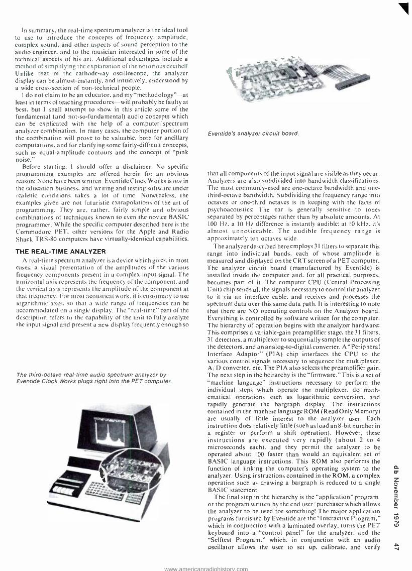
In summary. the real -time spectrum analyzer is the ideal tool to use to introduce the concepts of frequency, amplitude, complex sound. and other aspects of sound perception to the audio engineer, and to the musician interested in some of the technical aspects of his art. Additional advantages include a
method of simplifying the explanation of the notorious decibel! Unlike that of the cathode -ray oscilloscope, the analyzer display can be almost -instantly, and intuitively, understood by a wide cross -section of non -technical people.
I do not claim to be an educator, and my "methodology " -at least in terms of teaching procedures -will probably be faulty at best, but I shall attempt to show in this article some of the fundamental (and not -so- fundamental) audio concepts which can be explicated with the help of a computer/ spectrum analyzer combination. In many cases, the computer portion of the combination will prove to be valuable, both for ancillary computations. and for clarifying some fairly -difficult concepts, such as equal- amplitude contours and the concept of "pink noise."
Before starting, I should offer a disclaimer. No specific programming examples are offered herein for an obvious reason: None have been written. Eventide Clock Works is not in the education business, and writing and testing software under realistic conditions takes a lot of time. Nonetheless, the examples given are not futuristic extrapolations of the art of programming. They are, rather, fairly simple and obvious combinations of techniques known to even the novice BASIC programmer. While the specific computer described here is the Commodore PET, other versions for the Apple and Radio Shack TRS -80 computers have virtually -identical capabilities.
THE REAL -TIME ANALYZER A real -time spectrum analyzer is a device which gives, in most
cases, a visual presentation of the amplitudes of the various frequency components present in a complex input signal. The horizontal axis represents the frequency of the component. and the vertical axis represents the amplitude of the component at that frequency. For most acoustical work. it is customary to use Logarithmic axes, so that a wide range of frequencies can be accommodated on a single display. The "real- time" part of the description refers to the capability of the unit to fully analyze he input signal and present a new display frequently enough so
The third -octave real -time audio spectrum analyzer by Eventide Clock Works plugs right into the PET computer.
Eventide's analyzer circuit board.
that all components of the input signal are visible as they occur. Analyzers are also subdivided into bandwidth classifications. The most commonly -used are one -octave bandwidth and one - third- octave bandwidth. Subdividing the frequency range into octaves or one -third octaves is in keeping with the facts of psychoacoustics: The ear is generally sensitive to tones separated by percentages rather than by absolute amounts. At. 100 Hz. a IO Hz difference is instantly audible: at IO kHz, it's almost unnoticeable. The audible frequency range is approximately ten octaves wide.
The analyzer described here employs 31 filters to separate this range into individual bands, each of whose amplitude is
measured and displayed on the CRT screen of a PET computer. The analyzer circuit board (manufactured by Eventide) is
installed inside the computer and, for all practical purposes, becomes part of it. The computer CPU (Central Processing Unit) chip sends all the signals necessary to control the analyzer to it via an interface cable, and receives and processes the spectrum data over this same data path. It is interesting to note that there are NO operating controls on the Analyzer board. Everything is controlled by software written for the computer. The hierarchy of operation begins with the analyzer hardware: This comprises a variable -gain preamplifier stage, the 31 filters, 31 detectors, a multiplexer to sequentially sample the outputs of the detectors, and an analog -to- digital converter. A "Peripheral Interface Adaptor" (PIA) chip interfaces the CPU to the various control signals necessary to sequence the multiplexer. A/ D converter, etc. The PIA also selects the preamplifier gain. The next step in the heirarchy is the "firmware. " This is a set of "machine language" instructions necessary to perform the individual steps which operate the multiplexer, do math- ematical operations such as logarithmic conversion. and rapidly generate the bargraph display. The instructions contained in the machine language ROM (Read Only Memory) are usually of little interest to the analyzer user. Each instruction does relatively little (such as load an 8 -bit number in a register or perform a shift operation). However, these instructions are executed very rapidly (about 2 to 4 microseconds each), and they permit the analyzer to be
operated about 100 faster than would an equivalent set of BASIC language instructions. This ROM also performs the function of linking the computer's operating system to the analyzer. Using instructions contained in the ROM. a complex operation such as drawing a bargraph is reduced to a single BASIC statement.
The final step in the hierarchy is the "application" program or the program written by the end user purchaser which allows the analyzer to be used for something! The major application programs furnished by Eventide are the-Interactive Program," which in conjunction with a laminated overlay, turns the PET keyboard into a "control panel" for the analyzer, and the "Selftest Program," which, in conjunction with an audio oscillator allows the user to set up. calibrate, and verify V
www.americanradiohistory.com

co v
DiSPLÁVEAALM6DEE SPECTR DECÁLY D MLÁVEZEALMÓI7ÉEpDECÁLiiii1
Figure 1. Sine waves at two frequencies and different levels applied to analyzer input. Characteristics of both signals may be determined instantly (and precise levels gotten from the computer for quantitative analysis. An oscilloscope display of the composite waveform would be difficult to interpret.
operation of the analyzer. Unlike the machine language program in ROM. application programs may he very unsophisticated. For instance. "operating" the analyzer in a
single mode, so that the display continuously shows the input signal. requires a program only 4 statements long. two of which perform the analysis and two that are used for "housekeeping." At the other end of the scale. application programs may be quite complicated, including not only operation of the analyzer, but control of peripheral equipment, data storage on disc and cassette tape. and calculations involving data generated internally and externally. Most of the applications suggested in this article require application programs. either our "Interactive Program." or one written by the instructor. One could add that. depending upon the degree of "computer illiteracy" exhibited by the students. and their desire or requirement to combat it. It might also he advisable to suggest or assign programming problems which combine use of the spectrum analyzer and the computer.
"LESSONS" While the analyzer computer may be used for all familiar
applications and many unfamiliar ones. I am going to limit this discussion to a few examples which may he used to increase the student's knowledge and or aid his sonic intuition. In this highly -subjective field. it would be difficult to say which should take priority.
INTRODUCTION TO AUDIO CONCEPTS VIA THE ANALYZER
The perception of pitch and loudness may be related to the physical concepts of frequency and amplitude with the adjunct of a variable -frequency oscillator and attenuator set. Amongst the phenomena which can be demonstrated are:
The nature of musical octaves and harmonics: The tuning of the oscillator can be varied between, say 400 Hz and 800 Hz, and the tact that the peak of the bargraph has moved by 3 units should he noted. The student is then asked to adjust the oscillator to a frequency another octave higher, without watching the display. Most people will be able to come close without difficulty. Reference to the display will show a vital fact. The frequency has been multiplied by2(the bar above 1600 is now at a maximum). indicating that for the same perceived difference in sound. the absolute change has doubled. R epetition of this experiment with different starting frequencies will bring home the significance of percentages as opposed to absolutes in musical relationships. This simple, almost insignificant, demonstration is extremely effective in explaining this non- intuitive fact.
Figure 2. Same as Figure 1, except the display is loga- rithmic. Comparison between LIN and LOG displays. along with calculations based on the numerical values of the data help elucidate the meaning of decibel.
Another demonstration in this vein isa hands -on proof of the existence of "equal amplitude contours." Here we employ a
(conceptual) application program for the PET. This program will permit the PET to capture a frequency
amplitude data point in response to pressing a key or an external switch closure. In operation. the instructor tunes the oscillator to the various filter center frequencies. (He. not the student. is watching the screen.) The student is then asked to adjust the attenuator until the tone sounds "as loud" as the previous tone. When the student is satisfied with the level, he may press a button (or nod OK if no external hardware is
connected) and the instructor can press a key. The computer takes over now and stores both the frequency and the ampltude data automatically and instantaneously. The procedure is
followed until the frequency becomes so high that it is no longer possible to achieve equal loudness without shattering windows. When the data set is complete. the analyzer firmware converts it to a bargraph showing the ear's frequency response throughout the audio range. It is only slightly- more -complicated to write a
BASIC program to do this procedure with multiple students, saving all the data both individually and as a statistical summary. In fact. with a large enough group. it might be possible to get an indication of the decline in high frequency acuity with age. All of this data can be presented effectively (and even animated. if desired) on the computer screen. Data derived by experiment is usually more convincing than that which is
read (or is the subject of lectures). The experiment might be effectively augmented with a presentation of the effects of listening to loud noise or music over long periods. Temporary threshold shift can be demonstrated by taking data before and after a practice mixing session. (The computer can stor; the first set of data on its cassette drive.)
I began the above paragraph by mentioning an "application program." The evolution of the paragraph simulates the evolution of most programs. You begin with a simple task (taking data for one student), and end up with a relatively complicated one, taking data from a group. performing statistical summaries, storing it, re- loading it, and comparing it with a new set of data to be taken! Fortunately, none of the steps is particularly difficult if attacked logically. Programs, like hardware, benefit from modular construction. Of course. once a set of teaching programs is developed, it may be reused indefinitely.
THE DECIBEL Judging from the number of articles appearing on the subject,
it would seem that the decibel is either the most misunderstood or most abstruse concept this side of relativistic time dilation.
www.americanradiohistory.com

D15PLtiYELREALT4ßËE®99a 9ECÁLilital
(, ;.li1Y+ilart] - - _ `ail -1.
Figure 3. "Pink Noise "applied to the input of the analyzer. This ragged graph represents a "snapshot" or single analysis. Normally the eye integrates the data over readings to obtain a "flat" line.
Why this should be so I don't chose to guess. but the spectrum analyzer should make explanations a bit easier. The PET, analyzer combination has the capability of displaying a spectrum in either a linear or logarithmic mode (and of switching simultaneously between modes). With proper signal sources (such as two independent sine -wave sources, and perhaps a few noise sources as well), one can demonstrate such fundamentals as linear- versus -logarithmic voltage ratios and coherent and incoherent addition of signals. Remember that the mathematical capabilities of the computer allow the student to simultaneously experiment with real -world signals and perform calculations upon the data he measures and the results he derives.
Another subject (difficult, and with far- better reason), is the interaction between physical spaces filled with arbitrarily - shaped objects, and sound generated and reverberating within such spaces. Analytical solution of such problems is. with minor exceptions, impossible even with high -speed modern computers. Despite this fact. studio workers of all persuasions are called upon to function in this environment, and any steps that can he taken to aid them in developing their general understanding and intuition regarding everyday problems like microphone placement and the physical arrangement of sound sources must he classified as one of the most important tasks facing the instructor. To this end the spectrum analyzer, a noisy source. and a few application programs will find use.
ACOUSTIC MEASUREMENT Before continuing. I should point out a few additional
capabilities of the analyzer: built into the ROM firmware are the machine language routines necessary to do "ensemble averaging." This k a process by which the results from successive analyses are added together. frequency cell-by- frequency cell. The result of this process is to drastically reduce the statistical uncertainty of a measurement, by averaging the readings of many measurements. Because noise sources typically hate significant variations in their low frequency output oser short intersals, analyzer users are accustomed to unsteady display s in the lower octaves. While the eye and brain can integrate a moving display to a reasonable extent, it is
certainly better to has actual numbers to work with and these the averaging process provides. The other capability is to substitute BASIC routines in certain cases for the machine language routines resident in the ROM. Thus, if the user does not wish to perform a complete spectrum analysis. he can write routines to analyze the results from a single filter or group of filters.
With this explanation out of the way, the procedures and experiments are left pretty much in the hands of the instructor. An obligatory one is "room tuning." in which the room is
Figure 4. "Pink Noise" applied to the input of the analyzer results in a much flatter graph after multiple averages. Because the scale is linear, the actual roughness is less than ±1 dB.
excited with pink noise and the "room curve" is observed on the analyzer screen. Of course. most classrooms will he very poor acoustically, but this doesn't affect the validity of the experiment. A quick variant to give insight into absorption is to save this curve in the computer. temporarily have everybody leave the room. and take another curve. The computer can then rapidly switch between curves while everybody tries to understand why they are different. If a graphic equalizer is
available. it would also be instructive to attempt to flatten the room curve. Of course, the room may be so poorly designed that the attempt will fail. or. if it succeeds. the "equalized "room may well sound worse than when unequalized. This brings home quite quickly the importance of having proper physical design for acoustic spaces.
The previous experiment used the averaging capability to increase the accuracy of the measurement. The next uses the capability for selective analysis to perform an amplitude- versus-time measurement at a given frequency.
REVERBERATION MEASUREMENTS I he l'E I computer has a built -in clock (which measures in
"jiffies." 60 to the second). This allows programs to determine how longa particular procedure has taken. to print out the time. etc. An always- interesting characteristic of acoustic spaces is the reverberation time or the length of time required for a sound impulse to decay to a fraction (usually -60dB) of its original value. Even more interesting is this characteristic in individual frequency bands. since the capability to vary these parameters leads to a more "natural "sounding reverb than does. say. a long reverb time due to a horrendous resonance at 500 Hz! The PET analyzer combination permits a complete set of such measurements to be made automatically, even to the extent of controlling the sound source and printing the results. In the teaching environment, this allows rapid experimentation with different techniques for reducing (or creating) resonances. and giving the student a feel for the characteristics of different spaces. such as "live" and "dead" portions of rooms.
There are many other instructional applications of the real -time analyzer, and the computer itself is becoming more nearly ital as a teaching tool. Combining the two instruments provides an opportunity to familiarize the student with many new and some. fairly difficult concepts effectively. The computational capabilities of the analyzer permit data to be presented in a manner that aids intuition and auditory experience and thus provides immediate reinforcement of lessons that might otherwise be lost. The complexity of interrelating the audio and video inputs to the human brain is substantially reduced by using a computing spectrum analyzer. and this aids the student in integrating new information for his future use. CD
www.americanradiohistory.com

DAVID L. HAYNES & JOHN M. BRENNAN
A New Digital Delay System
Recent advances in digital technology now make it practical to use digital delay lines in primary - channel applications.
THE SUCCESSFUL CREATION of a master disc from a care- fully- produced master tape is a key process in assuring the overall quality of the final product, the phonograph record. A great deal of specialized equipment is neces-
sary to insure a high -quality master disc: among this equipment is the variable -pitch lathe.
A variable -pitch lathe has a mechanism for varying the groove spacing for the cutting head. Using this type of lathe. the pitch becomes dependent upon the character of the program material. A variable -pitch lathe requires two audio signals: the original "preview" signal. sent to a computer which con- trols the pitch -adjusting servo system. and. a delayed "pro- gram" version of the original signal, actually cut onto the master disc. The purpose of the delay is to allow the pitch to be properly adjusted by the time the program signal reaches the cutting head. FIGURE 2 shows a block diagram of a typical variable -pitch disc mastering system.
This variable -pitch feature allows an increase in the program length, and or the dynamic range. that can be put onto a disc. Since the preview signal controls the pitch (lines per inch) of the grooves engraved by the cutting head, groove spacing becomes a function of the amplitude and dynamics of the source ma- terial. For low -level passages. the pitch controller will make the grooves closer together. For higher -level passages. the grooves will be farther apart. This allows optimum packing of program material onto a record side. Variable -pitch also provides another 2 -to -3 dB "hotter" recording level thus. dynamic range -than would be possible for the same amount of program material using a constant -pitch lathe.
THE OLDEN DAYS The variable -pitch lathe is by no means a new device. In the
late 1940's. custom variable -pitch adapters could be seen in some mastering suites. Around 1951. the Reeves- Fairchild
David L. Harnes & John M. Brennan are engineers in
o the Audio Engineering Department at Ampe.v Corporation. Redwood City. CA.
margin control -an adapter usually fitted to Scully' lathes -was marketed. This Scully Reeves- Fairchild set -up became the first widely used variable -pitch lathe. To produce the required delay, several methods have been used. The most common method used today is a special tape recorder with two playback heads. Between the two heads. a set of tape guides provide a path for a tape loop. If one were cutting an LP lacquer using a 30 in sec.
master tape and the Scully lathe (which requires one revolution of delay). 54 inches of tape would be required between the two playback heads. Complicated guide schemes required for this excess amount of tape open the door for possible degradation of wow and flutter characteristics. Also. most preview transports do not accommodate the 14 inch reels which may be required at 30 in sec. As a result. slower tape speeds arc often used for the master tapes.
Of course. direct -to -disc recordings (by definition) cannot use this method. therefore a highly experienced lathe operator must be present at all times. By reading the score he anticipates program content. and manually adjusts the lathe pitch. This can be a tricky situation because if he guesses wrong an overcut can occur and the session must be re -done.
The advent of digital recording has created its own problems. Because of the intimate head -to -tape contact required. complex guide schemes. as mentioned above, are very difficult to imple- ment. Therefore. one solution currently used is to record the program material onto two channels of a four -channel digital recorder. The program is also stored in a computer. read out the required delay time later. and recorded onto the other two channels. This method of preview requires a knowledge of the type of lathe to he used later. and is only valid for one cutting speed. In other words, a single four channel tape could not be used to cut 33 and 45 rpm versions of the same tune.
WHY ANOTHER DIGITAL DELAY UNIT? It became apparent that a more -versatile form of previewing
for disc mastering could he developed. At Ampex. after review- ing the economic trends of digital hardware. and the company's own research into digital audio technology. it was felt that an ideal solution would be a digital delay system, providing accurate analog-to-digital-to-analog conversion, appropriate delay, and optional digital inputs and outputs.
www.americanradiohistory.com

Seated at a Neve disc -mastering console at Filmways/ Heider studios, engineer Phil Cross oversees a tape -to- disc mastering session. Between the lathe and an Ampex ATR -100 is the new Ampex ADD -1 digital delay system.
There are many types of digital delay units currently avail- able. These are secondary -channel systems- excellent for providing room ambience enhancement and for adding special effects to specific recorded tracks. However, a primary -channel delay, which can be inserted into the main audio line, requires electronics comparable to that of a state -of- the -art digital tape recorder.
For a system like the Ampex Digital Delay, degradation of the signal is not dependent upon the delay time (for the same reason that the degradation in a digital tape recorder is not dependent upon the tape). Once the signal has been digitized. the length of the delay depends only upon the amount of memory available to store the digital samples. This type of system is also appealing from a standpoint of versatility, be- cause it is compatible with any type of audio source. This means that the 1/2-inch two -channel tape format, as well as direct -to- disc albums, can take full advantage of the added dynamic range and increased program material possible with a variable - pitch lathe. The delay required for preview using a half -speed mastering system is also programmable and a real -time bandwidth of 20 kHz or 40 kHz is possible.
WHAT'S INSIDE? FI(it RF. 3 shows a block diagram of the ADD -I. Analog
signals enter by way of a balanced line input where they go through an input low -pass (anti -alias) filter, a sample- and -hold. and an analog -to- digital (A/ D) converter. where the signal is
digitized. The digital representation of the sample is then stored in memory for the desired length of time, recalled, and passed through a digital -to- analog (D A) converter, a "de- glitcher," and an output low -pass (reconstruction, or anti -imaging) filter. The "system control" oversees the system and generates the timing as well as doing the memory management.
Because the ADD -1 is a digital system requiring A/D conversion, the analog signal must be sampled, and then held for a finite amount of time. This hold -time must be long enough to allow the A D converter to complete its conversion. The sample- and -hold can be considered to be a simple analog multiplier. As such, the original frequency, the sample frequency, its multiples, and all the sums and differences would be present at the output of the sample- and -hold. As an example, if a IO kHz sine wave is sampled at 50 kHz, signals at IO kHz,40 kHz, 50 kHz, 60 kHz. 90 kHz, 100 kHz, 110 kHz, etc. will all be generated. This is shown in FIGURE 4. The frequency spectrum of a passage of music before and after sampling is shown in FIGURE 5. FIGURE 6 shows the time -versus- amplitude response of the same passage of music. Because of the lowest -order difference frequency (sample frequency minus original
frequency) generated by the sampling process, no frequency applied to the sample- and -hold should exceed half the sampling frequency. Otherwise a false component, known as an alias frequency. will be generated. Thus, an input low -pass filter. usually called an anti -alias filter. is required. This type of filter can have a profound effect upon the overall sound of the system, and an appropriate compromise between aliasing. group delay distortion, harmonic distortion and noise generation must be made. The above distortions are directly related to the cut -off slope of the filter. Because of this. the sampling frequency generated by the internal master clock was chosen to be 50 kHz. This allows the band between 20 kHz and 25 kHz to be used for a reasonable filter roll -off.
The sample- and -hold, being an analog device. does not quantize the audio signal. The value it holds is dependent only upon the amplitude of the signal at the instant it is sampled.
The A; D converter has a finite amount of numbers which it can choose to assign to that value. In the case of a I6 -bit converter (the type used in the ADD -I ). the amount is
65536(216). The process of the A/ D converter choosing the value closest to the one held by the sample- and -hold, and giving it a binary representation. is known as quantizing.
Upon completion of the A/ D conversion process, the digital representation of this sample is stored in a memory location. The memory is addressed in sequential order, starting at the beginning of memory (location 0), and extending to the memory location that corresponds to the desired time delay. Therefore, if one second of delay is desired (using a sample frequency of 50 kHz), samples would be stored in memory starting at location 0 and extending to location 49.999. Once the final location is reached, the process is repeated. When a
location is addressed, the sample stored in the memory location is sent to the D, A converter, and a new sample from the A/ D converter is stored in the same memory location. Thus, the amount of delay is determined by how much of the available
BUILDING A RECORDING STUDIO?
Make us your first call.
Audiotechniques (203) 359 -2312
We're not only the biggest, we think we're the best, by far! We've been building studios for nearly eight years and have more years of com- bined professional audio engineering experience than we like to
admit. Initial planning, financing, designing, equipment installation, maintenance ... they're all our business. If your business is record- ing, you should be talking to us.
Circle 39 on Reader Service Card
u,
www.americanradiohistory.com

m
STUDIO MUSICIANS
DAD SESSIONSP
ADD I
DELAV
DISK CUTTING
LATHE
LATHE SE VO
COMPUTER
PASTE IL LACQUER
Figure 2. Disk Mastering system block diagram.
memory is used. After the desired time delay, the sample is
recalled from its memory location and sent to the Di A converter.
"DE-GLITCH ING" During the conversion process. switching transients can
occur in the output D, A during the settling time. These transients. or glitches. are removed by the de- glitcher. The de- glitcher is similar to a sample- and -hold, since it must acquire a
sample from the D A. after the D A has settled. and hold it until the next sample is available. Because the output of the de- glitcher is exposed to the analog output during those sample - and -hold times, the de- glitcher must be fast enough not to induce slew -limit distortions, while at the same time must be quiet enough to preserve the dynamic range of a I6 -bit digital system. After the signal is de- glitched. the higher -frequency components shown earlier are still present. These high - frequency components must be removed. for they may cause distortions in subsequent analog equipment due to possible slew -rate limitations. Therefore, an anti -image filter with a cut- off at 20 kHz is used after the de- glitcher. Finally, the de- glitched, filtered signal appears at the system output, as a
delayed replica of the input signal. The system control is the coordinator of the entire process.
It is a micro -programmed controller, similar to the type used in many modern computers. The function of the system control is to generate the appropriate timing for the system, manage the memory and oversee the distribution of data within the system. This circuitry also contains the information about how much delay the user requires and uses the memory accordingly. The master clock generates the signals which provide the timing for the digital logic in the system and also generates the sampling clock (which is crystal referenced).
For applications where a sample clock other than that internally generated is desired, the ADD -I provides an external sample rate input jack. The electronics in the system will automatically synchronize with this clock and adapt the system to maintain and display the correct amount of delay.
The system can also interface with other digital audio equipment via a serial digital input and output. This allows digital data (from, say, a digital tape recorder) to be delayed without having to go through an extra conversion process.
HOW GOOD IS IT?
Whenever an analog signal is sampled and converted into a
digital bit stream, two types of distortions occur. The first is dependent upon how many samples are taken per second. This sets an upper frequency limit for the signals which can be accurately reproduced. The other type of distortion consists of how fine the amplitude of the signal is divided or quantized. In a
properly- designed system, this determines the dynamic range. Other types of distortion occur in less- than -ideal systems.
Our old friends, harmonic and I.M. distortion are still present. There are, however, some new ones to be on the lookout for.
One of these is non -linear phase shift with frequency, com- monly known as group delay distortion. The amount and char- acter of the phase shift varies with the type of filters being used.
Another distortion occurs during the sampling process. Frequency components which are seemingly unrelated to the original frequency appear. These so- called convolved frequency components come from harmonic distortion in the sample -and- hold and de- glitcher, which are aliased down into the audio band. (Remember. the sample- and -hold and de- glitcher come after the anti -aliasing filter.)
FIGURE 7 shows the specifications for dynamic range and total distortion -plus -noise for an ideal digital system. The dynamic range of any n -bit system can be determined by the following equation:
X dB = (20 log 2") + C
C is related to the power distribution of the signal. the bandwidth of the filters and the sample frequency of the system. For most audio systems, this number is between 2 and 4.
Because of present technological limitations, digital systems available today do not meet these theoretically -ideal specifications. Therefore, any digital device to be used within a primary channel should be very -carefully investigated.
OTHER APPLICATIONS Of course, the Ampex Digital Delay can be used for any
application where a high -quality delayed signal is necessary. Truly- transparent delays can be used to provide the acoustical time difference necessary for a properly- designed P.A. system for large auditoriums or concert halls. Slap forward. unattainable without degradation before. is now easily possible.
Figure 3. ADD -1 system block diagram.
ONeu ISS
FILTER
MASTER CLOCK
iwTEK
CONTRM OL
D
DIGITAL
RECEIVER
M RV
DIGITAL DATA
MANS -
ISSION
1
www.americanradiohistory.com
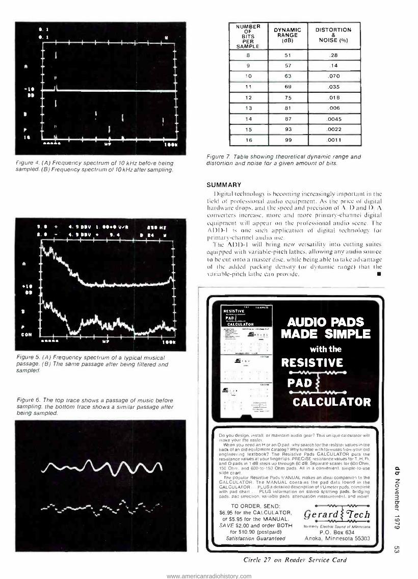
. 1
I. I
A
I t1115sl Y1
Y
Figure 4. (A) Frequency spectrum of 10 kHz before being sampled. (B) Frequency spectrum of l0 kHz after sampling.
Figure 5. (A) Frequency spectrum of a typical musical passage. (B) The same passage after being filtered and sampled.
Figure 6. The top trace shows a passage of music before sampling, the bottom trace shows a similar passage after being sampled.
. r.+ .. -'; ,
NUMBER OF
BIT S BITS PER
SAMPLE
DYNAMIC RANGE
(dB)
DISTORTION &
NOISE ( °ro)
8 51 .28
9 57 .14
lo 63 .070
11 69 .035
12 75 .018
13 81 .006
14 87 .0045
15 93 .0022
16 99 .0011
Figure 7. Table showing theoretical dynamic range and distortion and noise for a given amount of bits.
SUMMARY I)igital technology is becoming increasingly important in the
field ul protes.iunaI audio equipment. As the price of digital hard tare drops. and the speed and precision of A I) and I) A converters increase. more and more primary- channel digital equipment will appear on the professional audio scene. The ADD-I is one such application of digital technology for primar\ -channel audio use.
The ADD-I will bring new versatility into cutting suites equipped with variable -pitch lathes, allowing any audio source to he cut onto a master disc, while being able to take advantage of the added packing density (or dynamic range) that the variable -pitch lathe can provide.
RESISTIVE
PAD
CALCULATOR
®.,,. AUDIO PADS
MADE SIMPLE with the
RESISTIVE
PAD
CALCULATOR
Do you design. install. or maintain audio gear? This unique calculator will make your life easier.
When you need an H or an O pad. why search for the resistor values in the back Of an Old equipment catalog? Why fumble with formulas Irom your old engineering textbook? The Resistive Pads CALCULATOR puts lb, resistance values at your fingertips. PRECISE resistance values for T. H and O pads in 1 dB steps up through 60 dB. Separate scales for 600 O 150 Ohm. and 600 -10 -150 Ohm pads. All in a convenient. simple- to -u,.- slide chart.
The popular Resistive Pads MANUAL makes an ideal companion to o
CALCULATOR. The MANUAL contains the pad data found in n CALCULATOR ... PLUS a detailed description of VU meter pads. comp with pad chart ... PLUS information on Stereo Splitting pads. bnd9 pads. pad Selection. variable pads. attenuation r',ea,n m..,1t and n,,r.
TO ORDER, SEND: $6.95 for the CALCULATOR,
or $5.95 for the MANUAL. SAVE $2.00 and order BOTH
for $10.90 (postpaid) Satisfaction Guaranteed
forment' E(ecrr,c Sound of Minnesota
P.O. Box 634 Anoka, Minnesota 55303
Circle 27 on Reader Service Card
www.americanradiohistory.com

DAVE RUBENSTEIN
Understanding Magnetic Tape Specifications Part II A review of the electro- acoustic properties of magnetic tape -how they are derived, and what they represent in terms of tape evaluation and performance.
WTIEN COMPARING ONE TAPE with another it is im- portant to compare them under the same circum- stances. In other words, you must compare apples with apples, not apples with oranges. Simply
stated, the tape speed must be the same, the record track width the same, the record level must be the same, and the equaliza- tion must be the same. Only when these four factors are equal can one compare measurement data. Furthermore, in order to properly test any tape, first make sure that the machine is optimized for that tape, starting with the bias.
In order to bias a machine, one must look at the specifications given by the manufacturer as to the sensitivity reduction of a given signal. In the case of the graph in FIGURE 1, that signal is 10 kHz (at 15 in/ sec.) The method for biasing a tape is to feed the required signal into the machine at a low level, place the machine into record and monitor the playback on the VU meter. Increase the bias until a maximum level is achieved on
Dave Rubenstein is technical manager. Magnetic Tape 10 Department at Agfa - Gevaert. Inc.
the meter; then increase the bias further until the reduction of the applied signal is equal to the specifications supplied by the manufacturer. This method of sensitivity reduction to arrive at the proper amount of bias current can be visually depicted on the graph. Looking at the E 10 kHz curve, find the peak and then -given the specification of a recommended 31 dB sensi- tivity reduction -count this amount downwards from the peak, and arrive at +2 d B of bias current, which is shown at the bottom of the graph. It is important to note that sensitivity reduction is the fall -off in frequency response of the tape, not an actual reduction in bias current. For example, when someone com- ments that one tape requires I dB more of bias than another, they are speaking of increasing the bias current, not of reducing the applied signal level to achieve the proper bias setting.
The second specification normally given is the deviation of the recommended bias from the bias setting of a DIN (Deutsche Industrie Normen) reference tape. This German Industrial Standard is published by the German Standards Committee (DNA, Deutscher Normen- ausschus), and is used as a worldwide zero -reference point. The DIN reference tape is PER 525, manufactured by Agfa- Gevaert AG. The DIN committee has defined this tape as having zero (0) reference bias. Therefore, all other mastering tapes are related to this tape, and the graph shown in FIGURE 1 depicts a tape with a bias of +2 dB over the DIN standard.
At this point, it is important to note that for any given tape there is a manufacturer- recommended bias, and that no matter
www.americanradiohistory.com

what speed or what operating level the consumer chooses to use, the amount of bias current is always the same; only the method to derive the amount of bias is varied. It is also impor- tant to note that the width of the record gap is also a factor which will vary the method used to derive the proper amount of bias.
Due to an effect known as self- erasure, the high -end response decreases as the bias increases. (The bias current begins to erase the tape- -high frequency first.) The narrower the record gap, the greater the sensitivity reduction necessary to achieve the proper bias. The wider the record gap, the less sensitivity reduction necessary. To state it more fundamentally, a record head with a narrow gap is more efficient than one with a wider gap.
The next factor, and an extremely important one at that, is third harmonic distortion (thd). It is given as a figure in percentage of the total signal. Third harmonic distortion, as we discussed previously, is bias -dependent. The greater the bias, the lower the distortion (up to a certain point). After that point, the law of diminishing returns takes place, and distortion once again begins to increase. Hence, careful setting of the bias, for a
low point in the distortion, is very important. On the graph the curve thd = 320 is the curve for low frequency distortion. The measurement can be read on the vertical percentile line to the left of the graph. Looking at the graph, we notice that the minimum point on the distortion curve is the exact point of 2 dB of bias current. Therefore, an alternate method of biasing the
Talk IS
cheap. Here are some of the actions
your company can take to prevent the suffering caused by poor parenting patterns
and child abuse.
We want to stop the hurt.
We are enclosing a tax -deductible donation in the name of our company. We want to help. Please call our company and tell us what you're doing to stop the hurt of child abuse in our community. We will plan a day for employees' children to visit our place of work to learn what we do and why.
*prevent chid Buse. wriftu M.
, .. ., &ONO _ v
L J a Public Service Of This Magazine
IDIM S Tt.e Advertising Coune.I
Perfect Levels
ES 214 Dynamic Audio Level
Indicator made especially for the broadcaster
and recording engineer
Features: Peak Audio Levels or Apparent Loudness
(Fast Averaging) Uses Standard V.U. Scale High Brightness, 3 -Color Display Transformer Isolated Input Unregulated "Single- Supply" High Input Impedance and Sensitivity Low Cost
There are a number of Audio Level Indicators using L.E.D. bar graphs on the market today. Their acceptance is becoming widespread due to obvious advantages. However, the ES 214 gives you more: Transformer Isolated Input others consider too
costly: A Power Supply Regulator on the circuit board, so you can use any unregulated D.C. voltage from + 15 to + 35 while others require dual supplies: The Standard Scale so you don't have to adapt to new numbers; and, the ability to select Peak
Responding Mode or a special Fast Averaging Mode to approx- imate Apparent Loudness.
Get a handle on your levels with the ES 214
$105.00
(213) 322 -2136
142 SIERRA STREET EL SEGUNDO, CA 90245
Circle 57 on Reader Service Card
www.americanradiohistory.com

m tn
tape (if one had the proper equipment to measure distortion), would be to bias for minimum distortion. The percentage distortion at the proper bias point is 0.2 percent; an excellent distortion figure.
The next point to be looked at on the graph is the curve marked MOL (thd = 3 %). This stands for Maximum Output Level (the highest output one could receive from the tape, given a maximum of three percent third harmonic distortion using a i kHz tone. The point of maximum output level is also bias - dependent. In the case of this graph, the maximum output level is more -or -less at the optimum point of bias. Note that at the bias where you found the minimum thd, the MOL curve for 3% thd flattens out, and the 1% MOL curve reaches its maximum.
If the MOL 3% (or, sometimes 5 %) thd curve reaches maximum and then drops more than 1 dB without rising again, you can assume that the record head is saturated by bias and record current, and you are measuring the distortion of the head.
1 The MOL 1% thd curve must follow the thd curve at the reference level; that means when thd at reference level shows a minimum, MOL I% thd has its maximum. One can determine the maximum output level by counting how many dB above the reference level the graph depicts. In order to fully understand maximum output level, one must first understand the term reference level.
The reference level represents a working point so that the user can receive the most output from the tape and still keep distortion at a practical minimum. Or, to coin a phrase, "the hotter, the better." However, if the record level gets too hot, the distortion increases due to non- linearities in the remanence curve (which was discussed in Part I). Hence, reference level and record level are synonymous, and the tape manufacturer will recommend a reference level for the given tape. Therefore, when we compare maximum output level from one tape to another, make sure that the two tapes are measured from the same reference level. In the graph provided, the maximum output level at the point of optimum bias is +10 dB (for 3% thd). According to the graph, the reference level is 320 nanowebers- per -meter (nWb /m). A nanoweber is a measurement of magnetic fluxivity. To put it more plainly, it means that one would set the record level high enough to achieve an output of, 320 nWB reference fluxivity from the tape (fixed with a reference tape).
The maximum output level at 3% thd is measured with a I
kHz tone. If the maximum output level was measured at a different frequency, another result would occur. Therefore, an industry standard specifies that maximum output level at 3 per cent is always measured at I kHz.
The next two points deal with relative sensitivity and three different frequencies; 1 kHz, 10 kHz, and 14 kHz. Relative sensitivity is measured with a given frequency with a constant record current which results in a replay voltage 20 dB below reference level. In simpler terms, a relative sensitivity is a measurement to determine if the tape truly puts out what is fed in. As you can see by the graph, sensitivity is extremely bias - dependent. Earlier, we used the sensitivity curve of IO kHz to bias the machine. We can now look at the difference between the sensitivity curve of a I kHz tone and those of the 10 and 14 kHz tones. Until recently, some tape manufacturers have recommended that their tape be biased with a I kHz tone. In reality, this is not very practical, because the slope of the I kHz tone curve is not very steep, and therefore it is difficult to find the peak on a VU meter. However, when we use a 10 kHz tone, the slope is steep and the peak can be found easily. Hence, with a 10 kHz tone, we can bias a machine with greater accuracy. Relative sensitivity of the three tones previously mentioned can be seen on the graph as E 1, E 10 and E 14 kHz. Many times a
Figure 1. Graphic representation of electro- acoustic properties of magnetic tape.
v = 39. 0tre 15 InJs t = illI1 _ d1OPIa U_,
10
4
10- 20
e
2
Ase
A,yY
A., DP e10
A,r BP 320
mol (thd = 3%)
mol 10 kHz
mol (thd = 1%)
mol 14 kHz ref level 320 nWb
E,w response I kHz
1 40
0.6
0.3 .- 60
0.2
01 so
E 11111111111111ZE
response 10 kHz
response 10 kHz reference
response 14 kHz
K,510 distortion the = 510 nWb
K.320 mm
MR
RO t1s1 6.3 A.n
RO HAD ,mm
-4 -2 0 + 4 " 4/!4 -BP ée
distortion thd r 320 nWb
modulation noise
noise weighted 0.04
noise weighted 0.248
www.americanradiohistory.com

tape manufacturer will give a sensitivity specification relative to a reference tape. This is perfectly acceptable if we know the sensitivity of the reference tape. (If all tape manufacturers used the same reference tape, and the test methods were identical, the relative sensitivity measurements could be directly compared.) One can see from the data that, at certain frequencies. the tape has a higher sensitivity than the reference tape, and at other frequencies it has a lower sensitivity. As far as sensitivity is concerned, the higher, the better. One can see by the sensitivity curves that the bias adjustment can greatly affect the output of the tape. This is another point to make in favor of proper bias adjustment. If the bias is incorrectly adjusted, further equalization may be necessary. therefore adding more noise.
To delve a little further into what really happens on the tape to produce a sensitivity specification, let's consider three different parameters. The first is the quantity of magnetic particles within the same area of the tape. The greater the number of particles in the area (track width times coating thickness). the greater the low frequency output will he. (Shorter wave lengths do not contribute to the output from the depth of the coating: only longer wave lengths will add to the output from the lower sections of the coating.)
The second parameter is the squareness factor, which was discussed earlier in the section on hysteresis curves. This depends on the orientation of the oxide particles. If all the particles have different orientations, the squareness factor is approximately 50 per cent. The remanent magnetization is only 50 per cent of saturation. Modern tapes have a squareness factor of approximately 80 to 90 per cent of saturation.
The third and final parameter is surface roughness. This factor greatly influences short wave length (high frequency) response, due to distance attenuation, which was also discussed previously.
The curve right below the third harmonic distortion curve is the curve of modulation noise. This curve is also extremely bias - dependent, as is depicted on the graph. If a tape is under -or over -biased even as little as 2 dB, the modulation noise becomes unbearable. Another method of biasing the tape is to bias for the minimum point of modulation noise. According to the graph, the minimum point of modulation noise is the exact point of optimum bias at 15 in/ sec. This biasing technique works for 15 in sec., but not at any other speeds. It is also dependent upon the record head. The faster a tape runs, the greater the modulation noise, due to the speed at which the imperfections in coating pass across the head gap.
The next topic concerns a property of magnetic recording which is one of the greatest deterrents of an analog system. We are, of course, speaking of random noise -the swish or hiss that is heard underneath the program material. Noise is created from random charges of the particles on the tape. The size and shape of a particle can have a large effect on the noise. The smaller the particles, the lower the noise: however, print - through becomes worse as particles get smaller. It is extremely important that one records at a fairly high level in order to magnetize as many particles as possible in the oxide layer. If many particles are left untouched by the magnetic field from the gap, the noise will be that much greater to the ear. The more particles the magnetic field influences, the more the noise is masked. The noise, as one can see from the graph, is not bias dependent and is a property of the given tape. The noise is, however, track -width dependent. As you increase the track width from I mm. to 2 mm. the noise voltage increases by 3 dB. But the output voltage doubles, because twice the number of particles pass across the head. Hence, the output voltage rises by a factor of 2, which equals 6 dB. In other words, the output voltage is twice as high, while the noise is increased by only one - half as much. Therefore, the wider the track width, the better. Hence, a half- track machine will have a better dynamic range than a quarter -track machine. Furthermore, a I6 -track
4 CHANNEL
WC MIXER
PM - 1
S140.00
10 BAND
GRAPHIC
EQUALIZER
AC - 1
S125.00
3 BAND
TONE EQUALIZER
WITH THIS AD LIMIT THREE UNITS
OFFER EXPIRES JANUARY 31. 1980
SE SCOM IATRODUCES ITS AIM PRODUCTS
SM- t
$125.00
ACTIVE AUDIO
DA 4 CHANNEL
Sc-1 5125.00
I(/
z
0 0 6
OM - 1
$225.00
3 BAND PARAMETRIC
E OUALIZER
GO - 1
5125.00
ADJUSTABLE
ACTIVE CROSS
OVER
TE - 1
5100.00
STEREO HEADPHONE
AMPLIFIER
ADA - 1
5125.00
STEREO COMIIINER
PHONO & LINE
PRO FEATURES AT SEMI -PRO PRICES
SHOWN RACK MOUNTED OR CAN BE USED INDIVIDUALLY
AC POWERED OR BATTERY OPTIONAL
SEND FOR YOUR FREE COPY OF 0 UR NEW 1979 - 80 CATALOG
SESCOM,INC. INTERNATIONAL CORPORATE OFFICES
RETAIL SALES DIVISION
1111 LAS VEGAS BLVD. NORTH
LAS VEGAS, NV 89101 U.S.A.
(702) 384 -0993 (800) 634 -3457
TWX (910) 397 -6996
Circle 55 on Reader Service Card www.americanradiohistory.com

co
4
12 - o
2
ö Ó a
m6 v
8
TR
2 3
2 TR
4 5 6
FULL TR
Track width
mm
The signal to noise ratio of a magnetic recording Is dependent, amongst other things, upon the track width. This inter- dependence is figured in the diagram opposite. The signal to noise values stated in this data sheet are given for track widths of .248" and .04" respectively. In practice however other track widths are used. In order to determine the S/N value, one must add the value obtained from this diagram to the S/N value for 1 mm of track width. Should a signal to noise ratio of a desir- ed output be specified, the difference in level relative to the DIN reference level should be taken into account. Signal to noise relative to maximum output with a distortion level of K3 - 3% (RGA) is specified according to DIN 45 512, sheet 2.
Figure 2. Variation of signal -to -noise ratio in relation to track width.
machine using 2 inch tape would have a better noise characteristic than a 24 track machine using 2 inch tape due to the fact that each track width is wider.
FIGURE 2 depicts the relationship between track width and noise. Utilizing this graph, we can determine the noise of a given tape in conjunction with the track width that the machine is working with. Shown on the graph are the European standard track widths for quarter -, half -, and full- track. The values obtained from this graph must be added to the value obtained for the noise of a 1 mm. track width.
SIGNAL -TO -NOISE RATIO After covering the subject of noise. the next obvious
specification to be dealt with is the term signal -to -noise ratio. or dynamic range. Dynamic range is a simple calculation. made by adding the weighted noise characteristic to the maximum output level at three per cent third harmonic distortion. Therefore, at 15 in sec.. if the noise is 68 dB and the maximum output level is +10 dB. the signal -to -noise ratio is 78 dB. This can be calculated using the figures supplied or by counting dB on the graph. Signal -to -noise ratio or dynamic range is the range in which one can record, from the quietest, lowest signal to the loudest, highest signal. Below the noise floor one could not hear what was recorded and above the MOL peak, the signal would be distorted. Therefore, the signal -to -noise ratio expresses the effective working range of a given tape. The wider the ratio, the better, because one could record at a higher level with low distortion and record tones at a lower level and they would still be discernable above the noise floor.
PRINT -THROUGH Print -through has plagued recording engineers ever since the
onset of magnetic tape recording. Print -through is the pre- or post -echo heard before and after a recorded tone. It occurs after a recording has been made and the tape is wound on a reel. Each layer of tape has adjacent layers, full of tiny magnetic particles, which act upon the particles in the neighboring layers. As was discussed earlier. the particles on the tape are not all of the same size. Larger -size particles have greater coercivity than the smaller ones. Therefore. if you record a tone on the tape and the adjacent layers are blank, the larger particles on the recorded portion of the tape will influence the smaller particles on the unrecorded section of the tape. creating a similar magnetic pattern on the adjacent layers. These similar charges result in a tone exactly the same frequency as the one originally recorded, only at a much lower level.
Print -through may be heard on recorded, as well as unrecorded, segments of tape. Usually. it is the pre -echo that is
heard and it sounds as if, for example. the downbeat of the orchestra occurs very softly, shortly before the real downbeat. The loudest print- through occurs on that segment of tape whose magnetic coating comes in direct contact with the loud segment of recorded tape. On standard -winding transports. this means the greatest print- through radiates outward, (away from the center of the reel). Tapes stored tails -out will therefore have greater post -print. Heads -out storage will produce greater pre- print. The difference between the two is approximately I -to -2 dB. Print -through is wave- length dependent. and is obviously an unwanted characteristic. There are certain ways of reducing its effects. Because the printed tone is recorded without a strong
www.americanradiohistory.com

Figure 3. A typical magnetic tape specification sheet. Represented are the electro- acoustic and magnetic properties for Agfa- Gevaert PEM 468 Mastertape.
TECHNICAL DATA ELECTRO- ACOUSTIC PROPERTIES Unit
MEASURING CONDITIONS:
Tape speed ips 30 15
Track width mm 6.3 6.3
Tape flux per 1 mm track width for reference level pWb 320 320
I. Sensitivity reduction for 4E kHz 3f '2
recommended bias AE kHz dB 2
2. Deviation of the recommended bias from the bias setting of the DIN reference tape ivAiivB dB -2 : -2
3. Third harmonic distortion K, % 0.15 0.2
4. Maximum output level (THD 3%) Av, dB ,f-10 X10
5. Relative sensitivity at 1 kHz E, kHz dB 1.5 1
6 Relative sensitivity at 10 kHz E,, kHz dB 1
Relative sensitivity at 14 kHz E,, kHz 0.5 10.5
7. Maximum output level at 10 kHz A,, max dB -+ 0.5 Maximum output level at 14 kHz A max dB +2 r 0.5
8. Modulation noise. MR dB St 54
9. Noise weighted RG dB 66.5 68
10. Signal to noise weighted RGA dB 76.5 78
11. Print -through 60 58
12 Signal to erase ratio - 70
13. Uniformity at I kHz a. within a reel S -'-0.25 b. roll to roll -'0.5
MECHANICAL PROPERTIES
14. Coercivity il-lc Oe 380
15. Retentivity Brs G 1060
16. Residual saturation flux per 1 mm ors oWb 1700
17. Surface resistance of back coaling .. 10,
TEST METHODS AND DEFINITIONS
1. SENSITIVITY REDUCTION FOR RECOMMENDED BIAS SET- TING USING RECORD HEAD OF 7 MICRON (APPROX. 0.3 MIL) GAP LENGTH
Alteration of the high frequency bias causes distortion and modulation noise to approach their minima at nearly the same bias. The amount of that bias is dependent on the gap of the record head.
Sensitivity reduction for this tape under the defined conditions is
AE. kHz 3.5 dB at v (15 in. s) GE kHz - 2 dB at v (30 inis)
Deviations of the stated figures are possible and depend on the type of recorder and record head. We therefore recommend the adoption of a
THD -or modulation noise minimum setting on each machine type to obtain the correct bias setting.
2. DEVIATION OF THE RECOMMENDED BIAS FROM THE BIAS SETTING OF THE UNRECORDED SECTION OF THE DIN REF- ERENCE TAPE (IN THE DIAGRAMS 0 db)
3. THIRD HARMONIC DISTORTION
is the ratio between replay voltages of the third harmonic and the basic frequency when modulated to reference level. Even numbered harmonics 3re insignificantly small in magnetic sound recording if the high frequency erase and bias currents are symmetrical and if no DC magnetism of the tape results due to remanence of the magnetic heads and tape guides. Higher odd numbered harmonics are also insignificant.
4. MAXIMUM OUTPUT LEVEL AT 3%
is defined as the ratio of the replay voltage with a 3% harmonic dis- tortion to the replay voltage of the reference level at 1 kHz.
5. SENSITIVITY AT 1 kHz
Sensitivity is achieved with a constant record current which results in a
replay voltage 20 db below reference level derived from the unrecorded section of the DIN reference tape at a bias setting according to DIN 45 512, sheet 2. Relative sensitivity is related to the unrecorded section of the reference tape.
6. SENSITIVITY AT 10 kHz
This is the measurement at short wave lengths and is determined by means of a constant record current which has the same value as that used in paragraph 5. Relative sensitivity is related to the unrecorded section of the reference tape. The sensitivity Ea la kHz is derived under the same con- ditions as for E. kHz from the unrecorded section of the DIN reference tape. It is used for the definition of bias setting of this reference tape.
7. MAXIMUM OUTPUT LEVEL
The maximum output level is the maximum replay level at 10 kHz (14 kHz) related to the corresponding value of the unrecorded section of the reference tape.
8. MODULATION NOISE ACCORDING TO DIN 45 519, SHEET 2
is determined as the noise voltage of a DC recording the strength of which is equal to the effective value of the current required to obtain the refer- ence level. This noise voltage is measured with a volt meter and a masking effect filter (see DIN 45 519 in preparation - and DIN 45 405). The modulation noise is related to the reference level.
9. NOISE, WEIGHTED, RELATED TO REFERENCE LEVEL
The noise of a well erased symmetrically biased tape is measured ac- cording to NAB standard (r.m.s. value and psophometric filter) and related to the reference level.
10. SIGNAL TO NOISE RATIO, WEIGHTED, RELATED TO MAX- IMUM OUTPUT LEVEL (DYNAMIC RANGE)
is the ratio of the weighted noise level related to maximum output level measured according to above.
11. PRINT -THROUGH
is the ratio of the replay voltage of a signal recorded at reference level to the signal printed on the adjacent layer of the tape after storage for 24 hours at 20'C (DIN 45 519. sheet 1).
12. SIGNAL TO ERASE RATIO
is the ratio of replay voltage of a signal recorded at reference level to the residual signal after erase.
13. UNIFORMITY AT 1 kHz
Level fluctuations and variations in sensitivity from tape to tape are kept as low as possible by means of modern production techniques.
14. COERCIVITY
Coercivity is the measure of the magnetic field strength which is required to achieve a zero magnetization value.
15. RETENTIVITY
is the remaining flux density after saturation of the tape.
16. RESIDUAL SATURATION FLUX PER 1 MM
is the flux density at saturation multiplied by the cross section of the coating on a tape 1 mm wide.
17. SURFACE RESISTANCE
The length of the measured sample is equal to the width of the tape (DIN 45 512. sheet 1).
rs CD
www.americanradiohistory.com
rn rn
iT)
E a > o z a
o CD
magnetic field (bias) and the remanent magnetism is very low, the printed tone is not stable. If one runs the tape over a sharp edge, around tape guides, or if the tape is subjected to a small magnetic field, the print- through will be lowered approximatley 4 dB. Therefore, it is good practice to store the recorded tape on the takeup reel, and rewind it before playing. The rewinding of the tape, due to mechanical stress, will lower the echo by approximately 3 -to-4 dB. If an "echo eraser" is used (a small magnetic field) which can be a small piece of recorded tape that contacts the tape in use. the print -through can be effectively lowered 8 -to- 10 dB. The only drawback to this method is that the high frequencies are also attenuated I -to -I /,- dB. The field from this echo -eraser should be approximately 100 oersteds (0e). not more, and one must be very careful to keep the tape moving or a second print- through will result. In reality, these methods of reducing print- through cause those particles that had their charges changed by adjacent layers to flip back to their original charge. Rewinding the tape also aligns the tape with the guides of the machine, resulting in a smoother motion during playback.
SIGNAL -TO -ERASE RATIO The characteristic that follows print- through is signal -to-
erase ratio. This is a ratio of a recorded reference -level tone, to the same tone. after erasure. An erased tape is a tape whose particles have completely random charges. Therefore, when this tape passes across the gap of the playback head. it cannot induce any particular charge. plus or minus. Theoretically. the erased tape should have a neutral charge. with the pluses cancelling out the minuses and vice- versa. In order to create this random state of flux. one uses a strong high frequency field which is constantly changing the charge of the particles in the field from plus -to -minus and minus -to -plus. The tape must then slowly leave this very strong field, so that as it moves away from the magnetic field. the magnetic flux decreases, thereby leaving a completely random charge on the tape.
Having a cleanly- erased tape for recording is essential. and of course most recorders have an erase head as the first head the tape comes in contact with. As the tape passes across this head, it enters and leaves the high- frequency erasure field; as it leaves the field, it leaves with completely- random charges. If one tries to record on an un -erased tape. the result would be both signals existing at the same time, somewhat analogous to a double exposure in photography. The erasure field has to be strong enough to overcome the coercivity of the tape. Normally, one would need a field that is a minimum three -times -higher than the coercivity of a given tape. This field must penetrate the entire coating depth in order to fully erase the tape. Therefore, it is normally safe to say that a tape requiring more bias (having a
higher coercivity) will also require a greater erasure field in order to achieve a random magnetization on the tape.
Another specification that is quoted on many spec sheets is
uniformity within a reel and from roll -to -roll. Sensitivity of the tape should be as uniform as possible throughout the roll in question and, from roll -to -roll from the same manufacturer. This is an important specification since one wants the recorded level at the beginning of the roll to be the same as that at the end. We would also like the level to be unchanged from roll to roll, so that when many rolls are used to create an album, the recorded level remains constant. A good specification for uniformity at I
kHz would be less than, or equal to, t % dB and from roll -to- roll less than, or equal to. ± IA dB. Of course, the less level fluctuation, the better.
TAPE WIDTH TOLERANCES Two tolerances for tape width are usually stated: one for
quarter -inch tape, and another for half -, one -, and two -inch tapes. The higher the mid -point of the tolerance, and the nar- rower the tolerance, the better the slit. Agfa and 3M have the same slitting tolerances: that is. +0/ -0.0025 and +0/ -0.004.
Ampex slitting tolerances are +0.001/ -0.001 and +0.002/ -0. Slitting is an extremely difficult operation, and keeping the tape within tolerance is each manufacturer's own trade secret.
All specifications that are printed for a given tape are de- rived from tests done by the manufacturer under optimum op- erating conditions, with perfectly- aligned equipment and ex- perienced engineers. so the tests reveal the best results possible. In the field, however, we all know that this is not necessarily the case. Variations in temperature and humidity can affect the performance of a tape: equipment is not always perfectly - aligned or adjusted: tape guides can wear: heads can wear; electronic parts become old and off -tolerance. Therefore. using the finest software is very important because the hardware is
far from perfect. Specification sheets can only offer one so much information. Specifications are in -house tested results which can only give a guideline as to how the product should perform. Another important aspect to consider is that a speci- fication sheet may show data from hand -selected samples or it can show what the customer can buy every day, off -the- shelf. It is good for the consumer to seriously question the manu- facturer as to how the company justifies its data. It is best for the user to test each product and make his own evaluations and comparisons in order to determine which product will suit him best.
There are many characteristics of magnetic tape that do not show up in the specification sheets. These are subjective quali- ties that only the user can determine for himself. The manu- facturing of magnetic tape is something like 30 per cent science and 70 per cent art. Therefore. it is important to stress using one's ears and one's own equipment to evaluate the product. Use the specification sheet, and the information contained in this paper, to properly adjust the equipment and, as an outline to test the tape to see if it really does perform as well as the manufacturer states.
In the magnetic tape field, plus -or -minus X dB is not always the main concern. Consistency of product and ease of use is the winning formulation.
CONCLUSION 1 he purpose of this paper was to review the electro- acoustic
properties of audio recording tape, help the reader to under- stand what the properties are, how they are derived. how the curves indicate each specification and to evaluate and put each specification in perspective.
It should be understood that a document such as this con- tains many limitations. Manufacturers develop new test meth- ods and production techniques: equipment is constantly being updated and re- engineered. The two largest limitations appear to be that the concept of magnetic recording is still in its rela- tive infancy and, secondly, tape, as was mentioned earlier, is
more an art than a science. Recording a piece of music entails a
great deal of artistry and what the user hears and imagines dur- ing playback is, for the most part, impossible to measure, but of the utmost importance.
BIBLIOGRAPHY Jorgensen. Finn. Handbook of Magnetic Recording. United States:
Tab Books, 1970.
Krones, Dr. F.. Technik der Magnetspeicher. Berlin: Springer -Verlag, 1960.
Lowman, Charles E.. Magnetic Recording. United States: McGraw - HíIL Inc.. 1972.
Stewart. Earl W., Magnetic Recording Techniques. United States: McGraw -Hi!.. 1958.
www.americanradiohistory.com
Classified Closing date is the fifteenth of the second month preceding the date of issue. Send copies to: Classified Ad Dept. db THE SOUND ENGINEERING MAGAZINE 1120 Old Country. Road. Plainview, New York 11803
Minimum order accepted $10.00. Rates: 500 a word. Boxed Ads: $25.00 per column inch. db Box Number: $1.00 per issue.
Frequency Discounts: 3 times,10'' ; 6 times,20 %; 12 times,33 %.
ALL CLASSIFIEZ) ADS MUST BE PREPAID.
CROWN QUAD RECORDER, $750.00. Ampex 300 ''A and 'h inch transports with consoles $400.00 each. 400 half -track with cases $250.00. 351 electronics, $160.00. Magnecord 1028 -2 new heads $250.00. 1028 no electronics $75.00. PT6A, PT6J (2), PT6M $100.00. Ashley (215) 338 -1682.
REELS AND BOXES 5" and 7" large and small hubs; heavy duty white boxes. W -M Sales, 1118 Dula Circle, Duncanville, Texas 75116 (214) 296 -2773.
JFET TUBE REPLACEMENTS for first playback stages in most Ampex Profes- sional audio tape recorders /reproducers available from VIF International, Box 1555, Mountain View, CA 94042. (408) 739 -9740.
COMPLETE LINE OF JBL Pro -series com- ponents and studio monitors. JBL author- ized reconing station. Call for complete line sheet and prices. Steve Simmons at (405) 946 -9966. Ford Audio, Oklahoma City, OK.
IVIE SOUND ANALYZERS, all models in stock -demo models and discounts avail- able -sales and rentals. Theatre Tech- nology, 37 W. 20th St., New York, NY 10011 (212) 929 -5380.
Lexicon Prime Time: FOR IMMEDIATE DELIVERY. UAR Professional Systems, 8535 Fairhaven, San Antonio. TX 78229. 512- 690 -8888.
CONSOLES KITS A WIRED
AMPLIFIERS MIC., FO, ACN,LINE, TAPE, DISC, POWER
OSCILLATORS AUDIO, TAPE RIAS
POWER SUPPLIE 1033 N. SYCAMORE AV .
LOS ANGELES, CA. 90031 (213) 934 -3566
FOR SALE
20 x 16 BUSHNELL CUSTOM console with quad. Complete with patchbays, power supplies, multiple effects buss, producer's desk, etc. $5,500.00. (303) 473 -1114; Dale or Dave.
TASCAM MODEL 10, recording board, 8 -in, 4 -out (mint) with headphone module and cover. $1,200.00. American Sound and Video. (215) 777 -5594.
MEET Badcap at the AES show.
TEST RECORD for equalizing stereo sys- tems; Helps you sell equalizers and in- stallation services; Pink noise in 1/3 oc- tave bands, type QR- 2011 -1 @ $20. Used with various B &K Sound Level Meters. B &K Instruments, Inc., 5111 W. 164th St., Cleveland, Ohio 44142.
UREI: FOR IMMEDIATE DELIVERY most items UAR Professional Systems, 8535 Fairhaven, San Antonio, TX 78229. 512- 690 -8888.
THE LIBRARY . . . Sound effects re- corded in STEREO using Dolby through- out. Over 350 effects on ten discs. $100.00. Write The Library, P.O. Box 18145, Denver, Colo. 80218.
NEW CONCEPT METAL REELS. End "walk- around." Latch holds tape at start any FWD mode, automatically releases end any Rev. mode. EIA, NAB for' /." and ' -'2". Catalog. R F Products Co., P.O. Box 270, Lyons, NJ 07939.
For SALE: IF YOU are looking for well maintained recording equipment, try calling Criteria Recording Studios (305) 947 -5611. We are always up- dating our studios and can offer consoles, tape machines, and many other items at a
good price.
SOUNDCRAFT STUDIO CONSOLE 24/ 16, 23- PPM's, P &G faders, sweep ED, 260 position patching (mint) $19,500 U.S.; Ampex MM -1100 16 track, 500 hours, like new, $17,500 U.S.; 3M M79 16 track with selectake, $15,900 U.S.; Ampex ATR -100 2 track, mint! $6,800 U.S.; Phone 1- 902- 469 -3243. Canada.
AMPEX, OTARI & SCULLY recorders in
stock for immediate delivery; new and rebuilt. RCI, 8550 2nd Ave., Silver Spring, MD 20910. Write for complete product list.
AMPEX 2 TRACK RECORDER with 375 Inovonics; Scully 280 -2 track recorder; Eventide Omnipressor; Urei 176 limiter; Fairchild 666 compressor. All Excellent Condition. Virtue Studios (215) 763 -2825.
NAB ALUMINUM FLANGES. We manu- facture 8 ", 101/2", and 14 ". Also large flanges and special reels to order. Stock delivery of assembly screws & nuts & most aluminum audio, video, & com- puter reels. For pricing, call or write Records Reserve Corp., 56 Harvester Ave., Batavia, N.Y. 14020. (716) 343 -2600.
WANTED RECORDING EQUIPMENT
OF ALL AGES AND VARIETIES
microphones, outboard gear, consoles, tape decks, etc.
Dan Alexander 6026 Bernhard
Richmond, Ca. 94805 USA (415) 232.7933 or (415) 232 -7818
O)
www.americanradiohistory.com

N
ON THE SUBJECT! amp. Littlite
?.ti2Nr\ ,mmrl Rd Ypsilanti Mich 481'17
REINFORCEMENT. RECORDING. DISCO equipment featuring Electro- Voice, Tapco. Numark, Whirlwind, etc. Competitive prices with fast competent mail order service is our specialty. Write or call Sonix Co., Dept. D, Box 58, Indian Head, MD 20640 (301) 753 -6432.
dbx 155: FOR IMMEDIATE DELIVERY. UAR Professional Systems, 8535 Fair- haven. San Antonio, TX 78229. 512 -690- 8888.
MM -1000 16 -tr, Spectrasonics console, 280 -4 -tr, 280 -8 -tr, Time Cube 1176 Limiters, EMT, Mics & extras -P.O. Box 12025, Memphis, TN 38112. (901) 458- 4496.
USED RECORDING equipment for sale. Dan (415) 232 -7933.
FOR SALE: MCI JH -428 Console with MCI JH -50 automation. Complete patch bay, producers desk, and phase meter. Studio Center Sound Recording, (305) 944 -2911.
AMPEX, OTARI. SCULLY -In stock: all major professional lines; top dollar trade - ins; 15 minutes George Washington Bridge. Professional Audio Video Cor- poration, 384 Grand Street, Paterson. New Jersey 07505. (201) 523 -3333.
CANARY MIXING DESKS in stock. 24/4/2, 24/2. Direct London imports. Custom Audio Services. (814) 237 -1351.
BEST PRICE ON TEAC, Tascam, Ampex Sennheiser, Allison, Eventide, Sound Workshop. UREI, BGW, Electro- Voice, Lexicon. ADR. Marshal. Orban, JBL and more. Paul Kadair's Home and Commer- cial Audio, Baton Rouge, Louisiana (504) 924 -1006.
EMT 250 Digital reverb unit for rent in NYC area. Available by the day or week from RPM Sound. Call (212) 242 -2100, 24 hours.
SCULLY 280 -4 TRACK, in console, $2,500.00 Ampex 350 mono, Lang Elec- tronics, console, $800.00. (213) 462 -4966.
CETEC -ELECTRODYNE modules and spare parts 711L input modules, active combining networks. line amps, and more: Modu -Trend Industries. P.O. Box 602. Rockville, Ct. 06066 (2n3) 872 -7750.
Teac & Tascam Multitrack: FOR IMME- DIATE DELIVERY. UAR Professional Sys- tems, 8535 Fairhaven, San Antonio, TX 78229. 512 -690 -8888.
FOR DAP 310 OWNERS NO HASSLE ALIGNMENT
A random noise generator with unique null feature. Permanent plug -in card. $125. Contact Conger Electronics - (213) 368 -5209. 16940 Knollwood Rd., Granada Hills, CA 91344.
PREMIUM 8 -TRACK 8. CASSETTE BLANKS
Lear Jet style cartridge with rubber roller, 3M Professional duplicating tape, 90 lengths in 1 min. increments.
8 -Tr. Cas. 1 min. to 45 min. any quantity .. 80C 65C
46 min. to 65 min. any quantity.. 90C 72C 66 min. to 80 min. any quantity.. 98C 85C 81 min. to 90 min. any quantity $1.08 895 Shrink Wrapped & Labeled add . 145 135 Reel -to -Reel 3m tape 1800' $5.00 Blank VHS 2/4 hr. video tapes $19.00 Low Cost Shrink -Wrap Equipment Available PROFESSIONAL 8 -TRACK DUPLICATORS
$1,495.00 CASSETTE 8 8 -TRACK CALIBRATORS 8
ERASERS ($35.00 minimum order) BAZZY ELECTRONICS CORP.
39 N. Rose, Mt. Clemens, Mich. 48043 Phone: (313) 463 -2592
Master Charge and Visa Welcome
BGW: FOR IMMEDIATE DELIVERY. UAR Professional Systems, 8535 Fairhaven. San Antonio, TX 78229. 512- 690 -8888.
STEPHENS 24 TRACK tape recorder with 32 tracks of built -in electronics and 40 track meter bridge; can record 16, 24, 32 or 40 tracks on two inch tape. Has 16 and 24 track heads. 1 year old. Under war- ranty, excellent condition. Queen Village Recording Studios, 800 S. 4th St., Phila., PA 19147. (215) 463 -2200.
IVIE ELECTRONICS REAL -TIME ANA- LYZERS, etc. Very slightly used demon- strators at discount. Full factory warranty. Money -back guarantee. JML Company, 39,000 Highway 128, Cloverdale, CA 95425.
AKG, E/ V, Sennheiser, Shure, Neuman: FOR IMMEDIATE DELIVERY most mod- els. UAR Professional Systems, 8535 Fairhaven, San Antonio, TX 78229. 512- 690 -8888.
SERVICES
CUTTERHEAD REPAIR SERVICE for all models Westrex, HAECO, Grampian. Modifications done on Westrex. Avoid costly down time; 3 -day turnaround upon receipt. Send for free brochure: Interna- tional Cutterhead Repair, 194 Kings Ct., Teaneck, N.J. 07666. (201) 837 -1289.
ACOUSTIC CONSULTATION- Specaliz- ing in studios, control rooms, discos. Qualified personnel, reasonable rates. Acoustilog, Bruel & Kjaer, HP, Tektronix, 'vie; equipment calibrated on premises. Reverberation timer and RTA rentals. Acoustilog, 19 Mercer Street, New York, NY 10013 (212) 925 -1365.
MAGNETIC HEAD relapping -24 hour service. Replacement heads for profes- sional recorders. IEM, 350 N. Eric Drive, Palatine, IL 60067. (312) 358 -4622.
JBL AND GAUSS SPEAKER WARRANTY CENTER. Full lines stocked. Instant re- cone service, compression driver dia - phrams for immediate shipment. New - come Sound, 4684 Indianola Ave., Co- lumbus, Ohio 43214 (614) 268 -5605.
AMPEX SERVICE COMPANY: Complete factory service and parts for Ampex equipment; professional audio; one -inch helical scan video systems; video closed circuit cameras; instrumentation con- sumer audio; professional audio motor and head assembly rebuilding. 2201 Lunt Ave., Elk Grove Village, IL 60007; 500 Rodier Dr., Glendale, CA 91201; 75 Corn - merce Way, Hackensack, NJ 07601.
MULTI -TRACK RECORDING specialists -1- 2- 4- 8 -16 -24 tracks, authorized dealer for Tascam. Otari, Ampex, Teac, Tech- nics, AKG, AB Systems, Crest, SAE Pro, dbx, Orban, Tapco C12, Audioarts, Loft, Lexicon, Ashly Audio, Altec, PAS, PSL, Shure, and many more. Single items or complete studio packages. Studio design and construction. Phone or write for a
prompt written quotation. Professional Sound Labs, Inc., 42 North Franklin St., Hempstead, NY 11550. (516) 486 -5813.
WANTED
WANTED: USED RECORDING equipment of any kind. Expanding studio will pay cash. Dennis Reed, Box 50022. Palo Alto, CA 94303 (415) 494 -9344.
WANTED: RECORDING EQUIPMENT - mikes, recorders, consoles, outboard gear. Greg Field, Box 243, San Mateo, CA 94401 (415) 343 -1353.
WANTED: MCI JH -16 parts (heads, head - stacks, guides, amps, control cards, etc.; and Ampex 440 control cards. Also, 8 or 16 track console for $8,000 to $10,000. Call Bill Kenner -(901) 726 -1900.
EMPLOYMENT
WANTED: FULL TIME maintenance as- sistant for major Long Island recording studio. Experience a must! Send resume to: P.O. Box 192, East Norwich, NY 11732.
TM PRODUCTIONS /PROGRAMMING seeks additional maintenance engineer. Degree, five years experience, and famili- arity with MCI multi -track gear preferred. Send resume to Ken Justiss, Vice Presi- dent, TM Productions; 1349 Regal Row; Dallas, TX 75247. No phone calls.
FACTORY SALES
We are searching for a personable, well organized, enthusiastic, individual to join our Professional Products sales team. The ability to communicate ef- fectively with studio engineers, audio equipment dealers, and factory repre- sentatives is essential. If you enjoy traveling approximately 80% of the time and have a working knowledge of professional audio equipment, send your resume to:
Larry Jaffe dbx, Inc.
71 Chapel St. Newton, MA 02195
www.americanradiohistory.com
ENGINEERS /TECHNICIANS- Expanding NYC re- recording facility has oppor- tunities for experienced maintenance en- gineers /technicians and recording engi- neers Dept. 101, db Magazine, 1120 Old Country Road, Plainview, NY 11803.
SALES MANAGER
We are a leading manufac- turer of professional audio products seeking a Regional Sales Manager to direct our Eastern Sales activities both directly and through manu- facturer representatives.
The ideal candidate would have good sales and market- ing experience, a background in commercial sound and high level music systems and be willing to travel.
We provide an excellent com- pensation program including a base salary and incentive program, car and expenses. Send resume and salary re- quirements to:
Dept. 111 db Magazine
1120 Old Country Road Plainview, NY 11803
Equal Opportunity Employer MIF
JBL
APPLICATIONS ENGINEER
We're growing and in need of an additional qualified Applications Engineer with a minimum of 5 years profes- sional experience in engi- neered sound systems design.
Please submit resume in- cluding salary history for prompt and confidential con- sideration to:
Linda Herod
JAMES B. LANSING SOUND, INC. 8500 Balboa Blvd.
Northridge, CA 91329
iiiiaEqual Opportunity Employer M F
11 SHURE
SF-iURE SHURE a leader in professional sound reinforcement. PA, and audio products . seeking the right indi- vidual to fill a highly visible and chal- lenging position in our Marketing Division
IF YOU HAVE.
Thorough knowledge of professional audio products with a solid practical background in applications Experience in researching. analyzing and predicting market trends Ability to make recommendations to upper management for formulating new product marketing strategy Retail audio sales experience a plus
SI-IURE CONTACT US TODAY
We offer a competitive starting salar, and exc' lr.,t co,.rna ̂ v be' efits
en SHURE Please send resume. includino s.alary history, in confidence to:
Kathy Krippes. Shure Brothers Incorporated 222 Hartreg Evanston Illinois 6020.1
SHURE
SHURE An Equal
,oportunity Employer
WHY YOU SHOULD MAKE A CORPORATE CONTRI BU- lION TO THE AD COUNCIL The Advertising Council is the biggest advertiser in the world. Last year, with the cooperation of all media, the Coun-
cil placed almost six hundred million dollars of public service advertising. Yet its total operating expense budget was only $1,052,000, which makes its advertising programs one of America's greatest bargains ... for every $1 cash outlay the Council is generating over $600 of advertising.
U.S. business and associated groups contributed the dollars the Ad Council needs to create and manage this remarkable program. Advertisers, ad- vertising agencies, and the media contributed the space and time.
Your company can play a role. If you believe in supporting public service efforts to help meet the challenges which face our nation today, then your company can do as many hundreds of others -large and small -have done. You can make a tax -deductible con- tribution to the Advertising Council.
At the very least you can, quite easily, find out more about how the Council works and what it does. Simply write to: Robert P. Keim, President, The Adver- tising Council, Inc., 825 Third Avenue, New York, New York 10022.
ri A fU A Public Service of This Magazine & The Advertising Council.
The cost of preparation of this advertisement was paid for by the American Business Press, the association of specialized business publi- cations. This space was donated by this magazine.
www.americanradiohistory.com

Pe.ple/Places/Happenlngs
Completing their recent plant ex- pansion and facilities renovation, Har- rison Systems, Inc.. Nashville. Tennessee, has added about 4.000 square feet of new space to their module production areas. Extensive remodeling and improvements in existing space utilization include: provision of a new area for software development, expanded and remodeled administrative office space, and numer- ous enhancements to new -product de- velopment facilities. In addition. Harrison has also quadrupled the size of its engineering, documentation, and printed circuit board layout areas.
GenRad, Inc., Concord. MA, has
established a wholly -owned subsidiary designated GenRad Benelux to succeed Geveke Elektronica B.V. and its affiliate, SHV Belgium N.V., as distributor of GenRad products in the Benelux coun- tries of Belgium and the Netherlands. Geveke will continue its association with GenRad by providing maintenance service on behalf of GenRad Benelux.
Responsible for formulating advanced broadcast systems for the industry, Michael Ziomko has been promoted to the position of vice president, as well as joining the Board of Directors at DYMA Engineering, Taos, New Mexico. Prior to his promotion, Mr. Ziomko served as sales manager for the company.
A new marketing and sales manage- ment team has been formed by Analog & Digital Systems, Inc., Wilmington. MA. Comprising this team are three newcomers to the ADS organization: Harron K. Appleman, marketing man- ager: Christopher C. Browder, sales manager for the Western half of the country; and William R. Duvall, Jr., sales manager in charge of the Eastern United States and Canada.
Dr. Donald S. McCoy, a distinguished engineer, known for his recent work in advanced technical development of video disc systems (as well as for his earlier research in audio and television technology), has been appointed vice president and general manager of CBS Technology Center, Stamford, CT. Succeeding the late J. Kenneth Moore. Dr. McCoy comes to CBS Technology Center from RCA's David Sarnoff Research Center, in Princeton, N.J. With RCA for 22 years, Dr. McCoy was most recently division vice president. technical liaison for the company's video disc system.
A twenty -year veteran of Shure Brothers Inc., Evanston, IL, Bernhard W. Jakobs has been promoted to the position of vice president, engineering. In his new post. Mr. Jakobs will manage all of the company's design and develop- ment engineering departments. Prior to his promotion. Mr. Jakobs served as director of engineering and head of the engineering division.
Named vice president of marketing for Koss Corporation, Milwaukee, WI. Robert C. Bukowsky will be accountable for all areas of marketing. including new product development, marketing plan- ning and marketing services for the company's operations. Previously, Mr. Bukowsky was general manager of the Gerber health care division of Gerber Products, Fremont, MI.
Recently merging with Jonsson Com- munications Corporation. Heavenly Recording Studios, Sacramento, CA. is expanding with the addition of 24- track recording capabilities. Included in the installation of the 24 -track equip- ment will be 24- tracks of professional dbx noise reduction equipment; making Heavenly Sacramento's first 24 -track dbx studio.
The Bedford Stuyvesant Restoration Corporation, Brooklyn, NY. announces the grand opening of its new 24 -track studio. The Platinum Factory. The new 3.000 square foot facility- constructed with a $265,000 grant from CBS, Inc. and designed by John Storyk, of Sugar- loaf View -is Brooklyn's first 24 -track recording studio.
Responsible for all national and inter- national sales. Robert R. West has been appointed sales and marketing manager for Waters Manufacturing, Inc., Way- land, MA. Prior to joining Waters, Mr. West was a product manager for Unex Laboratories, Danvers. MA.
RCA Custom Recording has now joined the rest of the Record Division of RCA Ltd. in its new headquarters at I. Bedford Avenue. London W. C. I. The new facility, designed by Jack Edwards of Glendale, CA, comprises two master cutting rooms utilizing Neumann lathes with Ortofon cutter - heads. An editing dubbing studio and a cassette sub -mastering suite complete the new complex, with JBL and Tannoy speakers used throughout.
Ralph E. Green has been promoted to the position of vice president. engi- neering. ('BS Radio Division. Joining the company in 1950. Mr. Green has
been CBS Radio's director of engineering for the past ten years. Responsible for the design and construction of all broadcast facilities required by the Network and the 14 CBS Owned a.m. and f.m. stations. Mr. Green also negotiates with tech- nicians' unions having contracts with CBS Radio and represents the Division in FCC technical matters which may affect the operation of the Network and the 14 stations.
James B. Lansing Sound, Inc., under- going a major expansion of its Inter- national Division, has announced three key departmental appointments. Randy Patton, formerly on the European staff of Harman International, has joined the division as sales manager. consumer products; Ruth McNevin, most recently assistant manager of the international division. has been promoted to opera- tions manager; and Garry Margolis, an applications engineer for JBL's profes- sional products marketing teams. has been promoted to the post of sales manager, professional products.
Specializing in equipping recording studio facilities and in providing sophis- ticated home recording systems for music industry pros, Vision -Sound Professional Audio Inc., a new audio consulting firm and dealership, has been formed by audio consultant Michael Salafia. Mr. Salafia previously served for two years as a sales representative for Audiotechniques. Representing a full range of state- of -the- art equipment, Vision -Sound is also the exclusive East Coast representative for Neotek Recording Consoles. In addition, the firm's new headquarters are being acoustically treated to provide clients with the opportunity to audit equipment functions in a studio environment. Vision -Sound is located at 110 Grand Avenue. Englewood Cliffs. New Jersey. (201) 871 -4101.
James C. Leu has been named presi- dent of UMC Electronics Co., North Haven. CT. assuming total responsibility for all operations at U MC and the Broad- cast Products and United Manufacturing Divisions. Mr. Leu brings to UMC some 30 years' experience at the U.S. Electrical Motors Division of Emerson Electric Company; where he most recently served as the president of the Division's Inter- national Operation.
www.americanradiohistory.com

Technics RS -M95. When price is no object. But performance is.
147: of e
'tochnle. M96 . 002 motor C wnrz lock Terson contra
roan Alcu611
.
1 1 1 II Wit so I, I
voua
There are countless cassette decks to choose from when your object is price. But when your only object is per- formance, look at the RS -M95 with metal tape capability.
The heart of the RS -M95 lies in its quartz -locked direct -drive capstan motor and its computer -controlled tape tension system. Together, they team up to provide constant tape tension, remarkably low wow and flutter and complete immunity from speed inaccuracy. So when you record an A flat, you'll hear an A flat. No more, no less.
But if more is what you want, you'll get it with metal tape. Because, compared to conventional tape, it gives you a frequency response with more dynamic headroom and more high end extension.
You'll also get the advantage of the RS -M95's three -head configuration: Source /tape comparison. What you don't get is azimuth error, because our HPF record and playback heads are not only precisely gap- ped, they're also precisely enclosed in a single housing.
To add to the RS -M95's three -head configuration, we added double Dolby *. So you can monitor your tapes with the full effects of Dolby noise reduction.
Another glowing feature of the RS -M95 is its two - colored fluorescent (FL) bar -graph meters. They're fast, thanks to a device attack time of just 5 millionths of a second. And accurate, thanks to a Technics high - slew- factor operational amp for absolute wave and peak detection.
Also included are 4- position tape selectors with bias fine adjustments. A built -in 400 Hz /8 kHz test tone oscillator. A separate, coreless DC motor for reel drive. A microprocessor tape counter with triple mem- ory functions and feather -touch controls.
Technics RS -M95. Its performance is its only reason for being.
FREQUENCY RESPONSE (Metal): 20- 20,000 Hz ( ±3dB). WOW AND FLUTTER: 0.03 °0 WRMS. S. N
RATIO (Dolby in): 70dB. SPEED DEVIATION: ±0.190. Dolby Is o todemork of Dolby Loborotones
Technics Professional Series
Circle 11 on Reader Service Card
www.americanradiohistory.com

F, r j i f4
'el.. r
._ Y
s_
Send us the coupon and well rush cutout you can build
MIN NM =MOM NM
Please rush me your Coronado Automated Console literature and a free Coronado Console I can build myself. Have a sales engineer call me so we can get down to business. Please send me your beautiful brochures and a free Coronado Console I can build myself. Don't contact me, I'm just looking. I'm an artistic engineer. Please send me my free Coronado Console.
Name.
Company Address -
City:
' -- /Ow_
w-
MP+itimiamislr. State:- Zip-
er Razrds x fbiatttlotsnL-Trizrecerstreet. Na.th
Circle 1: OR Re:r.té,' SeI.;
<.. + I_ liri - --w- i -' -
91105.12131 .
www.americanradiohistory.com


