8
Transfer Gear Pumps KF 4 ... 80 with magnetic coupling
Transfer Gear Pumps
KF 4...80with magnetic coupling
KRACHT GmbH · Gewerbestr. 20 · 58791 Werdohl, Germany · fon +49(0)23 92/935-0 · fax +49(0)23 92/935 209 · mail [email protected] · web www.kracht.eu2
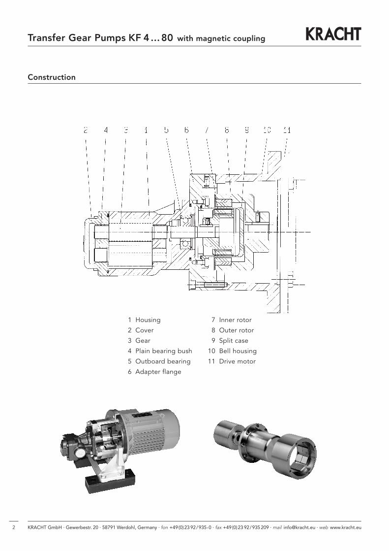
Construction
1 Housing
2 Cover
3 Gear
4 Plain bearing bush
5 Outboard bearing
6 Adapter flange
7 Inner rotor
8 Outer rotor
9 Split case
10 Bell housing
11 Drive motor
Transfer Gear Pumps KF 4 ... 80 with magnetic coupling
KRACHT GmbH · Gewerbestr. 20 · 58791 Werdohl, Germany · fon +49(0)23 92/935-0 · fax +49(0)23 92/935 209 · mail [email protected] · web www.kracht.eu 3
Transfer Gear Pumps KF 4 ... 80 with magnetic coupling
General Characteristics
Fixing type Flange type
Pipe connection KF4… 25 Pipe threadKF32… 80 Flange connection
Direction of rotation clockwise or anticlockwise
Fitting position Horizontal, vertical(shaft end facing downward/at the bottom)
Operation Characteristics
Nominal displacement Vg = 4 / 5 / 6 / 8 / 10 / 12 / 16 / 20 / 25 /32 / 40 / 50 / 63 / 80 cm3/r
Working pressure Inlet portpe min -- 0.4 bar, vacuum facility -- 0.92 barpe max 16 bar (SN1 / SS1 / NN1)pe max 25 bar (SN2 / SS2 / NN2)pe max 40 bar (SN3 / SS3 / NN3)
Standstillpe min -- 1 barpe max 16 bar (SN1 / SS1 / NN1)pe max 25 bar (SN2 / SS2 / NN2)pe max 40 bar (SN3 / SS3 / NN3)
Working pressure Outlet portpn max DU bearing: 25 bar
Iglidur bearing: 10 bar via pe
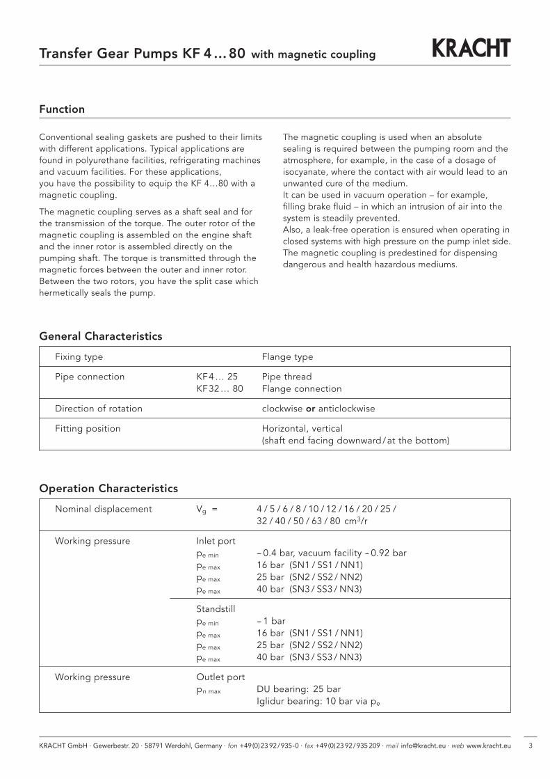
Function
Conventional sealing gaskets are pushed to their limitswith different applications. Typical applications arefound in polyurethane facilities, refrigerating machinesand vacuum facilities. For these applications, you have the possibility to equip the KF 4…80 with amagnetic coupling.
The magnetic coupling serves as a shaft seal and forthe transmission of the torque. The outer rotor of themagnetic coupling is assembled on the engine shaftand the inner rotor is assembled directly on the pumping shaft. The torque is transmitted through themagnetic forces between the outer and inner rotor.Between the two rotors, you have the split case whichhermetically seals the pump.
The magnetic coupling is used when an absolute sealing is required between the pumping room and theatmosphere, for example, in the case of a dosage ofisocyanate, where the contact with air would lead to anunwanted cure of the medium. It can be used in vacuum operation – for example, filling brake fluid – in which an intrusion of air into thesystem is steadily prevented.Also, a leak-free operation is ensured when operating inclosed systems with high pressure on the pump inlet side.The magnetic coupling is predestined for dispensingdangerous and health hazardous mediums.
KRACHT GmbH · Gewerbestr. 20 · 58791 Werdohl, Germany · fon +49(0)23 92/935-0 · fax +49(0)23 92/935 209 · mail [email protected] · web www.kracht.eu4
Operation Characteristics
Speed nmin = 200 1/minnmax = 3000 1/min
Viscosity νmin = 10 mm2/sνmax = 5000 mm2/s
Fluid temperature pump ϑm min = -- 10 °Cϑm max = 130 °C (EPDM)ϑm max = 100 °C (CR)ϑm max = 100 °C (HNBR)ϑm max = 130 °C (FKM), Magnet material NdFeBϑm max = 150 °C (FKM), Magnet material SmCoϑm max = 200 °C (FEP), Magnet material SmCo
Fluid temperature magnetic coupling ϑm max = 130 °C Magnet material NdFeBϑm max = 250 °C Magnet material Sm2Co17
Ambient temperature ϑu min = -- 20 °Cϑu max = 60 °C
Nominal torque magnetic coupling MSA 46/6 3 Nm MSB 75/10 20 Nm
MSA 60/8 7 Nm MSC 75/10 30 Nm
MSB 60/8 14 Nm MSB 110/16 50 Nm
MSA 75/10 10 Nm MSC 110/16 80 Nm
Materials pump Housingand cover EN-GJL-250 (GG 25)
EN-GJS-400-15 (GGG 40) on request
Gear 16 Mn Cr 5
Bearing bushes DU, optional Iglidur (sealing number 12, 16)
Seals EPDM, CR, HNBR, FKM, FEP
Materials magnetic coupling Inner rotor Hub made of stainless steel 1.4571Magnets made of SM2Co17Magnet covering made of stainless steel 1.4571
Split case Flange made of stainless steel 1.4571Pot made of stainless steel 1.4571From construction size 75, alternatively made of Hastelloyy
Outer rotor Hub made of 355J2G3 (St 52)Magnet made of Sm2Co17 oder NdFeB
Transfer Gear Pumps KF 4 ... 80 with magnetic coupling
KRACHT GmbH · Gewerbestr. 20 · 58791 Werdohl, Germany · fon +49(0)23 92/935-0 · fax +49(0)23 92/935 209 · mail [email protected] · web www.kracht.eu 5
Transfer Gear Pumps KF 4 ... 80 with magnetic coupling
Pump Coupling Permitted Permitted Motor Permitted Motor Permitted Motorsize torque power size power size power size
consumption consumption consumptionat 20 °C [kW] at [kW] at [kW] at
[Nm] n = 750 1/min n = 950 1/min n = 1450 1/min
MSA 46 3 – – 0.18 710.18 63
0.25 71
MSA 60 70.18 80 0.25 71 0.37 71
KF 4-250.25 80 0.37 80 0.55 80
MSB 60 140.37 90 0.55 80 0.75 80
0.55 90 0.75 90 1.10 90
MSB 75 240.75 100 1.10 90 1.50 90
1.10 100 1.50 100 2.20 100
MSB 75 240.75 100 1.10 90 1.50 90
1.10 100 1.50 100 2.20 100
MSC 75 401.50 112 2.20 112 3.00 100
KF 32-80 2.20 132 3.00 132 4.00 112
MSB 110 60 3.00 132 4.00 132 5.50 132
MSC 110 954.00 160 5.50 132 7.50 132
5.50 160 7.50 160 11.0 0 160
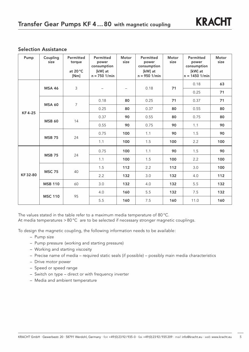
Selection Assistance
The values stated in the table refer to a maximum media temperature of 80 °C. At media temperatures > 80 °C are to be selected if necessary stronger magnetic couplings.
To design the magnetic coupling, the following information needs to be available:– Pump size– Pump pressure (working and starting pressure)– Working and starting viscosity– Precise name of media – required static seals (if possible) – possibly main media characteristics– Drive motor power– Speed or speed range– Switch on type – direct or with frequency inverter– Media and ambient temperature
KRACHT GmbH · Gewerbestr. 20 · 58791 Werdohl, Germany · fon +49(0)23 92/935-0 · fax +49(0)23 92/935 209 · mail [email protected] · web www.kracht.eu6
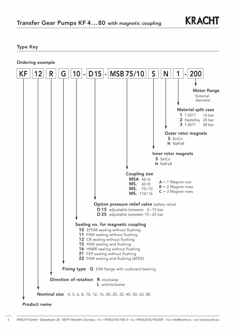
Type Key
Transfer Gear Pumps KF 4 ... 80 with magnetic coupling
Ordering example
KF 12 R G 10 - D15 - MSB 75/10 S N 1 - 200
Option pressure relief valve (safety valve)D 15 adjustable between 0 –15 barD 25 adjustable between 15 – 25 bar
Sealing no. for magnetic coupling10 EPDM sealing without flushing11 FKM sealing without flushing12 CR sealing without flushing15 FKM sealing and flushing16 HNBR sealing without flushing21 FEP sealing without flushing22 FKM sealing and flushing (ATEX)
Fixing type G DIN flange with outboard bearing
Direction of rotation R clockwiseL anticlockwise
Product name
Nominal size 4, 5, 6, 8, 10, 12, 16, 20, 25, 32, 40, 50, 63, 80
Inner rotor magnetsS SmCoN NdFeB
Outer rotor magnetsS SmCoN NdFeB
Material split case1 1.4571 16 bar2 Hastelloy 25 bar3 1.4571 40 bar
Motor flangeExternaldiameter
Coupling sizeMSA 46/6MS. 60/8MS. 75/10MS. 110/16
A = 1 Magnet rowB = 2 Magnet rowsC = 3 Magnet rows
KRACHT GmbH · Gewerbestr. 20 · 58791 Werdohl, Germany · fon +49(0)23 92/935-0 · fax +49(0)23 92/935 209 · mail [email protected] · web www.kracht.eu 7
Transfer Gear Pumps KF 4 ... 80 with magnetic coupling
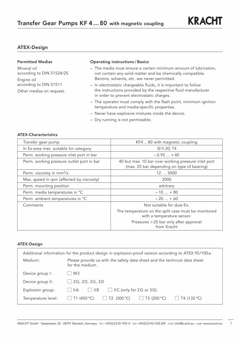
ATEX-Design
Permitted Medias
Mineral oil according to DIN 51524/25
Engine oil according to DIN 51511
Other medias on request.
Transfer gear pump KF4 ... 80 with magnetic coupling
In Ex-area max. suitable for category II 2G T4
Perm. working pressure inlet port in bar – 0.92 ... + 40
Perm. working pressure outlet port in bar 40 but max. 10 bar over working pressure inlet port(max. 25 bar depending on type of bearing)
Perm. viscosity in mm2/s 12 … 5000
Max. speed in rpm (affected by viscosity) 3000
Perm. mounting position arbitrary
Perm. media temperatures in °C – 10 ... + 80
Perm. ambient temperatures in °C – 20 ... + 60
Comments Not suitable for dust-Ex.The temperature on the split case must be monitored
with a temperature sensor.Pressures > 25 bar only after approval
from Kracht
Additional information for the product design in explosion-proof version according to ATEX 95/100a:
Medium: Please provide us with the safety data sheet and the technical data sheet for the medium.
Device group I : � M2
Device group II : � 2G, 2D, 3G, 3D
Explosion group: � IIA � IIB � IIC (only for 2G or 3G)
Temperature level: � T1 (450 °C) � T2 (300 °C) � T3 (200 °C) � T4 (135 °C)
Operating instructions / Basics
– The media must ensure a certain minimum amount of lubrication, not contain any solid matter and be chemically compatible. Benzins, solvents, etc. are never permitted.
– In electrostatic chargeable fluids, it is important to follow the instructions provided by the respective fluid manufacturer in order to prevent electrostatic charges.
– The operator must comply with the flash point, minimum ignitiontemperature and media-specific properties.
– Never have explosive mixtures inside the device.
– Dry running is not permissible.
ATEX-Characteristics
ATEX-Design
KRACHT GmbH · Gewerbestraße 20 · 58791 Werdohl, Germany · fon +49 (0) 23 92 / 935-0 · fax +49 (0) 23 92 / 935 209
mail [email protected] · web www.kracht.eu
KF4...80 m.Magnk./GB/03.09
Transfer PumpsTransfer pumps for lubricating oil supply equipment, low pressure filling and feed systems, dosing and mixing systems.
Mobile HydraulicsSingle and multistage high pressure gear pumps, hydraulic motors and valves for construction machinery, vehicle-mounted machines.
Flow MeasurementGear and turbine flow meters and electronics for volume and flow metering technology in hydraulics, processing and laquering technology.
Industrial Hydraulics /Test Bench ConstructionCetop directional control and proportional valves, hydraulic cylinders, pressure, quantity and stop valves for pipe and slab construction, hydraulic accessories for industrial hydraulics (mobile and stationary use).
Technology Test benches / Fluid Test benches.
Product Portfolio


