OPEN ACCESS Transformation optics for the full dielectric electromagnetic cloak and metal–dielectric planar hyperlens To cite this article: D P Gaillot et al 2008 New J. Phys. 10 115039 View the article online for updates and enhancements. You may also like A variable-impedance piezoelectric tactile sensor with tunable sensing performance for tissue hardness sensing in robotic tumor palpation Feng Ju, Yahui Yun, Zhao Zhang et al. - Characteristic wave velocities in spherical electromagnetic cloaks A D Yaghjian, S Maci and E Martini - Analysis of industrial performance in terms of achieving quality goals O V Anikeeva, A G Ivakhnenko and M L Storublev - This content was downloaded from IP address 58.153.240.63 on 08/02/2022 at 07:39
Transcript
OPEN ACCESS
Transformation optics for the full dielectricelectromagnetic cloak and metal–dielectric planarhyperlensTo cite this article: D P Gaillot et al 2008 New J. Phys. 10 115039
View the article online for updates and enhancements.
You may also likeA variable-impedance piezoelectric tactilesensor with tunable sensing performancefor tissue hardness sensing in robotictumor palpationFeng Ju, Yahui Yun, Zhao Zhang et al.
-
Characteristic wave velocities in sphericalelectromagnetic cloaksA D Yaghjian, S Maci and E Martini
-
Analysis of industrial performance in termsof achieving quality goalsO V Anikeeva, A G Ivakhnenko and M LStorublev
-
This content was downloaded from IP address 58.153.240.63 on 08/02/2022 at 07:39
T h e o p e n – a c c e s s j o u r n a l f o r p h y s i c s
New Journal of Physics
Transformation optics for the full dielectricelectromagnetic cloak and metal–dielectricplanar hyperlens
D P Gaillot, C Croenne, F Zhang and D Lippens1
Institut d’Electronique de Microélectronique et de Nanotechnologie,Université des Sciences et Technologies de Lille, UMR CNRS 8520,Avenue Poincaré, BP 60069, 59652 Villeneuve d’Ascq, FranceE-mail: [email protected]
New Journal of Physics 10 (2008) 115039 (15pp)Received 6 June 2008Published 27 November 2008Online at http://www.njp.org/doi:10.1088/1367-2630/10/11/115039
Abstract. Full dielectric electromagnetic cloaks are studied in this paper forconsidering the possibility of achieving effective permeability gradients bytaking advantage of a magnetic Mie resonance in high-κ ceramics. Extremeperformance sensitivity to the dispersion of the complex effective parameters,which could be problematic for practical realization, is pointed out. In asecond stage, we apply transformation optics for achieving magnification andhigh-resolution focusing in highly anisotropic metal–dielectric flat lenses.
Contents
1. Introduction 22. Basic principle of Mie magnetic resonance 33. High-κ ceramic electromagnetic cloak at terahertz frequencies 54. Transformation optics for a flat hyperlens 95. Conclusion 14Acknowledgments 15References 15
1 Author to whom any correspondence should be addressed.
Moulding the flow of light has already been the main goal of photonic crystal technology [1].Towards this goal, new degrees of freedom were afforded by the emergence of so-calledmetamaterial technology based on the structuring of artificial matter on a scale much shorterthan the operating wavelength. This permits one to open the effective parameter space, with notonly negative values of the effective permittivity and permeability but also the possibility ofconsidering zero-index media or having permittivity and permeability values that vary betweenzero and one. This latter case corresponds to a superluminal operating condition and henceallows the bending of light in certain regions of the geometrical space by keeping the sametime of flight with respect to the corresponding straightforward transmitted waves. The Fermatprinciple is hence satisfied.
Such a bending of light opens the way to electromagnetically isolating some regionsof space, which thus become undetectable by a point or distributed probing source. Anyscatterers such as a metal rod or sphere, depending on the dimensionality of the system,placed in these isolated space regions, become invisible or equivalently become transparentfor the probing waves. The activities in this research field, termed cloaking, are now mainlyfocused on the design, fabrication and experimental assessment of transparency cloaks. Thereferences [2]–[10] can be considered as seminal papers in this very recent field which revisitsnotably the invisibility concept.
So far, most of the experimental works that have been reported for achieving such a highdegree of transparency use the idea of space deformation by means of gradient index cloaks.In the microwave spectral region, the index gradients are mainly achieved by an engineeringof the effective permeability. Now, it is well known that metal loops, which can be comparedwith the so-called split-ring resonator (SRR) technology, yield negative values of the effectivepermeability (µeff) between the resonant and the plasma magnetic frequencies. Above themagnetic plasma frequency, the value of µeff can thus be between zero and one. In optics, theengineering of the effective permittivity was found to be preferable and some modelling resultshave been published on ellipsoidal-shaped radial metal inclusions [6] or non-uniform sectionbars, in order to induce permittivity gradients. With respect to the first principle experimentaldemonstrations, a microwave cloak was recently realized [5]. It was based on a reduced setof equations (see [7]), which relax the technological difficulty since an ideal cloak approachrequires the engineering simultaneously of the permittivity and permeability parameters. Inpractice, the cloak was made of concentric dielectric cylindrical-shaped boards with printededge-coupled C-shaped SRRs.
However, the extension of such studies to higher frequencies, notably in the terahertzspectral region by shrinking the SRR dimensions, appears problematic. The reason for this isthe complexity of the realization of such a prototype whose dimensions have to be in the micronscale. In this paper, we show how such a problem can be alleviated by taking advantage of theground magnetic Mie resonance in high-κ dielectric rods. Recently, we showed that the basicprinciple is similar to that used in SRR, namely an engineering of the magnetic response by sizeeffects [11]. Here, it is shown that the operating frequency can be extended by more than twoorders of magnitude with similar prospects in terms of performance. In a more general manner,we also address the problem of the size of the object that we would like to cloak.
On the other hand, transformation optics can be applied to other applications includinghigh-resolution focusing. Among the various possibilities reported in the literature, special
New Journal of Physics 10 (2008) 115039 (http://www.njp.org/)
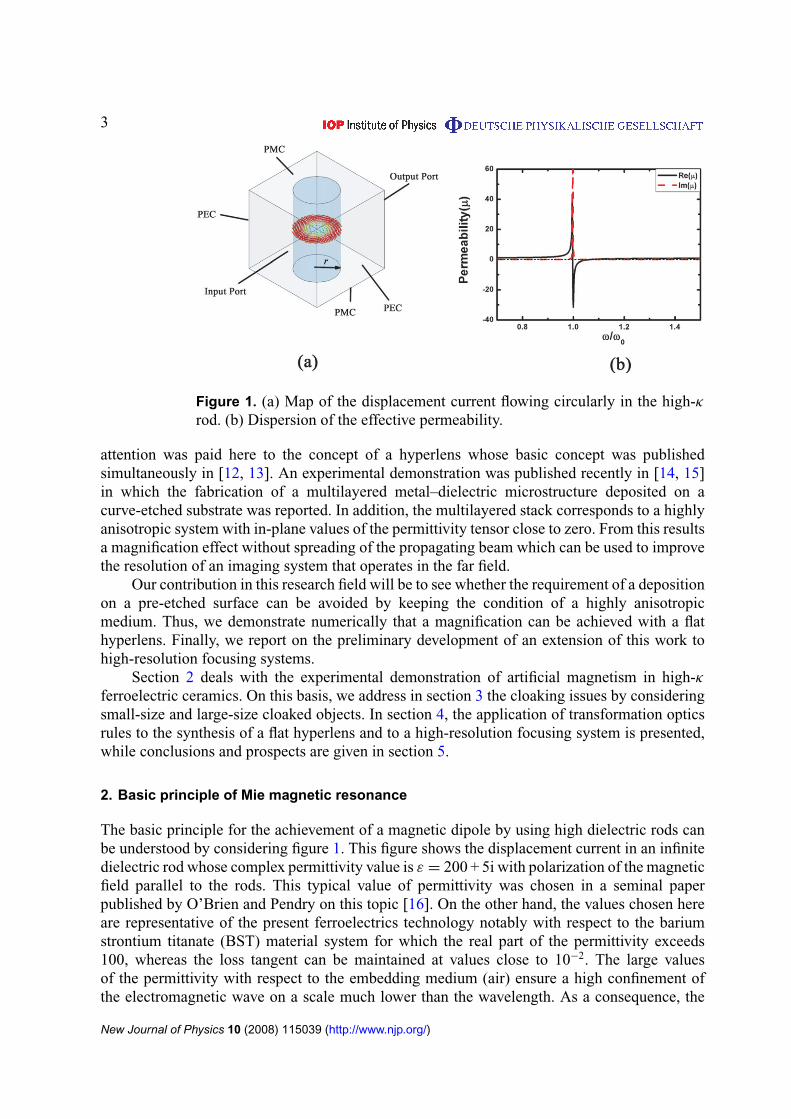
Figure 1. (a) Map of the displacement current flowing circularly in the high-κrod. (b) Dispersion of the effective permeability.
attention was paid here to the concept of a hyperlens whose basic concept was publishedsimultaneously in [12, 13]. An experimental demonstration was published recently in [14, 15]in which the fabrication of a multilayered metal–dielectric microstructure deposited on acurve-etched substrate was reported. In addition, the multilayered stack corresponds to a highlyanisotropic system with in-plane values of the permittivity tensor close to zero. From this resultsa magnification effect without spreading of the propagating beam which can be used to improvethe resolution of an imaging system that operates in the far field.
Our contribution in this research field will be to see whether the requirement of a depositionon a pre-etched surface can be avoided by keeping the condition of a highly anisotropicmedium. Thus, we demonstrate numerically that a magnification can be achieved with a flathyperlens. Finally, we report on the preliminary development of an extension of this work tohigh-resolution focusing systems.
Section 2 deals with the experimental demonstration of artificial magnetism in high-κferroelectric ceramics. On this basis, we address in section 3 the cloaking issues by consideringsmall-size and large-size cloaked objects. In section 4, the application of transformation opticsrules to the synthesis of a flat hyperlens and to a high-resolution focusing system is presented,while conclusions and prospects are given in section 5.
2. Basic principle of Mie magnetic resonance
The basic principle for the achievement of a magnetic dipole by using high dielectric rods canbe understood by considering figure 1. This figure shows the displacement current in an infinitedielectric rod whose complex permittivity value is ε = 200 + 5i with polarization of the magneticfield parallel to the rods. This typical value of permittivity was chosen in a seminal paperpublished by O’Brien and Pendry on this topic [16]. On the other hand, the values chosen hereare representative of the present ferroelectrics technology notably with respect to the bariumstrontium titanate (BST) material system for which the real part of the permittivity exceeds100, whereas the loss tangent can be maintained at values close to 10−2. The large valuesof the permittivity with respect to the embedding medium (air) ensure a high confinement ofthe electromagnetic wave on a scale much lower than the wavelength. As a consequence, the
New Journal of Physics 10 (2008) 115039 (http://www.njp.org/)
Figure 2. (a) Photograph of high-κ ceramic BST cubes. Source: courtesy of theUniversity of Tsinghua [15]. (b) Illustration of the Mie magnetic resonance.
metamaterial condition can be met despite the fact that we are considering a full dielectricroute. The induced circular displacement current induces a magnetic response which can be outof phase (negative value of the permeability) above the resonant frequency. When the rods areorganized in arrays, which is the case with the simulation with appropriate boundary conditionsin order to mimic an infinite medium, the negative permeability is lost above the magneticplasma frequency.
These considerations can be quantitatively assessed by means of the retrieval of theeffective permeability, which is plotted in figure 1(b) as a function of the normalized angularfrequency ω/ωo. The frequency dependence of the effective permeability follows a Lorentz-type dispersion characteristic with negative values of the permeability between the resonantfrequency and the magnetic plasma frequency. Both frequencies can be engineered as for SRRs.In fact, we learnt from the analysis outlined above that the basic principle behind the originof an artificial magnetic moment is similar with respect to SRR physics. Therefore, the sameengineering rules can be applied to tailor the resonant frequency and the magnetic plasmafrequency, which depend on the filling factor. As a consequence, two degrees of freedom can bedefined with the radius of the rods and the array period. As demonstrated in [11] for cloaking,the values of µeff above the plasma frequency will be of interest with a radial variation of the rodradius, whereas the period is kept constant. Before considering in further detail the advantagesand also the drawbacks associated with such a full dielectric cloak, we report hereafter someexperimental verification that a bulk ferroelectric technology is suitable for inducing an artificialmagnetic response. This experimental demonstration will be carried out at microwave frequencyfor the sake of simplicity. However, the underlying principles are valid over a large portion ofthe electromagnetic spectrum provided that a high value of permittivity can be preserved.
While a cylinder-shaped rod is ideal for achieving circular currents, their fabricationin practice is troublesome at ultra-small dimensions. Recently, the University of Tsinghuasucceeded in fabricating BST ceramic cubes, which were subsequently characterized over awide temperature range around the Curie temperature [17].
Further details of the fabrication techniques and the temperature dependence of the materialproperties can be found in [17] . In the present paper, special attention will be paid to theexperimental derivation of the dispersion characteristics at room temperature. To achieve thisaim, BST ceramic cubes were organized into a square lattice embedded in a Teflon film as shownin the photograph in figure 2. Each side of the cube is 0.9 mm long for a permittivity value as
New Journal of Physics 10 (2008) 115039 (http://www.njp.org/)
Figure 3. Retrieval of the complex impedance (a), propagation constant(b), and the corresponding effective magnetic permeability (c) and electricpermittivity (d).
high as 850. Under this condition, it can be shown that the resonant frequency lies in the X-band (8–12 GHz). The BST unit cell size fulfils the metamaterial condition as can be verifiedfrom figure 2(a). The dominant mode in the rectangular hollow waveguide is a TE10 modewith half a wavelength over the aperture of the flange. Figure 2(b) shows the variation versusfrequency of the magnitude of the scattering parameter S21,which was measured by vectorialnetwork analysis and calculated by means of a full wave analysis (the commercial softwareHigh Frequency Simulator from Ansoft). As expected, at the resonant frequency here of about9 GHz, the frequency dependence S21 shows a dip in the transmission, showing that the one-celllayer can be compared with a single negative medium.
Further information about the dispersion of the effective parameters can be achieved bymeans of retrieval techniques. Figure 3 shows the results extracted by means of a Fresnelinversion technique. Similar results are obtained by using a field summation technique [18]which was used in our previous publication on cloaking. It can be seen that above the resonantfrequency the one-cell layer exhibits a negative permeability, whereas the effective permittivityis almost constant with an effective value close to 1.7.
3. High-κ ceramic electromagnetic cloak at terahertz frequencies
As outlined in the introduction, the main advantage of a BST cloak is the simplicity offabrication in the terahertz range. Also, one can imagine extending the operating frequency up
New Journal of Physics 10 (2008) 115039 (http://www.njp.org/)
Figure 4. Steady-state Ez pattern calculated at 0.58 THz for a copper rodwithout (a) and with (d) a 3D microstructured cloak shown in (b). The planeof observation is located at mid-distance between the bottom and top facesof the simulation domain. The wavefronts are well reconstructed behind thecloak without noticeable backscattering. The metallic particle placed at thecentre of the device is nearly ‘invisible’ to a detector located at the output port.(c) Magnified view of the field pattern within the cloak. For clarity, the amplitudewithin the cloak was magnified.
to the mid- and near-infrared spectral region. However, the main difficulty in achieving this goalstems from the fact that the BST cube exhibits Debye relaxation effects. As a consequence,it becomes more and more difficult to preserve high permittivity values and to fulfil themetamaterial condition, resulting in a high confinement in a sub-wavelength scale.
Let us now consider how to take advantage of the artificial magnetism pointed out abovefor cloaking. Figure 4 summarizes the main features of a 3D cloak with the rod arrangement,and the mapping of the E-field magnitude for an infinite conductivity metal cylinder withand without the cloak. The calculations were here performed by describing all the details ofthe microstructure and not by considering a multilayered homogeneous structure. In order toillustrate these ab-initio calculations, a magnified view of the cloak region (figure 4(c)) is alsodisplayed showing the localization of the electromagnetic fields on a sub-wavelength. Thesecalculations were performed with a permittivity of the rods equal to ε = 200 + 5i and for anoperating frequency of about 0.5 THz. Further details of the reduced equations and the variationin the geometry of high-κ rods can be found in [11].
Mapping of the EM fields is the first stage in the assessment of an invisibility cloak.However, the calculation of the radar cross section (RCS), which is the cross sectional areaof a conductive cylinder that would reflect as much energy as the object in question, can bringfurther quantitative information about the sensitivity of the performance to the index gradients
New Journal of Physics 10 (2008) 115039 (http://www.njp.org/)
Figure 5. Total scattering cross section normalized to the scattering cross sectionof a bare metallic cylinder as a function of frequency for the bare metal cylinder(red), the reduced cloak (blue) and the lossless (green) and lossy (black) BSTcloaks.
and also the cloaking bandwidth. In the following, we will apply this approach to the case ofsmall-size and large-scale cloaks with respect to the wavelength of the incident wave. For thissystematic study, we used a homogeneous multilayered description for saving computationaltime [7]. In other words, we break the continuous cloaking material into shells along the radialdirection. For each shell, the effective parameters are those which can be computed by thefield summation technique [18]. This technique, whose results have been compared recentlywith the Fresnel inversion procedure, is comparable with the averaging technique of Smith andPendry [19]. In the first stage, it can be verified that the performances of a microstructured and amulti-shell cloak are similar provided that the pitch determined by the number of discrete layersis small with respect to the wavelength. The main difference appears qualitatively on the fieldmaps, which show finer features in the space variations for a microstructured cloak. Let us firstconsider a small-size cloak in the sense that the scatterer placed inside the cloak is of the orderof the incident wavelength.
First we calculated the total RCS of the cylinder-shaped perfect electric conductor andthen the RCS of a BST cloak and a reduced cloak. The latter is a single frequency cloakwhose effective parameters can be found in [7]. The scattered fields are calculated using theCOMSOL Multiphysics finite-element solver. By integrating the scattered field components inall directions, the RCS figure of merit can be deduced and the results are presented in figure 5.With respect to the RCS of 100% for a metal rod, it can be seen that introducing a non-dispersivecloak reduces the RCS to 30%. This reduction is substantial but is still far from the invisibilitycriterion of an ideal cloak. However, for a BST cloak, namely when we introduce dispersiveeffective parameters, this partial transparency exhibits a narrow band, which was estimated hereto be of the order of 10%. The fact that the frequency dependence of the effective permeabilityexhibits a Lorentz-type behaviour could explain such a narrow band, while a non-resonant
New Journal of Physics 10 (2008) 115039 (http://www.njp.org/)
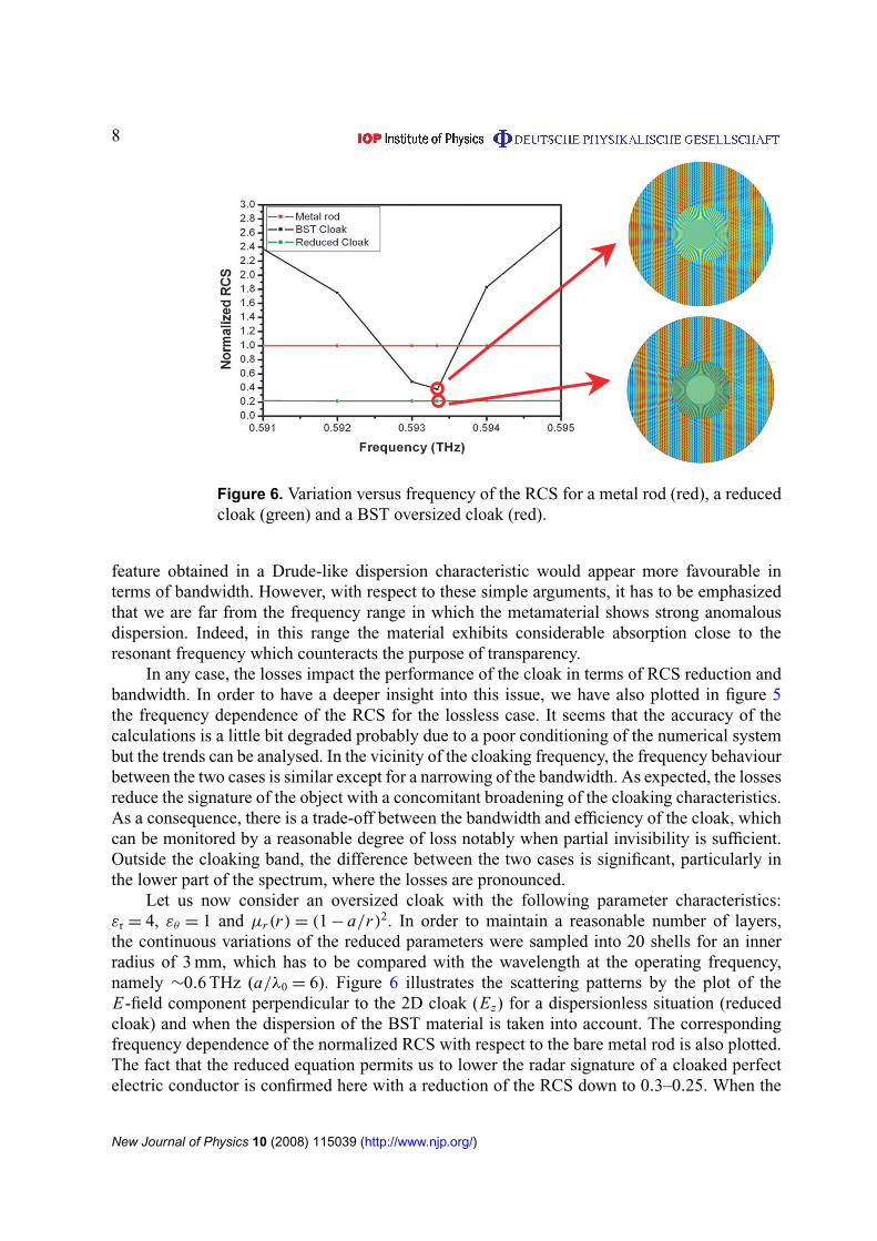
Figure 6. Variation versus frequency of the RCS for a metal rod (red), a reducedcloak (green) and a BST oversized cloak (red).
feature obtained in a Drude-like dispersion characteristic would appear more favourable interms of bandwidth. However, with respect to these simple arguments, it has to be emphasizedthat we are far from the frequency range in which the metamaterial shows strong anomalousdispersion. Indeed, in this range the material exhibits considerable absorption close to theresonant frequency which counteracts the purpose of transparency.
In any case, the losses impact the performance of the cloak in terms of RCS reduction andbandwidth. In order to have a deeper insight into this issue, we have also plotted in figure 5the frequency dependence of the RCS for the lossless case. It seems that the accuracy of thecalculations is a little bit degraded probably due to a poor conditioning of the numerical systembut the trends can be analysed. In the vicinity of the cloaking frequency, the frequency behaviourbetween the two cases is similar except for a narrowing of the bandwidth. As expected, the lossesreduce the signature of the object with a concomitant broadening of the cloaking characteristics.As a consequence, there is a trade-off between the bandwidth and efficiency of the cloak, whichcan be monitored by a reasonable degree of loss notably when partial invisibility is sufficient.Outside the cloaking band, the difference between the two cases is significant, particularly inthe lower part of the spectrum, where the losses are pronounced.
Let us now consider an oversized cloak with the following parameter characteristics:εr = 4, εθ = 1 and µr(r) = (1 − a/r)2. In order to maintain a reasonable number of layers,the continuous variations of the reduced parameters were sampled into 20 shells for an innerradius of 3 mm, which has to be compared with the wavelength at the operating frequency,namely ∼0.6 THz (a/λ0 = 6). Figure 6 illustrates the scattering patterns by the plot of theE-field component perpendicular to the 2D cloak (Ez) for a dispersionless situation (reducedcloak) and when the dispersion of the BST material is taken into account. The correspondingfrequency dependence of the normalized RCS with respect to the bare metal rod is also plotted.The fact that the reduced equation permits us to lower the radar signature of a cloaked perfectelectric conductor is confirmed here with a reduction of the RCS down to 0.3–0.25. When the
New Journal of Physics 10 (2008) 115039 (http://www.njp.org/)
dispersion of the parameter is introduced in the simulation of this large cloak, it can be seen thatthe cloaking bandwidth is very narrow with a value close to 1%. Therefore, very close to thevicinity of partial transparency frequency the efficiency of the cloak is rapidly degraded. Thisvery high sensitivity of the bandwidth to the size of the object located in the isolated region ofspace was confirmed by systematic simulations. It is not a specificity of a BST cloak providedthat the dispersion characteristics, which are primarily responsible for the narrowing of the band,are comparable.
4. Transformation optics for a flat hyperlens
The transformation procedure used to design a cloaking device is quite general [3]. In thissection, we will use this technique to magnify near-field patterns. Such a function is performedby a class of devices termed hyperlenses [12, 13]. The main idea is to channel and magnify anynear-field pattern in order to bring its fine details, originally carried by evanescent waves only,over the Abbe limit. Consequently, at the output of the hyperlens, those details are convertedinto propagating waves, which can then be probed in the far field by a conventional imagingsystem.
The already existing hyperlens devices are based on a channelling effect, which can beobserved in highly anisotropic metamaterials when their transverse permittivity (for transversemagnetic (TM) polarization) is positive and very close to zero. Such effective parameters canbe obtained with nanostructures that alternate metallic and dielectric layers. The magnificationeffect is then obtained by means of a cylindrical conformation of the layers. In other words,this hyperlens maps the near-field patterns of a small inner cylinder onto a large outer one. Themagnification coefficient is simply given by the ratio of the radii. One of the drawbacks of sucha structure is that both interfaces are cylinders and, therefore, introduce an important limitationin the lateral extent of the input patterns. In the following, starting from the flat channellingdevice, we will add the magnification effect by means of transformation optics while keepingboth interfaces flat. The main difference between the flat lens proposed in the present paperand that of the work described in [8] stems from the input boundary, which is a flat surfacein our case, whereas it is a cylinder in [8]. The flat surface permits one to greatly simplify theinterfacing of the lens with the object to be imaged.
Let us consider a flat channelling device in the xy-plane; z is the direction of the magneticfield (TM polarization), whereas y is the main propagation direction. Consequently, we haveto choose a very low value for εxx . In the following, we will use the lossless parameters(εxx , εyy , µzz) = (0.001, 2.5, 1). The device is positioned between y = a and y = b. Themagnification factor is t . The coordinate transformation used in the procedure is as follows:
x ′=
[(y − a
b − a
)(t − 1) + 1
]x,
y′= y,
z′= z.
(1)
This transformation, similar to equations (17)–(19) in [9], is linear with respect to x and y.On the input interface (y = a), we have an identity between the original and the transformedcoordinates. On the output interface (y = b), we ‘stretch’ the coordinates along the x-directionby a factor of t (x ′
= t x). It should be noted that such a transformation introduces an
New Journal of Physics 10 (2008) 115039 (http://www.njp.org/)
Figure 7. Full set of targeted effective parameters inside the flat hyperlens. Here,a = 1 mm, b = 5 mm and t = 5 have been taken as an example. The values of εxx
and εyy at the corners are off-scale.
‘optical axis’ since the translation along x is proportional to the distance to x = 0 at the input.However, at this point, it is not necessary to limit the device along the x-direction.
By following the procedure presented in [4] for this linear transformation, we obtain thelocal expressions for both the 2 × 2 permittivity tensor ε and the out-of-plane permeability (inour 2D TM case) of the device equivalent to the transformed space. These expressions onlydepend on the position, the geometrical parameters (a, b, t) and the original material parameters(εxx , εyy , µzz). They are plotted in figure 7 for a = 1 mm, b = 5 mm and t = 5, as an example.
The next step is to find out whether we can avoid the off-diagonal term εxy in thepermittivity tensor, which would be the most difficult to implement. This can be done by a properlocal rotation R(x, y) of angle θ(x, y) of the global Cartesian coordinate system (x, y, z). Wesolve: (
εi i 00 ε j j
)= R ε R−1
= R
(ε11 ε12
ε21 ε22
)R−1. (2)
The full expression for the local rotation is
θ =1
2tan−1
(2εyy(b − a)2(t − 1)x · f (y)
εxx f (y)4 + εyy(b − a)2((t − 1)2x2 − f (y)2)
)with f (y) = (b − at) + (t − 1)y. (3)
The θ(x, y), εi i(x, y) and ε j j(x, y)functions are plotted in figure 8 for the same values of(a, b, t) as before. The permeability distribution is unchanged. On the θ distribution, theexistence of a central ‘optical axis’ can be clearly seen. εi i , ε j j and µzz show significant gradientsover the surface of the lens. However, εi i and ε j j are of the same order of magnitude as εxx
(positive and close to 0) and εyy (greater than 1), respectively. Similarly, µzz is comparable with1. It should be noted that ε j j diverges for large values of x , particularly when y → a, whichlimits the lateral extent of the input pattern.
We introduced these local parameters as material parameters for a slab into a frequency-domain 2D finite element method solver (namely the commercial software COMSOL).
New Journal of Physics 10 (2008) 115039 (http://www.njp.org/)
Figure 8. (a) Spatial distribution of the rotation angle of the local coordinatesystem. The red arrows show the direction of the local j vector, for a discrete setof points. However, the angle is defined at every point inside the homogeneousslab. (b)–(d) Full set of effective parameters inside the flat hyperlens in the localrotated coordinate system (i, j, z).
The input near-field pattern is simply two very narrow (λ0/60) sources of magnetic field centredat + and −λ0/20 and positioned directly at the bottom interface of the lens. The rest of thebottom boundary is a perfect magnetic conductor. Above the lens is placed an air layer. The topand side boundaries are perfectly matched layers. The wavelength in air was chosen to be 7.5times larger than the thickness of the lens.
Figure 9 shows the resulting magnetic field map (a) and the plot of the same field on theinput and output boundaries of the lens (b). The distance between the two peaks is multipliedby t (5 here) thanks to the lens. It should be noted that a significant spreading of the peaks canalso be observed.
This set of parameters could be implemented by means of individual particles withcontrolled values of permittivity along two orthogonal directions and a controlled value ofpermeability along the third. Moreover, each one of them would have to be individuallyoriented. The structures presented in the first sections of this paper suggest that the realizationof such particles is not completely unrealistic. However, the actual importance of the calculatedconstraints should be checked.
Since we have noted the order of magnitude of the calculated perfect parameters, wecan check the effect of dropping all gradients on the local effective parameters in the rotatedcoordinate system. In other words, we define εi i = 0.001, ε j j = 2.5 and µzz = 1 at every pointinside the device, with the same θ(x, y) function as before.
Figures 9(c) and (d) show the same map and plot of the magnetic field as before but withthose simplified material parameters. The magnification effect is still present and the distance
New Journal of Physics 10 (2008) 115039 (http://www.njp.org/)
Figure 9. (a) Simulated magnetic field map inside the flat hyperlens followingequation (3) and in the air above for an input pattern of two sub-wavelengthsources. (b) Corresponding field plot for both interfaces of the lens. (c) and (d)Same field map and plot for the lens with simplified parameters (constants εi i
and ε j j ).
between the peaks is unchanged. This means that when a channelling slab is used, the properorientation of the anisotropy dominates over its specific values in the transformation procedure.
Additionally, it is possible to explore other θ(x, y) distributions that could performdifferent functions. Equation (4) (the variables a and b have the same meaning as before and allci are constants), for example, allows point-like sources at the input to be transformed into verylarge line sources at the output (figures 10(a) and (b)). Such a function could be useful in thefield of antennas. Equation (5) leads to a concentration of the field along the transverse direction(figure 11), which could be interesting in detection systems to focus energy onto a probe.
θ(x, y) = sign(x)
[tan−1
(−c1(|x | + c2)
b − a
b − y
)], (4)
θ(x, y) = tan−1
(c3
x(−y2 + (a + b)y − ab
)(a − b)2
). (5)
In summary, in order to perform a given operation on the field patterns, one can use either aθ(x, y) function given by a full transformation procedure or simply search for a suitable function
New Journal of Physics 10 (2008) 115039 (http://www.njp.org/)
Figure 10. (a) Orientation of vector j for the local rotation given by equation (4)(red arrows). The black curves are the limits of the layers normal to j that can beused to implement the required anisotropy. (b) The magnetic field inside the lensfor the homogeneous case (b) and the microstructured one (c), using the layerconfiguration of (a).
directly. The main point to be considered when using the second method is that the propagationdirection inside the lens is dominated by the local j vector. It should be noted that this can leadus back to the cylindrical hyperlens already mentioned: we just have to choose two cylindricalinterfaces and then a cylindrical θ(x, y) function is the most straightforward choice to map thefield from the inner to the outer interface [14, 15].
At this point, we have only used homogeneous simulations to check the validity of ourexpressions. However, it is possible to implement a microstructure into our FEM software. Inother words, we will replace the locally rotated effective parameters by a metamaterial structurethat only uses simple materials arranged into a suitable geometry. Following the previous workson hyperlenses, we can try with a stack of layers of two different materials (of permittivitiesε1 and ε2). When the layers are of equal thickness, very thin with respect to the wavelengthand most importantly normal to the j -direction, the effective parameters are directly given byequation (6). For example, in order to obtain εi i = 0.001 and ε j j = 2.5, we will use layers withpermittivities of ε1 = 0.001 − 0.05i and ε2 = 0.001 + 0.05i (the gain comes from the constraintof zero loss for the effective parameters).
εi i=
ε1 + ε2
2,
ε j j=
2ε1ε2
ε1 + ε2.
(6)
All the possible layer boundaries form a family of curves that can be found by solvingthe equation of orthogonality with j (x, y). Among these curves, we can choose any subsetthat corresponds to reasonable thicknesses with respect to the homogenization conditions.Figure 10(a) shows such a set of curves for the lens that follows equation (4). It can be seenthat the condition of equal thickness is not globally respected. However, since the gradient on
New Journal of Physics 10 (2008) 115039 (http://www.njp.org/)
Figure 11. (a) Orientation of vector j for the local rotation given by equation (5)(red arrows). Magnetic field inside the lens and in the air above (c) for thehomogeneous case. (b) Corresponding field plot on both interfaces of the lens,showing concentration of the field along the transverse direction. Unlike theprevious cases, this simulation includes losses (loss tangent of 21 and 0.03 forεi i and ε j j , respectively).
the thickness is small, we can reasonably consider that we have locally neighbouring layers ofapproximately equal thickness. The relevance of this assumption is confirmed by the simulationresult for the microstructured slab presented in figure 10(c).
Finally, it should be noted that most of the calculations were performed for losslesscases. The introduction of losses can significantly deteriorate the performance of hyperlenses.However, the deterioration is strongly dependent on the length of the path inside the device. Forinstance, the deterioration is very strong when we follow equation (4) (figure 10 shows a losslesscase only), whereas it is reasonable for the field concentrator with equation (5) (figure 11 showsa lossy case).
5. Conclusion
A full dielectric approach taking advantage of the recent advances in ferroelectric technologyseems suitable for fabricating a partial transparency cloak at terahertz frequency. The underlyingphysics principles that permit one to tailor the effective permeability values are similar to thoseused for an SRR cloak operating at microwave frequency. As a consequence, a high-κ cloak alsosuffers from the same frequency limitations by showing comparable Lorentz-type dispersioncharacteristics. However, the technological challenges are dramatically relaxed when the upperpart of the electromagnetic spectrum is targeted. The concept of magnetic Mie resonance
New Journal of Physics 10 (2008) 115039 (http://www.njp.org/)
resulting from the light confinement is quite general and could be extended in principle tooptics where metal nanowire arrays were proposed to satisfy the localization [20]. Beyondthe search for invisibility, which is an ultimate goal in the control of light, other applicationscould be addressed through transformation optics such as lenses. In particular, we demonstratedthat hyperlens or high focusing devices can be designed by this procedure having in mind thetechnological constraints and notably flat interfaces. Such a condition is a requirement in planardeposition techniques such as those used in full semiconductor technology [21].
Acknowledgments
This work was carried out in the framework of the French DGA (Délégation Généraleà l’Armement) and of the Ariadna programme of the European Space Agency (ESA). We thankJose Montelio from ESA and Wounjhang Park from the University of Boulder (Boulder, CO,USA) for fruitful discussions. We also thank Ji Zhou from the University of Tsinghua for thesupply of the BST samples.
References
[1] Joannopoulos J D, Meade R D and Winn J N 1995 Photonic Crystals: Molding the Flow of Light(Princeton, NJ: Princeton University Press)
[2] Leonhardt U 2006 Science 312 1777–80[3] Pendry J B, Shurig D and Smith D R 2006 Science 312 1780–82[4] Schurig D, Pendry J B and Smith D R 2006 Opt. Express 14 9794–804[5] Schurig D, Mock J J, Justice B J, Cummer S A, Pendry J B, Starr A F and Smith D R 2006 Science
314 977–80[6] Cai W, Chettiar U K, Kildishev A V and Shalaev V M 2007 Nat. Photonics 1 224–7[7] Cummer S A, Popa B I, Schurig D, Smith D R and Pendry J 2006 Phys. Rev. E 74 36621[8] Kildishev A V and Shalaev V M 2008 Opt. Lett. 33 43[9] Rahm M, Roberts D A, Pendry J B and Smith D R 2008 Opt. Express 16 11555
[10] Rahm M, Shurig D, Roberts D A, Cummer S A, Smith D R and Prendy J B 2008 Photon. Nanostruct. Fundam.Appl. 6 87
[11] Gaillot D P, Croënne C and Lippens D 2008 Opt. Express 16 3986[12] Salandrino A and Engheta N 2006 Phys. Rev. B 74 075103[13] Jacob Z, Alekseyev L V and Narimanov E 2006 Opt. Express 14 8247[14] Liu Z, Lee H, Xiong Y, Sun C and Zhang X 2007 Science 315 686[15] Lee H, Liu Z, Xiong Y, Sun C and Zhang X 2007 Opt. Express 15 15886[16] O’Brien S and Pendry J B 2002 J. Phys.: Condens. Matter 14 4035[17] Zhao Q, Du B, Kang L, Zhao H, Xie Q, Li B, Zhang X, Zhou J, Li L and Meng Y 2008 Appl. Phys. Lett.
92 051106[18] Acher O, Lerat J-M and Malléjac N 2007 Opt. Express 15 1096–106[19] Smith D R and Pendry J B 2006 J. Opt. Soc. Am. B 23 391–403[20] Wu Qi and Park W 2008 Appl. Phys. Lett. 92 153114[21] Hoffman J, Alekseyev L, Howard S S, Franz K J, Wasserman D, Podolskiy V, Narimanov E E, Sivco D L and
Gmachl C 2007 Nat. Lett. 6 946–50
New Journal of Physics 10 (2008) 115039 (http://www.njp.org/)


![Radiation Characteristics Enhancement of Dielectric Resonator … · 2019. 10. 25. · lens [15]. Large aperture aspheric dielectric lens is proposed for quasi-optics design [16].](https://static.documents.pub/doc/80x56/61057b36df1ef87129263930/radiation-characteristics-enhancement-of-dielectric-resonator-2019-10-25-lens.jpg)
