1 http://eedofdit.weebly.com, © Nafees Ahmed
Transformer Design (© Dr. R. C. Goel & Nafees Ahmed )
By
Nafees Ahmed Asstt. Prof. Department of Electrical Engineering
DIT, University, Dehradun, Uttarakhand
References:
1. Notes by Dr. R. C. Goel
2. Electrical Machine Design by A.K. Sawhney
3. Principles of Electrical Machine Design by R.K Agarwal
4. VTU e-Learning
5. www.google.com
6. www.wikipedia.org
2 http://eedofdit.weebly.com, © Nafees Ahmed
OUTPUT EQUATION: - It gives the relationship between electrical rating and physical dimensions
of the machines.
Let
V1 = Primary voltage say LV
V2 = Secondary voltage say HV
I1 = Primary current
I2 = Secondary current
N1= Primary no of turns
N2= Secondary no of turns
a1 = Sectional area of LV conductors (m2)
=
1I
a2 = Sectional area of HV conductors (m2)
=
2I
= Permissible current density (A/m2)
Q = Rating in KVA
We place first half of LV on one limb and rest half of LV on other limb to reduce leakage flux.
So arrangement is LV insulation then half LV turns then HV insulation and then half HV turns.
(1) For 1-phase core type transformer
Rating is given by
Q = 3
11 10IV KVA
= 3
11 1044.4 INf m KVA 11 44.4 NfV m
= 311 1044.4 INBAf mi KVA -----------(1) )( mim BA
Where
f = frequency
m = Maximum flux in the core
iA = Sectional area of core
mB = Maximum flux density in the core
Window Space Factor
)( w
wAAreaWindow
WindowinWindingsofAreaSectionCuActualK
wA
NaNa 2211
)/&/()/()/(
22112211
IaIa
A
NINI
w
wA
NINI
2211
So
L
V
L
V
L
V
L
V
H
V
H
V
H
V
H
V
1-phase core type transformer with
concentric windings
Window
)(2
221111 NINIrTransformeIdealFor
A
NI
w
3 http://eedofdit.weebly.com, © Nafees Ahmed
)2(2
11
ww AK
IN
Put the value of N1I1 form equation (2) to equation (1)
KVAAK
BAfQ wwmi
3102
44.4
)3(1022.2 3 KVAAKBAfQ wwmi
(2) For 1- phase shell type transformer
Window Space Factor
Kw
wA
NaNa 2211
)/&/()/()/(
22112211
IaIa
A
NINI
w
wA
NINI
2211
)(2
221111 NINIrTransformeIdealFor
A
NI
w
So
)4(2
11 wwAKIN
Put the value of N1I1 form equation (4) to equation (1)
KVAAK
BAfQ wwmi
3102
44.4
)5(1022.2 3 KVAAKBAfQ wwmi
Note it is same as for 1-phase core type transformer i.e. equ (3)
(3) For 3-phase core type transformer
Rating is given by
Q = 3
11 103 IV KVA
= 3
11 1044.43 INf m KVA 11 44.4 NfV m
= 3
11 1044.43 INBfA mi KVA -----------(6) )( mim BA
Window Space Factor
L
V
L
V
H
V
H
V
L
V
L
V
H
V
H
V
3-phase core type transformer with
concentric windings
L
V
L
V
H
V
H
V
Window
1-phase shell type transformer with
sandwich windings
LV
HV
LV
HV
LV
LV
HV
LV
HV
LV
Window
4 http://eedofdit.weebly.com, © Nafees Ahmed
)( w
wAAreaWindow
WindowinWindingsofAreaSectionCuActualK
wA
NaNa )(2 2211
)/&/(
)/()/(22211
2211
IaIaA
NINI
w
wA
NINI
)(2 2211
)(22
221111 NINIrTransformeIdealFor
A
NI
w
So
)7(4
11 wwAKIN
Put the value of N1I1 form equation (7) to equation (6)
KVAAK
BAfQ wwmi
3104
44.43
)8(1033.3 3 KVAAKBAfQ wwmi
(3) For 3- phase shell type transformer
Window Space Factor
Kw
wA
NaNa 2211
)/&/()/()/(
22112211
IaIa
A
NINI
w
wA
NINI
2211
)(2
221111 NINIrTransformeIdealFor
A
NI
w
So
)9(2
11 wwAKIN
Put the value of N1I1 form equation (9) to equation (6)
KVAAK
BAfQ wwmi
3102
44.43
)10(1066.6 3 KVAAKBAfQ wwmi
3-phase shell type transformer with
sandwich windings
Window
5 http://eedofdit.weebly.com, © Nafees Ahmed
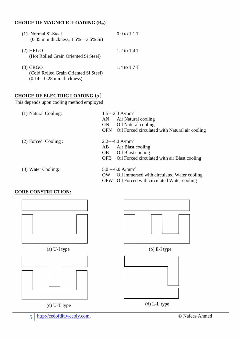
CHOICE OF MAGNETIC LOADING (Bm)
(1) Normal Si-Steel 0.9 to 1.1 T
(0.35 mm thickness, 1.5%—3.5% Si)
(2) HRGO 1.2 to 1.4 T
(Hot Rolled Grain Oriented Si Steel)
(3) CRGO 1.4 to 1.7 T
(Cold Rolled Grain Oriented Si Steel)
(0.14---0.28 mm thickness)
CHOICE OF ELECTRIC LOADING
This depends upon cooling method employed
(1) Natural Cooling: 1.5---2.3 A/mm2
AN Air Natural cooling
ON Oil Natural cooling
OFN Oil Forced circulated with Natural air cooling
(2) Forced Cooling : 2.2---4.0 A/mm2
AB Air Blast cooling
OB Oil Blast cooling
OFB Oil Forced circulated with air Blast cooling
(3) Water Cooling: 5.0 ---6.0 A/mm2
OW Oil immersed with circulated Water cooling
OFW Oil Forced with circulated Water cooling
CORE CONSTRUCTION:
(a) U-I type (b) E-I type
(c) U-T type (d) L-L type
6 http://eedofdit.weebly.com, © Nafees Ahmed
EMF PER TURN:
We know
)1(44.4 11 NfV m
)2(44.4/1
1 mt fN
VETurnEMFSo
and
Q = 3
11 10IV KVA (Note: Take Q as per phase rating in KVA)
= 3
11 1044.4 INf m KVA
)3(10 3
11 KVAINEt
In the design, the ration of total magnetic loading and electric loading may be kept constant
Magnetic loading = m
Electric loading = 11 IN
So )3()""(tan 11
11
equtioninputr
INrsaytconsIN
mm
KVAr
EQ mt
310
Or KVArf
EEQ t
t
31044.4
using equation (2)
QrfEt )1044.4( 32
Or TurnVoltsQKE tt /
Where 31044.4 rfK t is a constant and values are
Kt = 0.6 to 0.7 for 3-phase core type power transformer
Kt = 0.45 for 3-phase core type distribution transformer
Kt = 1.3 for 3-phase shell type transformer
Kt = 0.75 to 0.85 for 1-phase core type transformer
Kt = 1.0 to 1.2 for 1-phase shell type transformer
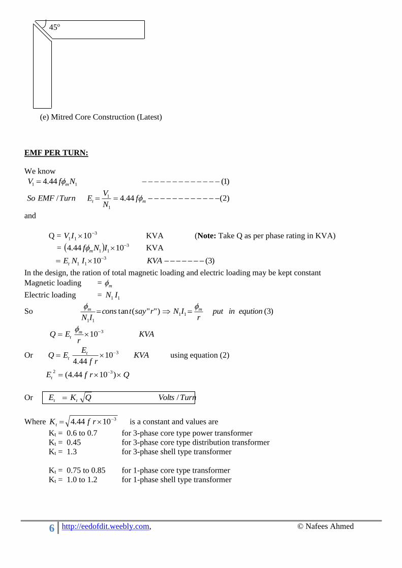
(e) Mitred Core Construction (Latest)
45o
7 http://eedofdit.weebly.com, © Nafees Ahmed
ESTIMATION OF CORE X-SECTIONAL AREA Ai
We know
)1( QKE tt
mt fE 44.4
Or )2(44.4 mit BAfE
So )3(44.4
m
t
Bf
EA
i
Now the core may be following types
d = Diameter of circumscribe circle
For Square core
Gross Area 25.022
ddd
Let stacking factor
9.0iK
Actual Iron Area
25.09.0 dAi
245.0 d (0.45 for square core and take ‘K’ as a general case) 2dK
So 2dKAi
Or K
Ad i
Graphical method to calculate dimensions of the core
Consider 2 step core
StepsofNonn
o
,1
90
oo
nei
3012
90
2.
dSinb
dCosaSo
Percentage fill
d d/√2
1-Step
Or Square- Core
2-Step
Or Cruciform- Core
3-Step Core 4-Step Core
K= 0.45 0.56 0.60 0.625
2-Step
Or Cruciform- Core
Ө b a
b
a
8 http://eedofdit.weebly.com, © Nafees Ahmed
4
2
2
d
KKd
lecircumcircofArea
coreSteppedofAreaGross i
coreStepfor
d
d4
)(4
9.0/625.0
2
2
= 0.885 or 88.5%
No of steps 1 2 3 4 5 6 7 9 11
% Fill 63.7% 79.2% 84.9% 88.5% 90.8% 92.3% 93.4% 94.8% 95.8%
ESTIMATION OF MAIN DIMENSIONS:
Consider a 3-phase core type transformer
We know output equation
KVAAKBAfQ wwmi
31033.3
So, Window area
2
31033.3m
KBAf
QA
wmi
w
where Kw =Window space factor
KVAuptoforHigherKV
Kw 1030
8
KVAuptoforHigherKV
Kw 20030
10
KVAuptoforHigherKV
Kw 100030
12
For higher rating Kw = 0.15 to 0.20
Assume some suitable range for
D = (1.7 to 2) d
Width of the window Ww = D-0.9d
Height of the window
d
L
W
D
(D-0.9d)
Ww= H
hy
3-phase core type transformer
0.9d
9 http://eedofdit.weebly.com, © Nafees Ahmed
)( w
w
Wwindowofwidth
AL )( ww AWL
Generally 42 toW
L
w
The yoke can have same area as that of the core and can be of same stepped size as core (in this case Dy=a,
hy=a). Alternatively it could be of rectangular section. In that case yoke area Ay is generally taken 10% to
15% higher then core section area (Ai), it is to reduce the iron loss in the yoke section. But if we increase the
core section area (Ai) more copper will be needed in the windings and so more cost through we are reducing
the iron loss in the core. Further length of the winding will increase, resulting higher resistance so more cu
loss.
Ay = (1.10 to 1.15) Ai
Depth of yoke Dy = a
Height of the yoke hy = Ay/Dy
Width of the core
W = 2*D +0.9 d
Or W=2Ww+3x0.9d (As Ww = D-0.9d)
Height of the core
H = L + 2*hy
Flux density in yoke
m
y
iy B
A
AB
ESTIMATION OF CORE LOSS AND CORE LOSS COMPONET OF NO LOAD CURRENT IC:
Volume of iron in core = 3*L*Ai m3
Weight of iron in core = density * volume
= i * 3*L*Ai Kg
i = density of iron (kg/m3)
=7600 Kg/m3 for normal Iron/steel
= 6500 Kg/m3 for M-4 steel
From the graph we can find out specific iron loss, pcore (Watt/Kg ) corresponding to flux density Bm in core.
So
Iron loss in core =pcore* i * 3*L*Ai Watt
Similarly
Iron loss in yoke = pyoke* i * 2*W*Ay Watt
Where pyoke = specific iron loss corresponding to flux density By in yoke
Total Iron loss Pi =Iron loss in core + Iron loss in yoke
Core loss component of no load current
Ic = Core loss per phase/ Primary Voltage
Ic 13V
Pi
2-Step
Or Cruciform- Core
b a
b
a
10 http://eedofdit.weebly.com, © Nafees Ahmed
ESTIMATION OF MAGNETIZING CURRENT OF NO LOAD CURRENT Im:
Find out magnetizing force H (atcore, at/m) corresponding to flux density Bm in the core and atyoke
corresponding to flux density in the yoke from B-H curve
matBmatB yokeYcorem /,/
So
MMF required for the core = 3*L*atcore
MMF required for the yoke = 2*W*atyoke
We account 5% AT for joints etc
So total MMF required = 1.05[MMF for core + MMF for yoke]
Peak value of the magnetizing current
1
,3N
requiredMMFTotalI peakm
RMS value of the magnetizing current
2
,
,
peakm
RMSm
II
1
,23 N
requiredMMFTotalI RMSm
ESTITMATION OF NO LOAD CURRENT AND PHASOR DIAGRAM:
No load current Io
22
mco III
No load power factor
o
co
I
ICos
The no load current should not exceed 5% of the full load current.
ESTIMATION OF NO OF TURNS ON LV AND HV WINDING
Primary no of turns tE
VN 1
1
Secondary no of turns tE
VN 2
2
Ic
Im
Io
V1=-E1
E2
Ф0
No load phasor diagram
11 http://eedofdit.weebly.com, © Nafees Ahmed
ESTIMATION OF SECTIONAL AREA OF PRIMARY AND SECONDARY CONDUCTORS
Primary current 1
3
13
10
V
QI
Secondary current 1
2
1
2
3
23
10I
N
NOR
V
QI
Sectional area of primary conductor
11
Ia
Sectional area of secondary conductor
22
Ia
Where is current the density.
Now we can use round conductors or strip conductors for this see the IS codes and ICC (Indian Cable
Company) table.
DETERMINATION OF R1 & R2 AND CU LOSSES:
Let Lmt = Length of mean turn
Resistance of primary winding
)(
)(10021.0
2
1
16
75,,1 ma
mNLR mt
dc o
oo dcacRtoR
75,,175,,1)20.115.1(
Resistance of secondary winding
)(
)(10021.0
2
2
26
75,,2 ma
mNLR mt
dc o
oo dcacRtoR
75,,275,,2)20.115.1(
Copper loss in primary winding WattRI 1
2
13
Copper loss in secondary winding WattRI 2
2
23
Total copper loss 2
2
21
2
1 33 RIRI
)(3 '
21
2
1 RRI
pRI 2
13
Where sideprimarytoreferredTotal
RRRR p
resistance
'2101
Note: Even at no load, there is magnetic field around connecting leads, tanks etc which causes additional
stray losses in the transformer tanks and other metallic parts. These losses may be taken as 7% to 10% of
total cu losses.
DETERMINATION OF EFFICIENCY:
Efficiency PowerInput
PowerOutput
LossesPowerOutput
PowerOutput
12 http://eedofdit.weebly.com, © Nafees Ahmed
100
lossCuLossIronPowerOutput
PowerOutput %
ESTIMATION OF LEAKAGE REACTANCES(X1 & X2):
Assumptions
1. Consider permeability of iron as infinity that is MMF is needed only for leakage flux path in the
window.
2. The leakage flux lines are parallel to the axis of the core.
Consider an elementary cylinder of leakage flux lines of thickness ‘dx’ at a distance x as shown in following
figure.
MMF at distance x
xb
INM x
1
11
Permeance of this elementary cylinder
L
Ao
c
mto
L
dxL (Lc =Length of winding ≈ 0.8L)
SPermeance
A
LS
o
1&
1
Leakage flux lines associated with elementary cylinder
PermeanceMd xx
Flux linkage due to this leakage flux
xx dassociatedisitwhichwithtrunsofNod
c
mto
L
dxLx
b
IN
b
IN
1
11
1
11
dx
b
xI
L
LN
c
mto
2
1
1
2
1
Flux linkages (or associated) with primary winding
1
0
2
1
1
2
1
'
1
b
c
mto dx
b
xI
L
LN
3
11
2
1
bI
L
LN
c
mto
Flux linkages (or associated) with the space ‘a’ between primary and secondary windings
aIL
LN
c
mtoo 1
2
1
We consider half of this flux linkage with primary and rest half with the secondary winding. So total flux
linkages with primary winding
2
'
11o
c
mto
L
dxLx
b
IN
1
11
x
x
a b1 b2
dx
N1I1=N2I2
Lc
MMF Distribution
L
V
H
V
13 http://eedofdit.weebly.com, © Nafees Ahmed
23
11
2
11
abI
L
LN
c
mto
Similarly total flux linkages with secondary winding
2
'
22o
23
22
2
22
abI
L
LN
c
mto
Primary & Secondary leakage inductance
23
12
1
1
11
ab
L
LN
IL
c
mt
o
23
22
2
2
22
ab
L
LN
IL
c
mto
Primary & Secondary leakage reactance
2322 12
111
ab
L
LNffLX
c
mto
2322 22
222
ab
L
LNffLX
c
mto
Total Leakage reactance referred to primary side
a
bb
L
LNfXXXX
c
mt
oP3
2 212
1
'
2101
Total Leakage reactance referred to secondary side
a
bb
L
LNfXXXX
c
mt
oS3
2 212
22
'
102
It must be 5% to 8% or maximum 10%
Note:- How to control XP?
If increasing the window height (L), Lc will increase and following will decrease b1,
b2 & Lmt and so we can reduce the value of XP.
CALCULATION OF VOLTAGE REGULATION OF TRANSFORMER:
100..2
222222
E
SinXICosRIRV oo
100/
100/ 22
22
22
22 IE
SinX
IE
CosR oo
2222 %% SinXCosR oo
TRANSFORMER TANK DESIGN:
Width of the transformer (Tank)
Wt=2D + De + 2b
Where De= External diameter of HV winding
b = Clearance width wise between HV and tank
Depth of transformer (Tank)
Dt= De + 2a
Where a= Clearance depth wise between HV and tank
14 http://eedofdit.weebly.com, © Nafees Ahmed
Height of transformer (Tank)
Ht= H + h
Where h=h1 + h2= Clearance height wise of top and bottom
b b a
a
Wt
Dt
D D
De
L
W
(D-d)
Ww H
hy
H
W
h1
h2
Ht
15 http://eedofdit.weebly.com, © Nafees Ahmed
Tank of a 3-Phase transformer
CALCULATION OF TEMPERATURE RISE:
Surface area of 4 vertical side of the tank (Heat is considered to be dissipated from 4 vertical sides of the
tank)
St= 2(Wt + Dt) Ht m2 (Excluding area of top and bottom of tank)
Let
= Temp rise of oil (35o C to 50o C)
12.5St =Total full load losses ( Iron loss + Cu loss)
So temp rise in o C tS12.5
losses load full Total
If the temp rise so calculated exceeds the limiting value, a suitable no of cooling tubes or radiators must be
provided
CALCULATION OF NO OF COOLING TUBES:
Let xSt= Surface area of all cooling tubes
Then
Losses to be dissipated by the transformer walls and cooling tube
= Total losses
losses Total5.85.12 tt xSS
So from above equation we can find out total surface area of cooling tubes (xSt)
Normally we use 5 cm diameter tubes and keep them 7.5 cm apart
At= Surface area of one cooling tube
meantubetubeld ,
Hence
No of cooling tubes t
t
A
xS
d= 5 Cm
7.5 Cm
Tank and Arrangement of Cooling tubes
Specific Heat dissipation
6 Watt/m2-0C by Radiation
6.5 Watt/m2-0C by Convection
6 W-Raditon+6.5 W-Convection=12.5 6.5*1.35 W 5.8 (35% more) Convection only
16 http://eedofdit.weebly.com, © Nafees Ahmed
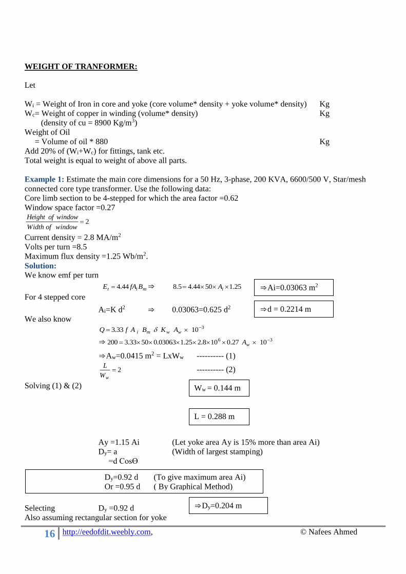
WEIGHT OF TRANFORMER:
Let
Wi = Weight of Iron in core and yoke (core volume* density + yoke volume* density) Kg
Wc= Weight of copper in winding (volume* density) Kg
(density of cu = 8900 Kg/m3)
Weight of Oil
= Volume of oil * 880 Kg
Add 20% of (Wi+Wc) for fittings, tank etc.
Total weight is equal to weight of above all parts.
Example 1: Estimate the main core dimensions for a 50 Hz, 3-phase, 200 KVA, 6600/500 V, Star/mesh
connected core type transformer. Use the following data:
Core limb section to be 4-stepped for which the area factor =0.62
Window space factor =0.27
2windowofWidth
windowofHeight
Current density = 2.8 MA/m2
Volts per turn =8.5
Maximum flux density =1.25 Wb/m2.
Solution:
We know emf per turn
mit BfAE 44.4 ⇒ 25.15044.45.8 iA
For 4 stepped core
Ai=K d2 ⇒ 0.03063=0.625 d2
We also know 31033.3 wwmi AKBAfQ
⇒ 36 1027.0108.225.103063.05033.3200 wA
⇒Aw=0.0415 m2 = LxWw ---------- (1)
2wW
L ---------- (2)
Solving (1) & (2)
Ay =1.15 Ai (Let yoke area Ay is 15% more than area Ai)
Dy= a (Width of largest stamping)
=d Cosϴ
Selecting Dy =0.92 d
Also assuming rectangular section for yoke
Dy=0.92 d (To give maximum area Ai)
Or =0.95 d ( By Graphical Method)
Ww = 0.144 m
L = 0.288 m
⇒d = 0.2214 m
⇒Ai=0.03063 m2
⇒Dy=0.204 m
17 http://eedofdit.weebly.com, © Nafees Ahmed
hy = Ay/Dy=1.15Ai/Dy (Assuming Ay=15% more than Ai)
=1.15x0.03063/0.204
Overall height H=L+hy =0.288+0.173
Overall width W= 2D+0.9d = 2Ww+3x0.9d=2x0.144+3x0.9x0.2214
Example 2: Calculate no load current of a 400 V, 50 Hz, 1-Phase, core type transformer, the particulars of
which are as follows:
Length of means magnetic path =200 Cm,
Gross core section =100 Cm2,
Joints equivalent to 0.1 mm air gap,
Maximum flux density =0.7 T,
Specific core loss at 50 Hz & 0.7 T =0.5 W/Kg,
Ampere turns =2.2 per cm for 0.7 T,
Stacking factor =0.9,
Density of core material = 7.5x 10³ Kg/m3.
Solution:
Find IC:
11 V
coreofWeightlosscoreSpecific
V
losscoreTotolIcurrentloadnoofcomponentlossCore C
400
105.710200101009.05.0 324
1
V
densitylengthAKlosscoreSpecificI
gii
C
Find Im:
We know 144.41 NBfAV mi
14 7.0101009.05044.4400 N ⇒ N1=286
11 2
1.0
2 N
mmoflengthofairgapforMMFcoreforMMF
N
MMFTotolIcomponentgMagnetizin m
2862
101.0104
17.02002.2
2
1 3
7
1
0
N
lBcoreforMMF
I
gm
m
gm lBSMMF
0
1
So No load current
22220 226.1168.0 mC III
Example 3: Design an adequate cooling arrangement for a 250 KVA, 6600/400 V, 50 Hz, 3-phase,
delta/star core type oil immersed natural cooled transformer with the following particulars:
Winding temperature rise not to exceed 500 C,
Total losses at 900 C are 5 Kw,
Tank Dimensions height x length x width = 125 x 100 x 50 (all in cm)
Oil level = 115 cm length
Sketch diagram to show the arrangement of cooling tubes.
⇒hy=0.173 m
⇒ H=0.461 m
⇒ W=0.88578 m
⇒ IC=0.168 A
⇒ Im=1.226 A
⇒ I0=1.237 A
18 http://eedofdit.weebly.com, © Nafees Ahmed
Solution:
Dissipating surface area of plain tank after neglecting the top and bottom
St=2(Wt+Dt)Ht=2(50+100)125=3.75x104 cm2=3.75 m2
C0
t
66.10675.312.5
5000
S12.5
losses load full Total
But it is required that the temp rise is not to exceed 500 C. So cooling tubes are required.
Let xSt = Surface area of all cooling tubes
losses Total5.85.12 tt xSS
⇒ xSt=6.25 m2
Surface area of one cooling tube (Assuming Tube dia = 5 cm, average height of tube =105 cm)
2, 1649.005.105.014.3 mldA meantubetubet
No of cooling tubes 381649.0
25.6
t
t
A
xS
Let the tubes to space 7 cm apart centre to centre, we will be able to accommodate 13 tubes on 100 cm side
and 6 tubes on 50 cm side.
Total tubes =2x13+2x6=38
50 Cm
7 Cm
Tank and Arrangement of Cooling tubes
100 Cm