Page 1 24-27 October 2003 Fifth International Symposium on Space Propulsion Chattanooga, Tennessee, USA Transient Mathematical Modeling for Liquid Rocket Engine Systems: Methods, Capabilities, and Experience Authors: David C. Seymour, ERC, Inc. (NASA retired) Michael A. Martin, NASA MSFC Huy H. Nguyen, NASA MSFC William D. Greene, NASA MSFC https://ntrs.nasa.gov/search.jsp?R=20050217133 2020-04-04T22:07:49+00:00Z
Transcript
Page 124-27 October 2003
Fifth International Symposium on Space PropulsionChattanooga, Tennessee, USA
Transient Mathematical Modelingfor Liquid Rocket Engine Systems:Methods, Capabilities, and Experience
Authors: David C. Seymour, ERC, Inc. (NASA retired)Michael A. Martin, NASA MSFCHuy H. Nguyen, NASA MSFCWilliam D. Greene, NASA MSFC
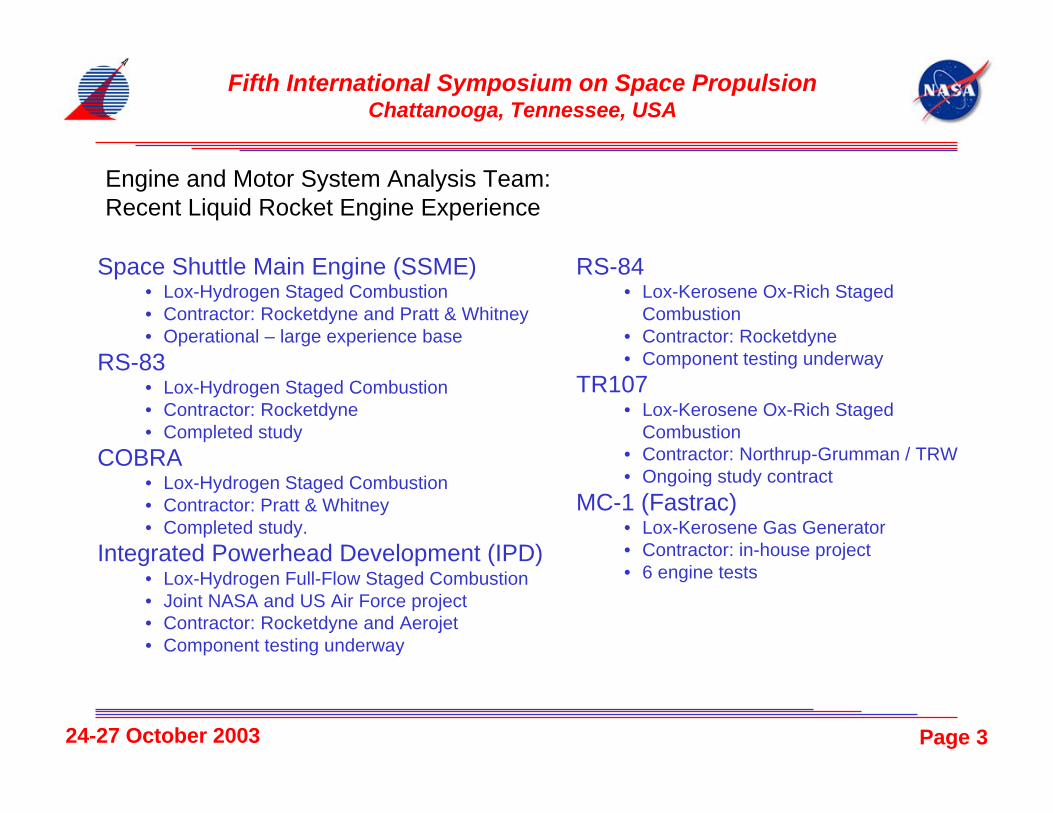
Integrated Powerhead Development (IPD)• Lox-Hydrogen Full-Flow Staged Combustion• Joint NASA and US Air Force project• Contractor: Rocketdyne and Aerojet• Component testing underway
Fifth International Symposium on Space PropulsionChattanooga, Tennessee, USA
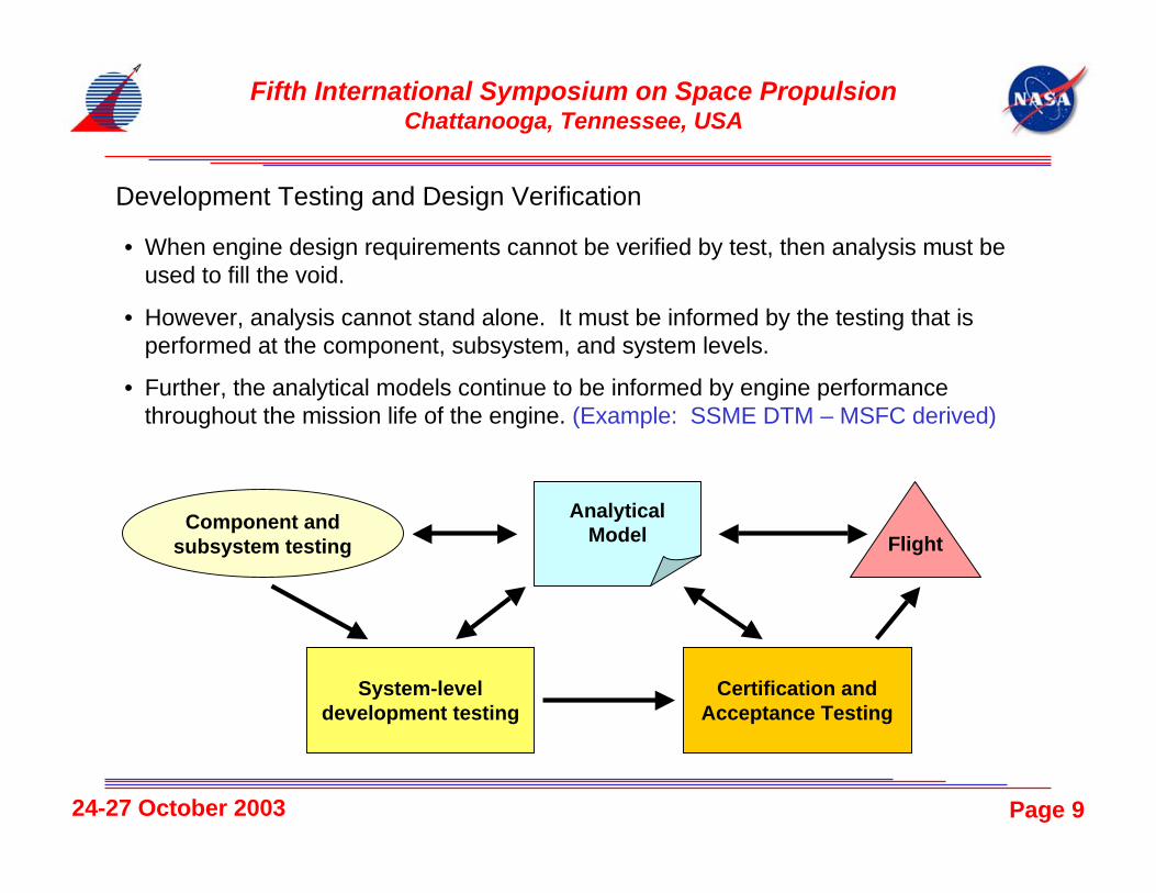
Development Testing and Design Verification
• When engine design requirements cannot be verified by test, then analysis must beused to fill the void.
• However, analysis cannot stand alone. It must be informed by the testing that isperformed at the component, subsystem, and system levels.
• Further, the analytical models continue to be informed by engine performancethroughout the mission life of the engine. (Example: SSME DTM – MSFC derived)
Component andsubsystem testing
AnalyticalModel
System-leveldevelopment testing
Certification andAcceptance Testing
Flight
Page 1024-27 October 2003
Fifth International Symposium on Space PropulsionChattanooga, Tennessee, USA
Transient Modeling Overview
Conservationof Mass
Conservationof Energy
Fluid ThermodynamicState
Conservationof Linear
Momentum
Conservationof AngularMomentum
Transfer betweenmechanical energy and
fluid energy
Heat Transfer Transfer of thermalenergy to/from fluid
CombustionTransfer of chemical
energy to fluid energy
Fluid Properties
Fluid Motion
Fluid PropertyRelations
Page 1124-27 October 2003
Fifth International Symposium on Space PropulsionChattanooga, Tennessee, USA
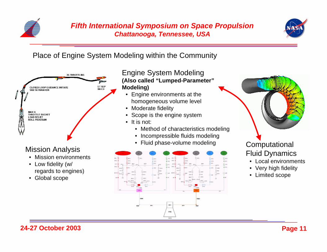
Place of Engine System Modeling within the Community
ComputationalFluid Dynamics
• Local environments• Very high fidelity• Limited scope
Fifth International Symposium on Space PropulsionChattanooga, Tennessee, USA
Conservation of Mass and Energy
in
in
h
m&
out
out
h
m&
Homogeneous Control Volume: Conditionswithin the volume determine the fluid state.
T
P
ρ0
Q& W&
( )∑∑ −=∂
∂outin mm
Vt&&1ρ =
∂∂
t
uCV( ) ( )
+− ∑∑
V
hmhm
CV
outin
ρ00 &&
( )V
mmuQW
CV
outinCVnetnet
ρ∑∑ −−+ &&&&
Page 1324-27 October 2003
Fifth International Symposium on Space PropulsionChattanooga, Tennessee, USA
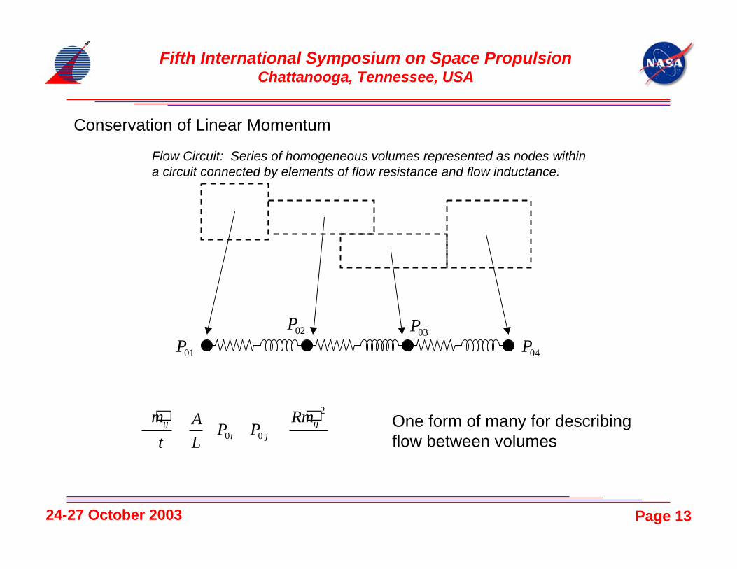
Conservation of Linear Momentum
Flow Circuit: Series of homogeneous volumes represented as nodes withina circuit connected by elements of flow resistance and flow inductance.
01P02P
03P
04P
( )
−−=
∂∂
ρ
2
00ij
jiij mR
PPL
A
t
m && One form of many for describingflow between volumes
Page 1424-27 October 2003
Fifth International Symposium on Space PropulsionChattanooga, Tennessee, USA
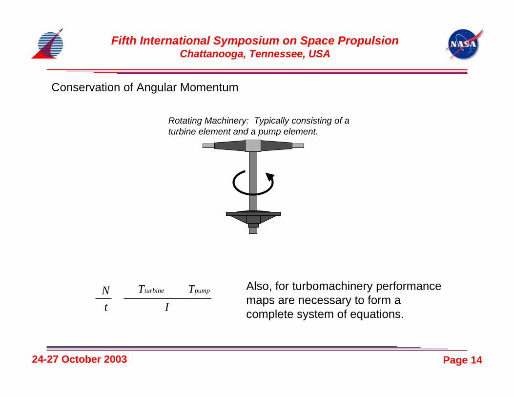
Conservation of Angular Momentum
Rotating Machinery: Typically consisting of aturbine element and a pump element.
I
TT
t
N pumpturbine ∑∑ −=
∂∂ Also, for turbomachinery performance
maps are necessary to form acomplete system of equations.
Page 1524-27 October 2003
Fifth International Symposium on Space PropulsionChattanooga, Tennessee, USA
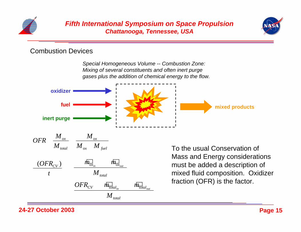
Combustion Devices
To the usual Conservation ofMass and Energy considerationsmust be added a description ofmixed fluid composition. Oxidizerfraction (OFR) is the factor.
Special Homogeneous Volume -- Combustion Zone:Mixing of several constituents and often inert purgegases plus the addition of chemical energy to the flow.
oxidizer
fuel
inert purge
mixed products
fuelox
ox
total
ox
MM
M
M
MOFR
+==
=∂
∂t
OFRCV )( ( )−
− ∑∑total
oxox
M
mmoutin
&&
( )total
totaltotalCV
M
mmOFRoutin ∑∑ − &&
Page 1624-27 October 2003
Fifth International Symposium on Space PropulsionChattanooga, Tennessee, USA
Fluid Properties Subcritical Region
Critical Point
Saturated VaporLine
Saturated LiquidLine
Log P
Nor
mal
ized
H
SupercriticalRegion
Log P
Nor
mal
ized
H
Log P
Nor
mal
ized
H
• Fluid property relations are the connectionbetween mathematics and actual fluids.
• In order to run efficient analyses, property tablesare used.
• MSFC has developed means of automaticallygenerating these tables to a specified level ofinterpolation error.
Page 1724-27 October 2003
Fifth International Symposium on Space PropulsionChattanooga, Tennessee, USA
Fluid Properties (continued)
I N S I D E T H E D O M E
Case 1 Case 2 Case 3 Case 4 Case 5 Case 6 Case 7
Case 1 Case 2 Case 3 Case 4 Case 5 Case 6 Case 7
Saturated Liquid
Saturated Vapor
• One tricky aspect of creating propellant tables is dealing with the phase-change dome.
• MSFC has developed interpolation methods for handling these cases where points ofinterest straddle the phase-change line.
Page 1824-27 October 2003
Fifth International Symposium on Space PropulsionChattanooga, Tennessee, USA
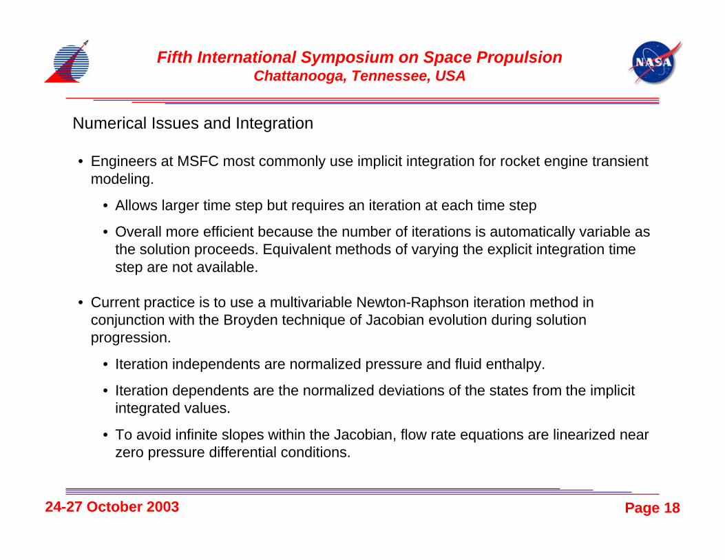
Numerical Issues and Integration
• Engineers at MSFC most commonly use implicit integration for rocket engine transientmodeling.
• Allows larger time step but requires an iteration at each time step
• Overall more efficient because the number of iterations is automatically variable asthe solution proceeds. Equivalent methods of varying the explicit integration timestep are not available.
• Current practice is to use a multivariable Newton-Raphson iteration method inconjunction with the Broyden technique of Jacobian evolution during solutionprogression.
• Iteration independents are normalized pressure and fluid enthalpy.
• Iteration dependents are the normalized deviations of the states from the implicitintegrated values.
• To avoid infinite slopes within the Jacobian, flow rate equations are linearized nearzero pressure differential conditions.
Page 1924-27 October 2003
Fifth International Symposium on Space PropulsionChattanooga, Tennessee, USA
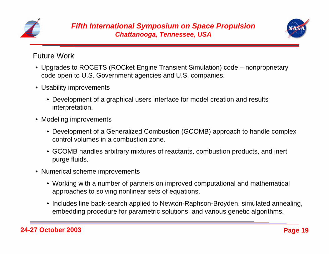
code open to U.S. Government agencies and U.S. companies.
• Usability improvements
• Development of a graphical users interface for model creation and resultsinterpretation.
• Modeling improvements
• Development of a Generalized Combustion (GCOMB) approach to handle complexcontrol volumes in a combustion zone.
• GCOMB handles arbitrary mixtures of reactants, combustion products, and inertpurge fluids.
• Numerical scheme improvements
• Working with a number of partners on improved computational and mathematicalapproaches to solving nonlinear sets of equations.
• Includes line back-search applied to Newton-Raphson-Broyden, simulated annealing,embedding procedure for parametric solutions, and various genetic algorithms.
1
Transient Mathematical Modeling for Liquid Rocket Engine Systems:Methods, Capabilities, and Experience
Michael A. Martin, Huy H. Nguyen, and William D. GreeneNASA Marshall Space Flight Center, Huntsville, AL
David C. Seymour (NASA-retired)ERC, Inc., Huntsville, AL
Abstract
The subject of mathematical modeling of the transient operation of liquid rocket engines ispresented in overview form from the perspective of engineers working at the NASA MarshallSpace Flight Center. The necessity of creating and utilizing accurate mathematical models aspart of liquid rocket engine development process has become well established and is likely toincrease in importance in the future. The issues of design considerations for transient operation,development testing, and failure scenario simulation are discussed. An overview of thederivation of the basic governing equations is presented along with a discussion of computationaland numerical issues associated with the implementation of these equations in computer codes.Also, work in the field of generating usable fluid property tables is presented along with anoverview of efforts to be undertaken in the future to improve the tools use for the mathematicalmodeling process.
Nomenclature
dt Time increment
0h Total Enthalpy
m� Mass Flow Ratet Timeu Internal Energyu Fluid Velocity
A AreaCV Control Volume
E� Energy FluxF ForceI Moment of Inertia
L LengthM MassMR Mixture RatioN Rotational VelocityOFR Oxidizer Fraction
0P Total Pressure
Q� Heat Transfer
R Fluid ResistanceT Shaft TorqueV Volume
W� Work
Y Generic Fluid Propertyρ Densityτ Time Constant
This is a work of the U.S. Government and is not subject tocopyright protection in the United States. Foreign copyrightsmay apply.
2
Introduction
The development of complex and expensivemachinery such as liquid propellant rocketengines within the real world of limitedbudgets requires that analytical tools be usedto facilitate the process as much as possible.Rocket engine project managers expect andplan to have detailed engine transient analysisavailable early in their development program.Because building hardware and conductingtesting is exorbitantly expensive, theytypically budget only a few tests to developthe engine start and shutdown sequences andthey do not plan for the possibility of majorhardware damage as part of the process. Theycan do this because the U.S. rocket enginecommunity has actively developed analyticaltools to take advantage of the tremendousincrease in computer power over the lasttwenty years.
At the NASA Marshall Space Flight Center(MSFC), engineers recognized about twodecades ago that new ways of rapidlydeveloping moderately detailed models of newengines was needed. Although monetaryresources have been very limited, engineershave continued to pursue this goal and todaypossess very powerful tools to offer theprospective liquid rocket engine programmanager.
Despite all of the work to date, however,rocket engine transient analysis remains a verychallenging discipline. While steady-statetools have evolved almost to the point that anyengineer can use them, transient analysis stillrequires dedicated specialists experienced intransient analysis to get useful results. Thetransient analyst must develop and manage alarge amount of input data, describe complexphysics, and deal with challengingcomputational and numerical issues. Allmathematical modeling requires the utilizationof some level of approximation and selecting
the right approximation to the complexphysics involved in transient analysis iscritical and often unique to the model beingdeveloped. The tools developed at MSFCallow the specialist to choose betweencommon generic approximations or generateand implement their own versions.
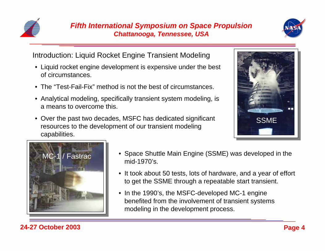
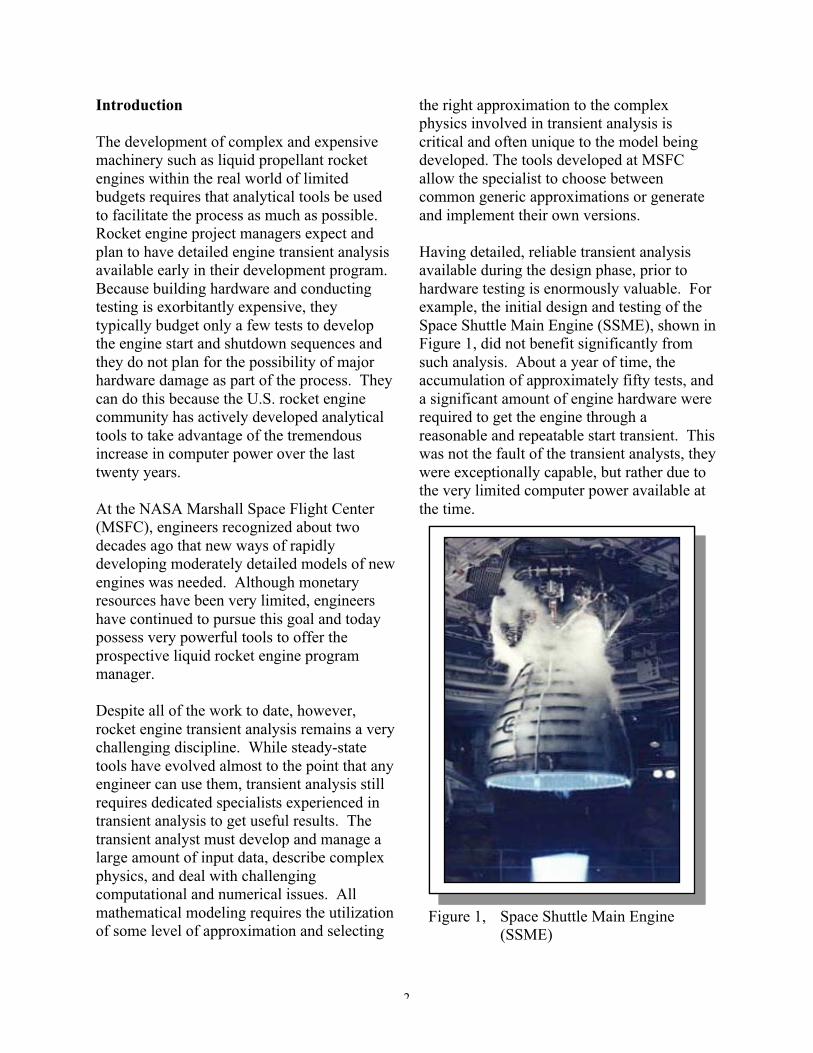
Having detailed, reliable transient analysisavailable during the design phase, prior tohardware testing is enormously valuable. Forexample, the initial design and testing of theSpace Shuttle Main Engine (SSME), shown inFigure 1, did not benefit significantly fromsuch analysis. About a year of time, theaccumulation of approximately fifty tests, anda significant amount of engine hardware wererequired to get the engine through areasonable and repeatable start transient. Thiswas not the fault of the transient analysts, theywere exceptionally capable, but rather due tothe very limited computer power available atthe time.
Figure 1, Space Shuttle Main Engine(SSME)
3
Subsequent engine development programs,such as the MSFC-developed MC-1 (alsocalled Fastrac), shown in Figure 2, althoughfew in number and of simpler designs, havedemonstrated dramatically lower developmentcosts in part due to advances in enginetransient modeling analyses and the computersto drive them. Further, this approach ofemphasizing transient model developmentearly in the engine design period has becomethe standard process followed for the nextgeneration of rocket engines being pursuedthrough the NASA Next Generation LaunchTechnology Program.
Design Considerations
Typical design practice for liquid rocketengines dictates that with the exception forsurge pressures and valve margins, mostengine components are designed to meetsteady-state performance requirements. Thus,most engine elements are not been designedwith start and shutdown transientenvironments in mind. Thus, it becomes thetask of the transient analyst to take givencomponent capabilities and find start andshutdown sequences that are safe for the
components and still meets all otherperformance requirements.
During the preliminary design phase, enginesystem analysis may be required to set basicengine requirements. For example, in the jointNASA and Air Force Integrated PowerheadDevelopment (IPD) engine program, transientsystem analysis showed that an engine startsequence based on tank pressure head alonewas a risky proposition. This analysis wasused to justify the inclusion of provisions forturbopump spin-assist into the engine andfacility development.
For most engine development programs, as theengine design matures so does the modeldetail and fidelity. Model sensitivity analysescan point to component characteristics mostcritical to successful, repeatable starts andshutdowns.
An example of this can be found during theMC-1 development. Early flow tests of themain propellant valves showed that the valveswere “jerking” open instead of opening in asmooth, controlled manner. Simulating thisvalve behavior in the engine transient modelshowed that this was an undesirable condition.The quickly opening valves, combined with ahelium spin-start on the turbine, resulted pumpcavitation. Using the same codes that are usedfor engine transient models, a detailedtransient model of the pneumatic valve itselfwas able to duplicate the phenomenon. Onepotential fix was to add a rotary damper to thevalve. This fix was added to the valve modelto verify the results prior to testing. Afteradding the rotary damper to the actual valve,the valves opened smoothly. Thus, the modelaided in the design of the valve prior to enginehot-fire testing. The model was used not onlyto show the effects of the valve design on theengine system, but was also used in fixing thedesign flaw.
Figure 2, MC-1 (Fastrac) thrust chamberassembly being tested at MSFC
4
The transient system mathematical modelpredictions are key inputs into the initialengine system test plan and are a vital part ofpost-test analysis. Final engine start andshutdown sequences are, of course, verified bytest. However, some off-nominal start orshutdowns may be impossible, impractical, orunsafe to demonstrate with actual enginehardware and must be verified by the transientmodel alone.
Design Verification and Operation
When meeting the engine design requirementsthat cannot be verified by test, it is standardpractice to use analysis to fill the void. Thetransient engine model is anchored to theavailable test data, specifically for conditionsas close as possible to the verificationcondition, and then used to predict the engineoperation at the verification condition.
This approach was taken for SSME to verifysafe engine flight shutdown under liquidoxygen depletion conditions. Several attemptsto simulate the zero-g flight engine feedlineconditions on a ground test stand were made.However, none were judged to satisfactorilysimulate the behavior of the saturated liquidoxygen in the feedline and its effect on thelow-pressure liquid oxygen pumpperformance. The transient analysis on thisissue performed by Rocketdyne, the SSMEprime contractor, was a vital part of the SSMEshutdown performance verification for flight.
Verification of safe shutdown at any point intime during engine operation is another areathat usually requires analysis. Such ananalysis was not formally performed for theSSME during engine development. Afterabout twenty years and several thousandengine tests, a redline engine cut occurred in aground test during the engine start sequence ata slightly different time than previously tested.This shutdown resulted in a control valve
exceeding its operating limit. The valve wascommanded to close but failed to do so underthe conditions and the result was extensiveengine damage. Because of this enginefailure, the software controlling the SSMEshutdown sequence was modified to avoidsuch a situation in the future. Subsequenttransient analyses verified the inherent dangerin the original sequence and have been usedextensively to examine all other pointsthroughout the mission profile.
Failure Scenario Considerations
For liquid rocket engines, many hardwarefailure modes are classified as inherentlycatastrophic and are not extensively analyzed.The power unleashed and the speed at whichthe failures occur are so great that theypreclude any possibility of mitigation orminimization. This is simply the nature of thefield. However, there are a very large numberof failure modes that are not inherentlycatastrophic but could lead either to an engineshutdown or to engine performancesufficiently off nominal as to prevent thevehicle from fulfilling mission objectives.Many of these failures are too costly or toorisky to verify by test and must be assessed byengine system transient analysis.
Some examples from the SSME programinclude degraded control valve actuatorperformance, propellant or combustion gasleaks, check valve leaks, flow restrictions dueto contamination, and degraded turbopumpperformance.
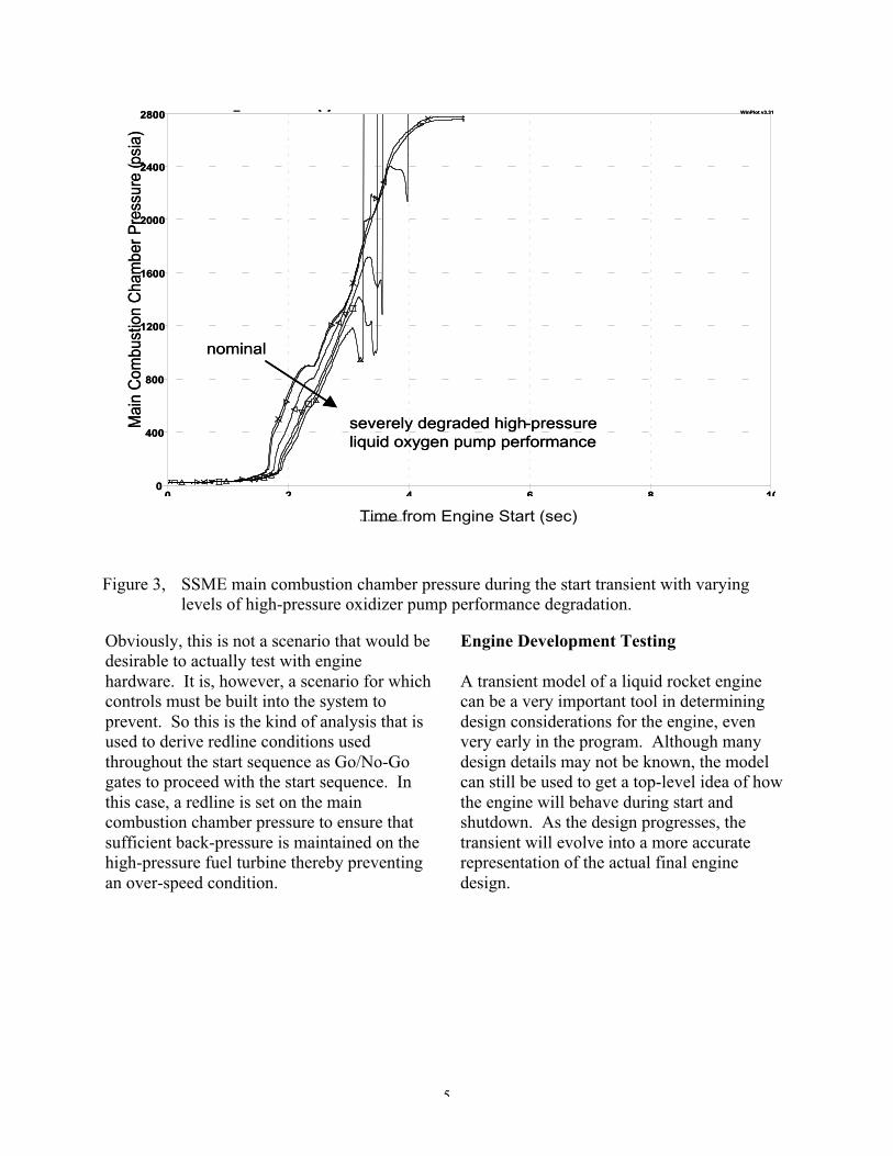
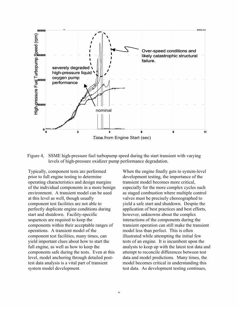
The specific example of an engine start beingattempted under the conditions of severelydegraded turbopump performance is show inFigures 3 and 4. In this case, the performanceof the SSME high-pressure liquid oxygenpump is degraded to differing degrees over aseries of transient model runs. After a certainamount of performance degradation, the pump
5
is no longer capable of feeding sufficientpropellant to the main combustion chamber.This results in insufficient pressure beingmaintained on the downstream side of thehigh-pressure fuel turbine. Thus, the high-pressure fuel turbopump has an effective surgein power and this results in a severe over-speed condition and likely catastrophicstructural failure of the fuel turbopump asshown in Figure 4.
Obviously, this is not a scenario that would bedesirable to actually test with enginehardware. It is, however, a scenario for whichcontrols must be built into the system toprevent. So this is the kind of analysis that isused to derive redline conditions usedthroughout the start sequence as Go/No-Gogates to proceed with the start sequence. Inthis case, a redline is set on the maincombustion chamber pressure to ensure thatsufficient back-pressure is maintained on thehigh-pressure fuel turbine thereby preventingan over-speed condition.
Engine Development Testing
A transient model of a liquid rocket enginecan be a very important tool in determiningdesign considerations for the engine, evenvery early in the program. Although manydesign details may not be known, the modelcan still be used to get a top-level idea of howthe engine will behave during start andshutdown. As the design progresses, thetransient will evolve into a more accuraterepresentation of the actual final enginedesign.
Figure 3, SSME main combustion chamber pressure during the start transient with varyinglevels of high-pressure oxidizer pump performance degradation.
6
Typically, component tests are performedprior to full engine testing to determineoperating characteristics and design marginsof the individual components in a more benignenvironment. A transient model can be usedat this level as well, though usuallycomponent test facilities are not able toperfectly duplicate engine conditions duringstart and shutdown. Facility-specificsequences are required to keep thecomponents within their acceptable ranges ofoperations. A transient model of thecomponent test facilities, many times, canyield important clues about how to start thefull engine, as well as how to keep thecomponents safe during the tests. Even at thislevel, model anchoring through detailed post-test data analysis is a vital part of transientsystem model development.
When the engine finally gets to system-leveldevelopment testing, the importance of thetransient model becomes more critical,especially for the more complex cycles suchas staged combustion where multiple controlvalves must be precisely choreographed toyield a safe start and shutdown. Despite theapplication of best practices and best efforts,however, unknowns about the complexinteractions of the components during thetransient operation can still make the transientmodel less than perfect. This is oftenillustrated while attempting the initial fewtests of an engine. It is incumbent upon theanalysts to keep up with the latest test data andattempt to reconcile differences between testdata and model predictions. Many times, themodel becomes critical in understanding thistest data. As development testing continues,
Over-speed conditions and likely catastrophic structural failure.
nominal
Figure 4, SSME high-pressure fuel turbopump speed during the start transient with varyinglevels of high-pressure oxidizer pump performance degradation.
7
the model should become more refined andconsistently accurate.
Once the engine is well into developmenttesting, the model can be used to refine thestart and shutdown sequences in an attempt tominimize damaging characteristics of thetransients. Examples of this are theminimization of thermal ignition spikes incombustion devices and pressure surges inlines. It is the responsibility of the analyst torecommend ways to improve the operationalsequences in order to optimize the start andshutdown. This process continues even as theengine enters the flight program since thetransient model becomes a primary tool in theunderstanding of sequence change impact andthe resolution of anomalous situations.
A good example of a transient model utilizedand maintained long after an engine has beendemonstrated in flight is the SSME DigitalTransient Model (DTM). This model is keptunder configuration control and is used toresolve transient performance issues after overtwenty years of successful flight use. It isused to validate proposed changes to thebaseline start and shutdown sequences and toevaluate real and hypothetical anomaloussituations.
Thus, a transient model of a liquid rocketengine is important through all phases of anengine program. In fact, as the modeling toolsbecome better and more sophisticated in thefuture, their importance is likely to increase.
Transient Modeling Physics and BasicModeling Strategy
Transient modeling of a liquid propellantrocket engine system is typically based uponthe assumption of approximating the engine asa series of homogenous control volumes.Within each volume the principles of theconservation of mass and energy are applied.
This includes the incorporation of thermalanalysis, where appropriate, when temperaturechanges in the hardware itself is influencingthe fluid conditions. Further, these volumesare connected to create a fluid flow network towhich the principle of the conservation oflinear momentum is applied as a governingequation to determine the transport of fluidfrom one volume to another.
Finally, because of the unique aspects ofliquid typical, high-power rocket enginesystems, special considerations must be madefor the inclusion of rotating machinery and theexistence of combustion zones. Rotatingmachinery, otherwise called turbomachinery,is included within the solution process via theuse of the conservation of angular momentum.Combustion zones, called combustion devices,require the additional consideration of theaddition of chemical energy into the systemand the change in the chemical content of theworking fluids.
All of this together constitutes the completesystem that must be accurately modeledthrough mathematical and computationalanalysis.
Conservation of Mass
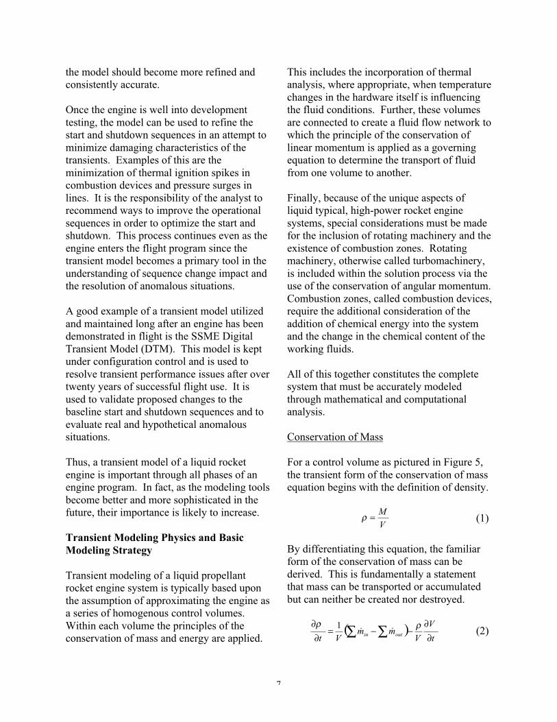
For a control volume as pictured in Figure 5,the transient form of the conservation of massequation begins with the definition of density.
V
M=ρ (1)
By differentiating this equation, the familiarform of the conservation of mass can bederived. This is fundamentally a statementthat mass can be transported or accumulatedbut can neither be created nor destroyed.
( )t
V
Vmm
Vt outin ∂∂
−−=∂∂
∑∑ ρρ��1 (2)
8
Equation 2 is the form of the conservation ofmass equation most useful for transientmodeling. For most applications of thisequation, the volume is fixed and, therefore,the equation simplifies to:
( )∑∑ −=∂∂
outin mmVt
��1ρ(3)
This equation gives one the current rate ofchange of density based on the current valuesof flowrates entering and leaving a controlvolume. This is the first state equation.
Conservation of Energy
The second state equation applicable to thecontrol volume pictured in Figure 5 is derivedfrom the first law of thermodynamics. Just aswith mass, the statement of conservation ofenergy is that the rate of flow of energy into acontrol volume minus the rate of flow ofenergy out equals the rate of energyaccumulation. Energy is neither created nordestroyed. In mathematical terms thisbecomes,
netnetoutinCV QWEEt
E ���� ++−=∂
∂(4)
Typically, potential energy in the form ofelevation effects is ignored and kinetic energyin the form of fluid velocity is included withinthe formulation of total enthalpy terms. Thisleads to the form used for transient analysis,
=∂
∂t
uCV ( ) ( )+
−∑∑V
hmhm
CV
outin
ρ00 ��
( )V
mmuQW
CV
outinCVnetnet
ρ∑∑ −−+ ���� (5)
Within the term netQ� exists the possibility of
heat transfer between the fluid and the enginehardware. This is an important factor fortransient analysis, particularly when dealingwith cryogenic propellants.
Equation 5 is the state equation for the internalenergy of the control volume. Combined withEquation 3, these two derivative equationsallow for the determination of two
in
in
h
m�
out
out
h
m�
Homogeneous Control Volume: Conditions within the volume determine the fluid state.
T
P
ρ0
Q�Apply:
• Conservation of Mass• Conservation of Energy• Fluid State Relations
W�
in
in
h
m�
out
out
h
m�
Homogeneous Control Volume: Conditions within the volume determine the fluid state.
T
P
ρ0
Q�Apply:
• Conservation of Mass• Conservation of Energy• Fluid State Relations
W�
Figure 5, Homogeneous control volume with inputs and outputs.
9
independent states of the fluid, from whichany other required thermodynamic propertiescan be determined.
Conservation of Linear Momentum
So far, only the state of the fluid can bedetermined from the equations derived.Motion of the fluid from volume to volume isbased upon Newton's Second Law formulatedfor a control volume.
( ) ∑= Fdt
umd ˆ(6)
This is a statement of the conservation oflinear momentum, which is simply that themomentum of fluid will remain unchangedunless acted upon by a force. Within thecontext of transient analysis, the forcestypically acting upon the fluid are pressureand viscous effects.
There are a number of different flow processes
that can be modeled. The most common andthe most general is the flow through a networkrepresented by a series of homogeneouscontrol volumes. A simple representation ofthis is shown in Figure 6 where the volumesact as nodes in the network. Solution of thisnetwork involves the transformation ofEquation 6 into an analogy of electrical circuitsolution methods.
( )⎥⎥⎦
⎤
⎢⎢⎣
⎡−−=
∂∂
ρ
2
00ij
jiij mR
PPL
A
t
m ��(7)
Where i and j represent two nodes within thenetwork and the variables A and L representeffective cross-sectional area and node-to-node linear distance. For many problems suchas flow in a duct these parameters haveobvious values but for problems involvingcomplex flow geometry situations,determining the appropriate values for thesefactors can become problematic. The engineermust often depend upon experience,
Flow Circuit: Series of homogeneous volumes represented as nodes within a circuit connected by elements of flow resistance and flow inductance.
Apply:• Conservation of Linear Momentum
01P02P 03P
04P
Flow Circuit: Series of homogeneous volumes represented as nodes within a circuit connected by elements of flow resistance and flow inductance.
Apply:• Conservation of Linear Momentum
01P02P 03P
04P
Figure 6, Modeling representation of a fluid flow circuit
10
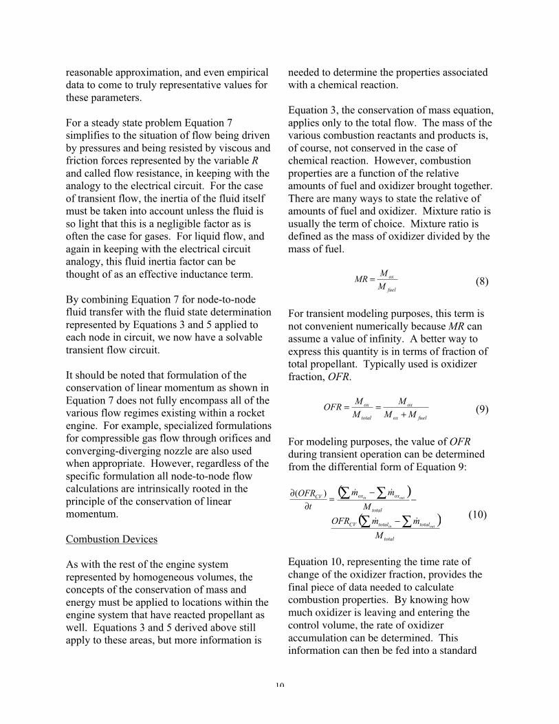
reasonable approximation, and even empiricaldata to come to truly representative values forthese parameters.
For a steady state problem Equation 7simplifies to the situation of flow being drivenby pressures and being resisted by viscous andfriction forces represented by the variable Rand called flow resistance, in keeping with theanalogy to the electrical circuit. For the caseof transient flow, the inertia of the fluid itselfmust be taken into account unless the fluid isso light that this is a negligible factor as isoften the case for gases. For liquid flow, andagain in keeping with the electrical circuitanalogy, this fluid inertia factor can bethought of as an effective inductance term.
By combining Equation 7 for node-to-nodefluid transfer with the fluid state determinationrepresented by Equations 3 and 5 applied toeach node in circuit, we now have a solvabletransient flow circuit.
It should be noted that formulation of theconservation of linear momentum as shown inEquation 7 does not fully encompass all of thevarious flow regimes existing within a rocketengine. For example, specialized formulationsfor compressible gas flow through orifices andconverging-diverging nozzle are also usedwhen appropriate. However, regardless of thespecific formulation all node-to-node flowcalculations are intrinsically rooted in theprinciple of the conservation of linearmomentum.
Combustion Devices
As with the rest of the engine systemrepresented by homogeneous volumes, theconcepts of the conservation of mass andenergy must be applied to locations within theengine system that have reacted propellant aswell. Equations 3 and 5 derived above stillapply to these areas, but more information is
needed to determine the properties associatedwith a chemical reaction.
Equation 3, the conservation of mass equation,applies only to the total flow. The mass of thevarious combustion reactants and products is,of course, not conserved in the case ofchemical reaction. However, combustionproperties are a function of the relativeamounts of fuel and oxidizer brought together.There are many ways to state the relative ofamounts of fuel and oxidizer. Mixture ratio isusually the term of choice. Mixture ratio isdefined as the mass of oxidizer divided by themass of fuel.
fuel
ox
M
MMR = (8)
For transient modeling purposes, this term isnot convenient numerically because MR canassume a value of infinity. A better way toexpress this quantity is in terms of fraction oftotal propellant. Typically used is oxidizerfraction, OFR.
fuelox
ox
total
ox
MMM
MM
OFR+
== (9)
For modeling purposes, the value of OFRduring transient operation can be determinedfrom the differential form of Equation 9:
=∂
∂t
OFRCV )( ( )−
−∑∑total
oxox
M
mmoutin
��
( )total
totaltotalCV
M
mmOFRoutin ∑∑ − �� (10)
Equation 10, representing the time rate ofchange of the oxidizer fraction, provides thefinal piece of data needed to calculatecombustion properties. By knowing howmuch oxidizer is leaving and entering thecontrol volume, the rate of oxidizeraccumulation can be determined. Thisinformation can then be fed into a standard
11
chemical equilibrium routine [Gordon, 1971and 1984] to determine the properties ofresultant high-energy chemical reactionproducts.
Turbomachinery
The other piece of hardware that is typical inhigh-power liquid rocket engine systems thatrequires special attention is turbomachinery.The energy transfer accomplished by thismachine can be modeled through a focus onthe rotational acceleration of the shaftconnecting the turbine to the pump. This isillustrated in Figure 7. The angularacceleration of a shaft is determined from theapplication of the conservation of angularmomentum.
I
TT
tN pumpturbine ∑∑ −
=∂∂ (11)
In order to determine the summation of torquemoments applied to the shaft, the model must
additionally have information relating fluidproperty and flow parameters in both theturbine and the pump to values of torque.These are collectively referred to asturbomachinery maps. The determination ofthese maps is largely an empirical matter thedetails of which are left to the componentdevelopers.
Integration and Solution
With all of the necessary governing equationsderived for the various elements of the enginesystem, the next step becomes the generationof a numerical means of solving theseequations.
Upon first impression, performing an explicitEulerian integration of the state equationswould appear to be the most straightforwardway of completing the transient analysis. Thiswould consist of stepping through time usingthe conditions of the previous time step todrive the calculations in the current time step.
Apply:• Conservation of Angular Momentum• Pump and turbine relationships between fluid
work and shaft torque
Rotating Machinery: Typically consisting of a turbine element and a pump element.
Apply:• Conservation of Angular Momentum• Pump and turbine relationships between fluid
work and shaft torque
Rotating Machinery: Typically consisting of a turbine element and a pump element.
Figure 7, Modeling of rotating hardware element of turbomachinery
12
However, in practice, the time step used forsuch an integration scheme must be verysmall. Larger time steps can be taken byusing implicit methods. One such approach isthe trapezoidal integration as represented inEquation 12.
⎥⎦
⎤⎢⎣
⎡⎟⎠⎞⎜
⎝⎛+⎟
⎠⎞⎜
⎝⎛+=
newoldoldnew dt
dYdtdY
dtYY 6.04.0
(12)
Other similar schemes are also considered. Itshould be noted that an iteration loop isrequired as the part of such a scheme becausethe value of the state at the new point is afunction of the derivative evaluated at thecurrent point, which requires knowing thevalue of the state at the new point. For thisreason, the state is iterated until the guessedvalue is equal to the predicted value.
It has been found that using density and thefluid internal energy, the two most obvious
choices, as the iteration parameter can benumerically unstable. Instead, pressure andenthalpy are used as the iterated statevariables. This scheme works so long asdensity and internal energy can be determinedfrom pressure and enthalpy. However,because pressure and enthalpy are independentproperties, this obstacle is easily overcome.
Fluid Properties
A critical element of transient modeling ofliquid rocket engines is the utilization ofaccurate fluid properties. Through thederivation of the governing conservationequations all of the various fluid propertiesexisting as variables within the equationsremain generic with no tie to actualpropellants. It is through the use of accuratefluid property routines that the transient modelis transformed from a mathematical exercise
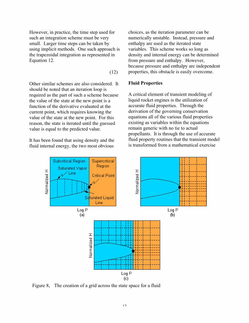
Figure 8, The creation of a grid across the state space for a fluid
13
to a representation of an actual engine. Withthis in mind, a great deal of effort has beenspent, and continues to be spent, in thecreation of efficient and accurate and usableproperty routines. This section describes arecent effort in which property tables in andaround the region of propellant phase changewere developed in a unique way.
First, the program goes through saturatedliquid and vapor lines to determine thenecessary number of pressure points and theirvalues so that the interpolation error would bewithin the specified error. This is illustratedin Figure 8a. The property data is divided intotwo regions: sub-critical and supercritical.After obtaining the pressure values forsaturated lines, the program then determinespressure-enthalpy values for the supercriticalregion as shown in Figure 8b. For the sub-critical region, the pressure values are thesame as the pressure values of the saturatedlines, and likewise the enthalpy values werethe same as the enthalpy values of thesupercritical region as in Figure 8c.
For the supercritical region, a regular linearinterpolation routine can be used to retrieveproperty data from the property tables;however, for the sub-critical region, a specialinterpolation routine is required for caseswhere one or more data points were inside thephase-change dome. A new interpolationroutine was derived to handle both sub-criticaland supercritical regions. Figure 9 showsfourteen possible cases near the saturated lineswhere the special interpolation routine is
Figure 9, Special interpolation situations around the liquid and vapor saturation lines
14
required in order to retrieve reasonableproperty data from the generated tables. Forexample, Case 2 represents situationstraddling the saturated vapor line. Thebottom 2 data points within the interpolationrectangle (unshaded) lie inside the phase-change dome; therefore, they will not be usedin the interpolation process. Instead, only thetop 2 data points (shaded) are used along withdata along the saturated vapor line. In thismanner the inherent errors associated withusing linear interpolation around a zone ofdiscontinuity can be avoided.
Numerical Solution Issues
The application of the conservation equationsand the first law of thermodynamics asdescribed above results in a system equationsthat must be solved in order to define the stateof the engine at each point in time. Themethod currently used at NASA MSFC fordoing this is based on the Newton-Raphsonscheme as applied to a system of non-linearequations. Newton-Raphson requires thegeneration of a Jacobian matrix – a collectionof the slopes of the equations with respect toeach parameter being iterated. Thesederivatives are determined analytically byindividually perturbing each variable andmeasuring the response of the system ofequations to that perturbation. This Jacobianmatrix is then used by the solver to iterate thevariables until convergence. The theory ofNewton-Raphson is well documented;however, in practice, several problems canarise.
One such problem is that the Jacobian is onlyvalid at the initial values of the independents.As the solution progresses, the Jacobianmatrix will change. Evaluating the Jacobian iscostly in terms of computational resources.For this reason, reevaluation of the Jacobianas the solution progresses is not feasible. Thisproblem is overcome by making use of the
Broyden technique [Broyden, 1965]. This is atechnique to evolve the Jacobian matrixduring solution progression.
In order to overcome issues of numericalstiffness, convergence of the system isdetermined based on percent errors, notabsolute errors. This in turn creates a problemwhen the variable being used in thedenominator of the percent error equationapproaches zero. In practice, this obstacle isovercome by using normalizers. A normalizeris essentially a limit placed on thedenominator to prevent it from going to zero.However, when a normalizer value is invoked,the percent error starts to approach an absoluteerror, as opposed to a percent error so thisprocess must be invoked with considerablecare.
When modeling a transient fluid network,progress in the solution through time is madeusing a time step, or dt. If the dt is too small,the solution takes an excessive amount of timeto progress. However, if the dt is too large,the iterations may fail or the results maycontain errors. Thus, a balance must be struckbetween these two extremes. However, evenafter recognizing this need for balance thereexists the problem that the required dt maychange depending on what is happening at thattime (valves opening/closing, ignition events,etc.). There are no rigorous methods todetermine to optimum dt. However, onemethod used to gauge the time step relative tothe system is the concept of the time-constant.The time-constant of a control volume is themass stored in the volume divided by the flowrate through the volume ( mM �=τ ). Thisterm is a rough approximation of the time afluid particle resides within the controlvolume. It is also a measure of how quicklythe volume responds to changes. The timeconstant can be employed to determine if thedt is within the correct order of magnitude. Ifthe time constant of a control volume is much
15
smaller than the time-step being used, thisimplies that the changes to the control volumemay not be sufficiently captured by the time-step. Another technique is automatic dtreduction. When a solution begins toexperience convergence problems, the codeautomatically reduces the time-step to attemptto obtain a converged solution.
Another common problem occurs when flowrates approach zero. Since flow rate isproportional to the square root of the pressuredifferential, the slope of changes in flow rateas a function of differential pressureapproaches infinity when the differentialpressure approaches zero. This large slopecreates havoc on the Newton-Raphsonsolution methodology. Typically, toovercome this issue, the flow rate equation islinearized near zero flow (in other words, nearzero differential pressure) to create a finite andconstant slope in this region.
Future Work
The process of improving transientmathematical modeling capabilities in thefuture falls into three basic categories:
• Improvements of the usability of themodeling tools
• Improvements to the approximations usedin the modeling to represent complexsystems
• Improvements to the numerical schemesused to solve the derived equations anddeveloped computer code.
The task of assembling a completemathematical model of a complex liquidrocket engine system is a time-consumingprocess. The use of a modular format forpieces of modeling code that apply toparticular hardware elements is wellestablished and is of great utility. However,the text-based format currently used at NASA
MSFC for the assembly of these modules isnot easy or quick. To overcome thislimitation, work has begun on thedevelopment of a graphical users interface(GUI) for this initial assembly procedure. It ishoped that the use of GUI will cut down thebasic assembly time and allow analysts tospend a greater amount of time dealing withthe more technical aspects of their modelingtasks.
The complex environments contained withinliquid rocket engine components require thatthe analyst make approximations of reality inorder to generate a solvable problem. Onearea where improvements are being made tothis approximation is in the combustiondevices. Engineers at NASA MSFC aredeveloping a Generalized Combustion(GCOMB) approach that can determine theeffective mixed properties of multipleconstituents within a volume. This is ofparticular importance in volumes potentiallycontaining combustion reactants, combustionproducts, and inert gas purge flows. Thisovercomes many limitations of previousmethods wherein artificial volumes weresometimes added to account for purge flowsand real fluid properties could not be usedthroughout the transient operation regimesbeing modeled.
And finally, work is being pursued in the areaof using more advanced computational andmathematical techniques in the solution of thenonlinear sets of equations used to representthe liquid rocket engine system. Incoordination with industry partners andexperts from academia, and with support fromour Air Force partners, NASA MSFCengineers are examining a number ofadvanced methods. These include line back-search applied to the currently usedNewton/Broyden method [Press, 1986](pictured in Figure 10), simulated annealing,
16
embedding procedure for parametric solutions,and various genetic algorithms.
Summary / Conclusions
The subject of liquid rocket engine systemtransient modeling could, if covered in detail,fill several entire textbooks. The reader isdirected to the Additional Reading section forjust such treatments. It was the purpose of theauthors here to present some of the basicprinciples and some clear rationale why thissubject is such a vital aspect of liquid rocketengine development and utilization. Whereasrocket engines are designed to perform atsteady state conditions, the only way to get toand from that point is through the potentiallytreacherous processes of engine start andengine shutdown.
In the past, before the widespread use of high-speed computers, many liquid rocket engine
programs relied on the process of trial anderror in developing start and shutdownsequences. Obviously, this approach canwork but it is costly, time consuming, and canoften result in multiple hardware failures.Further, such an approach cannot fully exploreall of the hypothetical failure scenarios thatmight be lurking just on the edges of nominalperformance. Only through the use oftransient simulation can these shortfalls beovercome.
However, even with the use of high-speedcomputers and even with the basic physics ofthe problem well established, the task of theanalyst is hardly straightforward. Everysystem is unique and presents specialchallenges. Because any mathematicalmodeling task is intrinsically a process ofmaking reasonable approximations of reality,the analyst must constantly reevaluate thesufficiency and completeness of his
NUMERICAL EXPERIMENTS
-1.5
-1
-0.5
0
0.5
1
1.5
-2 -1.5 -1 -0.5 0 0.5 1 1.5 2
X
F(X
) =
AT
AN
(X)
INITIAL GUESS
Figure 10, Line back-search method (backtracking) applied to Newton/Broyden method
17
approximations. This is most effectivelyaccomplished through the analysis of availabletest data to properly ground the modeldeveloped. Further, the analyst must payattention to the intrinsic limits of thenumerical algorithms used and the solutionschemes employed.
As the liquid rocket systems of the future areproposed and developed, the task of transientmodeling of these systems will likely becomemore and more important. The process ofimproving the tools used for this task is anongoing project being undertaken by theengineers at NASA MSFC.
Acknowledgments
The authors would like to sincerely thank Mr.Bruce Tiller for his invaluable input andoversight regarding this paper.
References
Broyden, C.G., 1965, "A Class of Methods forSolving Nonlinear Simultaneous Equations,"Mathematics of Computation, Vol. 19, pp.577-593 (American Mathematical Institute,1965).
Gordon, S. and McBride, B.J., “ComputerProgram for Calculation of ComplexChemical Equilibrium Compositions, RocketPerformance, Incident and Reflection Shocks,and Chapman-Jouquet Detonations,” NASASP- 273, 1971.
Gordon, S., McBride, B.J. and Zeleznik, F.J.,“Computer Program for Calculation ofComplex Chemical Equilibrium Compositionsand Applications Supplement I -TransportProperties,” NASA Technical Memo-86885,Oct. 1984.
Hendricks, R.C., Baron, A.K., and Peller, I.C.,“GASP - A Computer Code for Calculating
the Thermodynamic and Transport Propertiesfor Ten Fluids: Parahydrogen, Helium, Neon,Methane, Nitrogen, Carbon Monoxide,Oxygen, Fluorine, Argon, and CarbonDioxide,” NASA Technical Note D-7808,Feb. 1975.
Hodge, B.K., Analysis and Design of EnergySystems (Prentice-Hall, Inc., 1990).
Huzel, D.K., and Huang, D.H., ModernEngineering for Design of Liquid-PropellantRocket Engines (American Institute ofAeronautics and Astronautics, 1992).
Sutton, G.P., Rocket Propulsion Elements: AnIntroduction to the Engineering of Rockets(John Wiley & Sons, Inc., 1992).