72
FR-A5NPA TRANSISTORIZED INVERTER INSTRUCTION MANUAL TRANSISTORIZED INVERTER -INSTRUCTION MANUAL- FR-A5NPA PROFIBUS DP COMMUNICATION OPTION

FR-A5N
PATR
ANSIS
TOR
IZED IN
VER
TERIN
STRU
CTIO
N M
AN
UA
L
TRANSISTORIZED INVERTER-INSTRUCTION MANUAL-
TRANSISTORIZED INVERTER
HEAD OFFICE:MITSUBISHI DENKI BLDG MARUNOUCHI TOKYO 100-8310
FR-A5NPAPROFIBUS DP COMMUNICATION OPTION
IB(NA)-0600095-B (0302) MEE Printed in Japan Specifications subject to change without notice.

Thank you for choosing the Mitsubishi transistorized inverter option unit.This instruction manual gives handling information and precautions for use ofthis equipment. Incorrect handling might cause an unexpected fault. Before usingthe equipment, please read this manual carefully to use the equipment to itsoptimum.
1. Electric Shock Prevention
This section is specifically about safety mattersDo not attempt to install, operate, maintain or inspect this product until youhave read through this instruction manual and appended documents carefullyand can use the equipment correctly. Do not use this product until you have afull knowledge of the equipment, safety information and instructions.In this instruction manual, the safety instruction levels are classified into"WARNING" and "CAUTION".
Assumes that incorrect handling may causehazardous conditions, resulting in death orsevere injury.Assumes that incorrect handling may causehazardous conditions, resulting in medium orslight injury, or may cause physical damage only.
Note that the CAUTION level may lead to a serious consequence according toconditions. Please follow the instructions of both levels because they areimportant to personnel safety.
SAFETY INSTRUCTIONS
•••• While power is on or when the inverter is running, do not open the frontcover. You may get an electric shock.
•••• Do not run the inverter with the front cover removed. Otherwise, you mayaccess the exposed high-voltage terminals and charging part and get anelectric shock.
•••• If power is off, do not remove the front cover except for wiring or periodicinspection. You may access the charged inverter circuits and get an electricshock.
•••• Before starting wiring or inspection, switch power off, wait for more than 10minutes, and check for no residual voltage with a tester or the like.
•••• Any person who is involved in the wiring or inspection of this equipmentshould be fully competent to do the work.
•••• Always install the option unit before wiring. Otherwise, you may get anelectric shock or be injured.
•••• Handle this option unit with dry hands to prevent an electric shock.•••• Do not subject the cables to scratches, excessive stress, heavy loads or
pinching. Otherwise, you may get an electric shock.•••• While power is on, do not move the station number and baud rate setting
switches. Doing so can cause an electric shock.
WARNING
CAUTION
WARNING
WARNING
A-1

2. Injury Prevention
3. Additional instructionsAlso note the following points to prevent an accidental failure, injury, electricshock, etc.:(1) Transportation and mounting
(2) Test operation and adjustment
(3) Usage
(4) Maintenance, inspection and parts replacement
(5) Disposal
(6) General instruction
•••• Apply only the voltage specified in the instruction manual to each terminal toprevent burst, damage, etc.
•••• Ensure that the cables are connected to the correct terminals. Otherwise,burst, damage, etc. may occur.
•••• Always make sure that polarity is correct to prevent burst, damage, etc.•••• While power is on or for some time after power-off, do not touch the inverter
as it is hot and you may get burnt.
•••• Do not install or operate the option unit if it is damaged or has parts missing.•••• Do not stand or rest heavy objects on the product.•••• Check that the mounting orientation is correct.•••• Prevent screws, metal fragments or other conductive bodies or oil or other
flammable substance from entering the inverter.
•••• Before starting operation, confirm and adjust the parameters. A failure to doso may cause some machines to make unexpected motions.
•••• Do not modify the equipment.
•••• When parameter clear or all parameter clear is performed, each parameterreturns to the factory setting. Re-set the required parameters before startingoperation.
•••• For prevention of damage due to static electricity, touch nearby metal beforetouching this product to eliminate static electricity from your body.
•••• Do not test the equipment with a megger (measure insulation resistance).
•••• Treat as industrial waste.
All illustrations given in this manual may have been drawn with covers or safetyguards removed to provide in-depth description. Before starting operation ofthe product, always return the covers and guards into original positions asspecified and operate the equipment in accordance with the manual.
CAUTION
CAUTION
CAUTION
WARNING
CAUTION
CAUTION
CAUTION
A-2

CONTENTS
1. PRE-OPERATION INSTRUCTIONS 1
1.1 Unpacking and Product Confirmation ............................................... 11.2 Packing Confirmation........................................................................11.3 Structure ...........................................................................................21.4 Inverter Specifications ......................................................................31.5 Communication Specification ........................................................... 3
2. INSTALLATION 4
2.1 Pre-Installation Instructions ..............................................................42.2 Inverter Node Address Setting.......................................................... 42.3 Installation and Removal Procedure................................................. 5
2.3.1 Profibus Communication Cable ................................................. 7
3. INVERTER SETTING 8
3.1 List of Dedicated Communication Parameters ................................. 83.2 Operation Mode ................................................................................9
3.2.1 Operation mode indication......................................................... 93.2.2 Operation mode switching ....................................................... 10
3.3 Operation and Speed Command Source........................................ 153.3.1 FR-A500/F500 series...............................................................153.3.2 FR-V500 series........................................................................17
3.4 Operation at Communication Error Occurrence ............................. 193.4.1 Operation selection at communication error occurrence (For the
FR-A500/V500 series only)...................................................... 193.4.2 Alarm and measures................................................................233.4.3 Inverter reset............................................................................24
3.5 Instructions .....................................................................................24
4. FUNCTION OVERVIEW 25
4.1 Function Overview ..........................................................................254.1.1 Input from master module to inverter....................................... 264.1.2 Output from inverter to master module .................................... 27
5. Profibus PROFILES 28
5.1 Profibus Device Data ......................................................................285.2 Slave User Parameter ....................................................................305.3 Profibus Profiles..............................................................................31
5.3.1 ID definitions ............................................................................31

5.3.2 Buffer memory map .................................................................325.3.3 Points to note...........................................................................32
6. BUFFER MEMORY DETAILS 33
6.1 FR-A500/F500 Series .....................................................................336.2 FR-V500 Series ..............................................................................40
7. PARAMETER DEFINITIONS - A500/F500 SERIES 47
7.1 Outline of PNU................................................................................477.2 Profibus PNU..................................................................................48
7.2.1 Real-time monitor ....................................................................487.2.2 Parameter clear .......................................................................507.2.3 Operation mode read/write ...................................................... 507.2.4 Set frequency read ..................................................................507.2.5 Terminal input read..................................................................507.2.6 Inverter reset............................................................................507.2.7 Node address read ..................................................................517.2.8 Alarm history............................................................................517.2.9 PNU list read............................................................................52
7.3 Standard Parameters.....................................................................53
8. PARAMETER DEFINITIONS - V500 SERIES 56
8.1 Outline of PNU................................................................................568.2 Profibus PNU..................................................................................57
8.2.1 Real-time monitor ....................................................................578.2.2 Parameter clear .......................................................................598.2.3 Operation mode read/write ...................................................... 598.2.4 Set frequency read ..................................................................598.2.5 Terminal input read..................................................................608.2.6 Inverter reset............................................................................608.2.7 Node address read ..................................................................608.2.8 Alarm history............................................................................618.2.9 PNU list read............................................................................62
8.3 Standard Parameters......................................................................63
9. TROUBLESHOOTING 66

1. PRE-OPERATION INSTRUCTIONS
1.1 Unpacking and Product ConfirmationTake the option unit out of the package, check the unit name, and confirmthat the product is as you ordered and intact.Note that the FR-A500/F500 series inverter and FR-V500 series inverterhave different functions when the option is fitted.Please check the SERIAL number of the inverter when using the FR-V500series.• SERIAL number check
•This product may be used with the FR-V500 series manufactured in and after May 2002. Any of the models may be used with this unit if its SERIAL number indicated on the rating plate and package has "!25!!!!!!" or later version. For details on the SERIAL number, please contact your sales representative.SERIAL is made up of 1 version symbol, 1 alphabet letter or numeric character indicating month, and 7 numeric characters indicating year and control number as shown below. (Only the first three digits of the control number are printed on the package.)
SERIAL number
1.2 Packing ConfirmationMake sure that the package includes the following " Instruction manual.........................................................................1" Mounting screws M3 × 6 ...............................................................2
! 2 5 !!!!!!Symbol Year Month Control number
1

PRE-OPERATION INSTRUCTIONS
1.3 Structure
Name Function
Node address setting switches
Used to set the inverter station number between 0H and 7DH. For details, refer to page 4.
Operating status indicator LEDs (green)
off Communication stopson During communication
Profibus connector(Dsub9 pin connector)
Used to connect a Profibus cable for Profibus communication (Refer to page 7.)
FR-A5NPA
Front view
Option fixing hole
Mounting hole
Rear view
connector
Node address switch Operating status indicator LED
Mounting hole
Profibus connector(Dsub9 pin connector)
0123456789ABCD
EF
0123456789ABCD
EF
SW2
SW1
Mountinghole
Option fixing hole
Mounting hole
2

PRE-OPERATION INSTRUCTIONS
1.4 Inverter Specifications
* When the option unit (FR-A5NPA) is plugged in, the protective structure (JEM1030) is open type (IP00).
1.5 Communication Specification
Type Inverter inboard option, to be connected with a connector (can be mounted/dismounted to/from the inverter front face)
Number of node occupied One inverter occupies one node.
Cable For 12Mbps communication(compliant with EEIA-RS-485 standard)
Communication speed
Wiring length 1200m maximum 9600bps, 19.2Kbps, 93.75Kbps
Wiring length 600m maximum 187.5Kbps
Wiring length 200m maximum 500Kbps, 1.5Mbps
Wiring length 100m maximum 3Mbps, 6Mbps, 12Mbps
3

2. INSTALLATION
2.1 Pre-Installation InstructionsMake sure that the input power of the inverter is off.
2.2 Inverter Node Address SettingSet the node address of the inverter on the Profibus network.Set the inverter node address before switching on the inverter and do notchange the setting while power is on.The node address may be set between 0H and 7DH.
With input power on, do not install or remove the option unit. Otherwise, the inverter and option unit may be damaged.
CAUTION1. Do not set the node address to 7EH through FFH.2. Depending on the master module, 0H, 1H, 2H, 7CH, 7DH may not
be used.3. The node address changed while powering on the inverter is not
made valid. The node address setting is made valid either after power is reapplied or when the RES signal turns on.
4. You cannot set the same node address to other devices on the network. (Such setting disables normal communication.)
$ Set the arrow (%) of the corresponding switch to the required numeral.Example:
•For node address 1H:Set (%) of SW1 to "0" and (%) of SW2 to "1".
•For node address 7DH:Set (%) SW1 to "7" and the (%) SW2 to "D".
REMARKSSet each node address switch to the position of its numeral without error. If it is set to any position between numerals, normal data communication cannot be made.
CAUTION
0123456789ABCDE
F
0123456789ABCDE
F
SW2
SW1
0123456789ABCDE
F
0123456789ABCDE
F
SW2
SW1
0123456789ABCDE
F 0123456789ABCDE
FBad exampleGood example
4

INSTALLATION
2.3 Installation and Removal ProcedureMount the option unit to slot 3.(1) Remove the front cover from the inverter and remove the DATA PORT
cover by pushing it from the back of the front cover.(2) Securely insert the connector of the option unit far into the connector
of slot 3 in the inverter. At this time, fit the option fixing holes snugly. For the position of slot 3, refer to the illustration below.Also be sure to fit the unit into the option fixing hook (For the FR-A500/ FR-F500 series, it is available in Aug., 2000).
(3) Securely fix the option unit to the inverter on both sides with the accessory mounting screws. If the screw holes do not line up, the connector may not have been plugged snugly. Check for loose plugging.
(4) Reinstall the front cover of the inverter. (Refer to the inverter manual.)(5) Connect a Profibus communication cable to the Profibus connector
(Dsub9 pin connector) of the option. (Refer to page 7 for a communication cable.)
Option unit(FR-A5NPA)
Inverter(Without cover)
DATA PORT
Profibus communicationcable
Dsub9 pin male
connector
Accessory screw (2 pcs.)
Slot 1
Slot 2
Slot 3
Inverter side connector
Option fixing hook
The slots 1, 2, and 3 are providedwith an option fixing hook.
5

INSTALLATION
(6) To remove the option unit, remove the two left and right screws, and then hold the option unit and pull its bottom toward you as shown in the figure. (The option unit is fixed by the hook of the inverter.)
REMARKSPerform wiring after the option unit (FR-A5NPA) was fitted and the inverter front cover was mounted. The option unit (FR-A5NPA) is valid only if it is fitted in slot 3.When two or more communication option units are mounted, "E.OPT" error is displayed. Note that when the relay output/computer link unit (FR-A5NR) is mounted, only relay output is activated.
6

INSTALLATION
2.3.1 Profibus Communication CableMake a network communication cable using a Dsub9 pin male connectorand a cable supporting 12Mbps communication.(1) Pin arrangement of a connector
*1 It may not be necessary depending on the master module used.*2 This signal is used to make the terminating resistor present.
(2) Terminating resistorIf the nodes at both ends of the network are the FR-A5NPA and inverter, connect a connector with a built-in terminating resistor.
Dsub9 pin type male connector pin number Signal Application
1 SHIELD Shield 2 N/C Unconnected3 RxD/TxD+ Receive/transmit + data
4 RTS *1 Control signal (transmission request from the inverter)
5 DGND *2 Data earth6 +5VDC *2 Voltage output7 N/C Unconnected8 RxD/TxD- Receive/transmit - data9 N/C Unconnected
R1=390Ω±2% 1/4WR2=220Ω±2% 1/4WR3=390Ω±2% 1/4W
1 2 3 4 5
6 7 8 9
1 2 3 4 5
6 7 8 9
R1 R2 R3
7

3. INVERTER SETTING
3.1 List of Dedicated Communication ParametersWhen this option unit is mounted, extended functions of the followingparameters become available.Perform setting as required.
FR-A500/F500 series parameter
*1 Pr. 500 to Pr. 502 are available only with the FR-A500 series.Refer to the inverter manual for the availability of the parameters.
FR-V500 series parameter
Parameter Number Name Setting
RangeMinimum Setting
IncrementsFactory Setting
Refer to
page
338 Operation control command source 0, 1 1 0 15
339 Speed command source 0, 1 1 0 15
340 Link startup mode selection 0 to 2 1 0 12
500(*1)Communication error recognition waiting time
0 to 999.8s 0.1s 0 19
501(*1)Communication error occurrence count display 0 1 0 20
502(*1)Communication error-time stop mode selection 0 to 2 1 0 21
Parameter Number Name Setting
RangeMinimum Setting
IncrementsFactory Setting
Refer to
page
338 Operation control command source 0, 1 1 0 17
339 Speed command source 0, 1 1 0 17
340 Link startup mode selection 0 to 2 1 0 12
400 DI11 terminal function selection
0 to 3, 5, 8 to 12,
14 to 16, 20, 22 to 27, 42 to 44,
9999
1 9999 —401 DI12 terminal function selection
402 DI13 terminal function selection
500 Communication error recognition waiting time 0 to 999.8s 0.1s 0 19
501 Communication error occurrence count display 0 1 0 20
502 Communication error-time stop mode selection 0 to 2 1 0 21
8

INVERTER SETTING
3.2 Operation ModeThe inverter mounted with the option unit (FR-A5NPA) has the followingoperation modes:(1) PU operation [PU] ................. Controls the inverter from the keyboard
of the operation panel (FR-DU04(-1)) or parameter unit (FR-PU04(V)) (referred to as the "PU") installed to the inverter.
(2) External operation [EXT] ....... Controls the inverter by switching on/off external signals connected to the control circuit terminals of the inverter.
(3) Network operation [NET] ....... Controls the inverter with instructions from the Profibus master module via the option unit (FR-A5NPA).(The operation signal and running frequency can be entered from the control circuit terminals depending on the Pr. 338 "operation control command source" and Pr. 339 "speed command source" setting.)
3.2.1 Operation mode indicationFR-DU04(-1)
FR-PU04(V)
HzAV
MON EXT PU
CONTROL PANEL
FWDREV
Operation mode indication (lit)PU : PU operation modeEXT: External operation mode Network operation mode
OLHz
STF FWD PU
Operation mode indicationPU : PU operation modeEXT: External operation modeNET: Network operation mode
9

INVERTER SETTING
3.2.2 Operation mode switching(1) Operation mode switching conditions
Before switching the operation mode, check that:1) The inverter is at a stop;2) Both the STF and STR signals are off; and3) The Pr. 79 "operation mode selection" setting is correct.
(For setting, use the inverter's operation panel or optional parameter unit.)
*1 Programmed operation is available only with the FR-A500 series.
Pr. 79 Setting Operation Mode Selection Switching to Network Operation
Mode
0 PU or external operationDisallowed when the PU mode is selected. Allowed when the external mode is selected.
1 PU operation Disallowed2 External operation Allowed
3, 4 External/PU combined operation Disallowed
5*1 Programmed operation Disallowed6 Switch-over Allowed
7 External operation (PU operation interlock)
Allowed only in the external operation mode when the PU interlock signal (X12) is on.
8 PU or external (signal switching) Allowed only in the external operation mode (X16 on).
10

INVERTER SETTING
(2) Operation mode switching method
*1 In the switch-over mode (Pr. 79 = 6), switching in E and F is allowed.
Symbol Switching Type Switching Method
A PU operation → External operation Operate the external operation key on the PU.
B External operation → PU operation Operate the PU operation key on the PU.
C External operation → Network operation
Switch to the network operation mode via Profibus master module.
D Network operation → External operation
Switch to the external operation mode via Profibus master module.
E PU operation → Network operation
Switching disallowed. Allowed if external operation is selected in A and network operation is then selected in C. *1
F Network operation → PU operation
Switching disallowed. Allowed if external operation is selected in D and PU operation is then selected in B. *1
CAUTION1. When "1" or "2" is set in Pr. 340 "link startup mode selection",
the operation mode is network operation at power on or inverter reset.
2. When setting "1" or "2" in Pr. 340, the initial settings of the inverter must be made without fail.
Switched via Profibus master module
Switchedfrom PU
(Switching disallowed)
Externaloperation
PU operationC
D
A
BE
F
Networkoperation
11

INVERTER SETTING
(3) Link startup mode selection (Pr. 340)The operation mode at power on and at restoration from instantaneous power failure can be selected.To choose the network operation mode, set "1" or "2" in Pr. 340.After the link has started, parameter write is enabled by the Profibus master module.
Pr. 340 Setting Operation Mode Mode at Power On or at Restoration
from Instantaneous Power FailurePr. 79
0(Factory Setting)
0 PU or external operation
Inverter operates in the external operation mode.
1 PU operation Inverter operates in the PU operation mode.
2 External operation
Inverter operates in the external operation mode.
3External/PU combined operation
Inverter operates in the external/PU combined operation mode.Input running frequency/running speed from the PU and the start signal from outside.
4External/PU combined operation
Inverter operates in the external/PU combined operation mode.Input running frequency/running speed from outside and the start signal from the PU.
5*1 Programmed operation
Inverter operates in the programmed operation mode.
6 Switch-overInverter operates in the external operation mode.Operation mode is switched while running.
7 PU operation interlock
X12 signal ON ..... Inverter operates in the external operation mode.(Operation mode can be switched to the PU operation mode from the parameter unit.)
X12 signal OFF.... Inverter operates in the external operation mode.
8Operation mode switch-over by the external signal
X16 signal ON ..... Inverter operates in the external operation mode.
X16 signal OFF.... Inverter operates in the PU operation mode.
*1 Programmed operation is available only with the FR-A500 series.
12

INVERTER SETTING
*2 When Pr. 340 = "2"The inverter will resume the same operation state which was in before theinstantaneous power failure occurrence when values other than "9999" are setin Pr. 57 (with restart).(This setting is mainly used for computer link option (FR-A5NR).)
1, (2*2)
0 PU or network operation
Inverter operates in the network operation mode. (Profibus master module need not be used for switching)
1 PU operation Inverter operates in the PU operation mode.
2 Network operation
Inverter operates in the network operation mode. (Profibus master module need not be used for switching.)
3External/PU combined operation
Inverter operates in the external/PU combined operation mode.Input running frequency/running speed from the PU and the start signal from outside.
4External/PU combined operation
Inverter operates in the external/PU combined operation mode.Input running frequency/running speed from outside and the start signal from the PU.
5*1 Programmed operation
Inverter operates in the programmed operation mode.
6 Switch-overInverter operates in the network operation mode. Operation mode is switched while running.Refer to the inverter manual for details.
7 PU operation interlock
X12 signal ON ..... Inverter operates in the network operation mode.(Operation mode can be switched to the external operation mode by the Profibus master module.)
X12 signal OFF.... Inverter operates in the external operation mode.
8Operation mode switch-over by the external signal
X16 signal ON ..... Inverter operates in the network operation mode.(Operation mode can be switched to the external operation mode by the Profibus master module.)
X16 signal OFF.... Inverter operates in the PU operation mode.
Pr. 340 Setting Operation Mode Mode at Power On or at Restoration
from Instantaneous Power FailurePr. 79
*1 Programmed operation is available only with the FR-A500 series.
13

INVERTER SETTING
REMARKS1. The Pr. 340 value may be changed from the PU in any operation mode.2. Computer programming, which has stopped due to an instantaneous power
failure or like during network operation, remains stopped even if power is recovered.
3. When Pr. 340 = "2":When a start command is given from the network with restart enabled (Pr. 57 ≠ 9999), a start command during power off (including instantaneous power failure and power failure) is stored. Therefore, the inverter resumes operation in the state before powering off at powering on again (power restoration).
14
INVERTER SETTING
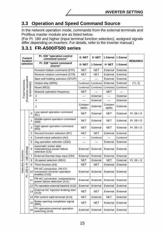
3.3 Operation and Speed Command SourceIn the network operation mode, commands from the external terminals andProfibus master module are as listed below.(For Pr. 180 and higher (input terminal function selection), assigned signalsdiffer depending on inverters. For details, refer to the inverter manual.)3.3.1 FR-A500/F500 series
Control location selection
Pr. 338 "operation control command source" 0: NET 0: NET 1: External 1: External
REMARKSPr. 339 "speed command
source" 0: NET 1: External 0: NET 1: External
Fixe
d fu
nctio
ns
(Fun
ctio
ns e
quiv
alen
t to
term
inal
s)
Forward rotation command (STF) NET NET External ExternalReverse rotation command (STR) NET NET External ExternalStart self-holding selection (STOP) — — External ExternalOutput stop (MRS) Combined Combined External External (*1, 2)Reset (RES) Combined Combined Combined Combined
Network operation frequency NET — NET — 2 — External — External 4 — External — External
1 Compensation External Compen
sation External
Sele
ctiv
e fu
nctio
nsPr
. 180
to P
r. 18
6 se
tting
s
0 Low-speed operation command (RL) NET External NET External Pr. 59 = 0
1 Middle-speed operation command (RM) NET External NET External Pr. 59 = 0
2 High-speed operation command (RH) NET External NET External Pr. 59 = 0
3 Second function selection (RT) NET NET External External4 Current input selection (AU) — Combined — Combined
5 Jog operation selection (JOG) — — External External
6Automatic restart after instantaneous power failure selection (CS)
External External External External
7 External thermal relay input (OH) External External External External8 15-speed selection (REX) NET External NET External Pr. 59 = 09 Third function (X9) NET NET External External
10FR-HC connection, FR-CV connection (inverter operation enable) (X10)
External External External External
11 FR-HC connection, instantaneous power failure detection (X11) External External External External
12 PU operation external interlock (X12) External External External External
13 External DC injection braking start (X13) NET NET External External
14 PID control valid terminal (X14) NET External NET External
15 Brake opening completion signal (BRI) NET NET External External
16 PU operation-external operation switching (X16) External External External External
15

INVERTER SETTING
External : Control by signal from external terminal is only valid.NET : Control from Profibus master module is only valid.Combined : Control from both external terminal and Profibus master module
is valid.— : Control from both external terminal and Profibus master module
is invalid.Compensation : Control by signal from external terminal is only valid if Pr. 28
"multi-speed input compensation" setting is "1".*1 If the FR-HC connection, FR-CV connection (inverter operation enable signal)
(X10) is not assigned when "2" is set in Pr. 30 "regenerative function selection"(when the FR-HC or FR-CV is used) or if the PU operation interlock signal(X12) is not assigned when "7" (when the PU operation interlock function is set)is set in Pr.79 "operation mode selection" , this function is also used by theMRS terminal and therefore operation is only valid for the external terminal,independently of Pr. 338 and Pr. 339 settings.
*2 When the MRS signal is assigned to both network and external control, theoutput stop command is as listed below:
*3 This setting is valid only when the FR-A5AP option is mounted. (The FR-A5APcannot be used with the FR-F500 series.)
*4 Programmed operation is available only with the FR-A500 series.
Sele
ctiv
e fu
nctio
nsPr
. 180
to P
r. 18
6 se
tting
s 17Load pattern selection-forward/reverse rotation boost switching (X17)
NET NET External External
18 Magnetic flux-V/F switching (X18) NET NET External External
19 Load torque high-speed frequency (X19) NET NET External External
20S-pattern acceleration/deceleration C selection terminal (X20) *3
NET NET External External
22 Orientation command (X22) *3 NET NET External External23 Pre-excitation (LX) *3 NET NET External External
RH, RM, RL, RT selective functions
Remote setting (RH, RM, RL) NET External NET External Pr. 59 = 1, 2
Programmed operation group selection (RH, RM, RL) *4 — — — —
Pr. 79 = 5 Network
operation is disabled
Stop-on-contact selection 0 (RL) *4 NET External NET External Pr. 270 = 1, 3Stop-on-contact selection 1 (RT) *4 NET NET External External
Control location selection
Pr. 338 "operation control command source" 0: NET 0: NET 1: External 1: External
REMARKSPr. 339 "speed command
source" 0: NET 1: External 0: NET 1: External
Network External Output Stop CommandPr. 17 = 0 Pr. 17 = 2
ON ON Output stopped Output not stoppedON OFF Output stopped Output stoppedOFF ON Output stopped Output stoppedOFF OFF Output not stopped Output stopped
16

INVERTER SETTING
3.3.2 FR-V500 series
External : Control by signal from external terminal is only valid.NET : Control from Profibus master module is only valid.Combined : Control from both external terminal and Profibus master module is
valid.— : Control from both external terminal and Profibus master module is
invalid.Compensation : Control by signal from external terminal is only valid if Pr. 28 "multi-
speed input compensation" setting is 1.
Control location selection
Pr. 338 "operation control command source" 0: NET 0: NET 1: External 1: External
REMARKSPr. 339 "speed command source" 0: NET 1: External 0: NET 1: External
Fixe
d fu
nctio
ns
(Fun
ctio
ns e
quiv
alen
t to
term
inal
s)
Forward rotation command (STF) NET NET External ExternalReverse rotation command (STR) NET NET External ExternalReset (RES) Combined Combined Combined CombinedExternal thermal relay (OH) External External External ExternalComputer link operation speed NET — NET —2 — External — External
1Speed setting auxiliary Compen
sation External Compensation External
Magnetic flux command/regeneration torque restriction External External External External
3 — External — External
Sele
ctive
func
tions
Pr. 1
80 to
Pr.
183,
Pr.
187
settin
gs *1
0 Low-speed operation command, Remote setting (setting clear) (RL) NET External NET External
Pr. 59 ≠ 0: Remote setting
1 Middle-speed operation command, Remote setting (deceleration) (RM) NET External NET External
2 High-speed operation command, Remote setting (acceleration) (RH) NET External NET External
3 Second function selection (RT) NET NET External External
5 Jog operation selection (JOG) — — External External
8 15-speed selection (REX) NET External NET External
9 Third function (X9) NET NET External External
10FR-HC connection, FR-CV connection (inverter operation enable) (X10)
External External External External
11 FR-HC connection (instantaneous power failure detection) (X11) External External External External
12 PU operation external interlock (X12) External External External External14 PID control enable terminal (X14) NET External NET External
15 Brake sequence opening completion signal (BRI) NET NET External External
16 PU-external operation switchover (X16) External External External External
20 S-pattern acceleration/deceleration C switchover (X20) NET NET External External
22 Orientation command(X22) NET NET External External23 Pre-excitation/servo ON (LX) NET NET External External24 Output stop (MRS) Combined Combined External External *225 Start self-holding selection (STOP) — — External External26 Control mode changing (MC) NET NET External External27 Torque restriction selection (TL) NET NET External External42 Torque bias selection 1 (X42) NET NET External External43 Torque bias selection 2 (X43) NET NET External External
44 P control selection (P/PI control switchover) (X44) NET NET External External
17

INVERTER SETTING
*1 For details of Pr. 180 to Pr. 183, Pr. 187 (input terminal function selection), referto the inverter manual.
*2 When the MRS signal is assigned for both network and external control, theoutput stop command is as indicated in the following table.
Network ExternalOutput Stop Command
Pr.17="0" Pr.17="2"ON ON Output stopped Output not stoppedON OFF Output stopped Output stoppedOFF ON Output stopped Output stoppedOFF OFF Output not stopped Output stopped
18

INVERTER SETTING
3.4 Operation at Communication Error Occurrence 3.4.1 Operation selection at communication error
occurrence (For the FR-A500/V500 series only)You can select operations at error occurrences by setting Pr. 500 to Pr.502 under network operation.
• Parameter setting1) Pr. 500 "communication error recognition waiting time"
You can set the waiting time from when a communication line faultoccurs until it is recognized as a communication error.
If the communication line fault still persists after the time set in Pr. 500 has elapsed, it is recognized as a communication error.When the fault is restored to normal communication within the set time, it is not regarded as a communication error and operation continues.
REMARKSFor the FR-A500, Pr. 500 to Pr. 502 are available with an upgraded inverter. Refer to the inverter manual for the availability of the parameters.
Parameter Number Setting Range Minimum Setting Increments Factory Setting
500 0 to 999.8s 0.1s 0
Recognition
Normal Abnormal
Time set in Pr. 500
Communication line status
Communication error (E. OP3)
19

INVERTER SETTING
2) Pr. 501 "communication error occurrence count display"The cumulative number of communication error occurrences can beindicated. Write 0 to erase this cumulative count.
At the point of communication line fault occurrence, Pr. 501 "communication error occurrence count display" is incremented by 1.
Parameter Number Setting Range Minimum Setting Increments Factory Setting
501 0 1 0
CAUTIONThe communication error occurrence count is stored into RAM temporarily. Since this data is stored in E2PROM at one-hour intervals, performing power-on reset or inverter reset may cause the Pr. 501 data to be the value stored in E2PROM the last time depending on the reset timing.
Normal AbnormalCount timing depending oncommunication line status
Incremented by 1
Normal Abnormal
Incremented by 1
20

INVERTER SETTING
3) Pr. 502 "communication error-time stop mode selection"You can select the inverter operation if a communication line fault or afault of the option unit itself occurs.
About setting• At Fault Occurrence
* If the fault status returns to the normal communication status within the time set in Pr. 500 , communication line fault (E.OP3) does not occur.
• At Fault Recognition after Elapse of Pr. 500 Time
• At Fault Removal
Parameter Number Setting Range Minimum Setting Increments Factory Setting
502 0, 1, 2 1 0
Fault Pr. 502 Setting Operation Indication Alarm output
Communication line
0Continued* Normal indication* Not provided*1
2
Option itself 0 Coast to stop E. 3 lit Provided
1, 2 Decelerated to stop E. 3 lit after stop Provided after
stop
Fault Pr. 502 Setting Operation Indication Alarm output
Communication line
0 Coast to stop E.OP3 lit Provided
1 Deceleratedto stop
E.OP3 lit after stop
Provided after stop
2 Decelerated to stop
E.OP3 lit after stop Not provided
Option itself 0 Coast to stop E. 3 lit Provided
1, 2 Decelerated to stop
E. 3 lit after stop
Provided after stop
Fault Pr. 502 Setting Operation Indication Alarm output
Communication line
0Kept stopped E.OP3 kept lit Kept provided
12 Restart Normal indication Not provided
Option itself 0
Kept stopped E. 3 kept lit Kept provided1, 2
21

INVERTER SETTING
CAUTION1. A communication line fault [E.OP3 (alarm data: HA3)] is a fault
that occurs on the communication line, and a fault of the option unit itself [E. 3 (alarm data: HF3)] is a communication circuit fault in the option.
2. The alarm output is the ABC contact output or alarm bit output.3. When the Pr. 502 setting is "1" or "2", the deceleration time is
the ordinary deceleration time setting (e.g. Pr. 8, Pr. 44, Pr. 45).4. The acceleration time at a restart is the ordinary acceleration
time setting (e.g. Pr. 7, Pr. 44).5. When the Pr. 502 setting is "2", the operation/speed command at
a restart is the one given before the fault occurrence.6. When the setting was made to provide an alarm output, the fault
definition is stored into the alarm history. (The fault definition is written to the alarm history when an alarm output is provided.)When no alarm output is provided, the fault definition overwrites the alarm indication of the alarm history temporarily, but is not stored. After the fault is removed, the alarm indication is reset and returns to the ordinary monitor, and the alarm history returns to the preceding alarm indication.
7. When a communication line fault occurs at the Pr. 502 setting of "2", removing the fault during deceleration causes acceleration to restart at that point. (Acceleration is not restarted if the fault is that of the option unit itself.)
22

INVERTER SETTING
3.4.2 Alarm and measures(1) The inverter operates as follows at alarm occurrences
(2) Measures at alarm occurrences
When alarms other than the above are displayed, refer to the invertermanual and remove the cause of the alarm.
Fault Location Status
Operation Mode
PU operation External operation
Network operation
Inverter alarm
Inverter operation Inverter trip Inverter trip Inverter tripData communication Continued Continued Continued
Commu-nication line alarm
Inverter operation Continued Continued
Inverter trip (Depends on the Pr. 502
setting)Data communication Stop Stop Stop
Option itself
Communi-cation option con-nection fault
Inverter operation
Inverter trip (Depends on the Pr. 502
setting)
Inverter trip (Depends on the Pr. 502
setting)
Inverter trip (Depends on the Pr. 502
setting)Data commu-nication
Continued Continued Continued
FR-A5NPA alarm
Inverter operation Continued Continued
Inverter trip (Depends on the Pr. 502
setting)Data commu-nication
Stop Stop Stop
Alarm Indication Alarm Definition Measures
E. OP3 Communication line alarm
Check the LED states of the option unit (FR-A5NPA) and remove the cause of the alarm. (Refer to page 2 for the LED indication status.)Check the Profibus master module.
E. 3 Option alarm
Check the connection between the inverter and option unit (FR-A5NPA) for poor contact, etc. and remove the cause of the alarm.
23

INVERTER SETTING
3.4.3 Inverter resetWhich resetting method is allowed or not allowed in each operation modeis described below.
3.5 InstructionsFor the FR-A500/F500 series, use the factory-set values when using Pr.37 "speed display" and Pr. 144 "speed setting switchover". The invertermay not function correctly if the setting was changed.
Resetting MethodOperation Mode
Network operation
External operation
PUoperation
Profibus master module
Inverter reset• Inverter reset can be made
any time.Allowed Disallowed Disallowed
Error reset at inverter fault• Reset can be made only
when the protective function of the inverter is activated.
Allowed Allowed Allowed
Connect terminals RES-SD Allowed Allowed AllowedSwitch off inverter power Allowed Allowed Allowed
CAUTION1. When a communication line fault has occurred, reset cannot be
made from the Profibus master module.2. The inverter is set to the external operation mode if it has been
reset in the network operation mode.To resume the network operation, the inverter must be switched to the network operation again. (When "1" or "2" is set in Pr. 340 "link startup mode selection", switching is not needed. Refer to page 12.)
3. Communication stops for about 1 s during inverter reset.
24

4. FUNCTION OVERVIEW
4.1 Function OverviewThe following table lists the functions that can be controlled from theProfibus master module.
*1 At a communication error, reset cannot be made from the master module.(For inverter reset, refer to the inverter manual.)
*2 As set in Pr. 75 "PU stop selection".*3 As set in Pr. 77 "parameter write disable selection".
For parameters write-enabled during operation, refer to the inverter manual.*4 As set in Pr. 338 and Pr. 339. (Refer to pages 15, 17.)
Control Location Item
Operation ModePU
operationExternal
operationNetwork
operation
Profibus
Operation command/Output frequency setting Disallowed Disallowed Allowed
Monitor Allowed Allowed Allowed
Parameter write Disallowed*3
Disallowed*3 Allowed *3
Parameter read Allowed Allowed AllowedInverter reset Disallowed Disallowed Allowed *1Error reset at inverter fault Allowed *1 Allowed *1 Allowed *1Stop command (*2) Disallowed Disallowed Allowed
Control circuit terminal
Inverter reset terminal Allowed Allowed AllowedOperation command/Output frequency setting Disallowed Allowed Allowed *4
CAUTIONThe external operation mode is selected when the inverter is reset from the master module in the network operation mode.Setting "1" or "2" in Pr. 340 selects the network operation mode.
25

FUNCTION OVERVIEW
4.1.1 Input from master module to inverter(1) Operation command
The following items can be output any time from the master module to the inverter as operation commands. (Refer to pages 39, 46)
*1 These are factory-set signals. Input signals can be changed by inputterminal function selection (Pr. 180 and higher). Note that some signals donot accept a command from the master module according to the settings.Refer to page 15 for details. Signals to be assigned to input terminalfunction selection (Pr. 180 and higher) differ according to the inverters. Fordetails, refer to the inverter manual.
*2 Signals can be assigned using input terminal function selection (Pr. 400 toPr. 402). Refer to page 8. (when the FR-A5NPA is connected)
(2) Set frequency/set speedWrite a setting change from the master module to the inverter. (Refer to pages 38, 45.)
(3) Parameter writeYou can write a function from the master module. Note that writing a function during inverter operation will result in a write mode error. (Refer to pages 35, 42.) Refer to the inverter manual for parameter details.
(4) Inverter resetYou can reset the inverter or reset an inverter error. (Refer to pages 37, 44, 50, 60.)
FR-A500/F500 series FR-V500 series
Terminal Operation Command (Signal) Terminal Operation Command
(Signal)STF Forward rotation command
(STF) STF Forward rotation command (STF)
STR Reverse rotation command (STR) STR Reverse rotation command
(STR)
RH High speed operation command (RH) *1 DI1 Low speed operation
command (RL) *1
RM Middle speed operation command (RM) *1 DI2 Middle speed operation
command (RM) *1
RL Low speed operation command (RL) *1 DI3 High speed operation
command (RH) *1
JOG Jog operation selection (JOG) *1 DI4 Second function selection
(RT) *1
RT Second function selection (RT) *1 DI11 — *2
AU Current input selection (AU) *1 DI12 — *2
CS Instantaneous power failure restart selection (CS) *1 DI13 — *2
MRS Output stop (MRS) MRS Output stop (MRS)
26

FUNCTION OVERVIEW
4.1.2 Output from inverter to master module(1) Monitor function
You can monitor the following items from the master module.1) Running frequency :0.01Hz increments (FR-A500/F500 series)
(Refer to page 38.)Running speed : 1r/min increments (FR-V500 series) (Refer to
page 45.)2) Alarm definition : Refer to page 51 for the FR-A500/F500 series
and page 61 for the FR-V500 series.3) Special monitoring: Monitor data set by the real time monitor (P1.1
to P1.37). Refer to page 48 for the FR-A500/F500 series and page 57 for the FR-V500 series.
4) Inverter statusInverter output signal can be monitored by the PNU. (Refer to pages 38, 45.)
(2) Parameter readYou can read a function to the master module. (Refer to pages 35, 42.)Refer to the inverter manual for parameter details.
FR-A500/F500 series FR-V500 seriesOutput Definition (Signal) Output Definition (Signal)
Inverter running (RUN) Inverter running (RUN)Forward running Forward runningReverse running Reverse runningUp to frequency (SU) Up to speed (SU) Overload alarm (OL) Overload alarm (OL)Instantaneous power failure or under voltage (IPF)
Instantaneous power failure or under voltage (IPF)
Frequency detection (FU) Speed detection (FB)Alarm output (ABC) Alarm output (ABC)
27

5. Profibus PROFILES
5.1 Profibus Device DataMEAU0865A. GSD is a GSD file designed to recognize the features andfunctions of the Profibus DP devices of the FR-A5NPA.You can obtain it from us. Please contact your sales representative. When editing this file, use a text editor.For installation instruction, refer to the instruction manual of the Profibus-DP Configuration Software.
<MEAU0865A.GSD>Parameter Value Description*1
#Profibus_DP File headerGSD_Revision 1 ID version of GSD file
Vendor_Name "Mitsubishi Electric" Manufacturer’s name*2
Model_Name "FR-A5NPA" Product nameRevision "Revision 2.00" Product version
Ident_Number 0865AHDevice number obtained from Profibus Nutzer Organization
Protocol_Ident 0 Profibus-DP is 0.Station_Type 0 DP slave is 0.
FMS_Supp 0 FMS (Field-Bus Message Specifications) not supported.
Hardware_Release "Series A" Hardware versionSoftware Release "Revision 2.00" Software version9.6_supp 1 Communication speed 9600bps support19.2_supp 1 Communication speed 19.2Kbps support93.75_supp 1 Communication speed 93.75Kbps support187.5_supp 1 Communication speed 187.5Kbps support500_supp 1 Communication speed 500Kbps support1.5M_supp 1 Communication speed 1.5Mbps support3.0M_supp 1 Communication speed 3.0Mbps support6.0M_supp 1 Communication speed 6.0Mbps support12.0M_supp 1 Communication speed 12.0Mbps support
MaxTsdr_9.6 60 Longest time 60 bit times at 9600bps communication speed
MaxTsdr_19.2 60 Longest time 60 bit times at 19.2Kbps communication speed
MaxTsdr_93.75 60 Longest time 60 bit times at 93.75Kbps communication speed
MaxTsdr_187.5 60 Longest time 60 bit times at 187.5Kbps communication speed
MaxTsdr_500 100 Longest time 100 bit times at 500Kbps communication speed
28

Profibus PROFILES
MaxTsdr_1.5M 150 Longest time 150 bit times at 1.5MKbps communication speed
MaxTsdr_3.0M 250 Longest time 250 bit times at 3.0Mbps communication speed
MaxTsdr_6.0M 450 Longest time 450 bit times at 6.0Mbps communication speed
MaxTsdr_12.0M 800 Longest time 800 bit times at 12.0Mbps communication speed
Redundancy 0 Redundancy not supported.
Repeater_Ctrl_Sig 2 Installed as TTL level via RTS signal from module.
24V_Pins 0 24V power supply for maintenance device connection is not used.
Freeze_Mode_supp 1 Freeze mode supported.Sync_Mode_supp 1 Synchronous mode supported.Auto_Baud_supp 1 Automatic baud rate detection supportSet_Slave_Add_supp 0 Slave address is not set.Min_Slave_Intervall 1 100µs interval between 2 polling cyclesModular_Station 1 Modular device specified.Max_Module 1 Maximum number of modules: 1Max_Input_Len 28 Input data: Maximum 28 bytesMax_output_Len 28 Output data: Maximum 28 bytes
Max_Data_Len 56 Input and output data: Maximum 28 + 28 = 56 bytes
Fail_Safe 0 Failsafe not supported
Max_Diag_Data_Len 6 Diagnostic data of 6 bytes secured (no external diagnosis)
Slave_Family 1 Drives defined as function class (Main Family)
PrmText 1 Text selection 1 registration
Text(0) "No byte swapping" If Bit 0 = 0, "No byte swapping"
Text(1) "Byte swapping" If Bit 0 = 1, "Byte swapping"
EndPrmText
ExtUserPrmData 1 "Byte swapping"
Byte swapping selection 1 registration on text base
Bit(0) 0 0-1 Bit 0 = default 0, range 0 to 1Prm_Text_Ref 1 Text selection 1 is used.EndExtUserPrmDataMax_User_Prm_Data_Len 2 User parameter of 2 bytes secured
Ext_User_Prm_Data_Const(0) 01H Initial value of user parameter's first byte
Parameter Value Description*1
29

Profibus PROFILES
*1 Description is not included in the ASCII file itself.*2 Use "Mitsubishi" if the maximum number of characters of the vendor-
name of the master used is 10.
5.2 Slave User ParameterBy changing the slave user parameter value, you can use the byteswapping function (byte inversion function).Setting "1" at Address 1H (Bit 0) makes the byte swapping function valid.Since "-" is an unused bit, set "0".
Ext_User_Prm_Data_Const(1) 00H
Initial value of user parameter's second byte
Ext_User_Prm_Data_Ref(1) 1 Byte swapping selection 1 is used on text
base in user parameter's second byte.
Module "PPO type 1" F3H, F1H
PPO type 1 selection
EndModule
Module "PPO type 2" F3H, F5H
PPO type 2 selection
EndModule
Module "PPO type 3" F1H
PPO type 3 selection
EndModule
Module "PPO type 4" F5H
PPO type 4 selection
EndModule
Module "PPO type 5" F3H, F9H PPO type 5 selection
EndModule
Address Function0H For manufacturer’s setting (Value should be "1".)
1H
15Bit
14Bit
13Bit
12Bit
11Bit
10Bit
9Bit
8Bit
- - - - - - - -7
Bit6
Bit5
Bit4
Bit3
Bit2
Bit1
Bit0
Bit
- - - - - - -
0:Byte swapping invalid
1:Byte swapping valid
Parameter Value Description*1
30

Profibus PROFILES
5.3 Profibus ProfilesThe option unit operates as a "slave of the Profibus DP master" or a"controller equivalent to Profibus DP master class 1 on an RS-485network".The Profibus profile (data buffer) can be selected from among five differenttypes, "PPO type 1" to "PPO type 5". Change the Module type in the slavemodule setting. For details, refer to the instruction manual of the NetworkMaster Configuration Software.
5.3.1 ID definitions
* Command request :Message from master to slaveCommand response :Message from slave to master
ID Description
PKW
PKE PNU number (PNU) and task or response Id (AK)IND Sub-Index number and reserved area for extension
PWE Set 0 since high bits (Bits 16 to 31) are not used.Low bits (Bits 0 to 15): Parameter value
PZD
STW/ZSW
STW :Control word (command request)ZSW :Status word (command response)
HSW/HIW
HSW :Set frequency/set speed (command request)HIW :Running frequency/running speed (command response)
ECW/ESW
ECW :Extended control word (command request)ESW :Extended status word (command response)
Reserved Reserved area for extension
1 word
PKE IND PWE STW/ZSW
HSW/HIW
PPOtype 1
Input data: 6 wordsOutput data: 6 words
PKE IND PWE STW/ZSW
HSW/HIW
ECW/ESW
Reser-ved
Reser-ved
Reser-ved
PPOtype 2
Input data: 10 wordsOutput data: 10 words
STW/ZSW
HSW/HIW
PPOtype 3
Input data: 2 wordsOutput data: 2 words
STW/ZSW
HSW/HIW
ECW/ESW
Reser-ved
Reser-ved
Reser-ved
PPOtype 4
Input data: 6 wordsOutput data: 6 words
PKE IND PWE STW/ZSW
HSW/HIW
ECW/ESW
Reser-ved
Reser-ved
Reser-ved
Reser-ved
Reser-ved
Reser-ved
Reser-ved
PPOtype 5
Input data: 14 wordsOutput data: 14 words
PKW PZD
31

Profibus PROFILES
5.3.2 Buffer memory mapThe following shows the buffer memory map of the PPO type 1 to PPOtype 5 Profibus profiles.
5.3.3 Points to noteOnly when the contents of the command request (request for changing theinverter setting: PKW, HSW, STW/ECW) from the master changed, theinverter processes the request. If the contents of the command requestare identical with those of the last request, the inverter does not processthe request. (The received request is cleared.)
For instance, while the master keeps sending the "network operationmode enabled" command, changing the mode to the PU operation modewith switchover function does not allow the "network operation modeenabled" command to be executed due to the same contents as thatsent last time. Therefore, the operation mode remains the PU operationmode without changing to the network operation mode. In this case, send another command as "PU operation mode enabled"from the master once, then send the "network operation mode enabled"command again.
PKE IND PWE STW/ZSW
HSW/HIW
PPOtype 1
PKE IND PWE STW/ZSW
HSW/HIW
ECW/ESW
Reser-ved
Reser-ved
Reser-ved
STW/ZSW
HSW/HIW
STW/ZSW
HSW/HIW
ECW/ESW
Reser-ved
Reser-ved
Reser-ved
PKE IND PWE STW/ZSW
HSW/HIW
ECW/ESW
Reser-ved
Reser-ved
Reser-ved
Reser-ved
Reser-ved
Reser-ved
Reser-ved
1Word 2Word 3Word 4Word 5Word 6Word 7Word 8Word 9Word 10Word11Word 12Word13Word14Word
PPOtype 2
PPOtype 3
PPOtype 4
PPOtype 5
32

6. BUFFER MEMORY DETAILS
6.1 FR-A500/F500 SeriesThe following indicates the buffer memory details of the FR-A500/F500series Profibus profiles.
AK PNU (parameter number)PKE
Task SPM Not support
151413121110 9 8 7 6 5 4 3 2 1 0 bit
Sub-IndexIND151413121110 9 8 7 6 5 4 3 2 1 0 bit
reserved
31 30 29 28 27 26 25 24 23 22 21 20 19 18 17 16 bit
PWE (set value)151413121110 9 8 7 6 5 4 3 2 1 0 bit
0 0 0 0 0 0 0 0 0 0 0 0 0 0 0 0PWE
STW
RAM/E2PROM
151413121110 9 8 7 6 5 4 3 2 1 0 bit0 0 1 1 1 1 1 1
MRSRTSTR
STFPZD enable
Not supportFault reset
Not supportOperation enable
Not support
HSW (set frequency)HSW151413121110 9 8 7 6 5 4 3 2 1 0 bit
ECW
RH
151413121110 9 8 7 6 5 4 3 2 1 0 bit0 0
RMJOG
0
CSAU
RL
command count
Master→→→→Slave (command request)
33

BUFFER MEMORY DETAILS
AK PNU (parameter number)PKE
Response SPM Not support
151413121110 9 8 7 6 5 4 3 2 1 0 bit
Sub-IndexIND151413121110 9 8 7 6 5 4 3 2 1 0 bit
reserved
31 30 29 28 27 26 25 24 23 22 21 20 19 18 17 16 bit
PWE (read value)151413121110 9 8 7 6 5 4 3 2 1 0 bit0 0 0 0 0 0 0 0 0 0 0 0 0 0 0 0
PWE
ZSW
Busy
151413121110 9 8 7 6 5 4 3 2 1 0 bit1 0 0 1 1 1 1 1
NET modeREW
FWDRUN
FU
Power on inhibitNot support
FaultNot support
HIW (operation frequency)HIW151413121110 9 8 7 6 5 4 3 2 1 0 bit
ESW
SU
151413121110 9 8 7 6 5 4 3 2 1 0 bit0 0 0 0 0
OL
AlarmNot support
Control request
Slave →→→→ Master (command response)
command count
IPF
34

BUFFER MEMORY DETAILS
FR-A500/F500 seriesName Bit Description
PKW
PKE
PNU 0 to 10 PNU numberSPM 11 Not used (0 is set)
AK 12 to 15
[Command request]0:No task1:Parameter value is requested (read request)2:Parameter value (word) is changed (write
request3 to 5:Not supported6:Parameter value (array) is requested (read
request)7:Parameter value (array word) is changed (write
request)8 to 15:Not supported[Command response]0:No response1:Parameter value (word) is transferred.2 to 3:Not supported4:Parameter value (array word) is transferred.5 to 6:Not supported7:Command execution error (error number is
stored into PWE)8 to 15:Not supported
IND
0 to 7 Reserved area for extension (0 is set)
8 to 15Sub-Index numberAt command request, set this number when AK = 6 or 7.
35

BUFFER MEMORY DETAILS
PKW PWE0 to 15
PNU read value/write valueWhen command response AK = 7 (command execution error), PWE definition is as follows.
16 to 31 Not used (0 is set)
FR-A500/F500 seriesName Bit Description
*1 Error Definition
Error Definition0 Invalid PNU
1 Parameter value unchangeable(This error also occurs when Pr. 77 = 1)
2 Outside setting range3 Invalid Sub-Index number4 No array11 No parameter change right18 Other error (*1)
• Outside AK number range• Write data error• External operation error• Without option error• Instruction code error• With STF error• With STR error• With operation mode specification error• Calibration error (Pr. 900 and later) • Reset disabled error
(per Pr. 75 reset input specification)
36

BUFFER MEMORY DETAILS
PZD STW
- 0 to 2 Not used (1 is set)Control enable 3 0:Inverter output shutoff
1:Inverter output shutoff is cancelled- 4 to 6 Not used (1 is set)
Fault reset 7
[At inverter error]0:No action1:Inverter reset[When inverter is normal]No action
- 8 to 9 Not used (0 is set)
PZD enable 10
0:Command request of PZD is not processed. (*1)1:Command request of PZD is processed.• At power-on or inverter reset, set 1 once.
STF signal 11 0:OFF
1:ON (Forward rotation command)STR
signal 12 0:OFF1:ON (Reverse rotation command)
RT terminal 13
0:RT-OFF1:RT-ONFactory-set to the second function selectionPr. 183 can be used to change the signal. (*2)
MRS signal 14 0:OFF
1:ON (Output shutoff)
RAM/E2PROM
15
0:Set frequency (HSW) is written to RAM (Power-on reset returns the changed set frequency to the setting before it was written to RAM.).
1:Set frequency (HSW) is written to E2PROM.*1 PZD enable and command count request can be executed.*2 Refer to the inverter manual for details of the input terminal function selection
(Pr. 180 to Pr. 186).
FR-A500/F500 seriesName Bit Description
37

BUFFER MEMORY DETAILS
PZDZSW
- 0 to 2 Not used (1 is returned)Fault
(Alarm signal)
3 0:Inverter normal1:Inverter alarm occurrence
- 4 to 5 Not used (1 is returned)Power-
on inhibit 6 0 is returned
Alarm 7 0:Command execution normal1:Command execution error
- 8 Not used (0 is returned)Control request 9 1 is returned
FU signal 10
0:OFF1:ON (Output frequency being detected)Refer to Pr. 42 and Pr. 43 in the inverter manual.
RUN signal 11 0:OFF
1:ON (Inverter running)
FWD 12
0:Other than forward operation being performed (at a stop, reverse rotation operation being performed)1:Forward rotation operation being performed
REW 13
0:Other than reverse operation being performed(at a stop, forward rotation operation being performed)1:Reverse rotation operation being performed
Operation mode 14 0:Other than network operation mode
1:Network operation mode
BUSY 15
0:Ready status1:Busy statusIf it takes time to perform slave side processing, slave side busy status is announced since reply to master will be delayed.In busy status, other response data are unfixed values. When slave side is busy, request from master is invalid. Therefore, the same request must be sent again. During busy status, 0 is returned for all Bits except for Bit 15.
HSW 0 to 15 Set frequency (0.01 Hz increments)HIW 0 to 15 Running frequency (0.01 Hz increments)
FR-A500/F500 seriesName Bit Description
38

BUFFER MEMORY DETAILS
PZD
ECW
RH terminal 0
0:RH-OFF1:RH-ONFactory-set to high-speed operation command Pr. 182 can be used to change the signal. (*1)
RM terminal 1
0:RM-OFF1:RM-ONFactory-set to middle-speed operation command Pr. 181 can be used to change the signal. (*1)
RL terminal 2
0:RL-OFF1:RL-ONFactory-set to low-speed operation command Pr. 180 can be used to change the signal. (*1)
JOG terminal 3
0:JOG-OFF1:JOG-ONFactory-set to jog operation selection Pr. 185 can be used to change the signal. (*1)
AU terminal 4
0:AU-OFF1:AU-ONFactory-set to current input selection Pr. 184 can be used to change the signal. (*1)
CS terminal 5
0:CS-OFF1:CS-ONFactory-set to automatic restart afterinstantaneous power failure selection Pr. 186 can be used to change the signal. (*1)
- 6, 7 Not used (0 is set)Command
count 8 to 15 Used by the master to recognize the command response
ESW
SU signal 0 0:OFF
1:ON (Up to frequency)OL
signal 1 0:OFF1:ON (Overload alarm)
IPF signal 2
0:OFF1:ON (Instantaneous power failure or undervoltage)
- 3 to 7 Not used (0 is set)Command
count 8 to 15 Echo back of the command request
Reserved 0 to 15 Not used (0 is set, 0 is returned)*1 Refer to the inverter manual for details of the input terminal function selection
(Pr. 180 to Pr. 186).
FR-A500/F500 seriesName Bit Description
39

BUFFER MEMORY DETAILS
6.2 FR-V500 SeriesThe following indicates the buffer memory details of the FR-V500 seriesProfibus profiles.
AK PNU (parameter number)PKE
Task SPM Not support
151413121110 9 8 7 6 5 4 3 2 1 0 bit
Sub-IndexIND151413121110 9 8 7 6 5 4 3 2 1 0 bit
reserved
31 30 29 28 27 26 25 24 23 22 21 20 19 18 17 16 bit
PWE (set value)151413121110 9 8 7 6 5 4 3 2 1 0 bit
0 0 0 0 0 0 0 0 0 0 0 0 0 0 0 0PWE
STW
RAM/E2PROM
151413121110 9 8 7 6 5 4 3 2 1 0 bit0 0 1 1 1 1 1 1
MRSDI11
STRSTF
PZD enableNot support
Fault resetNot support
Operation enableNot support
HSW (set speed)HSW151413121110 9 8 7 6 5 4 3 2 1 0 bit
ECW
DI1
151413121110 9 8 7 6 5 4 3 2 1 0 bit0 0
DI2DI4
DI13DI12
DI3
command count
Master→→→→Slave (command request)
40

BUFFER MEMORY DETAILS
AK PNU (parameter number)PKE
Response SPM Not support
151413121110 9 8 7 6 5 4 3 2 1 0 bit
Sub-IndexIND151413121110 9 8 7 6 5 4 3 2 1 0 bit
reserved
31 30 29 28 27 26 25 24 23 22 21 20 19 18 17 16 bit
PWE (read value)151413121110 9 8 7 6 5 4 3 2 1 0 bit0 0 0 0 0 0 0 0 0 0 0 0 0 0 0 0
PWE
ZSW
Busy
151413121110 9 8 7 6 5 4 3 2 1 0 bit1 0 0 1 1 1 1 1
NET modeREW
FWDRUN
FB
Power on inhibitNot support
FaultNot support
HIW (operation speed)HIW151413121110 9 8 7 6 5 4 3 2 1 0 bit
ESW
SU
151413121110 9 8 7 6 5 4 3 2 1 0 bit0 0 0 0 0
OL
AlarmNot support
Control request
Slave →→→→ Master (command response)
command count
IPF
41

BUFFER MEMORY DETAILS
FR-V500 seriesName Bit Description
PKW
PKE
PNU 0 to 10 PNU numberSPM 11 Not used (0 is set)
AK 12 to 15
[Command request]0:No task1:Parameter value is requested (read request)2:Parameter value (word) is changed (write
request)3 to 5:Not supported6:Parameter value (array) is requested (read
request)7:Parameter value (array word) is changed (write
request)8 to 15:Not supported[Command response]0:No response1:Parameter value (word) is transferred.2 to 3:Not supported4:Parameter value (array word) is transferred.5 to 6:Not supported7:Command execution error (error number is
stored into PWE)8 to 15:Not supported
IND
0 to 7 Reserved area for extension (0 is set)
8 to 15Sub-Index numberAt command request, set this number when AK = 6 or 7.
42

BUFFER MEMORY DETAILS
PKW PWE0 to 15
PNU read value/write valueWhen command response AK = 7 (command execution error), PWE definition is as follows.
16 to 31 Not used (0 is set)
FR-V500 seriesName Bit Description
*1 Error Definition
Error Definition0 Invalid PNU
1 Parameter value unchangeable(This error also occurs when Pr. 77 = 1)
2 Outside setting range3 Invalid Sub-Index number4 No array11 No parameter change right18 Other error (*1)
• Outside AK number range• Write data error• External operation error• Without option error• Instruction code error• With STF error• With STR error• With operation mode specification error• Calibration error (Pr. 900 and later) • Reset disabled error
(per Pr. 75 reset input specification)
43

BUFFER MEMORY DETAILS
PZD STW
- 0 to 2 Not used (1 is set)Control enable 3 0:Inverter output shutoff
1:Inverter output shutoff is cancelled- 4 to 6 Not used (1 is set)
Fault reset 7
[At inverter error]0:No action1:Inverter reset[When inverter is normal]No action
- 8 to 9 Not used (0 is set)
PZD enable 10
0:Command request of PZD is not processed. (*1)1:Command request of PZD is processed.• At power-on or inverter reset, set 1 once.
STF signal 11 0:OFF
1:ON (Forward rotation command)
STR signal 12
0:STR-OFF1:STR-ONFactory-set to reverse rotation commandPr. 187 can be used to change the signal. (*2)
DI11 terminal 13
0:DI11 terminal function-OFF1:DI11 terminal function-ONPr. 400 can be used to select the signal. (*3)
MRS signal 14 0:OFF
1:ON (Output shutoff)
RAM/E2PROM
15
0:Set speed (HSW) is written to RAM (Power-on reset returns the set speed to the setting before it was written to RAM.).
1:Set speed (HSW) is written to E2PROM.*1 PZD enable and command count request can be executed.*2 Refer to the inverter manual for details of the input terminal function selection
(Pr. 180 to Pr. 183, Pr. 187).*3 Refer to the inverter manual for the signal types.
FR-V500 seriesName Bit Description
44

BUFFER MEMORY DETAILS
PZDZSW
- 0 to 2 Not used (1 is returned)Fault
(Alarm signal)
3 0:Inverter normal1:Inverter alarm occurrence
- 4 to 5 Not used (1 is returned)Power-
on inhibit 6 0 is returned
Alarm 7 0:Command execution normal1:Command execution error
- 8 Not used (0 is returned)Control request 9 1 is returned
FB signal 100:OFF1:ON (Output speed being detected) (Refer to Pr. 42, 43 in the invert manual)
RUN signal 11 0:OFF
1:ON (Inverter running)
FWD 12
0:Other than forward rotation operation being performed (at a stop, reverse rotation operation being performed)1:Forward rotation operation being performed
REW 13
0:Other than reverse rotation operation being performed (at a stop, forward rotation operation being performed)1:Reverse rotation operation being performed
Operation mode 14 0:Other thatn network operation mode
1:Network operation mode
BUSY 15
0:Ready status1:Busy statusIf it takes time to perform slave side processing, slave side busy status is announced since reply to master will be delayed.In busy status, other response data are unfixed values. When slave side is busy, request from master is invalid. Therefore, the same request must be sent again. During busy status, 0 is returned for all Bits except for Bit 15.
HSW 0 to 15 Set speed (1 r/min increments)HIW 0 to 15 Running speed (1 r/min increments)
FR-V500 seriesName Bit Description
45

BUFFER MEMORY DETAILS
PZD
ECW
DI1 terminal 0
0:RL-OFF1:RL-ONFactory-set to low-speed operation command Pr. 180 can be used to change the signal. (*1)
DI2 terminal 1
0:RM-OFF1:RM-ONFactory-set to middle-speed operation commandPr. 181 can be used to change the signal. (*1)
DI3terminal 2
0:RH-OFF1:RH-ONFactory-set to high-speed operation commandPr. 182 can be used to change the signal. (*1)
DI4 terminal 3
0:RT-OFF1:RT-ONFactory-set to second function selection Pr. 183 can be used to change the signal. (*1)
DI12 terminal 4
0:DI12 terminal function-OFF1:DI12 terminal function-ONPr. 401 can be used to change the signal. (*1)
DI13 terminal 5
0:DI13 terminal function-OFF1:DI13 terminal function-ONPr. 402 can be used to change the signal. (*2)
- 6, 7 Not used (0 is set)Command
count 8 to 15 Used by the master to recognize the command response
ESW
SU signal 0 0:OFF
1:ON (Up to speed)OL
signal 1 0:OFF1:ON (Overload alarm)
IPF signal 2 0:OFF
1:ON (Instantaneous power failure/undervoltage )- 3 to 7 Not used (0 is set)
Command count 8 to 15 Echo back of the command request
Reserved 0 to 15 Not used (0 is set, 0 is returned)*1 Refer to the inverter manual for details of the input terminal function selection
(Pr. 180 to Pr. 183, Pr. 187).*2 Refer to the inverter manual for the signal types.
FR-V500 seriesName Bit Description
46
7. PARAMETER DEFINITIONS - A500/F500 SERIES
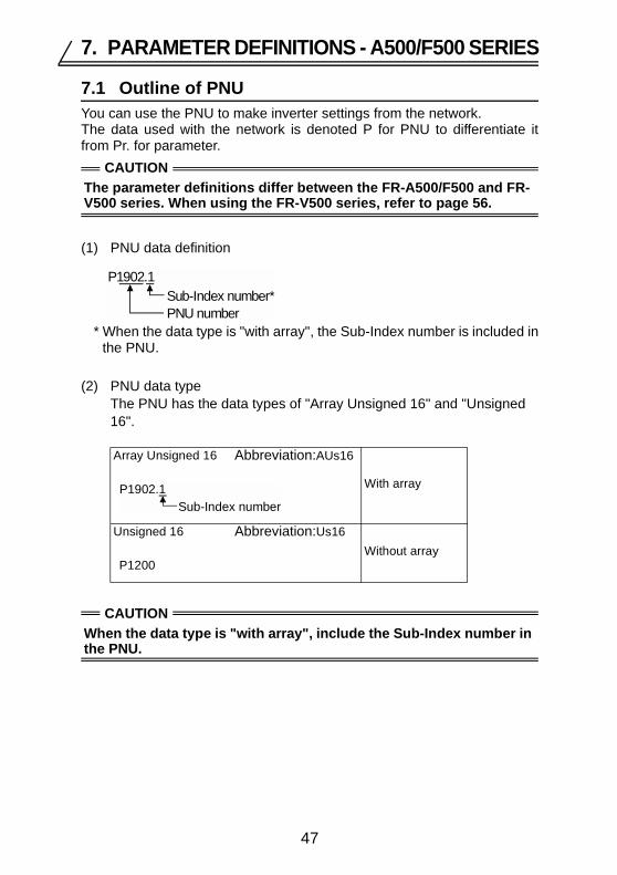
7.1 Outline of PNUYou can use the PNU to make inverter settings from the network.The data used with the network is denoted P for PNU to differentiate itfrom Pr. for parameter.
(1) PNU data definition
* When the data type is "with array", the Sub-Index number is included inthe PNU.
(2) PNU data typeThe PNU has the data types of "Array Unsigned 16" and "Unsigned 16".
CAUTIONThe parameter definitions differ between the FR-A500/F500 and FR-V500 series. When using the FR-V500 series, refer to page 56.
Array Unsigned 16 Abbreviation:AUs16
With array
Unsigned 16 Abbreviation:Us16Without array
CAUTIONWhen the data type is "with array", include the Sub-Index number in the PNU.
P1902.1Sub-Index number*PNU number
P1902.1Sub-Index number
P1200
47

PARAMETER DEFINITIONS - A500/F500 SERIES
7.2 Profibus PNU7.2.1 Real-time monitorThe following items can be monitored from the master.
* Can be monitored only when the FR-A5AP is fitted.
PNU Item Unit Data Type
P1.1 Output frequency 0.01Hz AUs16P1.2 Output current 0.01A AUs16P1.3 Output voltage 0.1V AUs16P1.5 Frequency setting 0.01Hz AUs16P1.6 Running speed 1r/min AUs16P1.7 Motor torque 0.1% AUs16P1.8 Converter output voltage 0.1V AUs16P1.9 Regenerative brake duty 0.1% AUs16
P1.10 Electronic overcurrent protection load factor 0.1% AUs16P1.11 Output current peak value 0.01A AUs16P1.12 Converter output voltage peak value 0.1V AUs16P1.13 Input power 0.01kW AUs16P1.14 Output power 0.01kW AUs16P1.15 Input terminal status (refer to page 49 (1)) - AUs16P1.16 Output terminal status (refer to page 49 (2)) - AUs16P1.17 Load meter 0.1% AUs16P1.18 Motor excitation current 0.01A AUs16P1.19 Position pulse* - AUs16P1.20 Cumulative energization time 1h AUs16P1.22 Orientation status* - AUs16P1.23 Actual operation time 1h AUs16P1.24 Motor load factor 0.1% AUs16P1.25 Cumulative power 1kWh AUs16
48

PARAMETER DEFINITIONS - A500/F500 SERIES
(1) External input terminal status PWE bitmap
* Pr. 180 to 186 can be used to assign the terminal functions. Refer to the inverter manual for details of the terminal functions.
(2) External output terminal status PWE bitmap
* Pr. 190 to 195 can be used to assign the terminal functions. Refer to the inverter manual for details of the terminal functions.
STFSTRAU*RT*RL*RM*RH*JOG*MRSSTOPRESCS*0 0 00Terminal name
Not used (system reserved)
Bit 1415 13 12 11 10 9 8 7 6 012345
Terminal name
Not used (system reserved)
Bit
RUN*SU*IPF*OL*FU*ABC*0 0 0 0 0 0 0 0 0
1415 13 12 11 10 9 8 7 6 0123450
49

PARAMETER DEFINITIONS - A500/F500 SERIES
7.2.2 Parameter clearParameter clear can be performed from the master.
*1 Communication parameters (Pr. 117 to Pr. 124, Pr. 331 to Pr. 342) are notcleared.
7.2.3 Operation mode read/writeRead/write of the operation mode can be performed from the master.
7.2.4 Set frequency readThe frequency set to the inverter can be read from the master.
7.2.5 Terminal input readThe setting of the No. 2 terminal can be read.
7.2.6 Inverter resetThe inverter can be reset from the master.
• The inverter maintains the resetting status while reset is requested.• When Pr. 75 ≠ "0, 2, 14, 16", reset is enabled only during an inverter
error.
PNU Item Data Definition Data TypeP2.1 User clear value setting Set parameter number AUs16P2.2 Parameter clear 965AH AUs16P2.3 Parameter all clear 99AAH AUs16P2.4 Parameter user clear 5A55H AUs16P2.5 Parameter clear (*1) 5A96H AUs16P2.6 Parameter all clear (*1) AA99H AUs16P2.7 Parameter user clear (*1) 555AH AUs16P2.8 Error history clear 0000H AUs16
PNU Item Data Definition Data Type
P3 Operation mode read/write NET :14HExternal :10H Us16
PNU Item Data Definition Data Type
P4.1 Set frequency (RAM) read Set frequency (RAM) is read. AUs16
P4.2 Set frequency (E2PROM) readSet frequency (E2PROM) is read.
AUs16
PNU Item Data Definition Data Type
P5 No. 2 terminal input value read No. 2 terminal input value (%) is read. Us16
PNU Item Data Definition Data Type
P6 Inverter reset The inverter is reset after the data was written to the master. Us16
50

PARAMETER DEFINITIONS - A500/F500 SERIES
7.2.7 Node address readThe node address of the inverter can be read.
7.2.8 Alarm historyThe eight past error definitions of the inverter can be read.
<Error numbers>
* Refer to the inverter manual for details of the error definitions.
PNU Item Data Definition Data TypeP918 Node address read Set node address is read. Us16
PNU Item Data Definition Data TypeP947.1 to P947.8
Error history No. 1 read
P947.1 :Error numberP947.2 to P947.8 :All 0 AUs16
P947.9 to P947.16
Error history No. 2 read
P947.9 :Error numberP947.10 to P947.16:All 0 AUs16
P947.17 to P947.24
Error history No. 3 read
P947.17 :Error numberP947.18 to P947.24:All 0 AUs16
P947.25 to P947.32
Error history No. 4 read
P947.25 :Error numberP947.26 to P947.32:All 0 AUs16
P947.33 to P947.40
Error history No. 5 read
P947.33 :Error numberP947.34 to P947.40:All 0 AUs16
P947.41 to P947.48
Error history No. 6 read
P947.41 :Error numberP947.42 to P947.48:All 0 AUs16
P947.49 to P947.56
Error history No. 7 read
P947.49 :Error numberP947.50 to P947.56:All 0 AUs16
P947.57 to P947.64
Error history No. 8 read
P947.57 :Error numberP947.58 to P947.64:All 0 AUs16
Error Number Definition Error
Number Definition Error Number Definition
00H No alarm 70H E.BE C2H E.P2410H E.OC1 80H E.GF D5H E.MB111H E.OC2 81H E.LF D6H E.MB212H E.OC3 90H E.OHT D7H E.MB320H E.OV1 A0H E.OPT D8H E.MB421H E.OV2 A1H E.OP1 D9H E.MB522H E.OV3 A2H E.OP2 DAH E.MB630H E.THT A3H E.OP3 DBH E.MB731H E.THM B0H E.PE F1H E. 140H E.FIN B1H E.PUE F2H E. 250H E.IPF B2H E.RET F3H E. 351H E.UVT C0H E.CPU F6H E. 660H E.OLT C1H E.CTE F7H E. 7
51

PARAMETER DEFINITIONS - A500/F500 SERIES
7.2.9 PNU list readThe usable PNU numbers can be read.
<PNU list read example>
*1 When 0 is stored, read is terminated.
PNU Item Data Definition Data TypeP980.1 to 116P981.1 to 116P982.1 to 116P983.1 to 116P984.1 to 116P985.1 to 116P986.1 to 116P987.1 to 116P988.1 to 116P989.1 to 116
PNU list read Usable PNU numbers are read in sorted status. AUs16
PNU NumberP980.1 1P980.2 2P980.3 3
: :P980.116 1000P981.1 1001P981.2 1002
: :P982.111 0 (*1)
52
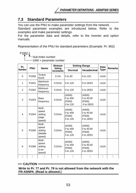
PARAMETER DEFINITIONS - A500/F500 SERIES
7.3 Standard ParametersYou can use the PNU to make parameter settings from the network.Standard parameter examples are introduced below. Refer to theexamples and make parameter settings.For the parameter data and details, refer to the inverter and optionmanuals.
Representation of the PNU for standard parameters (Example: Pr. 902)
Pr. Number PNU Name
Minimum Setting
Increments
Setting Range Data Type Remarks
Decimal Hexadecimal
0 P1000 Torque boost 0.1% 0 to 30 0 to 12C Us16
1 P1001 Maximum frequency 0.01Hz 0 to 120 0 to 2EE0 Us16
2 P1002 Minimum frequency 0.01Hz 0 to 120 0 to 2EE0 Us16
3 P1003 Base frequency 0.01Hz
(A500) 0 to 400(F500) 0 to 120
(A500) 0 to 9C40(F500) 0 to 2EE0
Us16
4 P1004
Multi-speed setting(High speed)
0.01Hz
(A500) 0 to 400(F500) 0 to 120
(A500) 0 to 9C40(F500) 0 to 2EE0
Us16
5 P1005
Multi-speed setting(Middle speed)
0.01Hz
(A500) 0 to 400(F500) 0 to 120
(A500) 0 to 9C40(F500) 0 to 2EE0
Us16
6 P1006
Multi-speed setting(Low speed)
0.01Hz
(A500) 0 to 400(F500) 0 to 120
(A500) 0 to 9C40(F500) 0 to 2EE0
Us16
··· ··· ··· ··· ··· ··· ··· ···
CAUTIONWrite to Pr. 77 and Pr. 79 is not allowed from the network with the FR-A5NPA. (Read is allowed.)
P1902.1Sub-Index number1000 + parameter number
53

PARAMETER DEFINITIONS - A500/F500 SERIES
The following parameters require the Sub-Index number for the PNU.
Pr. Number PNU Name
Minimum Setting
Increments
Setting Range Data Type Remarks
Decimal Hexadecimal
201 to 210
P1201.1 to
P1210.1
Program setting 1(Time)
0.01 0 to 99.59 0 to 26E7 AUs16
A500 series parame-ters
P1201.2 to
P1210.2
Program setting 1(Rotation direction)
1 0 to 2 0 to 2 AUs16
P1201.3 to
P1210.3
Program setting 1(Frequency)
0.1Hz 0 to 400, 9999
0 to 9C40, FFFF AUs16
211 to 220
P1211.1 to
P1220.1
Program setting 2(Time)
0.01 0 to 99.59 0 to 26E7 AUs16
P1211.2 to
P1220.2
Program setting 2(Rotation direction)
1 0 to 2 0 to 2 AUs16
P1211.3 to
P1220.3
Program setting 2(Frequency)
0.1Hz 0 to 400, 9999
0 to 9C40, FFFF AUs16
221 to 230
P1221.1 to
P1230.1
Program setting 3(Time)
0.01 0 to 99.59 0 to 26E7 AUs16
P1221.2 to
P1230.2
Program setting 3(Rotation direction)
1 0 to 2 0 to 2 AUs16
P1221.3 to
P1230.3
Program setting 3(Frequency)
0.1Hz 0 to 400, 9999
0 to 9C40, FFFF AUs16
900 P1900.1 FM terminal calibration - - - AUs16
901 P1901.1 AM terminal calibration - - - AUs16
902
P1902.1
Frequency setting voltage bias (frequency)
0.01Hz 0 to 60 0 to 1770 AUs16
P1902.2
Frequency setting voltage bias (%)
0.1% - - AUs16
54

PARAMETER DEFINITIONS - A500/F500 SERIES
903
P1903.1
Frequency setting voltage gain (frequency)
0.01Hz
(A500) 1 to 400(F500) 1 to 120
(A500)64 to 9C40(F500)64 to 2EE0
AUs16
P1903.2
Frequency setting voltage gain (%)
0.1% - - AUs16
904
P1904.1
Frequency setting current bias (frequency)
0.01Hz 0 to 60 0 to 1770 AUs16
P1904.2
Frequency setting current bias (%)
0.1% - - AUs16
905
P1905.1
Frequency setting current gain (frequency)
0.01Hz
(A500) 1 to 400(F500) 1 to 120
(A500)64 to 9C40(F500)64 to 2EE0
AUs16
P1905.2
Frequency setting current gain (%)
0.1% - - AUs16
Pr. Number PNU Name
Minimum Setting
Increments
Setting Range Data Type Remarks
Decimal Hexadecimal
55

8. PARAMETER DEFINITIONS - V500 SERIES
8.1 Outline of PNUYou can use the PNU to make inverter settings from the network.The data used with the network is denoted PNU(P) to differentiate it fromthe parameter (Pr.).
(1) PNU data definition
* When the data type is "with array", the Sub-Index number is included inthe PNU.
(2) PNU data typeThe PNU has the data types of "Array Unsigned 16" and "Unsigned 16".
CAUTIONThe parameter definitions differ between the FR-V500 and A500/F500 series. When using the A500/F500 series, refer to page 47.
Array Unsigned 16 Abbreviation:AUs16
With array
Unsigned 16 Abbreviation:Us16Without array
CAUTIONWhen the data type is "with array", include the Sub-Index number in the PNU.
P1902.1Sub-Index number*PNU number
P1902.1Sub-Index number
P1200
56

PARAMETER DEFINITIONS - V500 SERIES
8.2 Profibus PNU8.2.1 Real-time monitorThe following items can be monitored from the master.
PNU Item Unit Data Type
P1.1 Output frequency 0.01Hz AUs16P1.2 Output current 0.01A AUs16P1.3 Output voltage 0.1V AUs16P1.5 Speed setting 1r/min AUs16P1.6 Running speed 1r/min AUs16P1.7 Motor torque 0.1% AUs16P1.8 Converter output voltage 0.1V AUs16P1.9 Regenerative brake duty 0.1% AUs16
P1.10 Electronic thermal overload protection load factor 0.1% AUs16P1.11 Output current peak value 0.01A AUs16P1.12 Converter output voltage peak value 0.1V AUs16P1.15 Input terminal status (refer to page 58 (1)) - AUs16P1.16 Output terminal status (refer to page 58 (2)) - AUs16P1.17 Load meter 0.1% AUs16P1.18 Motor excitation current 0.01A AUs16P1.19 Position pulse - AUs16P1.20 Cumulative energization time 1h AUs16P1.23 Actual operation time 1h AUs16P1.24 Motor load factor 0.1% AUs16P1.32 Trace status 0.1% AUs16P1.33 Torque current command 0.1% AUs16P1.34 Motor output 0.01kW AUs16P1.35 Feedback pulse - AUs16P1.38 Trace status - AUs16
57

PARAMETER DEFINITIONS - V500 SERIES
(1) External input terminal status PWE bitmap
* Pr. 180 to Pr. 183 and Pr. 187 can be used to assign the terminal functions. Refer to the inverter manual for details of the terminal functions.
(2) External output terminal status PWE bitmap
* Pr. 190 to Pr. 192 and Pr. 195 can be used to assign the terminal functions. Refer to the inverter manual for details of the terminal functions.
STFSTR*DI1*DI2*DI3*DI4*OH*RES*00 0 00Terminal name
Not used (system reserved)
Bit 1415 13 12 11 10 9 8 7 6 012345
0 0 0
Terminal name
Not used (system reserved)
Bit
DO1*DO3*ABC*000 0 0 0 0 0 0 0 0
1415 13 12 11 10 9 8 7 6 0123450 DO2*
58

PARAMETER DEFINITIONS - V500 SERIES
8.2.2 Parameter clearParameter clear can be performed from the master.
*1 Communication parameters (Pr. 117 to Pr. 124, Pr. 331 to Pr. 342) are notcleared.
8.2.3 Operation mode read/writeRead/write of the operation mode can be performed from the master.
8.2.4 Set frequency readThe frequency set to the inverter can be read from the master.
PNU Item Data Definition Data TypeP2.2 Parameter clear 965AH AUs16P2.3 Parameter all clear 99AAH AUs16P2.5 Parameter clear (*1) 5A96H AUs16P2.6 Parameter all clear (*1) AA99H AUs16P2.8 Error history clear 0000H AUs16
PNU Item Data Definition Data Type
P3 Operation mode read/write NET :14HExternal :10H Us16
PNU Item Data Definition Data Type
P4.1 Set speed (RAM) read Set speed (RAM) is read. AUs16
P4.2 Set speed (E2PROM) read Set speed (E2PROM) is read.
AUs16
59

PARAMETER DEFINITIONS - V500 SERIES
8.2.5 Terminal input readThe setting of the No. 2 terminal can be read.
8.2.6 Inverter resetThe inverter can be reset from the master.
• The inverter maintains the resetting status while reset is requested.• When Pr. 75 ≠ "0, 2, 14, 16", reset is enabled only during an inverter
error.
8.2.7 Node address readThe node address of the inverter can be read.
PNU Item Data Definition Data Type
P5 No. 2 terminal input value read No. 2 terminal input value (%) is read. Us16
PNU Item Data Definition Data Type
P6 Inverter reset The inverter is reset after the data was written to the master. Us16
PNU Item Data Definition Data TypeP918 Node address read Set node address is read. Us16
60

PARAMETER DEFINITIONS - V500 SERIES
8.2.8 Alarm historyThe eight past error definitions of the inverter can be read.
<Error numbers>
* Refer to the inverter manual for details of the error definitions.
PNU Item Data Definition Data TypeP947.1 to P947.8
Error history No. 1 read
P947.1 :Error numberP947.2 to P947.8 :All 0 AUs16
P947.9 to P947.16
Error history No. 2 read
P947.9 :Error numberP947.10 to P947.16:All 0 AUs16
P947.17 to P947.24
Error history No. 3 read
P947.17 :Error numberP947.18 to P947.24:All 0 AUs16
P947.25 to P947.32
Error history No. 4 read
P947.25 :Error numberP947.26 to P947.32:All 0 AUs16
P947.33 to P947.40
Error history No. 5 read
P947.33 :Error numberP947.34 to P947.40:All 0 AUs16
P947.41 to P947.48
Error history No. 6 read
P947.41 :Error numberP947.42 to P947.48:All 0 AUs16
P947.49 to P947.56
Error history No. 7 read
P947.49 :Error numberP947.50 to P947.56:All 0 AUs16
P947.57 to P947.64
Error history No. 8 read
P947.57 :Error numberP947.58 to P947.64:All 0 AUs16
Error Number Definition Error
Number Definition Error Number Definition
00H No alarm 90H E.OHT D3H E.OD10H E.OC1 A0H E.OPT D4H E.ECA11H E.OC2 A1H E.OP1 D5H E.MB112H E.OC3 A2H E.OP2 D6H E.MB220H E.OV1 A3H E.OP3 D7H E.MB321H E.OV2 B0H E.PE D8H E.MB422H E.OV3 B1H E.PUE D9H E.MB530H E.THT B2H E.RET DAH E.MB631H E.THM C0H E.CPU DBH E.MB740H E.FIN C1H E.CTE DCH E.EP50H E.IPF C2H E.P24 F1H E. 151H E.UVT C3H E.P12 F2H E. 260H E.OLT D0H E.OS F3H E. 370H E.BE D1H E.OSD F6H E. 680H E.GF D2H E.ECT F7H E. 781H E.LF
61

PARAMETER DEFINITIONS - V500 SERIES
8.2.9 PNU list readThe usable PNU numbers can be read.
<PNU list read example>
*1 When 0 is stored, read is terminated.
PNU Item Data Definition Data TypeP980.1 to 116P981.1 to 116P982.1 to 116P983.1 to 116P984.1 to 116P985.1 to 116P986.1 to 116P987.1 to 116P988.1 to 116P989.1 to 116
PNU list read Usable PNU numbers are read in sorted status. AUs16
PNU NumberP980.1 1P980.2 2P980.3 3
: :P980.116 1000P981.1 1001P981.2 1002
: :P982.111 0 (*1)
62

PARAMETER DEFINITIONS - V500 SERIES
8.3 Standard ParametersYou can use the PNU to make parameter settings from the network.Standard parameter examples will be introduced. Refer to the examplesand make parameter settings.For the parameter data and details, refer to the inverter and optionmanuals.
Representation of the PNU for standard parameters (Example: Pr. 902)
Pr. Number PNU Name
Minimum Setting
Increments
Setting Range Data Type Remarks
Decimal Hexadecimal
0 P1000 Torque boost 0.1% 0 to 30 0 to 12C Us16
1 P1001 Maximum setting 1r/mim 0 to 3600 0 to E10 Us16
2 P1002 Minimum setting 1r/min 0 to 3600 0 to E10 Us16
3 P1003 Base frequency 0.01Hz 20 to 200 14 to 4E20 Us16
4 P1004
Multi-speed setting(High speed)
1r/min 0 to 3600 0 to E10 Us16
5 P1005
Multi-speed setting(Middle speed)
1r/min 0 to 3600 0 to E10 Us16
6 P1006
Multi-speed setting(Low speed)
1r/min 0 to 3600 0 to E10 Us16
··· ··· ··· ··· ··· ··· ··· ···
CAUTIONWrite to Pr. 77 and Pr. 79 is not allowed from the network with the FR-A5NPA. (Read is allowed.)
P1902.1Sub-Index number1000 + parameter number
63

PARAMETER DEFINITIONS - V500 SERIES
The following parameters require the Sub-Index number for the PNU.
Pr. Number PNU Name
Minimum Setting
Increments
Setting Range Data Type Remarks
Decimal Hexadecimal
900 P1900.1DA1 terminal calibration
- - - AUs16
901 P1901.1DA2 terminal calibration
- - - AUs16
902
P1902.1Speed setting No. 2 bias (speed)
0.1r/min 0 to 3600 0 to 8CA0 AUs16
P1902.2Speed setting No. 2 bias (%)
0.1% - - AUs16
903
P1903.1Speed setting No. 2 gain (speed)
1r/min 0 to 3600 0 to E10 AUs16
P1903.2Speed setting No. 2 gain (%)
0.1% - - AUs16
904
P1904.1
Torque command No. 3 bias (torque)
0.1% 0 to 400 0 to FA0 AUs16
P1904.2
Torque command No. 3 bias (%)
0.1% - - AUs16
905
P1905.1
Torque command No. 3 gain (torque)
0.1% 0 to 400 0 to FA0 AUs16
P1905.2
Torque command No. 3 gain (%)
0.1% - - AUs16
917
P1917.1No. 1 terminal bias (speed)
0.1r/min 0 to 3600 0 to 8CA0 AUs16 Speed
P1917.2No. 1 terminal bias (%)
0.1% - - AUs16 Speed
64

PARAMETER DEFINITIONS - V500 SERIES
918
P1918.1No. 1 terminal gain (speed)
1r/min 0 to 3600 0 to E10 AUs16 Speed
P1918.2No. 1 terminal gain (%)
0.1% - - AUs16 Speed
919
P1919.1
No. 1 terminal bias (torque)
0.1% 0 to 400 0 to FA0 AUs16Torque/mag-netic flux
P1919.2No. 1 terminal bias (%)
0.1% - - AUs16Torque/mag-netic flux
920
P1920.1No. 1 terminal gain (torque)
0.1% 0 to 400 0 to FA0 AUs16Torque/mag-netic flux
P1920.2No. 1 terminal gain (%)
0.1% - - AUs16Torque/mag-netic flux
Pr. Number PNU Name
Minimum Setting
Increments
Setting Range Data Type Remarks
Decimal Hexadecimal
65

9. TROUBLESHOOTING
If an alarm occurred in the inverter and the inverter and option unit do notfunction, refer to the following check points, find the cause from theoperation panel indication of the inverter and the LED status of the optionunit, and take an appropriate action. If any of the causes does not apply tothe alarm, a failure may have occurred. In that case, contact your salesrepresentative.* The error code of the inverter enters.
Operation Panel
IndicationOption Unit LED Status
Assumed Cause Check Point
0.00 Off
Option unit does not function.
Make sure that the option is fitted properly.Reset the inverter.Perform parameter all clear to return the parameters to the factory settings, and switch power off once, then on again.
Network is instable.
Make sure that the network cables between the nodes are connected properly.Make sure that the network cables are terminated.Check the network setting from the Profibus-DP Network Configuration Software.Check the other nodes for a network error.
Network master does not exist or does not function properly.
Check the connection and operation of the Profibus-DP master.
E.*** Off/on Inverter in error Refer to the inverter manual.
66

REVISIONS*The manual number is given on the bottom left of the back cover.
Print Date *Manual Number RevisionMay, 2002 IB(NA)-0600095-A First editionFeb., 2003 IB(NA)-0600095-B
• Command count• Inverter reset command
Additions


