27
Sequential Circuits Based partly on Patt and Patel Edited for CS470 by Y.K. Malaiya
Sequential Circuits
Based partly on Patt and Patel
Edited for CS470 by Y.K. Malaiya
Copyright © The McGraw-Hill Companies, Inc. Permission required for reproduction or display.
2CS470 - Spring 2013 - Colorado State University
State Machine
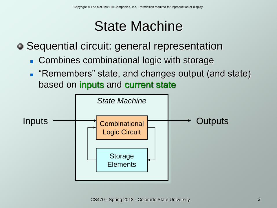
Sequential circuit: general representation
Combines combinational logic with storage
“Remembers” state, and changes output (and state)
based on inputs and current state
State Machine
Combinational
Logic Circuit
Storage
Elements
Inputs Outputs
Copyright © The McGraw-Hill Companies, Inc. Permission required for reproduction or display.
3CS470 - Spring 2013 - Colorado State University
Combinational vs. Sequential
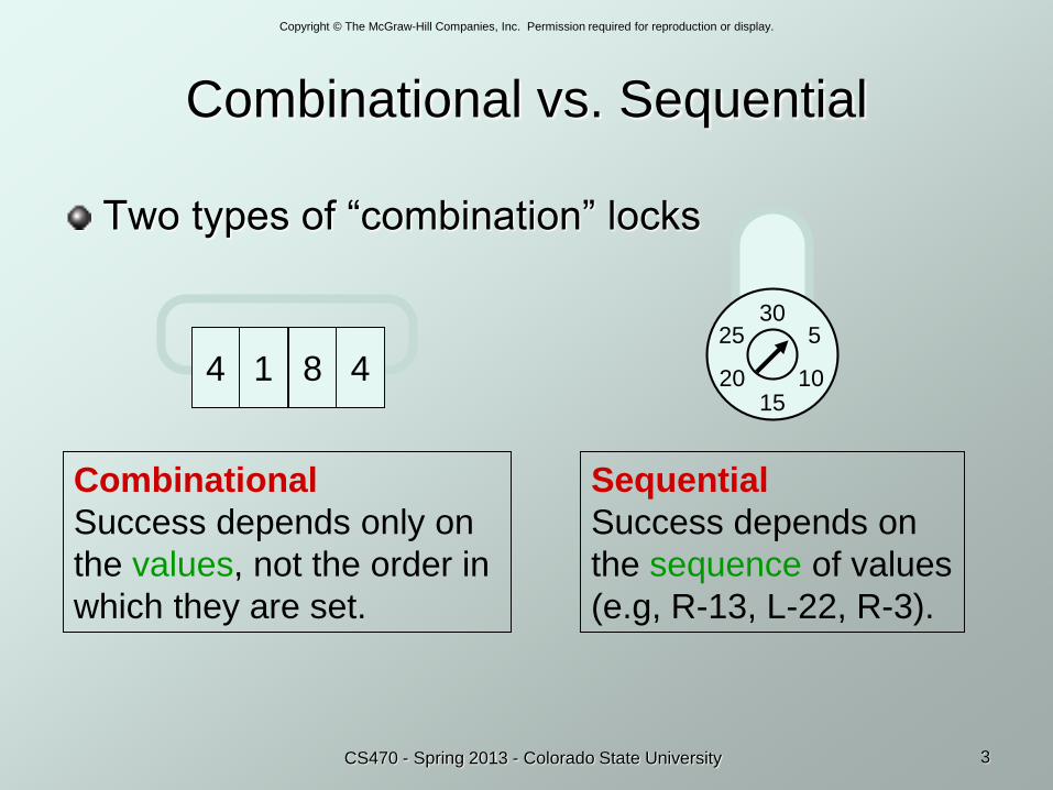
Two types of “combination” locks
4 1 8 4
30
15
5
1020
25
Combinational
Success depends only on
the values, not the order in
which they are set.
Sequential
Success depends on
the sequence of values
(e.g, R-13, L-22, R-3).
Copyright © The McGraw-Hill Companies, Inc. Permission required for reproduction or display.
4CS470 - Spring 2013 - Colorado State University
State
The state of a system is a snapshot of
all the relevant elements of the system
at the moment the snapshot is taken.
Examples:
The state of a basketball game can be represented by
the scoreboard: number of points, time remaining,
possession, etc.
The state of a tic-tac-toe game can be represented by
the placement of X’s and O’s on the board.
Copyright © The McGraw-Hill Companies, Inc. Permission required for reproduction or display.
5CS470 - Spring 2013 - Colorado State University
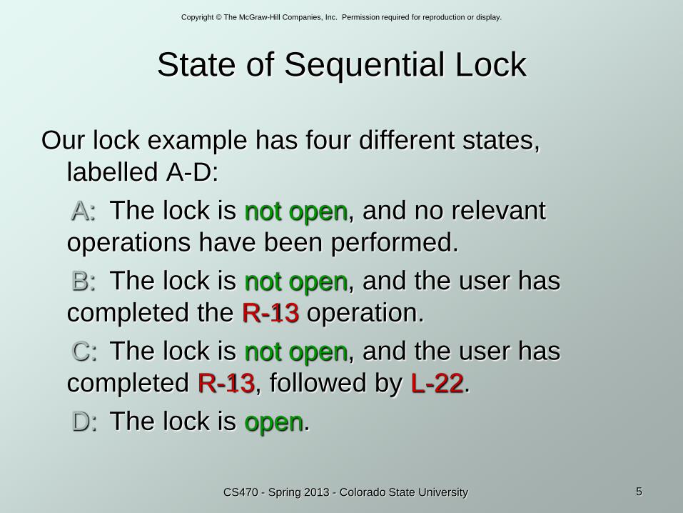
State of Sequential Lock
Our lock example has four different states,
labelled A-D:
A: The lock is not open, and no relevant
operations have been performed.
B: The lock is not open, and the user has
completed the R-13 operation.
C: The lock is not open, and the user has
completed R-13, followed by L-22.
D: The lock is open.
Copyright © The McGraw-Hill Companies, Inc. Permission required for reproduction or display.
6CS470 - Spring 2013 - Colorado State University
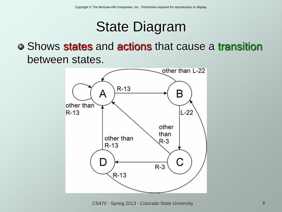
State Diagram
Shows states and actions that cause a transition
between states.
Copyright © The McGraw-Hill Companies, Inc. Permission required for reproduction or display.
7CS470 - Spring 2013 - Colorado State University
Finite State MachineA system with the following components:
1. A finite number of states
2. A finite number of external inputs and outputs
3. An explicit specification of all state transitions and
external output value
Often described by a state table or state diagram.
External outputs as well as Next state depend on
Present State
Inputs
Copyright © The McGraw-Hill Companies, Inc. Permission required for reproduction or display.
8CS470 - Spring 2013 - Colorado State University
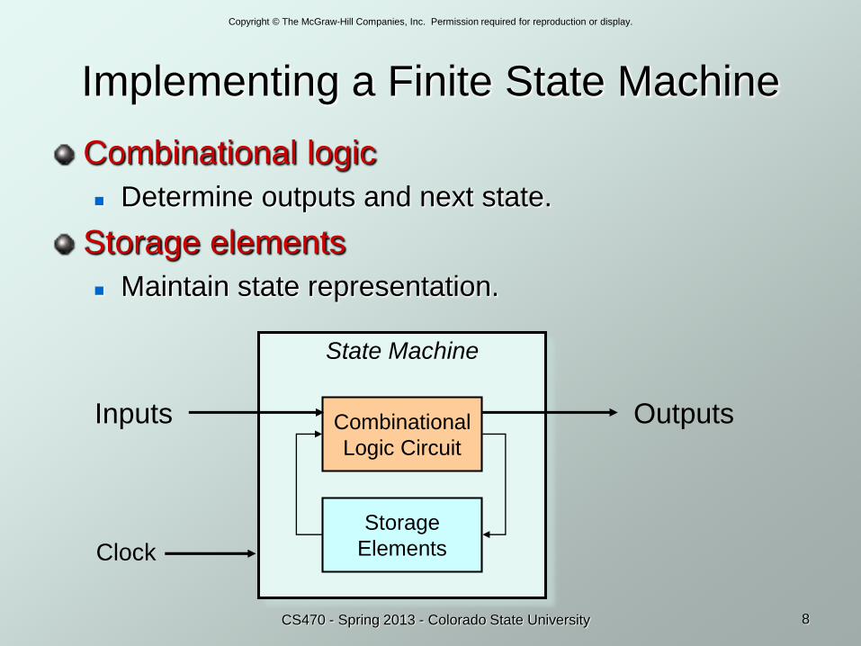
Implementing a Finite State Machine
Combinational logic
Determine outputs and next state.
Storage elements
Maintain state representation.
State Machine
Combinational
Logic Circuit
Storage
Elements
Inputs Outputs
Clock
Copyright © The McGraw-Hill Companies, Inc. Permission required for reproduction or display.
9CS470 - Spring 2013 - Colorado State University
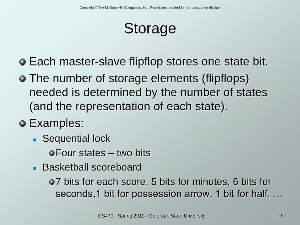
Storage
Each master-slave flipflop stores one state bit.
The number of storage elements (flipflops)
needed is determined by the number of states
(and the representation of each state).
Examples:
Sequential lock
Four states – two bits
Basketball scoreboard
7 bits for each score, 5 bits for minutes, 6 bits for
seconds,1 bit for possession arrow, 1 bit for half, …
Copyright © The McGraw-Hill Companies, Inc. Permission required for reproduction or display.
CS470 - Spring 2013 - Colorado State
University 10
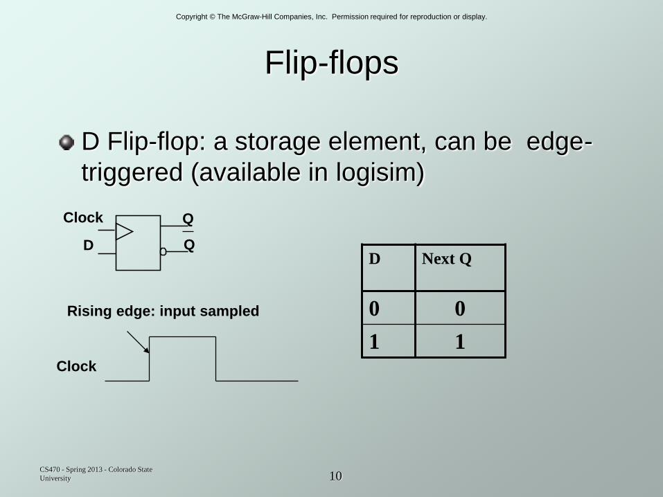
Flip-flops
D Flip-flop: a storage element, can be edge-
triggered (available in logisim)
Q
Q
Clock
DD Next Q
0 0
1 1Clock
Rising edge: input sampled
Copyright © The McGraw-Hill Companies, Inc. Permission required for reproduction or display.
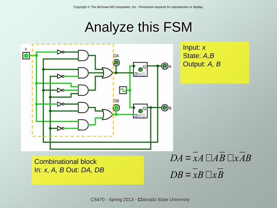
Analyze this FSM
11
Input: x
State: A,B
Output: A, B
Combinational block
In: x, A, B Out: DA, DB
DA = xA+ AB+ xAB
DB = xB+ xB
CS470 - Spring 2013 - Colorado State University
Copyright © The McGraw-Hill Companies, Inc. Permission required for reproduction or display.
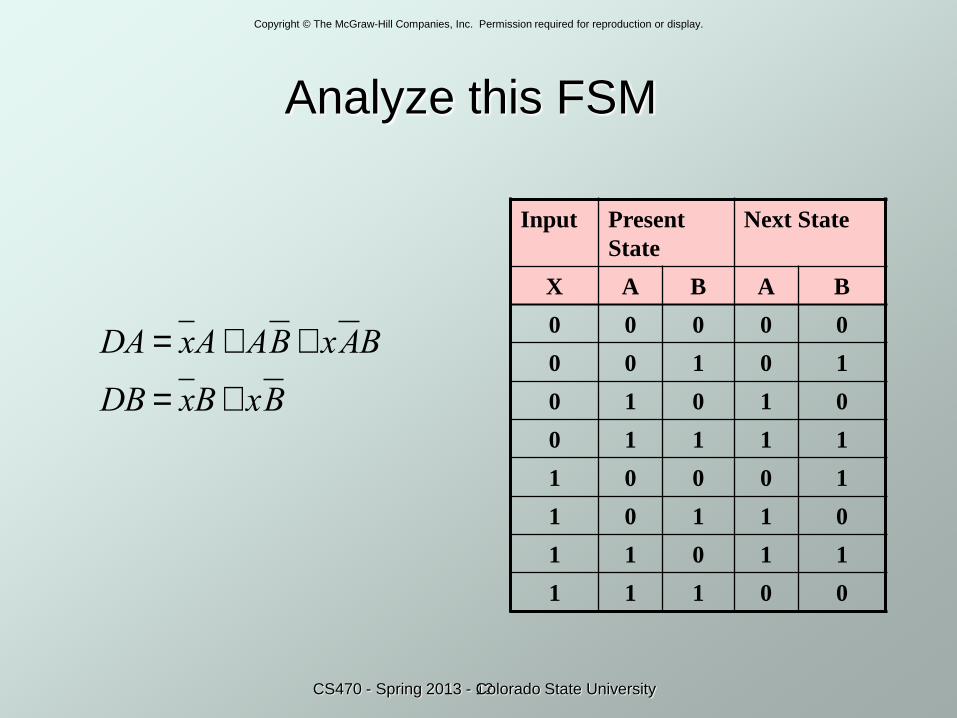
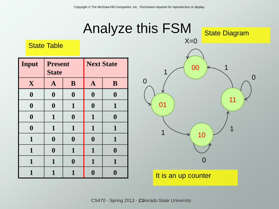
Analyze this FSM
12
Input Present
State
Next State
X A B A B
0 0 0 0 0
0 0 1 0 1
0 1 0 1 0
0 1 1 1 1
1 0 0 0 1
1 0 1 1 0
1 1 0 1 1
1 1 1 0 0
DA = xA+ AB+ xAB
DB = xB+ xB
CS470 - Spring 2013 - Colorado State University
Copyright © The McGraw-Hill Companies, Inc. Permission required for reproduction or display.
Analyze this FSM
13
Input Present
State
Next State
X A B A B
0 0 0 0 0
0 0 1 0 1
0 1 0 1 0
0 1 1 1 1
1 0 0 0 1
1 0 1 1 0
1 1 0 1 1
1 1 1 0 0
00
01
10
11
X=0
1
0
11
1
0
0
It is an up counter
State Table
State Diagram
CS470 - Spring 2013 - Colorado State University
Copyright © The McGraw-Hill Companies, Inc. Permission required for reproduction or display.
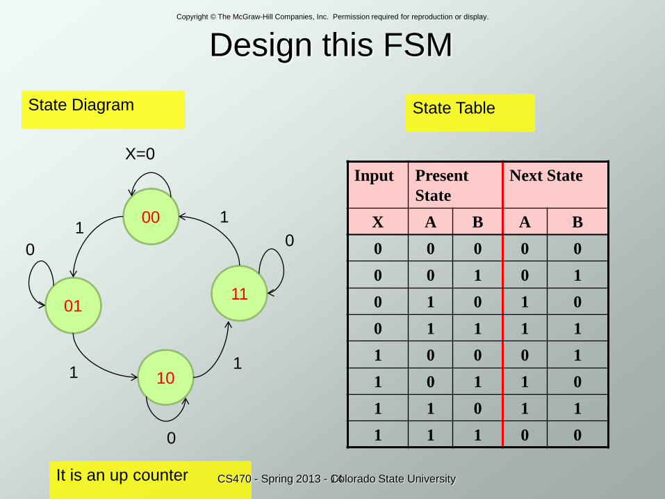
Design this FSM
14
Input Present
State
Next State
X A B A B
0 0 0 0 0
0 0 1 0 1
0 1 0 1 0
0 1 1 1 1
1 0 0 0 1
1 0 1 1 0
1 1 0 1 1
1 1 1 0 0
00
01
10
11
X=0
1
0
11
1
0
0
It is an up counter
State TableState Diagram
CS470 - Spring 2013 - Colorado State University
Copyright © The McGraw-Hill Companies, Inc. Permission required for reproduction or display.
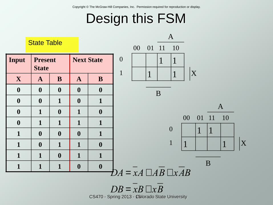
Design this FSM
15
Input Present
State
Next State
X A B A B
0 0 0 0 0
0 0 1 0 1
0 1 0 1 0
0 1 1 1 1
1 0 0 0 1
1 0 1 1 0
1 1 0 1 1
1 1 1 0 0
State Table
CS470 - Spring 2013 - Colorado State University
A
00 01 11 10
0 1 1
1 1 1 X
B
A
00 01 11 10
0 1 1
1 1 1 X
B
DA = xA+ AB+ xAB
DB = xB+ xB
Copyright © The McGraw-Hill Companies, Inc. Permission required for reproduction or display.
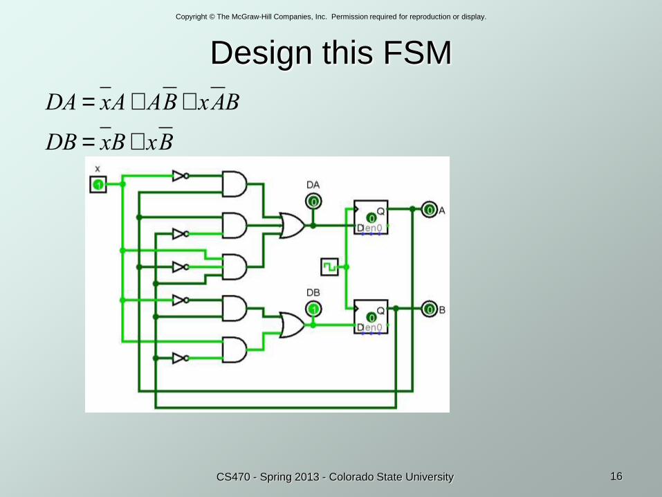
Design this FSM
16CS470 - Spring 2013 - Colorado State University
DA = xA+ AB+ xAB
DB = xB+ xB
Copyright © The McGraw-Hill Companies, Inc. Permission required for reproduction or display.
17CS470 - Spring 2013 - Colorado State University
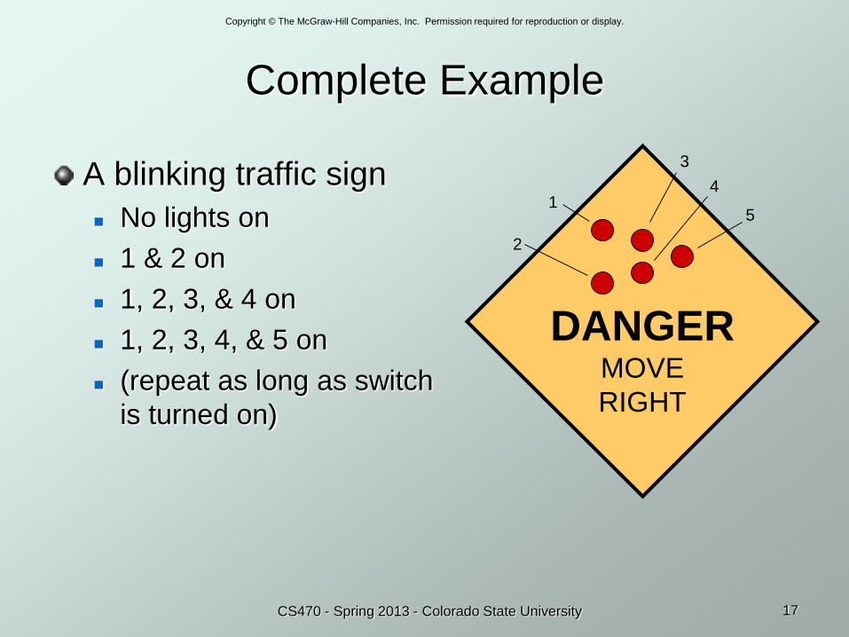
Complete Example
A blinking traffic sign
No lights on
1 & 2 on
1, 2, 3, & 4 on
1, 2, 3, 4, & 5 on
(repeat as long as switch
is turned on)
DANGERMOVE
RIGHT
1
2
3
4
5

Copyright © The McGraw-Hill Companies, Inc. Permission required for reproduction or display.
18CS470 - Spring 2013 - Colorado State University
Traffic Sign State Diagram
State bit S1 State bit S0
Switch on
Switch off
Outputs
Transition on each clock cycle.
Copyright © The McGraw-Hill Companies, Inc. Permission required for reproduction or display.
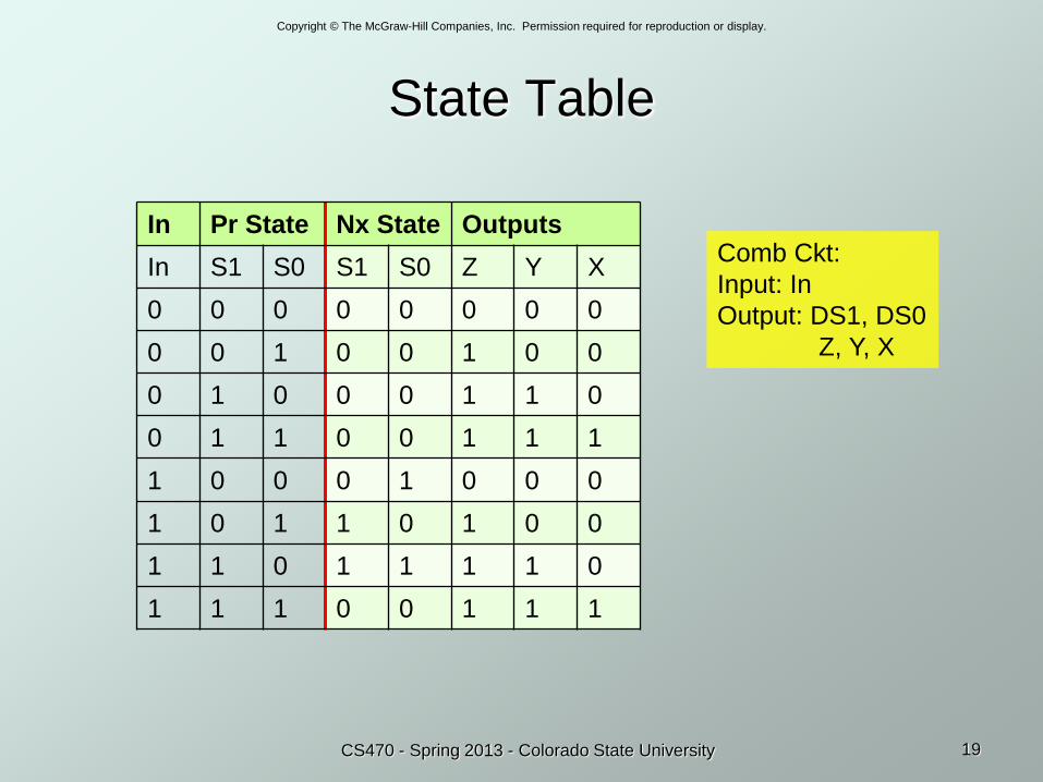
State Table
In Pr State Nx State Outputs
In S1 S0 S1 S0 Z Y X
0 0 0 0 0 0 0 0
0 0 1 0 0 1 0 0
0 1 0 0 0 1 1 0
0 1 1 0 0 1 1 1
1 0 0 0 1 0 0 0
1 0 1 1 0 1 0 0
1 1 0 1 1 1 1 0
1 1 1 0 0 1 1 1
19CS470 - Spring 2013 - Colorado State University
Comb Ckt:
Input: In
Output: DS1, DS0
Z, Y, X
Copyright © The McGraw-Hill Companies, Inc. Permission required for reproduction or display.
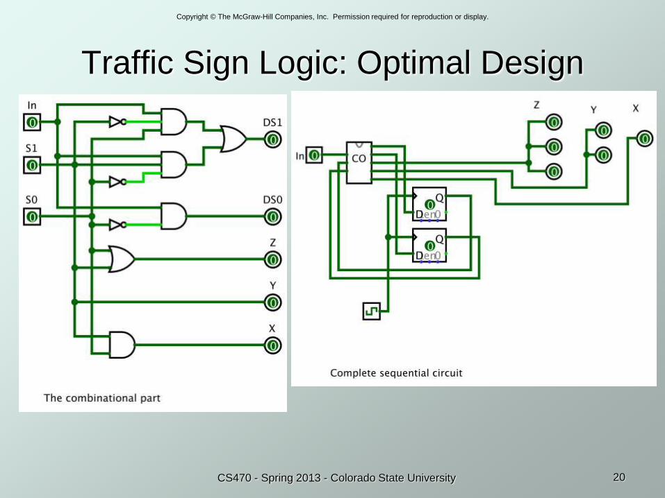
Traffic Sign Logic: Optimal Design
20CS470 - Spring 2013 - Colorado State University
Copyright © The McGraw-Hill Companies, Inc. Permission required for reproduction or display.
21CS470 - Spring 2013 - Colorado State University
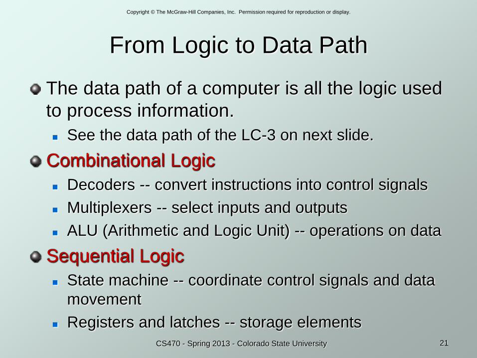
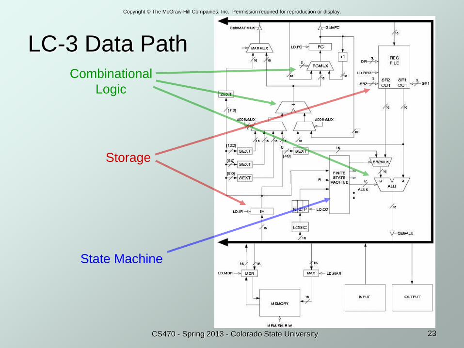
From Logic to Data Path
The data path of a computer is all the logic used
to process information.
See the data path of the LC-3 on next slide.
Combinational Logic
Decoders -- convert instructions into control signals
Multiplexers -- select inputs and outputs
ALU (Arithmetic and Logic Unit) -- operations on data
Sequential Logic
State machine -- coordinate control signals and data
movement
Registers and latches -- storage elements
Copyright © The McGraw-Hill Companies, Inc. Permission required for reproduction or display.
2/5/2016Discrete math YKM 22
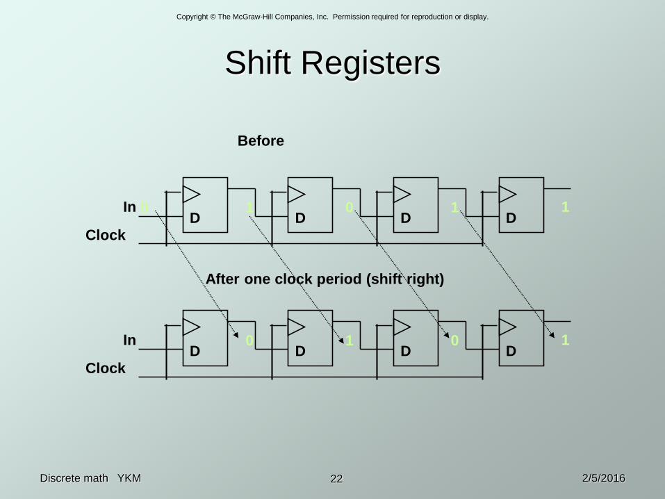
Shift Registers
D D D DClock
In 0 1 0 1 1
D D D DClock
In 0 1 0 1
After one clock period (shift right)
Before
Copyright © The McGraw-Hill Companies, Inc. Permission required for reproduction or display.
23CS470 - Spring 2013 - Colorado State University
LC-3 Data PathCombinational
Logic
State Machine
Storage
Copyright © The McGraw-Hill Companies, Inc. Permission required for reproduction or display.
2/5/2016Discrete math YKM 24
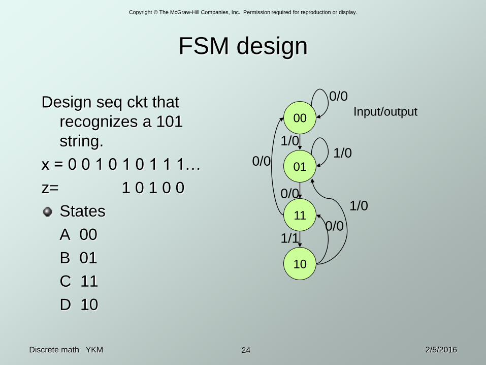
FSM design
Design seq ckt that
recognizes a 101
string.
x = 0 0 1 0 1 0 1 1 1…
z= 1 0 1 0 0
States
A 00
B 01
C 11
D 10
00
10
11
01
0/0
1/01/0
1/00/0
0/0
0/0
1/1
Input/output
Copyright © The McGraw-Hill Companies, Inc. Permission required for reproduction or display.
2/5/2016Discrete math YKM 25
FSM designy0
00 01 11 10
0 1
1 1 1 y1
x
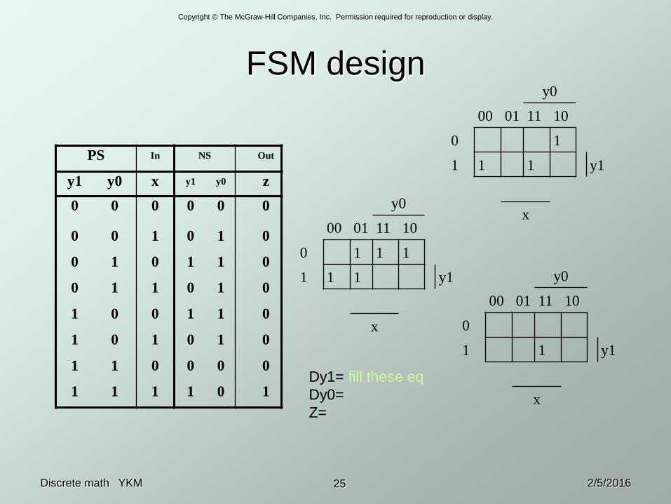
PS In NS Out
y1 y0 x y1 y0 z
0 0 0 0 0 0
0 0 1 0 1 0
0 1 0 1 1 0
0 1 1 0 1 0
1 0 0 1 1 0
1 0 1 0 1 0
1 1 0 0 0 0
1 1 1 1 0 1
y0
00 01 11 10
0 1 1 1
1 1 1 y1
x
y0
00 01 11 10
0
1 1 y1
x
Dy1= fill these eq
Dy0=
Z=
Copyright © The McGraw-Hill Companies, Inc. Permission required for reproduction or display.
2/5/2016Discrete math YKM 26
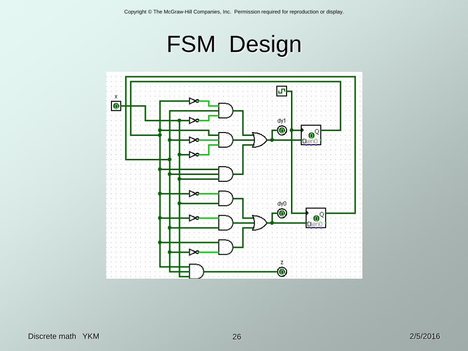
FSM Design
Copyright © The McGraw-Hill Companies, Inc. Permission required for reproduction or display.
2/5/2016Discrete math YKM 27
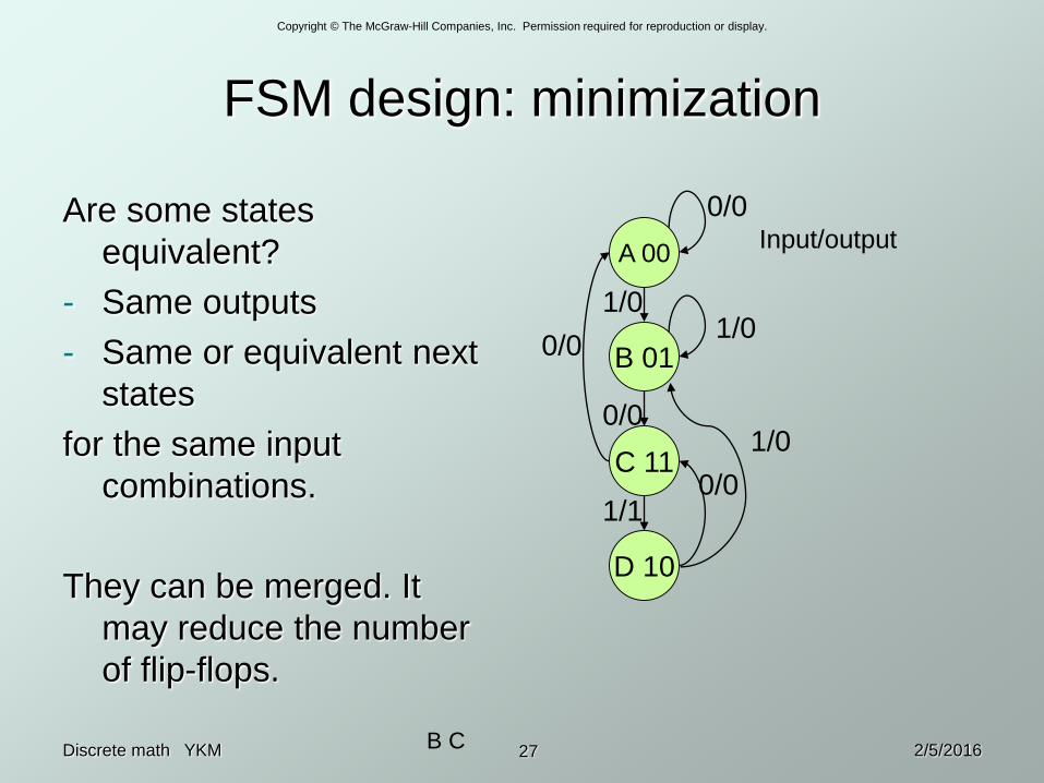
FSM design: minimization
Are some states
equivalent?
- Same outputs
- Same or equivalent next
states
for the same input
combinations.
They can be merged. It
may reduce the number
of flip-flops.
A 00
D 10
C 11
B 01
0/0
1/01/0
1/00/0
0/0
0/0
1/1
Input/output
B C


