Transit Cooperative Research Program Sponsored by the Federal Transit Administration RESEARCH RESULTS DIGEST April 1998--Number 25 Subject Area: VI Public Transit Responsible Senior Program Officer: Christopher W Jenks Technology Assessment of Refueling-Connection Devices for CNG, LNG, and Propane This TCRP digest provides the results of TCRP Project C-7, "Technology Assessment of Refueling-Connection Devices for CNG, LNG, and Propane," conducted by Science Applications International Corporation (SAIC). INTRODUCTION This digest provides an assessment of current and emerging refueling-connection-device (nozzle) technologies (both domestic and international) for fueling alternative fuel vehicles (AFVs). The nozzle technologies discussed in this digest are those used for refueling with compressed natural gas (CNG), liquefied natural gas (LNG), and liquefied petroleum gas (LPG, commonly referred to as propane). The discussion covers all types of nozzles for the listed fuels. However, the analytical work focuses on nozzles used in heavyduty applications, specifically, transit buses. Background CNG and LPG vehicles have been used worldwide for several decades. Countries such as Australia, Canada, Germany, Italy, the Netherlands, New Zealand, and Russia have a long history of CNG and LPG vehicle usage. Technological developments in these countries and in the United States have influenced the development of current nozzles. More recently, the use of CNG, LNG, and LPG has become more common in South American countries, such as Argentina, Brazil, and Venezuela, and in Central and Eastern European countries, such as the Czech Republic, Poland, and Slovakia. The South American and Eastern European countries have had little influence on U.S. nozzle technologies. In the United States, the use of LPG as a transportation fuel has been popular since World War II. Although not commonly used in heavy-duty transit applications, the Chicago Transit Authority was operating more than 1,700 LPG- powered buses between 1950 and 1963. In the early 1970s, Chicago phased out the use of LPG, largely because of unfavorable economics. Today, there are more than 200,000 on-road LPG vehicles and about an equal number of off-road vehicles in the United States. However, there are only several dozen transit buses using LPG. The use of CNG and LNG for vehicular applications gained popularity in the late 1980s. By the end of 1997, about 65,000 vehicles used CNG (a six-fold increase from 1990). At the same time, approximately 1,000 LNG vehicles were in use worldwide, of which 700 were in the United States. 1 Because of this early experience, the United States has pioneered the development of nozzles used for fueling LNG vehicles. In general, the United States is the most progressive country with respect to the development of standards and regulations for CNG and LNG vehicles, vehicle-related technologies, and emissions. However, the United States is not the leader in setting LPG standards and in developing LPG technologies. Countries such as Australia, Canada, Germany, Italy, and the Netherlands have more advanced LPG industries, which corresponds with more widespread use of LPG vehicles. _______________________________ 1 Science Applications International Corporation, estimates, derived from SAIC's 1997 Natural Gas Vehicle (NGV) Survey. TRANSPORTATION RESEARCH BOARD NATIONAL RESEARCH COUNCIL
Transcript
Transit Cooperative Research ProgramSponsored by the Federal Transit Administration
RESEARCH RESULTS DIGESTApril 1998--Number 25
Subject Area: VI Public Transit Responsible Senior Program Officer: Christopher W Jenks
Technology Assessment of Refueling-ConnectionDevices for CNG, LNG, and Propane
This TCRP digest provides the results of TCRP Project C-7, "Technology Assessment of Refueling-ConnectionDevices for CNG, LNG, and Propane," conducted by Science Applications International Corporation (SAIC).
INTRODUCTION
This digest provides an assessment of currentand emerging refueling-connection-device (nozzle)technologies (both domestic and international) forfueling alternative fuel vehicles (AFVs). The nozzletechnologies discussed in this digest are those usedfor refueling with compressed natural gas (CNG),liquefied natural gas (LNG), and liquefied petroleumgas (LPG, commonly referred to as propane). Thediscussion covers all types of nozzles for the listedfuels. However, the analytical work focuses onnozzles used in heavyduty applications, specifically,transit buses.
Background
CNG and LPG vehicles have been usedworldwide for several decades. Countries such asAustralia, Canada, Germany, Italy, the Netherlands,New Zealand, and Russia have a long history of CNGand LPG vehicle usage. Technological developmentsin these countries and in the United States haveinfluenced the development of current nozzles. Morerecently, the use of CNG, LNG, and LPG has becomemore common in South American countries, such asArgentina, Brazil, and Venezuela, and in Central andEastern European countries, such as the CzechRepublic, Poland, and Slovakia. The South Americanand Eastern European countries have had littleinfluence on U.S. nozzle technologies.
In the United States, the use of LPG as atransportation fuel has been popular since
World War II. Although not commonly used inheavy-duty transit applications, the Chicago TransitAuthority was operating more than 1,700 LPG-powered buses between 1950 and 1963. In the early1970s, Chicago phased out the use of LPG, largelybecause of unfavorable economics. Today, there aremore than 200,000 on-road LPG vehicles and aboutan equal number of off-road vehicles in the UnitedStates. However, there are only several dozen transitbuses using LPG. The use of CNG and LNG forvehicular applications gained popularity in the late1980s. By the end of 1997, about 65,000 vehiclesused CNG (a six-fold increase from 1990). At thesame time, approximately 1,000 LNG vehicles werein use worldwide, of which 700 were in the UnitedStates.1 Because of this early experience, the UnitedStates has pioneered the development of nozzles usedfor fueling LNG vehicles.
In general, the United States is the mostprogressive country with respect to the developmentof standards and regulations for CNG and LNGvehicles, vehicle-related technologies, and emissions.However, the United States is not the leader in settingLPG standards and in developing LPG technologies.Countries such as Australia, Canada, Germany, Italy,and the Netherlands have more advanced LPGindustries, which corresponds with more widespreaduse of LPG vehicles.
_______________________________
1 Science Applications International Corporation,estimates, derived from SAIC's 1997 Natural Gas Vehicle(NGV) Survey.
TRANSPORTATION RESEARCH BOARDNATIONAL RESEARCH COUNCIL
Existing and Future or Proposed Regulations, Codes, and Standards, 5Existing Regulations, Codes, and Standards, 6Future or Proposed Regulations, Codes, and Standards, 7Discussion, 8
CNG Nozzles, 8Description and Features, 9Principles of Operation, 9Dead Space Volume (Nozzle and Receptacle), 12Safety, 12Performance Specifications, 13Operational Issues, 13
LNG Nozzles, 18Description and Features, 18Alternative Designs, 22Principles of Operation, 22Dead Space Volume (Nozzle and Receptacle), 28Safety, 28Performance Specifications, 29Operational Issues, 29
LPG Nozzles, 29Description and Features, 30Principles of Operation, 30Dead Space Volume (Nozzle and Receptacle), 33Safety, 33Operational Issues, 34
APPENDIX A: Methane Releases in Perspective, 40APPENDIX B: Nozzle Manufacturer Information Surveys, 42
NOTE: The Transportation Research Board, the National Research Council, the Transit Development Corporation, and theFederal Transit Administration (sponsor of the Transit Cooperative Research Program) do not endorse products or manufacturers.Trade or manufacturers' names appear herein solely because they are considered essential to the clarity and completeness of theproject reporting.
3
Overseas manufacturers of LPG and CNG nozzles areproducing and will continue to develop nozzles that meetU.S. regulatory and market requirements. Many Europeancountries are focusing on urban emissions, especiallytransit bus emissions. As a result, certain countries (e.g.,Germany, Denmark, Italy, the Netherlands) may surpassthe United States in the control of emissions from LPG andCNG nozzles. There is no evidence to indicate that foreigntechnology developers are working on LNG nozzledevelopment. It appears that in the short term, LNG nozzledevelopments will continue to occur predominantly in theUnited States.
Scope
This digest provides a summary of nozzle legislationand technologies for CNG, LNG, and LPG. The scope ofthe work covers only the technology that affects the deadspace volume (DSV), which can retain fuel after fuelingcompletion, and results in the venting of that fuel to theatmosphere. The scope does not include the review of othersources of fueling-related emissions (e.g., poor connectionsor leaky hoses), which, in some cases, account for fargreater amounts of fueling-related emissions.
Approach
The research team reviewed CNG, LNG, and LPGnozzle-related regulations. A summary of this activity ispresented in the section on "Existing and Future orProposed Regulations, Codes, and Standards" (page 5). Theresearchers also conducted a technical and operationalreview of U.S. and international nozzle technologies todetermine their ability to meet current and potential futureemissions limits during coupling and decoupling.
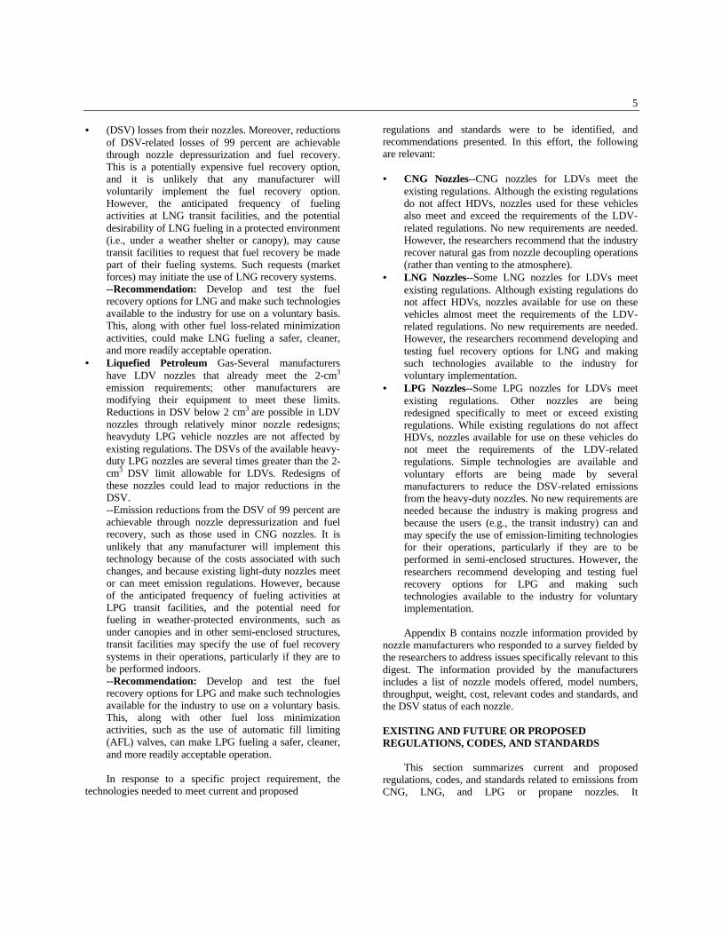
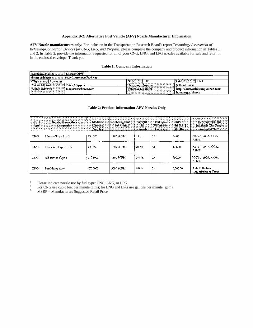
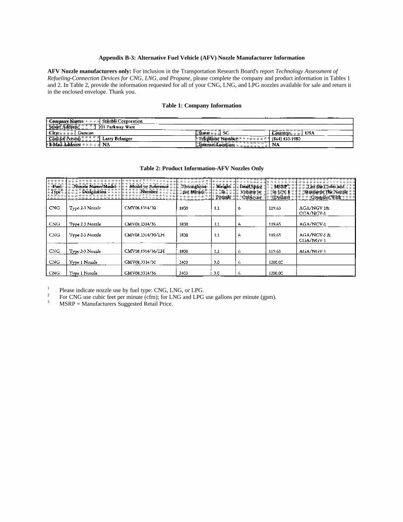
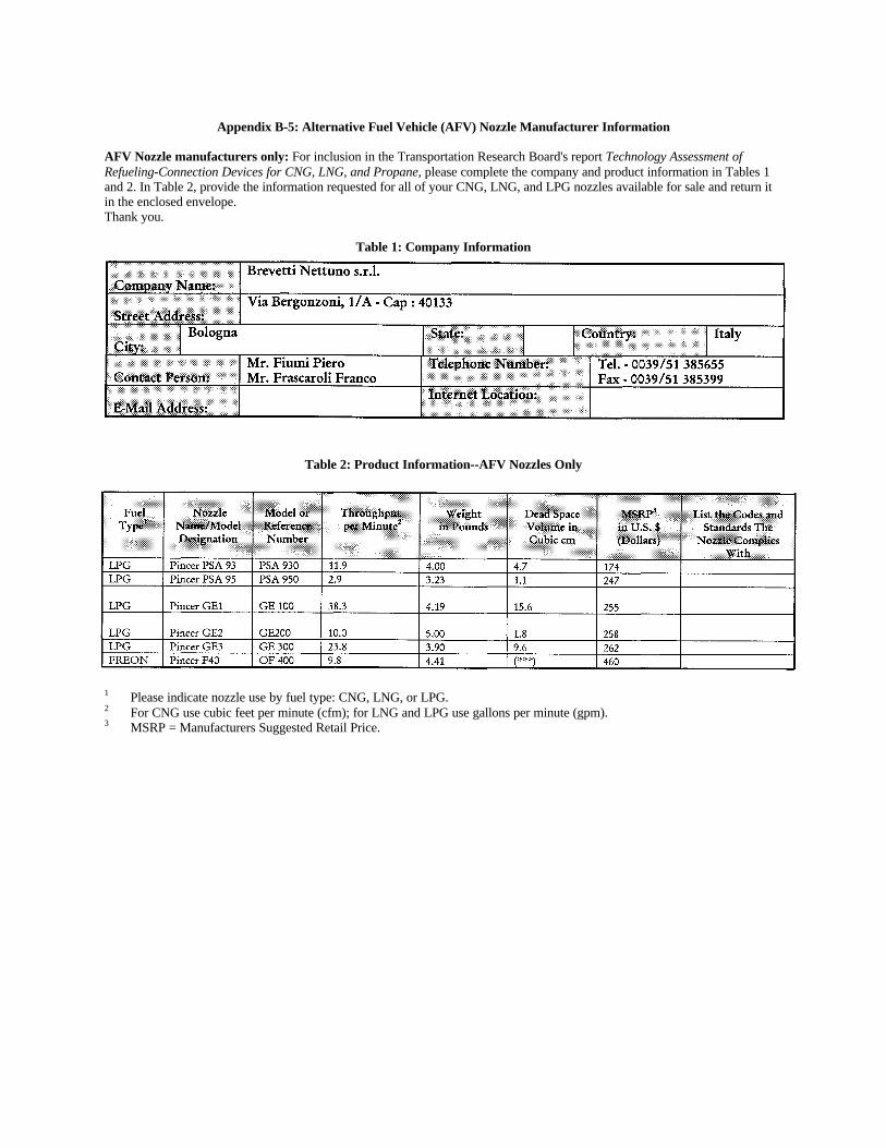
The research team contacted the manufacturers shownin Table 1, visited several nozzle manufacturers, andstudied nozzle technologies at manufacturers' sites for eachof the three fuels. In the United States, the team visited theplants of Moog and Sherex and met with key staff fromParker Hannifin. Internationally, visits were made toStäubli (a European manufacturer of CNG nozzlesinterested in launching an LPG product line) and BrevettiNettuno (an Italian manufacturer of LPG nozzles). Theteam also observed CNG and LPG fueling operations inseveral countries in Europe.
The discussions of U.S. and international technologiesare merged because there are no major differences betweenU.S. and foreign products. The only relevant differencebetween the two is that LPG products are primarily offoreign origin and LNG products are predominantly of U.S.design and origin. Several U.S.
fueling sites were visited to observe operational-, safety-,and performance-related factors. For instance, the projectteam visited the LNG and CNG fueling sites at HoustonMetro (Texas), the LPG public fueling stations in Rockville(Maryland) and in Fairfax (Virginia), the transit LPGfueling station in Corpus Christi (Texas), and the new CNGfueling stations at GRI in Chicago (Illinois) and at LongIsland Bus (New York). In addition, information obtainedfrom observations made during past visits to CNG andLNG transit properties is incorporated in this digest. Videotapes made or obtained from other sources were viewed toassist in assessing use-related factors.
Summary
The summary findings and recommendations of thisdigest, by fuel, are as follows:
•• Compressed Natural Gas--Redesigning existingCNG nozzles to reduce emissions from the decouplingoperation is possible, but not recommended, becauseCNG nozzles already meet or exceed the requirementsof the newly implemented emissions regulations. Thisis true for nozzles used for both light-duty vehicles(LDVs) and heavy-duty vehicles (HDVs) even incases where the fuel is not recovered (i.e., is vented tothe atmosphere). Throughout the industry, emissionsfrom theCNG nozzle DSVs can be reduced by using thedepressurization available on all CNG fueling systemsthrough fuel recovery (rather than venting to theatmosphere). Several states and technicalspecifications require such recoveries. However, thesespecifications are not universally followed. The use offuel recovery on a widespread basis would make CNGemissions from the CNG nozzle connection anddisconnection processes insignificant compared to thedecoupling-related losses associated with other fuels.Compared to other sources of methane (the maincomponent of natural gas) emissions, methane lossesfrom CNG fueling operations are insignificant (seeAppendix A). More radical redesigns, which couldoffer near-zero emissions, should evolve throughmarket forces.--Recommendation: Encourage the industry torecover natural gas from nozzle decoupling operations(rather than venting to the atmosphere).
•• Liquefied Natural Gas-Heavy-duty LNG nozzlelosses from the DSV are as low as 2.4 cm3 of liquid.Developers of a new nozzle design claim "zero-emissions" (to be interpreted as very low rather than as0.0 cm3). Manufacturers of another nozzle report thatefforts are under way to minimize fueling-related
TABLE 1 Nozzle manufacturers
Fuel Type/Company Site of Manufacture † Product
LPG
Brevetti Nettuno, s.r.l. Bologna, Italy LPG Gas Erogator Gun
Gibson Technical Services Puyallup, Washington LNG Coupling
Hiltap Calgary, Alberta LNG Coupling (prototype)
Whittaker Controls, Inc. North Hollywood, California Experimental
A. Livsey Houston, Texas Experimental
Source: Science Applications International Corporation, Transportation Consulting Division, September 1996.
† Some manufacturers have multiple manufacturing sites.
Note: This table represents the best information available to the researchers at the time the report was written. Other suppliersmight have existed and any omissions were inadvertent.
5
•• (DSV) losses from their nozzles. Moreover, reductionsof DSV-related losses of 99 percent are achievablethrough nozzle depressurization and fuel recovery.This is a potentially expensive fuel recovery option,and it is unlikely that any manufacturer willvoluntarily implement the fuel recovery option.However, the anticipated frequency of fuelingactivities at LNG transit facilities, and the potentialdesirability of LNG fueling in a protected environment(i.e., under a weather shelter or canopy), may causetransit facilities to request that fuel recovery be madepart of their fueling systems. Such requests (marketforces) may initiate the use of LNG recovery systems.--Recommendation: Develop and test the fuelrecovery options for LNG and make such technologiesavailable to the industry for use on a voluntary basis.This, along with other fuel loss-related minimizationactivities, could make LNG fueling a safer, cleaner,and more readily acceptable operation.
•• Liquefied Petroleum Gas-Several manufacturershave LDV nozzles that already meet the 2-cm3
emission requirements; other manufacturers aremodifying their equipment to meet these limits.Reductions in DSV below 2 cm3 are possible in LDVnozzles through relatively minor nozzle redesigns;heavyduty LPG vehicle nozzles are not affected byexisting regulations. The DSVs of the available heavy-duty LPG nozzles are several times greater than the 2-cm3 DSV limit allowable for LDVs. Redesigns ofthese nozzles could lead to major reductions in theDSV.--Emission reductions from the DSV of 99 percent areachievable through nozzle depressurization and fuelrecovery, such as those used in CNG nozzles. It isunlikely that any manufacturer will implement thistechnology because of the costs associated with suchchanges, and because existing light-duty nozzles meetor can meet emission regulations. However, becauseof the anticipated frequency of fueling activities atLPG transit facilities, and the potential need forfueling in weather-protected environments, such asunder canopies and in other semi-enclosed structures,transit facilities may specify the use of fuel recoverysystems in their operations, particularly if they are tobe performed indoors.--Recommendation: Develop and test the fuelrecovery options for LPG and make such technologiesavailable for the industry to use on a voluntary basis.This, along with other fuel loss minimizationactivities, such as the use of automatic fill limiting(AFL) valves, can make LPG fueling a safer, cleaner,and more readily acceptable operation.
In response to a specific project requirement, thetechnologies needed to meet current and proposed
regulations and standards were to be identified, andrecommendations presented. In this effort, the followingare relevant:
•• CNG Nozzles--CNG nozzles for LDVs meet theexisting regulations. Although the existing regulationsdo not affect HDVs, nozzles used for these vehiclesalso meet and exceed the requirements of the LDV-related regulations. No new requirements are needed.However, the researchers recommend that the industryrecover natural gas from nozzle decoupling operations(rather than venting to the atmosphere).
•• LNG Nozzles--Some LNG nozzles for LDVs meetexisting regulations. Although existing regulations donot affect HDVs, nozzles available for use on thesevehicles almost meet the requirements of the LDV-related regulations. No new requirements are needed.However, the researchers recommend developing andtesting fuel recovery options for LNG and makingsuch technologies available to the industry forvoluntary implementation.
•• LPG Nozzles--Some LPG nozzles for LDVs meetexisting regulations. Other nozzles are beingredesigned specifically to meet or exceed existingregulations. While existing regulations do not affectHDVs, nozzles available for use on these vehicles donot meet the requirements of the LDV-relatedregulations. Simple technologies are available andvoluntary efforts are being made by severalmanufacturers to reduce the DSV-related emissionsfrom the heavy-duty nozzles. No new requirements areneeded because the industry is making progress andbecause the users (e.g., the transit industry) can andmay specify the use of emission-limiting technologiesfor their operations, particularly if they are to beperformed in semi-enclosed structures. However, theresearchers recommend developing and testing fuelrecovery options for LPG and making suchtechnologies available to the industry for voluntaryimplementation.
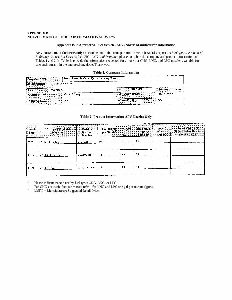
Appendix B contains nozzle information provided bynozzle manufacturers who responded to a survey fielded bythe researchers to address issues specifically relevant to thisdigest. The information provided by the manufacturersincludes a list of nozzle models offered, model numbers,throughput, weight, cost, relevant codes and standards, andthe DSV status of each nozzle.
EXISTING AND FUTURE OR PROPOSEDREGULATIONS, CODES, AND STANDARDS
This section summarizes current and proposedregulations, codes, and standards related to emissions fromCNG, LNG, and LPG or propane nozzles. It
6
includes a review of the regulations, codes, and standardsand discussions with representatives of the following:
•• Environmental Protection Agency (EPA)•• California Air Resources Board (CARB)•• South Coast Air Quality Management District
(SCAQMD)•• Bay Area Air Quality District•• American Trucking Association Foundation•• American National Standards Institute (ANSI)•• National Fire Protection Association•• Texas Railroad Commission•• Texas Environmental Protection Agency
In brief, only the EPA regulates emissions fromnozzles during decoupling for CNG, LNG, and LPG. Itsregulations cover only LDVs (defined as vehicles with agross weight equal or under 8,500 lb) such as cars, lighttrucks, paratransit buses, vans, and service vehicles. ANSIhas standards that apply to CNG emissions during normaloperations (independent of weight class) but not todecoupling, per se. Several organizations have standards orcodes affecting nozzles in the proposal or draft stage butnone deal explicitly with emissions during decoupling.Some organizations specify in their codes or standards arequirement to comply with the codes or standards of otherorganizations. For example, the Texas RailroadCommission's CNG standards require compliance withANSI standards. In these cases, only the primary code orstandard is discussed.
Existing Regulations, Codes, and Standards
CNG and LNG
In 1994, the EPA promulgated 40 CFR 80.33, whichcontains the standards for emissions associated with naturalgas vehicle (NGV) decoupling.2 The standards are asfollows:
•• Standard--1.2 g of natural gas (NG) per nozzle disconnect.
•• Effective Date--January 1, 2000, for stations dispensing less than 10,000 gal of gasoline equivalent per month.
In 1994, ANSI published ANSI/AGA NGV-1-1994(in Canada referenced as CGA NGV-1-M94 for the
__________________________________
2 59 FR 48472, September 21, 1994.
Canadian Gas Association).3 The ANSI standard applies toCNGVs not LNGVs. It does not distinguish between LDVsand HDVs but rather among nozzle types. It does notexplicitly address the issue of emissions limitations duringnozzle disconnect. The following excerpts from the ANSIstandard cover nozzle disconnect venting and leakageissues:
•• Nozzles transferring fuel under high pressure must befully and safely depressurized prior to beingdisconnected from the receptacle. This standardaddresses three types of nozzles, described as follows:--Type 1 Nozzle. With a Type 1 nozzle, the vent valveoperating mechanism is integral to the nozzle. Theterm "integral" means that a single operation of a leveror operating mechanism first safely vents the gastrapped between the receptacle check valve and thenozzle inlet valve and then safely disconnects thenozzle from the receptacle. This type of nozzle isprimarily intended, but not restricted, to use at publicfill stations.--Type 2 Nozzle. With a Type 2 nozzle, the vent valveoperating mechanism is external to the nozzle.Venting is required prior to disconnection. This typeof nozzle is primarily intended but not restricted to usein fleet vehicle applications.--Type 3 Nozzle. With a Type 3 nozzle, the fuelinghose is automatically depressurized [typically below340 kPa (50 psi)] at dispenser shutdown.4 The nozzlemay vent low-pressure gas between the receptaclecheck valve and the nozzle inlet valve coincident withdisconnection. This type of nozzle is primarilyintended for residential and fleet applications.
Leakage limitations are described as follows:5
•• An external three-way valve, nozzle or receptacle, whether coupled or uncoupled, shall not leak in excessof 200 cm3/hour.--Tests shall be conducted at 34.5 kPa (5 psi), 1,030kPa (150 psi), and 1.5 times the rated service pressure.Additionally, a 34.5 kPa test (5 psi) is required forType 3 nozzles.--...The test method shall be to...apply an aerostaticpressure to the inlet of the coupled (or uncoupled)device. The external body shall then be checked forleakage using an appropriate method.
__________________________________
3 American National Standard/Canadian Gas Association Standardfor Compressed Natural Gas Vehicle (NGV) Fueling ConnectionDevices, ANSI/AGA NGV-1-1994 / CGA NGV-1M94, AmericanGas Association, Cleveland, OH, and Canadian Gas Association,Toronto, Ontario, April 1994.4 The actual standard section 1.3.2.c is 517 kPa or 75 psi (Ibid., p.3).5 Ibid. (p. 18, Section 2.6).
7
--All devices shall be checked for leakage from thetime of connection through fuel flow to the time ofdisconnection.
• The receptacle check valve shall not leak in excess of 200 cm3/hour.--Tests shall be conducted at 1,030 kPa (150 psi) and1.5 times the rated service pressure.--The receptacle shall be connected to a pressurevessel capable of safely accommodating the specifiedtest pressures. The receptacle and pressure vessel shallthen be pressurized. Once the pressure vessel hasreached the specified test pressure, the upstreamportion of the receptacle shall be quicklydepressurized and the receptacle check valve checkedfor leakage.
Addenda NGV-1a, approved January 21, 1997 (and asof this writing unpublished), by the NGV-1 Committee ofANSI/IAS and CGA, revise the above definition. Whenformally adopted and published, these will likely becomethe official definitions for the three types of CNG nozzles.This digest will refer to the current definition; however, thiswill not materially affect the findings of this digest nor theclassifications of the nozzles provided in this and othersections of this digest.6
LPG
The EPA promulgated 40 CFR 86.001-9 and 80.32,which contain standards for emissions associated with LPGdecoupling, in 1994.7 The standards are as follows:
• Standard--0.15 g per dispensed gallon (40 CFR86.001-9) and maximum 2.0 cm3 dead space from theface of the nozzle which seals against the vehiclereceptacle O-ring (40 CFR 80.32).
• Effective Date--40 CFR 86.001-9 is applicable for2001 and later model years. 40 CFR 80.32, January 1,1998, is applicable for stations dispensing more than10,000 gal of gasoline equivalent per month; January1, 2000, for stations dispensing less than 10,000 gal ofgasoline equivalent per month.
Future or Proposed Regulations, Codes, and Standards
CNG and LNG
The EPA standards described in Section 1.1.1 apply toliquefied natural gas vehicles (LNGVs) even though thebasis for the EPA standards, ANSI/AGA NGV-1, appliesonly to compressed natural gas vehicles (CNGVs). EPA is
_____________________________
6 To track the status of NGV-la, contact the Natural Gas VehicleCoalition at (703)527-3022.7 59 FR 48472, September 21, 1994.
aware of this inconsistency. However, EPA stated that ithas no intention at this time to review or revise thestandards for LNGV refueling.8
EPA also has no plans at this time to extend thestandards to HDVs.9 The EPA rules were designed to bringNGV and LPG refueling and operating emissions in linewith gasoline vehicle emissions, not diesel vehicleemissions. Thus, the regulatory relationship in the rule isbetween emissions from onboard refueling vapor recovery(ORVR) from light-duty gasoline vehicles (not heavy-dutydiesel vehicles) and NG/LPG vehicles.
CNG Only
Revisions to the ANSI NGV-1 standard are in the finalreview and comment stage. None deals with emissionsduring decoupling, but some may state that emissions mustbe consistent with EPA 59 FR 48472.10 At the time of thiswriting the standard was not available for public release.
LNG Only
The American Trucking Association (ATA) developed newstandards (i.e., SAE J2342) for heavy-duty truck refuelingfor the Society of Automotive Engineers (SAE). SAEapproved and adopted the standards in the winter of 1997.The standards are designed to cover general designpractices but not emissions from decoupling the nozzle.11
All Alternative Transportation Fuels
The National Fire Protection Association (NFPA) willreorganize its standards as follows: NFPA 52 will bechanged to include CNG, LNG, and LPG in one standard.NFPA 57 will be eliminated. NFPA 30a will pick uplanguage from NFPA 52 dealing with all fuels at publicfueling stations. The only substantive change will be toresolve conflicts among fuels at fueling stations underNFPA 30a. Changes will be reviewed and implementedover a 27-month period starting in mid-1996. Emissionsduring nozzle decoupling are not specifically addressed.12
_____________________________________
8 Personal communication between Harry Chernoff (SAIC) andJohn Mueller, EPA Office of Mobile Sources, Ann Arbor, MI(313)668-4275, June 4, 1996.9 Ibid10 Personal communication between Harry Chernoff (SAIC) andCarmen Rossi, Chairman, Joint Natural Gas Vehicle CoalitionTask Group/Canadian Gas Association Subcommittee for CNGVFueling Connection Devices, (716)827-5520, June 5, 1996.11 Personal communication between Gary DeMoss (SAIC) and BillPeerenboom, Vice President, American Trucking Association'sFoundation, (703) 838-1863, April 1, 1997.12 Personal communication between Harry Chernoff (SAIC) andDoug Horne, Chairman, NGVC Technology Committee;
8
EPA will be promulgating new test procedures (notnew standards) for diurnal and running loss evaporativeemissions for all fuels, vehicles, and weight classes. The 3-day test will be eliminated and the 2-day test will bemodified. No proposals relating to nozzle decoupling areon the drawing board.13
Discussion
Currently, the only regulations, codes, or standardsrelating to emissions during decoupling of CNG, LNG, orLPG nozzles are the EPA regulations promulgated in 1994.These regulations take effect in 1998 and 2000 for LDVsonly. No regulations, codes, or standards relate toemissions during decoupling for HDVs (including transitbuses). No new regulations affecting nozzles are planned.However, transit organizations that operate LDVs,including paratransit vehicles with gross vehicle weight(GVW) < 8,500 lb, will need to comply with EPAregulations. ANSI standards (ANSI/AGA NGV-1) relate toemissions during pressurized operations, not emissionsduring or after depressurization. ATA/SAE standardscovering heavy-duty trucks operating on LNG are not yetcomplete and are not planned to cover emissions. The twoleading state agencies likely to be involved in establishingstandards (the CARB and the Texas Railroad Commission)have no separate standards or plans to establish standards.
With the possible exception of the as yet unreleasedATA/SAE standards relating only to LNG, no standards orregulations exist specific to the weight class of a transitbus. EPA standards covering LDVs might be considered alikely basis for transit bus requirements, in the sense that anozzle for a LDV could also be a nozzle for a HDV.
Discussions with the various state and federal agenciesassociated with air quality and the organizations associatedwith safety indicate that, for HDVs, a void exists in the areaof standards or regulations for nozzle decouplingemissions. Whether this void implies a potentiallysignificant emissions problem depends on many factors,including the number of CNG, LNG, and LPG vehicles onthe road and the interchangeability of the most widely usednozzles.
CNG NOZZLES
The approximately 65,000 CNGVs in the UnitedStates are fueled at approximately 1,250 refueling stations.Natural Gas is readily available through the extensive gasdistribution infrastructure in the United States. CNG________________________________________________
Chairman NFPA Technical Committee on NGVs, (404) 5844802,June 5, 1996.13 Personal communication between Harry Chernoff (SAIC) andJohn German, Program Manager, Nozzles, EPA Office of MobileSources, Ann Arbor, MI (313) 668-4214, June 4, 1996.
fueling stations benefit from high-pressure gas mains (toreduce the cost of compressing gas) and mains capable ofproviding high capacity (so that the local gas supply systemis not upset during periods of high use). The gas from thesupply mains is dried to remove moisture and compressedby high-pressure compressors to pressures of 3,000 to5,000 psi.
CNGV refueling stations fall into two distinctcategories, fast fill and slow fill. Transit facilities almostexclusively use fast-fill stations, although some of theirsmaller service vehicles may use slow-fill facilities. Atmodern, fast-fill transit bus facilities, compressed gas isstored in a bank of buffer tanks, which are used to assist inmeeting initial fueling demands. The compressors can alsobypass the buffer tanks to fuel the vehicles directly. Thecompressed gas from the buffer tanks or from thecompressors is channeled to the dispenser which measuresand controls fuel transfer from the dispenser to the vehicle.From the dispenser, which resembles a gasoline dispenser,natural gas is delivered to the vehicle through asemiflexible, high-pressure hose, which is permanentlyconnected to a nozzle. The open end of the nozzle isdesigned to fit firmly into a receptacle on the vehicle. Thenozzles used for heavy duty, fast-fill fueling use a valvedesigned to depressurize the nozzle. In some cases, thevalves are sequential dual-action devices, which, afterdepressurization, also decouple the nozzle from thereceptacle. The depressurized gas is channeled through athin, high-pressure hose to the low-pressure side of thesystem and is thus recovered. In some (unknown number)cases, the depressurized gas is vented to the atmosphere.
In general, when flow is initiated, CNG is pushedfrom the high-pressure (generally at 4,500 psi) buffer tanksinto the onboard cylinders. As the pressure in the buffertanks drops, the compressors automatically come on. Thesystems are designed to completely refuel vehicles intimeframes that are comparable (3 to 15 min) to those ofgasoline- or diesel-fueled vehicles. Thus, traffic flows atfacilities are similar to the flows associated withconventionally fueled vehicles. At the roughly 50 CNGtransit bus facilities (essentially all of which use fast-filldispensers), SAIC estimates that between 120 and 160nozzles are in use. There may be an equal number ofnozzles at school bus refueling stations and at other HDVrefueling points.
Slow-fill stations are designed to refuel vehicles inseveral hours or overnight. Therefore, facilities must bedesigned to include nozzles at normal parking spaces.Typically, the filling is directly from the compressoroutput. The compressors are high-pressure compressorswith capacity appropriate for the number of nozzles.Dispensers with large numbers of nozzles are at slow-fillstations, where multiple vehicles are fueled simultaneously.Thus, it is nearly impossible to estimate the total number ofnozzles in service.
9
Description and Features
The nozzles feature metallic coupling devices thatcontain flow valves to contain and control flow. TheAGA/ANSI standard, NGV-1, defines three types ofnozzles. The discriminator is the method by which pressureis relieved from the device after fueling and beforedisconnection from the receptacle. The three types aredescribed in the section "CNG Only" (page 5).
Most nozzles used for CNG fuel transfer are designedto fit receptacles that meet the NGV-1 standards. TheNGV-1 receptacle standard defines the external size,location and design of the fastening groove, and the type ofvalve (see Figure 2.1). Some internal design features of thereceptacles are not addressed by the standards.Operationally, however, all use pressure-actuated checkvalves that operate on similar principles. Only onemanufacturer in the United States (with a small anddeclining market share) offers a nonstandard receptacle andnozzle.
Principles of Operation
Nozzles used for CNG contain the followingcomponents:
•• Fastening or coupling mechanism designed to firmlyand securely attach to the receptacle;
•• Filler shaft (tube) that acts as the conduit for the gasand as a housing for valves and associated components(e.g., springs, O-rings);
•• At least one manually activated valve;•• Housing for the above, generally covered in a
colorcoded plastic sleeve that doubles as a handle; and•• Threaded inlet connector.
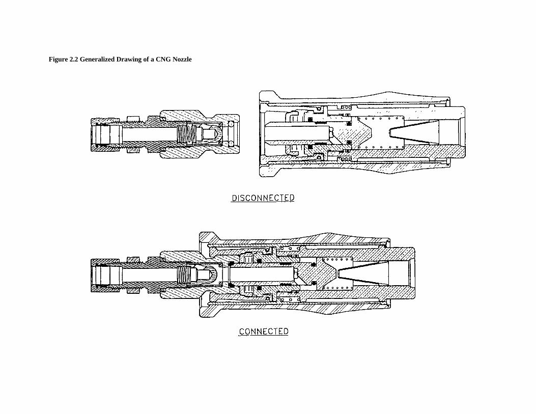
A generalized drawing of a CNG nozzle, including thecommon components as listed above, is shown in Figure2.2. Design, safety, ergonomic, performance, andoperational variations exist by type and manufacturer.
The operation of a nozzle used for CNG consists ofthe following steps:
1. Coupling--Commonly achieved by a ball-lockingdevice inside the nozzle. Steel balls recede into thegroove on the receptacle and are held in place by aretractable sleeve. At least two manufacturers use a"Jaw-lock" technology, whereby a set of radiallyarranged retractable jaws are locked into the recessedpart of the receptacle.
2. Valve Activation--Either as part of, or after, thecoupling process, at least one manually activated valveis opened to enable the passage of natural gas throughthe filler shaft.
• In Type 1 devices, the activation is achieved byturning a serial-action lever that, among otherfunctions, opens the valves.
• In Type 2 and Type 3 devices, the valves areopened through the physical interaction of thenozzle with the receptacle. Most commonly, thenozzle inlet valve is recessed from its seat whenthe filler shaft is pushed back as the nozzle ispushed onto the receptacle.
Nozzle inlet valve activation occurs only if the spacebehind the valve has been depressurized, allowing thevalve to recede from its seat.
3. Fueling--Achieved by activating a control switch orlever on the nozzle (for Type 1), at a 3-way valveupstream from the nozzle (for Type 2), or at thedispenser (for Type 3), which provides the pressure toopen the pressure-activated check valve in thereceptacle. Fueling proceeds until a set pressure isreached on the vehicle or until it is manuallyinterrupted. The fueling process is terminated at thedispenser, where a mechanically or electronicallycontrolled valve is shut. Generally, the flow of gasstops when the pressure in the vehicle is equal to thesupply pressure. The lack of flow activates aflowsensing valve and the dispenser is shut.
4. Depressurization--Achieved according to the nozzledesign.
•• In Types 1 and 2 Nozzles--The hose and thenozzle remain fully pressurized until adepressurization action is initiated. In Type 1nozzles, the nozzle depressurization action isintegral to the disconnecting process (i.e., a singleturn of the handle sequentially depressurizes anddisconnects the nozzle). Type 2 nozzles requireseparate depressurization and disconnect actionsby the operator. The CNG in the hose is isolatedat the dispenser and at the nozzle, but it remainspressurized in both nozzle types.In Type 3 Nozzles--Depressurization is achievedin two stages. First, the hose and the nozzle aredepressurized to inlet pressure14 (commonly 2580psi) at the dispenser. After disconnection of thenozzle, the gas from the nozzle and the mouth ofthe receptacle (now at inlet pressure) is releasedto the atmosphere. A check valve prevents thegas in the hose from being released.
_____________________________________
14 The preferred depressurization system set up for a Type 3 nozzleis to return the pressurized gas to the main gas supply (inlet)system. In practice, this gas is often vented.
Figure 2.1 Example of NGV-1 Receptacle Used in CNG Vehicles
Figure 2.2 Generalized Drawing of a CNG Nozzle
12
5. Decoupling--Achieved by unlocking the retainingballs or the claws and removing the nozzle from thereceptacle.
• Type 1 Nozzles--On one manufacturer's product,a handle is turned to the connect position. Thisaction removes the metal-retaining sleeve fromthe claws. The spring-loaded claws separate fromthe retaining groove on the receptacle, freeing thenozzle and allowing it to be removed. Anothermanufacturer's nozzle operates like a gasolinenozzle. Deactivation of the lever depressurizesthe nozzle and disengages the retaining ballsfrom the retaining groove on the receptacle,freeing the nozzle and allowing it to be removed.
• Type 2 and Type 3 Nozzles--These nozzles aregenerally interchangeable. They have asleevelock mechanism to lock the retaining ballsor jaws into the retaining groove of thereceptacle. Generally, a pull on the sleeve freesthe locking mechanisms and simultaneouslyremoves the nozzle.
Dead Space Volume (Nozzle and Receptacle)
The DSV on the nozzles varies by type andmanufacturer. Generally, Type 1 nozzles have the largestDSV, followed by Type 2 and Type 3. The complexfunctional requirements of the Type 1 nozzle, which housesup to three valves and the mechanisms associated withopening and closing the valves and channeling of thedepressurized gas, requires a larger nozzle and a longerfiller shaft. Type 3 nozzles, which are generally for lighter,slow-fill, applications, are designed for fewer cycles andwith smaller internal components.
The DSV is determined by the length and diameter ofthe filler shaft on the open side of the nozzle inlet valve. InType 1 nozzles, additional DSV is associated with thespace used by the components for integral depressurization.This space may double the DSV associated with the fillershaft. To determine the amount of gas releasable from arefueling operation, two other measurements are needed:the DSV associated with the receptacle and the pressure atwhich the nozzle is disconnected. The latter is of particularrelevance to Type 3 nozzles.
The following DSV estimates are a combination ofinformation supplied by manufacturers and measurementsmade by the authors; they show the approximate range andrelative values for different types of nozzles:
• Type 1--1-10 cm3, depending on manufacturer. Onemanufacturer markets a large, heavy-duty nozzle, thathas approximately a 30-cm DSV.
• Type 2--1-3 cm3, depending on the application and themanufacturer.
• Type 3--0.5-2.0 cm3 when manufactured for use as aType 3 nozzle. For Type 2 devices in Type 3 systems,the DSV is the same as for Type 2 nozzles.
At atmospheric pressure the amount of gas released tothe atmosphere from the DSV is very small. Appendix Awas developed to put the volume of gas released from theDSVs into perspective. However, as DSV and pressureincrease, the amount of gas released to the atmosphereincreases. This increased release is due to three commonsystem design features: incomplete recovery of the residualgas, venting15 of the nozzle only, and venting of the nozzleand the hose:
•• Incomplete Recovery of the Residual Gas—Insystems where the gas is recovered through aconnection to the inlet manifold on the compressor,the high-pressure gas is released from the DSV.However, the DSV will still contain gas at the pressureof the intake manifold. Generally, this pressure is 30to 80 psi, but can be as high as 200 to 400 psi.
•• Venting of the Nozzle Only--In nozzles where theresidual (high-pressure) gas is vented rather thanrecovered (at the inlet manifold of the compressor orotherwise) the amount of gas released from the nozzlemay be 200 to 300 times the amount of gas resident inthe DSV under atmospheric pressure.
•• Venting of the Nozzle and the Hose--In Type 3nozzles, which have the smallest DSV, the amount ofgas released is often much more than indicated by theDSV. In Type 3 applications where the residual(highpressure) gas is vented from the nozzle and thehose, the amount of gas released from the nozzle isdwarfed by the amount of gas released from the hose.
Generally, natural gas recovery through a connectionto the low-pressure side of the intake manifold (i.e.,incomplete recovery of the residual gas) is recommended.This is achievable at a minor cost and system maintenancepenalty. A more costly and a more complex option is todepressurize the nozzles (and, in Type 3 nozzles, includingthe hose) to near atmospheric pressure. Depressurization toatmospheric pressure also increases the risk of introducingair into the fuel system (a potential hazard).
Safety
All nozzles are designed to protect the user from high-pressure releases. The safety features present in all NGV-1nozzles include the following:
• Positive connection before gas flow.____________________________
15 Refers to atmospheric venting.
13
• Difficult to disconnect when pressurized.• Difficult to connect where the nozzle inlet valve
senses back pressure (back pressure can indicate thatvalves upstream may be leaking).
• Automatic check valve activation (nozzle inlet valve)to shut off the flow of fuel on accidental disconnectionfrom the receptacle.
There are some operations-, weight-, and materials-related safety issues that can affect the risk from nozzleusage. In some cases, reducing the DSV may reduce someof the risks. These risk issues include the following:
• Operations--Nozzles depressurized through recoveryto the intake manifold are not fully depressurized.There will be a slight release of some gas fromdisconnection. The risk is small and varies accordingto the amount of gas and the pressure. Decreasing theDSV can reduce or eliminate this safety issue.
• Weight--There is a significant difference in thenozzles' weight. Type 3 nozzles weigh only a few oz.Type 1 nozzles, designed for heavy-duty applications,may weigh up to 7 lb. These heavy nozzles requireheavier hoses and present weight and flexibility issues.Some transit organizations addressed the issue byattaching the nozzle to a counterweight. Reducing theDSV may or may not reduce the weight of thesedevices, but it would not increase their weight.
• Materials--There is no discernible safety-relateddifference among CNG nozzles related to materials.
Performance Specifications
Manufacturer information is not necessarily related touniform performance. The most relevant information isflow rate, measured in standard cubic feet per minute(scfm). Some manufacturers do not provide flow rate. Oneprovides a single (maximum) flow rate for only selectednozzles in the same catalogue. Another provides detailedgraphical information on flow rates at different receiverpressures (the pressure of the system being filled).Maximum flow rates of between 800 scfm for Types 2 and3 nozzles and 5,000 scfm for Type 1 (heavy-dutyapplications) were noted.
Operating time differs by application. A Type 1 or 2nozzle used for public station and fleet applications mayhave frequent, short cycles. This demands assuredconnect/disconnect performance and durability. Type 3devices, in slow-fill applications, may have only one userper day but long operating times. Performancerequirements by use category are as follows:
• Class A Nozzle--High-frequency use, with a cycle lifeof 100,000 connections and disconnections. Thisequates to 100 fills per day for 3 years.
• Class B Nozzle--Medium-frequency use, with a cyclelife of 20,000 connections and disconnections. Thisequates to 10 fills per day for 5 years.
The extent to which each design has been proven toconform to these standards is not clear.
Operational Issues
Operations-related information is not readily available.This is primarily due to sensitivities associated with in-fieldperformance and reliability issues. The following isprovided to indicate the level of information.
Operating and Maintenance Procedures
Of the manufacturer and distributor informationobtained for this digest, material from only onemanufacturer provides written instructions for nozzleselection, installation, and maintenance. These instructionsalso provide the purchaser with warnings and safety-andoperations-related information. This information is notdesigned for the users at the fueling station. However,information from this publication can be adopted andposted at the fueling site. Other organizations haveprovided only sales-related operating information.
Ergonomics
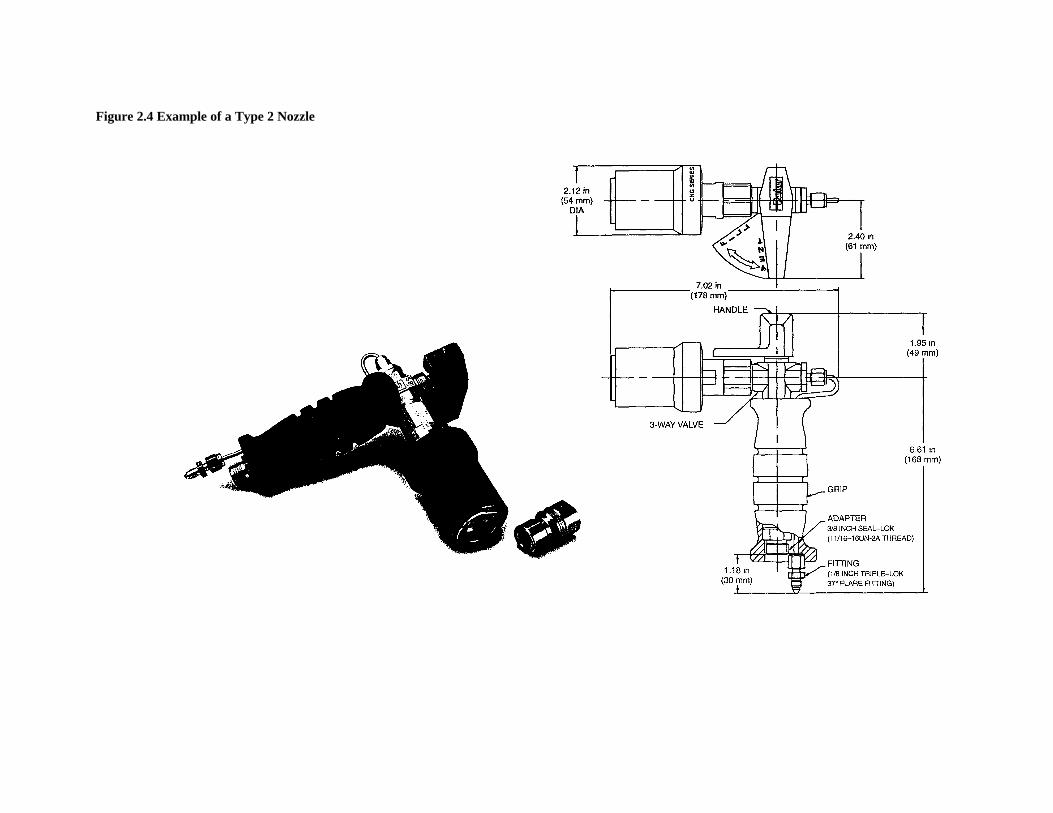
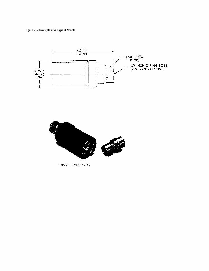
The ergonomics of nozzle use are more a function ofvehicle design and the accessibility of the receptacle thanof nozzle design. With the exception of Type 1 nozzles,nozzle designs are similar. Samples of Type 1 nozzles fromdifferent manufacturers are provided in Figures 2.3.A and2.3.B. An example of a Type 2 nozzle is presented inFigure 2.4. An example of a Type 3 nozzle is presented inFigure 2.5.
One manufacturer markets a Type 1 nozzle with agasoline nozzle design and feel (see Figure 2.3.B). Thisnozzle can be operated with one hand and is designed toconnect and initiate fueling by squeezing a handle. Thesqueeze of the handle initiates several serial operations thatconnect, lock, and (after the lock position is engaged) openthe flow valves. Disconnection is achieved through thereverse sequence of operations. These operations aretransparent to the user; the user only squeezes the handleand attaches the nozzle to the receptacle. This design is notcurrently available for heavy-duty applications.
The only nozzle on the market designed specificallyfor heavy-duty applications is very heavy, weighing severalpounds. Its connection to two rather inflexible hoses(supply and vent), makes it difficult to use. Some sites haveadjusted for this difficulty by attaching the nozzle and hoseassembly to a counterweight suspended from a pulley.
Figure 2.3.A Example of Type 1 Nozzle From Two Manufacturers
Figure 2.3.BExample of Type 1 Nozzle From Two Manufacturers
Figure 2.4 Example of a Type 2 Nozzle
Figure 2.5 Example of a Type 3 Nozzle
18
Reliability
There is little comparative reliability-relatedinformation available. Therefore, comparison of reliabilityby type or by manufacturer is not practical, nor are suchcomparisons pertinent to the DSV issue. The followingfailure modes were noted:
• O-ring deterioration leading to slow leaks and severe leaks;
• Hose/nozzle separation leading to high-pressure leaks (manufacturers claim these leaks generally result fromabuse.);
• Accumulation of foreign matter at the valves preventing a tight seal and resulting in continuous leaks;
• Poor seal because of freeze/thaw deterioration; and• User abuse, such as driving the vehicle over the
hose/nozzle assembly, resulting in the failure of thelocking device, external valve failure (Type 2),internal misalignments, warping of handles, and otherfailures.
This list is not in order of importance or frequency ofoccurrence.
LNG NOZZLES
The estimated 700 LNGVs in the United States arefueled at approximately 20 refueling stations, which arelocated mainly in the South and Southwest.16 LNG isdelivered by truck or rail to cryogenic storage facilities nearthe dispensers. The refueling stations use speciallydesigned pumps to provide flow to the dispensers. Eachrefueling station has at least one fuel dispenser or flowcontrol apparatus, each with one or more LNG nozzles.There are between 50 and 100 LNG nozzles in operation inthe United States; about one-half of these are at transitfacilities.
There are two basic types of onboard fuel systemdesigns that affect the fueling process. One uses a singlenozzle that injects LNG into the fuel tank through asprayer. The spraying action collapses the onboard LNGvapor, reduces the vapor pressure, and permits the liquidfuel to flow from the storage vessel into the onboard fueltank. The second type uses a dual-hose vaporrecovery/liquid delivery system. The removed vapor iseither collapsed in the storage tank, vented, reliquefied,used for on-site applications (e.g., CNG vehicle fuel), orinjected into the natural gas supply system. This systemrequires two nozzles: one for transferring LNG fromstorage to the fuel tank and another for vapor recovery.
______________________________
16 Science Applications International Corporation, estimates,derived from SAIC's 1997 NGV Market Survey.
Description and Features
The nozzle used for the transfer of LNG into thevehicle is a metallic coupling device, containing at leastone check valve to contain and control flow. The nozzle isattached to the end of an insulated pressure hose, which isgenerally attached to a dispenser. In some makeshiftoperations, such as on a trailer or temporary LNG storageor liquefaction facility, the hose is attached to a simple flowcontrol assembly.
Unlike the standards for CNG nozzles, there are noAmerican Gas Association (AGA)/ANSI standardsdefining size, type, function, performance, or other featuresof LNG nozzles or receptacles. The various nozzles, madeby different manufacturers, are not directlyinterchangeable. The following categorization of availableLNG nozzles is based on selected features, not on astandard. (For the convenience of the reader, letters areassigned to distinguish the various types of nozzle designs.)
• Type A--Figure 3.1 is a schematic view of adualaction, radially connected LNG nozzle. It consistsof the tube fitting, valve housing (body), valve handle,collar, collar handles, brace, and seals, bearings, andother fastening and valve activation-relatedcomponents.The active part of the nozzle is the face valve, which ismanually activated to the "open" and "close"positions. An optional nitrogen purge feature is usedto reduce the accumulation of frost on the lockingmechanism and face valve. The nozzle has a high flowrate to minimize fueling time. It is intended primarilyfor use in HDVs by trained fuellers. It is the mostcommonly used LNG nozzle at transit facilities.
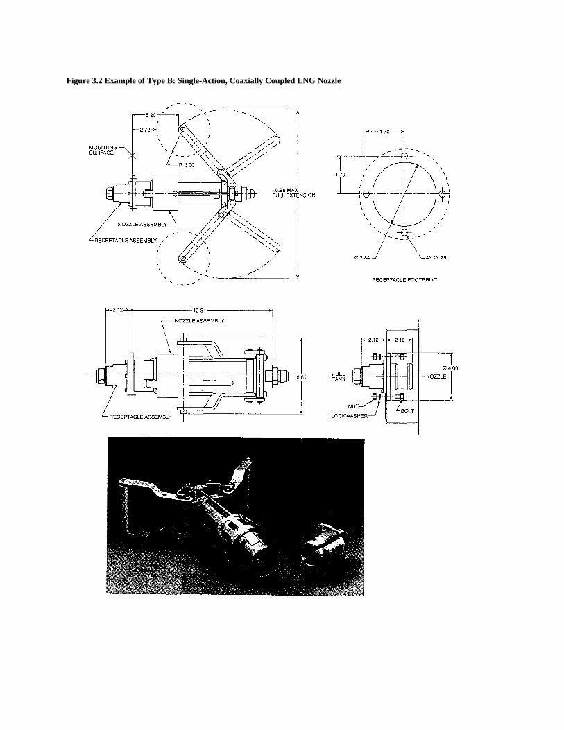
• Type B--Figure 3.2 provides a view of a single-action,coaxially connected LNG nozzle. As shown, thenozzle is intended for use in non-vent systems. Avariation of the design exists in a dual-lineconfiguration for use in vent/fueling systems. Itconsists of a tube fitting that attaches to the LNG hose,valve housing (body), two scissor-like handles, spring-reinforced locking tongues, seals, and other fasteningand valve activation-related components.The active part of the nozzle is the connection-activated check valve. This valve, and a similarreciprocal valve on the receptacle, are activated as partof the coupling process. This is also a high flow-ratenozzle for HDV applications by trained fuellers. It isthe second most commonly used LNG nozzle at transitfacilities.
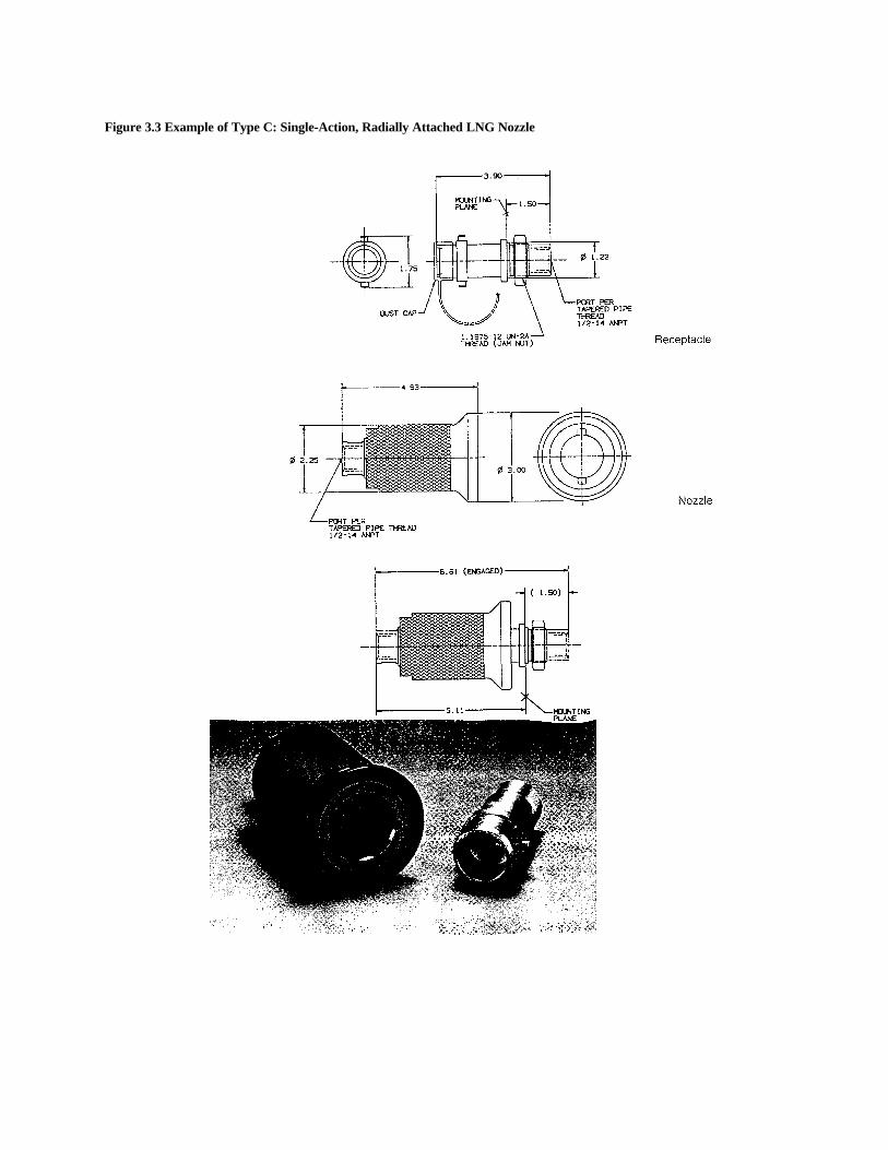
• Type C--Figure 3.3 shows a single-action, radiallyattached LNG nozzle (a hybrid of the Type A and Bnozzles). A radial turn of the nozzle attaches it to thereceptacle and opens the valves on the nozzle and
Figure 3.1 Example of Type A: Dual-Action, Radially-Coupled LNG Nozzle
Figure 3.2 Example of Type B: Single-Action, Coaxially Coupled LNG Nozzle
Figure 3.3 Example of Type C: Single-Action, Radially Attached LNG Nozzle
22
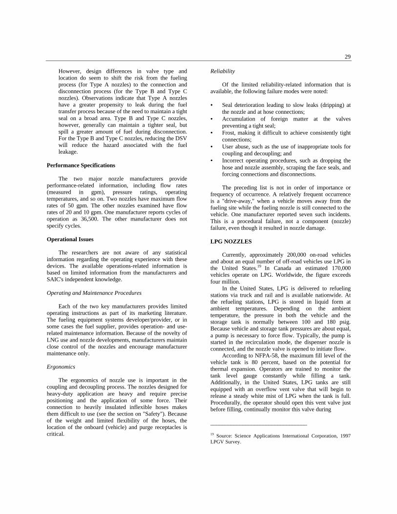
receptacle. The nozzle is designed for non-ventsystems.The internal components and the activation feature ofthe Type C nozzle are similar to those of Type B, butwithout the coaxial attachment and matingmechanism. This type of nozzle is designed forlightand medium-duty vehicles where flow rates of 10gal per minute (gpm) are acceptable.
The development of LNG nozzle technology for use invehicle fueling is primarily a product of U.S. research anddevelopment. Early fueling devices were developed in the1970s. Improvements followed in the late 1980s, whichwere followed by the current family of LNG nozzletechnologies.
Alternative Designs
The literature describes two early alternative systems.The first was used to fuel an experimental aircraft. Aderivative of this technology is shown in Figure 3.4. Thisdevice uses a two-socket coupling to mate with a two-plugreceptacle on the vehicle. The upper line is for vaporrecovery; the lower line is for LNG supply.17
Another nozzle uses a coaxial, bayonet-style couplingfor quick connect/disconnect. The vapor return is in avacuum-jacketed fill hose and surrounds the LNG supplyline. Fueling is initiated through the activation of a checkvalve. Figure 3.5 shows a schematic diagram of thisnozzle.18 These designs saw limited commercial use in the1990s.
At least two LNG nozzle technologies are in the earlystages of development or experimental use. One model wasnot examined or seen by the researchers. Because little isknown about the design, the following detailed informationis provided below, as supplied by the developer:
•• Special Features--Contains two fluid fillings; twoswivels to allow free rotation of the inlet and returnlines for ease of operation; two shear seal valves thatare driven through individual manual buttons; a quick-disconnect nozzle assembly comprising two zero-spill,zero-leak, male quick disconnects and a controlmechanism activated by a button identified as "on"automatically opening flow to the adapter when thetwo are coupled.
•• Construction--Construction materials: stainless steelfluid fitting, nozzle body, and locking arm; Tefloncontrol mechanism, linkage and control circuit, andelastomeric seals.
_________________________________
17 Gas Research Institute, "LNG Vehicle Technology, Economics,and Safety Assessment," Final Report, Chicago, Illinois, February1994 (GRI-94/0051).18 Gas Research Institute, op. cit., February 1994 (GRI-94/0051).
• Physical Features--Weight: less than 12 lb; Size: 4 x5 x 10 in. envelope; fail safe and automatic.
•• Operation--Automatic, single-action connection,dual-line design; sleeve is pulled back uncoupling,insulated to allow glove-free handling.
•• Design Details--"Non-spill," quick-disconnectcouplings designed to enable the user to connect anddisconnect fluid system lines under operatingconditions. Features a flush-face valving design and aninherent free-floating sealed cartridge in the adapterhalf for reliability with zero spillage and zero airinclusion.
•• Safety Features--Zero leakage or spillage if seal"hang-up" (valve closure is independent of sliding sealfriction), zero valve opening until after connectors aremechanically locked together and pressurized, zerospillage on disconnect and zero air inclusion onconnect (zero voids on mating faces).
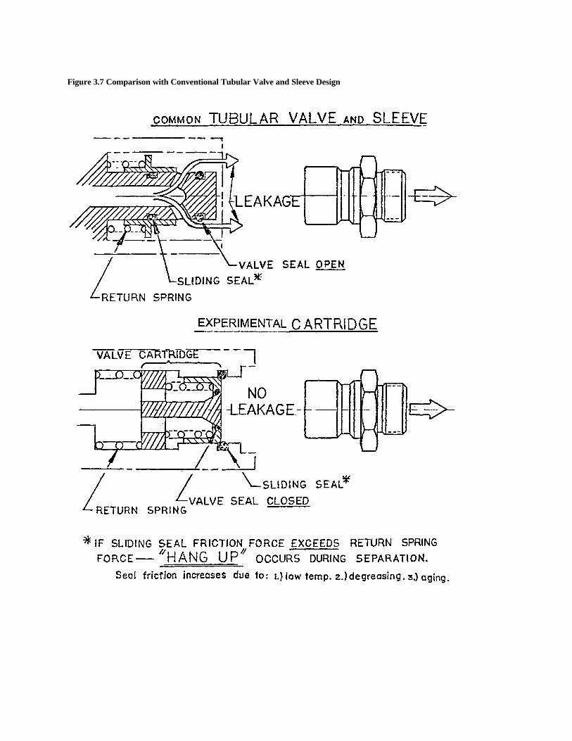
Figure 3.6 illustrates the principle of operation of thistechnology, and Figure 3.7 illustrates a comparison with theconventional tubular valve and sleeve design. The otherexperimental design is shown in Figure 3.8. Theapproximate DSV is between 30 and 35 cm3. (Anadditional 3 to 4 cm3 of DSV is in the receptacle.) The DSVcould be easily reduced to a fraction of its current volume,but not to the 2 cm3 range. The nozzle weighs about 8 lband contains one flow valve in the nozzle and one in thereceptacle. It is a dual-action, radially attached LNGnozzle, with an in-line, manually activated valve. A radialturn of the latch attaches it to the receptacle. Successfulattachment of the nozzle positions a slit on the latch intothe open position, allowing the handle to be pulled and thefuel transfer to begin. The performance parameters of thedevice are not known because of limited use.
Principles of Operation
Because nozzle and receptacle characteristics are notstandardized, there are major operational variations bymanufacturer and type. A general description of theoperation of these devices is provided below. Operationaldifferences among the various devices are provided wherenecessary.
The operation of a nozzle used for LNG consists of thefollowing steps:
1. Coupling--All LNG nozzles require positive couplingbefore fuel transfer. In Type A and Type C nozzles,attachment to the receptacle is achieved through a radiallyactivated locking mechanism. In Type B nozzles, the pushof a single-motion, serial-function handle attaches thenozzle to the receptacle.
Figure 3.4 Two-Socket LNG Nozzle
Figure 3.5 Coaxial, Vacuum-Jacketed LNG Nozzle
Figure 3.6 Principle of Operation
Figure 3.7 Comparison with Conventional Tubular Valve and Sleeve Design
28
2. Valve Activation--Either as part of the coupling processor through a subsequent, separate action, at least onemanually activated valve is opened to allow LNG to passthrough the filler shaft in the nozzle. In Type A nozzles,fuel flow is initiated only after a handle on the nozzle isturned to open a valve. In Type B and Type C nozzles, flowis initiated by pushing a single-motion, serialfunctionhandle (also used to attach the nozzle to the receptacle) toopen the valves on the nozzle and receptacle.
3. Fueling--Fueling is achieved by turning a lever on theType A nozzle or activating the dispenser for the Type Band Type C nozzles. For vent systems, similar activation ofthe vent nozzle is required. Generally, no separateactivation of the vent line at the dispenser is needed. Forvent systems, if the vapor pressure in the fuel tank isgreater than the supply pressure, then pressure reduction,by removal of the LNG vapor, is needed to obtain effectiveflow. Fueling proceeds until a set volume is transferred,until (liquid) LNG is sensed by the vent line, or until flowis manually interrupted. The fueling process is terminatedat the dispenser, where a mechanically or electronicallycontrolled valve is shut. This interrupts the supply of LNGbut does not purge the nozzle or hose.
4. Decoupling--Decoupling is achieved by shutting thevalve (or in two-nozzle systems, the valves) and reversingthe coupling process.
5. Purging and Depressurization--After the supply nozzleis disconnected it may be reconnected to a purge receptacleon the dispenser. The vent line is not purged ordepressurized. If another fueling is planned within a shortperiod of time (a few minutes) purging of the nozzle andhose is not necessary.
Dead Space Volume (Nozzle and Receptacle)
DSV varies by type and manufacturer. Generally,Type A nozzles are designed with a face valve system thatminimizes spillage during decoupling. The manufacturerspecifies a maximum liquid spillage of 2.4 cm3 duringdecoupling (there is no spillage associated with coupling).Type B and Type C designs generally use recessed checkvalves. These devices are specified to have maximumspillage of 5-20 cm3 (of liquid) during decoupling. Thevolume specified depends on the design and size of thenozzle. The nozzles in various stages of development haveDSVs measured at up to 40 cm3.
In operations where fueling is infrequent and thenozzle and hose must be purged, pressurized vapor isvented when the nozzle is decoupled from the purgereceptacle. In two-nozzle systems, the vapor recoverynozzle may contain liquid LNG.
Safety
LNG nozzles are designed to protect the user from thehazards associated with cryogenic liquids, combustiblefuels, and high-pressure releases of combustible gases.Differences among manufacturers and designs have beenobserved. Among the major safety features are thefollowing:
•• Positive connection requirement to initiate andmaintain LNG flow;
•• Automatic check valve activation to shut off the fuelflow if there is accidental disconnection from thereceptacle (Types B and C devices); and
•• Interlocking system to prevent valve from openingwhile the nozzle is not connected and to preventdisconnection while the dispensing valve is open(Type A devices).
Operational requirements specify the use of protectiveclothing, face and eye protection such as goggles, andspecially designed gloves. Fueling with LNG also requiresthe fuellers to be trained.
There are some operations-, weight-, and materials-related safety issues that can affect the risk from nozzleusage. In some cases, reducing the DSV may reduce someof these risks. These risk issues include the following:
•• Operations--Before disconnection from the onboardreceptacle, all LNG supply nozzles containpressurized cryogenic liquid. LNG vapor recoverynozzles are also pressurized and rely on one valve toshut the system. Under certain conditions the vaporrecovery valve may contain cryogenic liquid.Decreasing the DSV can reduce the associated hazard.Other safety issues and hazards, such as poorergonomics associated with the connection anddisconnection process, are not likely to be related tothe DSV.
•• Weight--There are substantial differences in theweight of the nozzles and the weight of the hose andnozzle assembly. Nozzle weight varies between about1 and 8 lb. A closely related issue is the combinedeffect of weight and flexibility. Generally, the heaviernozzles use heavier hoses and present a weight and aflexibility issue, especially in the dual-line systems.System developers have addressed the weight issue byattaching the nozzle to a counterweight or aspringloaded lever that helps to direct the nozzle andhose assembly. Reducing the DSV will probably notreduce the weight of these devices, but it will likelynot increase their weight either.
•• Design--All LNG nozzles are manufactured fromaluminum or special cryogenic steel. Therefore,materials selection is of no particular concern.
29
However, design differences in valve type andlocation do seem to shift the risk from the fuelingprocess (for Type A nozzles) to the connection anddisconnection process (for the Type B and Type Cnozzles). Observations indicate that Type A nozzleshave a greater propensity to leak during the fueltransfer process because of the need to maintain a tightseal on a broad area. Type B and Type C nozzles,however, generally can maintain a tighter seal, butspill a greater amount of fuel during disconnection.For the Type B and Type C nozzles, reducing the DSVwill reduce the hazard associated with the fuelleakage.
Performance Specifications
The two major nozzle manufacturers provideperformance-related information, including flow rates(measured in gpm), pressure ratings, operatingtemperatures, and so on. Two nozzles have maximum flowrates of 50 gpm. The other nozzles examined have flowrates of 20 and 10 gpm. One manufacturer reports cycles ofoperation as 36,500. The other manufacturer does notspecify cycles.
Operational Issues
The researchers are not aware of any statisticalinformation regarding the operating experience with thesedevices. The available operations-related information isbased on limited information from the manufacturers andSAIC's independent knowledge.
Operating and Maintenance Procedures
Each of the two key manufacturers provides limitedoperating instructions as part of its marketing literature.The fueling equipment systems developer/provider, or insome cases the fuel supplier, provides operation- and use-related maintenance information. Because of the novelty ofLNG use and nozzle developments, manufacturers maintainclose control of the nozzles and encourage manufacturermaintenance only.
Ergonomics
The ergonomics of nozzle use is important in thecoupling and decoupling process. The nozzles designed forheavy-duty application are heavy and require precisepositioning and the application of some force. Theirconnection to heavily insulated inflexible hoses makesthem difficult to use (see the section on "Safety"). Becauseof the weight and limited flexibility of the hoses, thelocation of the onboard (vehicle) and purge receptacles iscritical.
Reliability
Of the limited reliability-related information that isavailable, the following failure modes were noted:
•• Seal deterioration leading to slow leaks (dripping) atthe nozzle and at hose connections;
•• Accumulation of foreign matter at the valvespreventing a tight seal;
•• Frost, making it difficult to achieve consistently tightconnections;
•• User abuse, such as the use of inappropriate tools forcoupling and decoupling; and
•• Incorrect operating procedures, such as dropping thehose and nozzle assembly, scraping the face seals, andforcing connections and disconnections.
The preceding list is not in order of importance orfrequency of occurrence. A relatively frequent occurrenceis a "drive-away," when a vehicle moves away from thefueling site while the fueling nozzle is still connected to thevehicle. One manufacturer reported seven such incidents.This is a procedural failure, not a component (nozzle)failure, even though it resulted in nozzle damage.
LPG NOZZLES
Currently, approximately 200,000 on-road vehiclesand about an equal number of off-road vehicles use LPG inthe United States.19 In Canada an estimated 170,000vehicles operate on LPG. Worldwide, the figure exceedsfour million.
In the United States, LPG is delivered to refuelingstations via truck and rail and is available nationwide. Atthe refueling stations, LPG is stored in liquid form atambient temperatures. Depending on the ambienttemperature, the pressure in both the vehicle and thestorage tank is normally between 100 and 180 psig.Because vehicle and storage tank pressures are about equal,a pump is necessary to force flow. Typically, the pump isstarted in the recirculation mode, the dispenser nozzle isconnected, and the nozzle valve is opened to initiate flow.
According to NFPA-58, the maximum fill level of thevehicle tank is 80 percent, based on the potential forthermal expansion. Operators are trained to monitor thetank level gauge constantly while filling a tank.Additionally, in the United States, LPG tanks are stillequipped with an overflow vent valve that will begin torelease a steady white mist of LPG when the tank is full.Procedurally, the operator should open this vent valve justbefore filling, continually monitor this valve during
_________________________________
19 Source: Science Applications International Corporation, 1997LPGV Survey.
30
filling, and use the existence of flow from this valve as theprimary indication about when to stop filling. Then theoperator should close the bleed valve, and recap the mainfill valve. Newer vehicle tanks are equipped with float-operated stop valves that stop the filling process when thetank is 80 percent full. In other countries, such as Australia,equipping LPG vehicles (LPGVs) with overflow ventvalves (commonly known as "spit valves") is specificallybanned by relevant standards. In these countries automaticfill limiting (AFL) valves are used to automaticallyinterrupt fuel transfer when the fuel level in the LPG tankreaches 80 percent of capacity.
LPG automobile tanks are constructed from carbonsteel to meet the Boiler and Pressure Vessel Code of theAmerican Society of Mechanical Engineers (ASME). Astudy conducted by the Research Institute for RoadVehicles TNO of Delft in the Netherlands concluded thatvehicles fueled by LPG are safer in crashes thangasolinefueled vehicles.
This section provides a summary of informationcollected and planned to be collected on LPG nozzles.
Description and Features
Two technologies for nozzles are used in the UnitedStates. For simplicity, they will be called basic nozzles andenhanced nozzles in this digest. Basic nozzles have anoperator and stem, a ball or globe, a seat, and a body.Enhanced nozzles have additional moving parts and flowpaths to increase safety and reduce emissions.
Principles of Operation
Several aspects of refueling are common to bothtechnologies. The onboard tank typically has a fuelcapacity of 30-70 gal. NFPA code requires limiting theliquid volume in a tank to 80 percent of its rated watercapacity to allow for LPG expansion. Depending on the filllevel and ambient temperature, the pressure in the tankvaries between 100 and 180 psig. The tanks include asingle relief valve set to lift at 312 psig. The relief valve isdesigned to lift when a correctly filled tank is exposed to afire or if a completely full tank is heated.
In the United States, an LPGV has a standard, malefueling receptacle. A cap is threaded onto the receptacle toprotect the mating surface and gasket when refueling is notin progress. The exterior wall of the receptacle protects thegasketed mating surface. A valve (called a filler valve) isfound just below the mating surface to keep the tank fromleaking. The filler valve is normally a check valve, butoccasionally, an operable check valve or an isolation valvemay be used.
When preparing to refuel a vehicle, the nozzle collar isthreaded onto the receptacle. The collar is made of spark-free brass or aluminum and is operated easily by
hand. As the collar is tightened, the nose piece of thenozzle is drawn into the mating surface of the filler valve.When the refueling connection is completed, the vent valveon the vehicle and, if necessary, a filler valve are opened,the dispensing system is started, and the nozzle valve isopened.
Basic Nozzles
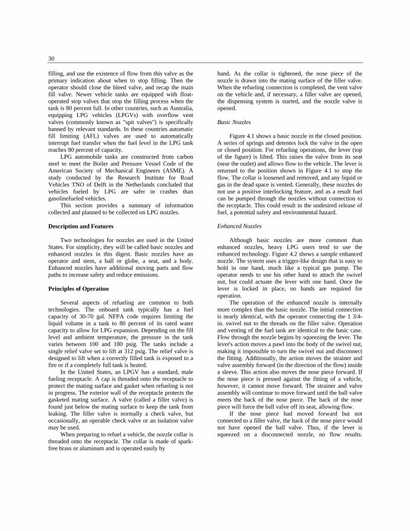
Figure 4.1 shows a basic nozzle in the closed position.A series of springs and detentes lock the valve in the openor closed position. For refueling operations, the lever (topof the figure) is lifted. This raises the valve from its seat(near the outlet) and allows flow to the vehicle. The lever isreturned to the position shown in Figure 4.1 to stop theflow. The collar is loosened and removed, and any liquid orgas in the dead space is vented. Generally, these nozzles donot use a positive interlocking feature, and as a result fuelcan be pumped through the nozzles without connection tothe receptacle. This could result in the undesired release offuel, a potential safety and environmental hazard.
Enhanced Nozzles
Although basic nozzles are more common thanenhanced nozzles, heavy LPG users tend to use theenhanced technology. Figure 4.2 shows a sample enhancednozzle. The system uses a trigger-like design that is easy tohold in one hand, much like a typical gas pump. Theoperator needs to use his other hand to attach the swivelnut, but could actuate the lever with one hand. Once thelever is locked in place, no hands are required foroperation.
The operation of the enhanced nozzle is internallymore complex than the basic nozzle. The initial connectionis nearly identical, with the operator connecting the 1 3/4-in. swivel nut to the threads on the filler valve. Operationand venting of the fuel tank are identical to the basic case.Flow through the nozzle begins by squeezing the lever. Thelever's action moves a pawl into the body of the swivel nut,making it impossible to turn the swivel nut and disconnectthe fitting. Additionally, the action moves the strainer andvalve assembly forward (in the direction of the flow) insidea sleeve. This action also moves the nose piece forward. Ifthe nose piece is pressed against the fitting of a vehicle,however, it cannot move forward. The strainer and valveassembly will continue to move forward until the ball valvemeets the back of the nose piece. The back of the nosepiece will force the ball valve off its seat, allowing flow.
If the nose piece had moved forward but notconnected to a filler valve, the back of the nose piece wouldnot have opened the ball valve. Thus, if the lever issqueezed on a disconnected nozzle, no flow results.
Figure 4.1 Example of Basic LPG Nozzle (Shown in Closed Position)
33
When the lever is released, the large spring moves thevalve and strainer assembly back into its original place. Thevalve spring reseats the ball valve and stops fuel flow. Thepawl is removed from the swivel nut so the fitting can bedisconnected. The LPG in the nose piece and filler valve isvented.
Dead Space Volume (Nozzle and Receptacle)
The enhanced nozzles are designed to reduce DSV.For example, one nozzle is designed so that 1.9 cm3 isdischarged from the nozzle on release of the lever. Theother enhanced nozzles have DSVs of similar size.Although independent measurements were not conductedas part of this study, the basic nozzle technology has about2 to 3 times more DSV than the enhanced nozzle.
The nozzle DSV might not be the major issueconcerning LPG releases. The receptacle (filler valveassembly) appears to have a widely varying DSV, generallymuch larger than the nozzle DSV. Additionally, normaltank filling procedures include filling a vented tank until avisible white mist (LPG) comes from the tank. These twoissues need further investigation.
Safety
LPG is typically stored at moderate pressures andambient temperatures. Therefore, if gas is released, thepressure-related energy could cause life-threateninginjuries, but this is unlikely. Small leaks from the nozzlecould cause localized skin damage, but not the severe burnsthat LNG can cause. Unlike gasoline, ethanol, andmethanol, LPG is nontoxic. NFPA-58 requires protectiveequipment because of the potential for cold burns.However, in other countries, where self-serve LPG fuelingis available, equipment is designed to be safer and simplerto operate, requiring no protective gloves during refueling.
Fueling System
Several operational and design aspects affect thesafety of LPG fueling systems:
•• Location of storage tanks--Transit facilities designedfor fleet use of LPG normally have the storage tankremotely placed from the dispenser. This fits thetraffic patterns and allows for an uncluttered fuelisland. The pumps and piping associated with thestorage add some risk to the facility. However, aremote location makes it unlikely that a leak willcontact an ignition source.
•• Location of the dispenser--Transit facilities designedfor LPG vehicles require the dispenser to be in afueling and servicing island. This reduces the numberof bus moves necessary for daily servicing. That
island would likely already have diesel and gasolinedispensers. The addition of a heavier-than-air gaseousfuel to an area that already handles liquid fuel shouldnot be a major safety issue. Service islands at transitfacilities are open at least on two sides, and typicallyon three sides, and are covered by a canopy. Thus,even a light wind will move heavy LPG vapors from asmall leak away from the vehicles before they reachflammable concentration.
Nozzles
All nozzles are designed to protect the user from thehazards of high-pressure releases. However, there aresignificant differences between the basic and enhancednozzle technologies. One enhanced nozzle manufacturerdescribes the following features:
•• Cannot discharge LPG to the atmosphere and must beconnected to a filler valve to allow product flow;
•• Cannot be disconnected from its filler valve while thelever is held in the open position (product flowing),thereby avoiding accidental gas discharge; and
•• Plastic O-ring, securely housed in nose piece,positively seals to its mating filler valve even if theadaptor gasket is missing.
The basic nozzle, as shown in Figure 4.1, will allowflow any time it is operated. Additionally, the nozzle couldbe disconnected while flow is in progress.
Potential for Accidental Release
The most likely way for a large LPG release to occurwould be for a vehicle to drive off while refueling. Somevehicles are equipped with electrical interlocks to preventsuch an event from occurring. Some dispensers in theUnited States are equipped with breakaway check valvesthat prevent continuous releases if the dispenser hosebreaks. However, because fueling is often performed atLPG facilities that are not designed specifically for vehiclerefueling, these sites rarely incorporate breakaway systems,even though NFPA-58 3-9.4.5 specifies the need to install alisted emergency breakaway device designed to retainliquid on both sides of the breakaway point. Also,commonly, the vehicles do not use refueling shutoffswitches to disable the engine. Reports of drive-aways arecommon, but there are no statistics available on thefrequency or severity of these incidents. In Australia,sophisticated breakaway technologies are used thatsignificantly limit the release of LPG in a drive-awaysituation and further limit fuel release during thereconnection of the hose to the breakaway valve.
Because LPG operates at moderate pressures, thepotential for large releases from the nozzle area is small.
34
Even if the nozzle sticks open, or if an O-ring or other softseal fails, the leak rates are small. In Corpus Christi,operators have emergency shutdown abilities at thedispenser, at the storage tank, and at several points aroundthe fueling canopy. They are trained to shut down thesystem if they smell the odorant or suspect leakage.
Operational Issues
LPG fueling is different from other fueling operationscommonly used in the transit industry in that it requires theoperator to observe the filling of the tank directly. As theuse of electronic controls increases, systems will allowoperators to fuel without observing the fueling activity.Typically, dispensing equipment for vehicle servicingfacilities consists of one or several storage tanks, a 20-gpmpump, a meter, and a hose/nozzle assembly.
The business approach used by LPG supplycompanies is an important factor in determining thedirection of LPG nozzle developments. Supply companiestypically provide LPG refueling stations (valued at $3,000to $5,000) to customers (i.e., gas stations, fleets). Thecustomer is required to provide a concrete pad; electricalpower and ground; and barriers, fences, fire extinguishers,and signs required by the NFPA and the local fire marshal.The supply company supplies between one and fourstandard 1,000-gal tanks, a pump (typically 20 gpm), atotalizing meter, a basic nozzle, and associated pipes,valves, and supports. The supply company charges amaintenance fee for the equipment, which includes allpreventive and corrective maintenance, as well as periodicreplacement (3 to 5 years) of LPG nozzles.
The system typically provided by supply companieslooks like an industrial facility. The pipes, valves, pump,and meter are exposed. Typically, local governmentsrequire vegetation or walls to screen this hardware fromview. The same components can be enclosed in a dispenserthat looks much like a common gas pump. Clean FuelingTechnologies provides one such device. Dispensers aretypically equipped with an enhanced nozzle. LPG systemswith dispensers cost two to three times as much as standardsystems. However, the increased cost is not generallydriven by the enhanced nozzle, which typically adds only afew hundred dollars.
SAIC also observed fueling at a public LPG fuelingstation in Fairfax, Virginia. The station is set up as a publicstation and fuels smaller vehicles (cars, small trucks, andvans). The operation is performed by a fueller. The fuellerhas three nozzles for different receptacles, including onefor filling utility tanks (e.g., barbecues).
Operating and Maintenance Procedures
When an LPG fuel supply company installs oroperates an LPG fill station, it typically provides extensive
operations, maintenance, and safety training, and offersongoing training. Design and operational safety isaddressed in NFPA-58, "Standard for the Storage andHandling of Liquefied Petroleum Gases." Additionally,they describe the procedures for operation of theequipment. The procedures are simple enough that they arelearned and generally adhered to after an operator hasreviewed them and operated the station several times
According to NFPA-58, the maximum fill level of thevehicle tank is 80 percent. Operators are trained to monitorthe tank level constantly while filling a tank. Additionally,the tanks are provided with an overflow vent valve thatreleases a steady white mist of LPG when the tank is full.Procedurally, the operator should open the vent valve justbefore filling, monitor it during filling, and use the start offlow from the valve as the indicator to stop filling. Then theoperator should close the bleed valve and recap the mainfill valve. Newer vehicle tanks are equipped with float-operated stop valves that stop the filling process when thetank is 80 percent full. Gloves and face shields should beworn when handling LPG, but these rules are commonlyignored.
Ergonomics
According to several individuals in the LPG industry,ergonomics, not safety or reliability, is the main reasoncompanies choose the more expensive, enhanced nozzle.However, manufacturers indicate that where self-serverefueling is permitted, safety and reliability, as well as easeof operations (as differentiated from strict ergonomics) areof paramount importance. Most nozzles that use the basictechnology are heavy and poorly balanced. The basicnozzle requires two hands to open or close and may bedifficult for operators who are unaccustomed to operatingvalves. The enhanced nozzles look and feel like self-servicegasoline nozzles and incorporate the familiar(gasolinenozzle) look and feel.
Reliability
No quantitative information on reliability wasavailable. However, a supply company reports that thebasic nozzles require an overhaul after 2 to 5 years ofservice. Nozzles identical to those used for vehiclerefueling are on the end of all truck-mounted hoses. Thesetrucks service home and small commercial LPG systems.Although the nozzles are not used as frequently as nozzlesat a busy refueling station, they are pulled to all locationsand are not protected from the environment.
Operators of the fueling station are very sensitive tothese problems. Historically, LPG supplies are very clean.Suppliers are careful not to introduce dirt or grit whenfilling LPG storage tanks. Dispenser and nozzle
35
maintenance activities are the most likely to introducesmall amounts of foreign material into the system.
The following problems could be caused by foreignmatter:
•• Low flow due to foreign matter in the strainer;•• The nozzle swivel nut will not rotate because of matter
between the nut and slide sleeve;•• The nozzle will not connect to the filler valve because
of foreign matter caked on the filler valves;•• The nozzle remains open when the lever is released
because of foreign matter between the nozzle valveassembly and the slide sleeve;
•• The nozzle leaks when connected to a filler valve(when the lever is operated) because of foreignmaterial on the nose piece face or filler valve gaskets.
Occasionally, basic nozzles develop small leaks.Leaks are detected by smell and usually repaired byreplacing non-metallic internal parts (sometimes called"software"). LPG does not have a tendency to cut metalsurfaces. If the software replacements become morefrequent, maintenance personnel assume that the metalsurfaces are degraded. The components are replaced withlike components and sent to vendors or machine shops forreconditioning.
No information is available on the reliability of themore complex enhanced nozzles. However, their valveshave more potential for spring wear problems and areexpected to require more maintenance.
The maintenance manual of one enhanced nozzlestates that the nozzle is sensitive to foreign matter (i.e.,sand, dirt, and grit) in the flow paths. Other maintenanceand reliability issues generally involve small leaks. Leaksoccasionally occur at the inlet swivel joint and the nozzlearea. The inlet swivel consists of an external swivel bodythat is sealed to the nozzle body and an internal body that isconnected to the incoming pipe. Few problems areexpected from the seal between the external swivel andnozzle body because it is locked in place by a lockingscrew. However, relative motion between the external andinternal bodies causes the seal between these two bodies todegrade and eventually leak. Replacement is a standardmaintenance action.
Nozzle area leaks that occur when the nozzle is notconnected to a vehicle come from the main valve assembly.Likely causes are valve (ball) damage, seat damage, andbody leaks due to the assembly coming loose or Oringdeterioration. The root causes are normally wear and tear orforeign matter. The correction is replacement of internalparts with factory-supplied repair kits.
When the fueling operation begins, the sealingsurfaces exposed to fuel pressure change from the mainvalve to the filler valve gasket, main valve assembly seal,and the nose piece O-ring. These seals and gaskets requireoccasional maintenance. After the lever is released, the
pressure from the gas in the dead space is released from theinternals to the swivel nut lip seals. If these seals allowexcessive blowback, they must be replaced.
The nozzle is threaded onto 1/2-in. or 3/4-in. pipe.Because the hose is flexible and the nozzle has a swiveljoint, there is little stress on the threaded connection. Noproblems are normally expected from the threadedconnection.
FINDINGS
In this project, CNG, LNG, and LPG nozzles werereviewed for all types of vehicles. The review coveredlight-duty nozzles (even though the focus of the digest is ontransit bus refueling) because the use of heavy-duty nozzlesis limited and because there is a direct relationship betweenthe technologies used for LDVs and HDVs. Additionally,many transit facilities that made the capital investment intoalternate fuel-dispensing equipment for HDVs also havesome LDVs operating on the same alternative fuel. Thetechnological issue of greatest relevance is fuel loss fromthe coupling and decoupling processes. The findings arepresented by fuel type and relate to all applications unlessotherwise specified.
CNG Nozzles
CNG nozzles used for light-duty applications arecommercially available with DSV of less than 2 cm3. Onlyone commercially available CNG nozzle is specificallydesigned and used for heavy-duty application.
Comparative Status
CNG nozzles release gaseous fuel. Recovery duringdepressurization makes releases from CNG nozzlesrelatively insignificant. DSVs vary from less than 1 cm3 to30 cm3, as follows:
•• Type 1: 1 to 10 cm3 (one nozzle has 30 cm3)•• Type 2: 1 to 3 cm3
•• Type 3:0.5 to 2 cm3
The federal standard (for LDVs) is 1.2 g released perdisconnection. Existing fueling systems can be designed todepressurize the DSV to near atmospheric pressure, todepressurize the DSV to moderate pressure by venting gasto the compressor intake or to the service header, or to ventfull operation pressure gas to the atmosphere. The DSVsthat would meet the federal standards are summarizedbelow, organized by release pressure:
•• Release at atmospheric pressures--A fullyrecuperative system could conceivably depressurizethe DSV to atmospheric pressure. Under theseoperating
36
conditions, a nozzle with a DSV of 1,700 cm3 wouldcomply with the federal standard. However, we knowof no facilities that depressurize their nozzles toatmospheric pressures without venting.Depressurization and recovery generally leave thenozzle at the natural gas intake or service pressure.
•• Release at intake or service pressure (defined hereas 50 psi)--If the DSV pressure were lowered to thispoint, a 500 cm3 DSV would comply with thestandard. Most transit CNG fueling facilities recoverthe nozzle overpressure in this form. However, a fewstill vent the content of their nozzles to theatmosphere.
•• Venting operating pressure gas to the atmosphere--If a DSV at full system pressure of 3,000 psi to 3,600psi were vented to the atmosphere, the maximumnozzle DSV that would meet the federal standardwould be 6 cm3. This estimate would vary by a fewcubic centimeters for higher or lower pressuresystems. Only a few CNG transit facilities vent or failto recover any of the CNG from the nozzle. These arethe smaller CNG transit facilities, which operate a fewbuses and commonly do not use the heavy-dutynozzles.
From the above calculations, it is clear that as long asthe fueling system is designed to vent gas at moderatepressure, all CNG nozzles easily comply with this standard.Nozzles in fueling systems that vent all the gas to theenvironment are releasing amounts approximatelyequivalent to the standard. More precise calculations wouldhave to be performed to verify compliance.
In terms of fuel used and fuel lost, a heavy-dutynozzle transfers 5 to 10 times more fuel per fueling into aHDV (up to 16,000 scf for a transit bus) than a light-dutynozzle into a LDV (1,500 to 2,000 scf for cars, vans, andlight-duty trucks). On this basis, heavy-duty nozzles emitfuel in about the same proportion as light-duty nozzles.
Developmental Status
The CNG nozzle evolved from the couplingtechnology. Until the promulgation of the EPA regulations,there was no need to focus on controlling emissions fromthe connection and disconnection processes. However, theinherent need for depressurization of the nozzle beforedisconnection makes the fuel control issue less a matter ofnozzle design and more a matter of system configuration(i.e., venting versus recovery).
Nozzle Redesign Options
Recovery of vented fuel can reduce the amount of fuelloss by about 99 percent. This applies to both heavy-
and light-duty nozzle and vehicle systems and could beaccomplished with available but not uniformlyimplemented technologies.
Non-nozzle-related system improvements, specificallydepressurization and recovery to atmospheric (rather thanintake) pressure, can further reduce fuel emissions fromCNG nozzles. This option requires the installation of activeor passive recuperators. Depressurization to levels belowatmospheric pressure to recover all of the natural gas in theDSV is not recommended, and the hazards associated withair intrusion because the cost/benefit trade-offs are notfavorable.
For Type 2 and Type 3 nozzles, there are simpledesigns to reduce the DSV. These involve moving the fuelcontrol valve closer to the receptacle and possibly reducingthe diameter of the fuel shaft. For existing heavyduty (Type1) nozzles, redesign is more complex because of theinternal arrangement of components, including multiplevalves. Such a redesign is estimated to cost approximately$30,000, which includes a $10,000 mandatory testing fee.In absolute terms, or compared to the cost of developing acommercial product, these costs are not significant.However, for a product that is currently sold at rates ofseveral dozen per year, the cost is significant and wouldmarkedly affect the nozzle's retail price.
One manufacturer has stated its intention to increasethe throughput of its light-duty nozzle to qualify it as aheavy-duty nozzle. SAIC estimates that the DSV of thisnozzle would be only 3-6 cm3. This nozzle is not yetavailable for review.
Other nozzle designs are possible, including the use ofdifferent types of valves. However, radical changes wouldlikely require the redesign of the receptacle and could resultin fuel transfer-related fuel losses and other issues. Yet, thedevelopment of nozzles with zero or nearzero losses aretechnically possible and may be economically attractivebecause such nozzles would not need to have the fuelrecovery function.
Findings
Summary findings for CNG nozzle design are asfollows:
•• Redesigning existing CNG nozzles to reduceemissions from the decoupling operation is possiblebut not recommended because CNG nozzles alreadymeet or exceed the requirements of the newlyimplemented emission regulations. This is true fornozzles used for both LDVs and HDVs and even insome cases where the fuel is not recovered (i.e.,vented to the atmosphere).
•• Significant fuel loss reductions are achievable throughfuel recovery. Several states and technicalspecification
37
require such recoveries. However, these specificationsare not universally followed. The use of fuel recoveryon a widespread basis would make CNG emissionsfrom the nozzle connection and disconnectionprocesses relatively insignificant (see Appendix A)compared with losses from other sources andcompared with those of other fuels.
•• More radical redesigns, to offer zero or near-zeroemissions, should be allowed to and may evolvethrough the market forces.
LNG Nozzles
Unlike CNG nozzles, most LNG nozzles are suitablefor heavy-duty applications. At least one LNG nozzledesigned specifically for heavy-duty applications has aDSV of 2.4 cm3.
Comparative Status
The fuel contained in the DSV of an LNG supplynozzle is usually in liquid form. On release, the LNGquickly gasifies and may be detected through the resultantvapor cloud (the vapor cloud is water vapor). In a dualhosevapor recovery/liquid delivery system, the vapor recoverynozzle generally should not contain LNG. The size of therelease varies by type and size as discussed in the sectionon "LNG Nozzles" (page 18). The total fuel released in aconnection and disconnection operation includes liquidlosses from the supply nozzle DSV after LNG transfer, pluslosses from the nozzle DSV after vapor recovery, plusvapor losses (from the DSV only) after disconnection fromhose purging operation. The liquid release constitutes morethan 95 percent of the released fuel. Depressurization of theLNG nozzles, with recovery, is not practiced but ispossible.
•• Type 1: 2.4 to 10 cm3
•• Type 2: 5 to 20 cm3
•• Type 3: 5 to 20 cm3
As for CNG, the federal standard (for LDVs) will be1.2 g released per disconnection. Existing nozzles releasefrom 1 to 5 g per disconnection. Precise calculations thatinclude the receptacle DSV may show that no systems meetthe federal standards. Clearly, these releases are muchhigher than for CNG operations. Some LNG nozzles wouldneed significant modifications to meet federal standards forLDVs.
As in CNG operations, a heavy-duty nozzle transfers 5to 10 times more fuel per fueling into a HDV (up to 150 galfor a transit bus) than a light-duty nozzle into a LDV (20 to30 gal for cars, vans, and light-duty trucks).
Development Status
LNG nozzles are still in the development stage. Thereare two LNG nozzle manufacturers that have severalnozzles in production and in use on a commercial scale.Two other manufacturers each have built one nozzle andhave used them in limited commercial applications. Thereare also two developers that each have a nozzle in thedevelopment stage. However, the market for these devicesis limited and growing slowly. For the near term, themarket may not be able to support more than severalmanufacturers. Consolidation of the industry is likely.
Existing nozzle technology evolved from thecryogenic technologies, aircraft and spacecraft fuelingtechnologies, and entrepreneurial development projects.The designs have focused on safety, throughput, reliability,and minimization of fuel transfer losses. Although one ofthe nozzles has a relatively small DSV, there has beenregulatory reason to focus on controlling fuel losses duringconnection and disconnection.
Nozzle Redesign Options
By using readily available fuel recovery technologysimilar to that used in CNG nozzles, LNG fuel losses couldbe reduced by about 99 percent. However, this optionwould require further research, development, and testing.The following section on "LNG Vapor Recovery from theDSV" contains a more detailed discussion of this option.
For Type B and Type C nozzles, redesign options toreduce the DSV are relatively simple. As with CNGnozzles, these redesigns involve moving the fuel controlvalve closer to the receptacle and possibly reducing thediameter of the fuel shaft. One concurrent nozzle designhas a small DSV and is effective in minimizing connectionand disconnection losses.
Radical changes would likely require the redesign ofthe receptacle and could result in fuel transfer losses andother issues. Unlike CNG, however, there are nostandardized receptacles and little chance of suchstandardization occurring in the near future. This leavesroom for the introduction of new and potentially moreeffective nozzles, including the possibility of zero- or near-zero-loss nozzles. A review of this option indicates thatthere are no insurmountable technical barriers to thedevelopment of such a nozzle. Indeed, one manufacturer ofan existing heavy-duty nozzle claims a 2.4 cm3 DSV.Because this is only marginally larger than the requirementfor light-duty LPG nozzles, it is clear that low-losstechnology is feasible. For other manufacturers, however,the absence of a requirement to depressurize and recoverthe fuel from LNG nozzles suggests that
38
there is no economic justification for widespreadtechnology development.
LNG Vapor Recovery from the DSV
During refuelings, LNG is transferred in liquid form atelevated pressures. Following disconnection of the LNGnozzle, LNG is released from the dead space, whichquickly flashes to vapor and dissipates. The most feasibleapproaches for recovering this gas would take advantage ofthis flashing and use it as a motive force to recover most ofthe gas.
Flashing of the LNG contained in the DSV of an LNGnozzle could generate sufficient pressure to permitreinjection of the fuel into the storage tank. Off-the-shelftechnology is available to test and verify the operability andpracticality of this direct (passive) recirculation concept.The introduction of a recovery tube into the DSV and amanually operated external valve could be a simple andinexpensive way to accomplish direct recirculationrecovery. This system would operationally resemble theType 2 CNG nozzle. If it proves practical, the configurationof this system would resemble that of a CNG fuel recoverysystem. However, it is not clear that the flash rate issuitable for removing the LNG in a timely manner.
The recovered LNG (in gas form) could be disposedof by injecting it into the local gas mains, storing it inretainer tanks, or recirculating it into the LNG supply tanksor into the inlets to running compressors. The lowestpressure portion of a city gas main operates at a few poundsper square inch above atmospheric pressure, which is idealfor recovery. Retainer tanks may be a costly option becausea compressor or liquefaction system would need to beinstalled to remove the accumulated vapors from the tankto keep the pressure low. On-site liquefiers would makethis option expensive.
If the flash time is not acceptable, active recoveryusing a recuperation system may need to be considered.SAIC roughly estimated the cost of piping, compressors,mounting, and controls necessary to implement an activeLNG recovery system. The estimated developmental costsare as follows:
•• System Development Costs--$10,000 to $20,000 foreach manufacturer;
•• Nozzle Development Costs--Roughly $10,000 foreach manufacturer;
•• Main Recuperating Equipment--Between $10,000and $25,000 (per station);
•• Site Specific Design Charges--Between $2,000 to$5,000, depending on the physical layout of thefacility and whether it is a new facility or a backfit;and
•• Nozzle Assembly Costs--Roughly $1,000 to $3,000per nozzle assembly.
These estimates assume only a few system sales byeach manufacturer (or system integrator). As a result,system and nozzle development costs would be passed onto only a few users during the cost recovery period(assumed to be 3 years). SAIC also estimates that ifmanufacturers incorporated the recovery valve into thenozzles it would add 25 percent to 50 percent to the cost ofthe current LNG nozzles. However, an active recoverysystem would add only marginally to the cost of an LNGfueling station, which could cost several million dollars.
There is no financial incentive to recover fuel from thedead space. The only reason a recovery system would beimplemented is to meet a regulatory requirement. Thecontinued effort to build reliable LNG nozzles withminimum DSV is a more cost-effective way to reduceemissions than the implementation of an LNG recoverysystem.
Findings
Summary findings for LNG nozzles are as follows:
•• Heavy-duty LNG nozzles are in common use with lowfueling-related losses from a 2.4 cm3 DSV.
•• Another manufacturer reports the development of alow-emission nozzle.
•• Further fuel loss reductions of more than 99 percentare achievable through nozzle depressurization andfuel recovery, a potentially expensive fuel recoveryoption.
•• It is unlikely that any manufacturer will voluntarilyimplement the fuel recovery option because of thecosts associated with such changes, and becauseexisting nozzles meet or can be readily modified tomeet emission regulations.
•• Because of the anticipated frequency of fuelingactivities at LNG transit facilities, and the potential ofindoor LNG fueling, transit facilities may voluntarilyspecify and use fuel recovery as part of their LNGfueling system. Therefore, market forces may lead tothe adoption of LNG recovery systems, wherenecessary.
LPG Nozzles
There are many types and vintages of LPG nozzles inuse in the United States and the rest of world. Unlike LNG,LPG is used predominantly in LDVs. As a result, nozzledevelopments are targeted to that market. Several nozzledesigns already have a less than 2.0 cm3 DSV. Few LPGnozzles were found for heavy-duty applications. Thesewere noted to have DSVs several times the regulatedvolume of the light-duty nozzles. A manufacturerdeveloping a new heavy-duty nozzle indicated that the newnozzle will need to incorporate a
39
DSV that is larger then the 2.0 cm3 volume allowed forsmall vehicular use. Discussions and visits with LPGnozzle manufacturers did not reveal any efforts to reducethe DSV in heavy-duty nozzles. This is due to the limitednumber of nozzles used in heavy-duty vehicle applications,and because there are no regulations that require nozzlemanufacturers or users to limit the DSV or associatedemissions from these types of nozzles.
Status
As in the LNG nozzles, the fuel contained in the DSVof an LPG supply nozzle is in liquid form, even though atthe time of release there may be no evidence of liquidemissions. On release, the LPG quickly gasifies and may bedetected through the odor, a vapor cloud, or an audiblepuff. The size of the release varies by type of nozzle, asdiscussed in the section on "LPG Nozzles" (page 29). TheDSV in LPG nozzles is not depressurized or otherwisepurged. Depressurization, with fuel recovery, is notpracticed, but it is technically feasible and would be a moreeffective emission control option.
Newer LPG nozzle valves are designed with a DSVjust below the 2 cm3 federal standard, but many of thenozzles currently in use in the United States have DSVsfrom 4 to 10 cm3. However, LPG standards also requireoperators to limit releases to 0.15 g for each gallondispensed. Nozzles that are designed to the regulatory limitwill release about 1 gm of LPG per disconnect. Thesenozzles would meet the 0.15 g per gallon standard if theaverage fuel load is more than about 7 gal. If a systemcould be designed to allow the liquid in the dead space toflash to gas before the release, the released mass would bereduced by more than 99 percent.
The LPG nozzle market is dominated by a fewmanufacturers, generally one manufacturer in each of threecountries: Italy, Germany, and Australia. Each has severalnozzles in production and in broad commercial use. Severalmanufacturers are redesigning their LPG nozzles inresponse to environmental legislation in the United Statesand in response to efforts by European countries tostandardize LPG receptacles.
Nozzle Redesign Options
Commercial light-duty LPG nozzles have DSVs ofless than 2 cm3. Manufacturers indicated that furtherreductions are possible through relatively minor redesign.These involve moving the fuel control valve closer to thereceptacle and possibly reducing the diameter of the fuelshaft. Significant additional reduction in the DSV ispossible through more radical redesigns, which mayinclude the use of different fuel control valves, such as aface valve, and changing the connection mechanism and
the receptacle. Such changes would be difficult toimplement into the current population of LPG vehicles.
With or without nozzle redesign, a fuel recoveryoption similar to that in CNG nozzles would significantlyreduce losses. The technology is available and is readilyimplementable. One European manufacturer is in theprocess of testing such a system for public refuelingstations. In LPG nozzles, the use of depressurization andrecovery requires modifications to the existing nozzles. Itwould also require the addition of a recovery tank or othermethods of collecting the fuel. As in the case of LNG, anactive recuperator may be required to quickly remove theLPG or the LPG vapors. Off-the-shelf technology isavailable to test and demonstrate its use. Depressurizationto levels below atmospheric pressure to recover all of theresidual LPG vapor in the DSV is not recommendedbecause of the hazard of air intrusion. Reinjection (perhapspump-assisted) into the fuel supply is an available option.
Depressurization and fuel recovery could reduce theamount of LPG released significantly. As with LNG, thisoption would require further research and development. Itwould also result in a more costly and operationallysensitive nozzle. Because existing LPG emissionrequirements can be met without depressurization andrecovery, manufacturers have no reason to invest inresearch and development that would incorporate the fuelrecovery option.
The incorporation of the fuel recovery option could,by one estimate, cost $10,000 to $20,000 in developmentalcosts. However, one manufacturer indicated that therecovery option would cost only $5,600 per dispenserassembly. This would be incorporated in the incrementalcost of this feature, estimated to be (for new construction)$10,000 to $15,000 per fueling station, plus $1,000 perdispenser, plus $500 per hose and nozzle assembly,including installation. Therefore, the cost of adding the fuelrecovery capacity to a new fueling station with twodispensers and four hose and nozzle assemblies may costan additional $14,000 to $19,000. There are no industryestimates for retrofitting an existing LPG fueling stationwith the fuel recovery system. However, SAIC estimatesthat retrofitting may be 20 percent to 50 percent morecostly than adding this feature to a new fueling station. Thisis due to the need to bury equipment and replace existingcomponents such as nozzles. While the recovery systemsfor LNG and LPG are similar, the cost of the LPG systemis estimated to be lower because LPG systems do not needto comply with cryogenic specifications and becausedevelopmental cost could be spread among many moresystems.
As with LNG, SAIC believes that, given the specifiedcosts, neither the manufacturers of the equipment nor fuelstation operators will voluntarily develop and deploy thesesystems in the United States. However, transit
40
operators and other fleet operators with significant numbersof LPG vehicles will engage in many refuelings and willdispense significant quantities of fuel at their properties.This could expose their staff to LPG vapors from heavy-duty nozzles with larger DSVs. This might cause fleetoperators to specify the use of fuel recovery systems intheir operations, particularly if the fueling operation isperformed in a semi-enclosed structure.
Findings
The key findings for LPG nozzles are as follows:
•• Several manufacturers have LDV nozzles that meetthe 2 cm3 emission requirements and othermanufacturers are making the needed modifications tomeet the imposed limits.
•• Reductions in DSV below 2 cm3 are possible in LDVnozzles through relatively minor nozzle redesigns.
•• Heavy-duty LPG vehicle nozzles have significantlylarger DSVs. Redesigns of these nozzles could lead tomajor reductions in the DSV.
•• Emission reductions from the DSV of more than 99percent are achievable through nozzle depressurizationand fuel recovery, such as that used in CNG nozzles. Itis unlikely that any manufacturer will implement thistechnology because of the costs associated with suchchanges, and because existing nozzles meet emissionregulations.
•• Because of the anticipated frequency of fuelingactivities at LPG transit facilities and the potential forfueling in a semi-enclosed structure, transit facilitiesand other fleet users may specify the use of fuelrecovery systems in their operations, particularly if thefueling operation is to be performed indoors.
ABBREVIATIONS AND ACRONYMS
AFL automatic fill limitingAFV alternative fuel vehicleAGA American Gas AssociationANSI American National Standards InstituteASME American Society of Mechanical EngineersATA American Trucking Associationcfm cubic feet per minuteCFR Code of Federal Regulationscm3 cubic centimeterCNG compressed natural gasCNGV compressed natural gas vehicle
DSV dead space volumeEPA U.S. Environmental Protection Agencygpm gallons per minuteGRI Gas Research InstituteGVW gross vehicle weightHDV heavy-duty vehicleIAS International Approval Services, Inc.kPa kiloPascalLDV light-duty vehicleLNG liquefied natural gasLNGV liquefied natural gas vehicleLPG liquefied petroleum gasLPGV liquefied petroleum gas vehicleMSRP manufacturers suggested retail priceNFPA National Fire Protection AssociationNG natural gasNGV natural gas vehicleO&M operations and maintenanceORVR onboard refueling vapor recoverypsi pounds per square inchSAE Society of Automotive EngineersSAIC Science Applications International Corporationscf standard cubic feetscfm standard cubic feet per minuteTCRP Transit Cooperative Research Program
APPENDIX AMETHANE RELEASES IN PERSPECTIVE
Table A.1 shows the mass of methane released fromthe major U.S. sources. Note that landfills are the largestsingle source, followed by ruminant animals (primarilycows), mining, and oil and gas. An upper-bound estimate ofthe amount of natural gas released from nozzles could bemade by assuming that there are 60,000 NGVs in the U.S.Further, assume that every nozzle has a 30 cm3 DSV (thelargest found in this study), that every refueling operationvents 3,000 psig gas to the atmosphere (which is overlypessimistic, most stations that refuel many vehicles collectthe vented gas), and that all vehicles refuel every other day.Under these assumptions, alternate fueled vehicles wouldrelease about 50 metric tons of natural gas per year.
The 50 metric tons of natural gas represents a smallcomponent of the 27,230,000 metric tons of methanereleased in the U.S. Even when compared with the 240,000metric tons of methane released by the transportationindustry, the contribution of alternative fueled vehicles isnegligible.
TABLE A.1 U.S. methane emissions from anthropogenic sources, 1992 (million metric tons of methane)
Source: Energy Information Administration, Emissions of Greenhouse Gases in the United States 1987-1992 (DOE/EIA-0573). Washington, DC, November 1994.Note: Totals may not equal sum of components because of independent rounding.
APPENDIX BNOZZLE MANUFACTURER INFORMATION SURVEYS
Appendix B-1: Alternative Fuel Vehicle (AFV) Nozzle Manufacturer Information
AFV Nozzle manufacturers only: For inclusion in the Transportation Research Board's report Technology Assessment ofRefueling Connection Devices for CNG, LNG, and Propane, please complete the company and product information inTables 1 and 2. In Table 2, provide the information requested for all of your CNG, LNG, and LPG nozzles available forsale and return it in the enclosed envelope. Thank you.
Table 1: Company Information
Table 2: Product Information-AFV Nozzles Only
1 Please indicate nozzle use by fuel type: CNG, LNG, or LPG.2 For CNG use cubic feet per minute (cfm); for LNG and LPG use gal per minute (gpm).3 MSRP = Manufacturers Suggested Retail Price.
Appendix B-2: Alternative Fuel Vehicle (AFV) Nozzle Manufacturer Information
AFV Nozzle manufacturers only: For inclusion in the Transportation Research Board's report Technology Assessment ofRefueling-Connection Devices for CNG, LNG, and Propane, please complete the company and product information in Tables 1and 2. In Table 2, provide the information requested for all of your CNG, LNG, and LPG nozzles available for sale and return itin the enclosed envelope. Thank you.
Table 1: Company Information
Table 2: Product Information-AFV Nozzles Only
1 Please indicate nozzle use by fuel type: CNG, LNG, or LPG.2 For CNG use cubic feet per minute (cfm); for LNG and LPG use gallons per minute (gpm).3 MSRP = Manufacturers Suggested Retail Price.
Appendix B-3: Alternative Fuel Vehicle (AFV) Nozzle Manufacturer Information
AFV Nozzle manufacturers only: For inclusion in the Transportation Research Board's report Technology Assessment ofRefueling-Connection Devices for CNG, LNG, and Propane, please complete the company and product information in Tables 1and 2. In Table 2, provide the information requested for all of your CNG, LNG, and LPG nozzles available for sale and return itin the enclosed envelope. Thank you.
Table 1: Company Information
Table 2: Product Information-AFV Nozzles Only
1 Please indicate nozzle use by fuel type: CNG, LNG, or LPG.2 For CNG use cubic feet per minute (cfm); for LNG and LPG use gallons per minute (gpm).3 MSRP = Manufacturers Suggested Retail Price.
Appendix B-4: Alternative Fuel Vehicle (AFV) Nozzle Manufacturer Information
AFV Nozzle manufacturers only: For inclusion in the Transportation Research Board's report Technology Assessment ofRefueling-Connection Devices for CNG, LNG, and Propane, please complete the company and product information in Tables 1and 2. In Table 2, provide the information requested for all of your CNG, LNG, and LPG nozzles available for sale and return itin the enclosed envelope. Thank you.
Table 1: Company Information
Table 2: Product Information-AFV Nozzles Only
1 Please indicate nozzle use by fuel type: CNG, LNG, or LPG.2 For CNG use cubic feet per minute (cfm); for LNG and LPG use gallons per minute (gpm).3 MSRP = Manufacturers Suggested Retail Price.
Appendix B-5: Alternative Fuel Vehicle (AFV) Nozzle Manufacturer Information
AFV Nozzle manufacturers only: For inclusion in the Transportation Research Board's report Technology Assessment ofRefueling-Connection Devices for CNG, LNG, and Propane, please complete the company and product information in Tables 1and 2. In Table 2, provide the information requested for all of your CNG, LNG, and LPG nozzles available for sale and return itin the enclosed envelope.Thank you.
Table 1: Company Information
Table 2: Product Information--AFV Nozzles Only
1 Please indicate nozzle use by fuel type: CNG, LNG, or LPG.2 For CNG use cubic feet per minute (cfm); for LNG and LPG use gallons per minute (gpm).3 MSRP = Manufacturers Suggested Retail Price.