160
System Program Transmission

System Program
Transmission

© by Nozag - 2015001
What counts is success – We help you achieve itToday clear competitive advantages and opportunities depend on flexibility, speed, innovation and continuous improvement. We understand that time has become one of the most significant competitive factors. In clearly de-fined markets, we offer advanced solutions that aim at optimum customer value. With internationally recognized quality, – our entire company is certi-fied according to ISO 9001:2008 – high stock availability and maximum reli-ability, we aim at being a true partner for our customers. We are aware that a lasting partnership is built on mutual trust and understanding and will be further strengthened by absolute liability. Nozag employees commit them-selves every day to win the confidence of clients and suppliers. Highly, above-average skilled employees and state-of-the art facilities are the basis for that.
In-house manufacturing is supported by high-performance logistics; this going along with simple, direct and to-the-point communication with our partners. We respect and comply with all pertinent laws, especially those that protect the environment and the health and safety of our workers.
About us

© by Nozag - 2015 002
Product overview
System Program
1 Screw jacks2 Bevel gearboxes3 Connecting shafts4 Linear drives5 Gear, worm gear6 Customer-specific construction group
1 2 3
4 5 6
Standard Program
1 Spur gears module 0.3 to 82 Bevel gears up to module 63 Worms and worm wheels4 Standard racks5 Trapezoid threaded screws, trapezoid threaded nuts6 Chains and chain wheels7 Couplings8 Hardened precision steel shafts9 Manufacturing according to drawing
Request our separate catalog «Standard Program»
1 2 3
4
7
5
8
6
9

© by Nozag - 2015003
Successful solutions
It couldn’t be easier: www.nozag.ch
■ User-friendly catalog. If required, download individual catalog pages for your documentation.
■ 3D-CAD download from the entire range of Nozag products
If you wish to be advised or supported in any way, we will be pleased to do this by phone or on site.
As a drive systems specialist, we deal with the development, manufacture and sale of standard or custom-designed gear components, sprockets, screw jacks, bevel gear drives, linear drives as well as other drive system compo-nents and special gears.
Nozag’s products are manufactured mainly at the Swiss headquarters in Pfäffikon/ZH. We have subsidiaries in Switzerland, Germany and France and are represented by business partners in many other industrial countries worldwide.
At Nozag you will find■ in-house production and assembly■ Development, technical consultation ■ Fast delivery service – many components from stock■ Continuity: on the market since 1966 ■ More than 35 years’ experience in the manufacturing of gears■ Quality according to ISO 9001 : 2008

© by Nozag - 2015 004
Contents
Screw jack
1. General/Basics Modular system / Layout procedure / Practical applications / Application requirements / Base values / Design/Calculation
5
2. Screw jacks, non-rotating Application examples / Checklist / Sizes/System overview / Sizes/Models / Attachments / Length determination / Section drawing
25
3. Screw jacks, rotating Application examples / Checklist / Sizes/System overview / Sizes/Models / Attachments / Length determination / Section drawing
61
4. Drive components Connecting shafts / Pedestal bearings / Clamp coupling / Flexible couplings / Bevel gear LMA / Bevel gear RM
89
5. Motor attachment Principles / Motor adapter / Motor adapter / Motors power rating/output / Brake motors power rating/output / Rotary pulse encoders / Spring-loaded brake
117
6. Maintenance Assembly and Operating Manu
134
Individual products and services
7. Customer specific assemblies/gearboxes / Individual gear components / Hardened and ground precision shafts h6 149
8. General terms and conditions 157
We reserve the right on printing and dimension errors, as well as technical changes and improvements.

© by Nozag - 2015005
Screw jacks from our own production facility
To view the screw jack in all its facets as a standard machine element, that is a dream of many designers and machine builders.
We have already accepted this challenge a few years ago and today, offer the market a comprehensive delivery program and product range of screw jacks and accessories. Even the very first series, attachments and accessories were conceived and developed with the thought of one day being able to make from them, a large modular kit for individual and operationally safe drive-technolo-gy solutions.
To put it succinctly: A lot should be moved with as little effort as possible, and in doing so, the investment, maintenance, repair and operating costs must stay within narrow limits. Screw jacks such as the ones developed, produced and sold by Nozag, solve drive-engineering tasks and problems in a comparably simple, and above all economical and cost-effective manner.
The customer thus receives, from a single responsible source, a complete, ready-to-install lifting/lowering/drawing/pushing system with defined inter-faces. The possibilities of use are almost unlimited and as widespread as the supply program and product range. They range from the task analysis and the design calculation and manufacture, right up to the supply of the ready-to-install unit.
Nozag modular kit
Defined force up to 1000 kN■ Rational design through complete modular sets – through-and-through
compatible■ Everything from a single source minimises the procurement effort■ Supply of pre-assembled units and assemblies including motors■ Short delivery times■ Modern design■ Same force forward/backwards■ Constant speed forward and back, corresponding to the rotational speed
of the drive motor■ Adjustable stroke
1.1 Introduction General/Basics

© by Nozag - 2015 006
1.1 Introduction General/Basics
Non-rotating spindleThe worm wheel is provided with a female thread and converts the rotational movement into an axial movement of the spindle, when the latter is prevented from rotating (through its design or by means of an anti-rotation protection in the protection tube).
Rotating spindleThe spindle has a fixed connection to the worm wheel and rotates with it. The nut therefore screws itself up and down.

© by Nozag - 2015007
The modular, flexible and innovative screw jack kit in a wide performance range from 2 to 1000kN makes perfect drive solutions from low-cost stan-dard components. Through the new gearbox series N, the kit not only includes the use of high-quality materials, innovative coatings and high-perfor-mance components, but is also subject to the high-est standards of functionality, quality and design.
Your construction will be simpler and cost effective> Easy assembly with standardized individual
components from the kit. You save time
> less specific designs, because of a wide range of options to choose from
Complete drive systems – all from one source> Whether motor, position measuring system,
position switches or special requirements – you have one partner
12 3
4
23
3433
5
5
5
25
22 27
28
26
24
30
12
11 10
13
16
1415
2122
2017
1819
7
3129
9
32
6
6
6
8
1 Swivel bearing head 2 Ball joint head 3 Fork head 4 Mounting flange 5 Bellows 6 Spiral spring cover 7 Screw jacks, non-rotating 8 Screw jacks, non-rotating with safety trap nut 9 Screw jacks, non-rotating with ball screw 10 Motor adapter 11 Flexible coupling 12 Motor/brake motor 13 Lubricant dispenser 14 Unscrew protection 15 Anti rotation lock 16 Protection tube
17 Limit switch inductive 18 Limit switch mechanical 19 Support tube 20 Suspension adapter long 21 Suspension adapter short 22 Suspension bolt 23 Flange bearing 24 Flange nut/Duplex nut 25 Suspension adapter for flange nut 26 Safety trap nut 27 Carrier flange 28 Calotte disks 29 Screw jack, rotating 30 Ball screw flange nut 31 Hand wheel 32 Protection cap 33 Connecting shafts 34 Bevel gearboxes
1.2 Modular system General/Basics

© by Nozag - 2015 008
Screw jacks as linear movement drives, are appliable wherever controllable, raising, lowering, pushing, pressing, tilt-ing, swivelling and similar movement sequences involving positioning, with millimetre accuracy, are to be carried out, in a constantly variable (i.e. stepless) manner, i.e. where rotational movements have to be converted into linear move-ments. Here, it is insignificant whether the linear movements take place horizontally, vertically, for pushing or pulling. Trouble-free functioning is guaranteed in all installation positions.
The advantages of the screw jacks with trapezoidal thread spindles and nuts as compared to other systems are, for example, in the self-locking feature, given from the design, when the drive is at standstill, and the minimal mainte-nance complexity. Screw jacks are closed drive concepts, in a compact construction, robust, impact-damping and silent.
Our planned procedures result in achieving the goalRegardless of the type of challenge that you are confronting; it is always worthwhile to place an inquiry with us. Your goal is a mere four steps away.
Analysis and Definitions
Do come to us with your concerns and wishes. We would be happy to discuss this situation with you and consider the problem. After the analysis, we will define the objectives that have to be reached in terms of content, scope and time.
Draft
1. Quotation2. Technical drawing3. Purchase order
Test/implementation
1. Delivery2. Assembly and installation3. Commissioning
Feasibility study
Design1. Tensile or compressive load2. Buckling3. Lifting speed4. Critical bending speeds5. Duty cycle
Ambient conditions1. Chemicals, aggressive media3. Corrosion4. Temperatures, humidity5. Dirty environment6. Swarf
Safety aspects1. SUVA-, TÜV-specifications (Machinery Directive)2. Laws3. Personal protection4. Expensive plants/machines
1.3 Layout procedure General/Basics

© by Nozag - 2015009
1.4 Practical applications General/Basics
Practical applications
1 PackagingCorrect height setting for filling
2 ResearchExact positioning of the measuring instrument for sunlight
3 SunshadeOpening and closing the sunshade
4 Silo coverControlled closing and opening of the cover
5 Textile industryReliable positioning despite vibrations
6 Solar trackerFine-positioning of solar panels
7 Space TravelExact levelling, due to individually controllablelifting jacks
8 Lifting carriageManual positioning of pipes
9 Garage liftSpace-saving solution through lifting one of the vehicles
10 Vacuum chamberPositioning and adjusting the chamber
11 Production machineOne motor drives four lifting jacks, mechanically synchronised
12 SiloConstruction and lifting help for large silo construction
3 4 5
1 2

© by Nozag - 2015 010
1.4 Practical applications General/Basics
7
96
10
12
8
11

© by Nozag - 2015011
1.5 Application requirements General/Basics
Selection of Screw Jack System and Arrangement
R-Versionrotating spindle
Arrangement of screw jacks(page 29)
Arrangement of screw jacks(page 65)
Selection of motors(page 23–24)
Attachments(page 79–84)
Attachments(page 47–58)
Inquiry/order
Pre-selection of screw jack sizeSystem overview
(page 31)
Tension load Compression load
Buckling calculation(page 17–18)
Compression load Tension load
Critical speed(page 19–20)
Buckling calculation(page 17–18)
Pre-selection of screw jack sizeSystem overview
(page 67)
Please note:Please specify the parameters as per checklist, so we can confirm your layout.
S-Versionstanding spindle
Parameter see checklist(page 29–30)
Parameter see checklist(page 65–66)
Application requirements
min. spindle diameter(possibly select a bigger screw jack type
and check again)
min. spindle diameter(possibly select a bigger screw jack type
and check again)
Checking max. power torque(possibly select a bigger screw jack type
and check again)
Length determination(spindle) (page 87)
Length determination(spindle, protection tube)
(page 59)

© by Nozag - 2015 012
1.5 Application requirements General/Basics
Construction and layoutThe selection or the dimensioning is determined by the customer, since we are not familiar with the construction conditions like the place of application and the type of operation. If desired, we can be of help for the selection and design of the layout, and can generate assembly drawings and calculations for you on the basis of your rating parameters, as suggestions. The gearboxes are con-ceived in accordance with the load and duty cycle shown in the catalogue, for industrial purposes. We request you to check with us for any requirements over and above these. We generally supply subject to our current terms and conditions of supply.
Lifting speedNormal version N:1 mm stroke per drive shaft revolution(exception NSE2-N with 0.8 mm)gives, at 1500 min-1 > 25 mm/s or 20 mm/s respectively
Slow version L:0.25 mm stroke per drive shaft revolution(exception NSE2-L with 0.2 mm)gives, at 1500 min-1 > 6.25 mm/s or 5.00 mm/s respectively
Possibilities of influencing the lifting speedsIncreasing■ Double-thread spindle (usually not an in-stock item): Doubling the speed
(Caution: max. input drive torque, not self locking, brake required)■ Reinforced spindle for R-version (spindle of the next bigger gearbox): depending on the gearbox size, somewhat greater pitch/lifting speed■ Ball screw spindle: different pitches available ■ Frequency converter: The motor rotation speed can be increased to more
than 1400.
Reduction> Motors with a higher number of poles/smaller rotation speed (6-, 8-pole)> Frequency converter (Attention: in case of prolonged operation below 25 Hz, sufficient cooling of the motor must be ensured, e.g.: external fan)> Geared motor (Attention: maximum input drive torque)> Bevel gearbox with reduction (only possible with some arrangements)
Temperature and duty cycleScrew jacks are basically not suitable for continuous operation. In borderline cases, choose a larger gearbox or contact us. The operating temperature may not exceed 80°C (higher upon request).
Parallelism and angularityAttention must be paid to parallelism and angularity of the screw-on surfaces, gearboxes, nuts and guides with respect to one another. Also, exact alignment of the gearbox, pedestal bearings, connecting shafts and motors to one an-other.
If lifting jacks are used in machine building, there are hardly ever any prob-lems, since the surfaces are machined. However, in plant construction, with steel structures, there are very frequently errors in the geometry of the weld-ing construction despite meticulous working. Geometric errors can also occur owing to the interplay between different components. Here, the following must be remembered: The parallelism of the spindles to one another and to
the guides must be guaranteed, otherwise, the system can get stuck during operation. Also, the fastening surfaces of the gearbox must be exactly at right angles to the guides, otherwise jamming can occur. This results in faster wear and/or destruction. Basically, mounting surfaces for the nuts must also be at an angle. To save time and costs in this respect, the compensating nuts can be used. Another possibility of balancing out certain inaccuracies in the design is the use of Cardan adapters.
GuidesThe play of the guide bushing in the gearbox neck is toleranced between 0.2 and 0.6 mm depending on the size. This is a secondary support and does not replace a guidance system for absorbing lateral forces.
Lateral forcesLateral forces acting on the spindle are to be absorbed by additional guides (1 N lateral force > 4 N more lifting force). Loads must be led externally as far it is possible.
Anti-rotation lockIn the case of non-rotating version S, the spindle is loosely screwed into the gearbox (worm wheel). Because the spindle would also rotate owing to the friction in the worm wheel, it must be locked against rotation. This can be achieved by the spindle linkage to your construction (e.g. external guide) or by means of an anti-rota-tion lock in the protection tube.

© by Nozag - 2015013
1.5 Application requirements General/Basics
FasteningA plane-machined base surface is required. The fastening screws are designed for the static nominal load of the gearbox for tension and compression. Additional impact loads etc. must be taken into account. The screw-in depth must be main-tained. For the main load direction, the fastening screws should be mounted for «Pressure». In case of unknown factors like impact and vibration, we recommend an additional securing of the lifting jack by means of beams and threaded rods. This will secure the maximum load for tension and compression.
Safety distanceThe safety distance between the movable and the fixed components must not be underrun, otherwise, there is a danger of jamming. A lifting system must never come to a mecanical stop.
AccuracyThe repeat accuracy of the gearbox is up to 0.05 mm, when moving to the same position again under the same circumstances. This requires drive-side measures such as the use of a three-phase braking motor in conjunction with a frequency converter and rotary pulse transmitter or a servomotor with re-solver, etc.The pitch accuracy is ± 0.2 mm over a spindle length of 300 mm in the case of trapezoidal spindles, and with ball screw spindles, 0.05 mm over 300 mm spindle length. With alternating loads, the axial play can be up to 0.4 mm in the case of trapezoid threads and 0.08 mm in the case of ball screws.
Direction of Rotation and MovementNote the direction of rotation of the system and indicate it in the drawing or select one of our standard arrangements (page 20). In the case of T-bevel gear drives with a through-drive shaft, the direction of rotation can be changed by simply inversing the gearbox
Self-locking/overrunScrew jacks with a single-start trapezoid thread spindle are self-locking to a limited extent and that too, not always reliably in case of impact loads or vibrations (brake recommended).The overrun, after switching off the motor, is different depending on the application. To reduce the overrun to a minimum, we recommend using a braking motor. In case of double-thread spindles or ball screws, a braking motor is necessary, as these are not self locking.
DriveFor uniform starting and braking ramps, we recommend the use of a frequency converter. This increases the life of the system and the starting noises are minimised.
Trial operationTo ensure safe working, a test run at no-load and under load in real-time op-eration is required. It is necessary to run the trials at your premises, to achieve an impeccable geometry through exact assembly, as well as to eliminate influ-ences that could disturb the working.
Spare PartsFor protection from production downtimes, in case of a long duty cycle or a high load, we recommend stocking a gearbox set (incl. threaded spindles and accessories) either with you or your customer.
Stage constructionWe supply lifting jack systems according to the current stage building specifi-cations.
Land-, air and water vehiclesOur machine elements, used in all vehicles that run on land or water or in the air, are generally exempted from the product liability. Individual agreements can be drawn up with us.
Ambient conditions If your ambient conditions are not similar to those of a normal industrial work-shop, please specify accordingly (checklist for non-rotating, page 29; checklist for rotating, page 65).

© by Nozag - 2015 014
1.5 Application requirements General/Basics
OperationThe loads, rotation speeds, duty cycles and operating conditions assumed for the screw jacks and attached elements may not be exceeded – not even for a short time – (even a one-off excess can result in permanent damage). Good spindle lubrication ensures optimum operating and wear conditions.
MaintenanceIn screw jack systems, good, permanent lubrication between the spindle and the spindle nut (worm wheel) is essential. They must be kept free of grease residues. After a short operating time, all the fastening screws should be tightened. At intervals that are laid down according to the prevailing operat-ing conditions, the wear of the spindle nut (safety trap nut) should be checked on the basis of the thread play. If the thread play is more than 1/4th the thread pitch, the spindle nut (worm wheel) should be replaced.
For ensuring reliable lubrication of the spindle or in case of prolonged duty cy-cles of the gearbox, we recommend an automatic grease dispenser.
The gearboxes are lubricated for life under standard conditions, no grease nipples available for future use.
Lubrication of screw jacks type NSELubrication is done with grease, option oil. The gearboxes are lubricated for life under standard conditions.
Lubricants for spindles:Klüber: Microlube GBU Y 131Other lubricants provided upon request.
CAD-filesTo support you in your design, you can download our components in the form of CAD files from our homepage www.nozag.ch.
Data sheetsFor every screw jack, a summary is available under the product data sheets in the downloads section at www.nozag.ch.
Screw Jacks «Gold» – For Extreme Environmental and Operational Conditions
The shiny casing, mounting flange and cover indicate the highest degree of corrosion resistance. In simple terms, the conventional aluminum components as well as the external parts have been replaced by components made of the aluminum bronze material CuAl10Fe5Ni5. All the spindles and shafts as well as the internal elements are manufactured from stainless steel or synthetic material (seals). ■ High corrosion stability combined with a high degree of wearing resistance
and cavitation protection through CuAl10Fe5Ni5■ Resistance against mechanical damages due to an oxide protection film
(basically Al203) that immediately forms on the material surface■ Excellent performance in applications with gases, fluids and solid materials
The CuAl10Fe5Ni5 material■ features high scaling resistance (up to 800°)■ has a lower degree of corrosion resistance to strongly acidic media with
high oxidation potential (such as nitric acid) as well as alkaline materials, because these will dissolve the oxide coating and prevent its formation.
■ has a lower tendency to selective corrosion (dealumination)
Areas of ApplicationScrew jacks of this design may be used for instance in industrial applications in the vicinity of saline water or sulfuric oxide, in slightly oxidizing and weak alkaline areas, in brackish water, in organic acids (acetate) and in reducing as well as slightly oxidizing mineral acids (diluted hydrochloric, hydrofluoric or phosphoric acid), in environments containing sulfuric acid at room tem-perature or at elevated temperatures.
© by Nozag - 2015015
1.6 Base values General/Basics
© by Nozag - 2015 016
1.6 Base values General/Basics
TR P η lubricated Core-Ø Flanks-Ø
14 4 0.50 9.5 12.0
18 4 0.42 13.5 16.0
20 4 0.40 15.5 18.0
24 5 0.41 18.5 21.5
30 6 0.40 23.0 27.0
40 7 0.36 32.0 36.5
50 8 0.34 43.0 46.0
60 9 0.32 50.0 55.5
80 16 0.40 62.0 72.0
100 16 0.34 84.0 92.0
120 16 0.30 104.0 112.0
140 20 0.31 118.0 130.0
160 20 0.28 138.0 150.0
TR P η lubricated Core-Ø Flanks-Ø
14 8 0.71 9.5 12.0
18 8 0.63 13.5 16.0
20 8 0.60 15.5 18.0
24 10 0.61 18.5 21.5
30 12 0.60 23.0 27.0
40 14 0.56 32.0 36.5
50 16 0.53 43.0 46.0
60 18 0.51 50.0 55.5
80 32 0.60 62.0 72.0
100 32 0.53 84.0 92.0
120 32 0.48 104.0 112.0
140 40 0.50 118.0 130.0
160 40 0.46 138.0 150.0
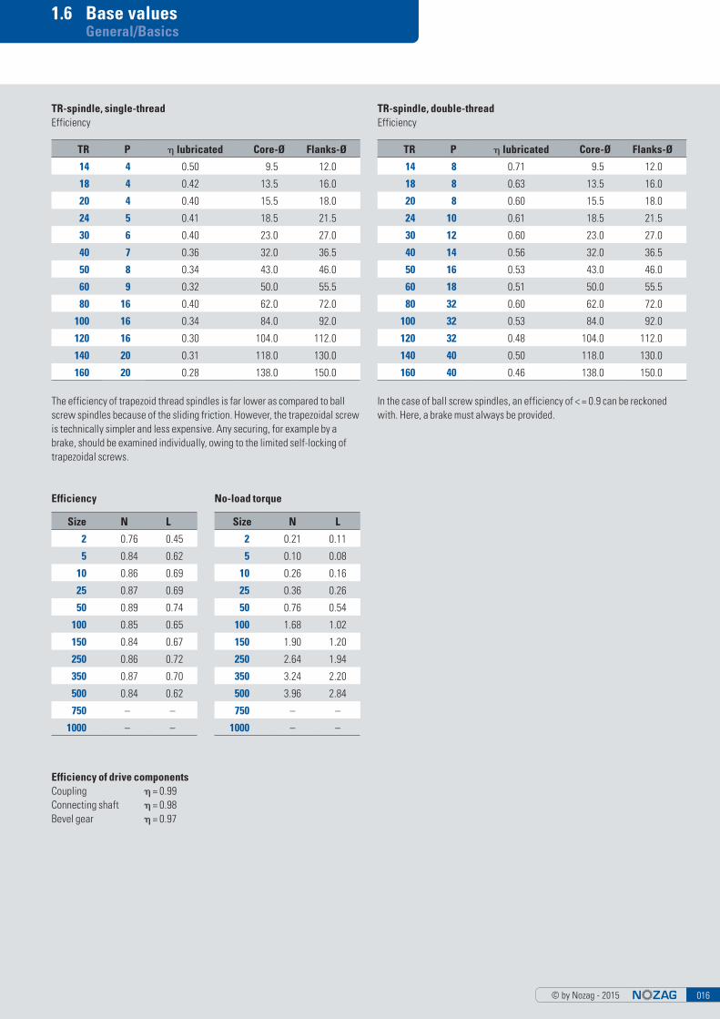
TR-spindle, single-threadEfficiency
Efficiency
TR-spindle, double-threadEfficiency
The efficiency of trapezoid thread spindles is far lower as compared to ball screw spindles because of the sliding friction. However, the trapezoidal screw is technically simpler and less expensive. Any securing, for example by a brake, should be examined individually, owing to the limited self-locking of trapezoidal screws.
No-load torque
In the case of ball screw spindles, an efficiency of < = 0.9 can be reckoned with. Here, a brake must always be provided.
Efficiency of drive componentsCoupling = 0.99Connecting shaft = 0.98Bevel gear = 0.97
Size N L
2 0.76 0.45
5 0.84 0.62
10 0.86 0.69
25 0.87 0.69
50 0.89 0.74
100 0.85 0.65
150 0.84 0.67
250 0.86 0.72
350 0.87 0.70
500 0.84 0.62
750 – –
1000 – –
Size N L
2 0.21 0.11
5 0.10 0.08
10 0.26 0.16
25 0.36 0.26
50 0.76 0.54
100 1.68 1.02
150 1.90 1.20
250 2.64 1.94
350 3.24 2.20
500 3.96 2.84
750 – –
1000 – –

© by Nozag - 2015017
1.7 Design/Calculation General/Basics
Critical buckling force of the lifting spindle
Explanation
I = moment of area of the 2nd degree in mm4
F = max. 1 load/gearbox in NL = free spindle length in mmE = modulus of elasticity for steel (210000 N/mm2)s = safetyfactor (normally 3)d = minimum core diameter of the spindle
Base de conception
F = 19000 N/gearboxL = 836 mms = 3
Formula
l = then d =
Example
l = = = 76882.7 mm4
d = = 35.3 mm minimum core diameter = NSE100 (core-Ø = 50.0 mm)
F x s x (L x 2)2p2 x E
19000 x 3 x (836 mm x 2)2p2 x 210000N/mm2
15.934810 mm4
2072616.9
������������
������������4 l x 64p
19000 x 3 x (836 mm x 2)2p2 x 210000N/mm2
4
Formula
l = then d =
Example
l = = = 19220.7 mm4
d = = 25.0 mm minimum core diameter = NSE50 (core-Ø = 32.0 mm)
������������
F x s x L2
p2 x E
19000 x 3 x 836 mm2
p2 x 210000N/mm23.9837110 mm4
2072616.9
������������4 l x 64p
19220.7 mm4 x 64p
4
Formula
l = then d =
Example
l = = = 9418.1 mm4
d = = 20.9 mm minimum core diameter = NSE25 (core-Ø = 23.0 mm)
������������
F x s x (L x 0.7)2
p2 x E
19000N x 3 x (836 mm x 0.7)2
p2 x 210000N/mm21.952010 mm4
2072616.9
������������4 l x 64p
9418.1 mm4 x 64p2 x 210000N/mm2
4
Load case 1
Load case 3
Load case 2

© by Nozag - 2015 018
1.7 Design/Calculation General/Basics
In the diagram below (calculated with safety 1) with the corresponding load case (1/2/3), determine the point of intersec-tion of buckling force F and the free spindle length L. The point of intersection must be below the line of demarcation of the selected spindle diameter. If this is not the case, a larger spindle or the next larger gearbox should be selected.
TR14x4TR18x4TR20x4
TR24x5
TR30x6
TR40x7
TR50x8
TR60x9
0
spindel length (mm)
500 1000 1500 2000 2500 30000
1
10
100
criti
cal c
ompr
essi
ve fo
rce
(kN
)
0
0
1
10
100
TR14x4
TR18x4TR20x4
TR24x5
TR30x6
TR40x7
TR50x8
TR60x9
500 1000 1500 2000 2500 3000
spindel length (mm)
criti
cal c
ompr
essi
ve fo
rce
(kN
)
0
1
10
100
TR14x4
TR18x4
TR20x4
TR24x5
TR30x6
TR40x7
TR50x8
0 500 1000 1500 2000 2500 3000
spindel length (mm)
criti
cal c
ompr
essi
ve fo
rce
(kN
)
Load case 2
Load case 3
Load case 1

© by Nozag - 2015019
1.7 Design/Calculation General/Basics
Explanation
CP = Spring constantI = Second moment of area (mm4)LK = Free spindle length (mm)E = Modulus of elasticity (N/mm2)dF = Flank diameter of the spindle (mm)ma1 = Weight of the spindle (kg/m)s = Safetyfactor (normally 3)nK = Crit. rotation speed (min-1)
Base de conception
dF = 27.00 mm (TR 30 x 6)LK = 2000 mms = 3ma1 = 4.5 kg/m
Bending critical speed of trapezoid thread spindle
Load case 1
Load case 3
Formula
l = then m = x ma1 then CP =
nk = 150 x
Example
l = = 26087 mm4 m = x 4.5 kg/m = 9 kg
CP = = 32.9
Case 1 according to Euler: nk1 = 150 x = 287 min-1
p x dF4
64LK
100048 x E x I
48 x 210000 x 26087
Lk3
20003
������������CP
m
p x 27.004 2000mm64 1000
������������32.99
Formula
l = then m = x Weight/m then CP =
nk = 420 x
Example:
l = = 26087 mm4 m = x 4.5 kg/m = 9 kg
CP = = 32.9
Case 3 according to Euler: nk3 = 420 x = 803 min-1
p x dF4
64LK
100048 x E x I
48 x 210000 x 26087
Lk3
20003
������������CP
m
p x 27.004 2000mm64 1000
������������32.99

© by Nozag - 2015 020
1.7 Design/Calculation General/Basics
In the diagram below (calculated with safety 1) with the corresponding load case (1/2/3), determine the point of intersection of the spindle rotation speed and the free spindle length L. The point of intersection must be below the line of demarcation of the selected spindle diameter. If this is not the case, a larger spindle or the next larger gearbox should be selected.
0
100
200
300
400
500
00030052000200510001
TR14x4TR18x4TR20x4TR24x5TR30x6
TR40x7
TR50x8
TR60x9
spindel length (mm)
Spin
del r
evol
utio
n sp
eed
(rpm
)
0
100
200
300
400
500
TR14x4
TR18x4TR20x4
TR24x5
TR30x6
TR40x7
1000 1500 2000 2500 3000
spindel length (mm)
Spin
del r
evol
utio
n sp
eed
(rpm
)
Load case 3
Load case 1

© by Nozag - 2015021
Heat balance
In the case of screw jacks with trapezoidal thread spindles, only a small part of the drive power is converted into lifting force.
There are losses in the worm drive and at the trapezoidal thread, which have to be dissipated in the form of heat.
In the case of screwjacks with a non-rotating spindle, the gearbox power loss and the spindle power loss are generated in the gearbox and emitted out-wards through the gearbox housing. In the case of the rotating spindle, the gearbox power loss originates in the gearbox and is dissipated through the gearbox housing; the spindle power loss originates between the spindle and the nut and must be dissipated via the surface of the nut, the spindle and the support plate.
When bellows are used with rotating spindles, particular attention must be paid to the heat balance. Experience has shown that only about 50% of the generated heat can dissipated with the bellows. Therefore, the possible duty cycle is reduced by 50% as compared to an identical design without bellows.
In the case of gearboxes with non-rotating spindles, the bellows are not a problem, since the heat is mostly emitted from the housing.
Influence of the ambient temperatureIf the ambient temperature is higher than 20°C, the load must be reduced, since the higher heat level cannot be emitted. For every 10 °C higher ambient temperature, the load must be reduced by approx. 15–20 %.
1.7 Design/Calculation General/Basics
Air holes must be made by the customer, depending on the speed.

© by Nozag - 2015 022
1.7 Design/Calculation General/Basics
For selecting a suitable screw jack, please check the information on the fol-lowing technical information pages, since various influences and assumptions can only be estimated according to experienced values. In case of doubt, please contact our engineering department.
Load definitionsF – Lifting load tension and/or compressionFS – Lateral load of the spindlevH – Movement speed of the spindle (or nut in case of the rotating version)FA – Axial loading of the input drive shaftFR – Radial loading of the input drive shaftMR – Input drive shaft torquenR – Input drive rotational speed
Lateral forces on the lifting spindleThe maximum permissible lateral forces can be seen from the table below. Basically, lateral forces should be absorbed by means of guides. The guide bushing in the gearbox has only a secondary guiding function. The maximum lateral forces that actually act must be below the values in the table. Caution: only statically permissible
Maximum lateral force FS [N] (static)
deployed spindle length in mm
100 200 300 400 500 600 700 800 900 1000 1200 1500 2000 2500 3000
NSE2 – – – – – – – – – – – – – – –
NSE5 360 160 100 70 55 45 38 32 28 25 20 18 12 – –
NSE10 600 280 180 130 100 80 70 60 50 47 40 30 20 15 –
NSE25 900 470 300 240 180 150 130 110 100 90 70 60 45 35 30
NSE50 3000 2000 1300 900 700 600 500 420 380 330 280 230 160 130 100
NSE100 5000 4000 3000 2300 1800 1500 1300 1100 950 850 700 600 400 350 250
NSE150 5500 5000 3900 2800 2300 1800 1500 1300 1200 1000 850 750 500 400 350
NSE250 9000 9000 6500 4900 3800 3000 2500 2200 2000 1900 1450 1250 900 760 660
NSE350 15000 13000 12000 10000 8800 7000 6000 5500 4800 4300 3500 3000 2000 1600 1400
NSE500 29000 29000 29000 29000 29000 24000 20000 17000 15000 14000 12000 9000 7000 5600 4900
NSE650 34800 34800 34800 34800 34800 28800 24000 20400 18000 16800 14400 10800 8400 6720 5880
NSE750 46000 46000 39000 36000 32000 30000 25000 29000 25000 23500 20000 17000 12000 10000 8000
MR SN/RN MR SL/RL
1500 min-1 1500 min-1
NSE2 2.50 0.80
NSE5 5.60 2.00
NSE10 10.50 4.20
NSE25 22.50 7.80
NSE50 51.00 18.00
NSE100 60.20 20.20
MR SN/RN MR SL/RL
1500 min-1 1500 min-1
NSE150 67.3 17.3
NSE250 118.4 23.5
NSE350 187.0 40.2
NSE500 204.3 42.8
NSE650 268.3 62.8
NSE750 415.0 83.0
FR (N)
NSE2 18
NSE5 110
NSE10 215
NSE25 300
NSE50 520
NSE100 800
FR (N)
NSE150 810
NSE250 1420
NSE350 2100
NSE500 3780
NSE650 4536
NSE750 –
Max. drive torqueThe values given below must not be exceeded. In case of several gearboxes one after another, the drive shaft torque is higher. In case of more than six gearboxes in series, please contact our engineering department.
– Please note that the starting torque is about 1.5 times the operating torque– Limit values are mechanical– Thermal factors must be taken into account, depending on the duty cycle
Radial loading of the drive shaftWhen using chain drives or belt drives, the radial forces FR given below may not be exceeded.
maximum radial loading of the input drive shaft FR [N]
Maximum Forces/torques
vH
Fs
FR
FAMR nR
F

© by Nozag - 2015023
1.7 Design/Calculation General/Basics
Drive torque of a lifting jack
ExplanationsMGe Drive torque [Nm] for one gearboxF Lifting load (dynamic) [kN]Ge Efficiency of the lift drive (without spindle)Sp Efficiency of the spindlelPSp Spindle pitch [mm]i Ratio of the lifting jackML no-load torque [Nm]PGe Drive ratingP1 Drive rating, motor, effectiveKu Efficiency of the couplingnKu Number of couplingsn Motor rpm
Base de conceptionNSE25-RN with F = 16 kN
Ge = 0.87Sp = 0.40Ku = 0.99nKu = 1n = 1400 min-1
Drive torque
MGe = + ML (Nm) MGe = + 0.36 = 7.67 Nm
Motor output
PGe = PGe = = 1.12 kW
P1 = P1eff = = 1.13 kW
F (kN) x PSp (mm)
MGe (Nm) x n (min-1)
PGe
7.67 x 1400
1.12
16 x 62 x p x Ge x Sp x i
9550
(Ku) n Ku
9550
(0.99)1
2 x p x 0.87 x 0.40 x 6
In the case of gearboxes with single-start trapezoid thread spindles, a simplified form of calculation can also be used, which is given on the respective catalogue gearbox page (non-rotating version Chapter 2/rotating version Chapter 3) or in the product data sheets.
We recommend that you multiply the calculated value by a safetyfactor of 1.3 to 1.5 (in the case of small systems, up to 2).
1.13 x 1.5 = 1.7 > Motor with 2.2 kW
Base de conception
Efficiency No-load torque
Base values for calculation (Summary from page 16)
TR Spindle pitch (P)
TR P
14 4
18 4
20 4
30 6
40 7
60 9
Size N L
2 0.76 0.45
5 0.84 0.62
10 0.86 0.69
25 0.87 0.69
50 0.89 0.74
100 0.85 0.65
Size N L
2 0.21 0.11
5 0.10 0.08
10 0.26 0.16
25 0.36 0.26
50 0.76 0.54
100 1.68 1.02

© by Nozag - 2015 024
1.7 Design/Calculation General/Basics
Drive torque of a lifting system
Explanations MGe Drive torque [Nm] for one gearboxF Lifting load (dynamic) [kN]Ge Efficiency of the lift drive (without spindle)Sp Efficiency of the spindlelPSp Spindle pitch [mm]i Ratio of the lifting jackML no-load torque [Nm]PGe Drive ratingP1 Drive rating, motor, effectiveKu Efficiency of the couplingnKu Number of couplingsKe Efficiency of the bevel gearboxnKe Number of bevel gearboxesV Efficiency of the connecting shaftnV Number of connecting shaftsnNSE Number of screw jacks
Base de conceptionNSE25-RN with F = 14 kN
Ge = 0.87Sp = 0.40Ku = 0.99nKu = 4Ke = 0.97nKe = 3V = 0.98nV = 2nNSE = 4n = 1400 min-1
Drive torque
MGe = + ML (Nm) MGe = + 0.36 = 6.76 Nm
Motor output
PGe = nNSE x PGe = 4 x = 3.96 kW
P1 = P1 = = 4.70 kW
We recommend that you multiply the calculated value by a safetyfactor of 1.3 to 1.5 (in the case of small systems, up to 2).
4.70 x 1.5 = 7.06 > Motor with 7.5 kW
F (kN) x PSp (mm)
6MGe (Nm) x n (min-1)
P1
6.76 x 1400
3.96
14 x 62 x p x Ge x Sp x i
9550
(Ku) nKu x (Ke) nKe x (V) nv
9550
(0.99)4 x (0.97)3x (0.98)2
2 x p x 0.87 x 0.40 x 6
Base de conception
Efficiency No-load torque
Base values for calculation (Summary from page 16)
TR Spindle pitch (P)
TR P
14 4
18 4
20 4
30 6
40 7
60 9
Size N L
2 0.76 0.45
5 0.84 0.62
10 0.86 0.69
25 0.87 0.69
50 0.89 0.74
100 0.85 0.65
Size N L
2 0.21 0.11
5 0.10 0.08
10 0.26 0.16
25 0.36 0.26
50 0.76 0.54
100 1.68 1.02

© by Nozag - 2015025
2. Screw jacks, non-rotating

© by Nozag - 2015 026
2. Screw jacks, non-rotating
The worm wheel is provided with a female thread and converts the rotational movement into an axial movement of the spin-dle, when the latter is prevented from rotating (through its design or by means of an anti-rotation protection in the protection tube).
The innovative Nozag screw jack kit makes possible, perfect drive solutions from cost-effective standard components. The kit is subject to the highest standards of functionality, quality and design. A lot can be moved with very little ex-pense and the investment, maintenance and operating costs remain within limits.
Screw jacks developed and manufactured by Nozag solve this task in a simple, inexpensive manner.
Table of Contents Page
2.1 Application examples 27
2.2 Checklist 29
2.3 Sizes/System overview 31
2.4 Sizes/Models 33
2.5 Attachments 47
2.6 Length determination 59
2.7 Section drawing 60
Screw Jacks «Gold» – For Extreme Environmental and Operational Conditions
The shiny casing, mounting flange and cover indicate the highest degree of corrosion resistance. In simple terms, the conventional aluminum components as well as the external parts have been replaced by components made of the aluminum bronze material CuAl10Fe5Ni5. All the spindles and shafts as well as the internal elements are manufactured from stainless steel or synthetic material (seals). ■ High corrosion stability combined with a high degree of wearing resistance
and cavitation protection through CuAl10Fe5Ni5■ Resistance against mechanical damages due to an oxide protection film
(basically Al203) that immediately forms on the material surface■ Excellent performance in applications with gases, fluids and solid materials
The CuAl10Fe5Ni5 material■ features high scaling resistance (up to 800°)■ has a lower degree of corrosion resistance to strongly acidic media with
high oxidation potential (such as nitric acid) as well as alkaline materials, because these will dissolve the oxide coating and prevent its formation.
■ has a lower tendency to selective corrosion (dealumination)
Areas of ApplicationScrew jacks of this design may be used for instance in industrial applications in the vicinity of saline water or sulfuric oxide, in slightly oxidizing and weak alkaline areas, in brackish water, in organic acids (acetate) and in reducing as well as slightly oxidizing mineral acids (diluted hydrochloric, hydrofluoric or phosphoric acid), in environments containing sulfuric acid at room tempera-ture or at elevated temperatures.

© by Nozag - 2015027
2.1 Application examples Screw jacks, non-rotating
Tank opening
Synchronous concrete shuttering adjustment
Conveyor belt height adjustment
Scissor lifting tables

© by Nozag - 2015 028
2.1 Application examples Screw jacks, non-rotating
Solar panel
Slider adjustment in silo
Lifting platforms
Precise roller setting

© by Nozag - 2015029
2.2 Checklist Screw jacks, non-rotating
Lifting force in kN kN per gearbox kN entire installation kN under tensile load kN under compressive load kN static load kN dynamic load
Hours per day 8 16 24 % duty cycle (ED) referred to 10 min
Operating conditions Dryness Dust Humidity Swarf
Ambient temperature °C min. °C max.
Quantity pieces prototype first
Desired delivery dates for quote for delivery
Non-rotating version
Arrangement
Working cycle
(S=stroke, L=time)
Stroke mm stroke mm spindle length
Conditions (operational demands) steady (constant) impact loading (swelling) vibrations (alternating)
Lifting speed (in case of a drive with 1500 min-1) Type = 25 mm/s Type = 6.25 mm/s (NSE2-SN = 20 mm/s) (NSE2-SL = 5.00 mm/s)
Installation position vertical horizontal
Force flow
S (mm)
L (s)
(F=force, S=stroke)
F (kN)
S (mm)
Tens
ion
Pres
sure
Company: Date: Address: Tel.: Fax: Contact person: Mail:
Duty cycle, working cycle Strokes per day Strokes per hour
Motor Three-phase Motor Braking motor Manual drive
Mail [email protected] CH +41 (0)44 805 17 18
1 2 3
5 64
7 8 9
10 11Your arrangement

© by Nozag - 2015 030
2.2 Checklist Screw jacks, non-rotating
Non-rotating version
Operation description / comments / assembls drawing
Attachment CAD File STEP/lges/dxf or PDF or
1 Spindle 2 Mounting flange 3 Ball joint head 4 Fork head 5 Swivel bearing head 6 Bellows 7 Spiral spring cover 8 Lubricant dispenser 9 Motor adapter 10 Flexible coupling 11 Motor 12 Brake motor 13 Spring brake 14 Rotary pulse encoder 15 Protection cap 16 Hand wheel 17 Suspension adapter long 18 Suspension adapter short 19 Suspension bolt 20 Protection tube 21 Limit switch inductive 22 Limit switch mechanical 23 Screw out protection 24 Anti rotation lock
2
13
6
7
15
16
17 18 19
2120
22
24
23
14
12
11
3 4 5
1
9
10
8

© by Nozag - 2015031
2.3 Sizes/System overview Screw jacks, non-rotating
21
3
45
6
7
8 9
10
12
13
14
16
17
15
25
27
26
2423
18
19
21
20 22
11
1 Spiral spring cover 2 Bellows 3 Mounting flange 4 Fork head 5 Ball joint head 6 Swivel bearing head 7 Motor/brake motor 8 Flexible coupling 9 Motor adapter 10 Screw jacks, non-rotating 11 Wear control 12 Screw jacks, non-rotating with safety trap nut 13 Screw jacks, non-rotating with ball screw
14 Protection cap 15 Hand wheel 16 Connecting shafts 17 Bevel gearboxes 18 Lubricant dispenser 19 Support tube 20 Limit switch inductive 21 Limit switch mechanical 22 Protection tube 23 Unscrew protection 24 Anti rotation lock 25 Suspension bolt 26 Suspension adapter short 27 Suspension adapter long
© by Nozag - 2015 032
2.3 Sizes/System overview Screw jacks, non-rotating
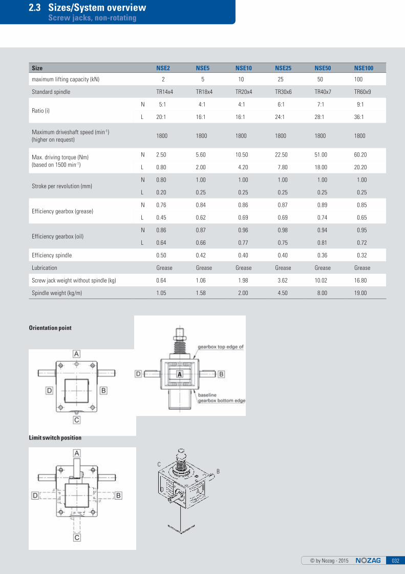
Orientation point
Limit switch position
A
Size NSE2 NSE5 NSE10 NSE25 NSE50 NSE100
maximum lifting capacity (kN) 2 5 10 25 50 100
Standard spindle TR14x4 TR18x4 TR20x4 TR30x6 TR40x7 TR60x9
Ratio (i)N 5:1 4:1 4:1 6:1 7:1 9:1
L 20:1 16:1 16:1 24:1 28:1 36:1
Maximum driveshaft speed (min-1) (higher on request)
1800 1800 1800 1800 1800 1800
Max. driving torque (Nm)(based on 1500 min-1)
N 2.50 5.60 10.50 22.50 51.00 60.20
L 0.80 2.00 4.20 7.80 18.00 20.20
Stroke per revolution (mm)N 0.80 1.00 1.00 1.00 1.00 1.00
L 0.20 0.25 0.25 0.25 0.25 0.25
Efficiency gearbox (grease)N 0.76 0.84 0.86 0.87 0.89 0.85
L 0.45 0.62 0.69 0.69 0.74 0.65
Efficiency gearbox (oil)N 0.86 0.87 0.96 0.98 0.94 0.95
L 0.64 0.66 0.77 0.75 0.81 0.72
Efficiency spindle 0.50 0.42 0.40 0.40 0.36 0.32
Lubrication Grease Grease Grease Grease Grease Grease
Screw jack weight without spindle (kg) 0.64 1.06 1.98 3.62 10.02 16.80
Spindle weight (kg/m) 1.05 1.58 2.00 4.50 8.00 19.00
C
D A
B

© by Nozag - 2015033
2.4 Size 2kN Screw jacks, non-rotating
Maximum lifting capacity: 2 kN (200 kg)Maximum driveshaft speed: 1800 min-1 (higher on request)Spindle: TR 14x4 (standard)
MaterialMaterial (housing): Aluminium, option CuAL10Fe5Ni5Lubrication: Grease, option oil
WeightScrew jack weight: 0.64 kg (with grease/without spindle)Spindle weight: 1.05 kg/m
NSE 2-SN/SL
VersionsSafety trap nut (SFM) see page 43Ball screw (KGT) see page 44
Available on request:■ Double-threaded trapezoidal screw■ Stainlesssteel spindle (INOX)■ Surface-treated spindle
More informationsPlease find CAD - Data and productdatasheets under www.nozag.ch
Attachments > chapter 2.5
Drive components> chapter 4 Motor mounting > chapter 5 Rotating vers. > chapter 3
Features
Ratio Stroke per revolution
Drive- torque1
Max. torque Drive throughtorque2
i mm Nm Nm Nm
NSE2-SN 5:1 0.80 F(kN) x 0.34 + 0.21 2.50 12
NSE2-SL 20:1 0.20 F(kN) x 0.14 + 0.11 0.80 12
1) Factor includes efficiency, ratio and safety 1 2) With more than six gearboxes in series, please contact our technicians
Stro
ke
deep

© by Nozag - 2015 034
2.4 Size 5kN Screw jacks, non-rotating
Attachments > chapter 2.5
Drive components > chapter 4 Motor mounting > chapter 5 Rotating vers. > chapter 3
Maximum lifting capacity: 5 kN (500 kg)Max. Maximum driveshaft speed: 1800 min-1 (higher on request)Spindle: TR 18x4 (standard)
MaterialMaterial (housing): Aluminium, option CuAL10Fe5Ni5Lubrication: Grease, option oil
WeightScrew jack weight: 1.06 kg (with grease/without spindle)Spindle weight: 1.58 kg/m
NSE 5-SN/SL
VersionsSafety trap nut (SFM) see page 43Ball screw (KGT) see page 44
Available on request:■ Double-threaded trapezoidal screw■ Stainlesssteel spindle (INOX)■ Surface-treated spindle
More InformationsPlease find CAD - Data and productdatasheets under www.nozag.ch
Features
Ratio Stroke per revolution
Drive- torque1
Max. torque Drive throughtorque2
i mm Nm Nm Nm
NSE5-SN 4:1 1.00 F(kN) x 0.45 + 0.10 5.60 23
NSE5-SL 16:1 0.25 F(kN) x 0.15 + 0.08 2.00 23
1) Factor includes efficiency, ratio and safety 1 2) With more than six gearboxes in series, please contact our technicians
Stro
ke
deep

© by Nozag - 2015035
2.4 Size 10kN Screw jacks, non-rotating
Maximum lifting capacity: 10 kN (1000 kg)Maximum driveshaft speed: 1800 min-1 (higher on request)Spindle: TR 20x4 (standard)
MaterialMaterial (housing): Aluminium, option CuAL10Fe5Ni5Lubrication: Grease, option oil
WeightScrew jack weight: 1.98 kg (with grease/without spindle)Spindle weight: 2.00 kg/m
NSE 10-SN/SL
VersionsSafety trap nut (SFM) see page 43Ball screw (KGT) see page 44
Available on request:■ Double-threaded trapezoidal screw■ Stainlesssteel spindle (INOX)■ Surface-treated spindle
More informationsPlease find CAD - Data and productdatasheets under www.nozag.ch
Features
Ratio Stroke per revolution
Driving torque1
Max torque Drivethrough torque2
i mm Nm Nm Nm
NSE10-SN 4:1 1.00 F(kN) x 0.46 + 0.26 10.50 42
NSE10-SL 16:1 0.25 F(kN) x 0.14 + 0.16 4.20 42
1) Factor includes efficiency, ratio and safety 1 2) With more than six gearboxes in series, please contact our technicians
Attachments > chapter 2.5
Drive components > chapter 4 Motor mounting > chapter 5 Rotating vers. > chapter 3
deep
Stro
ke

© by Nozag - 2015 036
2.4 Size 25kN Screw jacks, non-rotating
Maximum lifting capacity: 25 kN (2500 kg)Maximum driveshaft speed: 1800 min-1 (higher on request)Spindle: TR 30x6 (standard)
MaterialMaterial (housing): Aluminium, option CuAL10Fe5Ni5Lubrication: Grease, option oil
WeightScrew jack weight: 3.62 kg (with grease/without spindle)Spindle weight: 4.50 kg/m
NSE 25-SN/SL
VersionsSafety trap nut (SFM) see page 43Ball screw (KGT) see page 44
Available on request:■ Double-threaded trapezoidal screw■ Stainlesssteel spindle (INOX)■ Surface-treated spindle
More informationsPlease find CAD - Data and productdatasheets under www.nozag.ch
Features
Ratio Stroke per revolution
Driving torque1
Max torque Drivethrough torque2
i mm Nm Nm Nm
NSE25-SN 6:1 1.00 F(kN) x 0.46 + 0.36 22.50 86
NSE25-SL 24:1 0.25 F(kN) x 0.14 + 0.26 7.80 86
1) Factor includes efficiency, ratio and safety 1 2) With more than six gearboxes in series, please contact our technicians
Attachments > chapter 2.5
Drive components > chapter 4 Motor mounting > chapter 5 Rotating vers. > chapter 3
deep
Stro
ke

© by Nozag - 2015037
Maximum lifting capacity: 50 kN (5000 kg)Maximum driveshaft speed: 1800 min-1 (highter on request)Spindle: TR 40x7 (standard)
MaterialMaterial (housing): Aluminium, option CuAL10Fe5Ni5Lubrication: Grease, option oil
WeightScrew jack weight: 10.02 kg (with grease/without spindle)Spindle weight: 8.00 kg/m
VersionsSafety trap nut (SFM) see page 43Ball screw (KGT) see page 44
Available on request:■ Double-threaded trapezoidal screw■ Stainlesssteel spindle (INOX)■ Surface-treated spindle
More informationsPlease find CAD - Data and productdatasheets under www.nozag.ch
2.4 Size 50kN Screw jacks, non-rotating
NSE 50-SN/SL
Features
Ratio Stroke per revolution
Driving torque1
Max. torque Drive through torque2
i mm Nm Nm Nm
NSE50-SN 7:1 1.00 F(kN) x 0.50 + 0.76 51.00 150
NSE50-SL 28:1 0.25 F(kN) x 0.15 + 0.54 18.00 150
1) Factor includes efficiency, ratio and safety 1 2) With more than six gearboxes in series, please contact our technicians
Attachments > chapter 2.5
Drive components > chapter 4 Motor mounting > chapter 5 Rotating vers. > chapter 3
deep
Stro
ke

© by Nozag - 2015 038
2.4 Size 100kN Screw jacks, non-rotating
Features
Maximum lifting capacity: 100 kN (10000 kg)Maximum driveshaft speed: 1800 min-1 (higher on request)Spindle: TR 60x9 (standard)
MaterialMaterial (housing): Aluminium, option CuAL10Fe5Ni5Lubrication: Grease, option oil
WeightScrew jack weight: 16.80 kg (with grease/without spindle)Spindle weight: 19.00 kg/m
NSE 100-SN/SL
VersionsSafety trap nut (SFM) see page 43Ball screw (KGT) see page 44
Available on request:■ Double-threaded trapezoidal screw■ Stainlesssteel spindle (INOX)■ Surface-treated spindle
More informationsPlease find CAD - Data and productdatasheets under www.nozag.ch
Ratio Stroke per revolution
Driving- torque1
Max. torque Drive through torque2
i mm Nm Nm Nm
NSE100-SN 9:1 1.00 F(kN) x 0.59 + 1.68 60.20 315
NSE100-SL 36:1 0.25 F(kN) x 0.19 + 1.02 20.20 315
1) Factor includes efficiency, ratio and safety 1 2) With more than six gearboxes in series, please contact our technicians
Rotating vers. > chapter 3
Attachments > chapter 2.5
Drive components > chapter 4 Motor mounting > chapter 5
deep
Stro
ke

© by Nozag - 2015039
2.4 Size 150–1000kN Screw jacks, non-rotating
Maximum lifting capacity
NSE150-SN 150kN
NSE150-SL 150kN
NSE250-SN 250kN
NSE250-SL 250kN
NSE350-SN 350kN
NSE350-SL 350kN
NSE500-SN 500kN
NSE500-SL 500kN
NSE750-SN 750kN
NSE750-SL 750kN
NSE1000-SN 1000kN
NSE1000-SL 1000kN
Individual and needs-oriented designScrew jacks from size 150kN usually are used for complex tasks. We develop, manufacture or combine these dimensions individually for your needs. Take advantage of our experience and expertise in simple and complex projects with power requirements over 100kN. We provide very economical solutions, thanks to the modular system, yet also custom-made screw jacks for your needs.
NSE 150–1000-SN/SL
These screw jacks are available in different versions, for example,■ Material (housing): cast Iron / steel■ Double-threaded trapezoidal screws■ Stainless steel screws (INOX)■ Surface-treated screws■ Ball screw s(KGT)■ Safety trap nut (SFM)
Standard SizesThe screw jacks are available with the following lifting forces.
Details and advice on requestWe are happy to help and assist you in details, design and calculation. CAD data or a checklist are available. Please contact us or send us your requirements.

© by Nozag - 2015 040
2.4 Size 150-1000kN Screw jacks, non-rotating

© by Nozag - 2015041
2.4 Long stroke screw jack Screw jacks, non-rotating
Large spindles for long hubs
With longer strokes, usually the spindle diameter is the determining factor for dimensioning and consequently the gearbox will be over dimensioned the NSE25-SN/SL and the NSE50-SN/SL have been specially designed with larger spindles (buckling) – for applicatons with long strokes.
Therefore a compact gearbox can be used, In spite of longer strokes.Other sizes on request.
Maximum lifting capacity: 25 kN (2500 kg)Maximum driveshaft speed: 1800 min-1 (higher on request))Spindle: TR 36x6
MaterialMaterial (housing): AluminiumLubrication: Grease
WeightScrew jack weight: 3.62 kg (with grease / without spindle)Spindle weight: 6.55 kg/m
Available on request■ Double-threaded trapezoidal screw■ Stainlesssteel spindle (INOX)■ Surface-treated spindle
More informationsPlease find CAD - Data and productdatasheets under www.nozag.ch
Features
Ratio Stroke per revolution Driving torque1 Max torque
i mm Nm Nm
NSE25-SN-LH 6:1 1.00 F(kN) x 0.46 + 0.36 22.50
NSE25-SL-LH 24:1 0.25 F(kN) x 0.14 + 0.26 7.80
1) Factor includes efficiency, ratio and safety 1

© by Nozag - 2015 042
2.4 Long stroke screw jack Screw jacks, non-rotating
Maximum lifting capacity: 50 kN (5000 kg)Maximum driveshaft speed: 1800 min-1 (higher on request)Spindle: TR 50x8
MaterialMaterial (housing): AluminiumLubrication: Grease
WeightScrew jack weight: 10.02 kg (with grease/without spindle)Spindle weight: 13.00 kg/m
Available on request■ Double-threaded trapezoidal screw■ Stainlesssteel spindle (INOX)■ Surface-treated spindle
More informationsPlease find CAD - Data and productdatasheets under www.nozag.ch
Features
Ratio Stroke per revolution Driving torque1 Max torque
i mm Nm Nm
NSE50-SN-LH 7:1 1.14 F(kN) x 0.60 + 0.76 51.00
NSE50-SL-LH 28:1 0.29 F(kN) x 0.18 + 0.54 18.00
1) Factor includes efficiency, ratio and safety 1
© by Nozag - 2015043
2.4 Safety trap nut (SFM) Screw jacks, non-rotating
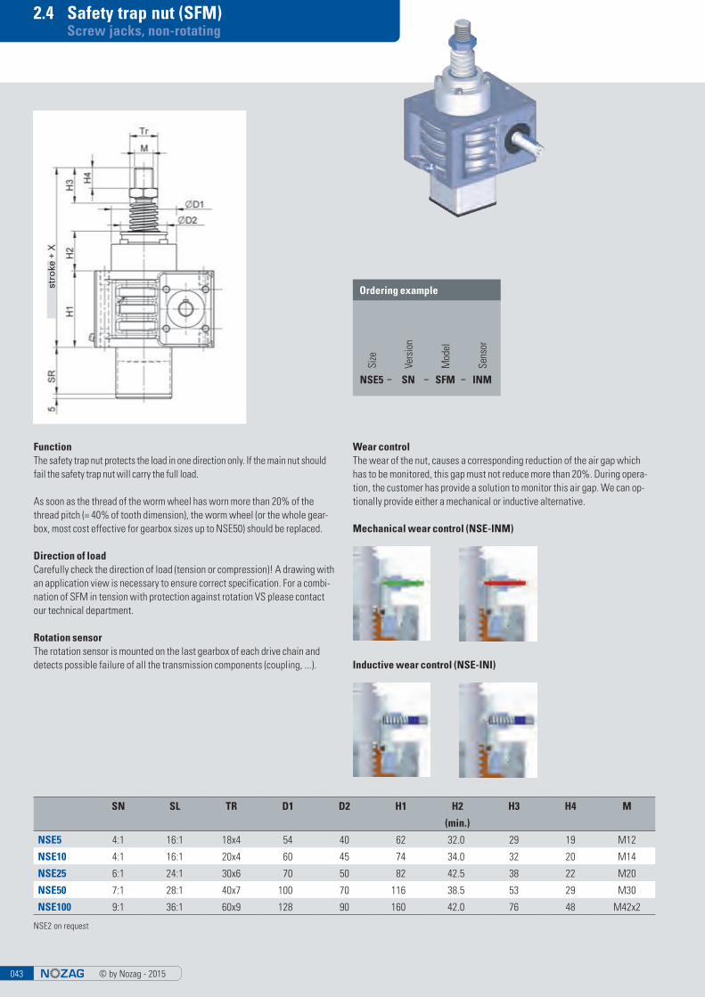
FunctionThe safety trap nut protects the load in one direction only. If the main nut should fail the safety trap nut will carry the full load.
As soon as the thread of the worm wheel has worn more than 20% of the thread pitch (= 40% of tooth dimension), the worm wheel (or the whole gear-box, most cost effective for gearbox sizes up to NSE50) should be replaced.
Direction of loadCarefully check the direction of load (tension or compression)! A drawing with an application view is necessary to ensure correct specification. For a combi-nation of SFM in tension with protection against rotation VS please contact our technical department.
Rotation sensorThe rotation sensor is mounted on the last gearbox of each drive chain and detects possible failure of all the transmission components (coupling, ...).
NSE2 on request
Wear controlThe wear of the nut, causes a corresponding reduction of the air gap which has to be monitored, this gap must not reduce more than 20%. During opera-tion, the customer has provide a solution to monitor this air gap. We can op-tionally provide either a mechanical or inductive alternative.
Mechanical wear control (NSE-INM)
Inductive wear control (NSE-INI)
stro
ke
Ordering example
NSE5
Vers
ion
SN
Sens
or
–Si
ze
Mod
el
SFM– INM–
SN SL TR D1 D2 H1 H2 H3 H4 M
(min.)
NSE5 4:1 16:1 18x4 54 40 62 32.0 29 19 M12
NSE10 4:1 16:1 20x4 60 45 74 34.0 32 20 M14
NSE25 6:1 24:1 30x6 70 50 82 42.5 38 22 M20
NSE50 7:1 28:1 40x7 100 70 116 38.5 53 29 M30
NSE100 9:1 36:1 60x9 128 90 160 42.0 76 48 M42x2

© by Nozag - 2015 044
2.4 Ball screw (KGT) Screw jacks, non-rotating
Accuracy of pitch0.05mm/300mm
Self-lockingNone! Therefore, braking motor or spring-loaded brake FDB necessary
FoulingNuts are always fitted with scrapers. In case of serious fouling and fine dust/chips, we recommend preferably installing bellows or a spiral spring cover.
LubricationAdequate lubrication is an important factor to insure the life of the system, reducing friction and ensuring smooth running. For KGT we use the same lubricants as for ball bearings.
* Stroke per revolution (mm)
ProtectionThe spindle nut must not be removed from the spindle. Screw out protection should be used with the S version.
System starting and brakingEspecially with high pitches and large gearboxes we recommend the use of a frequency inverter for a soft start for acceleration and deceleration. This pro-vides protection for the whole system. Subject to a suitable control system being used the safety distance may be reduced. Please contact the technical department for more information.
Switching-on timeOwing to the lower heat generation with ball screws, you can multiply the swit-ching-on times (ED in % per 10’) by a factor of 2. Please contact us regarding ap-plications with a switching-on time greater than 40 % (4 min per 10 min).
KGT SN* SL* D1 D2 H1 H2 H3 (min.) H4 H5 H6 M Axial play [max.]
Load rating [kN] dynamic static
NSE5 16x05 1.25 0.31 55 40 62 66 10 29 12 19 M12 0.08 9.3 13.1
16x10 2.50 0.63 55 40 62 66 20 29 12 19 M12 0.08 15.4 26.5
NSE10 25x05 1.25 0.31 70 45 74 76 10 32 14 20 M14 0.08 12.3 22.5
25x10 2.50 0.63 70 45 74 76 20 32 14 20 M14 0.08 13.2 25.3
25x25 6.25 1.56 70 45 74 76 50 32 14 20 M14 0.08 16.7 32.2
25x50 12.50 3.13 70 45 74 76 100 32 14 20 M14 0.15 15.4 31.7
NSE25 32x05 0.83 0.21 90 55 82 90 10 38 15 22 M20 0.08 21.5 49.3
32x10 1.67 0.42 90 55 82 90 20 38 15 22 M20 0.08 33.4 54.5
32x20 3.33 0.83 90 55 82 90 40 38 15 22 M20 0.08 29.7 59.8
32x40 6.67 1.67 90 55 82 90 80 38 15 22 M20 0.08 14.9 32.4
NSE50 40x05 0.71 0.18 130 72 116 84 10 53 19 29 M30 0.08 23.8 63.1
40x10 1.43 0.36 130 72 116 84 20 53 19 29 M30 0.08 38.0 69.1
40x20 2.86 0.72 130 72 116 84 40 53 19 29 M30 0.08 33.3 76.1
40x40 5.71 1.43 130 72 116 84 80 53 19 29 M30 0.08 35.0 101.9
NSE100 50x10 1.11 0.28 150 90 160 92 20 76 22 48 M42x2 0.08 68.7 155.8
50x20 2.22 0.56 150 90 160 92 40 76 22 48 M42x2 0.08 60.0 136.3
Ordering example
NSE10
Vers
ion
SL–Si
ze
Mod
el
25x10–
Even more compact designs in development; current status www.nozag.ch

© by Nozag - 2015045
2.4 Actuator Screw jacks, non-rotating
Actuators are designed for tension and compression loads with «eye to eye» function.
Max. storke: buckling calculation (dimension: eye to eye)!When using a hinged bearing plate please consider moments caused by motor weight etc. Support is necessary!
If the main load direction is in tension it is recommended to mount the hinged bearing plate on the spindle side to avoid tension load on the mounting screws.
«A» is the standard position of limit switch and lubrication strip (with anti rotation lock VS). Please specify if another position is required!
Actuator with hinged bearing plate
A B1 B2 B3 B4 C1 C2 C3 D H1 H2 L1 L2 L3 L4 L5NSE2 10 79 15 9 30.5 87 27.5 41.5 5.5 12.5 9 25 50 50 5 25
NSE5 12 98 20 13 36.0 106 31.0 49.0 6.5 15.0 12 25 55 55 5 25
NSE10 12 111 20 13 42.5 126 40.0 60.0 6.5 15.0 12 25 25 55 5 25
NSE25 14 134 30 14 53.0 159 54.5 76.5 8.5 20.0 15 27 27 65 5 25
NSE50 18 177 35 15 73.5 212 79.0 103.0 10.5 30.0 20 33 33 85 10 31
NSE100 20 199 50 17 82.5 234 83.0 117.0 12.5 37.5 30 38 38 100 10 37

© by Nozag - 2015 046
2.4 Actuator STR Screw jacks, non-rotating
Max. storke for actuators STR 500 mmWhen using a support tube for pivot bearing please consider moments caused by motor weight etc. Support is necessary!
It is recommended to use the hinged bearing plate KAL/KAK option where pos-sible: with this version the weight of the gearbox and motor ist directly at the privat point.
«A» is the standard position of limit switch and lubrication strip (with anti rotation lock VS). Please specify if another position is required!
Actuator with support tube for pivot bearing STR
B1 B2 D L1 L2 L3 L4NSE2 20 35 12 100 79 38 5
NSE5 20 35 12 100 88 38 5
NSE10 30 45 20 106 105 38 5
NSE25 30 60 20 113 120 41 5
NSE50 50 80 40 143 166 46 10
NSE100 50 90 40 146 219 49 10
Ordering example
NSE25
Vers
ion
SN–
Size
Mod
el
STR–

© by Nozag - 2015047
2.5 Attachments Screw jacks, non-rotating
TR D L
NSE2-TS TR14x4 M 8 20
NSE5-TS TR18x4 M 12 29
NSE10-TS TR20x4 M 14 32
NSE25-TS TR30x6 M 20 38
NSE50-TS TR40x7 M 30 53
NSE100-TS TR60x9 M 42x2 76
Spindle end, non-rotating
Screw out protection AS Anti rotation lock VS
The screw out protection prevents the screw from being screwed outof the gearbox. Especially recom-mended for ball screws. Do not use the screw out protection as a mechanical stop.
The screw out protection is required when used in combination with limit swichtes.
Anti rotation lock is required to pre-vent the screw from rotating or when used in combination with limit switches or ball joint head KGK.

© by Nozag - 2015 048
2.5 Attachments Screw jacks, non-rotating
Mounting flange BF
Fork head GK
B1 B2 D1 D2 D3 D4 D5
NSE2-BF 20 6 36 5.8 M 8 20 46
NSE5-BF 20 7 48 9.0 M 12 29 65
NSE10-BF 21 8 60 11.0 M 14 38 80
NSE25-BF 23 10 67 11.0 M 20 46 90
NSE50-BF 30 15 85 13.0 M 30 60 110
NSE100-BF 50 20 117 17.0 M 42x2 85 150
B1 B2 D1 D3 L1 L2 L3 L4 M
NSE2-GK 8 16 8 14 16 42 32 12.0 M 8
NSE5-GK 12 24 12 20 24 61 48 18.0 M 12
NSE10-GK 14 28 14 24 28 72 56 22.5 M 14
NSE25-GK 20 40 20 34 40 105 80 30.0 M 20
NSE50-GK 30 60 30 52 60 160 120 42.0 M 30
NSE100-GK 40 85 40 70 84 232 168 63.5 M 42x2

© by Nozag - 2015049
2.5 Attachments Screw jacks, non-rotating
Ball joint head KGK
Swivel bearing head SLK
B D1 D2 L1 L2 L3 M T
NSE5-SLK 18 12 30 48 65 25 M 12 22
NSE10-SLK 24 14 40 56 80 25 M 14 25
NSE25-SLK 30 20 50 80 110 45 M 20 25
NSE50-SLK 35 30 60 92 130 50 M 30 33
NSE100-SLK 57 50 100 155 210 90 M 42x2 70
B1 B2 D1 D2 D3 D4 L1 M SW T
NSE2-KGK 8 6 8 24 16 12.5 36 M 8 14 16
NSE5-KGK 10 8 12 34 22 17.5 50 M 12 19 22
NSE10-KGK 12 10 15 40 26 21.0 61 M 14 22 29
NSE25-KGK 16 13 20 53 35 27.5 77 M 20 32 35
NSE50-KGK 22 19 30 73 43 40.0 110 M 30 41 56
NSE100-KGK 23 28 40 92 65 52.0 142 M 42x2 55 60

© by Nozag - 2015 050
2.5 Attachments Screw jacks, non-rotating
Suspension adapter plate long KAL
Suspension adapter plate short KAK
Suspension adapter bolt KB
B1 B2 D1 D2 H L2 L3 L4
NSE2-KAL 61 43 10 6.5 12.5 51 18.5 67
NSE5-KAL 72 52 15 8.5 15.0 60 21.0 78
NSE10-KAL 85 63 15 8.5 15.0 78 29.0 98
NSE25-KAL 106 81 20 10.5 20.0 106 42.0 128
NSE50-KAL 147 115 30 13.0 30.0 150 63.0 178
NSE100-KAL 165 131 40 17.0 37.5 166 66.0 196
B D1 D2 D3 H L1 L2 L3 L4 L5
NSE2-KB 9 10 20 5.5 10 10 30 15 6 3
NSE5-KB 12 15 25 6.5 12 10 40 20 8 5
NSE10-KB 12 15 25 6.5 12 10 40 20 8 5
NSE25-KB 15 20 30 8.5 14 16 53 30 9 5
NSE50-KB 20 30 40 10.5 18 21 60 35 10 5
NSE100-KB 30 40 50 12.5 20 31 80 50 12 5
B2 B3 D1 D2 H L1 L2
NSE2-KAK 43 59 10 6.5 12.5 69 51
NSE5-KAK 52 70 15 8.5 15.0 80 60
NSE10-KAK 63 83 15 8.5 15.0 100 78
NSE25-KAK 81 103 20 10.5 20.0 131 106
NSE50-KAK 115 143 30 13.0 30.0 182 150
NSE100-KAK 131 161 40 17.0 37.5 200 166
in one piece for
in one piece for

© by Nozag - 2015051
2.5 Attachments Screw jacks, non-rotating
Protection tube SR
Protection cap SK
B S
NSE2-SR 35 2
NSE5-SR 35 2
NSE10-SR 45 2
NSE25-SR 60 3
NSE50-SR 80 3
NSE100-SR 90 4
B1 B2 D1 D2 H1 H2 L1 L2
NSE2-SK 38 28.2 30 5.5 49 28.2 25 6
NSE5-SK 45 32.5 30 7.0 45 32.5 32 8
NSE10-SK 50 35.4 30 9.0 50 35.4 35 8
NSE25-SK 60 42.0 40 9.0 60 42.0 53 8
NSE50-SK 70 50.0 40 11.0 90 70.0 56 8
NSE100-SK 70 46.0 50 13.5 120 96.0 70 8
Protection tube for limit switch SR-ES
B S
NSE2-SR-ES 35 2
NSE5-SR-ES 35 2
NSE10-SR-ES 45 2
NSE25-SR-ES 60 3
NSE50-SR-ES 80 3
NSE100-SR-ES 90 4
© by Nozag - 2015 052
2.5 Attachments Screw jacks, non-rotating
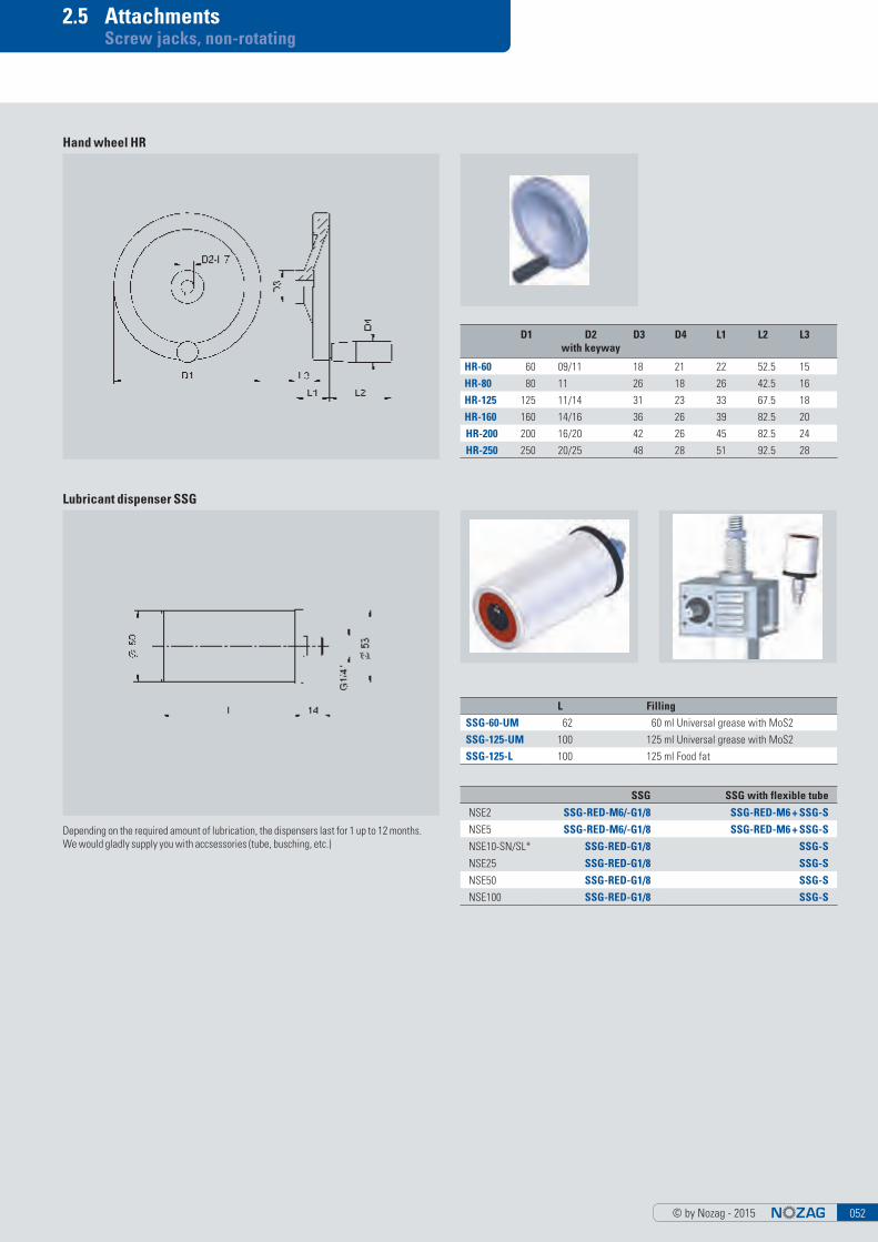
Hand wheel HR
Lubricant dispenser SSG
D1 D2 with keyway
D3 D4 L1 L2 L3
HR-60 60 09/11 18 21 22 52.5 15
HR-80 80 11 26 18 26 42.5 16
HR-125 125 11/14 31 23 33 67.5 18
HR-160 160 14/16 36 26 39 82.5 20
HR-200 200 16/20 42 26 45 82.5 24
HR-250 250 20/25 48 28 51 92.5 28
SSG SSG with flexible tube
NSE2 SSG-RED-M6/-G1/8 SSG-RED-M6 + SSG-S
NSE5 SSG-RED-M6/-G1/8 SSG-RED-M6 + SSG-S
NSE10-SN/SL* SSG-RED-G1/8 SSG-S
NSE25 SSG-RED-G1/8 SSG-S
NSE50 SSG-RED-G1/8 SSG-S
NSE100 SSG-RED-G1/8 SSG-S
Depending on the required amount of lubrication, the dispensers last for 1 up to 12 months.We would gladly supply you with accsessories (tube, busching, etc.)
L Filling
SSG-60-UM 62 60 ml Universal grease with MoS2
SSG-125-UM 100 125 ml Universal grease with MoS2
SSG-125-L 100 125 ml Food fat

© by Nozag - 2015053
2.5 Attachments Screw jacks, non-rotating
Limit switch with 4-pole cable, mounting plate and 2 screws
Limit switch position
Limit switch mechanical ESM
Mechanical limitswitch, shiftable ESMVapproach for limitswitches with bigger movable distance
■ 240V■ IP 65■ Technology: «closer» (NC) and «opener» (NO)■ Opener (NO): Cable color BK (black) and BK-WH (black / white)■ Closer (NC): Cable color BU (blue) and BN (brown)■ IEC / EN 60947-5-1■ Cable length ~ 1 m
3.1(A) 7(P)BK-BK-WHBN-BUBK-BK-WHBN-BU
0 mm
1.4
BN
BU BKWK
BK
Zb
switching element closed switching element opened
TR L1 L2 L3 L4 L5NSE2 TR14x4 25 50 50 5 25
NSE5 TR18x4 25 55 55 5 25
NSE10 TR20x4 25 25 55 5 25
NSE25 TR30x6 27 27 65 5 25
NSE50 TR40x7 33 33 85 10 31
NSE100 TR60x9 38 38 100 10 37
EM EM (mm)
NSE2 6.0
NSE5 6.0
NSE10 6.5
NSE25 7.5
NSE50 8.0
NSE100 8.5

© by Nozag - 2015 054
2.5 Attachments Screw jacks, non-rotating
The inductive proximity switches are mounted on the square end protection tube with a bracket. The desired positions of the proximity switches can be exactly fixed in alignment.
The following standard types are available and can be supplied:■ DC from 10 V to 30 V, max. 200 mA■ PNP■ Switching distance: 2mm■ Output function: «Normally closed» (NC),
option «Normally open» (NO) on request
Limit switch position
Limit switch inductive ESI
Inductive limitswitch, shiftable ESIVapproach for limitswitches with bigger movable distance
143
14
3
143
14
3
TR L1 L2 L3 L4 L5NSE2 TR14x4 25 50 50 5 25
NSE5 TR18x4 25 55 55 5 25
NSE10 TR20x4 25 25 55 5 25
NSE25 TR30x6 27 27 65 5 25
NSE50 TR40x7 33 33 85 10 31
NSE100 TR60x9 38 38 100 10 37
EM EM (mm)
NSE2 2.0
NSE5 2.0
NSE10 2.0
NSE25 3.0
NSE50 3.0
NSE100 4.0

© by Nozag - 2015055
2.5 Bellows Screw jacks, non-rotating
L ZD* AZ* D1 D2 D3 D4
FB52 10 2.1 10.5 26 34 30 52
Screw jack NSE2–NSE5
Material: NBRTemperature range: - 20 … + 80 °C
L ZD* AZ* D1 D2 D3 D4
FB130 20 2.0 26.0 68/88 68/88 70 130
Screw jack NSE100
Material: NBRTemperature range: - 20 … + 80 °C
L ZD* AZ* D1 D2 D3 D4
FB90 20 3.5 24.5 30/40/50 30/40/50 50 90
Screw jack NSE10–NSE50 (NSE5)
Material: Nitril, blackTemperature range: - 20 … + 80 °C
Bellows protect the screw against dirt and moisture.
Particularly in the case of on-site assembly, they protect the spindles from: construction dust, grinding dust from angle grinders, welding spatters, etc. Protect the bellows from direct sunlight. Please note also that the maximum duration of switching on of the lifting jacks is reduced by the heat-insulating action of bellows.
Attention:The bellows must not be compressed below the dimension ZD or extended beyond the dimension AZ. (For strokes greater than 1000 mm, use the bellows with support rings.) Take into consideration that, for horizontal installation of the bellows, it must not come into contact with screw: Serious wear will oc-cure! This can be avoided by the use of support rings.
Ordering example for bellows
Type
Num
ber o
f bel
low
sGa
ite
diam
eter
1/2
FB90-15-30/40
* per foldStandard is FB52-29-26/ 34-300 mit ZD = 60mm
* per fold
* per fold
Air holes must be made by the customer, depending on the speed.

© by Nozag - 2015 056
2.5 Bellows Screw jacks, non-rotating
Depending on accessory, a bellows adapter must be used. Depending on the travel of support rings yet to be built.
Bellow adaptor for spindle end
D
NSE 2-FBAS 30
NSE 5-FBAS 30
NSE 10-FBAS 40
NSE 25-FBAS 40
Bellow adaptor
Support ring
Internal support ring fitting FB90
NSE5-FB90-STR
NSE10-FB90-STR
NSE25-FB90-STR
NSE50-FB90-STR
Internal support ring fitting FB52
NSE2-FB52-STR
NSE5-FB52-STR

© by Nozag - 2015057
Spiral spring covers can be used for different applications. If you want to com-bine different add-on components, centering sleeves are required, which we would be happy to supply.
Important: The spiral spring cover must not be allowed to uncoil. Please specify if the spiral spring cover SF is to be installed vertically or horizontally. We recommend placing the large diameter facing up for vertical installation, and for horizontal installation the large diameter in the direction of the swarf. A light film of oil improves operation and increases the operating life.
2.5 Bellows Screw jacks, non-rotating

© by Nozag - 2015 058
2.5 Spiral spring cover Screw jacks, non-rotating
D1 D2 ZD Stroke horizontal Stroke vertical
045/350/030 45 65 30 260 320
045/550/050 45 68 50 400 500
D1 D2 ZD Stroke horizontal Stroke vertical
050/350/030 50 73 30 260 320
050/550/050 50 73 50 400 500
050/750/060 50 80 60 570 690
050/1100/100 50 77 100 800 1000
D1 D2 ZD Stroke horizontal Stroke vertical
075/350/050 75 95 50 200 300
075/750/060 75 109 60 570 690
075/1100/100 75 108 100 800 1000
075/1500/100 75 120 100 1200 1400
D1 D2 ZD Stroke horizontal Stroke vertical
060/350/050 60 78 50 200 300
060/550/060 60 81 60 370 490
060/750/075 60 89 75 525 675
060/1100/075 60 102 75 875 1025
D1 D2 ZD Stroke horizontal Stroke vertical
100/350/060 100 126 60 170 290
100/800/075 100 138 75 575 725
100/1200/100 100 137 100 900 1100
100/1800/150 100 151 150 1350 1650
Screw jack NSE5
Screw jack NSE10
Screw jack NSE50
Screw jack NSE25
Screw jack NSE100
Ordering example
Smal
lest
dia
met
er D
1
Spira
l spr
ing
Long
est l
engt
h AZ
Smal
lest
leng
th Z
DM
ount
ing
H/V
(h
orizo
ntal
/ver
tical
)
SF-050-0550-050-V

© by Nozag - 2015059
2.6 Length determination Screw jacks, non-rotating
By means of the following table, you can determine the required spindle and pro-tection tube lengths. So that you can quickly calculate the installation dimen-sions of your screw jack. These allowances are the minimum required. For spe-cial installation situations, please make a drawing or contact us.
ExplanationSpindle length = stroke + basic length + attachments
Calculation example
NSE25-SN with 210 mm stroke, anti rotation lock and bellow
Spindle length210 + 164 + 15 + 31.5 = 420.5 mm spindle length
Smallest length bellow210/24.5 = 8.57 9 x 3.5 = 31.5
Protective tube length210 + 25 + 32 = 267
Protective tube length SR
Spindle length
■ Limit switches ESI/ESM are always in combination with anti rotation lock VS or screw out protection AS■ Spiral spring covers SF: As the extension of the spiral spring covering differs depending on the attachment, this
option has to be calculated graphically. If necessary we would be pleased to generate this drawing.
CAD-Datas please look at www.nozag.ch
* Contains 2 x the safety distance (spindle pitch)** Contains 4 x the safety distance (spindle pitch) Subject to dimension changes*** depending on accessory, a bellows adapter must be used
* KGT requires anti-rotation lock VS as being absolutely essential; > included in basic length Subject to dimension changes
NSE2 NSE5 NSE10 NSE25 NSE50 NSE100
TR-basic length* 110 127 145 164 221 298
KGT-basic length** 193 16x05 217 25x05 245 32x05 292 40x05 390 50x10
213 16x10 237 25x10 265 32x10 312 40x10 430 50x20
297 25x25 305 32x20 352 40x20
397 25x50 385 32x40 432 40x40
Basic lengths without protection 102 119 137 152 207 280
Anti rotation lock (VS) /Screw out protection (AS)
15 15 15 15 24 24
bellows adapter*** 8 8 7 6 7 9
Smallest length bellowStroke/10.5 = ........ x 2.1
round number
Stroke/10.5 = ........ x 2.1 round number
Stroke/24.5 = ........ x 3.5 round number
Stroke/24.5 = ........ x 3.5 round number
Stroke/24.5 = ........ x 3.5 round number
Stroke/26.0 = ........ x 2.0 round number
NSE2 NSE5 NSE10 NSE25 NSE50 NSE100
TR-basic length 21 21 21 25 30 37
KGT-basic length* 65 16x05 65 25x05 65 32x05 80 40x05 103 50x05
85 16x10 85 25x10 85 32x10 100 40x10 143 50x10
145 25x25 125 32x20 140 40x20
245 25x50 205 32x40 220 40x40
Anti rotation lock (VS) / Screw out protection (AS)
34 34 34 32 44 48
© by Nozag - 2015 060
2.7 Section drawing Screw jacks, non-rotating
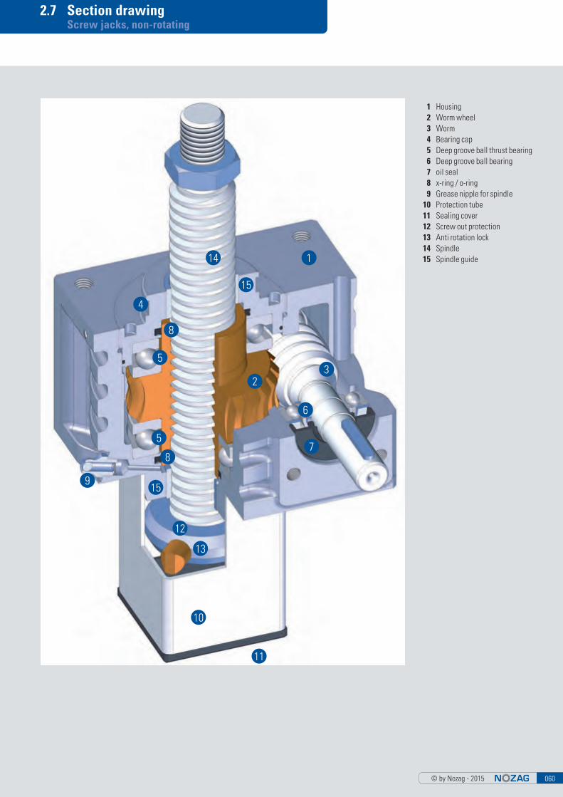
1 Housing 2 Worm wheel 3 Worm 4 Bearing cap 5 Deep groove ball thrust bearing 6 Deep groove ball bearing 7 oil seal 8 x-ring / o-ring 9 Grease nipple for spindle 10 Protection tube 11 Sealing cover 12 Screw out protection 13 Anti rotation lock 14 Spindle 15 Spindle guide114
4
8
5
5
8
9
13
12
10
11
7
6
32
15
15

© by Nozag - 2015061
3. Screw jacks, rotating

© by Nozag - 2015 062
3. Screw jacks, rotating
The spindle has a fixed connection to the worm wheel and rotates with it. The nut therefore screws itself up and down.
The innovative Nozag screw jack kit makes it possible to create perfect drive solutions from cost-effective standard compo-nents. The kit is subject to the highest standards of functionality, quality and design. A lot can be moved with very little ex-pense and the investment, maintenance and operating costs remain within limits.
Screw jacks developed and manufactured by Nozag solve this task in a simple, inexpensive manner.
Table of Contents Page
3.1 Application examples 63
3.2 Checklist 65
3.3 Sizes/system overview 67
3.4 Sizes/models 69
3.5 Attachments 79
3.6 Length determination 87
3.7 Section drawing 88
Screw Jacks «Gold» – For Extreme Environmental and Operational Conditions
The shiny casing, mounting flange and cover indicate the highest degree of corrosion resistance. In simple terms, the conventional aluminum components as well as the external parts have been replaced by components made of the aluminum bronze material CuAl10Fe5Ni5. All the spindles and shafts as well as the internal elements are manufactured from stainless steel or synthetic material (seals). ■ High corrosion stability combined with a high degree of wearing resistance
and cavitation protection through CuAl10Fe5Ni5■ Resistance against mechanical damages due to an oxide protection film
(basically Al203) that immediately forms on the material surface■ Excellent performance in applications with gases, fluids and solid materials
The CuAl10Fe5Ni5 material■ features high scaling resistance (up to 800°)■ has a lower degree of corrosion resistance to strongly acidic media with
high oxidation potential (such as nitric acid) as well as alkaline materials, because these will dissolve the oxide coating and prevent its formation.
■ has a lower tendency to selective corrosion (dealumination)
Areas of ApplicationScrew jacks of this design may be used for instance in industrial applications in the vicinity of saline water or sulfuric oxide, in slightly oxidizing and weak alkaline areas, in brackish water, in organic acids (acetate) and in reducing as well as slightly oxidizing mineral acids (diluted hydrochloric, hydrofluoric or phosphoric acid), in environments containing sulfuric acid at room tempera-ture or at elevated temperatures.

© by Nozag - 2015063
3.1 Application examples Screw jacks, rotating
2
Device adjustment Gripper
Gate openingHeight adjustment of a platform

© by Nozag - 2015 064
3.1 Application examples Screw jacks, rotating
Cover adjustment Lifting movement of a forklift truck
Hub device for silo assembly

© by Nozag - 2015065
3.2 Checklist Screw jacks, rotating
Rotating version
Lifting force in kN kN per gearbox kN entire installation kN under tensile load kN under compressive load kN static load kN dynamic load
Hours per day 8 16 24 % duty cycle (ED) referred to 10 min
Operating conditions Dryness Dust Humidity Swarf
Ambient temperature °C min. °C max.
Quantity pieces prototype first
Desired delivery dates for quote for delivery
Arrangement
Working cycle
(S=stroke, L=time)
Stroke mm stroke mm spindle length
Conditions (operational demands) Steady (constant) Impact loading (swelling) Vibrations (alternating)
Lifting speed (in case of a drive with 1500 min-1) Type RN = 25 mm/s Type RL = 6.25 mm/s (NSE2-RN = 20 mm/s) (NSE2-RL = 5.00 mm/s)
Installation position vertical horizontal
Force flow
S (mm)
L (s)
(F=force, S=stroke)
F (kN)
S (mm)
Tens
ion
Pres
sure
Company: Date: Address: Tel.: Fax: Contact person: Mail:
Duty cycle, working cycle Strokes per day Strokes per hour
Motor Three-phase Motor Braking motor Manual drive
Mail [email protected] CH +41 (0)44 805 17 18
1 2 3
5 64
7 8 9
10 11Your arrangement
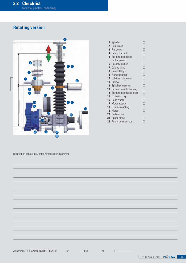
© by Nozag - 2015 066
3.2 Checklist Screw jacks, rotating
Description of function / notes / installation diagramm
Attachment CAD File STEP/LGES/DXF or PDF or
Rotating version
1 Spindle 2 Duplex nut 3 Flange nut 4 Safety trap nut 5 Suspension adapter for flange nut 6 Suspension bolt 7 Calotte disks 8 Carrier flange 9 Flange bearing 10 Lubricant dispenser 11 Bellow 12 Spiral spring cover 13 Suspension adapter long 14 Suspension adapter short 15 Protection cap 16 Hand wheel 17 Motor adapter 18 Flexible coupling 19 Motor 20 Brake motor 21 Spring brake 22 Rotary pulse encoder
9
1
11
11
12
12
10
2
21
19
3
20
4
17
18
22 6 13
15
16
14
6 5
7
8

© by Nozag - 2015067
3.3 Sizes/System overview Screw jacks, rotation
1 Flange bearing 2 Spiral spring cover 3 Bellows 4 Suspension bolt 5 Suspension adapter for flange nut 6 Carrier flange 7 Calotte disks 8 Flange nut/Duplex nut 9 Safety trap nut 10 Motor/brake motor
11 Flexible coupling12 Motor adapter13 Screw jack, rotating 14 Ball screw flange nut 15 Hand wheel 16 Protection cap 17 Connecting shafts18 Suspension adapter long 19 Bevel gearboxes 20 Suspension adapter short
10
11 12
13
1
19
17
3
3
5
4 6
7
9
8
14
204
18
1516
2
2

© by Nozag - 2015 068
3.3 Sizes/System overview Screw jacks, rotating
Orientation point
A
Size NSE2 NSE5 NSE10 NSE25 NSE50 NSE100
maximum lifting capacity (kN) 2 5 10 25 50 100
Standard spindle TR14x4 TR18x4 TR20x4 TR30x6 TR40x7 TR60x9
Ratio (i)N 5:1 4:1 4:1 6:1 7:1 9:1
L 20:1 16:1 16:1 24:1 28:1 36:1
Maximum driveshaft speed (min-1) (higher on request)
1800 1800 1800 1800 1800 1800
Max. driving torque (Nm)(based on 1500 min-1)
N 2.50 5.60 10.50 22.50 51.00 60.20
L 0.80 2.00 4.20 7.80 18.00 20.20
Stroke per revolution (mm)N 0.80 1.00 1.00 1.00 1.00 1.00
L 0.20 0.25 0.25 0.25 0.25 0.25
Efficiency gearbox (grease)N 0.76 0.84 0.86 0.87 0.89 0.85
L 0.45 0.62 0.69 0.69 0.74 0.65
Efficiency gearbox (oil)N 0.86 0.87 0.96 0.98 0.94 0.95
L 0.64 0.66 0.77 0.75 0.81 0.72
Efficiency spindle 0.50 0.42 0.40 0.40 0.36 0.32
Lubrication Grease Grease Grease Grease Grease Grease
Weight screw jack without spindle (kg) 0.64 1.06 1.98 3.62 10.02 16.80
Weight spindle (kg/m) 1.05 1.58 2.00 4.50 8.00 19.00
C
A
B
D

© by Nozag - 2015069
3.4 Size 2kN Screw jacks, rotating
Maximum lifting capacity: 2 kN (200 kg)Maximum driveshaft speed: 1800 min-1 (higher on request)Spindle: TR 14x4 (standard) TR 18x4 (optional, strengthened version)
MaterialMaterial (housing): Aluminium, option CuAL10Fe5Ni5Lubrication: Grease, option oil
WeightScrew jack weight: 0.64 kg (with grease / without spindle)Spindle weight: 1.05 kg/m
NSE 2-RN/RL
VersionsSafety trap nut (SFM) see page 77Ball screw (KGT) see page 78
Available on request:■ Double-threaded trapezoidal screw■ Stainlesssteel spindle (INOX)■ Surface-treated spindle
More informationsPlease find CAD - Data and productdatasheets under www.nozag.ch
Non-rotating version > chapter 2
Features
Ratio Stroke per revolution
Driving torque1
Max. torque Drive through torque2
i mm Nm Nm Nm
NSE2-RN 5:1 0.80 F(kN) x 0.34 + 0.21 2.50 12
NSE2-RL 20:1 0.20 F(kN) x 0.14 + 0.11 0.80 12
NSE2-RN3 5:1 0.80 F(kN) x 0.40 + 0.21 2.50 12
NSE2-RL3 20:1 0.20 F(kN) x 0.17 + 0.11 0.80 12
1) Factor includes efficiency, ratio and safety 1 2) With more than six gearboxes in series, please contact our technicians
3) Optional, strengthened version TR18/4
Attachments > chapter 3.5
Drive components > chapter 4 Motor mounting > chapter 5
Sp
ind
le le
ng
th deep

© by Nozag - 2015 070
3.4 Size 5kN Screw jacks, rotating
Maximum lifting capacity: 5 kN (500 kg)Maximum driveshaft speed: 1800 min-1 (higher on request)Spindle: TR 18x4 (standard) TR 24x5 (optional, strengthened version)
MaterialMaterial (housing): Aluminium, option CuAL10Fe5Ni5Lubrication: Grease, option oil
WeightScrew jack weight: 1.02 kg (with grease / without spindle)Spindle weight: 1.58 kg/m
NSE 5-RN/RL
VersionsSafety trap nut (SFM) see page 77Ball screw (KGT) see page 78
Available on request:■ Double-threaded trapezoidal screw■ Stainlesssteel spindle (INOX)■ Surface-treated spindle
More informationsPlease find CAD - Data and productdatasheets under www.nozag.ch
Non-rotating version > chapter 2
Features
Ratio Stroke per revolution
Driving torque1
Max. torque Drive- through torque2
i mm Nm Nm Nm
NSE5-RN 4:1 1.00 F(kN) x 0.45 + 0.10 5.60 23
NSE5-RL 16:1 0.25 F(kN) x 0.15 + 0.08 2.00 23
NSE5-RN3 4:1 1.25 F(kN) x 0.58 + 0.10 5.60 23
NSE5-RL3 16:1 0.31 F(kN) x 0.20 + 0.08 2.00 23
1) Factor includes efficiency, ratio and safety 1 2) With more than six gearboxes in series, please contact our technicians
3) Optional, strengthened version TR24/5
Attachments > chapter 3.5
Drive components > chapter 4 Motor mounting > chapter 5
Sp
ind
le le
ng
th deep

© by Nozag - 2015071
3.4 Size 10kN Screw jacks, rotating
Maximum lifting capacity: 10 kN (1000 kg)Maximum driveshaft speed: 1800 min-1 (higher on request)Spindle: TR 20x4 (standard) TR 24x5 (optional, strengthened version))
MaterialMaterial (housing): Aluminium, option CuAL10Fe5Ni5Lubrication: Grease, option oil
WeightScrew jack weight: 1.92 kg (with grease / without spindle)Spindle weight: 2.00 kg/m
NSE 10-RN/RL
VersionsSafety trap nut (SFM) see page 77Ball screw (KGT) see page 78
Available on request:■ Double-threaded trapezoidal screw■ Stainlesssteel spindle (INOX)■ Surface-treated spindle
More informationsPlease find CAD - Data and productdatasheets under www.nozag.ch
Non-rotating version > chapter 2
Features
Ratio Stroke per revolution
Driving torque1
Max. torque Drive- through torque2
i mm Nm Nm Nm
NSE10-RN 4:1 1.00 F(kN) x 0.46 + 0.26 10.50 42
NSE10-RL 16:1 0.25 F(kN) x 0.14 + 0.16 4.20 42
NSE10-RN3 4:1 1.25 F(kN) x 0.56 + 0.26 10.50 42
NSE10-RL3 16:1 0.31 F(kN) x 0.18 + 0.16 4.20 42
1) Factor includes efficiency, ratio and safety 1 2) With more than six gearboxes in series, please contact our technicians
3) Optional, strengthened version TR24/5
Attachments > chapter 3.5
Drive components > chapter 4 Motor mounting > chapter 5
Sp
ind
le le
ng
th
deep
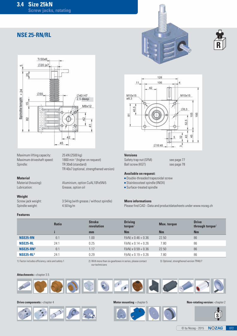
© by Nozag - 2015 072
3.4 Size 25kN Screw jacks, rotating
Maximum lifting capacity: 25 kN (2500 kg)Maximum driveshaft speed: 1800 min-1 (higher on request)Spindle: TR 30x6 (standard) TR 40x7 (optional, strengthened version)
MaterialMaterial (housing): Aluminium, option CuAL10Fe5Ni5Lubrication: Grease, option oil
WeightScrew jack weight: 3.54 kg (with grease / without spindle)Spindle weight: 4.50 kg/m
NSE 25-RN/RL
VersionsSafety trap nut (SFM) see page 77Ball screw (KGT) see page 78
Available on request:■ Double-threaded trapezoidal screw■ Stainlesssteel spindle (INOX)■ Surface-treated spindle
More informationsPlease find CAD - Data and productdatasheets under www.nozag.ch
Non-rotating version > chapter 2
Features
Ratio Stroke revolution
Driving torque1 Max. torque Drive
through torque2
i mm Nm Nm Nm
NSE25-RN 6:1 1.00 F(kN) x 0.46 + 0.36 22.50 86
NSE25-RL 24:1 0.25 F(kN) x 0.14 + 0.26 7.80 86
NSE25-RN3 6:1 1.17 F(kN) x 0.59 + 0.36 22.50 86
NSE25-RL3 24:1 0.29 F(kN) x 0.19 + 0.26 7.80 86
1) Factor includes efficiency, ratio and safety 1 2) With more than six gearboxes in series, please contact our technicians
3) Optional, strengthened version TR40/7
Attachments > chapter 3.5
Drive components > chapter 4 Motor mounting > chapter 5
Sp
ind
le le
ng
th deep

© by Nozag - 2015073
3.4 Size 50kN Screw jacks, rotating
Maximum lifting capacity: 50 kN (5000 kg)Maximum driveshaft speed: 1800 min-1 (higher on request)Spindle: TR 40x7 (standard) TR 50x8 (optional, strengthened version)
MaterialMaterial (housing): Aluminium, option CuAL10Fe5Ni5Lubrication: Grease, option oil
WeightScrew jack weight: 9.98 kg (with grease / without spindle)Spindle weight: 8.00 kg/m
NSE 50-RN/RL
VersionsSafety trap nut (SFM) see page 77Ball screw (KGT) see page 78
Available on request:■ Double-threaded trapezoidal screw■ Stainlesssteel spindle (INOX)■ Surface-treated spindle
More informationsPlease find CAD - Data and productdatasheets under www.nozag.ch
Non-rotating version > chapter 2
Features
Ratio Stroke per revolution
Driving torque1
Max. torque Drive through torque2
i mm Nm Nm Nm
NSE50-RN 7:1 1.00 F(kN) x 0.50 + 0.76 51.00 150
NSE50-RL 28:1 0.25 F(kN) x 0.15 + 0.54 18.00 150
NSE50-RN3 7:1 1.14 F(kN) x 0.60 + 0.76 51.00 150
NSE50-RL3 28:1 0.29 F(kN) x 0.18 + 0.54 18.00 150
1) Factor includes efficiency, ratio and safety 1 2) With more than six gearboxes in series, please contact our technicians
3) Optional, strengthened version TR50/8
Attachments > chapter 3.5
Drive components > chapter 4 Motor mounting > chapter 5
Sp
ind
le le
ng
th deep

© by Nozag - 2015 074
3.4 Size 100kN Screw jacks, rotating
Maximum lifting capacity: 100 kN (10000 kg)Maximum driveshaft speed: 1800 min-1 (higher on request)Spindle: TR 60x9 (standard)
MaterialMaterial (housing): Aluminium, option CuAL10Fe5Ni5Lubrication: Grease, option oil
WeightScrew jack weight: 16.70 kg (with grease / without spindle))Spindle weight: 19.00 kg/m
NSE 100-RN/RL
VersionsSafety trap nut (SFM) see page 77Ball screw (KGT) see page 78
Available on request:■ Double-threaded trapezoidal screw■ Stainlesssteel spindle (INOX)■ Surface-treated spindle
More informationsPlease find CAD - Data and productdatasheets under www.nozag.ch
Non-rotating version > chapter 2
Features
Ratio Stroke per revolution
Driving torque1
Max. torque1 Drive through torque2
i mm Nm Nm Nm
NSE100-RN 9:1 1.00 F(kN) x 0.59 + 1.68 60.20 315
NSE100-RL 36:1 0.25 F(kN) x 0.19 + 1.02 20.20 315
1) Factor includes efficiency, ratio and safety 1 2) With more than six gearboxes in series, please contact our technicians
Ø25 k6
Attachments > chapter 3.5
Drive components > chapter 4 Motor mounting > chapter 5
Sp
ind
le le
ng
th
deep

© by Nozag - 2015075
3.4 Size 150–1000kN Screw jacks, rotating
NSE 150-1000-RN/RL
Maximum lifting capacity
NSE150-RN 150kN
NSE150-RL 150kN
NSE250-RN 250kN
NSE250-RL 250kN
NSE350-RN 350kN
NSE350-RL 350kN
NSE500-RN 500kN
NSE500-RL 500kN
NSE750-RN 750kN
NSE750-RL 750kN
NSE1000-RN 1000kN
NSE1000-RL 1000kN
NSE1000-SL 1000kN
Individual and needs-oriented designScrew jacks from size 150kN usually are used for complex tasks. We develop, manufacture or combine these dimensions individually for your needs. Take advantage of our experience and expertise in simple and complex projects with power requirements over 100kN. We provide very economical solutions, thanks to the modular system, yet also custom-made screw jacks for your needs.
These screw jacks are available in different versions, for example,■ Material (housing): cast Iron / steel■ Double-threaded trapezoidal screws■ Stainless steel screws (INOX)■ Surface-treated screws■ Ball screw s(KGT)■ Safety trap nut (SFM)
Standard SizesThe screw jacks are available with the following lifting forces.
Details and advice on requestWe are happy to help and assist you in details, design and calculation. CAD data or a checklist are available. Please contact us or send us your requirements.

© by Nozag - 2015 076
3.4 Size 150–1000kN Screw jacks, rotating
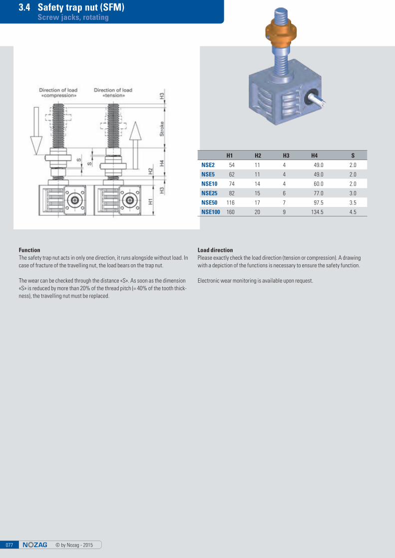
© by Nozag - 2015077
3.4 Safety trap nut (SFM) Screw jacks, rotating
FunctionThe safety trap nut acts in only one direction, it runs alongside without load. In case of fracture of the travelling nut, the load bears on the trap nut.
The wear can be checked through the distance «S». As soon as the dimension «S» is reduced by more than 20% of the thread pitch (= 40% of the tooth thick-ness), the travelling nut must be replaced.
Load directionPlease exactly check the load direction (tension or compression). A drawing with a depiction of the functions is necessary to ensure the safety function.
Electronic wear monitoring is available upon request.
H1 H2 H3 H4 S
NSE2 54 11 4 49.0 2.0
NSE5 62 11 4 49.0 2.0
NSE10 74 14 4 60.0 2.0
NSE25 82 15 6 77.0 3.0
NSE50 116 17 7 97.5 3.5
NSE100 160 20 9 134.5 4.5

© by Nozag - 2015 078
3.4 Ball screw (KGT) Screw jacks, rotating
Pitch accuracy0,05 mm/300 mm
Self-lockingNone! Therefore, braking motor or spring-loaded brake FDB necessary
FoulingNuts are always fitted with scrapers. In case of serious fouling and fine dust/swarf, we recommend installing bellows or a spiral spring cover.
LubricationAdequate lubrication is an important factor to insure the life of the system, reducing friction and ensuring smooth running. For KGT we use the same lubricants as for ball bearings.
LockingThe spindles or nuts must not be unscrewed or disengaged under any circum-stances.
System starting and brakingEspecially with high pitches and large gearboxes we recommend the use of a frequency inverter or a soft start for acceleration and deceleration. This provi-des protection for the whole system. Subject to a suitable control system being used the safety distance may be reduced. Please contact the technical department for more information.
Switching-on timeOwing to the lower heat generation with ball screws, you can multiply the swit-ching-on times (ED in % per 10’) by a factor of 2. Please contact us regarding ap-plications with a switching-on time greater than 40 % (4 min per 10 min).
* Stroke per revolution (mm)
Load rating [kN]
KGT RN* RL* Nut shapeHole
patternB D2 D3 D4 D5 G H1 H2
H3 (min.)
L1 L2 L3 L4Axial play
(max)dy-
namicstatic
NSE5 16x5 1.25 0.31 E 1 40 28 38 48 5.5 M6 62 11 10 42 10 10 – 0.08 9.3 13.1
16x10 2.50 0.63 E 1 40 28 38 48 5.5 M6 62 11 20 55 10 10 – 0.08 15.4 26.5
NSE10 25x5 1.25 0.31 E 1 48 40 51 62 6.6 M6 74 14 10 42 10 10 – 0.08 12.3 22.5
25x10 2.50 0.63 E 1 48 40 51 62 6.6 M6 74 14 20 55 10 16 – 0.08 13.2 25.3
25x25 6.25 1.56 S 1 48 40 51 62 6.6 M6 74 14 50 35 10 9 8 0.08 16.7 32.2
25x50 12.50 3.13 S 1 48 40 51 62 6.6 M6 74 14 100 58 10 10 10 0.08 15.4 31.7
NSE25 32x5 0.83 0.21 E 1 62 50 65 80 9.0 M6 82 15 10 55 12 10 – 0.08 21.5 49.3
32x10 1.67 0.42 E 1 62 53 65 80 9.0 M6 82 15 20 69 12 16 – 0.08 33.4 54.5
32x20 3.33 0.83 E 1 62 53 65 80 9.0 M8x1 82 15 40 80 12 16 – 0.08 29.7 59.8
32x40 6.67 1.67 S 6x60° (round) 53 68 80 7.0 M6 82 15 80 45 16 14 7.5 0.08 14.9 32.4
NSE50 40x5 0.71 0.18 E 2 70 63 78 93 9.0 M6 116 17 10 57 14 10 – 0.08 23.8 63.1
40x10 1.43 0.36 E 2 70 63 78 93 9.0 M8x1 116 17 20 71 14 16 – 0.08 38.0 69.1
40x20 2.86 0.71 E 2 70 63 78 93 9.0 M8x1 116 17 40 80 14 16 – 0.08 33.3 76.1
40x40 5.71 1.43 S 2 (round) 63 78 93 9.0 M8x1 116 17 80 85 14 16 7.5 0.08 35.0 101.9
NSE100 50x10 1.25 0.31 E 2 85 75 93 110 11.0 M8x1 160 20 20 95 16 16 – 0.08 68.7 155.8
50x20 2.50 0.63 E 2 95 85 103 125 11.0 M8x1 160 20 40 95 18 22 – 0.08 60.0 136.3

© by Nozag - 2015079
3.5 Attachments Screw jacks, rotating
Flange nut FM
TR D L
NSE2-TRZ TR14x4 8 15
NSE5-TRZ TR18x4 12 15
NSE10-TRZ TR20x4 15 20
NSE25-TRZ TR30x6 20 25
NSE50-TRZ TR40x7 25 30
NSE100-TRZ TR60x9 40 45
Spindle end, rotating spindle TRZ
TR D1 D2 D3 D4 L1 L2 L3
NSE2-FM TR14x4 38 6 28 48 35 12 8NSE5-FM TR18x4 38 6 28 48 35 12 8NSE10-FM TR20x4 45 7 32 55 44 12 8NSE25-FM TR30x6 50 7 38 62 46 14 8NSE50-FM TR40x7 78 9 63 95 66 16 12
NSE100-FM TR60x9 110 13 88 130 90 20 16
TR
NSE2-TR TR14x4
NSE5-TR TR18x4
NSE10-TR TR20x4
NSE25-TR TR30x6
NSE50-TR TR40x7
NSE100-TR TR60x9
Spindle end, rotating spindle TR

© by Nozag - 2015 080
3.5 Attachments Screw jacks, rotating
Calotte disks KS fitting duplex nut DMN
Safety trap nut SFM
D5 L5 L6
NSE2-R-SFM 25 12 2.0
NSE5-R-SFM 25 12 2.0
NSE10-R-SFM 31 14 2.0
NSE25-R-SFM 40 20 3.0
NSE50-R-SFM 58 28 3.5
NSE100-R-SFM 74 40 4.5
Duplex nut DMN
Remaining dimensions are the same as duplex nut
TR D1 D2 D3 D4 L1 L2 L3 L4
NSE2-DMN TR14x4 38 6 28 48 35 11.5 12 8NSE5-DMN TR18x4 38 6 28 48 35 11.5 12 8NSE10-DMN TR20x4 45 7 32 55 44 16.0 12 8NSE25-DMN TR30x6 58 7 45 70 54 19.0 16 10
NSE50-DMN TR40x7 78 9 63 95 66 25.0 16 12
NSE100-DMN TR60x9 110 13 88 130 90 35.0 20 16
TR D1 D2 D3 D4 L1 L2
NSE2-KS TR14x4 38 6 50 28 27 12
NSE5-KS TR18x4 38 6 50 28 27 12
NSE10-KS TR20x4 45 7 60 32 32 12
NSE25-KS TR30x6 58 7 80 45 36 16
NSE50-KS TR40x7 78 9 100 63 42 16
NSE100-KS TR60x9 110 13 140 88 52 20

© by Nozag - 2015081
3.5 Attachments Screw jacks, rotating
Carrier flange TRMFL for duplex nut or flange nut
Flange bearing FL
NSE-100 TRMFL on request* fits only on duplex nuts DMN
B1 B2 B3 D1 D2 D3 D4 D5 D6
NSE2-FL 7 20 5 48 9 8 29 65 18
NSE5-FL 7 20 5 48 9 12 29 65 20
NSE10-FL 8 21 5 60 11 15 39 80 28
NSE25-FL 10 23 5 67 11 20 46 90 32
NSE50-FL 15 30 5 85 13 25 60 110 42
NSE100-FL 20 50 4 117 17 40 85 150 60
B1 B2 D1 D2 H L1 L2 M1 M2
NSE2-TRMFL 50 34 38 28 35.0 40 24 M5x10 M8x25
NSE5-TRMFL 50 34 38 28 35.0 40 24 M5x10 M8x25
NSE10-TRMFL 58 39 45 32 37.5 40 24 M6x12 M8x25
NSE25-TRMFL* 70 49 58 45 42.5 40 24 M6x12 M10x25
NSE50-TRMFL 100 76 78 63 70.0 65 41 M8x16 M14x43

© by Nozag - 2015 082
3.5 Attachments Screw jacks, rotating
NSE2-KAM on request
Cardan adapter KAM for duplex or flange nut
TR D1 D2 D3 L1 L2 L3
NSE2-KM TR14x4 44 44 10 40 35 8
NSE5-KM TR18x4 50 50 15 46 40 8
NSE10-KM TR20x4 54 54 15 50 44 10
NSE25-KM TR30x6 74 74 20 70 54 10
NSE50-KM TR40x7 100 72 30 94 66 10
NSE100-KM TR60x9 140 90 40 134 90 10
B D1 D2 D3 D5 L1 M
NSE5-KAM 50 38 58 28 15 30 M5x10
NSE10-KAM 57 45 60 32 15 30 M6x12
NSE25-KAM* 78 58 80 45 20 40 M6x12
NSE50-KAM 105 78 110 63 30 60 M8x14
NSE100-KAM 150 110 155 88 40 75 M12x20
* fits only on duplex nuts DMN
Cardan Nut KM
on request

© by Nozag - 2015083
3.5 Attachments Screw jacks, rotating
Suspension adapter plate long KAL
Suspension adapter plate short KAK
Suspension adapter bolt KB
B2 B3 D1 D2 H L1 L2
NSE2-KAK 43 59 10 6.5 12.5 69 51
NSE5-KAK 52 70 15 8.5 15.0 80 60
NSE10-KAK 63 83 15 8.5 15.0 100 78
NSE25-KAK 81 103 20 10.5 20.0 131 106
NSE50-KAK 115 143 30 13.0 30.0 182 150
NSE100-KAK 131 161 40 17.0 37.5 200 166
B D1 D2 D3 H L1 L2 L3 L4 L5
NSE2-KB 9 10 20 5.5 10 10 30 15 6 3
NSE5-KB 12 15 25 6.5 12 10 40 20 8 5
NSE10-KB 12 15 25 6.5 12 10 40 20 8 5
NSE25-KB 15 20 30 8.5 14 16 53 30 9 5
NSE50-KB 20 30 40 10.5 18 21 60 35 10 5
NSE100-KB 30 40 50 12.5 20 31 80 50 12 5
B1 B2 D1 D2 H L2 L3 L4
NSE2-KAL 61 43 10 6.5 12.5 51 18.5 67
NSE5-KAL 72 52 15 8.5 15.0 60 21.0 78
NSE10-KAL 85 63 15 8.5 15.0 78 29.0 98
NSE25-KAL 106 81 20 10.5 20.0 106 42.0 128
NSE50-KAL 147 115 30 13.0 30.0 150 63.0 178
NSE100-KAL 165 131 40 17.0 37.5 166 66.0 196
in one piece for
in one piece for

© by Nozag - 2015 084
3.5 Attachments Screw jacks, rotating
Protection cap SK
Hand wheel HR
D1 D3 D4 L1 L2 L3 D2 with keyway
HR-60 60 18 21 22 52.5 15 09/11
HR-80 80 26 18 26 42.5 16 11
HR-125 125 31 23 33 67.5 18 11/14
HR-160 160 36 26 39 82.5 20 14/16
HR-200 200 42 26 45 82.5 24 16/20
HR-250 250 48 28 51 92.5 28 20/25
B1 B2 D1 D2 H1 H2 L1 L2
NSE2-SK 38 28.2 30 5.5 49 28.2 25 6
NSE5-SK 45 32.5 30 7.0 45 32.5 32 8
NSE10-SK 50 35.4 30 9.0 50 35.4 35 8
NSE25-SK 60 42.0 40 9.0 60 42.0 53 8
NSE50-SK 70 50.0 40 11.0 90 70.0 56 8
NSE100-SK 70 46.0 50 13.5 120 96.0 70 8
Lubricant dispenser SSG
L Filling
SSG-60-UM 62 60 ml Universal grease with MoS2
SSG-125-UM 100 125 ml Universal grease with MoS2
SSG-125-L 100 125 ml Food fat
Depending on the required amount of lubrication, the dispensers last for 1 up to 12 months.We would gladly supply you with accsessories (tube, busching, etc.)
SSG SSG mit Schlauch
NSE2 SSG-RED-M6/-G1/8 SSG-RED-M6 + SSG-S
NSE5 SSG-RED-M6/-G1/8 SSG-RED-M6 + SSG-S
NSE10-RN/RL* SSG-RED-M6/-G1/8 SSG-RED-M6 + SSG-S
NSE25 SSG-RED-G1/8 SSG-S
NSE50 SSG-RED-G1/8 SSG-S
NSE100 SSG-RED-G1/8 SSG-S

© by Nozag - 2015085
3.5 Bellow Screw jacks, rotating
The bellows protect the spindle from dirt and moisture.
Particularly in the case of on-site assembly, they protect the spindles from: construction dust, grinding dust from angle grinders, welding spatters, etc. Protect the bellows from direct sunlight. Please note also that the maximum operation time is reduced by the heat-insulating of the gearboxes effect of the bellows.
Attention:The bellows must not be compressed below the dimension ZD or extended beyond the dimension AZ. (For strokes greater than 1000 mm, use the bellows with support rings.) Take into consideration that, for horizontal installation of the bellows, it must not come into contact with screw: Serious wear will oc-cure! This can be avoided by the use of support rings.
Example for ordering
Type
Num
ber o
f fol
dsGa
iter
diam
eter
1/2
FB90-15-30/40
L ZD* AZ* D1 D2 D3 D4
FB52 10 2.1 10.5 26 34 30 52
Screw jack NSE2–NSE5
Material: NBRTemperature range: - 20 … + 80 °C
L ZD* AZ* D1 D2 D3 D4
FB130 20 2.0 26.0 68/88 68/88 70 130
Screw jack NSE100
Material: NBRTemperature range: - 20 … + 80 °C
L ZD* AZ* D1 D2 D3 D4
FB90 20 3.5 24.5 30/40/50 30/40/50 50 90
Screw jack NSE10–NSE50
Material: Nitril, blackTemperature range: - 20 … + 80 °C
* per foldStandard is FB52-29-26/ 34-300 mit ZD = 60mm
* per fold
* per fold
Air holes must be made by the customer, depending on the speed.
Internal support ring fitting FB90
NSE5-FB-STR
NSE10-FB-STR
NSE25-FB-STR
NSE50-FB-STR
Internal support ring fitting FB52
NSE2-FB52-STR
NSE5-FB52-STR
Support ring

© by Nozag - 2015 086
3.5 Spiral spring cover Screw jacks, rotating
Spiral spring covers can be used for different applications. If you want to com-bine different add-on components, centering sleeves are required, which we would be happy to supply.
Important: The spiral spring cover must not be allowed to uncoil. Please specify if the spiral spring cover SF is to be installed vertically or horizontally. We recommend placing the large diameter facing up for vertical installation, and for horizontal installation the large diameter in the direction of the swarf. A light film of oil improves operation and increases the operating life.
Example for ordering
Inte
ral d
iam
eter
D1
Spira
l spr
ing
cove
r
Long
est l
engt
h AZ
Smal
lest
leng
th Z
DIn
stal
latio
n H/
V (h
orizo
ntal
/ver
tical
)
SF-050-0550-050-V
D1 D2 ZD Stroke horizontal Stroke vertical
045/350/030 45 65 30 260 320
045/550/050 45 68 50 400 500
D1 D2 ZD Stroke horizontal Stroke vertical
050/350/030 50 73 30 260 320
050/550/050 50 73 50 400 500
050/750/060 50 80 60 570 690
050/1100/100 50 77 100 800 1000
D1 D2 ZD Stroke horizontal Stroke vertical
075/350/050 75 95 50 200 300
075/750/060 75 109 60 570 690
075/1100/100 75 108 100 800 1000
075/1500/100 75 120 100 1200 1400
D1 D2 ZD Stroke horizontal Stroke vertical
060/350/050 60 78 50 200 300
060/550/060 60 81 60 370 490
060/750/075 60 89 75 525 675
060/1100/075 60 102 75 875 1025
D1 D2 ZD Stroke horizontal Stroke vertical
100/350/060 100 126 60 170 290
100/800/075 100 138 75 575 725
100/1200/100 100 137 100 900 1100
100/1800/150 100 151 150 1350 1650
Screw jack NSE5
Screw jack NSE10
Screw jack NSE50
Screw jack NSE25
Screw jack NSE100

© by Nozag - 2015087
3.6 Length determination Screw jacks, rotating
By means of the following table, you can determine the required spindle lengths. So that you can quickly calculate the installation dimensions of your screw jack. These allowances are the minimum required. For special installation situations, please make a drawing or contact us.
ExplanationSpindle length = stroke + basic length + attachments
Calculation example
NSE25-RL with 270 mm stroke with pin for flange bearing, Duplex nut and bellow
Spindle length270 + 110 + 54 + 42 = 476 mm spindle length
Smallest length bellow270/24.5 = 11.02 > 12 x 3.5 = 42
NSE2 NSE5 NSE10 NSE25 NSE50 NSE100
TR-basic length* 72 63 72 85 117 194
KGT-basic length** 75 16x05 84 25x05 93 32x05 123 40x05 216 50x10
95 16x10 104 25x10 113 32x10 143 40x10 256 50x20
164 25x25 153 32x20 183 40x20
264 25x50 233 32x40 263 40x40
Basic length without safety 64 55 64 73 103 176
Pin length 15 15 20 25 30.0 45.0
Flange nut 35 35 44 46 66.0 90.0
Flange nut with SFM 49 49 60 69 97.5 134.5
Duplex nut 35 35 44 54 66.0 90.0
Duplex nut with SFM 49 49 60 77 97.5 134.5
KGT-nut L1 see page 78 42 16x05 42 25x05 55 32x05 57 95 50x10
55 16x10 55 25x10 69 32x10 71 40x10 95 50x10
35 25x25 80 32x20 80 40x20
58 25x50 45 32x40 85 40x40
Smallest length bellowStroke/10.5 = ........ x 2.1
round number
Stroke/10.5 = ........ x 2.1 round number
Stroke/24.5 = ........ x 3.5 round number
Stroke/24.5 = ........ x 3.5 round number
Stroke/24.5 = ........ x 3.5 round number
Stroke/26.0 = ........ x 2.0 round number
* Contains 2 x the safety distance (spindle pitch)** Contains 4 x the safety distance (spindle pitch) Subject to dimension changes
■ Spiral spring cover SF: As the extension in case of a spiral spring cover is different depending on the attachment, this option has to be determined graphically. We would be happy to generate this drawing for you.
CAD data can be found at www.nozag.ch

© by Nozag - 2015 088
3.7 Section drawing Screw jacks, rotating
1 Housing 2 Worm wheel 3 Worm 4 Bearing cap 5 Deep groove ball thrust bearing 6 Deep groove ball bearing 7 Oil seal 8 X-ring/O-ring 9 Spindle 10 Duplex nut
1
10
9
4
8
5
5
8
2
3
6
7

© by Nozag - 2015089
4. Drive components
© by Nozag - 2015 090
4. Drive components
Force easily redirected and transmitted.To deliver the required torque for the lifting system at the correct place, you will find in this chapter, the corresponding bevel gear boxes with linking elements like shafts, couplings and bearings.
Table of Contents Page
4.1 Connecting shafts 91
4.2 Pedestal bearings 97
4.3 Clamp coupling 99
4.4 Flexible couplings 101
4.5 Bevel gear LMA 103
4.6 Bevel gear RM 105

© by Nozag - 2015091
4.1 Connecting shaft Drive components
Properties■ Radial mounting possible with split hubs■ Extreamly short assembling and disassembling times■ Spans distances of up to 4 m (13.12 ft)■ No intermediate bearing support required■ Low moment of inertia■ Damps vibration■ Plug-in design■ Free from backlash
Material– Clamping hub: up to series 450 high strength
aluminum, from series 800, steel
Elastomer insert– precision molded, wear resistant and thermally stable polymer
Intermediate tube■ precision aluminum tube■ steel and CFK tubes are also available
Design■ Two coupling hubs are concentrically machined with concave driving jaws■ Elastomer inserts are available in type A or B■ The two coupling elements are connected with a precise and concentrically
optimized aluminum tube
Speed■ Please advise the application speed when ordering or inquiring so we can
check the critical bending speeds.
Tolerance■ On the hub/shaft connection 0.01 to 0.05 mm
Connecting shaft VW

© by Nozag - 2015 092
4.1 Connecting shaft Drive components
VW28 VW35 VW50 VW60 VW76 VW90 VW120
Type (Elastomer insert)
A B A B A B A B A B A B A B
Rated torque (Nm) TKN 12.5 16 17 21 60 75 160 200 325 405 530 660 950 1100
Max. torque* (Nm) TKmax 25.0 32 34 42 120 150 320 400 650 810 1060 1350 1900 2150
Overall length (mm) LA 95 up to 4000 130 up to 4000 175 up to 4000 200 up to 4000 245 up to 4000 280 up to 4000 320 up to 4000
Outer diameter hub (mm)
D4 32 42 56 66.5 82 102 136.5
Outer diameter tube (mm)
D5 28 35 50 60 76 90 120
Outer diameter with screwhead (mm)
D3 32 44.5 57 68 85 105 139
Inner diameter range from Ø to Ø H7 (mm)
D1/2 5–16 8–25 14–32 19–36 19–45 24–60 35–80
Mounting screw (ISO 4762/12.9)
M4 M5 M6 M8 M10 M12 M16
Tightening torque of the mounting screw (Nm)
4 8 15 35 70 120 290
Mounting length (mm) L1 15 17 30 35 40 50 60
Moment of inertia per hub half (10–3 kgm2)
J1/J2 0.01 0.02 0.15 0.21 1.02 2.3 17
Inertia of tube per meter (10–3 kgm2)
J3 0.075 0.183 0.66 1.18 2.48 10.6 38
Torsion ridgidity of both couplings (Nm/rad)
CTdynE 270 825 1270 2220 3970 5950 6700 14650 11850 20200 27700 40600 41300 90000
Torsion ridgidity of 1m of tbe (Nm/rad)
CTZWR 321 1530 6632 11810 20230 65340 392800
L = Clear dimension between the shaft ends
* Maximum transferable torque of the clamping hub depends on the bore diameters

© by Nozag - 2015093
4.1 Connecting shaft Drive components
Connecting shaft VW
0
500
1000
1500
2000
2500
3000
500 1000 1500 2000 2500 3000
Rota
tion
spee
d (r.
p.m
)
Shaft length (mm)
VW28VW35VW50VW60VW76VW90
VW120
Maximum transferable torque of the clamping hub depends on the bore diameters (Nm)
Ø 8 Ø 16 Ø 19 Ø 25 Ø 30 Ø 32 Ø 35 Ø 45 Ø 50 Ø 55 Ø 60 Ø 65 Ø 70 Ø 75 Ø 80
VW28 30 40 50 65
VW35 65 120 150 180 200
VW50 180 240 270 300 330
VW60 300 340 450 520 570 630
VW76 630 720 770 900 1120 1180 1350
VW90 1050 1125 1200 1300 1400 1450 1500 1550 1600
Description of elastomer insert
Type Shore hardness Colour Material relative Absorption Temperature range Property
A 98 Sh A red TPU 0.4 – 0.5 -30° C until +100° C good absorption
B 64 Sh D green TPU 0.3 – 0.4 -30° C until +120° C high torsion stiffness
Ordering example
Type
Type
Ela
stom
er
inse
rtBo
re Ø
D1
H7Bo
re Ø
D2
H7
VW60 – LA 972 – A – 19/24
For us to be able to check your information, please specify the type of arrangement and the spindle distance.
RPM-dependent length determination
Inst
alla
tion
leng
th

© by Nozag - 2015 094
4.1 Connecting shaft Drive components

© by Nozag - 2015095
4.1 Connecting shaft Drive components
Connecting shaft LJ
L = Clear dimension between the shaft ends
The connecting shafts LJ are an inexpensive alternative to the drive shafts, but with limited rotational speeds.
On request availible with clamping hub coupling KNK.
Torque (Nm)D1/D2
min./max.D3 D4 L1 L2
LJ050-… 2.9 6.4 – 15 28 15 15.0 44
LJ075-… 10.1 6.4 – 22 45 20 20.5 54
LJ095-… 21.7 11.1 – 28 54 25 25.5 64
LJ100-… 46.7 11.1 – 34 65 35 35.0 89
0
500
1000
1500
2000
2500
3000
500 1000 1500 2000 2500 3000
LJ050LJ075LJ095LJ100
Rota
tion
spee
d (r.
p.m
)
Shaft length (mm)
RPM-dependent length determination

© by Nozag - 2015 096
4.1 Connecting shaft Drive components
Connecting shaft GX
L = Clear dimension between the shaft ends
Elastic drive shafts serve for joining several screw jacks to one another, or screw jack and drive. They dampen noise, torsional vibrations and impacts, and balance out axial, radial and angular displacements. Elastic drive shafts are maintenance-free, the middle part can be radially (laterally) dismantled without axial displacement of the connected assemblies. Except with very long connections, generally, pedestal bearings are not required.
Features■ particularly torsion-proof■ temperature and oil resistant■ for long lengths and high rotational
speeds■ shaft angle max. 1˚
0
500
1000
1500
2000
2500
3000
500 1000 1500 2000 2500 3000
GX1GX2GX4GX8
Rota
tion
spee
d (r.
p.m
)
Shaft length (mm)
RPM-dependent length determination
Torque [Nm] D1/D2 min./max. D3 D4 D5 D6 L1 L2 L3 L min. Tk/Pitch
GX1 10 8 25 58 56 36 30 24 7 24 87 44/2
GX2 30 12 38 88 86 55 40 28 8 24 88 68/2
GX4 60 16 45 100 100 65 45 30 8 26 99 80/3
GX8 120 20 55 125 120 80 60 42 10 32 120 100/3

© by Nozag - 2015097
4.2 Pedestal bearing Drive components
Pedestal bearings for connecting shafts (STL)
If the connecting shafts or the drive shafts, as the case may be, exceed a certain length and/or rotational speed, pedestal bearings should be used.
Symbol diagram
B D1 D2 H1 H2 L
STL075 38 20 13 36.5 15.0 105
STL095 48 25 17 42.9 17.0 121
STL100 54 35 17 49.2 18.0 137
STLG1 48 30 17 47.6 18.0 127
STLG2 54 40 17 54.0 20.0 146
STLG4 60 45 20 57.2 21.0 159
STL15 25 15 H6 9 22.2 3.2 68
STL20* 32 20 H6 9 25.4 3.2 76
STL25* 32 25 H6 11 28.6 4.0 86
STL35* 42 35 H6 11 39.7 4.6 106
* clamping sleeve on demand. (dimensional variation)

© by Nozag - 2015 098
4.2 Pedestal bearing Drive components
D L
WZ15/80 15 80
WZ20/80 20 80
WZ25/100 25 100
WZ35/120 35 120
Shaft extension
Pedestal bearing with connecting shaft and hand-wheel
Pedestal bearing with connecting shaft
Respectively in the options 0K (no key), 1K (key on one side), 2K (key on both sides)

© by Nozag - 2015099
4.3 Clamp coupling Drive components
Friction coupling KNK
* Maximum transferable torque of the clamping hub depends on the bore diameters
Dimensions, performance list
Higher torque through additional keyway possible
Maximum transferable torque of the clamping hub depends on the bore diameters
ordering example
KNK060
Type
Ela
stom
er in
sert
A
Bor
e Ø
D1 H
7
Bor
e Ø
D2 H
7
19 / 24––
Elastomer insert Rated torqueNm / TKN
Max. torque* Nm / TKmax
A B C A B C
KNK010 12.6 16 4 25 32 6
KNK020 17 21 6 34 42 12
KNK060 60 75 20 120 150 35
KNK150 160 200 42 320 400 85
KNK300 325 405 84 650 810 170
KNK450 530 660 95 1060 1350 190
KNK800 950 1100 240 1900 2150 400
Ø6 Ø8 Ø16 Ø19 Ø25 Ø30 Ø32 Ø35 Ø45 Ø50 Ø55 Ø60 Ø65 Ø70 Ø75 Ø80
KNK010 6 12 32
KNK020 30 40 50 65
KNK060 65 120 150 180 200
KNK150 180 240 270 300 330
KNK300 300 340 450 520 570 630
KNK450 630 720 770 900 1120 1180 1350
KNK800 1050 1125 1200 1300 1400 1450 1500 1550 1600
Properties clamp coupling KNK ■ radial mounting possible■ high concentricity■ damps vibrations■ electrical insulating■ easy mounting / ■ free from backlash■ plug-in design
DesignBoth clamping hubs are fully separable due to split hubs and 2 × ISO 4762 screws per hub. The constructional imbalance of the clamping hubs are counterbalanced due to balancing holes on the innerside.
MaterialClamping hub: up to series 450 high strength aluminum, from series 800, steel, Elastomer insert: precision molded, wear resistant, and thermally stable polymer.

© by Nozag - 2015 100
4.3 Clamp coupling Drive components
Dimensions
Type Elastomer insert KNK010 KNK020 KNK060 KNK150 KNK300 KNK450 KNK800
Overall length mm A 53 66 78 90 114 126 162
Insertion length mm AE 20 28 33 37 49 51 65
Outer diameter mm B 33 42 56 66.5 82 102 136.5
Outer diameter with screwhead mm BS 32 44.5 57 68 85 105 139
Mounting length mm C 20 25 30 35 45 50 65
Inner diameter range from Ø to Ø H7 mm D1/2 6 – 16 8 – 25 12 – 32 19 – 36 20 – 45 28 – 60 35 – 80
Inner diameter max.(elastomer) mm DE 14.2 19.2 26.2 29.2 36.2 46.2 60.5
Mounting screw (ISO 4762/12.9) E M4 M5 M6 M8 M10 M12 M16
Tightening torque of the Mounting screw Nm E 4 8 15 35 70 120 290
Distance between centers mm F 10.5 15.5 21 24 29 38 50.5
Distance mm G 7.5 8.5 10 12 15 17.5 23
Hub length mm H 31 39 46 52.5 66 73 93.5
Moment of inertia per Hub 10-3 kgm2 J1/J2 0.005 0.02 0.06 0.1 0.4 1 9.5
Coupling weight kg 0.08 0.15 0.35 0.6 1.1 1.7 10
Friction coupling KNK
Elastomer insert for friction coupling
Type Shore hardness Couleur Matière Relative Absorption Temperature range Property
A 98 Sh A rot TPU 0.4 – 05.5 -30° C – +100° C high damping
B 64 Sh D grün TPU 0.3 – 04.5 -30° C – +120° C high torsion stiffness
C 80 Sh A gelb TPU 0.3 – 0.4 -30° C – +100° C very high damping
Technical specifications
Type Torsion stiffness static Dynamic Torsional stiffness Angle displacement (degree) Axial displacement Radial displacement
ß A R
GS010
A 260 541 1 0.1
B 600 1650 0.8 ±1 0.08
C 90 224 1.2 0.22
GS020
A 1140 2540 1 0.1
B 2500 4440 0.8 ±2 0.08
C 520 876 1.2 0.15
GS060
A 3290 7940 1 0.12
B 9750 11900 0.8 ±2 0.1
C 1400 1350 1.2 0.15
GS150
A 4970 13400 1 0.15
B 10600 29300 0.8 ±2 0.12
C 1130 3590 1.2 0.2
GS300
A 12400 23700 1 0.18
B 18000 40400 0.8 ±2 0.14
C 1280 6090 1.2 0.25
GS450
A 15100 55400 1 0.2
B 27000 81200 0.8 ±2 0.18
C 4120 11600 1.2 0.25
GS800
A 41300 82600 1 0.25
B 66080 180150 0.8 ±2 0.2
C 10320 28600 1.2 0.3
Radial displacementAngle displacaement Axial displacement

© by Nozag - 2015101
4.4 Flexible couplings Drive components
DesignThese elastique and maintenance free claw couplings are suitable for a prob-lemless usage in general mechanical engineering. They are attractive due to their compact design and comparativly high torque transfer. The couplings are made of two sintered flanges and an elastic insert.
Speed min-1 Material weight D min D max
SOX/Snap Urethan Hytrel Bronze da N L b H kg
035 0.4 – – – 10000 16 – 21 7.0 7 steel 0.05 3.2 9
050 2.9 4.5 5.6 5.6 10000 28 – 44 16.0 12 steel 0.14 6.4 15
070 4.8 7.3 12.8 12.8 8000 35 – 51 19.0 13 steel 0.27 6.4 19
075 10.1 15.3 25.4 25.4 6500 45 – 54 20.5 13 steel 0.45 6.4 22
095 21.7 32.9 62.8 62.8 5800 54 – 64 25.4 13 steel 0.81 11.1 28
100 46.7 70.7 127.0 127.0 5000 65 – 89 35.0 19 steel 1.58 11.1 34
110 88.7 134.0 254.0 254.0 4500 84 – 108 43.0 22 steel 3.00 15.9 41
150 139.0 210.0 415.0 415.0 4000 95 – 114 44.5 25 steel 4.10 15.9 47
190 195.0 293.0 529.0 529.0 3500 114 102 133 54.0 25 alu 3.10 0.0 53
Material of the transmission element
SOX / Buna-N Hytrel Bronze Urethan
Item name GS Hy Bz UR
Temperature range -40 – +100° C -50 – +120° C -20 – +340° C -40 – +71° C
Allowable angular displacement 1° 0.5° 0.5° 1°
Allowable lateral displacement 0.40 mm 0.40 mm 0.25 mm 0.40 mm
Allowable axial displacement 035 – 070 0.75 mm 0.75 mm 0.75 mm 0.75 mm
075 – 190 1.50 mm 1.50 mm 1.50 mm 1.50 mm
The torque and maximum displacement are limited by the chosen flexible transmission element.(Without further specification, a SOX star will be delivered)
Torque with
Flexible couplings
ad N
L
H b
Type 190 of aluminiumType 035-150 Made of sintered steel
ad
L
H b

© by Nozag - 2015 102
4.4 Flexible couplings Drive components
Bore undrilled undrilled undrilled undrilled undrilled undrilled undrilled undrilled undrilled
6.3 6.3 6.3 11.1 11.1 15.9 15.9 19
ø – H7 035 050 070 075 095 100 110 150 190
D min. 035-0 050-0 070-0 075-0 095-0 100-0 110-0 150-0 190-0
8 -8*
9 -9
10 -10 -10* -10*
11 -11 -11 -11
12 -12 -12
14 -14 -14 -14 -14*
15 -15 -15 -15 15*
16 -16 -16
19 -19 -19 -19 19*
20 -20 -20
24 -24 -24
25 -25 -25
28 -28 -28 -28
30 -30 -30
32 -32 -32
35 -35
38 -38
40 -40
42 -42
With standard bores
Table of Coupling half off stock with finished bores, keyway and set screw
Order example for a 075 coupling with a 14 mm and 20 mm bore
1 Coupling half 075-141 Coupling half 075-201 SOX Star 075GS
* without keyway
i other bores on demand
Shaft diameter D bigger than 68
810
1012
1217
1722
2230
3038
3844
4450
5058
5865
6575
7585
Width of keyway H9 2.0 3.0 4.0 5.0 6.0 8.0 10.0 12.0 14.0 16.0 18.0 20.0 22.0
Depth of keyway 1.0 1.4 1.8 2.3 2.8 3.3 3.3 3.3 3.8 4.3 4.4 4.9 5.4
Finished bores according to VSM-H7, Keyways according to VSM 15161-H9 / DIN 6885
Coupling half

4.5 Bevel gearboxes LMA Drive components
The light-construction bevel gearboxes LMA are suitable for the most varied applications in general mechanical engineering and jigmaking.
Bevel gearbox LMA■ for general mechanical engineering■ lightweight series■ max. 1000 min-1
■ Lubrication: Semi-fluid grease (lifelong lubrication)
LMA12 LMA24 LMA60 LMA120 LMA240
n P M P M P M P M P M
1000 0.083 0.79 0.204 1.95 0.513 4.90 1.026 9.80 2.084 19.90
800 0.067 0.80 0.164 1.96 0.438 5.23 0.842 10.05 1.795 21.43
600 0.050 0.80 0.124 1.98 0.362 5.76 0.723 11.51 1.422 22.63
400 0.034 0.81 0.084 2.00 0.276 6.59 0.552 13.17 0.964 23.02
200 0.017 0.83 0.043 2.03 0.144 6.89 0.297 14.18 0.496 23.69
100 0.009 0.84 0.022 2.07 0.073 6.98 0.150 14.34 0.255 24.39
80 0.007 0.85 0.017 2.08 0.059 7.01 0.120 14.38 0.206 24.62
60 0.005 0.85 0.013 2.10 0.044 7.05 0.091 14.45 0.157 24.91
40 0.004 0.89 0.009 2.25 0.032 7.57 0.064 15.36 0.112 26.74
20 0.002 1.08 0.007 3.13 0.022 10.51 0.043 20.39 0.075 35.96
10 0.001 1.30 0.005 4.34 0.015 14.60 0.028 27.08 0.047 45.00
Basics:n = drive rpm (min-1)P = drive power (kW)M = driving torque (Nm)
Life: 6000 h impact-free operation
Housing material■ Aluminium
through shaftShaft according to direction of rotation
Ordering example
Size
Type
Ratio
i Co
ntin
uous
shaf
t
LMA 60 – 1 D
© by Nozag - 2015103

4.5 Bevel gearboxes LMA Drive components
i B D1 D2 H1 L1 L2 L3 L4 L5 L6 L7 L8 L9
LMA12–1 1:1 – 6 5.5 16 20 25.0 17.5 20 17 16.0 17 – –
LMA12–1R 1:1 – 6 5.5 16 20 25.0 17.5 20 17 16.0 17 – –
LMA12–1D 1:1 – 6 5.5 16 20 25.0 17.5 20 17 16.0 17 – –
LMA24–1 1:1 2 8 7.0 21 29 37.0 22.0 17 16 23.0 20 – 12
LMA24–1R 1:1 2 8 7.0 21 29 37.0 22.0 17 16 23.0 20 – 12
LMA24–1D 1:1 2 8 7.0 21 29 37.0 22.0 17 16 23.0 20 – 12
LMA60–1 1:1 3 10 8.5 25 35 43.5 27.5 21 19 27.5 23 – 14
LMA60–1R 1:1 3 10 8.5 25 35 43.5 27.5 21 19 27.5 23 – 14
LMA60–1D 1:1 3 10 8.5 25 35 43.5 27.5 21 19 27.5 23 – 14
LMA120–1 1:1 5 15 8.5 30 42 53.0 32.0 29 27 32.5 27 23 22
LMA120–1R 1:1 5 15 8.5 30 42 53.0 32.0 29 27 32.5 27 23 22
LMA120–1D 1:1 5 15 8.5 30 42 53.0 32.0 29 27 32.5 27 23 22
LMA240–1 1:1 5 17 10.5 35 50 64.0 37.5 31 29 40.0 32 28 22
LMA240–1R 1:1 5 17 10.5 35 50 64.0 37.5 31 29 40.0 32 28 22
LMA240–1D 1:1 5 17 10.5 35 50 64.0 37.5 31 29 40.0 32 28 22
© by Nozag - 2015 104
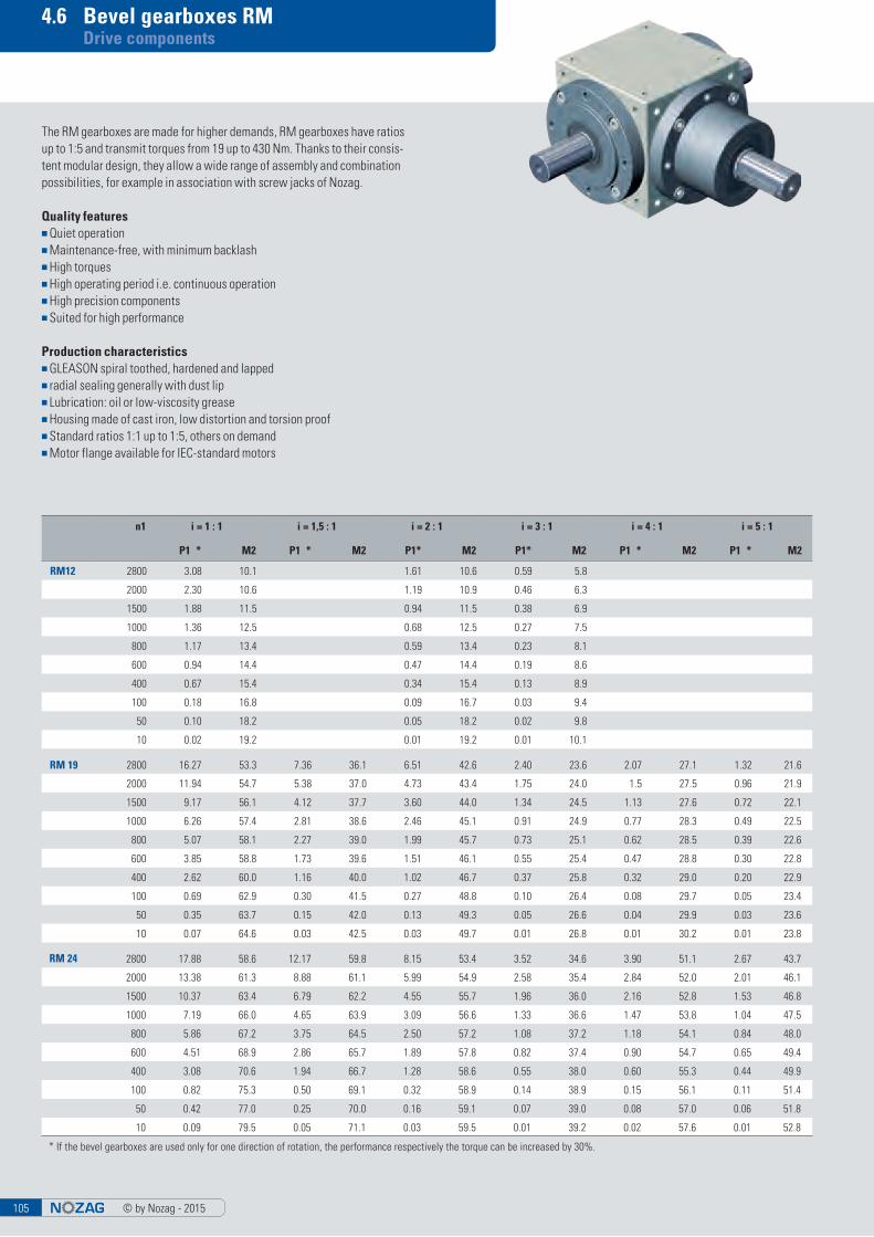
© by Nozag - 20150105
4.6 Bevel gearboxes RM Drive components
n1 i = 1 : 1 i = 1,5 : 1 i = 2 : 1 i = 3 : 1 i = 4 : 1 i = 5 : 1
P1 * M2 P1 * M2 P1* M2 P1* M2 P1 * M2 P1 * M2
RM12 2800 3.08 10.1 1.61 10.6 0.59 5.8
2000 2.30 10.6 1.19 10.9 0.46 6.3
1500 1.88 11.5 0.94 11.5 0.38 6.9
1000 1.36 12.5 0.68 12.5 0.27 7.5
800 1.17 13.4 0.59 13.4 0.23 8.1
600 0.94 14.4 0.47 14.4 0.19 8.6
400 0.67 15.4 0.34 15.4 0.13 8.9
100 0.18 16.8 0.09 16.7 0.03 9.4
50 0.10 18.2 0.05 18.2 0.02 9.8
10 0.02 19.2 0.01 19.2 0.01 10.1
RM 19 2800 16.27 53.3 7.36 36.1 6.51 42.6 2.40 23.6 2.07 27.1 1.32 21.6
2000 11.94 54.7 5.38 37.0 4.73 43.4 1.75 24.0 1.5 27.5 0.96 21.9
1500 9.17 56.1 4.12 37.7 3.60 44.0 1.34 24.5 1.13 27.6 0.72 22.1
1000 6.26 57.4 2.81 38.6 2.46 45.1 0.91 24.9 0.77 28.3 0.49 22.5
800 5.07 58.1 2.27 39.0 1.99 45.7 0.73 25.1 0.62 28.5 0.39 22.6
600 3.85 58.8 1.73 39.6 1.51 46.1 0.55 25.4 0.47 28.8 0.30 22.8
400 2.62 60.0 1.16 40.0 1.02 46.7 0.37 25.8 0.32 29.0 0.20 22.9
100 0.69 62.9 0.30 41.5 0.27 48.8 0.10 26.4 0.08 29.7 0.05 23.4
50 0.35 63.7 0.15 42.0 0.13 49.3 0.05 26.6 0.04 29.9 0.03 23.6
10 0.07 64.6 0.03 42.5 0.03 49.7 0.01 26.8 0.01 30.2 0.01 23.8
RM 24 2800 17.88 58.6 12.17 59.8 8.15 53.4 3.52 34.6 3.90 51.1 2.67 43.7
2000 13.38 61.3 8.88 61.1 5.99 54.9 2.58 35.4 2.84 52.0 2.01 46.1
1500 10.37 63.4 6.79 62.2 4.55 55.7 1.96 36.0 2.16 52.8 1.53 46.8
1000 7.19 66.0 4.65 63.9 3.09 56.6 1.33 36.6 1.47 53.8 1.04 47.5
800 5.86 67.2 3.75 64.5 2.50 57.2 1.08 37.2 1.18 54.1 0.84 48.0
600 4.51 68.9 2.86 65.7 1.89 57.8 0.82 37.4 0.90 54.7 0.65 49.4
400 3.08 70.6 1.94 66.7 1.28 58.6 0.55 38.0 0.60 55.3 0.44 49.9
100 0.82 75.3 0.50 69.1 0.32 58.9 0.14 38.9 0.15 56.1 0.11 51.4
50 0.42 77.0 0.25 70.0 0.16 59.1 0.07 39.0 0.08 57.0 0.06 51.8
10 0.09 79.5 0.05 71.1 0.03 59.5 0.01 39.2 0.02 57.6 0.01 52.8
* If the bevel gearboxes are used only for one direction of rotation, the performance respectively the torque can be increased by 30%.
The RM gearboxes are made for higher demands, RM gearboxes have ratios up to 1:5 and transmit torques from 19 up to 430 Nm. Thanks to their consis-tent modular design, they allow a wide range of assembly and combination possibilities, for example in association with screw jacks of Nozag.
Quality features■ Quiet operation■ Maintenance-free, with minimum backlash■ High torques■ High operating period i.e. continuous operation■ High precision components■ Suited for high performance
Production characteristics■ GLEASON spiral toothed, hardened and lapped■ radial sealing generally with dust lip■ Lubrication: oil or low-viscosity grease■ Housing made of cast iron, low distortion and torsion proof■ Standard ratios 1:1 up to 1:5, others on demand■ Motor flange available for IEC-standard motors
© by Nozag - 2015105

4.6 Bevel gearboxes RM Drive components
n1 i = 1 : 1 i = 1,5 : 1 i = 2 : 1 i = 3 : 1 i = 4 : 1 i = 5 : 1
P1 * M2 P1 * M2 P1* M2 P1* M2 P1 * M2 P1 * M2
RM 32 2800 40.80 133.4 23.50 115.2 15.50 101.8 7.33 72.0 5.42 71.0 3.52 57.6
2000 30.40 139.2 17.60 121.0 11.50 105.6 5.76 79.2 4.14 75.8 2.64 60.5
1500 23.60 144.0 13.70 125.3 8.80 107.5 4.40 80.6 3.14 76.8 2.01 61.4
1000 16.30 149.8 9.40 129.6 6.00 109.4 2.98 82.1 2.12 77.8 1.36 62.4
800 13.30 152.6 7.80 133.9 4.90 111.4 2.43 83.5 1.72 78.7 1.11 63.4
600 10.20 156.5 6.00 136.8 3.70 113.3 1.85 85.5 1.30 79.7 0.85 64.8
400 7.00 160.3 4.10 141.1 2.5 115.2 1.26 86.4 0.88 80.6 0.57 65.8
100 1.90 170.9 1.00 144.0 0.60 119.0 0.32 89.3 0.23 84.5 0.15 67.2
50 0.90 174.7 0.50 146.9 0.30 122.9 0.16 90.7 0.12 96.4 0.07 68.2
10 0.20 180.5 0.10 149.8 0.10 124.8 0.03 92.2 0.02 88.3 0.02 69.1
RM 38 2800 87.2 285.6 57.7 273.5 29.90 196 15.10 148.0 12.30 161.0 9.90 162.0
2000 64.1 294.0 41.0 282.0 22.00 201 11.00 152.0 9.00 164.0 7.20 165.5
1500 49.4 302.0 31.4 288.0 16.90 206 8.40 154.0 6.80 167.0 5.50 168.5
1000 33.8 310.0 21.4 293.8 11.60 212 5.76 158.0 4.60 170.0 3.70 171.0
800 27.6 316.5 17.4 300.0 9.40 215 4.66 160.0 3.70 171.0 3.00 173.0
600 21.1 323.0 13.3 305.0 7.10 218 3.55 162.5 2.80 173.5 2.30 175.0
400 14.5 331.0 9.0 311.0 4.80 222 2.40 165.0 1.90 176.5 1.50 176.5
100 3.8 349.0 2.4 325.5 1.50 231 0.62 170.5 0.50 182.0 0.40 182.0
50 1.9 355.5 1.2 332.5 0.60 234 0.31 172.0 0.25 183.5 0.20 184.0
10 0.4 367.0 0.2 340.0 0.13 239 0.06 175.0 0.05 186.0 0.04 186.0
RM 42 2800 102.6 334.0 62.5 307.0 35.20 230 17.80 175.0 13.70 180.0 9.90 162.0
2000 75.4 346.0 46.0 317.0 25.80 237 13.00 178.0 10.00 183.0 7.20 166.0
1500 58.1 355.0 35.3 324.0 19.80 243 9.90 181.0 7.60 187.0 5.50 178.5
1000 39.8 365.0 24.3 334.0 13.60 249 6.80 186.0 5.20 191.0 3.70 171.0
800 32.5 372.0 19.7 339.0 11.00 253 5.50 188.0 4.20 193.0 3.00 173.0
600 24.9 380.0 15.0 344.0 8.40 257 4.20 191.0 3.20 195.0 2.30 175.0
400 17.0 390.0 10.3 353.0 5.70 261 2.80 194.0 2.20 198.0 1.50 177.0
100 4.5 411.0 2.7 370.0 1.50 272 0.70 201.0 0.60 204.0 0.40 182.0
50 2.3 420.0 1.4 376.0 0.70 278 0.37 203.0 0.25 206.0 0.20 184.0
10 0.5 432.0 0.3 383.0 0.15 281 0.07 206.0 0.05 209.0 0.04 186.0
RM 55 1500 125.0 763.0 88.7 813.0 44.40 543 20.20 370.0 19.50 478.0 15.00 458.0
1000 86.0 787.0 60.7 835.0 30.60 561 13.90 382.0 13.30 489.0 10.20 467.0
800 70.0 800.0 49.4 850.0 23.80 568 11.30 386.0 10.80 495.0 8.20 472.0
600 53.0 810.0 37.7 864.0 18.80 576 8.50 391.0 8.20 501.0 6.30 478.0
400 36.6 840.0 26.0 893.0 12.90 591 5.80 398.0 5.60 509.0 4.20 484.0
100 9.7 896.0 6.9 950.0 3.40 618 41.50 416.0 1.40 529.0 1.10 503.0
50 5.0 912.0 3.5 972.0 1.70 632 0.80 421.0 0.70 534.0 0.60 508.0
10 1.0 941.0 0.7 1000.0 0.35 643 0.16 428.0 0.15 543.0 0.10 515.0
* If the bevel gearboxes are used only for one direction of rotation, the performance respectively the torque can be increased by 30%.
BasicsLife: 20000 hImpact-free operation (F = 1)Operating time 8 h/dayDirection of rotation: clockwise an anticlockwiseAmbient temperature ca. 20 ° C
For different operating characteristics, please consult the correction factor on page 107
Abbreviationsn1 = drive rpm (min-1)n2 = drive rpm (min-1) (smaller rpm)P1 = drive power (kW)M2 = driving torque (Nm)i = ratio (n1/n2)
Note: For continuous operation see page 108
Gearbox range of performance
© by Nozag - 2015 106

© by Nozag - 20150107
4.6 Bevel gearboxes RM design Drive components
hrs/day 24 18 12 8 4 2 1
H 1.25 1.18 1.1 1.0 0.9 0.8 0.7
h 60000 40000 20000 15000 10000 5000 3000
L 1.3 1.15 1 0.95 0.9 0.85 0.8
Load Start ups / hour
non uniform 1 5 20 60 120
uniform 1 1 1.4 1.8 2.2 2.7
light shocks 1 1.4 1.8 2.2 2.7 3.2
large shocks 1 1.4 1.8 2.2 2.7 3.2
Correction factors
for different operating characteristics
Operation time (correction factor H)
Required Life span (correction factor L)
Load factor (correction factor F)
The corrected torque (Mk) can be determined when the appropriate factors are defined.
Mk = M x (H x L x F)
at which:M = theoretically calculated, respectively required torqueMk = corrected torque basis for the choice of gearbox in the table
© by Nozag - 2015107

4.6 Bevel gearboxes RM design Drive components
RM 12 RM 19 RM 24 RM 32 RM 38 RM 42 RM 55
Input power Pt (kW) 1.5 3.0 6.0 10.0 15.0 20.0 35.0
n1 2800 2800 2800 2800 2000 2000 1500
Temperature (°C) – 10 0 10 20 30 40 50
T 1.3 1.25 1.15 1 0.9 0.8 0.7
%-operating period 100 80 60 40 20
ED 1 1.2 1.4 1.6 1.8
Correction factors
Temperature influence (for continuous operation)
In the following table the allowed input power (Pt) is apparent, in which con-tinuous operation (ED 100%) and an ambient temperature of 20°C is not ex-ceeded. A breather is recommended!
For different ambient temperatures and/or operating times, the following correction factors can be used:
Ambient temperature (correction factor T)
Operation time (correction factor ED)
The allowed resulting input power (Pr) can now be calculated as follows:
Pr = Pt x (T x ED)
In case the total actual input power is higher than Pr, the gearbox has to be provided with an external cooling system. In this case, please contact Nozag engineering for advice.
© by Nozag - 2015 108

4.6 Bevel gearboxes RM design Drive components
Table values – Gear choice
Bevel gearboxes mounted in series
In this case, the trough torque is to be observed.
M allowed
RM 19 RM 24 RM 32 RM 38 RM 42 RM 55
M allowed (Nm) 60 120 300 500 700 1600
RM 19 AP RM 24 AP RM 32 AP RM 38 AP RM 42 AP RM 55 AP
M allowed (Nm) 120 300 500 700 1000 3000
RM 12 RM 19 RM 24 RM 32 RM 38 RM 42 RM 55
Weight (kg) 2.5 6 12 22 37 57 87
Note: The allowed torque is only for the shaft and is not applicable to the bevel gearing (Toothing). Also the admissable keyed joint contact pressure (Coupling / Shaft) has to be checked.
For higher torque, bevel gearboxes with larger shaft diameter can be used (Version AP see page 116).
Gearbox weight
© by Nozag - 2015109

4.6 Bevel gearboxes RM design Drive components
Force Ratio RM 12 RM 19 RM 24 RM 32 RM 38 RM 42 RM 55
FR1 (N)1 : 1 2 : 1 3 : 1 550 850 1400 2000 4000 6000 10000
4 : 1 5 : 1 – 600 850 1400 2000 4000 6000
FR2 (N) All ratios 900 1500 2200 3500 7000 10000 15000
Force Ratio RM 12 RM 19 RM 24 RM 32 RM 38 RM 42 RM 55
FA1 (N) 1 : 1 2 : 1 3 : 1 300 450 700 1100 1700 2700 5000
4 : 1 5 : 1 – 400 450 700 1100 1700 2700
FA2 (N) All ratios 500 700 1300 1700 3400 4800 6800
Table values – Gear choice
Permitted shaft loads
== = =
Gearboxes with hollow shaft (Type H) and larger pass through shafts (Version AP see page 116) on demand!
FR1 FR2
FA1 FA2
© by Nozag - 2015 110

4.6 Bevel gearboxes RM Drive components
RM, shaft on one side
Entry sense of rotation contrary to output sense of rotation
Ordering example
Size
Type
Ratio
i = 1
:1
RM 24 – 1
:1 A B C D1 j6 D2 j6 D3 h7 D4 h7 D5 E F G H L1 L2
RM 12 1, 2, 3 116 72 46 12 12 44 65 54 42 2 74 32,5 26 26
RM 19 1, 2, 3, 168 105 65 19 19 60 86 72 59 4 100 45,0 40 40
4, 5 14 30
RM 24 1, 2, 3, 208 130 80 24 24 70 105 88 73 5 115 55,0 50 50
4, 5 19 40
RM 32 1, 2, 3, 248 155 95 32 32 95 135 115 88 5 145 70,0 60 60
4, 5 24 50
RM 38 1, 2, 3, 288 180 110 38 38 120 165 145 103 5 170 85,0 70 70
4, 5 28 60
RM 42 1, 2, 3, 328 205 125 42 42 135 190 165 118 5 195 100 80 80
4, 5 32 60
RM 55 1, 2, 3, 408 260 150 55 55 170 230 205 143 5 245 120 110 110
4, 5 42 80
:1 M N O P R S1 S2 C1 C2 T
RM 12 1, 2, 3 100 65 45 M 6 M 6 M4 x 8 M 4 x 8 20 x 4 x 4 20 x 4 x 4 9,5
RM 19 1, 2, 3, 140 90 70 M 6 M 6 M 6 x 12 M 6 x 12 35 x 6 x 6 35 x 6 x 6 14
4, 5 130 M 5 x 10 25 x 5 x 5 35 x 6 x 6
RM 24 1, 2, 3, 165 110 88 M 8 M 8 M 8 x 16 M 8 x 16 40 x 8 x 7 40 x 8 x 7 18
4, 5 155 M 6 x 12 35 x 6 x 6
RM 32 1, 2, 3, 205 140 110 M 10 M 10 M 10 x 20 M 10 x 20 50 x 10 x 8 50 x 10 x 8 18
4, 5 195 M 8 x 16 40 x 8 x 7
RM 38 1, 2, 3, 240 170 136 M 12 M 12 M 12 x 24 M 12 x 24 60 x 10 x 8 60 x 10 x 8 18
4, 5 230 M 10 x 20 50 x 8 x 7 60 x 10 x 8
RM 42 1, 2, 3, 275 200 155 M 12 M 12 M 12 x 24 M 12 x 24 70 x 12 x 8 70 x 12 x 8 18
4, 5 255 M 10 x 20 50 x 10 x 8
RM 55 1, 2, 3, 355 240 190 M 14 M 14 M 14 x 28 M 14 x 28 100 x 16 x 10 100 x 16 x 10 23
4, 5 325 M 12 x 24 70 x 12 x 8
© by Nozag - 2015111
in RM 12 not available

4.6 Bevel gearboxes RM Drive components
RM, shaft on one side
Entry sense of rotation same as output sense of rotation
:1 A B C D1 j6 D2 j6 D3 h7 D4 h7 D5 E F G H L1 L2
RM 12 1, 2, 3 116 72 46 12 12 44 65 54 42 2 74 32,5 26 26
RM 19 1, 2, 3, 168 105 65 19 19 60 86 72 59 4 100 45,0 40 40
4, 5 14 30
RM 24 1, 2, 3, 208 130 80 24 24 70 105 88 73 5 115 55,0 50 50
4, 5 19 40
RM 32 1, 2, 3, 248 155 95 32 32 95 135 115 88 5 145 70,0 60 60
4, 5 24 50
RM 38 1, 2, 3, 288 180 110 38 38 120 165 145 103 5 170 85,0 70 70
4, 5 28 60
RM 42 1, 2, 3, 328 205 125 42 42 135 190 165 118 5 195 100 80 80
4, 5 32 60
RM 55 1, 2, 3, 408 260 150 55 55 170 230 205 143 5 245 120 110 110
4, 5 42 80
:1 M N O P R S1 S2 C1 C2 T G H L1 L2
RM 12 1, 2, 3 100 65 45 M 6 M 6 M4 x 8 M 4 x 8 20 x 4 x 4 20 x 4 x 4 9,5 74 32,5 26 26
RM 19 1, 2, 3, 140 90 70 M 6 M 6 M 6 x 12 M 6 x 12 35 x 6 x 6 35 x 6 x 6 14 100 45,0 40 40
4, 5 130 M 5 x 10 25 x 5 x 5 35 x 6 x 6 30
RM 24 1, 2, 3, 165 110 88 M 8 M 8 M 8 x 16 M 8 x 16 40 x 8 x 7 40 x 8 x 7 18 115 55,0 50 50
4, 5 155 M 6 x 12 35 x 6 x 6 40
RM 32 1, 2, 3, 205 140 110 M 10 M 10 M 10 x 20 M 10 x 20 50 x 10 x 8 50 x 10 x 8 18 145 70,0 60 60
4, 5 195 M 8 x 16 40 x 8 x 7 50
RM 38 1, 2, 3, 240 170 136 M 12 M 12 M 12 x 24 M 12 x 24 60 x 10 x 8 60 x 10 x 8 18 170 85,0 70 70
4, 5 230 M 10 x 20 50 x 8 x 7 60 x 10 x 8 60
RM 42 1, 2, 3, 275 200 155 M 12 M 12 M 12 x 24 M 12 x 24 70 x 12 x 8 70 x 12 x 8 18 195 100 80 80
4, 5 255 M 10 x 20 50 x 10 x 8 60
RM 55 1, 2, 3, 355 240 190 M 14 M 14 M 14 x 28 M 14 x 28 100 x 16 x 10 100 x 16 x 10 23 245 120 110 110
4, 5 325 M 12 x 24 70 x 12 x 8 80
Ordering example
Size
Type
Ratio
i = 1
:1
RM 19 – 1 R
Dire
ctio
n of
rota
tion
© by Nozag - 2015 112
in RM 12 not available

4.6 Bevel gearboxes RM Drive components
RM, through shaft
Ordering example
Size
Type
Ratio
i = 2
:1
RM 12 – 2 D
thro
ugh
shaf
t
:1 A B C D1 j6 D2 J6 D3 h7 D4 h7 D5 E F G H L1 L2
RM 12 1, 2, 3 144 72 46 12 12 44 65 54 42 2 74 32,5 26 26
RM 19 1, 2, 3, 210 105 65 19 19 60 86 72 59 4 100 45,0 40 40
4, 5 14 30
RM 24 1, 2, 3, 260 130 80 24 24 70 105 88 73 5 115 55,0 50 50
4, 5 19 40
RM 32 1, 2, 3, 310 155 95 32 32 95 135 115 88 5 145 70,0 60 60
4, 5 24 50
RM 38 1, 2, 3, 360 180 110 38 38 120 165 145 103 5 170 85,0 70 70
4, 5 28 60
RM 42 1, 2, 3, 410 205 125 42 42 135 190 165 118 5 195 100 80 80
4, 5 32 60
RM 55 1, 2, 3, 520 260 150 55 55 170 230 205 143 5 245 120 110 110
4, 5 42 80
:1 M N O P R S1 S2 C1 C2 T G H L1 L2
RM 12 1, 2, 3 100 65 45 M 6 M 6 M 4 x 8 M 4 x 8 20 x 4 x 4 20 x 4 x 4 9,5 74 32,5 26 26
RM 19 1, 2, 3, 140 90 70 M 6 M 6 M 6 x 12 M 6 x 12 35 x 6 x 6 35 x 6 x 6 14 100 45,0 40 40
4, 5 130 M 5 x 10 25 x 5 x 5 35 x 6 x 6 30
RM 24 1, 2, 3, 165 110 88 M 8 M 8 M 8 x 16 M 8 x 16 40 x 8 x 7 40 x 8 x 7 18 115 55,0 50 50
4, 5 155 M 6 x 12 35 x 6 x 6 40
RM 32 1, 2, 3, 205 140 110 M 10 M 10 M 10 x 20 M 10 x 20 50 x 10 x 8 50 x 10 x 8 18 145 70,0 60 60
4, 5 195 M 8 x 16 40 x 8 x 7 50
RM 38 1, 2, 3, 240 170 136 M 12 M 12 M 12 x 24 M 12 x 24 60 x 10 x 8 60 x 10 x 8 18 170 85,0 70 70
4, 5 230 M 10 x 20 50 x 8 x 7 60 x 10 x 8 60
RM 42 1, 2, 3, 275 200 155 M 12 M 12 M 12 x 24 M 12 x 24 70 x 12 x 8 70 x 12 x 8 18 195 100 80 80
4, 5 255 M 10 x 20 50 x 10 x 8 60
RM 55 1, 2, 3, 355 240 190 M 14 M 14 M 14 x 28 M 14 x 28 100 x 16 x 10 100 x 16 x 10 23 245 120 110 110
4, 5 325 M 12 x 24 70 x 12 x 8 80
© by Nozag - 2015113
in RM 12 not available

4.6 Bevel gearboxes RM Drive components
RM, hollow shaft
Ordering example
Size
Type
Ratio
i = 2
:1
RM 19 – 2 H
Hollo
w sh
aft
:1 A C D1 J6 D2 j6 D3 h7 D4 h7 D5 D6 E G H L1 L1 L2
RM 12 1 92 46 12 12 44 65 54 - 42 74 32,5 26 26 26
RM 19 1, 2, 3, 130 65 19 19 60 86 72 30 59 100 45,0 40 40 40
4, 5 14 30 30
RM 24 1, 2, 3, 160 80 24 24 70 105 88 35 73 115 55,0 50 50 50
4, 5 19 40 40
RM 32 1, 2, 3, 190 95 32 32 95 135 115 50 88 145 70,0 60 60 60
4, 5 24 50 50
RM 38 1, 2, 3, 220 110 38 38 120 165 145 60 103 170 85,0 70 70 70
4, 5 28 60 60
RM 42 1, 2, 3, 250 125 42 42 135 190 165 60 118 195 100 80 80 80
4, 5 32 60 60
RM 55 1, 2, 3, 300 150 55 55 170 230 205 75 143 245 120 110 110 110
4, 5 42 80 80
:1 M N O P R S1 S2 C1 C2 T G H L1 L2
RM 12 1, 2, 3 100 65 45 M 6 M 6 M 4 x 8 M 4 x 8 20 x 4 x 4 20 x 4 x 4 9,5 74 32,5 26 26
RM 19 1, 2, 3, 140 90 70 M 6 M 6 M 6 x 12 M 6 x 12 35 x 6 x 6 35 x 6 x 6 14 100 45,0 40 40
4, 5 130 M 5 x 10 25 x 5 x 5 35 x 6 x 6 30
RM 24 1, 2, 3, 165 110 88 M 8 M 8 M 8 x 16 M 8 x 16 40 x 8 x 7 40 x 8 x 7 18 115 55,0 50 50
4, 5 155 M 6 x 12 35 x 6 x 6 40
RM 32 1, 2, 3, 205 140 110 M 10 M 10 M 10 x 20 M 10 x 20 50 x 10 x 8 50 x 10 x 8 18 145 70,0 60 60
4, 5 195 M 8 x 16 40 x 8 x 7 50
RM 38 1, 2, 3, 240 170 136 M 12 M 12 M 12 x 24 M 12 x 24 60 x 10 x 8 60 x 10 x 8 18 170 85,0 70 70
4, 5 230 M 10 x 20 50 x 8 x 7 60 x 10 x 8 60
RM 42 1, 2, 3, 275 200 155 M 12 M 12 M 12 x 24 M 12 x 24 70 x 12 x 8 70 x 12 x 8 18 195 100 80 80
4, 5 255 M 10 x 20 50 x 10 x 8 60
RM 55 1, 2, 3, 355 240 190 M 14 M 14 M 14 x 28 M 14 x 28 100 x 16 x 10 100 x 16 x 10 23 245 120 110 110
4, 5 325 M 12 x 24 70 x 12 x 8 80
© by Nozag - 2015 114
in RM 12 not available

4.6 Bevel gearboxes RM Drive components
RM, motor flange
RM
M
HM
DM
:1 IEC-motor flange design B5
D1 D7 D8 D9 D10 L1 L7 L9 M
RM 12 1, 2, 3 63 11 95 115 140 Ø 9 26 4 10 90
1, 2, 3 71–B14 14 70 85 105 Ø 9 35 4 10 90
RM 19 1, 2, 3, 63 11 95 115 140 M 8 23 4 12 90
4, 5 71 14 110 130 160 M 8 30 4 12 90
RM 24 1, 2, 3 71 14 110 130 160 M 8 30 4 12 120
1, 2, 3 80 19 130 165 200 M 10 40 5 12 120
1, 2, 3 90 24 130 165 200 M 10 50 5 12 120
4, 5 71 14 110 130 160 M 8 30 4 12 120
4, 5 80 19 130 165 200 M 10 40 5 12 120
RM 32 1, 2, 3 80 19 130 165 200 M 10 40 5 15 140
1, 2, 3 90 24 130 165 200 M 10 50 5 15 140
1, 2, 3 112 28 180 215 250 M 12 60 5 15 140
4, 5 80 19 130 165 200 M 10 40 5 15 140
4, 5 90 24 130 165 200 M 10 50 5 15 140
RM 38 1, 2, 3 90 24 130 165 200 M 10 50 5 15 155
1, 2, 3 112 28 180 215 250 M 12 60 5 15 155
1, 2, 3 132 38 230 265 300 M 12 80 5 15 155
4, 5 90 24 130 165 200 M 10 50 5 15 155
4, 5 112 28 180 215 250 M 12 60 5 15 155
RM 42 1, 2 112 28 180 215 250 M 12 60 5 20 200
1, 2 132 38 230 265 300 M 12 80 5 20 200
1, 2 160 42 250 300 350 M 16 110 6 20 200
3 112 28 180 215 250 M 12 60 5 20 200
3 132 38 230 265 300 M 12 80 5 20 200
4, 5 112 28 180 215 250 M 12 60 5 20 200
RM 55 1, 2, 3 112 28 180 215 250 M 12 60 5 20 220
1, 2, 3 132 38 230 265 300 M 12 80 5 20 220
1, 2, 3 160 42 250 300 350 M 16 110 6 20 220
4, 5 112 28 180 215 250 M 12 60 5 20 220
4, 5 132 38 230 265 300 M 12 80 5 20 220
Ordering example
Size
Type
Ratio
i = 1
:1
IEC
- Sta
ndar
d m
otor
Mot
or fl
ange
RM 32 – 1 H M 090
Hollo
w sh
aft
© by Nozag - 2015115

4.6 Bevel gearboxes RM Drive components
RM Special design
Design AX1:1,5, 1:2
Design AP1:1, 2:1, 3:1, 4:1, 5:1larger shaft
Design C1:1, 2:1, 3:1, 4:1, 5:1
Design DR1:1, 2:1, 3:1, 4:1, 5:1
Design DX1:1, 1:2, 1:3, 1:4, 1:5
Design B1:1, 2:1, 3:1, 4:1, 5:1
Design BD1:1, 2:1, 3:1, 4:1, 5:1
Design BS1:1, 2:1, 3:1, 4:1, 5:1
Design BH1:1, 2:1, 3:1, 4:1, 5:1Hollow shaft
Design IO1:1, 2:1Reversible, shaft «X»changes sense of rotation
Design DO1:1, 2:1, 3:1Shiftable, shaft «X» can be uncoupled
Design IC1:1Reversible, on requestwith 90° – output shaft
Gearbox setup (Geometry) modelled on the standard program
Torque: 10 ... 2077 Nm Power: max 125 kWShaft diameter: 12 ... 55 mm (types IO, DO and IC: 32 ... 55 mm) All types available with mounting flange for IEC Standard motors.
© by Nozag - 2015 116

© by Nozag - 2015117
5. Motor attachment

© by Nozag - 2015 118
5. Motor attachment
Our screw jack kit makes it possible to install various motor sizes or types, including braking motors, matched according to the required lifting force, directly on the screw jack.
If there is not enough space for the brake on the motor side, the spring-loaded brake provides a solution. It is mounted on the free shaft end.
Table of Contents Page
5.1 Principles 119
5.2 Motor adapter 121
5.3 Motors power rating/output 123
5.4 Brake motors power rating/output 127
5.5 Rotary pulse encoders 129
5.6 Spring-loaded brake 131

© by Nozag - 2015119
5.1 Principles Motor attachment
Rotational speedsThree-phase motors have different rotational speeds, depending on the num-ber of poles. Basically, we recommend that you should select our standard motor with 1400 min-1 (4-pole). Other numbers of poles can be provided for upon request.
Braking motorTo reduce the overrun of the system to a minimum, we recommend using a braking motor. In the case of gearboxes with a ball screw drive or 2-thread spin-dles, a brake is absolutely necessary. Brake motors are supplied as standard with high torque DC brake (ATDC). Supply 230VAC. Other supply voltages can be provided upon request.
Operation with frequency converter FUEspecially in the case of large gearboxes and systems, we recommend the use of a frequency converter to achieve a uniform starting and braking ramp. This minimises the acceleration load and increases the operating life of the system. When using a frequency converter, it must be remembered that with prolonged operation below 25 Hz, an external fan is necessary. This is important to ensure sufficient cooling of the motor. If you operate a braking motor with a frequency converter, provide the brake with a separate control lead through the FU. This protects the system and increases the life.
CoolingThe motors are surface-cooled (IC411).Upon request, motors with external ventilation can be supplied.
Condensation water holesThe motors size 63 to 132 have condensation water holes. Depending on the installation position, condensation water holes are made at the deepest point of the A- or B bearing plate. These are plugged with lens-head screws. Before initial operation and during operation, the condensation water holes should be opened regularly and the condensated water drained.
Thermosensors (TF)Other common designations: Thermistor, thermistor thermo-sensor, PTC-thermistor. The resistance of the thermo-sensor jumps up suddenly upon reaching the rated actuation temperature (NAT) to almost ten times the value, The thermistor thermo-sensor fulfils its protective function only if there is a triggering device connected. The 4-pole motors of size 80 to 132 have thermo-sensors built in factory made.
Circuit diagramm for three-phase motorsThe standard version of the motors have 6 stator terminals. By using ex-changeable bridges, the stator winding can be connected in star (Y) or delta ( ). For direct switching on, the operating circuit of the motor can be both star (Y), as well as delta ( ). The star/delta starting process is not suitable for lifting jack systems, since the full torque is required right from the start.
Star and delta connection for motors with one rotational speed
RAL/NCSTwo component acryl paint are weather-resistant and resistant to petrol and cleaners. Motors with special paint (paints according to RAL shade no. or NCS shade no. available upon request)
(TROP) tropical protection /(FEU)-moisture protectionWhen using motors in extreme climatic conditions (tropics), we recommend the tropical protection version (encapsulated terminal box, winding with ad-ditional impregnation).
When using motors in a humid environment, we recommend the version with humidity protection insulation.■ Terminal boxes encapsulated
Housing and bearing shieldsThe standard housing of the motors size 56 to 112 is of aluminium pressure casting (size 132 of cast iron).Bearing shields and flanges of the series 56 to 80 are made of aluminium pres-sure castings. Bearing shields and flanges of the series 90 to 132 are made of cast iron.
Universal version (stator housing)The motors sizes 80 to 112 have unscrewable feet. The motor feet are fas-tened with two Allen screws each to the motor housing. The feet can also be screwed on to the sides of the motors, so that the terminal box positioning is possible to the left or the right. The motor housings already have suitable threaded holes for this purpose.
Universal version (terminal box cable glands)Motors size 63 to 132 have unscrewable terminal boxes, which can be rotated through 45°. Therefore, the position of the metric cable glands can be freely selected. The terminal box is designed in protection class IP 55. Metric ISO fine threads according to EN 50262 are provided.
RotorThe rotor is encapsulated in cast aluminium. The rotor and the shaft are dy-namically balanced with half keys according to DIN ISO 8821.
Fan and fan hoodThe fans for the motors size 56 to 132 are of plastic. The fan hood for all mo-tors is made of sheet steel. Caution in case of damage to the fan hood; this could cause the fan to touch it.
Rotational speed (50 Hz)
Number of poles
2800 21400 4900 6700 8
Properties/specifications

© by Nozag - 2015 120
5.1 Principles Motor attachment
Abbre-viation
Description of the special version
2WE 2nd shaft end (shaft end according to IEC on both sides of the motor)
REDA Rain roof (protection from foreign bodies falling into the fan)
TROP Tropical protection version (use in extreme climatic conditions: Tropics)
FEU Humidity protection version (terminal boxes encapsulated)
TF Thermosensors (thermistor, thermistor thermo-sensors, PTC-thermistor)
TW Thermo-monitor (thermo-openers, Klixon, bimetallic opener)
FREMD External fan (in use with frequency converter, low rotational speeds)
INKR Incremental transmitter (rotational speed feedback)
OL Without fan (cooling to be taken care of by the user)
SPWE Special shaft (special shafts in accordance with customer request, drawing)
BLIN Without terminal box (stator with dummy cover)
KABE Terminal box with cable (cable from terminal box onwards according to customer request)
STIL Standstill heating (prevents moisture in the interior of the motor)
RAL Motor in special paint (paint according to RAL colour shade no.)
NCS Motor in special paint (paint according to NCS colour shade no.)
KKU Motor terminal boxes (terminal box position universal)
KKR Motor terminal box (terminal box position to the right of the drive side)
KKL Motor terminal box (terminal box position to the left of the drive side)
S Motor with special voltage (special voltage according to customer request)
MOFU Motor with frequency converter (frequency converter placed on motor)
SCH Motor data plate (special motor data plate according to customer request)
Options and special designsThe motors can also be built with the following options. Other special versions available upon request.
Operating conditions of the motorThe technical values and data in this catalogue are based on the following fundamentals:1. Continuous operation (S1)2. Frequency 50 Hz3. Rated voltage in the case of 3ph motors 400V. ±10%
1ph motors 230V. ±10%4. Relative humidity up to 95%
Protection categoryUnless otherwise specified, all motors are made with protection class IP 55 (IP…International Protection) (other protection classes can also be provided upon request).Brake motors are delivered as safety class IP54, other safety classes on demand.
Insulation classUnless otherwise specified, all motors are supplied with insulation class F. I.e. with an ambient temperature of 40°C, the permissible over-temperature in the winding is maximum 150°C. Insulation class H available upon request).
Ordering example
Type
4-po
le =
140
0 m
in-1
Size
Pow
er kW
Brak
e on
requ
est
Spec
ial d
esig
n
Cons
truct
ion
90 – L 4 – 1 .5 – B3 – B –

© by Nozag - 2015121
5.2 Motor adapter Motor attachment
Dimensions
Motor adapter
Apart from the requirement for a good, appealing design, simplicity and user-friendliness have played a significant role in this new development with a copyright design.The motor adapter is made in such a way that simple fastening on the coupling used is possible.
B D1 D2 D3 D4 D5 H L1 L2
NSE2-MOA120 28.3 120 100 80 5.5 6.6 28.3 59.0 5.5
NSE5-MOA140 32.5 140 115 95 6.6 9.0 32.5 65.0 12.0
NSE10-MOA160 35.4 160 130 110 9.0 9.0 35.4 70.5 17.0
NSE25-MOA160 42.0 160 130 110 9.0 9.0 42.0 98.0 19.0
NSE50-MOA200 50.0 200 165 130 11.0 11.0 70.0 110.5 23.5
NSE100-MOA200 46.0 200 165 130 13.0 11.0 96.0 142.0 25.0

© by Nozag - 2015 122
5.2 Motor adapter Motor attachment
Motor NSE Motor adapter Coupling Fixing
Scre
w ja
ck s
ize
Mot
or s
ize
Mot
or fl
ange
Pow
er
Torq
ue
Shaf
t dia
met
er
Shaf
t dia
met
er
Key
wid
th
Shaf
t len
gth
Out
side
Ø
Insi
de Ø
Scre
w h
ole
circ
le Ø
Leng
th
Mot
or a
dapt
er ri
ng
Coup
ling
Inse
rt*
Scre
w fo
r gea
rbox
Scre
w fo
r mot
or
2 56 B5 0.12 0.82 9 9 3 18 120 80 100 59.0 050 SOX IS M5/10IS M6/25 with 2 washer and nut
63 B14-1 0.25 1.70 11 11 4 22 120 80 100 59.0 050 SOX IS M5/10 IS M6/15 with washer
5 63 B5 0.25 1.70 11 11 4 22 140 95 115 65.0 050 SOX IS M6/12IS M8/35 with 2 washer and nut
71 B14-1 0.55 3.75 14 11 4 22 140 95 115 65.0 070 SOX IS M6/12 IS M8/25 with washer
10 71 B5 0.55 3.75 14 14 5 25 160 110 130 70.5 070 SOX IS M8/14IS M8/40 with 2 washer and nut
80 B14-1 1.10 10.4 19 14 5 25 160 110 130 70.5 yes 070 HYTREL IS M8/14 IS M8/30 with washer
25 71 B5 0.55 3.75 14 16 5 43 160 110 130 98.0 095 SOX IS M8/18IS M8/40 with 2 washer and nut
80 B14-1 1.10 10.40 19 16 5 43 160 110 130 98.0 070 HYTREL IS M8/18 IS M8/35 with washer
90 B14-1 2.20 15.20 24 16 5 43 160 110 130 98.0 yes 095 HYTREL IS M8/18 IS M8/35 with washer
50 90 B5 2.20 15.20 24 20 6 45 200 130 165 110.5 095 HYTREL IS M10/22IS M10/50 with 2 washer and nut
100 B14-1 4.00 27.00 28 20 6 45 200 130 165 110.5 yes 095 HYTREL IS M10/22 IS M10/40 with washer
112 B14-1 5.50 37.00 28 20 6 45 200 130 165 110.5 yes 100 SOX IS M10/22 IS M10/40 with washer
100 90 B5 2.20 15.20 24 25 8 57 200 130 165 142.0 100 SOX IS M12/30IS M10/50 with 2 washer and nut
100 B14-1 4.00 27.00 28 25 8 57 200 130 165 142.0 095 HYTREL IS M12/30 IS M10/40 with washer
112 B14-1 5.50 37.00 28 25 8 57 200 130 165 142.0 100 SOX IS M12/30 IS M10/40 with washer
IS = Hexagon socket screw DIN912 * 92 = Urethan insert 92 Shore A (with/yellow)/98 = Urethan insert 98 Shore A (red)
System overview
Flexible couplings on Chapter 4

© by Nozag - 2015123
5.3 Motors power rating/output Motor attachment
Motor output
motor output and revolutions (r.p.m) for IEC sizes
Motor flange
Dimensions of flange models
Motor shaft
Dimensions of shaft model Shaft 56-132
Flange 63-132
PMN
S 45°
22.5°S
PM
N
Motor Type 1400 min-1 IE Norm 900 min-1 IE Norm 700 min-1 IE Normby IEC kW kW kW 56 A 0.06 1 56 B 0.09 1 56 XC 0.12 1 63 A 0.12 1 0.09 1 63 B 0.18 1 0.12 1 63 XC 0.25 1 0.15 1 71 A 0.25 1 0.18 1 0.09 1 71 B 0.37 1 0.25 1 0.12 1 71 XC 0.55 1 0.37 1 80 A 0.55 1 0.37 1 0.18 1 80 B 0.75 2 0.55 1 0.25 1 80 XC 1.10 2 0.75 2 90 S 1.10 2 0.75 2 0.37 1 90 L 1.50 2 1.10 2 0.55 1100 LA 2.20 2 0.75 1100 LB 3.00 2 1.50 2 1.10 1112 M 4.00 2 2.20 2 1.50 1112 MA 5.50 2 3.00 2132 S 5.50 2 3.00 2 2.20 1132 M 7.50 3 4.00 2 3.00 1132 MA 9.20 2 5.50 2
IEC B5 B14 -1 B14 -2
Motor P M N Sø Z P M N S Z P M N S
56 120 100 80 6.6 4 105 85 70 M6 4 80 65 50 M5
63 140 115 95 9.0 8 120 100 80 M6 8 90 75 60 M5
71 160 130 110 9.0 8 140 115 95 M8 8 105 85 70 M6
80 200 165 130 11 8 160 130 110 M8 8 120 100 80 M6
90 200 165 130 11 8 160 130 110 M8 8 140 115 95 M8
100 250 215 180 14 8 200 165 130 M10 8 160 130 110 M8
112 250 215 180 14 8 200 165 130 M10 8 160 130 110 M8
132 300 265 230 14 8 250 215 180 M12 8 200 165 130 M10
IEC Poles D E GA F
Motor ømm mm mm mm
56 2-6 9 20 10.2 3
63 2-8 11 23 12.5 4
71 2-8 14 30 16.0 5
80 2-8 19 40 21.5 6
90 2-8 24 50 27.0 8
100 2-8 28 60 31.0 8
112 2-8 28 60 31.0 8
132 2-8 38 80 41.0 10
E

© by Nozag - 2015 124
5.3 Motors power rating/output Motor attachment
IEC Type Poles Power rating (KW)
Model Brake Options
56 A 2 2800 min-1 0.06
B3 Foot B
2WE 2nd shaft end
63 B 4 1400 min-1 11.00
B5 Flange –
REDA rain roof
71 X 6 900 min-1
B14-1 Flange
TROP Tropical protection (IP54)
80 B 8 750 min-1
B14-2 Flange
FEUHumidity protection
90 L TF Thermosensor
100 LB TWThermomonitor
112 M FREMD External fan
132 S INKR Incremental transmitter
M OL without fan
MA SPWE Special shaft
BLIN without terminal box
KABE Terminal box with cable
STIL Standstill heating
RAL motor with special paint
NCS motor with special paint
KKUMotor terminal box universal
KKR Motor terminal box right
KKL Motor terminal box left
S Motor with special voltage
MOFU Motor with frequency converter
SCH motor data plate
Motors

© by Nozag - 2015125
5.3 Motors power rating/output Motor attachment
Three-phase motors 1400 min-1
3Ph motor IEC 60034.30 400 Volt +/- 10 % IP55 Isol.Cl. F Serv. S1
Three-phase motors 900 min-1
3Ph motor IEC 60034.30 400 Volt +/- 10 % IP55 Isol.Cl. F Serv. S1
■ Nm Nominal torque in Nm■ V Voltage■ Ina Nominal current in A■ W Efficiency in %■ kg Weight on bases B3 (foot version)■ Ø WE IEC-Shaft diameter■ L WE IEC-Shaft length■ K.K Terminal box o > above Terminal box u > universal (above, right, left)
Approximate values, exact data sheets on request.
IEC Type kW min-1 Nm V Ina W kg ø WE L We K.K IE Norm
63 B 6 0.12 880 1.30 230/400 0.65 50.0 4.2 11 23 o 1
63 XC 6 0.15 870 1.65 230/400 1.00 45.0 5.1 11 23 o 1
71 A 6 0.18 890 1.93 230/400 0.75 57.0 4.8 14 30 o 1
71 B 6 0.25 860 2.78 230/400 1.00 55.0 5.8 14 30 o 1
71 XC 6 0.37 880 4.02 230/400 1.35 60.0 7.3 14 30 o 1
80 A 6 0.37 910 3.88 230/400 1.40 64.0 7.4 19 40 u 1
80 B 6 0.55 900 5.84 230/400 1.80 67.0 8.6 19 40 u 1
80 XC 6 0.75 920 7.80 230/400 2.25 75.9 7.3 19 40 u 2
90 S 6 0.75 925 7.70 230/400 2.00 75.9 16.5 24 50 u 2
90 L 6 1.10 910 11.50 230/400 2.90 78.1 18.2 24 50 u 2
100 L 6 1.50 950 15.10 230/400 3.70 80.3 22.0 28 60 u 2
112 M 6 2.20 955 22.00 230/400 5.10 82.3 32.0 28 60 u 2
132 S 6 3.00 945 30.30 400/690 6.60 83.3 50.0 38 80 o 2
132 MA 6 4.00 950 40.20 400/690 8.40 84.6 62.0 38 80 o 2
132 MB 6 5.50 950 55.30 400/690 11.70 86.0 72.0 38 80 o 2
Approximate values, exact data sheets on request.
IEC Type kW min-1 Nm V Ina W kg ø WE L We K.K IE Norm
56 A 4 0.06 1400 0.41 230/400 0.25 55.0 2.6 9 20 o 1
56 B 4 0.09 1400 0.61 230/400 0.40 61.0 2.8 9 20 o 1
56 XC 4 0.12 1400 0.82 230/400 0.50 59.0 4.0 9 20 o 1
63 A 4 0.12 1380 0.83 230/400 0.45 60.0 3.5 11 23 o 1
63 B 4 0.18 1380 1.25 230/400 0.65 65.0 4.2 11 23 o 1
63 XC 4 0.25 1400 1.70 230/400 0.77 69.0 5.0 11 23 o 1
71 A 4 0.25 1380 1.73 230/400 0.85 66.0 4.8 14 30 o 1
71 B 4 0.37 1370 2.59 230/400 1.30 68.0 5.9 14 30 o 1
71 XC 4 0.55 1400 3.86 230/400 1.54 70.0 7.2 14 30 o 1
80 A 4 0.55 1400 3.75 230/400 1.70 72.0 7.5 19 40 u 1
80 B 4 0.75 1400 5.12 230/400 2.20 80.0 9.6 19 40 u 2
80 XC 4 1.10 1380 7.61 230/400 3.00 81.4 11.5 19 40 u 2
90 S 4 1.10 1425 7.62 230/400 2.60 81.4 16.3 24 50 u 2
90 L 4 1.50 1425 10.10 230/400 3.40 82.8 18.0 24 50 u 2
100 LA 4 2.20 1440 14.60 230/400 4.50 84.7 25.5 28 60 u 2
100 LB 4 3.00 1445 19.80 400/690 6.80 85.5 27.5 28 60 u 2
112 M 4 4.00 1550 26.30 400/690 8.40 87.0 35.5 28 60 u 2
112 MA 4 5.50 1440 36.50 400/690 11.50 87.7 39.0 28 60 u 2
132 S 4 5.50 1460 36.00 400/690 11.30 88.0 69.0 38 80 o 2
132 M 4 7.50 1460 49.10 400/690 15.30 88.7 73.5 38 80 o 3

© by Nozag - 2015 126
5.3 Motors power rating/output Motor attachment
Three-phase motors 700 min-1
3Ph motor IEC 60034.30 400 Volt +/- 10 % IP55 Isol.Cl. F Serv. S1
Dimensions of 3-phase motor from sizes 56 -132
* Subject to change without notice, exact dimension sheets on request.
IEC Type kW min-1 Nm V Ina W kg ø WE L We K.K IE Norm
63 B 8 0.06 670 0.85 230/400 0.45 38.0 4.2 11 23 o 1
71 A 8 0.09 680 1.26 230/400 0.75 35.0 4.9 14 30 o 1
71 B 8 0.12 670 1.71 230/400 0.70 47.0 5.8 14 30 o 1
71 XC 8 0.18 680 2.53 230/400 1.40 45.0 7.3 14 30 o 1
80 A 8 0.18 680 2.53 230/400 0.90 53.0 7.5 19 40 u 1
80 B 8 0.25 680 3.51 230/400 1.20 57.0 8.9 19 40 u 1
80 XC 8 0.37 680 5.20 230/400 1.70 58.0 11.0 19 40 u 1
90 S 8 0.37 695 5.10 230/400 1.40 63.4 13.4 24 50 u 1
90 L 8 0.55 675 7.80 230/400 1.90 65.0 15.3 24 50 u 1
100 LA 8 0.75 710 10.10 230/400 2.30 71.1 23.6 28 60 u 1
100 LB 8 1.10 705 14.90 230/400 3.40 72.2 26.3 28 60 u 1
112 M 8 1.50 720 19.90 230/400 4.00 76.8 31.0 28 60 u 1
132 S 8 2.20 710 29.60 230/400 5.50 78.0 53.0 38 80 o 1
132 M 8 3.00 710 40.40 230/400 7.30 80.0 65.0 38 80 o 1
Approximate values, exact data sheets on request.
HDH HA
K AAA
ABC BE
BB
L
B1
FD
GA
T
LA
P
L
NM
45°4x
90° HB
S
T
LA
P
L
NM
45°
4x90
° HB
S
IEC Type Pols Base* Housing* Shaft Flange B5 Flange B14-1 Flange B14-2
H B A HA BB AB K AA L HD C D E GA F LA P N M T S P N M T S P N M T S
56 A 2-4 56 71 90 7 92 110 8 30 188 154 36 9 20 10.2 3 8 120 80 100 3.0 7 105 70 85 2.5 M6 80 65 50 2.5 M5
56 B 2-4 56 71 90 7 92 110 8 30 196 154 36 9 20 10.2 3 8 120 80 100 3.0 7 105 70 85 2.5 M6 80 65 50 2.5 M5
63 A 2-8 63 80 100 8 106 124 7 36 201 165 40 11 23 12.5 4 9 140 95 115 3.0 10 120 80 100 3.0 M6 90 60 75 2.5 M5
63 B 2-8 63 80 100 8 106 124 7 36 213 165 40 11 23 12.5 4 9 140 95 115 3.0 10 120 80 100 3.0 M6 90 60 75 2.5 M5
63 XC 2-8 63 80 100 8 106 124 7 36 228 165 40 11 23 12.5 4 9 140 95 115 3.0 10 120 80 100 3.0 M6 90 60 75 2.5 M5
71 A 2-8 71 90 112 8 116 142 7 45 223 182 45 14 30 16.0 5 9 160 110 130 3.5 10 140 95 115 3.5 M8 105 70 85 3.0 M6
71 B 2-8 71 90 112 8 116 142 7 45 245 182 45 14 30 16.0 5 9 160 110 130 3.5 10 140 95 115 3.5 M8 105 70 85 3.0 M6
71 XC 2-8 71 90 112 8 116 142 7 45 266 200 45 14 30 16.0 5 9 160 110 130 3.5 10 140 95 115 3.5 M8 105 70 85 3.0 M6
80 A 2-8 80 100 125 9 130 160 10 55 266 200 50 19 40 21.5 6 10 200 130 165 3.5 12 160 110 130 3.5 M8 120 80 100 3.0 M6
80 B 2-8 80 100 125 9 130 160 10 55 278 200 50 19 40 21.5 6 10 200 130 165 3.5 12 160 110 130 3.5 M8 120 80 100 3.0 M6
80 XC 2-6 80 100 125 9 130 160 10 55 306 200 50 19 40 21.5 6 10 200 130 165 3.5 12 160 110 130 3.5 M8 120 80 100 3.0 M6
90 S 2-8 90 100 140 12 153 170 10 41 331 228 56 24 50 27.0 8 10 200 130 165 3.5 12 160 110 130 3.5 M8 140 95 115 3.0 M8
90 L 2-8 90 125 140 12 153 170 10 41 356 228 56 24 50 27.0 8 10 200 130 165 3.5 12 160 110 130 3.5 M8 140 95 115 3.0 M8
100 LA 2-8 100 140 160 14 174 197 12 44 440 240 63 28 60 31.0 8 11 250 180 215 4.0 15 200 130 165 3.5 M10 160 110 130 3.5 M8
100 LB 2-8 100 140 160 14 174 197 12 44 440 240 63 28 60 31.0 8 11 250 180 215 4.0 15 200 130 165 3.5 M10 160 110 130 3.5 M8
112 M 2-8 112 140 190 14 174 230 12 49 416 276 70 28 60 31.0 8 12 250 180 215 4.0 15 200 130 165 3.5 M10 160 110 130 3.5 M8
112 MA 2-6 112 140 190 14 174 230 12 49 466 276 70 28 60 31.0 8 12 250 180 215 4.0 15 200 130 165 3.5 M10 160 110 130 3.5 M8
132 S 2-8 132 140 216 16 220 274 12 62 499 310 89 38 80 41.0 10 12 300 230 265 4.0 15 250 180 215 4.0 M12 200 130 165 3.5 M10
132 M 2-8 132 178 216 16 220 274 12 62 531 310 89 38 80 41.0 10 12 300 230 265 4.0 15 250 180 215 4.0 M12 200 130 165 3.5 M10
132 MA 2-4 132 178 216 16 220 274 12 62 531 310 89 38 80 41.0 10 12 300 230 265 4.0 15 250 180 215 4.0 M12 200 130 165 3.5 M10

© by Nozag - 2015127
5.4 Brake motors power rating/output Motor attachment
Three-phase motors 1400 min-1
3Ph Brake motor IEC 60034.30 400 Volt +/- 10 % IP54 Isol.Cl. F Serv. S1
Three-phase motors 900 min-1
3Ph Brake motor IEC 60034.30 400 Volt +/- 10 % IP54 Isol.Cl. F Serv. S1
■ Nm Nominal torque in Nm■ V Voltage■ Ina Nominal current in A■ W Efficiency in %■ kg Weight on bases B3 (foot version)■ Ø WE IEC-Shaft diameter■ L WE IEC-Shaft length
Approximate values, exact data sheets on request.
Approximate values, exact data sheets on request.
IEC Type kW min-1 Nm V Ina W kg ø WE L We DC brake
Nm
63 A 4 0.12 1355 0.92 230/400 0.40 64.7 8.5 11 23 4.5
63 B 4 0.18 1393 1.23 230/400 0.56 68.2 8.7 11 23 4.5
63 C 4 0.25 1380 1.73 230/400 0.72 71.0 9.7 11 23 4.5
71 A 4 0.25 1400 1.71 230/400 0.69 72.7 11.0 14 30 8.0
71 B 4 0.37 1366 2.59 230/400 1.04 71.5 11.3 14 30 8.0
71 C 4 0.55 1400 3.75 230/400 1.47 74.9 12.3 14 30 8.0
80 A 4 0.55 1391 3.78 230/400 1.49 75.0 15.5 19 40 12.5
80 B 4 0.75 1394 5.14 230/400 1.99 79.6 16.5 19 40 12.5
80 C 4 1.10 1390 7.56 230/400 2.85 81.5 18.0 19 40 12.5
90 S 4 1.10 1378 7.62 230/400 2.50 81.4 19.0 24 50 20.0
90 L 4 1.50 1413 10.10 230/400 3.54 82.9 20.0 24 50 20.0
90 LB 4 1.90 1415 12.80 230/400 4.47 84.3 22.0 24 50 20.0
100 LA 4 2.20 1435 14.60 230/400 4.80 84.4 30.0 28 60 38.0
100 LB 4 3.00 1407 20.30 400/690 6.39 85.5 32.0 28 60 38.0
112 M 4 4.00 1415 27.00 400/690 7.75 86.6 38.5 28 60 55.0
112 MB 4 5.00 1445 33.00 400/690 10.20 87.7 45.0 28 60 55.0
132 S 4 5.50 1446 36.30 400/690 10.70 87.8 57.0 38 80 90.0
132 M 4 7.50 1450 49.40 400/690 14.30 88.8 59.0 38 80 90.0
IEC Type kW min-1 Nm V Ina W kg ø WE L We DC brake
Nm
71 A 6 0.18 921 1.87 230/400 0.66 62.7 11.0 14 30 8.0
71 B 6 0.25 910 2.62 230/400 0.87 64.0 11.3 14 30 8.0
80 A 6 0.37 928 3.81 230/400 1.20 67.3 15.5 19 40 12.5
80 B 6 0.55 917 5.73 230/400 1.71 70.5 16.5 19 40 12.5
90 S 6 0.75 915 7.83 230/400 2.01 76.0 19.0 24 50 20.0
90 L 6 1.10 915 11.48 230/400 2.74 78.3 20.0 24 50 20.0
100 LA 6 1.50 944 15.17 230/400 3.91 79.9 30.0 28 60 38.0
112 M 6 2.20 951 22.09 230/400 5.45 81.9 35.0 28 60 55.0
132 S 6 3.00 969 29.57 230/400 6.95 84.5 40.0 38 80 90.0
132 M 6 4.00 969 39.42 400/690 8.85 84.7 57.0 38 80 90.0
132 MB 6 5.50 969 54.37 400/690 12.38 87.0 67.0 38 80 90.0

© by Nozag - 2015 128
5.4 Brake motors power rating/output Motor attachment
Dimensions of 3-phase motor from sizes 63-132
* Subject to change without notice, exact dimension sheets on request.
K AAA
AB
HD
HAH
FD
GAC BE BB
L
M
45°
4x90
° HB
S
T
LA
P
L
NM
45°
4x90
° HB
S
LAL
T
P N
K AAA
AB
HD
HAH
FD
GAC BE BB
L
K AAA
AB
HD
HAH
FD
GAC BE BB
L
M
45°
4x90
° HB
S
T
LA
P
L
NM
45°
4x90
° HB
S
LAL
T
P NM
45°
4x90
° HB
S
T
LA
P
L
NM
45°
4x90
° HB
S
LAL
T
P NM
45°
4x90
° HB
S
T
LA
P
L
NM
45°
4x90
° HB
S
LAL
T
P N
IEC Type Pols Base* Housing* Shaft Flange B5 Flange B14-1 Flange B14-2
H B A AB K L HD C D E GA F LA P N M T S P N M T S P N M T S
63 A 2-6 63 80 100 123 7 261 179 40 11 23 12.5 4 9 140 95 115 3.0 10 120 80 100 3.0 M6 90 60 75 2.5 M5
63 B 2-6 63 80 100 123 7 261 179 40 11 23 12.5 4 9 140 95 115 3.0 10 120 80 100 3.0 M6 90 60 75 2.5 M5
71 A 2-6 71 90 112 138 7 295 195 45 14 30 16.0 5 9 160 110 130 3.5 10 140 95 115 3.5 M8 105 70 85 3.0 M6
71 B 2-6 71 90 112 138 7 295 195 45 14 30 16.0 5 9 160 110 130 3.5 10 140 95 115 3.5 M8 105 70 85 3.0 M6
71 C 2-6 71 90 112 138 7 295 195 45 14 30 16.0 5 9 160 110 130 3.5 10 140 95 115 3.5 M8 105 70 85 3.0 M6
80 A 2-6 80 100 125 157 10 340 219 50 19 40 21.5 6 10 200 130 165 3.5 10 160 110 130 3.5 M8 120 80 100 3.0 M6
80 B 2-6 80 100 125 157 10 340 219 50 19 40 21.5 6 10 200 130 165 3.5 10 160 110 130 3.5 M8 120 80 100 3.0 M6
80 C 2-6 80 100 125 157 10 340 219 50 19 40 21.5 6 10 200 130 165 3.5 10 160 110 130 3.5 M8 120 80 100 3.0 M6
90 S 2-6 90 100 140 173 10 385 236 56 24 50 27.0 8 10 200 130 165 3.5 12 160 110 130 3.5 M8 140 95 115 3.0 M8
90 L 2-6 90 125 140 173 10 410 236 56 24 50 27.0 8 10 200 130 165 3.5 12 160 110 130 3.5 M8 140 95 115 3.0 M8
90 LB 2-6 90 125 140 173 10 410 236 56 24 50 27.0 8 10 200 130 165 3.5 12 160 110 130 3.5 M8 140 95 115 3.0 M8
100 LA 2-6 100 140 160 196 12 450 261 63 28 60 31.0 8 11 250 180 215 4.0 15 200 130 165 3.5 M10 160 110 130 3.5 M8
100 LB 2-6 100 140 160 196 12 450 261 63 28 60 31.0 8 11 250 180 215 4.0 15 200 130 165 3.5 M10 160 110 130 3.5 M8
112 M 2-6 100 140 190 227 12 475 289 70 28 60 31.0 8 12 250 180 215 4.0 15 200 130 165 3.5 M10 160 110 130 3.5 M8
112 MB 2-6 112 140 190 227 12 475 289 70 28 60 31.0 8 12 250 180 215 4.0 15 200 130 165 3.5 M10 160 110 130 3.5 M8
132 S 2-6 132 140 216 262 12 550 327 89 38 80 41.0 10 12 300 230 265 4.0 15 250 180 215 4.0 M12 200 130 165 3.5 M10
132 M 2-6 132 178 216 262 12 550 327 89 38 80 41.0 10 12 300 230 265 4.0 15 250 180 215 4.0 M12 200 130 165 3.5 M10
132 MB 2-6 132 178 216 262 12 590 327 89 38 80 41.0 10 12 300 230 265 4.0 15 250 180 215 4.0 M12 200 130 165 3.5 M10

© by Nozag - 2015129
5.5 Rotary pulse encoders Motor attachment
Rotary pulse encoder DIGAn intelligent intermediate flange was developed, which significantly simpli-fies the recording of the rotational speed and direction of rotation and the linkage with super-ordinate control systems. This magnetic pulse transmitter is designed as an intermediate flange, which is simply installed between the motor and the motor adapter. This considerably simplifies the integration of incremental position transmitters in drive systems, regardless of whether they are used for rotational speed adjustment, as positioning controllers (e.g. for dosage control) or for synchronous run control.
Advantages■ Compact construction. Depending on the size, only 7 to 12 mm flange thick-
ness are required in the installation space.■ Simple and fast assembly. The flange with the sensors is fixed directly on
the motor; the magnetic ring is engaged on the motor shaft.■ Suitable for all IEC flange motors.■ A cost-effective solution, which is also suitable for economical retrofitting
of existing drives.■ No mechanical changes necessary at the time of assembly.■ Proven, exact principle of measurement. Two Hall sensors pick up the sig-
nals for rotational speed and direction of rotation. As a result, the measure-ments are wear-free and maintenance-free.
■ Universal HTL- and TTL signals for all the usual evaluations (PNP, NPN, RS 422).
■ Short-circuit resistant, reverse polarity-protected and surge-protected transmitter electronics, in SMD-technology, completely integrated in the flange.
Mechanical valuesmax. rotational speed 6000 min-1
Temperature range, electronics -40˚ C to 100˚ C at load ≤ 20 mA (120 °C at load ≤ 15 mA)Temperature range, cable -40˚ C to 80˚ CFlange-/collar material aluminium/steelConnecting cable PUR-jacket/4 x 0.25/ Ø 5 mm (TTL 6 x 0.14)Cable length Standard 2 m or upon requestDesign with plug-in socket connection plug 4-pole/cable length 5 m or 10 m (not for TTL -version)Protection class depends on the sealing between the motor flange and machine flange (max. IP 67 e.g. in case of sealing with silicon)permissible vibration 100 m/s2
permissible shock 1000 m/s2
Dimensions
D1 D2 D3 L1 L2
NSE2-DIG-… 120 100 80 59.0 5.5
NSE5-DIG-… 140 115 95 65.0 12.0
NSE10-DIG-… 160 130 110 70.5 17.0
NSE25-DIG-… 160 130 110 98.0 19.0
NSE50-DIG-… 200 165 130 110.5 23.5
NSE100-DIG-… 200 165 130 142.0 25.0

© by Nozag - 2015 130
5.5 Rotary pulse encoder Motor attachment
Number of pulses
Flange Shaft Motor size dxlength ta Da 1 2 4 5 10 25 50
Ø120 Ø9 56 Ø9x20 2 63 x x x x x
Ø11 63 Ø11x23 2 63 x x x x x
Ø19 80 Ø19x40 2 63 x x x x x
Ø140 Ø11 63 Ø11x23 2 85 x x x x x x x
Ø14 71 Ø14x30 2 85 x x x x x x x
Ø24 90 Ø24x50 3 85 x x x x x x x
Ø160 Ø14 71 Ø14x30 2 90 x x x x x x x
Ø19 80 Ø19x40 2 90 x x x x x x x
Ø24 90 Ø24x50 3 90 x x x x x x
Ø28 100 Ø28x60 3 90 x x x x x x
Ø200 Ø19 90 Ø24x50 3 90 x x x x x x
Ø24 100 Ø28x60 3 90 x x x x x x
Ø28 112 Ø28x60 3 90 x x x x x x
Electrical values Standard TTL-versionVoltage supply UB 10 to 24 VDC/+ 20% 5 VDC/± 5%Max. pulse frequency 20 kHz 20 kHzOutput signals rectangular pulse (2-channel) A + B rectangular pulse (2-channel)
A + B and A +B inv.Pulse sequence A 90° B Tolerance ± 40° el A 90° B Tolerance ± 40° el A 90° B inv. Tolerance ± 40° elPulse/Pause ratio 180° : 180° Tolerance ± 20° el 180° : 180° Tolerance ± 20° elSignal level Uhigh ≥ UB - 4 V at LLast ≤ 10 mA Uhigh ≥ 3,5 V Ulow ≤ 1 V Ulow ≤ 0,3 VLoading capacity ≤ 30 mA at UB = 10 V resp. max. 30 mA of the outputs ≤ 20 mA at UB = 24 VInsulation resistance 100 MΩ 100 MΩInsulation test 4 kV 4 kVShort-circuit resistant yes noSecured against reverse polarity yes no
Example for ordering
Flan
ge d
iam
eter
Type
Shaf
t dia
met
er
Num
ber o
f pul
ses
DIG – 160 – 19 – 25
Other number of pulses on demand.
INKR Incremental rotary pulse transmitter
Electrical properties
Pulses 512,1024,2048
Operating voltage +10V +30V, +5V +30V
Outputs Push-Pull, Line Driver, PP/LD
Loading per channel 40 mA max.
Counter frequency 100 kHz max.
Current drawn 70 mA max.
Optoelectric. Lifetime 100.000 h min.
Mechanical properties, materials
Dimensions see drawing
Hollow shaft ø 10 mm
Shaft load (axial and radial) 20 N max.
Flange Aluminium
Housing Anticorodal
Shaft Stainless steel, non-magnetic
Ball bearing ABEC 5

© by Nozag - 2015131
5.6 Spring-loaded brake Motor attachment
Design Brakes-Type
TB P Centres
(Nm) (W) Ø L D
NSE5 SL/RL FDB 08 5.0 22 11 46 89
SN/RN FDB 08 5.0 22 11 46 89
NSE10 SL/RL FDB 08 5.0 22 14 46 89
SN/RN FDB 10 10.0 28 14 54 109
NSE25 SL/RL FDB 10 10.0 28 16 54 109
SN/RN FDB 13 20.0 34 16 62 135
NSE50 SL/RL FDB 13 20.0 34 20 62 135
SN/RN FDB 15 40.0 42 20 69 155
NSE100 SL/RL FDB 15 40.0 42 25 69 155
SN/RN FDB 17 60.0 50 25 81 175
Spring-loaded brake FDB
with direct current: P = U x I I = PU
GeneralThe spring-loaded brakes type FDB described here are dual-surface brakes for dry running. The braking torque is generated by compression springs in a current-less state. Venting takes place electronically by applying a DC volt-age. Thanks to the guard rings that are used as a standard feature, the friction surfaces are mostly protected from external influences.Under no circumstances may the friction surfaces come into contact with oil or grease or other lubricants.Minor fouling of this kind can greatly reduce the braking torque. The protec-tion class in the standard version is IP 54. The maximum permissible tempera-ture is 145 °C; Duty cycle 100% ED.
Method of functioningThe existing compression springs press the brake rotor, which is positively locked with the gearbox shaft, against the flange via the axially movable ar-
mature disc. The braking torque is generated, applying a DC voltage to the exciter winding in the solenoid body results in a magnetic force, which pulls the armature disk towards the magnetic body. The brake rotor is released and the brake is vented.
Before working on an installed spring-loaded brake, the voltage supply source must always be disconnected or turned off. The brake should be rendered free of load if required, in order to avoid uncontrolled rotary motion of the shaft.
Manual ventingBy providing a manual venting device (lever), the brake can be vented me-chanically, e.g. in case of a power failure. For reasons of safety, nothing should be changed in the settings of the manual venting system.
Functional description
TB = braking torque
FDB60 at 205 V DC coil voltage
50W205VI = = 0.24 A

© by Nozag - 2015 132
5.6 Spring-loaded brake Motor attachment
Supply voltageOperating voltage of the brake
Transformer rectifier / type
24V DC 24V DC without
230V AC 105V DC Half wave rectifier/KSE 500/1-S
230V AC 205V DC Jumper rectifier/PMB 400-S
400V AC 180V DC Half wave rectifier/KSE 500/1-S
500V AC 220V DC Half wave rectifier/KSE 500/1-S
Brake size FDB5 FDB10 FDB20 FDB40 FDB60
Air gap anominal 0.2 0.2 0.3 0.3 0.3
Air gap amax 0.8 0.8 0.8 0.9 1.0
min. rotor thickness 4.5 5.5 7.5 9.5 11.5
Example for ordering
Size
Sprin
g-lo
aded
bra
ke
Nom
inal
torq
ue (T
B)
Oper
atio
nal v
olta
ge
Dire
ct cu
rrent
Rect
ifier
pac
kage
(if r
equi
red)
Man
ual v
entin
g (if
requ
ired)
NSE10 FDB10 10Nm 205V DC GL HL
Electrical ConnectionThere are half-wave and bridge rectifiers available for providing a power supply to the brakes from the AC supply. Both types are available for DC-side or AC-side connection. Owing to the inductance of the magnetic coil, the release of the armature disc after switching off takes place in a delayed manner. This switch-off delay is relatively long when connecting before the DC rectifier on the AC side. The switch-off delay can be reduced when the connections present at the rectifier are used for the DC-side switching (6x faster). If connections are to be made on the AC side, a bridge should be connected to the contacts. The electrical connec-tions should only be made in a voltage-less state. The operating voltage (DC) of the brake is given on the magnet housing.
MaintenanceThe load should be secured with a suitable support. The spring-loaded brakes are almost maintenance-free. The air gap «a» and hence the rotor wear must be checked at certain intervals of time and if required, reset, or the rotor must be replaced.
Re-adjusting the brake air gapLoosen the 3 fastening screws of the brake through half a revolution. Now, the sleeve bolts, which surround the fastening screws, can be screwed into the magnet body by turning them counter-clockwise. With the 3 fastening screws, the magnet body is moved to such an extent in the direction of the armature disc, till the nominal air gap, see the table, is reached. Now, the 3 sleeve bolts are unscrewed out of the magnet body by rotating them clockwise till fixed contact is made. Next, the fastening screws are re-tightened and the air gap is once again checked with a feeler gauge.
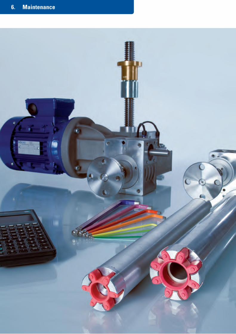
© by Nozag - 2015133
6. Maintenance

© by Nozag - 2015 134
6. Maintenance
To ensure trouble-free operation across the entire operational life right from the beginning, please always follow our operating manual.
Table of Contents Page
6.1 Fundamentals 135
6.2 General 137
6.3 Product Description 138
6.4 Constructive Installation Directives 139
6.5 Use for the Intended Purpose 140
6.6 Assembly 140
6.7 Operation 143
6.8 Maintenance 144
6.9 Spare Parts 144
6.10 Accessories 145
6.11 Miscellaneous (Modifications / Dismantling and Disposal / Document Index) 148

© by Nozag - 2015135
6.1 Fundamentals Maintenance
Safety
Safety and availabilitySafety and availability are just as important in the case of industrial systems as they are for theatre stag-es or other systems.
Construction and layoutAt the time of design and construction, pay attention to the loading capacity of the drives and system components depending on the installation situation. Design the fastening, movement and transmission elements with a factor of safety that is suitable for your system. Follow the design instructions. In safety-relevant systems, use a safety trap nut SIFA.
AssemblyCorrect and careful assembly is required for smooth and safe operation of the system. Therefore, always follow our operating instructions, which accompany every delivery. You can also find them on the Internet at www.nozag.ch
Inspection and maintenanceRegular inspection and maintenance is necessary to ensure availability. The following should be checked at the time of regular inspection: visual appearance, fastenings and joints, wear of the trapezoid thread and the lubrication state. Follow our lubrication instructions and use only the lubricants recommended by us. Also consider our automatic lubricant dispensers.
Spare PartsFor protection from production downtime in case of a long switching on time or a high load, we recommend stocking a gearbox set (incl. threaded spindles etc. and assembly drawings) either with you or your customer. Repair work on the jack is usually most economically achieved with a complete replacement.
Temperature
The ambient temperature is very important for the design of the components. Please always specify the ambient temperature and ambient conditions, especially if they are different from the normal 20°C to 25°C.
Normal temperature (-20°C to +60°C):A normal temperature range is up to approx. 60°C gearbox operating temperature. The greatest heating takes place at the shaft sealing ring and at the trapezoid thread.
Low temperature (-20°C to -40°C):Basically, the seals and most of our greases can be used up to a temperature of -40°C. But experience has shown that use below -20°C is critical. The greases become very viscous and difficult to move; especially the breakaway torque is affected. At minus temperatures, in general, all the components must be suf-ficiently dimensioned.
High temperature (+60°C to +160°C):At ambient and operating temperatures (gearbox housing) above 60 °C, we recommend gearboxes with high-temperature grease and FPM seals. In general, the operating temperature can then be up to 160°C. For high-temperature applications, we supply the corresponding heat-resistant components.
For lower and higher temperatures, please inquire about the components, ideally, with the checklist.
Foodstuffs industry
The foodstuffs industry works with a high degree of automation. On the one hand, this helps to achieve a higher standard of hygiene, and on the other, with intelligent and efficient systems, rational production becomes possible. For the foodstuffs industry, we have already manufactured various bevel gearboxes and screw jacks including accessories in stainless steel with the corresponding grease filling. In case of any requirement, please do inquire with us.

© by Nozag - 2015 136
6.1 Fundamentals Maintenance
Lubrication
Screw jacksThe screw jack is sealed and filled with a synthetic lubricant. In normal operation, the gearbox is lubri-cated for life.
Trapezoid thread spindleThe trapezoid thread spindle must be inspected regularly and re-lubricated according to the operating cycle.
Long-life systemsIn the case of long-life systems (for example, working platforms or theatre stages) the grease loses its lubrication properties after approx. 5 years. Dust and dirt enhance this effect. We recommend a complete cleaning and re-greasing after 5 years.
KGT lubricationLubricate the ball screw KGT every 500 hours of effective running period. Guide value for grease quantity approx. 1 ml per cm spindle diameter.
Other greases, foulingThe use of multi-purpose grease and other greases can significantly reduce the working and the life. In case of fouling of the spindle, it should be cleaned and regreased.
Lubrication dispensers
Nozag lubricant dispensersThe lubricant dispenser serves for providing a continuous supply of grease. The lubricant dispenser is bolted on directly at the lubrication point. It works independently and is activated upon setting the run-ning period. The lubricant level is visible at all times in the transparent housing.
Advantages■ Time-saving and cost-saving owing to automatic lubrication■ Longer life and operational safety through continuous lubrication■ One dispenser covers running periods of 1 to 12 months
Technical DataDrive system: Hydrogen-gas generation cell (dry element)Setting: continuously variable 1 to 12 monthsVolume/Weight: 60 ml/approx.115 g + 125 ml/approx.190 g, other volumes available upon requestOperating pressure: max. 5 barApplication temperature: - 20°C to + 55° C ambient temperatureApplication: the dispensers can be mounted in any position.Caution: do not subject to direct heatUsage time: within 2 years of production dateStorage temperature: recommended at 20°C +/- 5°C
Completely filled grease channels are important for reliable working. It has to be ensured that the grease channels are not blocked. Therefore, they must be completely lubricated by means of a grease gun before every commissioning of the dispensers. The lubricant dispenser can be readjusted or shut off during the dispensing period. The values on the adjusting scale disc are based on laboratory conditions. Depending on the setting and the temperature, after starting, it can take hours, and in the case of long-term settings, some days, before the first discharge of lubricant. The user must regularly inspect the working of the lubri-cant dispenser. Connecting pipes may not be longer than 0.5 m. Recommended hole diameter: 6 – 8 mm. Pipe resistances must be minimised, bottlenecks and angular bends are not permitted. The lubricant dis-penser may only be used for supplying one lubrication point. No branches should be made.

© by Nozag - 2015137
6.2 General Maintenance
6.2.1 Using the ManualThis assembly manual must categorically be followed for the integration of the screw jack in a system, so that first, the functions can be fulfilled in keep-ing with the specifications, and second, personnel and equipment protection is guaranteed.Only by strictly following this installation manual, can the safety of process and personnel be achieved.
Not complying with this manual can result in dangerous situations. If the screw jack is transferred to a third party, this manual must also be passed on.
Please contact Nozag in case of doubts or questions.
6.2.2 Supplementary Documentation■ Data sheets■ Dimension diagrams■ Catalog
This documentation can be obtained at www.nozag.ch or directly from Nozag.
6.2.3 Reference to Machinery Directives and ComplianceThe screw jacks conform to the present state-of-the-art and the applicable regulations. They fulfill the preconditions so that they can be integrated in sys-tems without problems, both functionally and from a safety standpoint.
As long as the integration of a screw jack is performed in accordance with this assembly manual, then basic system requirements enacted in the following Directives shall be deemed as having been complied with:2006/42EG Annex II (Machinery Directive)2004/108/EC (EMC Directive)
The engineering connections must be carried out in keeping with the govern-ing requirements and with the EMC Directives!
6.2.4 Qualified PersonnelThe layout, assembly, commissioning and maintenance of the screw jacks may only be carried out by personnel specially authorised, trained and in-structed in the field of electrontechnical machinery.
6.2.5 General Safety InstructionsThe operator must ensure that persons entrusted with the assembly and main-tenance have read and understood the Assembly and Maintenance Manual and follow it in every respect, in order to:■ avoid dangers to life and limb of users or third parties or to property■ ensure the operational safety of the screw jack■ exclude the possibility of usage failure through incorrect handling
Work on screw jacks may only be carried out at standstill and with sufficient safeguarding against unintentional switching on.Replaced lubricants should be disposed of in a technically correct manner and keeping within the applicable regulations.
For the integration of the screw jacks in equipment, machines or systems, it is the responsibility of the manufacturer of the equipment, machines or systems to include the specifications, instructions and descriptions as given by Nozag of the screw jacks, in his operating manual.
6.2.6 Warning and Symbols usedThe following symbols are used in this text to provide warnings of possible danger and useful additional information:
Danger to humansThis symbol indicates that non-compliance with the safety instruc-tions can result in serious bodily injury or death.
Danger to property (material)This symbol indicates that non-compliance with the safety instruc-tions can result in property damage (destruction of materials).
NoticeThis symbol indicates that there is additional useful information pro-vided here.

© by Nozag - 2015 138
6.3 Product Description Maintenance
1
16
14
4
8
5
5
8
2
3
6
7
114
4
8
5
5
8
9
13
12
10
11
7
6
32
15
15
1 Housing 2 Worm wheel 3 Worm 4 Bearing cover
5 Axial grooved ball bearing 6 Grooved ball bearing 7 Oilseal 8 X-ring/O-ring
9 Lubrication nipple for spindle 10 Protection tube 11 End cover 12 Unscrewing protection
13 Anti-rotation lock 14 Spindle 15 Spindle guide 16 Duplex nut
Non-rotating spindle NSE...-S...The worm wheel is provided with a female thread and converts the rotational movement into an axial movement of the spindle, when the latter is prevented from rotating (through its design or by means of an anti-rotation protection in the protection tube).
Rotating spindle NSE...-R...The spindle has a fixed connection to the worm wheel and rotates with it. The nut therefore screws itself up and down.
This manual is applicable to all screw jacks of the NSE series in the standard versions manufactured by Nozag in the sizes 2, 5, 10, 25, 50 and 100, as well as for special types, in consultation with Nozag.

© by Nozag - 2015139
6.4 Constructive Installation Directives Maintenance
6.4.2 Operating TemperaturesThe temperature behaviour is dependent on the ambient temperature and on self-heating during operation under load. The self-heating can be reduced through favourable construction measures for fast dissipation of heat.
The jack can quickly become hot during operation under load. Therefore, in such a case, sufficient contact protection should be provided. Please note the following temperature ranges and the corresponding notes:
-40°C to -20°C low temperature The standard seals and greases can all be used up to -40°C. However, the breakaway torque and the wear both increase significantly. In general, at low tem-peratures, all the components should be dimensioned for greater safety. Please contact our technical de-partment.
-20°C to +60°C normal temperature The highest heating is normally to be observed at the worm shaft and at the trapezoid threaded nut and it should never go out of this temperature range. The range limits may not be used as the nor-mal operating points.
+60°C to +160°C high temperature In case of ambient or operating temperatures in this range, only jacks equipped with high-temperature grease and FPM seals may be used. Please contact our technical department.
6.4.3 Measures to be Taken in Case of Increased RiskThe trapezoid threaded nut is subject to continuous wear owing to the existing friction. The wear of the trapezoid thread in the worm wheel or in the nut must be checked at suitable intervals depending on the duty cycle.
As soon as the axial distance between the trapezoid thread nut and the spindle is more than 20% of the thread pitch, the gearbox or the worm wheel (S-Version) or the nut (R-Version) must be replaced.
The wear can be checked with a safety trap nut and by monitoring it.
Essentially, a screw jack in the R-Version should not be subjected to tensile loads, since the trapezoid thread spindle is subject to a cyclical bending stress and can break without any warning. If this type of in-stallation cannot be avoided, then, under increased safety require-ments (such as in stage construction, suspended loads, …) the load must without fail be secured by an external trapping device.
Upon request Nozag shall provide suitable solutions for this.
A screw jack must never hit a mechanical stop, since the forces that then occur could reach a multiple of the rated load. All warranties as well all liabilities of Nozag shall be rendered null and void in such a case.
There are various moving parts freely accessible on a screw jack, such as the nut, spindle and shaft ends, which can mean great personal danger while in operation. The systems integrator is re-sponsible for ensuring protection against accidental contact in the course of operation.
The protective cap SK from Nozag can be used for the free end of the driving shaft as protection from accidental contact.
In general, the construction instructions and design procedures listed in our catalogue should be followed.
6.4.1 General Design MeasuresThe load bearing capacity of the drives and system components varies widely according to the installation situation and the operating duration. The limits specified in the data sheets must not be exceeded under any circumstances.
Screw jacks are basically not suitable for continuous operation under load. The maximum operating duration depends on the load being moved and must not exceed the limit values according to the ED-diagram on the relevant data sheets.
The duration of operation can be significantly increased by using a ball screw spindle instead of the trapezoid thread spindle. Particular attention must be paid to the evenness, as well as the parallelity and angularity of the mounting face of the gearbox, nut and guides with respect to one another.
Lateral forces must be absorbed by additional guides. The play between the spindle and the integrated guide bushings is between 0.2 and 0.6 mm depending on the size. This is only a secondary support and does not replace a guiding system.
As a minimum distance of the mov-able parts to the fixed parts in the direction of lifting, we recommend in the case of trapezoid spindles, the thread pitch times one, and in the case of ball threaded spindles, the thread pitch times two. This distance must not fall below this limit.

© by Nozag - 2015 140
The screw jacks of the NSE serve to convert a rotational movement into a lin-ear one, in order to then carry out controlled and regulated pushing and pulling movements. In addition, they can be used in all installation positions in gen-eral mechanical engineering, under normal ambient conditions, in compliance with the operating limits and always in consideration of all the technical data, in accordance with the applicable data sheets.
In case of use with suspended loads, special additional measures must be taken in order to ensure sufficient protection for persons and property at all times.
Other uses, or any use over and above those described a proper usage, shall be considered as improper and can result in dangerous situations.
Adjustments may be necessary in case of special requirements, such as those existing, for example in the food industry, or where extreme ambient conditions prevail. In such cases, it is neces sary to clarify all specific details with Nozag.
A screw jack may only be brought into operation when it is ensured that the machine or plant, in which it has been installed, conforms to the EU Machinery Directive’s regulations and to corresponding national standards and specifications.
Screw jacks in ATEX design are special versions and should be discussed with Nozag.
6.6.1 Guide Values for Screw Tightening TorquesInformation based on VDI 2230, edition 2003: Maximum permissible tighten-ing torques for hexagon socket screws ISO4762 and screws with similar head strength and head bearing surface, of the strength class 8.8 at 90% exploita-tion of the elastic limit Rel. / 0.2%-yield point Rp0.2. The table shows the per-missible maximum values and does not contain any further safety factors. It assumes a knowledge of the relevant directives and design criteria.
Maximum tightening torques (Nm) for strength class 8.8 and a total coeffi-cient of friction of µges = 0.12:
Dealing with the guide valuesFriction µges
The friction coefficient shows scatter, since it is depending upon many fac-tors, such as the material pairing, the surface quality (roughness depth) and the surface treatment. If the total friction is less, a smaller tightening torque should be selected. The main cause of fractures is an overestimation of total friction factors.
Strength classThe strength class refers only to the screw and is determined according to ISO 898/1.
Tightening torque MA
These are guide values and do not substitute a recalculation according to VDI2230. In case of additional tensile forces acting centrally or eccentrically, as well as statically or dynamically on the screws, the tightening torques and/or loading forces should be reduced to such an extent that the maximum per-missible load on the screws is not exceeded.
Screw-in depthThese guide values assume a screw-in depth of 1.4 x nominal diameter (of the screws) in the aluminium housing.
Thread size Tightening torque MA
M4 3
M5 6
M6 10
M8 25
M10 48
M12 84
M16 206
6.5 Use for the Intended Purpose Maintenance
6.6. Assembly Maintenance

© by Nozag - 2015141
6.6 Assembly Maintenance
6.6.3 SpindleWhile assembling the spindle and fastening the spindle end, care must always be taken, first, that the spindle is in alignment with the nut, second, that the housing is at right angles to the resting surface of the housing and third, that it is parallel to any guide-way that may be present. This must be ensured during the entire opera-tion, so that the jack does not have to absorb lateral forces in any situation.
In the R-version, the spindle can be installed in the housing from both sides. Thus, depending on the loading direction, the load can be ide-ally transmitted into the housing and not into the bearing cover.
In the R-version, the central screw or nut for spindle fastening must be installed with a suitable thread adhesive (e.g. Loctite 243) and the correct torque. Otherwise, in case of tensile loading, there is a danger that the spindle might be pulled out of the housing!
In this context, the instructions of the thread adhesive manufacturer must be followed without fail.
Tightening torques (Nm) for spindle central screw or nut in the R-version:
6.6.4 NutThe nut must be mounted concentri-cally with the spindle, and the bearing surface must be at right angles to the spindle axis, so that uniform resting in all thred turns is ensured. The calotte disks NSE...-KS can be used for com-pensating angle errors up to ±3°.
Lateral loads and alignment errors should be avoided, since they can have a very negative effect on the life of the support nut.
In order not to subject the screws to tensile loads as far as possi-ble, the load must always be supported against the nut flange.Should this not be possible, the threaded joint must be designed in accordance with VDI2230 and constructed accordingly.
The 4 threaded holes or the 3 through holes in the housing can be used for fastening.
6.6.2 HousingShould the specified screw-in depths not be exploited for fasten-ing the housing or the prescribed tightening torques not be com-plied with, the certainty of the screws getting pulled out under tractional stress is reduced. If the screws are stressed to more than 50% of the rated tensile load, the screw connection must be recalculated according to VDI2230. A decision can thus be made whether the existing safety is adequate in the relevant application.
In order to avoid a tensile load of the screws, the bearing surface must be arranged as follows, depending on the load:
Main load: Pressure from top > support below
main load: tension upwards > support above
NSE2 NSE5 NSE10 NSE25 NSE50 NSE100
2 5 10 15 50 100
nut screw screw screw screw screw
M6 M8 × 20 M10 × 30 M14 × 40 M20 × 50 M42 × 3
4-6 9-14 19-30 55-90 150-240 550-990

© by Nozag - 2015 142
6.6 Assembly Maintenance
6.6.5 Safety trap nutThe gap X between the nut and the safety trap nut corresponds to half the trapezoid thread pitch (= tooth thickness) in the new state. The wear of the nut causes a correspond-ing reduction of the gap, which can be monitored.
The safety trap nut works in one direction only and therefore, at-tention must be paid to the correct arrangement!R-Version: viewed in the direction of the load after the nutS-Version: viewed in the direction of the load, before the nut
6.6.6 Ball Screw KGTThe same points as described in 6.6.3 and 6.6.4 have to be followed.
The delivery is always in the form of an assembled spindle/nut unit and it must not be taken apart under any circumstance, otherwise the balls will fall out.
If dismantling is necessary, in the R-version, the nut can be re-moved by using a mounting sleeve. The sleeve is used like an ex-tension of the spindle and prevents the balls from falling out.
Ball screws are not self-locking, which is why a braking motor or a spring-loaded brake FDB is necessary. A ball screw in the S-version is generally as-sembled with an unscrewing protection AS by default.
6.6.7 Protection TubeThe protection tube can-not absorb any lateral force in the standard version. The same ap-plies during transporta-tion: the jack must not be supported at the protec-tion tube end.
6.6.8 LubricationScrew jacks are supplied in an opera-tionally ready state and are lu bricated for life under standard conditions.
Nozag provides the spindles in the S-version pre-greased ready for use, with a protection tube. Without a protection tube, or in the case of the R-version, the spindles are delivered without grease owing to the danger of soiling.
Before the first trial run, the ungreased spindles must be cleaned and generously lubricated over theire entire length with a grease that adheres well.For a long life, use the greases that are suggested by Nozag.
6.6.9 Direction of Rotation and Movement
Before a motor trial run, a check should first be carried out as to whether all the coupled screw jacks have the same direction of move-ment. When using bevel gearboxes, the direction of movement of the screw jacks can be changed, simply by turning the bevel gear (however, this only applies to the D-version with 3 shafts).
6.6.10 Levelling and Trial RunIn the case of coupled screw jacks, the individual gearboxes can be levelled with the help of couplings or connecting shafts. The levelling is done under load by loosening and turning the coupling or the shaft through 120°. For con-tinuous (stepless) variable height settings, a clamping hub coupling KNK or a connecting shaft VW can be used.
Screw jacks equipped with ball screws or multi-start trapezoid thread spindles are not self-locking and must therefore be secured during assembly.
During the trial run, the assembly quality can be indirectly checked by a con-tinuous measurement of the motor current drawn. If an increased drawn cur-rent is determined, the fastening screws should be loosened and a new trial run initiated. Non-uniform force requirements and wear tracks on the spindle indicate the presence of alignment errors.
Before and after the trial run, all the screwed joints must be checked and tightened correctly.
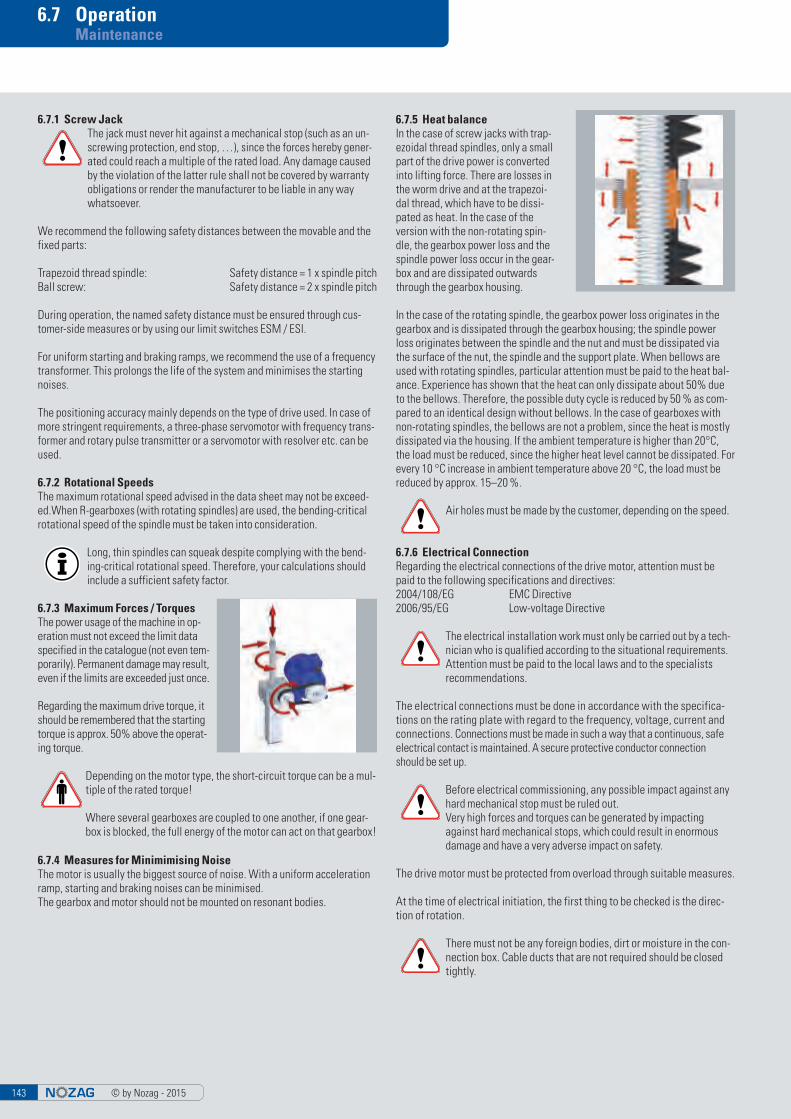
© by Nozag - 2015143
6.7 Operation Maintenance
6.7.1 Screw JackThe jack must never hit against a mechanical stop (such as an un-screwing protection, end stop, …), since the forces hereby gener-ated could reach a multiple of the rated load. Any damage caused by the violation of the latter rule shall not be covered by warranty obligations or render the manufacturer to be liable in any way whatsoever.
We recommend the following safety distances between the movable and the fixed parts:
Trapezoid thread spindle: Safety distance = 1 x spindle pitchBall screw: Safety distance = 2 x spindle pitch
During operation, the named safety distance must be ensured through cus-tomer-side measures or by using our limit switches ESM / ESI.
For uniform starting and braking ramps, we recommend the use of a frequency transformer. This prolongs the life of the system and minimises the starting noises.
The positioning accuracy mainly depends on the type of drive used. In case of more stringent requirements, a three-phase servomotor with frequency trans-former and rotary pulse transmitter or a servomotor with resolver etc. can be used.
6.7.2 Rotational SpeedsThe maximum rotational speed advised in the data sheet may not be exceed-ed.When R-gearboxes (with rotating spindles) are used, the bending-critical rotational speed of the spindle must be taken into consideration.
Long, thin spindles can squeak despite complying with the bend-ing-critical rotational speed. Therefore, your calculations should include a sufficient safety factor.
6.7.3 Maximum Forces / TorquesThe power usage of the machine in op-eration must not exceed the limit data specified in the catalogue (not even tem-porarily). Permanent damage may result, even if the limits are exceeded just once.
Regarding the maximum drive torque, it should be remembered that the starting torque is approx. 50% above the operat-ing torque.
Depending on the motor type, the short-circuit torque can be a mul-tiple of the rated torque!
Where several gearboxes are coupled to one another, if one gear-box is blocked, the full energy of the motor can act on that gearbox!
6.7.4 Measures for Minimimising NoiseThe motor is usually the biggest source of noise. With a uniform acceleration ramp, starting and braking noises can be minimised.The gearbox and motor should not be mounted on resonant bodies.
6.7.5 Heat balance In the case of screw jacks with trap-ezoidal thread spindles, only a small part of the drive power is converted into lifting force. There are losses in the worm drive and at the trapezoi-dal thread, which have to be dissi-pated as heat. In the case of the version with the non-rotating spin-dle, the gearbox power loss and the spindle power loss occur in the gear-box and are dissipated outwards through the gearbox housing.
In the case of the rotating spindle, the gearbox power loss originates in the gearbox and is dissipated through the gearbox housing; the spindle power loss originates between the spindle and the nut and must be dissipated via the surface of the nut, the spindle and the support plate. When bellows are used with rotating spindles, particular attention must be paid to the heat bal-ance. Experience has shown that the heat can only dissipate about 50% due to the bellows. Therefore, the possible duty cycle is reduced by 50 % as com-pared to an identical design without bellows. In the case of gearboxes with non-rotating spindles, the bellows are not a problem, since the heat is mostly dissipated via the housing. If the ambient temperature is higher than 20°C, the load must be reduced, since the higher heat level cannot be dissipated. For every 10 °C increase in ambient temperature above 20 °C, the load must be reduced by approx. 15–20 %.
Air holes must be made by the customer, depending on the speed.
6.7.6 Electrical ConnectionRegarding the electrical connections of the drive motor, attention must be paid to the following specifications and directives:2004/108/EG EMC Directive2006/95/EG Low-voltage Directive
The electrical installation work must only be carried out by a tech-nician who is qualified according to the situational requirements.Attention must be paid to the local laws and to the specialists recommendations.
The electrical connections must be done in accordance with the specifica-tions on the rating plate with regard to the frequency, voltage, current and connections. Connections must be made in such a way that a continuous, safe electrical contact is maintained. A secure protective conductor connection should be set up.
Before electrical commissioning, any possible impact against any hard mechanical stop must be ruled out.Very high forces and torques can be generated by impacting against hard mechanical stops, which could result in enormous damage and have a very adverse impact on safety.
The drive motor must be protected from overload through suitable measures.
At the time of electrical initiation, the first thing to be checked is the direc-tion of rotation.
There must not be any foreign bodies, dirt or moisture in the con-nection box. Cable ducts that are not required should be closed tightly.

© by Nozag - 2015 144
6.8 Maintenance Maintenance
6.9 Spare Parts Maintenance
6.8.1 Lubrication The worm gearboxes are lubricated for life under standard conditions.The lubrication consumption is con-centrated above all, on the trapezoi-dal screw. It should be re-lubricated regularly, depending on the duty cycle. Since the lubrication require-ment of a trapezoidal screw depends on very many factors, no general guidevalues can be specified for the required lubrication intervals. We recommend that the user starts with a weekly interval; a weekly inspec-tion of the spindle should then be carried out. The lubrication intervals can thus be individually matched to the prevailing conditions.
During dry running, the nut is subjected to intense wear and can, in addition, become extremely hot very quickly.
Ball screws KGT should be re-lubri-cated after every 300 hours of effec-tive operating time. A guideline val-ue of 1 ml per cm spindle diameter can be taken for the grease quantity.
After about 5 years, the grease loses its lubricating properties. Dust and dirt increases this effect. Therefore in the case of long-life systems, a complete cleaning and re-greasing is necessary after 5 years. If the spindle is dirty, it must be cleaned and regreased to avoid excessive wear and damage.
Recomended grease Blasolube 306(other lubricants on request)
Grease amount per gearboxNSE2 20 cm3 NSE25 100 cm3
NSE5 25 cm3 NSE50 420 cm3
NSE10 40 cm3 NSE100 800 cm3
Our lubricant dispenser SSG can be used for automatic lubrication. The lubricant dispenser is screwed on in place of the grease nipple and continuously supplies grease to the lubrication point. The dis-pensing duration can be set continuously variable from 1 to 12 months and the grease quantity varies according to the SSG-size between 0.08 – 8.3 ml/day.
6.8.2 Checking WearThe trapezoid thread in the worm wheel or in the nut is subject to continuous wear owing to the existing friction, which depends on many factors and can-not be predicted. We recommend that at the beginning, the axial play should be checked after just a few hours of effective deployment. Thereafter, the inspection interval can be gradually adjusted depending on the results.
As soon as the axial play in the trapezoid thread nut corresponds to more than 20 % of the thread pitch, the gearbox respectivly the worm wheel (S-Version) or the nut (R-Version) must be replaced.
The wear can be checked with a safety trap nut and by monitoring it. For sim-plified monitoring, Nozag offers, upon request, mechanical (manual buttons) and electrical (inductive sensor) aids.
Except for standard machine elements that are commonly available commer-cially, Nozag original spare parts must be used. Warranty entitlements as well as liability commitments shall be rendered null and void if third-party, imita-tion or non-approved components are used instead.
In order to prevent unwanted production downtimes, during long duty cycles or high loads, it is recommended to keep a complete gearbox (incl. threaded spindle, nut, …) on standby. New seals must always be used for repair.
Repair work is usually most economically achieved by completely replacing of the jack.

© by Nozag - 2015145
6.10 Accessories Maintenance
6.10.1 BellowsThe ZD-dimension must not be underrun and the AZ-dimension must not be exceeded. These dimensions can be viewed in our main catalogue.
It must be remembered that the bellows may not touch the spindle, otherwise, there is a danger of the bellows getting destroyed.
Air holes must be made by the customer, depending on the speed.
Our support rings STR can be used to prevent contact between the spindle and bellows in case of longer strokes or horizontal installation.
The maximum duty cycle of a jack with rotating spindle (R-Version) is reduced by about 50% owing to the heat-insulating action of a bellows.
6.10.2 Spiral SpringThe spiral spring is subject to a great deal of tension and is tied up with a securing wire. This securing wire may only be opened with extreme care, once the spiral spring has been pushed onto the spindle and the movable part of the machine has been compressed to such an extent, that both ends of the spiral spring are almost in contact.
Centring flanges should be provided for positioning the two ends of the spiral spring, which permit the rotational movements of the springs. The spring must be able to move freely and must not be fastened under any circumstances.In case of vertical deployment of the spiral spring, the large diameter should be at the top, so that, as far as possible, no foreign bodies (e.g. chips) can enter the coil openings.
In case of a horizontal installation of the spiral spring, for the same reason, the large diameter should be in the area where the chips are most prevalent.Regular maintenance is necessary. Depending upon the degree of contamina-tion, the spiral spring should be cleaned daily or weekly and then coated with a light film of oil. We recommend the Longlife Spray Oil W44T, which you can also obtain from us.
Spiral springs must preferably be used in oil-containing environ-ments. If fine particles or dust are generated (especially in case of grinding dust), spiral springs are not suitable. For these cases, the use of bellows is recommended.
6.10.3 Spindle End Attachments: BF, GK, KGK and SLK
Fastening flanges, fork heads, ball joints and pivot bearing heads for the S-gearbox are screwed onto the spin-dle ends. After setting the position, these attachments should be fixed by means of a lock nut, stud screw and a suitable thread adhesive (e.g. Loctite 243). The securing must be done care-fully and checked.
The fixations are not tightened at the time of delivery.This gives the user the possibility for exact positioning.
When tightening the lock nut and the stud screw, the following maximum tightening torques in Nm should be maintained:
Owing to the low efficiency of a trapezoidal spindle and the ratio of the gearboxes, the twisting torque reaches a multiple of the motor torque. With enhanced safety requirements, a positive anti-rotation lock is recommended as being indispensable.
6.10.4 Flange Bearing FLWhen assembling the flange bearing at the spindle end, care must be taken that it aligns with the gearbox/spindle/nut, otherwise, the spindle is subject to a cyclical bending stress and can break without previous warning.
The flange bearing is not suitable for absorbing radial forces.At the time of assembly, it must be ensured that there is enough axial play, so that the spindle can expand freely when it heats up.
6.10.5 Motor Adapter MOACheck the length of the fastening screws for the motor. The motor can get damaged if excessively long screws are used!The coupling can be checked through the viewing hole and fixed.
In the following motor-gearbox combinations, with Nozag stand-ard couplings, an additional motor adaptor ring MOAR is neces-sary:
NSE10 - IEC80NSE25 - IEC90NSE50 - IEC100 - IEC112
The motor adapter ring can be dispensed with when using a rotary encoder DIG.
NSE2 NSE5 NSE10 NSE25 NSE50 NSE100
Locking nut
6 Nm(M8)
20 Nm(M12)
45 Nm(M14)
140 Nm (M20)
440 Nm (M30)
700 Nm (M42x2)
Stud screw
1 Nm (M3)
2.5 Nm (M4)
5 Nm (M5)
5 Nm (M5)
8 Nm (M6)
20 Nm (M8)

© by Nozag - 2015 146
6.10 Accessories Maintenance
6.10.6 Three-phase MotorThe motors normally have a terminal board with 6 terminals and an earth lead terminal in the terminal box. By shifting the connecting link, the sta-tor winding can be connected in star or delta formation.The star/delta starting process is not suitable for lifting jack systems, since the full torque is required right from the start.
Basically, we recommend the use of 4-pole motors with a maximum rotational speed of 1400 rpm. Higher rotational speeds are only possible with the ex-pressed permission of Nozag.
The maximum motor torque can reach a multiple of the rated torque for a short time. If required, this must be limited using a frequency converter.
When operating with a frequency converter, it must be remem-bered that for prolonged operation below 25 Hz, an external fan is required for sufficient cooling of the motor. The separate documentation for the motor must be followed without fail.
6.10.7 Coupling / Connecting Shaft
Beware of the axial alignment of the shafts being connected. Despite a certain elasticity of the coupling or the connecting shaft, the deviations should to be kept to a minimum. The maximum errors allowed can be seen in our catalogue. The standard couplings 035 to 190, as well as the connecting shafts LJ and GX must be pushed onto a shaft end with feather keys and thereafter, secured against axial displacement by tightening the threaded pin over the feather key.The clamping hub coupling KNK and the connecting shaft VW can be radi-ally mounted through the partitioned clamping hubs and the feather key can be omitted. The clamping screws are not allowed to be re-placed by a different quality, and for securing torque transmission, must be tightened according to the fol-lowing table:
Tightening torques (Nm) for clamping bolts:
6.10.8 Limit Switch: ESM, ESIThe working of the controller in con-junction with the limit switches must be so designed that a mechani-cal stop is completely avoided. Test the limit switch function before the motor trial run. If the after-running of the motor does not ensure a com-
plete stillstand, a braking motor should be used. This can especially take place in the case of multi-start threaded spindles and ball screws.
The protection tube has a wall thickness of only 2 mm,depending on the gearbox size. Therefore, the M5-fastening screws may be tightened with a maximum of 2Nm, so that the thread in the tube is not destroyed. In no case should screws longer than those sup-plied be used, since screws reaching too far into the protection tube could collide with the unscrewing protection.
6.10.9 Spring-loaded Brake FDBWhen re-lubricating the spindle, the friction sur-face of the spring-loaded brake must be protected from dirt without fail. Under no circumstances may oil or grease reach the friction pad. Small amounts of dirt can ad-versely affect the work-ing of the brake.
The maximum permissible limiting temperature of the spring-loaded brake is 145°C. When using a spring-loaded brake or a braking motor in combination with a frequency converter, activate the brake separately. The separate docu-mentation for the spring-loaded brake must be followed without fail.
6.10.10 Handwheel HRThe handwheel is pushed onto the shaft with a feather key, at least to the extent that it is flush with the shaft end, and must be secured with a stud screw over the feather key or with a cross-hole and pin.
If a handwheel is combined with a motor, no handle must be screwed in because of the imbalance. During motor operation, the handwheel must under no circumstances be accessible.
6.10.11 Calotte disks KS for Duplex Nuts DMN
If the joint surface for the nuts is not at right angles to the spindle axis, the calotte disks KS can be used to compensate an error of up to ±3° on the fastening surface.
When tightening the screws, care must be taken that the two large disks are parallel to one another, in order to avoid excessive tilting torque of the screw heads.
The calotte disks are not suitable if the angle can change during operation.Parallelism errors of spindles to one another and to guides cannot be compensated.
KNK02 KNK06 KNK15 KNK30 KNK45 KNK80
VW28 VW35 VW50 VW60 VW76 VW90 VW120
4 8 15 35 70 120 290

© by Nozag - 2015147
6.10 Accessories Maintenance
6.10.14 Cardan Pin KBThe interface for the cardan pin must be made as rigid as possible, so that the pin cannot give way under load and the pins, always to be used in pairs, must be arranged coaxially, otherwise, a uniform positioning in the bearing bushes is not ensured, which results in excessive wear.The pins should be fastened in such a way that there is only a minimal play to the bearing bushes on the face side.
Above all, in combination of cardan pins with cardan adapter plates at the gearbox, a rigid positioning construction for the car-dan pins is important. The pins must also remain coaxial (± 0.3°) under load, since otherwise, the fastening screws of the cardan adapter plates do no longer provide the same safety under the additional forces that occur.
The screw joint of the cardan pins must be designed with particu-lar care and recalculated according to VDI2230. The resting con-tact surfaces should be so designed that shearing forces are avoided as far as possible.
6.10.15 Support Tube STRWith a support tube, large additional forces can act on the gearbox and the spindle, and therefore, for a swivel bearing solution, whenever possible, the cardan adapter should be preferred!
A horizontal arrangement is the least favourable, since almost the entire dead weight has to be absorbed by the short spindle guide in the gearbox. Therefore, the following maximum stroke lengths in mm apply:
The kink length calculation must be carried out without fail des-pite the already restricted stroke lengths. If the load is a pressure load, the maximum stroke length can be even shorter.
6.10.12 Carrier Flange TRMFLThe carrier flange serves for an ec-centric fastening of a load, where by this load must have its own stable linear guide, so that solely an axial force acts on the nut and the carrier flange.
The torques that occur must be absolutely absorbed by an external guide, since the fastening screws could get overloaded with an additional tilting torque and the nut would be subject to significant wear.
6.10.13 Cardan Adapter for Gearbox KAL, KAK and cardan Nut KM
The swivelling axis should preferably be arranged parallel to the drive axis, so that no additional torque acts on the spindles owing to the motor weight. Particular attention must be given in case of non-horizontally placed spin-dle axis, long strokes and large motors, otherwise, increased wear at the nut and the spindle will have to be ex-pected. The pivot bearing bushings are maintenance-free and need not be lubricated. However, a one-off lubrica-tion at the time of assembly improves the running-in characteristics as well as the friction coefficient. For the shaft, a tolerance zone h9 and a sur-face roughness of Ra=0.8 is recom-mended.
The cardan adapter must always be mounted in such a way that the fastening screws are not stressed in the main load direction.If this is not possible, the load that occurs may not exceed 50% of the rated load. Otherwise, calculations for the screwed joint will have to be carried out again with the conditions applicable in the respective application, in accordance with VDI2230.
NSE2 NSE5 NSE10 NSE25 NSE50 NSE100
100 200 250 400 500 600

© by Nozag - 2015 148
6.11 Miscellaneous Maintenance
6.11.1 ModificationsThe screw jack and the accessories may not be modified without Nozag’s agreement, neither from a technical safety standpoint, nor a constructive standpoint. Any violation of the latter rule shall free Nozag from all warranty or liability obligations whatsoever.
6.11.2 Dismantling and DisposalAt the time of dismantling, before loosening any screws, please ensure that all the loads have been secured. The local community waste disposal regula-tions must be observed.
6.11.3 Document IndexProduct data sheets and catalogues are downloadable in PDF format from our website www.nozag.ch or can be obtained free of charge from Nozag.

© by Nozag - 2015149
Years of experience> over 40 years of producing gear components> 35 years of experience in the development and construction in gearbox manufacturing
Theory in honor> on our performance testing station for gearboxes, your prototype can be tested to your load cycle specifications
From your idea to the finished assembly – everything from one source
High series safety, thanks to performance tests> many factors can be simulated, like different and changing torques, axial forces, radial forces, speeds and much more.
Complete logistic chain for your series product> sourcing, manufacturing of individual components> reliable, flexible assembling> quality control> on schedule delivery to your guidelines> for yearly agreements, temporary storage possible> delivery in swap containers
Technische Beratung Konstruktion Prototypenherstellung Test auf Prüfstan
d
Log
istik
M
ontage
Technische Beratung Konstruktion Prototypenherstellung Test auf Prüfstan
d
Log
istik
M
ontage
Technische Beratung Konstruktion Prototypenherstellung Test auf Prüfstan
d
Log
istik
M
ontage
technical design
noitcudorp noitats gnitset
no
lo
gist
ics
asse
mbly
advice
epytotorp tset ecnamrofrep
Technische Beratung Konstruktion Prototypenherstellung Test auf Prüfstan
d
Log
istik
M
ontage
7. Customer specific assemblies/gearboxes Individual products and services

© by Nozag - 2015 150
1 spur gear drive with rack as a positioning indicator
2 Nozdrive® as an elevating drive
3 worm drive for switch activation (energy transfer)
4 Screw jacks with transverse guidance
7. Customer specific assemblies/gearboxes Individual products and services
1 2
3 4

© by Nozag - 2015151
7. Customer specific assemblies/gearboxes Individual products and services
5 Customer-specific spur gear boxes
6 bevel gearbox with combined spur gear drive for wheelchair drive mechanism
7 spur gearbox with a dimension of: 390 x 255 x 120 mm
8 spur gearbox for drainpipe robot
5 6
7 8

© by Nozag - 2015 152
7. Customer specific assemblies/gearboxes Individual products and services
9 «ALL-IN» Ball Screw for Common Lifting Situations
10 Nozdrive® for trapezoidal screw tech-nique – configure your applications mass
11 SHC – reliable in any weather
12 spur gearbox CHC
9 10
11 12

© by Nozag - 2015153
Components made from your drawing
Take advantage of our strengths and skills■ our own production in CH-8330 Pfäffikon■ high flexibility■ Swiss quality■ short delivery times■ one partner for the sourcing of finished components■ even small batch series■ thermal or galvanic treatment
Gears from our own production■ module from 0.3 to 8mm■ up to Ø 500 mm■ material: steel, stainless steel, bronze, brass, plastic,
plastic with steel-core, laminated fabric, etc.■ even helical toothed, hardened and ground
Upon request we take over the logistics for you■ call orders with duration of up to 12 months■ delivery in swap containers
You benefit of■ reasonable price due to larger series■ short delivery time for each call-off■ smaller warehouse costs■ no material price fluctuations
1 bore bigger? 2 keyway? 3 threaded bore? 4 lathe off hub?
123
1 2 4
7. Individual gear components Individual products and services

© by Nozag - 2015 154
Your advantages at one glance
> 3D CAD data download from www.nozag.ch> support for layout and dimensioning> drive systems and components from our own production> ready to install processing of standard components according to your needs
> special execution to your specifications out of our own production> most standard components available from stock> flexibility and quality thanks to our own production> various materials such as steel, stainless steel, bronze, brass, plastic, laminated fabric
1 Spur gears Module 0.3 to 8■ straight toothed, helical toothed■ upon request, hardened and ground
2 Bevel gears up to Module 6■ straight toothed, helical toothed■ upon request, hardened and ground
3 Trapezoidal screws and nuts■ for longer life, also available with surface treatment
4 Worms and worm wheels
5 Standard racks
6 Chains and sprockets■ standard chains■ special chains even for difficult
applications or requirements
7 Connecting shafts■ torques up to 1060Nm■ speeds up to 4000min-1
■ lengths up to 3000mm■ radial assembly
8 Internal ring gear Module 1 to 2
7. Overview of further product range Individual products and services
2
6
3
7
4
8
1
5

© by Nozag - 2015155
Our high quality shafts are used in most areas of industry, such as for textile, printing, packaging industry, machine tools, machinery for the food industry, measuring and control systems, linear systems, optical and medical equip-ment, etc.
Hardened precision steel shafts from stock or machined ready for installation
Flexible■ precision shafts at short call from stock■ thanks to our own production, fast processing to your drawings
Quality under our own control■ long time production specialists in high precision mechanics
End machining on ball screwFurther processing of a precision shaft on grinding machine
7. Hardened and ground precision shafts h6 Individual products and services

© by Nozag - 2015 156
7. Hardened and ground precision shafts h6 Individual products and services
Overview of Types and diametersAll precision steel shafts and tubes are available, in production lengths or cut to length, from stock. Further diameters and tolerances available on request.
Applications / operational areasWE suitable for upper grade applications within the field of linear guides, guide pillars, roller levelling and holmsCWE suitable for upper grade applications within the field of linear guides, guide pillars, roller levelling and holmsXWE suitable for upper grade applications within the field of linear guides, shafts and guide pillars with demand for resistance to corrosionHWE suitable for upper grade applications within the field of linear guides, guide pillars and holms
The following processing can also be done to hardened precision shafts
Here are some examples
plunge cut for retaining ring DIN 471
90° plunge cut
threaded pin with thread runout
threaded pin with undercut
face side tapped hole face side tapped holewith protective centre
keyway 90° counter bore
spanner flats clamping surface
radial tapped hole
tapped holeon a pitch circle
pin pin with threaded pin
Description External-Ø in mm, tolerance h6, ground, polished Ra <= 0.30
5 6 8 10 12 14 15 16 18 20 25 30 35 40 45 50
WE standard precision steel shaftmaterial No. 1.1213inductively hardened HRC 60-66
CWE chrome plated precision steel shaftmaterial No. 1.1213inductively hardened HRC 60-66chrome plated to size 10 ± 5 microns
XWE precision stainless steel shaftmaterial No. 1.4112inductively hardened HRC 53-59
HWE precision steel tubematerial No. 1.0601inductively hardened HRC 60-66
internal-Ø 4.0 7.0 14.0 15.4 18.0 26.0

© by Nozag - 2015157
8. General terms and conditions
Our general terms and conditions of business apply to, without exception, all our services and products. They are available using the links given below and can be downloaded or obtained from us by emailing us at [email protected]. Terms and conditions of the customer that contradict them have no validity.
Switzerlandwww.nozag.ch/en/agb (TOC)
Printing errors and errors like dimension errors etc. are excepted. We reserve the right to make technical changes and improvements. The latest drawings, which are checked and signed off by both partners with our order confirmation, apply.
Protection mark for restricting the use of documentsAll rights relating to the documentation exclusively remain with Nozag Ltd. Their purpose is limited to being read. Except for the case Nozag Ltd. has granted its written authorization, all other uses of such documentation like their publication (i. e. internet), their duplication and distribution, are prohibited. All rights that are related to the drawings, plans, products and logos described in the documentation (i. e. intellectual property, patents, design, trademark, company name) exclusively remain with Nozag Ltd. as latter’s reserved property. All rights reserved.

© by Nozag - 2015 158
8. General terms and conditions
It couldn’t be easier:www.nozag.ch
■ Userfriendly catalog. If required, download individual catalog pages for your documentation
■ 3DCAD download from the entire range of Nozag products
If you wish to be advised or supported in any way, we will be pleased to do this by phone or on site.
Nozag-Online
We offer our Tender documentation. ■ Successful solutions within a short time■ Standard program■ Systems program (Bevel gearboxes / 3phase motors)
Erfolgreiche Lösungen in kurzer Zeit
Programm Norm
Programme Standard
Standard Program
Vertretungen
Representations
Representations
Schweiz / Suisse / Switzerland
Nozag AG
Barzloostrasse 1
CH-8330 Pfäffikon/ZH
Telefon +41 (0)44 805 17 17
Fax +41 (0)44 805 17 18
Aussendienst Westschweiz
Telefon +41 (0)21 657 38 64
www.nozag.ch
Deutschland / Allemagne / Germany
Nozag GmbH
Telefon +49 (0)6226 785 73 40
Fax +49 (0)6226 785 73 41
www.nozag.de
Frankreich / France / France
NOZAG SARL
Telefon +33 (0)3 87 09 91 35
Fax +33 (0)3 87 09 22 71
www.nozag.fr
>
>
>
Niederlassungen
Filiales
Subsidiaries
Australien / Australie / Australie
Mechanical Components P/L
Telefon +61 (0)8 9291 0000
Fax +61 (0)8 9291 0066
www.mecco.com.au
Belgien / Belgique / Belgium
Schiltz SA/NV
Telefon +32 (0)2 464 48 30
Fax +32 (0)2 464 48 39
www.schiltz-norms.be
Vansichen, Lineairtechniek bvba
Telefon +32 (0)1 137 79 63
Fax +32 (0)1 137 54 34
www.vansichen.be
China / Chine / China
Shenzhen Zhongmai Technology Co.,Ltd
Telefon +86(755)3361 1195
Fax +86(755)3361 1196
www.zmgear.com
Estland / Estonie / Estonia
Oy Mekanex AB Eesti filiaal
Telefon +372 613 98 44
Fax +372 613 98 66
www.mekanex.ee
Finnland / Finlande / Finland
OY Mekanex AB
Telefon +358 (0)19 32 831
Fax +358 (0)19 383 803
www.mekanex.fi
Niederlande / Pays-Bas / Netherlands
Stamhuis Lineairtechniek B.V.
Telefon +31 (0)57 127 20 10
Fax +31 (0)57 127 29 90
www.stamhuislineair.nl
Technisch bureau Koppe bv
Telefon +31 (0)70 511 93 22
Fax +31 (0)70 517 63 36
www.koppeaandrijftechniek.nl
Norwegen / Norvège / Norway
Mekanex NUF
Telefon +47 213 151 10
Fax +47 213 151 11
www.mekanex.no
Österreich / Autriche / Austria
Spörk Antriebssysteme GmbH
Telefon +43 (2252) 711 10-0
Fax +43 (2252) 711 10-29
www.spoerk.at
Russland / Russie / Russia
ANTRIEB OOO
Telefon 007-495 514-03-33
Fax 007-495 514-03-33
www.antrieb.ru
Singapur / Singapour / Singapore
SM Component
Telefon +65 (0)6 569 11 10
Fax +65 (0)6 569 22 20
Schweden / Suède / Sweden
Mekanex Maskin AB
Telefon +46 (0)8 705 96 60
Fax +46 (0)8 27 06 87
www.mekanex.se
Mölndals Industriprodukter AB
Telefon +46 (0)31 86 89 00
Fax +46 (0)31 87 62 20
www.molndalsindustriprodukter.se
Spanien / Espagne / Spain
tracsa Transmisiones y Accionamientos, sl
Telefon +34 93 4246 261
Fax +34 93 4245 581
www.tracsa.com
Tschechien / Tchéquie / Czech Republic
T.E.A. TECHNIK s.r.o.
Telefon +42 (0)54 72 16 84 3
Fax +42 (0)54 72 16 84 2
www.teatechnik.cz
>
>
>
>
>
>
>
>
>
>
>
>
>
03/2
014
Prog
ram
m N
orm
/ Pr
ogra
mm
e St
anda
rd /
Stan
dard
Pro
gram
System Program
Stan
dard
Pro
gram
05/2
015
Representations
SwitzerlandNozag AG Barzloostrasse 1CH8330 Pfäffikon/ZH
Phone +41 (0)44 805 17 17Fax +41 (0)44 805 17 18
GermanyNozag GmbH
Phone +49 (0)6226 785 73 40Fax +49 (0)6226 785 73 41
FranceNOZAG SARL
Phone +33 (0)3 87 09 91 35Fax +33 (0)3 87 09 22 71
> > >Subsidiaries
AustralieMechanical Components P/LPhone +61 (0)8 9291 0000Fax +61 (0)8 9291 0066
BelgiumSchiltz SA/NVPhone +32 (0)2 464 48 30Fax +32 (0)2 464 48 39
www.schiltz[email protected]
Vansichen, Lineairtechniek bvbaPhone +32 (0)1 137 79 63Fax +32 (0)1 137 54 34
ChinaShenzhen Zhongmai Technology Co.,LtdPhone +86(755)3361 1195Fax +86(755)3361 1196
EstoniaOy Mekanex AB Eesti filiaal Phone +372 613 98 44Fax +372 613 98 66
FinlandOY Mekanex ABPhone +358 (0)19 32 831Fax +358 (0)19 383 803
NetherlandsStamhuis Lineairtechniek B.V.Phone +31 (0)57 127 20 10Fax +31 (0)57 127 29 90
Technisch bureau Koppe bvPhone +31 (0)70 511 93 22Fax +31 (0)70 517 63 [email protected]
NorwayMekanex NUF Phone +47 213 151 10Fax +47 213 151 11
www.mekanex.no [email protected]
AustriaSpörk Antriebssysteme GmbHPhone +43 (2252) 711 100Fax +43 (2252) 711 1029
RussiaANTRIEB OOOPhone 007495 5140333Fax 007495 5140333
SingaporeSM ComponentPhone +65 (0)6 569 11 10Fax +65 (0)6 569 22 20
SwedenMekanex Maskin AB Phone +46 (0)8 705 96 60Fax +46 (0)8 27 06 87
Mölndals Industriprodukter ABPhone +46 (0)31 86 89 00Fax +46 (0)31 87 62 20
www.molndalsindustriprodukter.seinfo@molndalsindustriprodukter.se
Spaintracsa Transmisiones y Accionamientos, slPhone +34 93 4246 261Fax +34 93 4245 581
Czech RepublicT.E.A. TECHNIK s.r.o.Phone +42 (0)54 72 16 84 3Fax +42 (0)54 72 16 84 2
>
>
>
>
>
>
>
>
>
>
>
>
>
Transmission

05/2
015
Representations
SwitzerlandNozag AG Barzloostrasse 1CH-8330 Pfäffikon/ZH
Phone +41 (0)44 805 17 17Fax +41 (0)44 805 17 18
GermanyNozag GmbH
Phone +49 (0)6226 785 73 40Fax +49 (0)6226 785 73 41
FranceNOZAG SARL
Phone +33 (0)3 87 09 91 35Fax +33 (0)3 87 09 22 71
> > >Filiales
AustralieMechanical Components P/LPhone +61 (0)8 9291 0000Fax +61 (0)8 9291 0066
BelgiumSchiltz SA/NVPhone +32 (0)2 464 48 30Fax +32 (0)2 464 48 39
Vansichen, Lineairtechniek bvbaPhone +32 (0)1 137 79 63Fax +32 (0)1 137 54 34
ChinaShenzhen Zhongmai Technology Co.,LtdPhone +86(755)3361 1195Fax +86(755)3361 1196
EstoniaOy Mekanex AB Eesti filiaal Phone +372 613 98 44Fax +372 613 98 66
FinlandOY Mekanex ABPhone +358 (0)19 32 831Fax +358 (0)19 383 803
NetherlandsStamhuis Lineairtechniek B.V.Phone +31 (0)57 127 20 10Fax +31 (0)57 127 29 90
Technisch bureau Koppe bvPhone +31 (0)70 511 93 22Fax +31 (0)70 517 63 [email protected]
NorwayMekanex NUF Phone +47 213 151 10Fax +47 213 151 11
www.mekanex.no [email protected]
AustriaSpörk Antriebssysteme GmbHPhone +43 (2252) 711 10-0Fax +43 (2252) 711 10-29
RussiaLLC ANTRIEBPhone 007-495 514-03-33Fax 007-495 514-03-33
SingaporeSM ComponentPhone +65 (0)6 569 11 10Fax +65 (0)6 569 22 20
SwedenMekanex Maskin AB Phone +46 (0)8 705 96 60Fax +46 (0)8 27 06 87
Mölndals Industriprodukter ABPhone +46 (0)31 86 89 00Fax +46 (0)31 87 62 20
www.molndalsindustriprodukter.seinfo@molndalsindustriprodukter.se
Spaintracsa Transmisiones y Accionamientos, slPhone +34 93 4246 261Fax +34 93 4245 581
Czech RepublicT.E.A. TECHNIK s.r.o.Phone +42 (0)54 72 16 84 3Fax +42 (0)54 72 16 84 2
>
>
>
>
>
>
>
>
>
>
>
>
>


![MARATHON GEARBOXES HELICAL BEVEL CATALOGUE · X22S HELICAL-BEVEL GEARBOXES MADE IN ITALY Rating - Aluminium 50Nm Angletech Gear. 7 9550 Rotation Linear movement Lifting P [KW] = M](https://static.documents.pub/doc/80x56/6041a7bd2547aa470c41eff7/marathon-gearboxes-helical-bevel-x22s-helical-bevel-gearboxes-made-in-italy-rating.jpg)

