Transmission and reflection coefficients from the tunneling equation with absorption in the complex z plane D. G. Swanson and V. F. Shvets Citation: J. Math. Phys. 34, 69 (1993); doi: 10.1063/1.530388 View online: http://dx.doi.org/10.1063/1.530388 View Table of Contents: http://jmp.aip.org/resource/1/JMAPAQ/v34/i1 Published by the American Institute of Physics. Related Articles Three-dimensional nonlinear efficiency enhancement analysis in free-electron laser amplifier with prebunched electron beam and ion-channel guiding Phys. Plasmas 20, 023101 (2013) Designing retrodirective reflector on a planar surface by transformation optics AIP Advances 3, 012113 (2013) Partial focusing by a bulk metamaterial formed by a periodically loaded wire medium with impedance insertions J. Appl. Phys. 112, 124902 (2012) Coupled electromagnetic TE-TM wave propagation in a layer with Kerr nonlinearity J. Math. Phys. 53, 123530 (2012) Experimental investigations of the TE11 mode radiation from a relativistic magnetron with diffraction output Phys. Plasmas 19, 113108 (2012) Additional information on J. Math. Phys. Journal Homepage: http://jmp.aip.org/ Journal Information: http://jmp.aip.org/about/about_the_journal Top downloads: http://jmp.aip.org/features/most_downloaded Information for Authors: http://jmp.aip.org/authors Downloaded 21 Feb 2013 to 131.104.62.10. Redistribution subject to AIP license or copyright; see http://jmp.aip.org/about/rights_and_permissions
Transcript
Transmission and reflection coefficients from the tunneling equation withabsorption in the complex z planeD. G. Swanson and V. F. Shvets Citation: J. Math. Phys. 34, 69 (1993); doi: 10.1063/1.530388 View online: http://dx.doi.org/10.1063/1.530388 View Table of Contents: http://jmp.aip.org/resource/1/JMAPAQ/v34/i1 Published by the American Institute of Physics. Related ArticlesThree-dimensional nonlinear efficiency enhancement analysis in free-electron laser amplifier with prebunchedelectron beam and ion-channel guiding Phys. Plasmas 20, 023101 (2013) Designing retrodirective reflector on a planar surface by transformation optics AIP Advances 3, 012113 (2013) Partial focusing by a bulk metamaterial formed by a periodically loaded wire medium with impedance insertions J. Appl. Phys. 112, 124902 (2012) Coupled electromagnetic TE-TM wave propagation in a layer with Kerr nonlinearity J. Math. Phys. 53, 123530 (2012) Experimental investigations of the TE11 mode radiation from a relativistic magnetron with diffraction output Phys. Plasmas 19, 113108 (2012) Additional information on J. Math. Phys.Journal Homepage: http://jmp.aip.org/ Journal Information: http://jmp.aip.org/about/about_the_journal Top downloads: http://jmp.aip.org/features/most_downloaded Information for Authors: http://jmp.aip.org/authors
Downloaded 21 Feb 2013 to 131.104.62.10. Redistribution subject to AIP license or copyright; see http://jmp.aip.org/about/rights_and_permissions
Transmission and reflection coefficients from the tunneling equation with absorption in the complex z plane
D. G. Swanson and V. F. Shvets Physics Department, Auburn University, Alabama 36849
(Received 5 June 1992; accepted for publication 6 August 1992)
While exact analytic expressions for the scattering parameters have been ob- tained from the tunneling equation without absorption, which describes wave propagation through a tunneling region with back-to-back resonance and cutoff layers, no exact analytic results were known with absorption. While emission from absorbing regions has traditionally been calculated from the opacity, which depends on the transmission coefficient, it is proved here that transmission is independent of absorption, so that opacity must be redefined. This has been accomplished by examining the analytic continuation of the solutions into the complex z plane, where the evaluation of certain contour integrals exactly prove that the transmission coefficient is precisely the same with and without absorp- tion and that there is no reflection from the side which encounters the resonance first. These results are general for a broad class of localized absorption functions.
I. INTRODUCTION
The tunneling equation,
f”+/12zf”+ (n2z+y)f=o, - co <z< co, (1)
is a fundamental equation which models the wave propagation in weakly inhomogeneous media near a back-to-back resonance-cutoff pair, and includes the effects of transmission, reflection, and mode conversion (e.g., see reviewsI ) . The physical character of this equation is apparent from examining the Wentzel-Kramers-Brillouin (WKB) representation of the equation,
k4-A2zk2+A2z+ y=O, (2)
noting that for large positive z, there are two propagating branches, one with k- 1 (fast wave), and another with k2 -1’~ (slow wave). For large negative z, only the fast wave propagates. The two types of solutions merge at two coupling points where the discriminant of Eq. (2) vanishes, which are given by
A2z*=2(1& KY,. (3)
When 1 + y > 0, these coupling points are on the real z axis, and k is complex between the coupling points, leading to transmission, reflection, and conversion. When 1 +y<O, the cou- pling points have complex z, and the usual WKB evaluation of transmission must be modified so that the amplitude transmission coefficient is given by
T=exp[ --Im( J:- k(s)&)], (4)
where the path s connects the incident and transmitted branches, which is along the real z axis for 1 + y > 0 and moves into the complex z plane for 1 + y < 0.
For plasma applications in a weakly inhomogeneous magnetic field, Eq. ( 1) is related to propagation near the ion cyclotron harmonic resonance when y> - 1, where the two branches
J. Math. Phys. 34 (I), January 1993 0022-2488/93/000069-20$06.00 @ 1993 American institute of Physics 69
Downloaded 21 Feb 2013 to 131.104.62.10. Redistribution subject to AIP license or copyright; see http://jmp.aip.org/about/rights_and_permissions
70 D. G. Swanson and V. F. Shvets: Tunneling equation in the complex plane
are the fast AlfvCn wave and the ion Bernstein mode, and the case when y< - 1 is related to propagation of the X mode near the electron cyclotron harmonic or the 0 mode near the electron cyclotron fundamental, where the slow wave is an electron Bernstein wave in each case. In addition, the two-ion hybrid resonance has examples where either case may be appro- priate, depending on plasma parameters.
The main objective of solving Eq. ( 1) is to find the scattering parameters which give the transmission, reflection, and mode conversion coefficients which delineate the power fractions among the various branches. When absorption is included, the solutions also give the absorbed fractions and the emission along each branch5 which derive from the modified scattering parameters in addition to power deposition profiles. The results also relate to power balance and the interpretation of emission diagnostics.
The basic tunneling equation described by Eq. ( 1) does not include absorption, and as a result allows analytic expressions for the scattering parameters which have long been known to depend only on the tunneling parameter
PI l+yl ?1= 2a2 (5)
forbothy>-1 (Refs. land6)andy<-l.‘** In order to describe the scattering parameters, we distinguish between the three propagating branches and define each propagating solution to be incident on one of the three branches. Of the first three solutions, f, represents a fast wave which is incident from the side which encounters a resonance first, f2 represents a fast wave incident from the side which encounters the cutoff first, and f3 represents an incoming slow wave. The fourth solution is exponentially growing as z+ - CO, so has no physical significance in an unbounded medium. The amplitude scattering coefficients may then be summarized by
Tl=T2=e-7, R,=O, R2= -5 R3= -e-“J, any Y#-1, c*3= -E, C23= -e-Q, C31= - 1, Cs2= -e-q, for y> -1, (6) C,3=6 C2, =e-%, c31= 1, C32=e-9, for y< -1,
where E = 1 - em2’l. Of much greater importance are those cases which include absorption, since they represent
more realistic, and in some cases qualitatively different, physical phenomena. The appropriate generalization of Eq. ( 1) which includes localized absorption was shown to be3’9
qQ”+n2qv+ (~2z+y)tCt=h(d ($“+1cI), (7)
where h(z) is the absorption function which generally must fall off at least as fast as z-l as
k \he form z + CO. For this case, the scattering parameters can be described in terms of certain integrals
1 * I. = Jk Ta-2 s Fj(z)Yk(z)h(z)dz, j, k= 1,2,3. --Q) (8)
In the integrands, the Fj = fj + fjare solutions of the adjoint tunneling equation with h(z) =0,
Fi”+A2zF”+2A2F’+(~2z+y)F=0, (9)
and the f j are solutions of Eq. ( 1). The *k= $1 + $ k are the corresponding solutions of the adjoint of Eq. (7),
ul’~+n2zY~~+2n2ur,+(a2z+y)Y=hY+(hY)”. (10)
J. Math. Phys., Vol. 34, No. 1, January 1993
Downloaded 21 Feb 2013 to 131.104.62.10. Redistribution subject to AIP license or copyright; see http://jmp.aip.org/about/rights_and_permissions
D. G. Swanson and V. F. Shvets: Tunneling equation in the complex plane 71
TABLE I. Scattering parameters from asymptotic forms for y> - 1.
For the solutions of Fq. (7), the amplitude transmission coefficients for the fast waves, the reflection coefficients for both the slow and fast waves, and the conversion coefficients between slow and fast waves are given in Table I for y > - 1 (Ref. 3) and in Table II for y < - 1. The corresponding expressions of Eq. (6) without absorption are obtained by setting the Ijk'O.
Important practical examples where the evaluation of these integrals is required are in the use of cyclotron harmonic emission for plasma diagnostics and power balance estimates. The classical formula for emission from an absorbing plasma’O*ll has been based on the assumption of a slowly varying medium where WKB estimates of the absorption per meter can be inte- grated over the absorbing layer to find a transmission coefficient as in Eq. (4). The emission is then obtained from the “opacity,” and is given by
I=(l-T2)IBB, (11)
where I,, is the black body radiation and 1 - T2 is the opacity. A crucial consequence of this paper is that it is possible to have a layer where there is finite transmission with no absorption at all (only tunneling), and the traditional arguments would indicate emission when there is none. Furthermore, it will be shown that the transmission coefficient is totally independent of absorption, so that the concept of opacity must be revised. The appropriate generalization of Eq. (11) is5
&=(1-T’- IR,J2- Ic,312/4&3, k= 1,2, (12)
where zk is the radiated power on branch k. This fundamental revision of the classical result is due to the fact that in a cyclotron layer, there is always a cutoff and a resonance and mode conversion, and WKB invariably fails. The proof that the transmission coefficient is indepen- dent of absorption is critical in establishing Eq. ( 12) as the replacement for Eq. ( 1 l), since it shows that opacity as defined in the traditional way is independent of absorption, and hence unrelated to emission.
In order to evaluate the integrals and find the scattering parameters, one may evaluate each term in the integrands numerically for a given h(z), but no exact analytic evaluation of these scattering parameters has been solved before. On the basis of computational analysis with both electron and ion cyclotron harmonics, it has been conjectured that some of these integrals vanish identically,3’4 so that
TABLE II. Scattering parameters from asymptotic forms for y < - 1.
Downloaded 21 Feb 2013 to 131.104.62.10. Redistribution subject to AIP license or copyright; see http://jmp.aip.org/about/rights_and_permissions
72 D. G. Swanson and V. F. Shvets: Tunneling equation in the complex plane
Tl=T2=e-v, R,=O, (13)
or that
1,2=1*,=1,1=0. (14)
It is the objective of this paper to evaluate these integrals analytically by using contour integral methods. This will involve determining if there are any poles in the integrands, and if so, where. We will also have to investigate the analytic continuation of the solutions into the complex z plane to determine whether the contours can be closed above or below the axis. We will investigate both of the distinct cases, y < - 1, and y> - 1, and prove Eq. ( 14) and hence also Eq. ( 13) for any absorption function, i.e., any localized h(z) with no poles in in the lower half of the complex z plane for y> - 1 or with no poles in the upper half of the z plane for y<-1.
II. ANALYTICITY OF SOLUTIONS
The evaluation of the Ijk by contour methods requires first that we know about the analyticity of the integrand and the whereabouts of the poles, if any. A. The analytlcity of the solutions without absorption
To determine whether there are poles in any of the solutions Fi(z) or fj(Z), we first assume that there are, and examine the behavior in the neighborhood of a pole. We thus approximate
4(z) f(z) =: (Z-zo)m 9 (15)
where it is assumed that 4(z) is analytic in the neighborhood of the pole at zo, and m is an arbitrary positive integer. Considering the form of the terms in Eq. ( 1) in the neighborhood of the pole, where
f” =m(m+ 1) (z-z~)-(~+~)~(z),
the first two terms clearly dominate, so we can neglect the last term. Then letting f” = w, Eq. ( 1) takes the form
w”+A2zw=:0, (16)
which is the Airy equation. Since the solutions of the Airy equation are analytic everywhere, we conclude that the solutions f of Eq. ( 1) and the adjoint solutions F of Eq. (9) are analytic everywhere for all real y and 1’ > 0.
B. The analytlcity of the solutions with absorption
We must look closer at the solutions with absorption, since the Green function represen- tation3’9 of the solutions of Eq. (lo), given by
\Yk=Fk+ I F&+ EFJ$+F,&+ @d& y>-1, F,I,+EF~~k+F21;C,+EFd,+, Y < -1, (17)
where
J. Math. Phys., Vol. 34, No. 1, January 1993
Downloaded 21 Feb 2013 to 131.104.62.10. Redistribution subject to AIP license or copyright; see http://jmp.aip.org/about/rights_and_permissions
D. G. Swanson and V. F. Shvets: Tunneling equation in the complex plane 73
Fj(Z)Wk(Z>h(Z)dZ, 03
J- mFj(Z)\Vk(Z)h(Z)dZ,
L
(18)
includes the sink function, h(z), and we must first investigate the analytic behavior of this sink function. Using the simplest, but nontrivial and important, representation for the sink function in terms of the plasma dispersion function, Z( 6) = i&w (z) where w(z) is the error function for complex argument, I2713 which is valid for both electron and ion cyclotron harmonic cases in the nonrelativistic limit, we may write the sink function as
f12K Z’( 5‘) h(z)=2 z(c) * (20)
Now Z(c) is an analytic function, so neither Z’(c) nor Z(c) have any poles. However, Z(c) does have zeros in the lower half 6 plane, so these produce poles in h(z). Since c= (zo-Z)/K
for y> - 1 (ion case) and c= (z-z~)/K for y< - 1 (electron case), where zo= --y/A’ (the resonance point), the poles in the lower half 5 plane are in the upper half z plane for y> - 1 and in the lower half z plane for y < - 1. It follows that there are poles in h(z) in the upper half z plane for y > - 1 and in the lower half z plane for y < - 1.
The relativistic plasma dispersion functions (Refs. 14 and 15), F4( {,a> and F&f>, which have branch points at c=a, c=O, respectively, with the appropriate analytic continuation into the complex plane, are still analytic in the lower half plane and have zeros only in the lower half c plane, so the arguments are the same for these cases.
The solutions with absorption are thus represented by Eq. ( 17), which is a Volterra’s inhomogeneous integral equation of the second kind where the inhomogeneous term is an analytic tunneling solution. Since the region of analyticity of the solution of this type of equation is determined by that of the kernel, the absorptive solutions will be analytic in the upper half z plane for y < - 1 and in the lower half plane for y > - 1.
Ill. ANALYTIC CONTINUATION OF THE SOLUTIONS FOR y< - 1
The behavior of solutions of the tunneling equation in the complex z plane must be known in order to evaluate some of the ljk integrals by using contour methods. We will first examine the behavior of some of the solutions as Iz( tends to infinity to determine if the contours can be closed either above or below with vanishing contributions.
Throughout this analysis, the analytic continuation of the solutions into the complex z plane will derive from the exact solutions of the tunneling equation which are given by4
fk(z) = Jr, e=g(“) du, k= 1,2,3,4, (21)
where the Ik are contours in the complex u plane which end at odd multiples of 7r/2 with approach angles of 0, *22?r/3, and
tan3 u 1
( ) l+Y
g(u)=-+ l--2- tan u+--2---. RZ AZ
(22)
The contours may be any linearly independent set, but we choose the contours to represent physically meaningful solutions for k= 1,2,3 and I4 is chosen as the simplest contour which is independent of the other three. We will first examine the case with y < - 1, the electron case,
J. Math. Phys., Vol. 34, No. 1, January 1993 Downloaded 21 Feb 2013 to 131.104.62.10. Redistribution subject to AIP license or copyright; see http://jmp.aip.org/about/rights_and_permissions
74 D. G. Swanson and V. F. Shvets: Tunneling equation in the complex plane
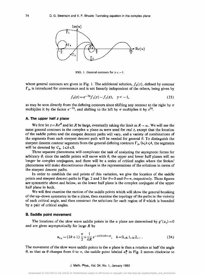
FIG. 1. General contours for y < - 1.
whose general contours are given in Fig. 1. The additional solution, fo(z), defined by contour ro, is introduced for convenience and is not linearly independent of the others, being given by
f&l =e-29f3(z) -f2(z), y< - 1, (23)
as may be seen directly from the defining contours since shifting any contour to the right by r multiplies it by the factor em2$, and shifting to the left by r multiplies it by 2?.
A. The upper half z plane
We first let z= Reie and let R be large, eventually taking the limit as R -, 03. We will use the same general contours in the complex u plane as were used for real z, except that the location of the saddle points and the steepest descent paths will vary, and a variety of combinations of the segments from each steepest descent path will be needed for general 8. To distinguish the steepest descent contour segments from the general defining contours rk, O<k<4, the segments will be denoted by C,, 1 <k<8.
Three separate phenomena will complicate the task of analyzing the asymptotic forms for arbitrary 8, since the saddle points will move with 8, the upper and lower half planes will no longer be complex conjugates, and there will be a series of critical angles where the Stokes’ phenomena will make discontinuous changes in the representations of the solutions in terms of the steepest descent paths.
In order to establish the end points of this variation, we give the location of the saddle points and steepest descent paths in Figs. 2 and 3 for 8=0 and e=r, respectively. These figures are symmetric above and below, so the lower half plane is the complex conjugate of the upper half plane in both.
We will first examine the motion of the saddle points which will show the general breaking of the up-down symmetry in the u plane, then examine the topology of the paths in the vicinity of each critical angle, and then construct the solutions for each region of 8 which is bounded by a pair of critical angles.
B. Saddle point movement
The locations of the slow wave saddle points in the 11 plane are determined by g’( us) =0 and are given asymptotically for large R by
11 k=0,*1,*2 ,... . (24)
The movement of the slow wave saddle points in the II plane is thus a rotation at half the angle 8, so that as 8 changes from 0 to n-, the saddle point labeled UT in Fig. 2 moves clockwise to
J. Math. Phys., Vol. 34, No. 1, January 1993
Downloaded 21 Feb 2013 to 131.104.62.10. Redistribution subject to AIP license or copyright; see http://jmp.aip.org/about/rights_and_permissions
D. G. Swanson and V. F. Shvets: Tunneling equation in the complex plane 75
FIG. 2. Contours for 0=0 (y< -1).
the real axis to the position of U, in Fig. 3. Similarly, the saddle point labeled ai in Fig. 2 rotates clockwise to the position of the saddle point labeled a2 in Fig. 3.
The fast wave saddle points primarily translate to the right or left in the u plane with little change in the imaginary part, so that af is given asymptotically by
i uf*= *-ln 2 (25)
The upper fast wave saddle point labeled u2 in Fig. 2 moves to the left to the position labeled u3 in Fig. 3, while the lower fast wave saddle point labeled uz in Fig. 2 moves to the right until it is v to the right of UT in Fig. 3 as 8 changes from 0 to r.
Im( u) +
FIG. 3. Contours for @=P (y< -1).
J. Math. Phys., Vol. 34, No. 1, January 1993
Downloaded 21 Feb 2013 to 131.104.62.10. Redistribution subject to AIP license or copyright; see http://jmp.aip.org/about/rights_and_permissions
76 D. G. Swanson and V. F. Shvets: Tunneling equation in the complex plane
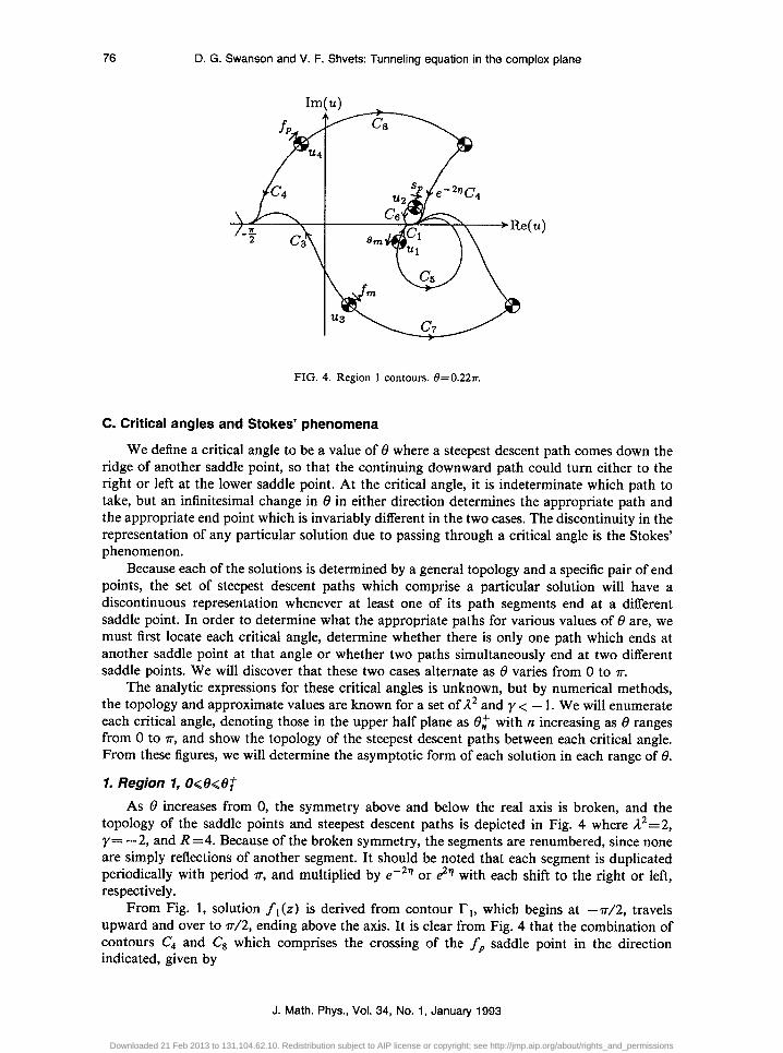
FIG. 4. Region 1 contours. 0=0.22~.
C. Critical angles and Stokes’ phenomena
We define a critical angle to be a value of 8 where a steepest descent path comes down the ridge of another saddle point, so that the continuing downward path could turn either to the right or left at the lower saddle point. At the critical angle, it is indeterminate which path to take, but an infinitesimal change in 8 in either direction determines the appropriate path and the appropriate end point which is invariably different in the two cases. The discontinuity in the representation of any particular solution due to passing through a critical angle is the Stokes’ phenomenon.
Because each of the solutions is determined by a general topology and a specific pair of end points, the set of steepest descent paths which comprise a particular solution will have a discontinuous representation whenever at least one of its path segments end at a different saddle point. In order to determine what the appropriate paths for various values of 8 are, we must first locate each critical angle, determine whether there is only one path which ends at another saddle point at that angle or whether two paths simultaneously end at two different saddle points. We will discover that these two cases alternate as 8 varies from 0 to P.
The analytic expressions for these critical angles is unknown, but by numerical methods, the topology and approximate values are known for a set of A2 and y < - 1. We will enumerate each critical angle, denoting those in the upper half plane as 0: with n increasing as 8 ranges from 0 to r, and show the topology of the steepest descent paths between each critical angle. From these figures, we will determine the asymptotic form of each solution in each range of 8.
1. Region 7, o<e<e: As 8 increases from 0, the symmetry above and below the real axis is broken, and the
topology of the saddle points and steepest descent paths is depicted in Fig. 4 where A2=2, y= -2, and R =4. Because of the broken symmetry, the segments are renumbered, since none are simply reflections of another segment. It should be noted that each segment is duplicated periodically with period rr, and multiplied by e-29 or e2v with each shift to the right or left, respectively.
From Fig. 1, solution f,(z) is derived from contour l?,, which begins at -r/2, travels upward and over to rr/2, ending above the axis. It is clear from Fig. 4 that the combination of contours C4 and Cs which comprises the crossing of the fp saddle point in the direction indicated, given by
J. Math. Phys., Vol. 34, No. 1, January 1993
Downloaded 21 Feb 2013 to 131.104.62.10. Redistribution subject to AIP license or copyright; see http://jmp.aip.org/about/rights_and_permissions
D. G. Swanson and V. F. Shvets: Tunneling equation in the complex plane 77
will provide the connection between - rr/2 and ?r/2, but it ends at the axis instead of above the axis. The connection between the ending points is provided by crossing the sP saddle point at each end, so that we may write, beginning at -r/2,
f, =e2qsp+ fp-sp=e2%sp+ fp .
The simplest solution in this range is f4(z), since it is simply the left-shifted saddle point sP which must be crossed, so
f 4 = - e2”sp .
In constructing f 3 (z), we leave the end point at - ?r/2, crossing the left-shifted s, saddle point in the positive direction, traverse the f,, saddle point, and then cross the sP saddle point to reach the end point at rr/2 from above. We hence have
f3=ezqs,+ fp--sp.
For the remaining solutions, we must cross the f,,, saddle point, which represents the contour segments
f,= -C3+C7+e-2~C3=C7--EC3.
We construct fo(z) by starting from the end point at 7r/2, crossing the s, saddle point, then over the f m saddle point followed by the fp saddle point, returning to IT/~ after crossing the sP saddle point so that we end above the axis. Thus
fo=sm-fm+fp-sp *
Finally, we construct the f2(z) solution by starting at rr/2 and crossing the s,, saddle point, then fp and f m to return to r/2 on the real axis, then crossing the right-shifted f,, saddle point to reach 3?r/2, and finally crossing the right-shifted sP to end above the axis. This path yields
f2=sp-fp+ fm+e-2’7f,-e-2qsp=4sp-fp) +f, .
The first critical angle in the upper half plane, denoted @‘, occurs when the steepest descent path e -2’K’, in Fig. 4 from the right-shifted saddle point uq+ v ends on the saddle point u2. Simultaneously, the path C, from saddle point u1 ends at the saddle point u3. Hence for 6: < 8 < @, the path ee2%‘, ends on the axis at rr/2 from above the axis, following C, to its end point. In the same range, path Cs will end on the axis at -7-r/2, following paths C3 and C, to its end point. For A2=2, y= -2, and R=4, 0fcr0.265n while for R = 10, 0f -0.290~.
2. Region 2, e;<e<e$ In this region, where the contour segments are illustrated in Fig. 5, solution f,(z) is
especially simple, since now we have
Solution f4(z) is unchanged, and fo(z) is now given by first crossing s,, then the left-shifted sP and finally fp This solution is given by
fo=s,-e2qsp+ fp .
J. Math. Phys., Vol. 34, No. 1, January 1993
Downloaded 21 Feb 2013 to 131.104.62.10. Redistribution subject to AIP license or copyright; see http://jmp.aip.org/about/rights_and_permissions
78 D. G. Swanson and V. F. Shvets: Tunneling equation in the complex plane
FIG. 5. Region 2 contours. 6=0.28n
Solution f3(z) is more complicated, crossing first the left-shifted s, saddle point ending at --r/2, then crossing the left-shifted f,,, to return to -rr/2 on axis, then crossing the left- shifted sP and the fp saddle points. This gives
f3=e2qs,+e2~fm-e2qsp+ fp=e2q(s,+ f,-s,) + fp .
Finally, for f 2(z), we cross the s, and f m saddle points to get to 7r/2 on the axis, then cross the sP and right-shifted fp to the end. This yields
The next critical angle, denoted @, occurs when the steepest descent path C, from the saddle point U, in Fig. 5 ends on the shifted saddle point u2 - r. Hence for 08 < 8 < @, the path C, ends at - 7~/2 from above the axis, following C, to its end point. For R =4, we find that 02 -0.29%, while for R= 10, 0: -0.341~.
3. Region 3, e,+ceGe; By comparing Fig. 5 with Fig. 6 for region 3, it is apparent that solutions f,(z) and f4(z)
are unchanged from region 2. Solution fo(z) is somewhat simpler, being given by
Solution f2 is similar to the previous case, and is given by
f2=de2qsp-fp) +f, .
We may find f3 either from following the contours or by using Eq. (23) to obtain
f3=e2q(s,+fm+e2qqJ +fp.
The third critical angle in the upper half plane, denoted et, occurs when the steepest descent path C, from the saddle point u1 in Fig. 6 ends on the saddle point ZQ. Simultaneously, the path C, from saddle point u3 ends at the left-shifted saddle point u2-7r. Hence for 0; < 8 < 0:, the path C, ends on the axis at r/2 from above the axis, following C, to its end point.
J. Math. Phys., Vol. 34, No. 1, January 1993
Downloaded 21 Feb 2013 to 131.104.62.10. Redistribution subject to AIP license or copyright; see http://jmp.aip.org/about/rights_and_permissions
D. G. Swanson and V. F. Shvets: Tunneling equation in the complex plane 79
FIG. 6. Region 3 contours. 8=0.35~.
In the same range, path C3 will end on the axis at -rr/2 from above, following path C, to its end point. For R =4, we find that 0; ,0.3107r, while for R = 10, 05 -0.3415~ which means that asymptotically, 0,’ -0; so that these two critical angles have merged.
4. Region 4, e;cecef Again comparing Fig. 6 with Fig. 7, it is clear that in this range, ft and f4 remain
unchanged, while f. simplifies so that
The other two solutions are
e -2”c3
FIG. 7. Region 4 contours. 0=0.347r.
J. Math. Phys., Vol. 34, No. 1, January 1993 Downloaded 21 Feb 2013 to 131.104.62.10. Redistribution subject to AIP license or copyright; see http://jmp.aip.org/about/rights_and_permissions
80 D. G. Swanson and V. F. Shvets: Tunneling equation in the complex plane
Im(u>
Re(u)
FIG. 8. Region 5 contours. 0=0.6a.
and
The next critical angle in the upper half plane, denoted e$, occurs when the steepest descent path C3 from the saddle point a3 in Fig. 7 ends on the saddle point U+ Hence for 04’ < 8 < et, the path C3 ends at rr/2 from above the axis, following C, to its end point. For R =4, we find that 0: ,0.3557r, while for R = 10, 0,$ -0.4351r.
5. Region 5, et6e6e; Comparing Figs. 7 and 8, we find this time that in region 5, fo, f ,, and f4 remain the same,
while f2 simplifies to
f2=fin *
We also find f 3 from either the contours or Eq. (23) to be
The last critical angle in the upper half plane, denoted 0:) occurs when the steepest descent path labeled e2’7C, from the left-shifted saddle point u~--‘TT in Fig. 8 ends on the saddle point q. Simultaneously, the path C3 from saddle point a3 ends at the saddle point ui. Hence for @ < 8 < & the path C3 from u3 ends on the axis at 7r/2 from below the axis as shown in Fig. 9. In the same range, the path labeled e2V, ends on the axis at 7r/2 from above, following path C, to its end point as in Fig. 9. For R=4, we find that (3: -0.846a, while for R= 10, (3; -0.918~.
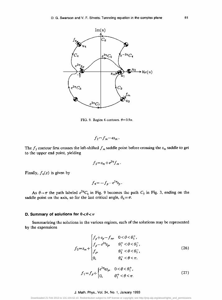
6. Region 6, e5f686r Finally, referring to Fig. 9, we find in region 5 that f. and f 1 are again unchanged, but the
others all change. The f2(z) contour first crosses the s,,, saddle point before crossing the f,,, and finally the right-shifted s, saddle points. This leads to
J. Math. Phys., Vol. 34, No. 1, January 1993
Downloaded 21 Feb 2013 to 131.104.62.10. Redistribution subject to AIP license or copyright; see http://jmp.aip.org/about/rights_and_permissions
D. G. Swanson and V. F. Shvets: Tunneling equation in the complex plane 81
,Re(u)
FIG. 9. Region 6 contours. B=0.9a.
The f 3 contour first crosses the left-shifted f m saddle point before crossing the s, saddle to get to the upper end point, yielding
Finally, f 4(z) is given by
f4= - fp-e2qsp.
As 8-n the path labeled e2qC, in Fig. 9 becomes the path C, in Fig. 3, ending on the saddle point on the axis, so for the last critical angle, 06=rr.
D. Summary of solutions for O<B<v
Summarizing the solutions in the various regions, each of the solutions may be represented by the expressions
fo=snl+
fp+sp-fm, o<eW,
fp-e2qspl e,+ <e<e,+, fP’
e,+ <e<e,+, 0, 0; <ecrr.
1
e2qes f1=fp+ o
a o<e<e,+, 9 e; <e0-.
(26)
(27)
J. Math. Phys., Vol. 34, No. 1, January 1993 Downloaded 21 Feb 2013 to 131.104.62.10. Redistribution subject to AIP license or copyright; see http://jmp.aip.org/about/rights_and_permissions
82 D. G. Swanson and V. F. Shvets: Tunneling equation in the complex plane
In order to determine whether one can close the contours in the upper half plane, we now need the asymptotic forms of the saddle point contributions since each of the solutions is written in terms of these.
The fast wave term fp-e ’ is exponentially small for all 0 < 8 < rr, so this term will cause no difficulty in closing above, but is exponentially large if one were to close below.
The fast wave term f ,-e-” is exponentially large for all 0 < 0< rr, so this term will generally prevent one from closing above, but is exponentially small if one closes below. A product of fp and f, may be closed either above or below if multiplied by another convergent factor.
The exponential factor in the slow wave term s, is given by
so that the real part of the exponent is positive for all 0 < 8 < 2~/3 and negative for 2n-/3 < 8 <P. This means that s, is exponentially large for all 0<02, changes character in the range 02 < 8 < @, and is exponentially small for 8 > 0:.
The exponential factor in the slow wave term sp is given by
2i . . 5~jv2=i!~~3~2 exp y+?f
( )
so that the real part of the exponent is negative for all 0 < 8 < 2rr/3 and positive for 2?r/3 < 8 < 7~. This means that sp is exponentially small for all 0<02, changes character in the range 02 < 8 < f3:, and is exponentially large for 8 > 0:. 1. Solution f,
Since fp is exponentially small for all 8 in the upper half plane, f 1 (z) is well behaved, since the slow wave term, which is pertinent only for 0 < 8 <et, is also well behaved in that range
J. Math. Phys., Vol. 34, No. 1, January 1993
Downloaded 21 Feb 2013 to 131.104.62.10. Redistribution subject to AIP license or copyright; see http://jmp.aip.org/about/rights_and_permissions
D. G. Swanson and V. F. Shvets: Tunneling equation in the complex plane 83
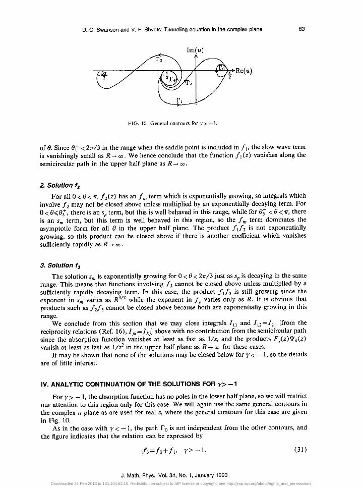
FIG. 10. General contours for y> - 1.
of 8. Since 6: < 2?r/3 in the range when the saddle point is included in f ,, the slow wave term is vanishingly small as R -+ CO. We hence conclude that the function f r (z) vanishes along the semicircular path in the upper half plane as R + CO.
2. Solution f,
For all 0 < 8 < r, f2(z) has an f, term which is exponentially growing, so integrals which involve f2 may not be closed above unless multiplied by an exponentially decaying term. For 0 < &@, there is an sp term, but this is well behaved in this range, while for 0: < 8 < r, there is an s, term, but this term is well behaved in this region, so the f, term dominates the asymptotic form for all 8 in the upper half plane. The product f, f 2 is not exponentially growing, so this product can be closed above if there is another coefficient which vanishes sufficiently rapidly as R -+ CO.
3. Solution fs
The solution s, is exponentially growing for 0 < 8 < 2?r/3 just as sp is decaying in the same range. This means that functions involving f3 cannot be closed above unless multiplied by a sufficiently rapidly decaying term. In this case, the product f, f3 is still growing since the exponent in s, varies as R312 while the exponent in fp varies only as R. It is obvious that products such as fif3 cannot be closed above because both are exponentially growing in this range.
We conclude from this section that we may close integrals I,, and Zt2=Z2i [from the reciprocity relations (Ref. 16), Zjk=Zkj] above with no contribution from the semicircular path since the absorption function vanishes at least as fast as l/z, and the products F&z)Yk(z) vanish at least as fast as l/g in the upper half plane as R -+ CO for these cases.
It may be shown that none of the solutions may be closed below for y < - 1, so the details are of little interest.
IV. ANALYTIC CONTINUATION OF THE SOLUTIONS FOR y> -1
For y> - 1, the absorption function has no poles in the lower half plane, so we will restrict our attention to this region only for this case. We will again use the same general contours in the complex u plane as are used for real z, where the general contours for this case are given in Fig. 10.
As in the case with y< - 1, the path IO is not independent from the other contours, and the figure indicates that the relation can be expressed by
f3=fo+f 1, Y’ - 1. (31)
J. Math. Phys., Vol. 34, No. 1, January 1993 Downloaded 21 Feb 2013 to 131.104.62.10. Redistribution subject to AIP license or copyright; see http://jmp.aip.org/about/rights_and_permissions
84 D. G. Swanson and V. F. Shvets: Tunneling equation in the complex plane
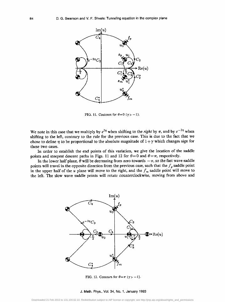
FIG. 11. Contours for 0=0 (y> - 1)
We note in this case that we multiply by e2q when shifting to the right by z-, and by e-2q when shifting to the left, contrary to the rule for the previous case. This is due to the fact that we chose to define 7 to be proportional to the absolute magnitude of 1 + y which changes sign for these two cases.
In order to establish the end points of this variation, we give the location of the saddle points and steepest descent paths in Figs. 11 and 12 for 6=0 and 8=rr, respectively.
In the lower half plane, 8 will be decreasing from zero towards -rr, so the fast wave saddle points will travel in the opposite direction from the previous case, such that the fP saddle point in the upper half of the u plane will move to the right, and the f,,, saddle point will move to the left. The slow wave saddle points will rotate counterclockwise, moving from above and
FIG. 12. Contours for 8=n (y> - 1).
J. Math. Phys., Vol. 34, No. 1, January 1993
Downloaded 21 Feb 2013 to 131.104.62.10. Redistribution subject to AIP license or copyright; see http://jmp.aip.org/about/rights_and_permissions
D. G. Swanson and V. F. Shvets: Tunneling equation in the complex plane 85
below the real axis to symmetric positions on either side of the end points on the real axis as 0 decreases from zero towards -v.
A. Critical angles and Stokes’ phenomena
Each critical angle in this range will be denoted 19;, with 1 <n<6, where again @ = e6= 7~.
7. Critical angle t9;
The first critical angle in the lower half plane, denoted f3,, occurs when the steepest descent path C, from the saddle point ui in Fig. 11 ends on the saddle point u2. Simultaneously, the path Q from saddle point u: ends at saddle point UT. Hence for 0, < 8 < 0;, the path C’s ends on the axis at -r/2, following the shifted C2 to its end point. In the same range, path q will end below the axis at 7r/2, following path q to its end point. For A2=2 and y= -0.5 and R =4, we find that (3, 2? -0.2021r, while for R = 10, 0, = -0.271~.
2. Critical angle e;
The next critical angle in the lower half plane, denoted &, occurs when the steepest descent path C, from the saddle point u1 in Fig. 11 ends on the saddle point UT - 7r (the left-shifted UT). Hence for (3, < 8 < tI,, the path C, ends below the axis at -n/2, following the left-shifted c to its end point. For R=4, we find that 0F 2: -0.301~, while for R = 10, e; 2! -0.354~.
3. Critical angle e,-
The next critical angle, denoted f3,, occurs when the steepest descent path C2 from the saddle point u2 in Fig. 11 ends on the saddle point U, . * Simultaneously, the path Cs from saddle point u1 ends at the left-shifted saddle point U: - r. Hence for f3,- < 8 < f3,, the path C, ends below the axis at 7r/2, following the path e to its end point. In the same range, path C2 will end at the same point, following path q to its end point. For R=4, we find that 0, E -0.353~, while for R= 10, f3, N -0.3547r so that 0, merges with 0, in the asymptotic limit.
4. Critical angle e,
The next critical angle in the lower half plane, denoted f3;, occurs when the steepest descent path labeled ee2’K’, from left-shifted saddle point u2- v in Fig. 11 ends on the saddle point ~1. Hence for 0, < 8 < 6,, the path e -2’rC2 ends below the axis at ?r/2, following the path q to its end point. For R =4, we find that @T E -0.498~, while for R = 10, f3r = -0.502~.
5. Critical angle e,
The next critical angle, denoted &, occurs when the left-shifted path ee2’C2 from the saddle point u2 - r in Fig. 11 ends on the saddle point u i. At this same angle, the saddle point u2 - 7r is nearly on the imaginary axis, having moved to the right by 0.45n. Also, the saddle point U, is almost rotated to the axis, lying to the left of rr/2. Simultaneously, the path c;” from saddle point UT ends at the saddle point UT, whose real part is now almost at r. An alternate description of this transition is that path Cs in Fig. 12 ends at saddle point u1 (slightly above the axis) at the same time path Cs ends at ~7 in Fig. 12. Hence for -V < 8 < 0,, using this latter figure, the path C, ends above the axis at 7r/2, following the path C, to its end point. In the same range, path C, will end below the axis at 7r/2 following q to its end point. For R =4, we find that 0, = -0.896rr, while for R = 10, 0, P -0.933~.
J. Math. Phys., Vol. 34, No. 1, January 1993 Downloaded 21 Feb 2013 to 131.104.62.10. Redistribution subject to AIP license or copyright; see http://jmp.aip.org/about/rights_and_permissions
88 D. G. Swanson and V. F. Shvets: Tunneling equation in the complex plane
6. Critical angle e6
The final critical angle, denoted &,, occurs at 8= -v, so is the final transition for either the upper or lower half plane. The critical situation is illustrated in Fig. 12 where path C’s ends on saddle point u,. For 8 in the lower half plane, path C, follows path q to its end point in the lower half plane, while in the upper half plane, C, will follow C, to its end in the upper half plane.
6. Summary of solutions in the lower half plane
Following the procedures from the case with y< - 1 but using Fig. 10 for the general contours, and Fig. 11 for the location and direction of the saddle points, fp f,, sp s,, we find the solutions in the various regions are given by the following expressions:
, sm-fm+fp 0; <e-a
e-2Ts,-fm, e, <e<e;,
f”=sp+ -f,, e,<e<e- 29 &a -6e<er;
f = fm+Es,,
1
e;<e<o,
l fm --6e<ee,;
I eem2%,, e, <e<o,
(33)
f2= -em2’lfp+
i
0, e,- <e<e;, Ef
m, e; <e<e,-,
Ef m + =p, --n<e<e;;
‘fp+e-2qs,, e; <e<o,
em2b m, e; <e<e;,
f3=sp+' 0, e, <e<e;,
.f ??I, -he<e;;
f4(z) =em29,+ I 0, e;<e<o, f RI, --ce8e8,. (36)
C. Asymptotic behavior as R+ CO
From the asymptotic forms of the saddle point contributions in Sec. III E, we can use the general expressions in each region to determine the behavior of each solution as R -+ CO over the lower half plane.
1. Solution f,
Since f _ is exponentially small for all 8 in the lower half plane, fl (z) is well behaved, since the slow wave term, which is pertinent only for f3, < 8 < 0, is also well behaved in that range 0f 8.
Since 0, > - 21r/3, in the range when the saddle point is included in f ,, the slow wave term is vanishingly small as R + 03. We hence conclude that the function f i (z) vanishes along the semicircular path in the lower half plane as R --+ CO.
J. Math. Phys., Vol. 34, No. 1, January 1993
Downloaded 21 Feb 2013 to 131.104.62.10. Redistribution subject to AIP license or copyright; see http://jmp.aip.org/about/rights_and_permissions
D. G. Swanson and V. F. Shvets: Tunneling equation in the complex plane 87
2. Solution fz For all -P < 8 < 0, f2(z) has an f + term which is exponentially growing, so integrals
which involve f 2 may not be closed below unless multiplied by an exponentially decaying term. For 0; < 8(0, there is an s- term, but this is well behaved in this range, while for --rr < 8 4, there is an s+ term, but this term is well behaved in this region, so the f + term dominates the asymptotic form for all 0 in the lower half plane. The product f, f2 is not exponentially growing, so this product can be closed below if there is a coefficient which vanishes sufficiently rapidly as R + CO.
3. Solution f3 The solution s+ is exponentially growing for - 2~/3 < 8 < 0 just as s- is decaying in the
same range. This means that functions involving f3 cannot be closed below unless multiplied by a sufficiently rapidly decaying term. In this case, the product f ,f3 is still growing since the exponent in s+ varies as R3’2 while the exponent in f _ varies only as R. It is obvious that products such as fif3 cannot be closed below because both are exponentially growing in this range.
V. THE $ INTEGRALS
A. The case y> - 1
Since there are no poles either in Fj(z), h(z), or Y,(z) in the lower half z plane, whose products form the integrand for the Ij~, it follows that any of the contour integrals that may be closed in the lower half z plane without any contribution from the semicircular path as R tends to infinity must vanish. In Sec. IV C, we concluded that the integrals I,, and 112=12, could be closed below, so it follows that
(37)
from which it follows from Table I that
R1=O, (38)
T, = T2=e-v,
for any absorption term that has no poles in the lower half plane. These results coincide precisely with the conjectures of Eqs. (13) and (14) based on numerical evaluations. Since it has now been proved that the integrals of Eq. (37) vanish identically, evaluating them numer- ically may provide a basis for error estimates with any numerical scheme.
B. The case y< - 1
All the arguments above for the case with y> - 1 follow for this case if everywhere we close above instead of below and use only absorption functions that have no poles in the upper half plane. In fact, the requirement that the h(z) have no poles below for y> - 1 and no poles above for y < - 1 is equivalent to saying that we require h(z) to be an absorption function, since if h(z) does not satisfy this requirement, it contains a source as well as a sink.
VI. CONCLUSIONS
The proof that the reflection coefficient (from the side which sees the resonance before the cutoff) vanishes is not so surprising, since reflection is normally associated with a cutoff, and it is hard to see how the addition of absorption would induce reflection. The other conclusion, however, that the transmission coefficient is totally independent of absorption, and depends
J. Math. Phys., Vol. 34, No. 1, January 1993 Downloaded 21 Feb 2013 to 131.104.62.10. Redistribution subject to AIP license or copyright; see http://jmp.aip.org/about/rights_and_permissions
88 D. G. Swanson and V. F. Shvets: Tunneling equation in the complex plane
only on the asymptotic parameters A and y is surprising. As noted previously, in weakly inhomogeneous layers, the WKB approximation suggests that the transmission coefficient may be obtained by integrating the imaginary part of k(s) across the absorbing layer as in Eq. (4), where it is presumed that the imaginary part is due to absorption. The fact that the transmis- sion coefficient depends only on tunneling and not on absorption is thus contrary to conven- tional wisdom and forces the redefinition of the concept of opacity. The analytical results obtained in this paper have been observed in previous numerical calculations, but this proof indicates its generality in a way calculations can never do. When this result is coupled with the redefinition of opacity relevant to mode conversion layers through the Generalized Kirchhoff s Law,’ the interpretation of emission, absorption, transmission, reflection, and conversion have all undergone a fundamental change, and we must leave the more simplistic arguments behind in analyzing experiments and in our thinking. While the conventional calculation of opacity appears in standard texts,lO*‘l its application to mode conversion layers must be revised, since although the plasma parameters may vary slowly, the refractive index does not, experiencing both a resonance and cutoff, so the application of the standard theory to such cases is invalid.
We found exact expressions for only three of the integrals and their corresponding scat- tering parameters. Another result from numerical studies suggests that R2 = -Ee- * for the nonrelativistic absorption function of Eq. (20) where K is proportional to the parallel wave number and controls the strength of absorption.3t4 Finding an exact expression for this as well as any of the other scattering parameters is still an open unsolved problem.
ACKNOWLEDGMENT
This work was supported by the U.S. Department of Energy under Contract No. DE- FG05-85ER53206-91.
‘N. S. Erokhin and S. S. Moiseev, Reviews of Plasma Physics (Consultants Bureau, New York, 1979), Vol. 7, p. 181. ‘T. H. Stix and D. G. Swanson, Basic Plasma Physics, edited by A. A. Galeev and R. N. Sudan (North-Holland,
Amsterdam, 1983), Vol. 1, p. 335. ‘D. G. Swanson, Phys. Fluids 28, 2645 (1985). ‘D. G. Swanson, Plasma Waves (Academic, Boston, 1989). ‘D. G. Swanson and V. F. Shvets, Phys. Rev. L&t. 68, 3036 ( 1992). 6Y. C. Ngan and D. G. Swanson, Phys. Fluids 20, 1920 (1977). 7T. M. Antonsen and W. M. Manheimer, Phys. Fluids 21, 2295 ( 1978). *D. W. Faulconer, Phys. Lett. A 75, 355 (1980). ‘D. G. Swanson, Phys. Fluids 21, 926 (1978).
“G. Bekefi, Radiation Processes in Plasmas (Wiley, New York, 1966). ” D. B. Melrose and R. C. McPhedran, Electromagnetic Processes in Dispersive Media (Cambridge University, Cam-
bridge, 1991). “M Abramowitz and I. Stegun, Handbook of Mathematical Functions (National Bureau of Standards, Washington,
DC, 1964). “B. D. Fried and S. D. Conte, The Plasma Dispersion Function (Academic, New York, 1961). “I. P. Shkarofsky, Phys. Fluids 9, 561 (1966). “P. A. Robinson, J. Math. Phys. 30, 2484 (1989). ‘%uwon Cho and D. G. Swanson, Phys. Fluids B 2, 2704 (1990).
J. Math. Phys., Vol. 34, No. 1, January 1993
Downloaded 21 Feb 2013 to 131.104.62.10. Redistribution subject to AIP license or copyright; see http://jmp.aip.org/about/rights_and_permissions