PREPARATION ................................................... 3Special Service Tool .................................................3Commercial Service Tool ..........................................3
Observe the following precautions when disassembling and servicing drive shaft.• Perform work in a location which is as dust-free as possible.• Before disassembling and servicing, clean the outside of parts.• Prevention of the entry of foreign objects must be taken into account during disassembly of the service loca-
tion.• Disassembled parts must be carefully reassembled in the correct order. If work is interrupted, a clean cover
must be placed over parts.• Paper shop cloths must be used. Fabric shop cloths must not be used because of the danger of lint adhering
to parts.• Disassembled parts (except for rubber parts) should be cleaned with kerosene which shall be removed by
blowing with air or wiping with paper shop cloths.
RAX-2
PREPARATION
C
E
F
G
H
I
J
K
L
M
A
B
AX
N
O
P
< PREPARATION >
R
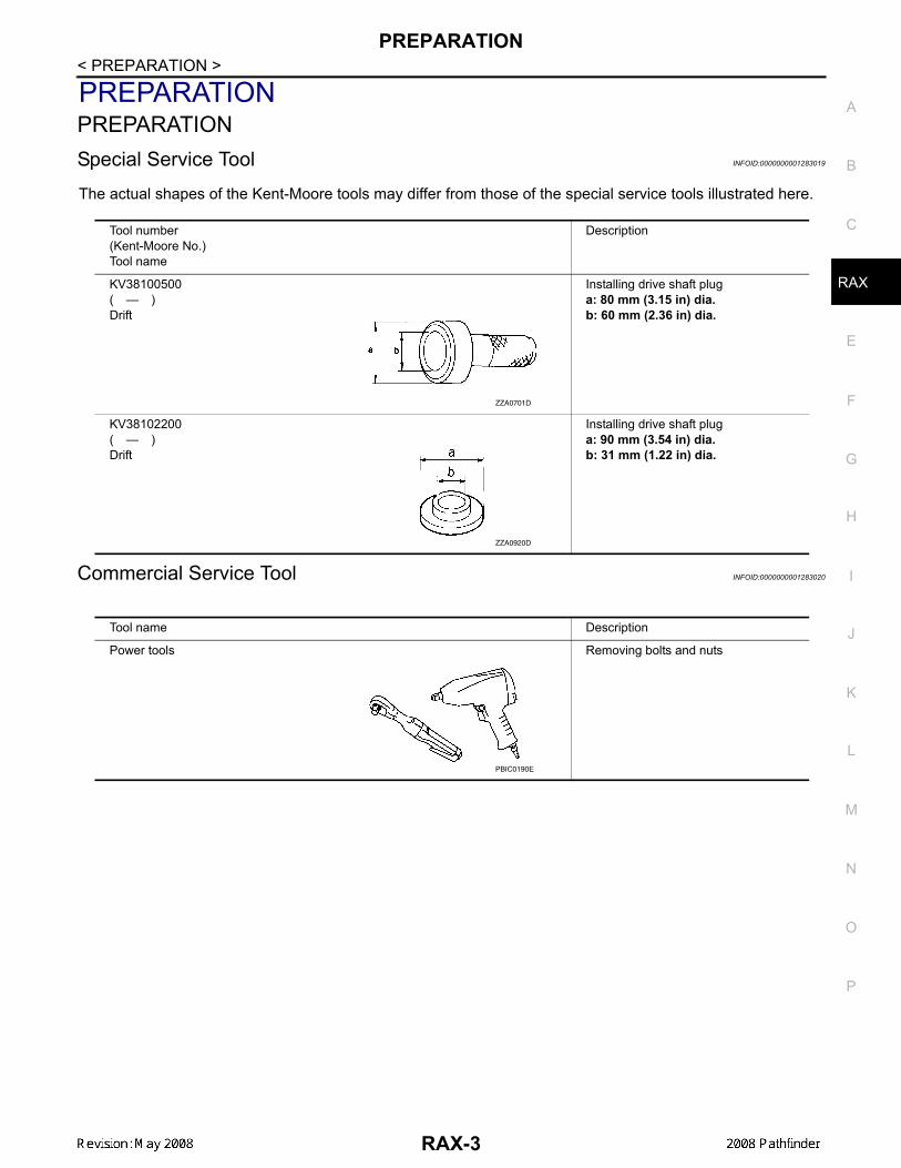
PREPARATIONPREPARATIONSpecial Service Tool INFOID:0000000001283019
The actual shapes of the Kent-Moore tools may differ from those of the special service tools illustrated here.
Commercial Service Tool INFOID:0000000001283020
Tool number(Kent-Moore No.)Tool name
Description
KV38100500( — )Drift
Installing drive shaft pluga: 80 mm (3.15 in) dia.b: 60 mm (2.36 in) dia.
KV38102200( — )Drift
Installing drive shaft pluga: 90 mm (3.54 in) dia.b: 31 mm (1.22 in) dia.
ZZA0701D
ZZA0920D
Tool name Description
Power tools Removing bolts and nuts
PBIC0190E
RAX-3
NOISE, VIBRATION, AND HARSHNESS (NVH) TROUBLESHOOTING
Ref
ST-
9, "N
VH T
roub
lesh
ootin
g C
hart"
Pos
STE
ER
ING
Sym
×
×
×
×
×
×
< SYMPTOM DIAGNOSIS >
SYMPTOM DIAGNOSISNOISE, VIBRATION, AND HARSHNESS (NVH) TROUBLESHOOTINGNVH Troubleshooting Chart INFOID:0000000001283021
Use chart below to help you find the cause of the symptom. If necessary, repair or replace these parts.
×: Applicable
erence page —
RA
X-9
—
RA
X-8
—
DLN
-402
, "N
VH T
roub
lesh
ootin
g C
hart"
(R20
0)D
LN-4
39, "
NVH
Tro
uble
shoo
ting
Cha
rt" (R
230)
FAX
-4, "
NV
H T
roub
lesh
ootin
g C
hart"
FSU
-4, "
NVH
Tro
uble
shoo
ting
Cha
rt"
RS
U-4
, "N
VH
Tro
uble
shoo
ting
Cha
rt"
WT-
44, "
NV
H T
roub
lesh
ootin
g C
hart"
WT-
44, "
NV
H T
roub
lesh
ootin
g C
hart"
DLN
-306
, "N
VH
Tro
uble
shoo
ting
Cha
rt" (2
F131
0)D
LN-3
14, "
NV
H T
roub
lesh
ootin
g C
hart"
(2S
1330
)D
LN-3
23, "
NV
H T
roub
lesh
ootin
g C
hart"
(2S
1350
)
BR
-5, "
NV
H T
roub
lesh
ootin
g C
hart"
sible cause and SUSPECTED PARTS
Exc
essi
ve jo
int a
ngle
Join
t slid
ing
resi
stan
ce
Imba
lanc
e
Impr
oper
inst
alla
tion,
loos
enes
s
Par
ts in
terfe
renc
e
RE
AR
FIN
AL
DR
IVE
FRO
NT
AX
LE
FRO
NT
SU
SP
EN
SIO
N
RE
AR
SU
SP
EN
SIO
N
TIR
ES
RO
AD
WH
EE
L
PR
OP
ELL
ER
SH
AFT
BR
AK
ES
ptom
Noise × × × × × × × × × × ×
Shake × × × × × × × × × ×
Vibration × × × × × × × ×
Shimmy × × × × × × ×
Shudder × × × × × ×
Poor quality ride or handling × × × × × × ×
RAX-4
WHEEL HUB
C
E
F
G
H
I
J
K
L
M
A
B
AX
N
O
P
< ON-VEHICLE MAINTENANCE >
R
ON-VEHICLE MAINTENANCEWHEEL HUBOn-Vehicle Inspection and Service INFOID:0000000001283022
Inspect the components for any looseness or backlash. Inspect each component for any excessive wear ordamage. Replace any components as necessary.
WHEEL BEARING INSPECTION• Move the rear wheel hub and bearing assembly in the axial direction by hand to check the axial end play.
Check that the axial end play is with specification. Replace the rear wheel hub and bearing assembly asnecessary.
• Rotate the rear wheel hub and bearing assembly to check that there are no unusual noises or other abnor-mal conditions. Replace the rear wheel hub and bearing assembly as necessary.
REMOVAL AND INSTALLATIONWHEEL HUBRemoval and Installation INFOID:0000000001283024
REMOVAL1. Remove the wheel and tire assembly using power tool.2. Remove the rear brake caliper, without disconnecting the hydraulic hose, using power tool. Reposition the
rear brake caliper aside using suitable wire. Refer to BR-29, "Removal and Installation of Brake Caliperand Disc Rotor".NOTE:Do not depress the brake pedal while the brake caliper is removed.
3. Remove the rear disc rotor.4. Remove the cotter pin, then remove the rear drive shaft nut using power tool.
• Discard the cotter pin, use a new one for installation.5. Remove the rear drive shaft. Refer to RAX-9, "Removal and Installation".
6. Remove the four rear wheel hub and bearing assembly bolts using power tool.• Discard the four rear wheel hub and bearing assembly bolts, use new ones for installation.
7. Remove the rear wheel hub and bearing assembly.
INSTALLATIONInstallation is in the reverse order of removal.• Use a new cotter pin for installation.• Use new rear wheel hub and bearing assembly bolts for installation.
RAX-8
REAR DRIVE SHAFT
C
E
F
G
H
I
J
K
L
M
A
B
AX
N
O
P
< REMOVAL AND INSTALLATION >
R
REAR DRIVE SHAFTRemoval and Installation INFOID:0000000001283026
REMOVAL1. Remove the wheel and tire assembly using power tool.2. Remove the cotter pin and discard, then remove the lock nut from the drive shaft.
• Do not reuse the cotter pin, discard after removal and use a new cotter pin for installation.3. Remove the six rear drive shaft bolts from the rear final drive assembly flange using power tool.
• Do not reuse the rear drive shaft bolts, discard after removal and use new bolts for installation.4. Separate the rear drive shaft from the rear wheel hub and bearing assembly by lightly tapping the end of
the rear drive shaft with a suitable hammer and wood block. If it is difficult to separate, use a suitablepuller.
5. Remove the rear drive shaft.CAUTION:• When removing the rear drive shaft, do not bend at an excessive angle to the rear drive shaft
joint.• Do not excessively extend the slide joint.
INSPECTION AFTER REMOVAL• Move the joint up and down, left and right, and in the axial direc-
tion. Check for any rough movement or significant looseness.• Check the boot for cracks or other damage, and for any grease
leakage.• If necessary, disassemble the drive shaft, and repair as necessary.
INSTALLATIONInstallation is in the reverse order of removal.• Do not reuse the drive shaft inside flange bolts and washers, discard after removal and use new bolts and
washers for installation.• Do not reuse the cotter pin, discard after removal and use a new cotter pin for installation.
RAA0030D
RAX-9
REAR DRIVE SHAFT
< DISASSEMBLY AND ASSEMBLY >
DISASSEMBLY AND ASSEMBLYREAR DRIVE SHAFTDisassembly and Assembly INFOID:0000000001283027
DISASSEMBLYFinal Drive Side1. Mount the drive shaft in a vise.
CAUTION:When mounting the drive shaft in a vise, use copper or aluminum plates between the vise and thedrive shaft.
2. Remove the boot bands.3. If the plug needs to be removed, move the boot to the wheel side, then drive the plug out using a suitable
plastic hammer.4. Remove the stopper ring with a flat-bladed screwdriver as
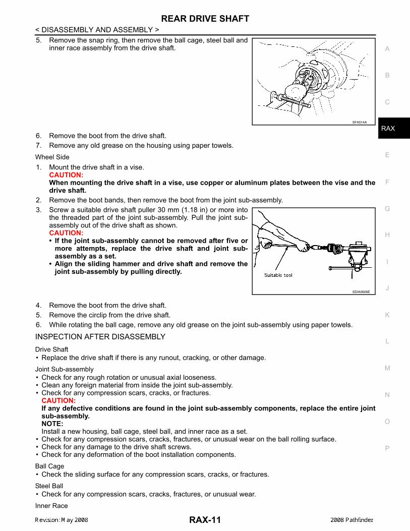
5. Remove the snap ring, then remove the ball cage, steel ball andinner race assembly from the drive shaft.
6. Remove the boot from the drive shaft.7. Remove any old grease on the housing using paper towels.Wheel Side1. Mount the drive shaft in a vise.
CAUTION:When mounting the drive shaft in a vise, use copper or aluminum plates between the vise and thedrive shaft.
2. Remove the boot bands, then remove the boot from the joint sub-assembly.3. Screw a suitable drive shaft puller 30 mm (1.18 in) or more into
the threaded part of the joint sub-assembly. Pull the joint sub-assembly out of the drive shaft as shown.CAUTION:• If the joint sub-assembly cannot be removed after five or
more attempts, replace the drive shaft and joint sub-assembly as a set.
• Align the sliding hammer and drive shaft and remove thejoint sub-assembly by pulling directly.
4. Remove the boot from the drive shaft.5. Remove the circlip from the drive shaft.6. While rotating the ball cage, remove any old grease on the joint sub-assembly using paper towels.
INSPECTION AFTER DISASSEMBLYDrive Shaft• Replace the drive shaft if there is any runout, cracking, or other damage.Joint Sub-assembly• Check for any rough rotation or unusual axial looseness.• Clean any foreign material from inside the joint sub-assembly.• Check for any compression scars, cracks, or fractures.
CAUTION:If any defective conditions are found in the joint sub-assembly components, replace the entire jointsub-assembly.NOTE:Install a new housing, ball cage, steel ball, and inner race as a set.
• Check for any compression scars, cracks, fractures, or unusual wear on the ball rolling surface.• Check for any damage to the drive shaft screws.• Check for any deformation of the boot installation components.Ball Cage• Check the sliding surface for any compression scars, cracks, or fractures.Steel Ball• Check for any compression scars, cracks, fractures, or unusual wear.Inner Race
SFA514A
SDIA0606E
RAX-11
REAR DRIVE SHAFT
< DISASSEMBLY AND ASSEMBLY >• Check the ball sliding surface for any compression scars, cracks, or fractures.• Check for any damage to the serrated part.
ASSEMBLYFinal Drive Side1. If the plug has been removed, use Tool to press in a new one.
NOTE:Discard the old plug and use a new one for assembly.
2. Wrap the serrated part of the shaft with tape. Install the bootband and boot to shaft.NOTE:Discard the old boot band and boot and use a new one forassembly.
3. Remove the tape wound around the serrated part of the shaft.
4. Install the ball cage, steel ball, and inner race assembly on theshaft, and secure them tightly using the snap ring.NOTE:Discard the old snap ring and use a new one for assembly.
5. Insert the specified quantity of Genuine NISSAN Grease orequivalent, onto the housing (indicated by * marks), and install itonto shaft. Refer to MA-10, "Fluids and Lubricants".
6. Install the stopper ring onto the housing.7. After installation, pull on the shaft to check engagement between the joint sub-assembly and the stopper
ring.
Tool number : KV38100500 ( — ): KV38102200 ( — )
SDIA1153E
SFA800
SDIA1125E
Grease capacity : 155 − 175 g (5.47 − 6.17 oz)
RAC0678D
RAX-12
REAR DRIVE SHAFT
C
E
F
G
H
I
J
K
L
M
A
B
AX
N
O
P
< DISASSEMBLY AND ASSEMBLY >
R
8. Install the boot securely into the grooves (indicated by * marks)as shown.CAUTION:If there is grease on boot mounting surfaces (indicated by*marks) of shaft and housing, boot may come off. Removeall grease from surfaces.
9. Check that the boot installation length “L” is the length indicatedbelow. Insert a flat-bladed screwdriver or similar tool into largerside of boot. Bleed the air from the boot to prevent any bootdeformation.
CAUTION:• The boot may break if the boot installation length is less than the specified value.• Do not to touch the tip of the screwdriver to the inside of the boot.
10. Secure the large and small ends of the boot with the new bootbands as shown. NOTE:Discard the old boot bands and use new ones for assembly.
11. After installing the housing and shaft, rotate the boot to check that the boot is positioned correctly. If theboot is not positioned correctly, reposition the boot and secure the boot using a new boot band.
Wheel Side1. Insert the Genuine NISSAN Grease or equivalent, into the joint
sub-assembly serration hole until the grease begins to oozefrom the ball groove and serration hole. Refer to MA-10, "Fluidsand Lubricants". After inserting the grease, use a shop cloth towipe off the grease that has oozed out.
2. Wind the serrated part of the shaft with tape. Install the bootband and boot onto the shaft. Do not damage the boot.NOTE:Discard the old boot band and boot and use a new one forassembly.
3. Remove the protective tape wound around the serrated part ofthe shaft.
Boot installation length “L” : 148.7 mm (5.85 in)WDIA0287E
SFA395
SDIA1127E
SFA800
RAX-13
REAR DRIVE SHAFT
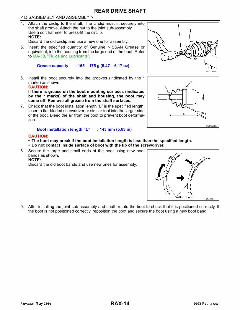
< DISASSEMBLY AND ASSEMBLY >4. Attach the circlip to the shaft. The circlip must fit securely into
the shaft groove. Attach the nut to the joint sub-assembly.Use a soft hammer to press-fit the circlip.NOTE:Discard the old circlip and use a new one for assembly.
5. Insert the specified quantity of Genuine NISSAN Grease orequivalent, into the housing from the large end of the boot. Referto MA-10, "Fluids and Lubricants".
6. Install the boot securely into the grooves (indicated by the *marks) as shown.CAUTION:If there is grease on the boot mounting surfaces (indicatedby the * marks) of the shaft and housing, the boot maycome off. Remove all grease from the shaft surfaces.
7. Check that the boot installation length “L” is the specified length.Insert a flat-bladed screwdriver or similar tool into the larger sideof the boot. Bleed the air from the boot to prevent boot deforma-tion.
CAUTION:• The boot may break if the boot installation length is less than the specified length.• Do not contact inside surface of boot with the tip of the screwdriver.
8. Secure the large and small ends of the boot using new bootbands as shown.NOTE:Discard the old boot bands and use new ones for assembly.
9. After installing the joint sub-assembly and shaft, rotate the boot to check that it is positioned correctly. Ifthe boot is not positioned correctly, reposition the boot and secure the boot using a new boot band.


![ENGINE STR A · 2017. 2. 25. · < SYSTEM DESCRIPTION > [VQ35DE] STARTING SYSTEM SYSTEM DESCRIPTION STARTING SYSTEM System Diagram INFOID:0000000007255932 System Description](https://static.documents.pub/doc/80x56/61331345dfd10f4dd73adac1/engine-str-a-2017-2-25-system-description-vq35de-starting-system.jpg)


