Transmission Line Protection – End to End Testing Chris Gallacher – Protection Engineer Greg Sharpes – Senior Relay Technician Mark Babin – Senior Relay Technician Hands on Relay School, March 15, 2018
• Why do you need Communications Aided/Based Tripping Schemes?
• How do you build one? Design.
• Are you sure it works? Testing.
• What can go wrong? Troubleshooting.
• The fun part. Lab Testing.
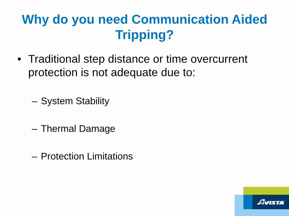
Why do you need Communication Aided Tripping?
Why do you need Communication Aided Tripping?
• Traditional step distance or time overcurrent protection is not adequate due to:
– System Stability
– Thermal Damage
– Protection Limitations
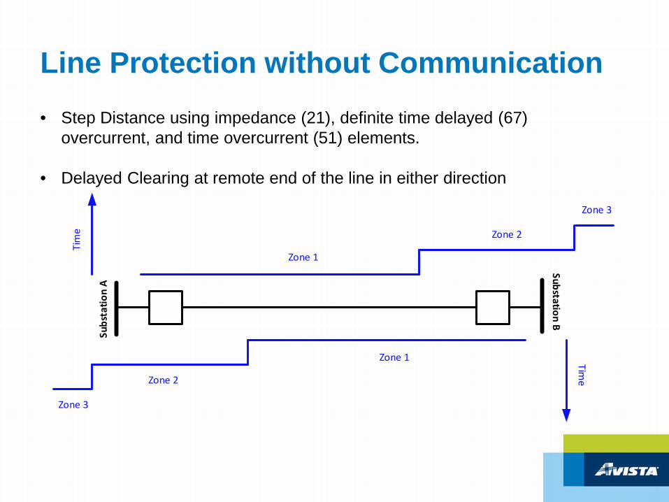
Line Protection without Communication• Step Distance using impedance (21), definite time delayed (67)
overcurrent, and time overcurrent (51) elements.
• Delayed Clearing at remote end of the line in either direction
Subs
tatio
n A
Substation B
Time
Zone 1
Zone 2
Zone 3
Zone 1
Zone 2
Zone 3
Tim
e
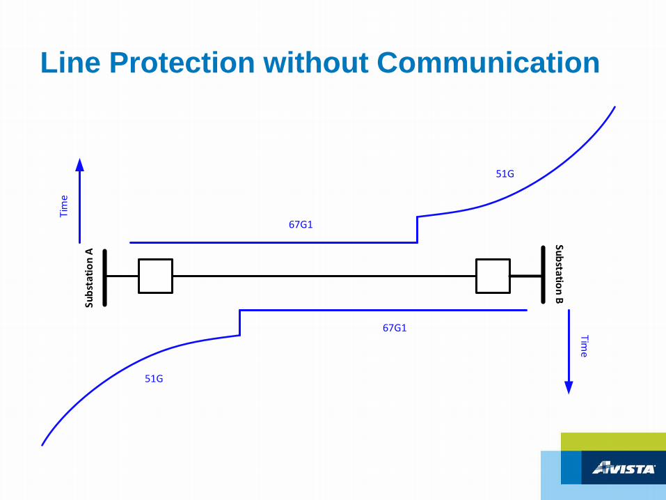
Line Protection without CommunicationSu
bsta
tion
A
Substation B
Time
67G1
67G1
Tim
e
51G
51G
How to build a Communication Aided/Based Protection Scheme?
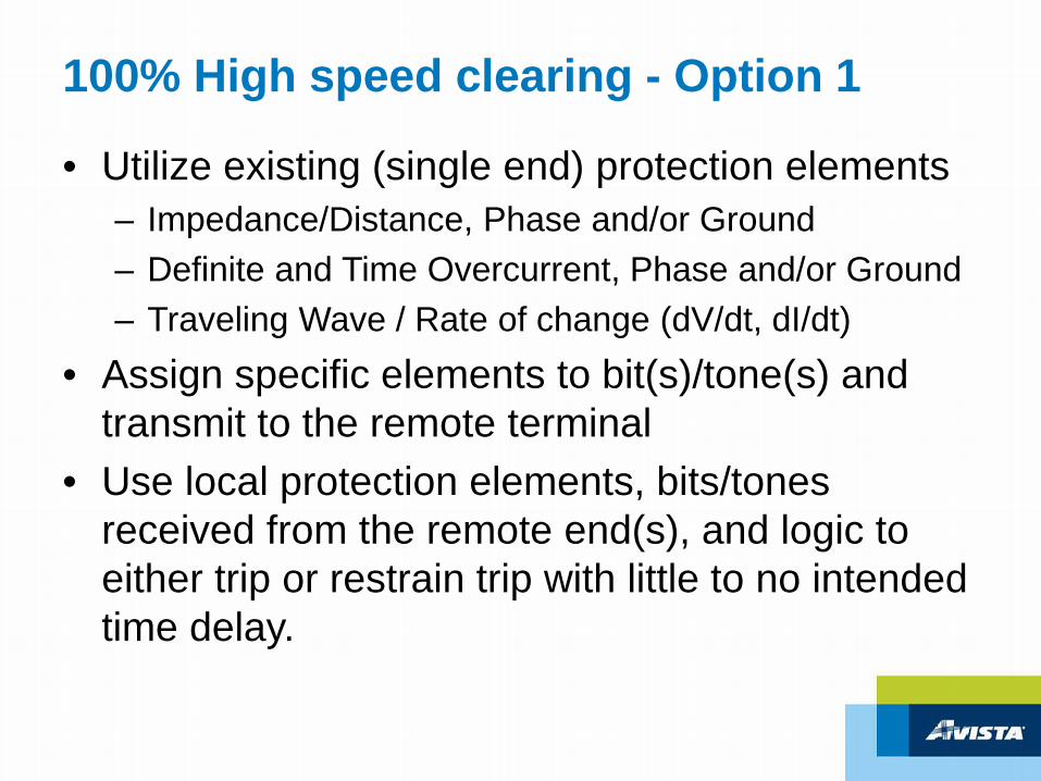
100% High speed clearing - Option 1
• Utilize existing (single end) protection elements– Impedance/Distance, Phase and/or Ground– Definite and Time Overcurrent, Phase and/or Ground– Traveling Wave / Rate of change (dV/dt, dI/dt)
• Assign specific elements to bit(s)/tone(s) and transmit to the remote terminal
• Use local protection elements, bits/tones received from the remote end(s), and logic to either trip or restrain trip with little to no intended time delay.
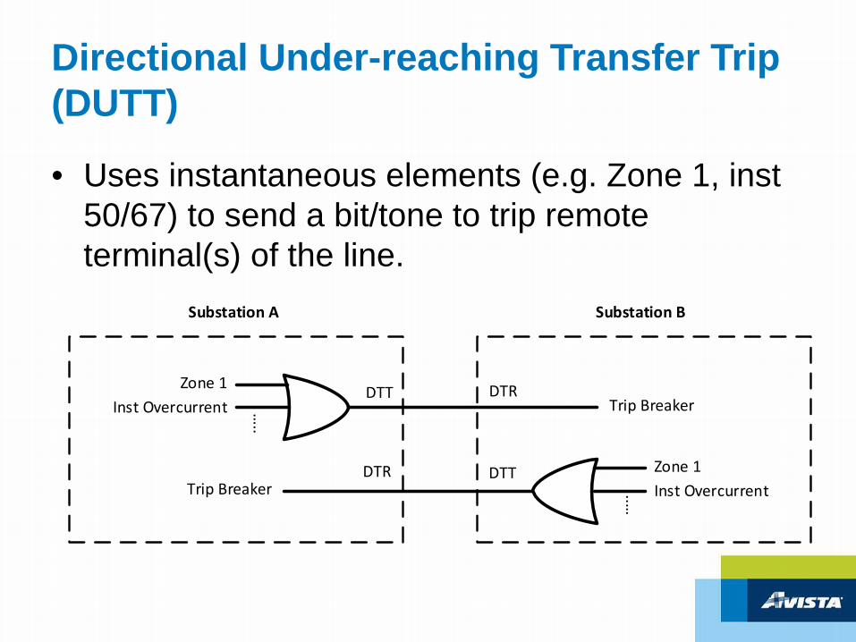
Directional Under-reaching Transfer Trip (DUTT)
• Uses instantaneous elements (e.g. Zone 1, inst50/67) to send a bit/tone to trip remote terminal(s) of the line.
Zone 1Inst Overcurrent …
..
DTTTrip Breaker
Zone 1Inst Overcurrent
…..
DTTTrip Breaker
DTR
Substation A Substation B
DTR
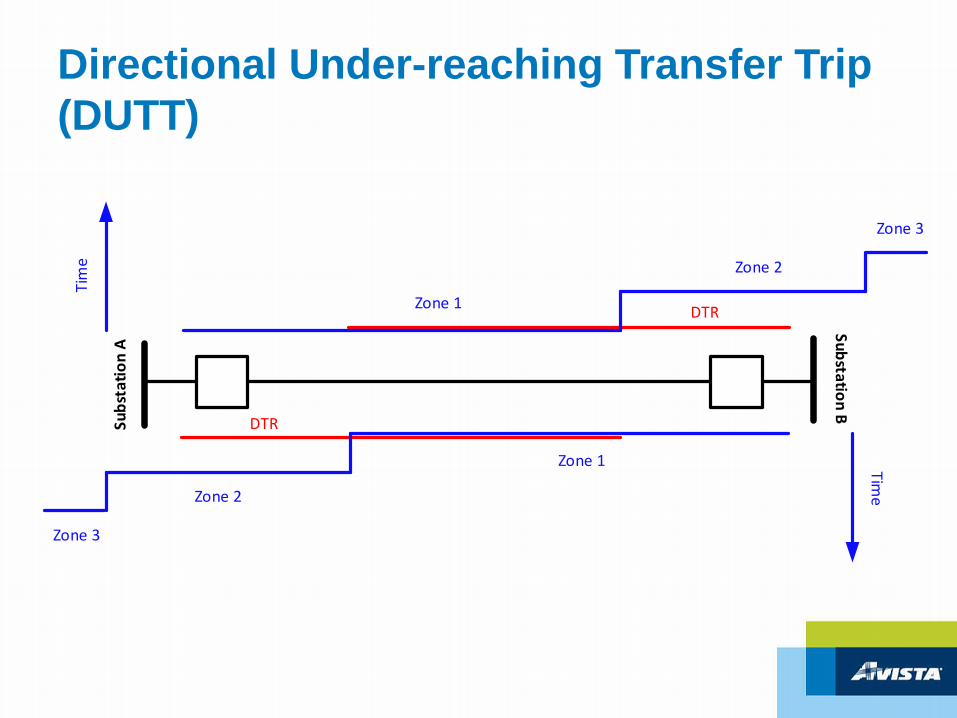
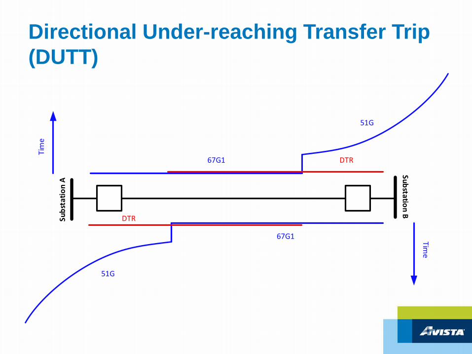
Directional Under-reaching Transfer Trip (DUTT)
DTR
DTR
Subs
tatio
n A
Substation B
Time
Zone 1
Zone 2
Zone 3
Zone 1
Zone 2
Zone 3
Tim
e
Directional Under-reaching Transfer Trip (DUTT)
Subs
tatio
n ASubstation B
Time
67G1
67G1
Tim
e
51G
51G
DTR
DTR
Permissive Over-reaching Transfer Trip (POTT)
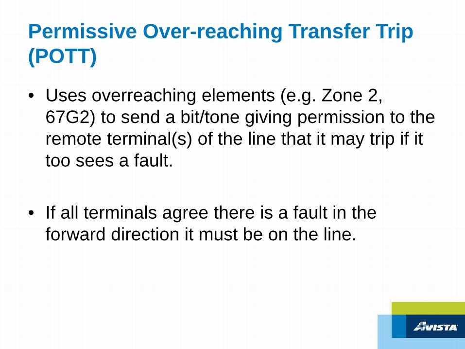
• Uses overreaching elements (e.g. Zone 2, 67G2) to send a bit/tone giving permission to the remote terminal(s) of the line that it may trip if it too sees a fault.
• If all terminals agree there is a fault in the forward direction it must be on the line.
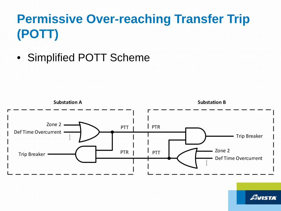
Permissive Over-reaching Transfer Trip (POTT)
• Simplified POTT Scheme
Zone 2Def Time Overcurrent …
..
PTT
Trip Breaker
Zone 2Def Time Overcurrent
…..
PTT
PTR
Substation A Substation B
PTRTrip Breaker
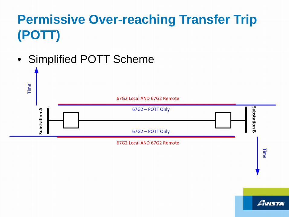
Permissive Over-reaching Transfer Trip (POTT)
Subs
tatio
n A
Substation B
Time
Zone 2 – POTT Only
Tim
e
Zone 2 – POTT Only
Zone 2 Local AND Zone 2 Remote
Zone 2 Local AND Zone 2 Remote
• Simplified POTT Scheme
Permissive Over-reaching Transfer Trip (POTT)
• Simplified POTT Scheme
Subs
tatio
n ASubstation B
Time
67G2 – POTT Only
Tim
e
67G2 – POTT Only
67G2 Local AND 67G2 Remote
67G2 Local AND 67G2 Remote
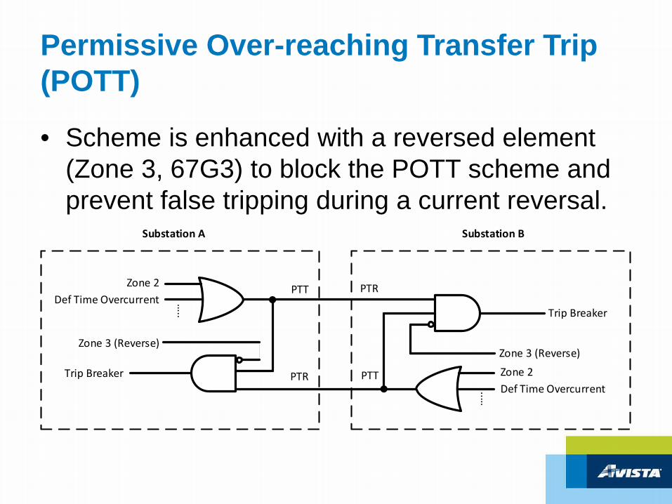
Permissive Over-reaching Transfer Trip (POTT)
• Scheme is enhanced with a reversed element (Zone 3, 67G3) to block the POTT scheme and prevent false tripping during a current reversal.
Zone 2Def Time Overcurrent …
..
PTT
Trip Breaker
Zone 2Def Time Overcurrent
…..
PTT
PTR
Substation A Substation B
PTRTrip Breaker
Zone 3 (Reverse)Zone 3 (Reverse)
Permissive Over-reaching Transfer Trip (POTT)
• Additional enhancements:
– Weak end infeed
– Echo back
– ‘b’ repeat
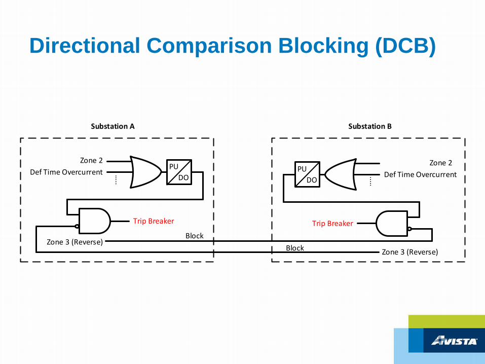
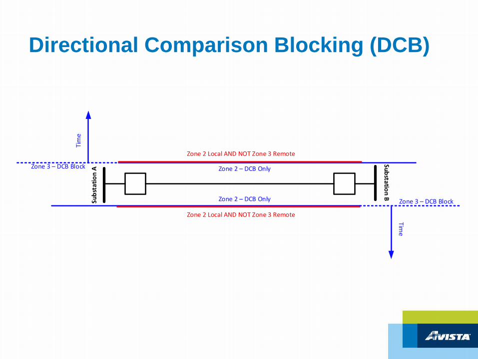
Directional Comparison Blocking (DCB)
• Uses a local overreaching element (e.g. Zone 2) to trip and a remote reversed element (e.g. Zone 3) to block the tripping element.
• Local overreaching element is briefly delayed (1 - 5 cycles) for communication latency, i.e. waits for a block signal
Directional Comparison Blocking (DCB)
Zone 2Def Time Overcurrent …
..
Substation A Substation B
Trip Breaker
Zone 3 (Reverse)Zone 3 (Reverse)
Zone 2Def Time Overcurrent
…..
Trip BreakerBlock
Block
PUDO
PUDO
Directional Comparison Blocking (DCB)
Subs
tatio
n A
Substation B
Time
Zone 2 – DCB Only
Tim
e
Zone 2 – DCB Only
Zone 2 Local AND NOT Zone 3 Remote
Zone 2 Local AND NOT Zone 3 Remote
Zone 3 – DCB Block
Zone 3 – DCB Block
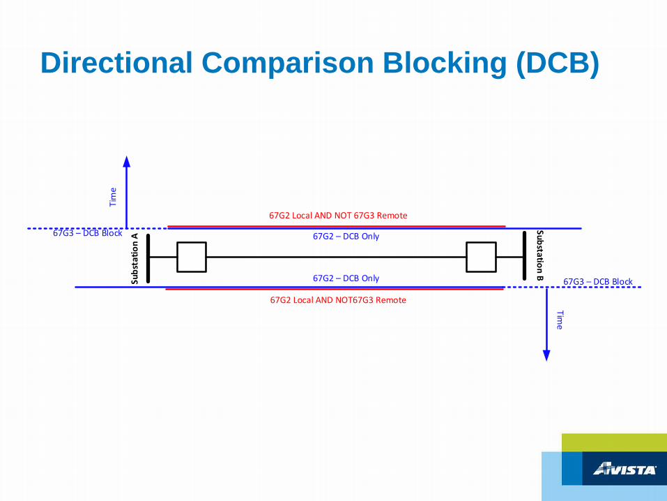
Directional Comparison Blocking (DCB)
Subs
tatio
n A
Substation B
Time
67G2 – DCB Only
Tim
e
67G2 – DCB Only
67G2 Local AND NOT 67G3 Remote
67G2 Local AND NOT67G3 Remote
67G3 – DCB Block
67G3 – DCB Block
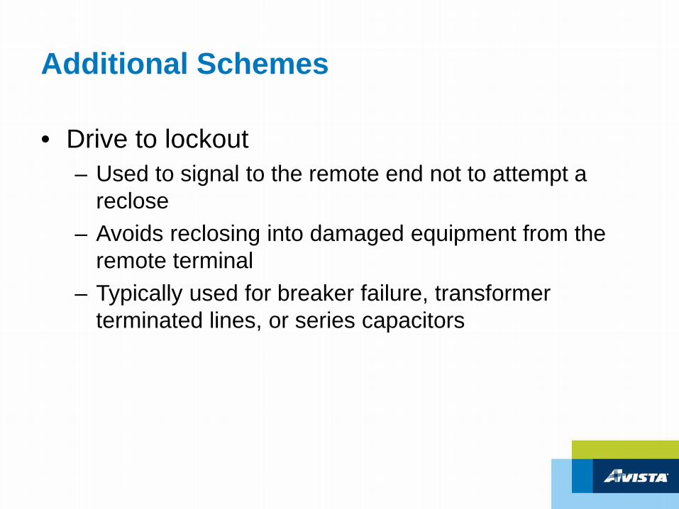
Additional Schemes
• Drive to lockout– Used to signal to the remote end not to attempt a
reclose– Avoids reclosing into damaged equipment from the
remote terminal– Typically used for breaker failure, transformer
terminated lines, or series capacitors
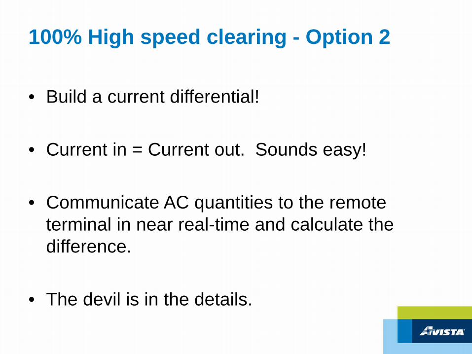
100% High speed clearing - Option 2
• Build a current differential!
• Current in = Current out. Sounds easy!
• Communicate AC quantities to the remote terminal in near real-time and calculate the difference.
• The devil is in the details.
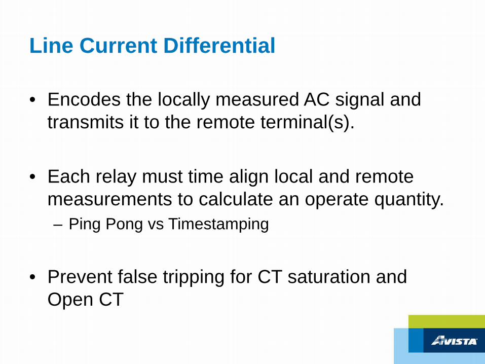
Line Current Differential
• Encodes the locally measured AC signal and transmits it to the remote terminal(s).
• Each relay must time align local and remote measurements to calculate an operate quantity.– Ping Pong vs Timestamping
• Prevent false tripping for CT saturation and Open CT
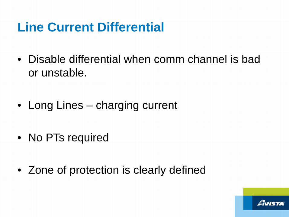
Line Current Differential
• Disable differential when comm channel is bad or unstable.
• Long Lines – charging current
• No PTs required
• Zone of protection is clearly defined
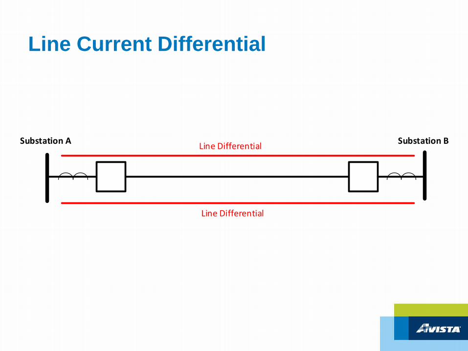
Line Current Differential
Substation A Substation BLine Differential
Line Differential
Communication Systems
• Different schemes require certain levels of communication service:– Could the communication channel be effected during
a fault?– Does the scheme require comm during a fault to
work?– What is the channel latency?– Is channel latency consistent? Deterministic.– Is the channel latency the same in both directions?
Asymmetry.
The Buddy System of Line Protection
Are you sure it works?
Testing
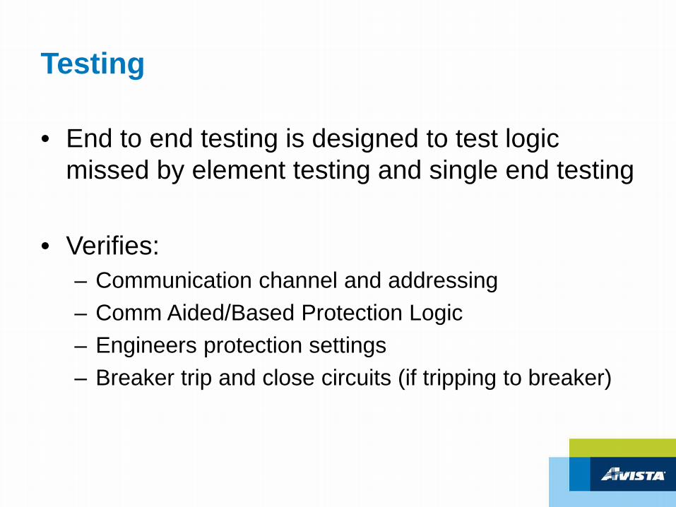
• End to end testing is designed to test logic missed by element testing and single end testing
• Verifies:– Communication channel and addressing– Comm Aided/Based Protection Logic– Engineers protection settings– Breaker trip and close circuits (if tripping to breaker)
End to End Testing
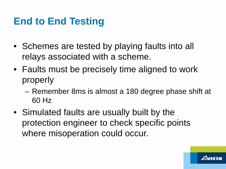
• Schemes are tested by playing faults into all relays associated with a scheme.
• Faults must be precisely time aligned to work properly– Remember 8ms is almost a 180 degree phase shift at
60 Hz• Simulated faults are usually built by the
protection engineer to check specific points where misoperation could occur.
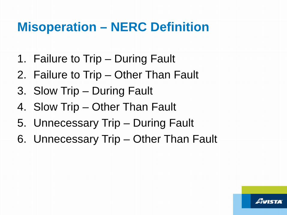
Misoperation – NERC Definition
1. Failure to Trip – During Fault2. Failure to Trip – Other Than Fault3. Slow Trip – During Fault4. Slow Trip – Other Than Fault 5. Unnecessary Trip – During Fault6. Unnecessary Trip – Other Than Fault
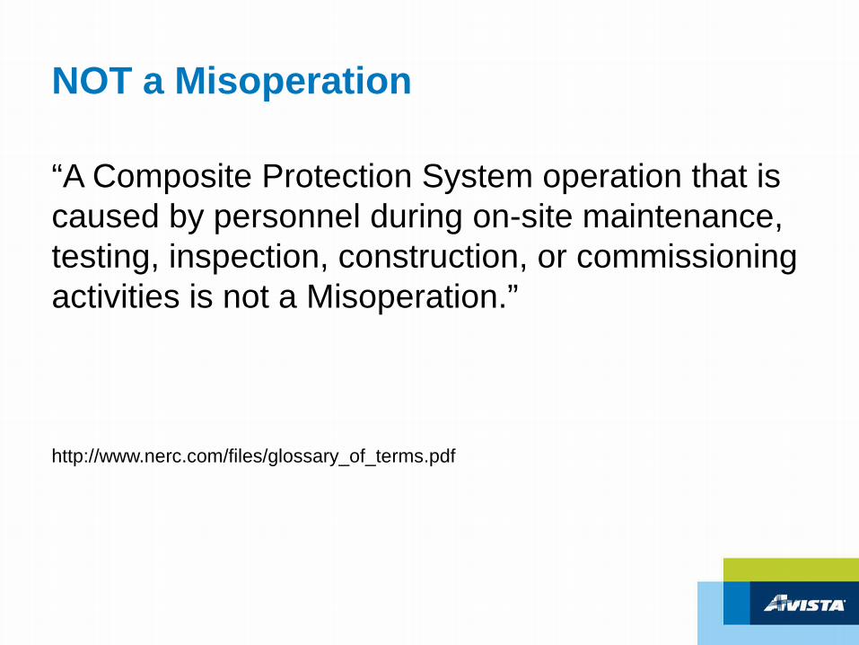
NOT a Misoperation
“A Composite Protection System operation that is caused by personnel during on-site maintenance, testing, inspection, construction, or commissioning activities is not a Misoperation.”
http://www.nerc.com/files/glossary_of_terms.pdf
Typical Line
Substation A Substation B
Relay A Relay BCommunication Medium:
PLC, Direct Fiber, Copper,SONET, Packet Switched, etc
Trip
Close
Communication Channel
Communication Channel
Trip
Close
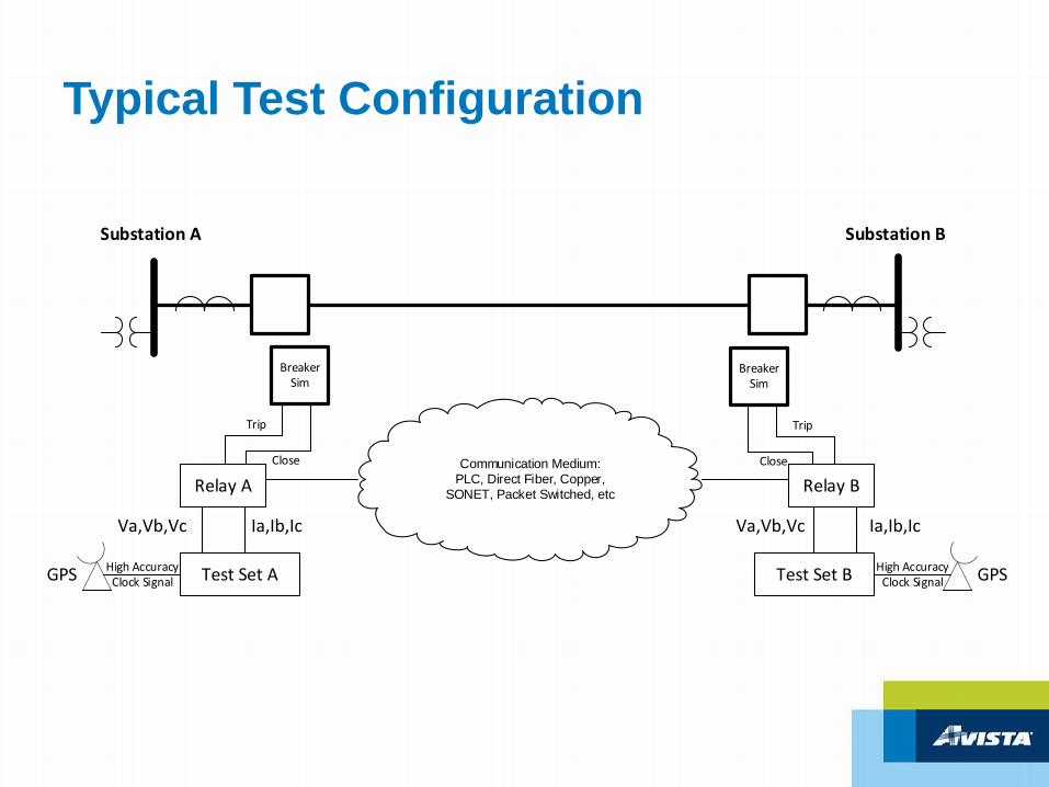
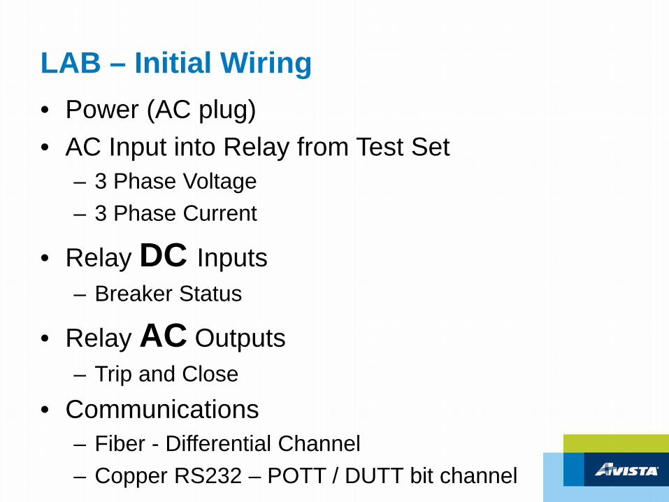
Typical Test Configuration
Substation A Substation B
Relay A Relay BCommunication Medium:
PLC, Direct Fiber, Copper,SONET, Packet Switched, etc
Test Set A Test Set B
Ia,Ib,IcVa,Vb,Vc Ia,Ib,IcVa,Vb,Vc
GPS High Accuracy Clock Signal GPSHigh Accuracy
Clock Signal
Breaker Sim
Trip
Close
Breaker Sim
Trip
Close
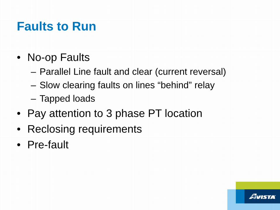
Faults to Run
• Both Phase (3LG, LL) and Ground (SLG, 2LG)• Possibly different phases of the same fault if
single pole tripping– Phase segregated direct trip or permissive trips
• Fault at points where scheme is need for high speed clearing– Mid line, high impedance fault.– Line end
Faults to Run
• No-op Faults– Parallel Line fault and clear (current reversal)– Slow clearing faults on lines “behind” relay– Tapped loads
• Verify testing setup– Is the relay seeing ABC rotation of voltage and
current?– Can the relay trip/close the “breaker”?– Are the relays communicating?
• Differential• POTT / DUTT
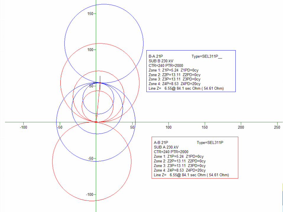
Protection Design – Phase Elements
• 4 Mho Phase Distance– Zone 1 – Instantaneous trip (80% of line)– Zone 2 – POTT Keying Only (200% of line)– Zone 3 – POTT Reverse Blocking (200% of line)– Zone 4 – Traditional Zone 2 (120% of line)
• 20 cycle delay
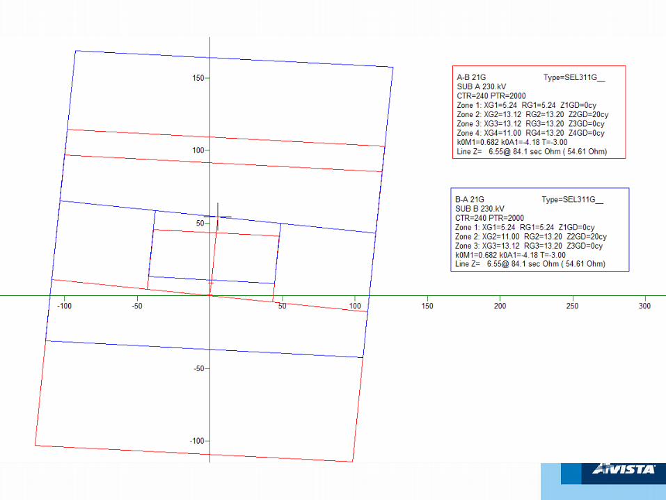
Protection Design – Ground Elements
• 4 Quadrilateral Ground Distance– Zone 1 – Instantaneous trip (80% of line)– Zone 2 – POTT Keying Only (200% of line)– Zone 3 – POTT Reverse Blocking (200% of line)– Zone 4 – Traditional Zone 2 (120% of line)