69
Transmission Lines, Antenna Tuners, and Impedance Matching Matching 3/12/2009 Larry Benko, W0QE 1

Transmission Lines, Antenna Tuners, and Impedance
MatchingMatching
3/12/2009 Larry Benko, W0QE 1
Understanding Transmission Lines
• Presentation about antenna tuners and impedance matching will follow
• Need to understand transmission lines first• Need to understand transmission lines first• Concepts are interdependent and not separable• Software simulation is invaluable for better
understanding of the concepts• Inexpensive test equipment allows measurements
that only a lab could make 10 years ago
3/12/2009 Larry Benko, W0QE 2
Transmission Lines and Coaxial Cable
• Deliver RF signals to another location efficiently• Early transmitters did not use transmission lines• 2/4 wire open wire lines, flexible coax, hard line,
twisted pair, microstrip, wave guide, etc.• Computer motherboards, Ethernet, USB cables• Nearly all digital signals are RF these days
3/12/2009 Larry Benko, W0QE 3

Who Can You Believe?
• Too much misinformation and incomplete information exists
• Transient conditions and steady state are often • Transient conditions and steady state are often mixed together which is incorrect
• All concepts presented have been measured in hardware and simulated in software, often in multiple programs, with total agreement
• Please challenge me on any topic
3/12/2009 Larry Benko, W0QE 4
Software Tools(free except EZNec, WinSmith and TLW)
• LTspice IV (previously SwitcherCAD) – http://www.linear.com/designtools/software/
• TLW v3.0 on ARRL Antenna Handbook CDROM• TLW v3.0 on ARRL Antenna Handbook CDROM• WinSmith 2.0
– http://www.scitechpublishing.com
• Collection of Smith Chart stuff– http://sss-mag.com/smith.html
• SuperSmith– http://www.tonnesoftware.com/
3/12/2009 Larry Benko, W0QE 5

Software Tools(free except EZNec, WinSmith and TLW)
• VNA Help SWR Calculator– http://www.vnahelp.com/products.html
• RFSim99– http://www.practicalrf.com/$Newsletter/e-– http://www.practicalrf.com/$Newsletter/e-
letters/February2006/RFSim99.htm• EZNEC
– http://www.eznec.com– other NEC programs 4NEC2, NEC4Win etc.
• Coax loss & power handling calculator– http://www.timesmicrowave.com/cgi-bin/calculate.pl
3/12/2009 Larry Benko, W0QE 6

Hardware Tools
• AIM4170B Antenna Analyzer– http://www.arraysolutions.com/Products/AIM4170B.htm– Several other good analyzers available– Several other good analyzers available
• Time Domain Reflectometer (home brew)
3/12/2009 Larry Benko, W0QE 7
Weaknesses in Software Tools• LTSpice:
– Transmission line loss constant with frequency– Q of components is constant with frequency– Can’t model transmission line shielding– Can’t model transmission line shielding
• TLW:– Q of components is constant with frequency
• WinSmith:– Transmission line loss is constant with frequency
• Weaknesses are minimal
3/12/2009 Larry Benko, W0QE 8
How Do Transmission Lines Work?• At every point along the line the currents in each
wire are the same magnitude and 180 degrees out of phase
• For coax, the currents are on the outside of the • For coax, the currents are on the outside of the center conductor and the inside of the shield
• AC current flow produces a magnetic field that opposes current flow
• Transmission line currents produce the minimum magnetic field which also minimizes radiation
3/12/2009 Larry Benko, W0QE 9
Other Currents on the Line
• A current can flow on both wires equally and is in phase for open wire line or on the outside of the shield for coaxshield for coax
• This is an antenna current that does radiate and is generally unwanted
• Common mode chokes are used to keep this current at acceptable levels
3/12/2009 Larry Benko, W0QE 10
Terminology of Currents
• Transmission line currents are also known as differential or metallic currents
• Common mode currents are also known as • Common mode currents are also known as longitudinal or antenna currents
• Both types of currents can coexist but there is always a small conversion from one type to the other which can cause problems
3/12/2009 Larry Benko, W0QE 11
Properties of coaxial cable• Characteristic impedance• Attenuation (matched loss) vs. frequency• Power rating (current rating) matched vs. frequency• Dielectric material (voltage breakdown, temperature rating)• Center conductor (size and composition)• Shield(s) material (shielding effectiveness)• Outside jacket (weather, temperature, abrasion rating)• Minimum bend radius, flexibility• Physical size and connector compatibility• Velocity factor• Not all properties are important for a particular application
3/12/2009 Larry Benko, W0QE 12
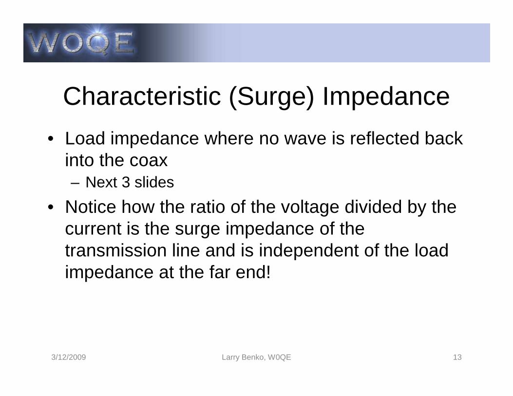
Characteristic (Surge) Impedance
• Load impedance where no wave is reflected back into the coax– Next 3 slides
• Notice how the ratio of the voltage divided by the • Notice how the ratio of the voltage divided by the current is the surge impedance of the transmission line and is independent of the load impedance at the far end!
3/12/2009 Larry Benko, W0QE 13
3/12/2009 Larry Benko, W0QE 14
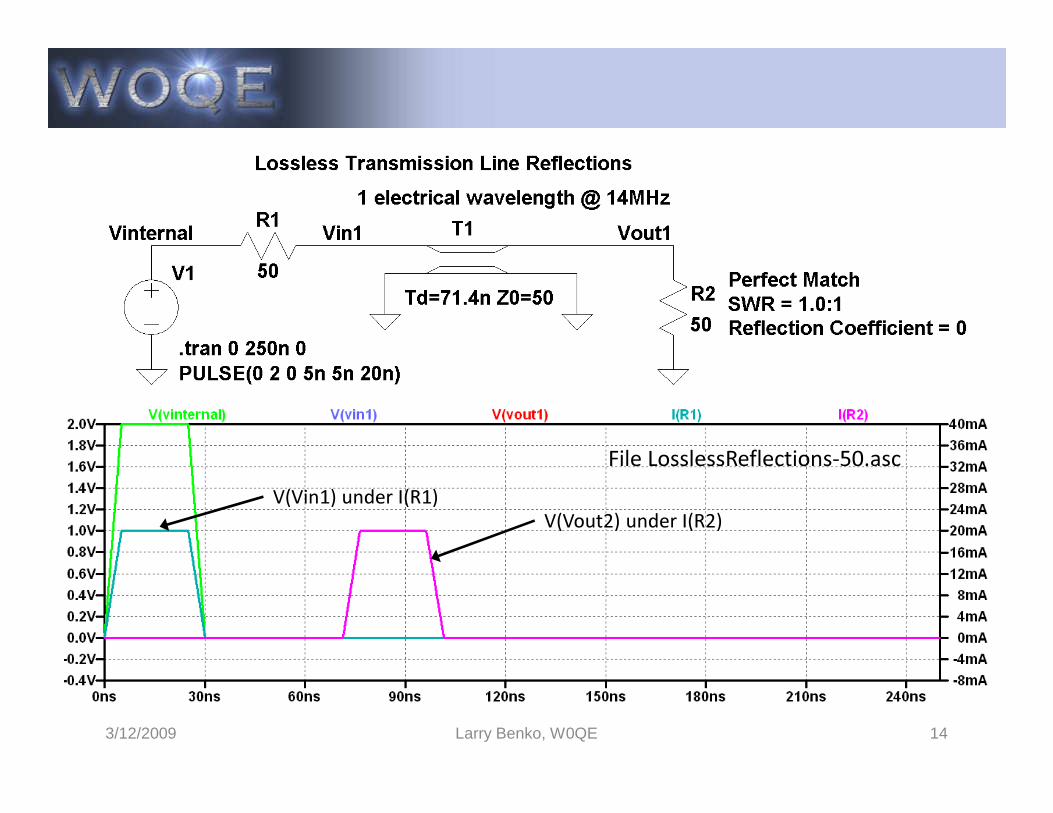
File LosslessReflections-50.ascV(Vin1) under I(R1)
V(Vout2) under I(R2)
3/12/2009 Larry Benko, W0QE 15
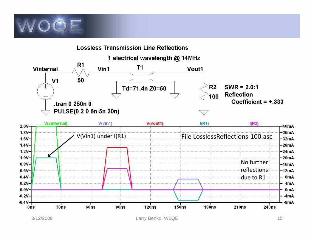
File LosslessReflections-100.ascV(Vin1) under I(R1)
No further reflections due to R1
3/12/2009 Larry Benko, W0QE 16
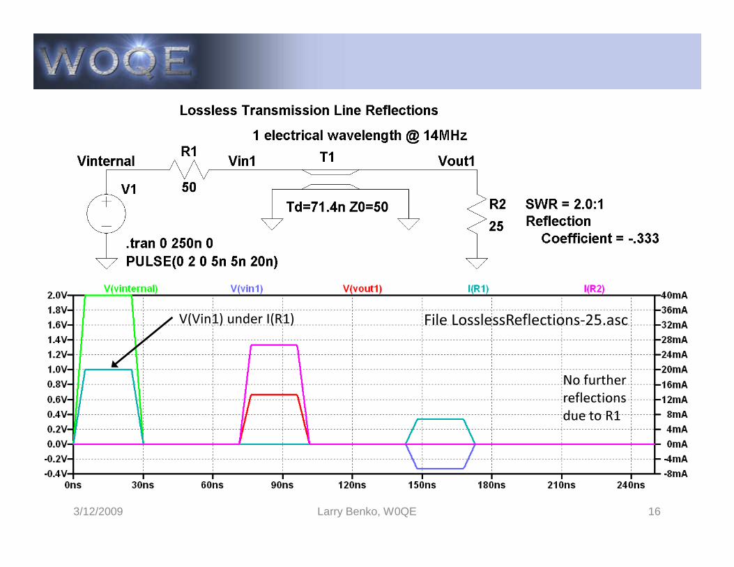
File LosslessReflections-25.ascV(Vin1) under I(R1)
No further reflections due to R1
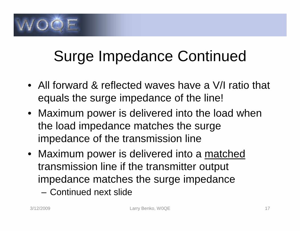
Surge Impedance Continued
• All forward & reflected waves have a V/I ratio that equals the surge impedance of the line!
• Maximum power is delivered into the load when • Maximum power is delivered into the load when the load impedance matches the surge impedance of the transmission line
• Maximum power is delivered into a matchedtransmission line if the transmitter output impedance matches the surge impedance– Continued next slide
3/12/2009 Larry Benko, W0QE 17
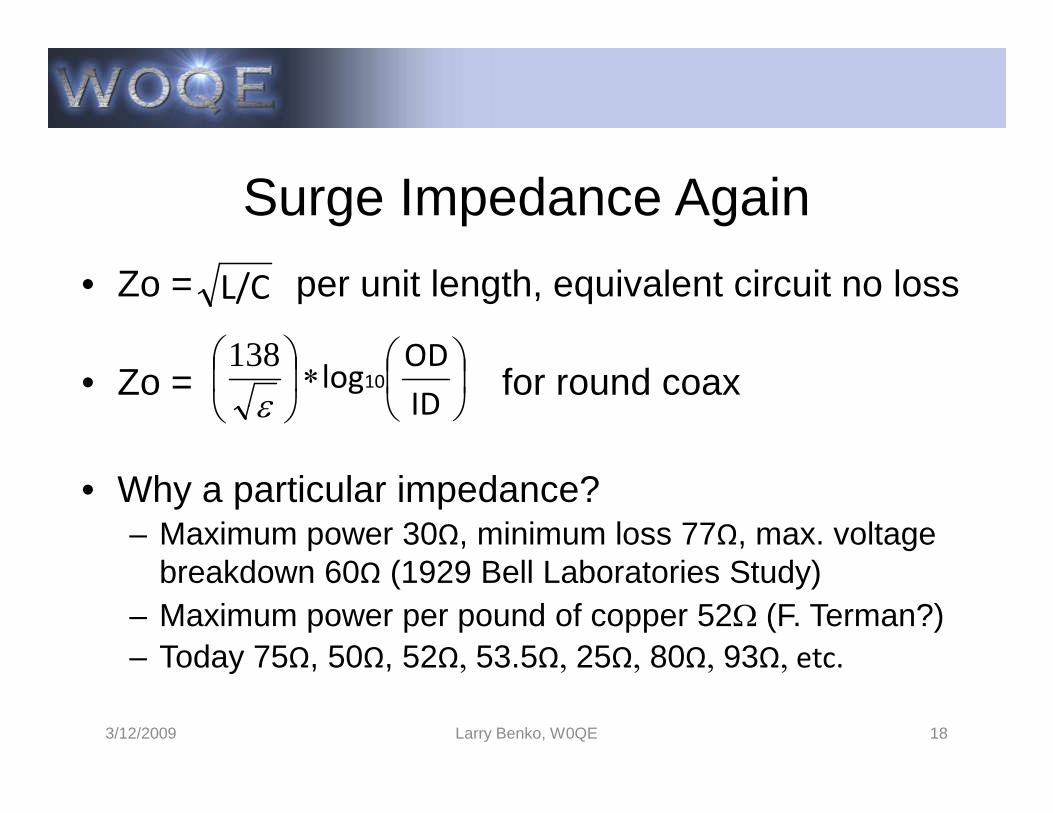
Surge Impedance Again
• Zo = per unit length, equivalent circuit no loss
• Zo = for round coax
L/C
∗
IDODlog10
ε
138
• Why a particular impedance?– Maximum power 30Ω, minimum loss 77Ω, max. voltage
breakdown 60Ω (1929 Bell Laboratories Study)– Maximum power per pound of copper 52Ω (F. Terman?)– Today 75Ω, 50Ω, 52Ω, 53.5Ω, 25Ω, 80Ω, 93Ω, etc.
3/12/2009 Larry Benko, W0QE 18
IDε
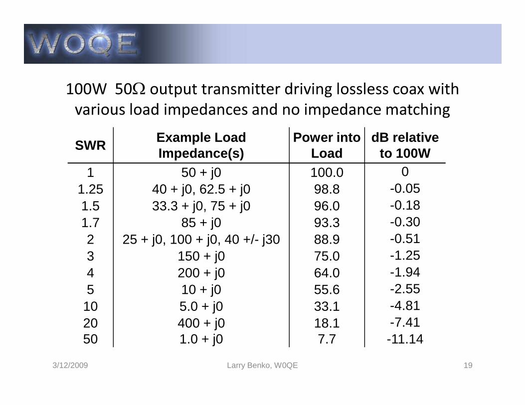
100W 50Ω output transmitter driving lossless coax with various load impedances and no impedance matchingSWR
Example Load Impedance(s)
Power into Load
dB relative to 100W
1 50 + j0 100.0 01.25 40 + j0, 62.5 + j0 98.8 -0.051.5 33.3 + j0, 75 + j0 96.0 -0.18
3/12/2009 Larry Benko, W0QE 19
1.5 33.3 + j0, 75 + j0 96.0 -0.181.7 85 + j0 93.3 -0.302 25 + j0, 100 + j0, 40 +/- j30 88.9 -0.513 150 + j0 75.0 -1.254 200 + j0 64.0 -1.945 10 + j0 55.6 -2.55
10 5.0 + j0 33.1 -4.8120 400 + j0 18.1 -7.4150 1.0 + j0 7.7 -11.14
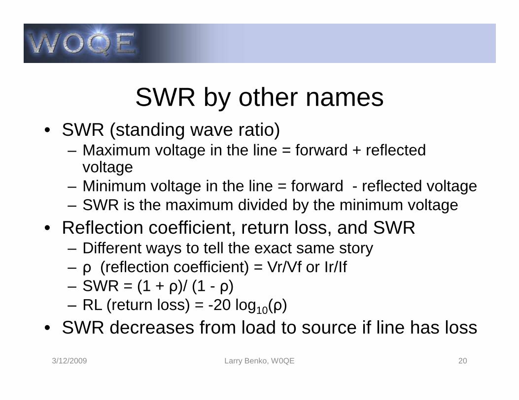
SWR by other names• SWR (standing wave ratio)
– Maximum voltage in the line = forward + reflected voltage
– Minimum voltage in the line = forward - reflected voltage– SWR is the maximum divided by the minimum voltage– SWR is the maximum divided by the minimum voltage
• Reflection coefficient, return loss, and SWR– Different ways to tell the exact same story– ρ (reflection coefficient) = Vr/Vf or Ir/If– SWR = (1 + ρ)/ (1 - ρ)– RL (return loss) = -20 log10(ρ)
• SWR decreases from load to source if line has loss
3/12/2009 Larry Benko, W0QE 20
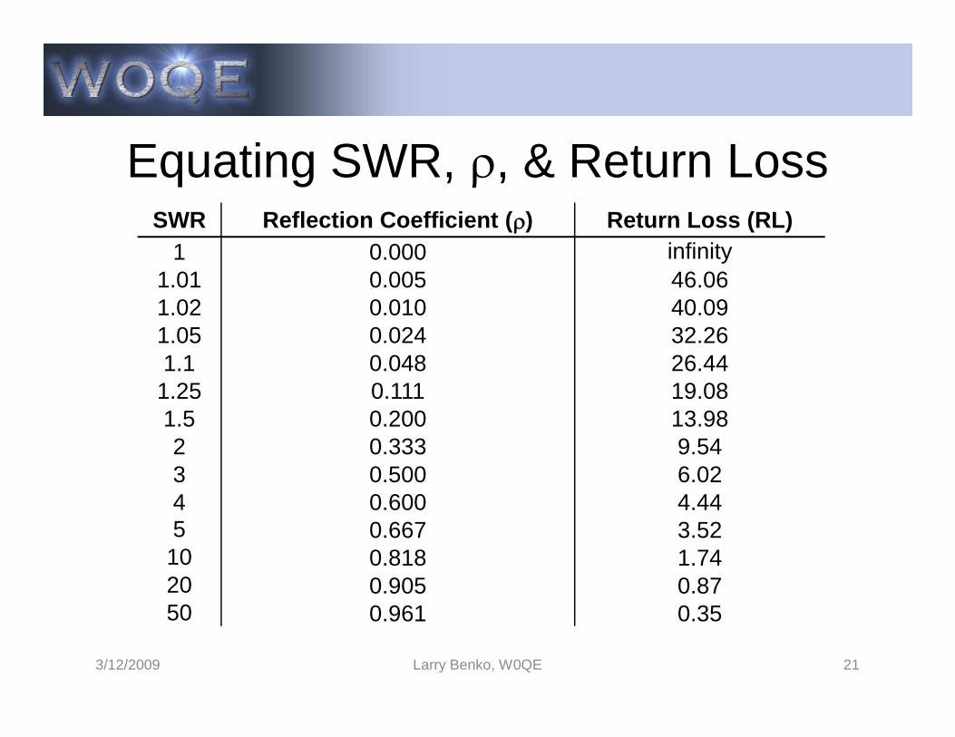
Equating SWR, ρ, & Return LossSWR Reflection Coefficient (ρ) Return Loss (RL)
1 0.000 infinity1.01 0.005 46.061.02 0.010 40.091.05 0.024 32.261.1 0.048 26.44
3/12/2009 Larry Benko, W0QE 21
1.1 0.048 26.441.25 0.111 19.081.5 0.200 13.982 0.333 9.543 0.500 6.024 0.600 4.445 0.667 3.52
10 0.818 1.7420 0.905 0.8750 0.961 0.35
Effect of Reflections
• For continuous transmissions the signals reflected back into the transmission line can arrive at the transmitter with an amplitude from arrive at the transmitter with an amplitude from zero to the original transmitter amplitude and at any phase angle
• The impedance seen by the transmitter varies and for high SWRs can be either very low or high causing driving problems for the transmitter
3/12/2009 Larry Benko, W0QE 22
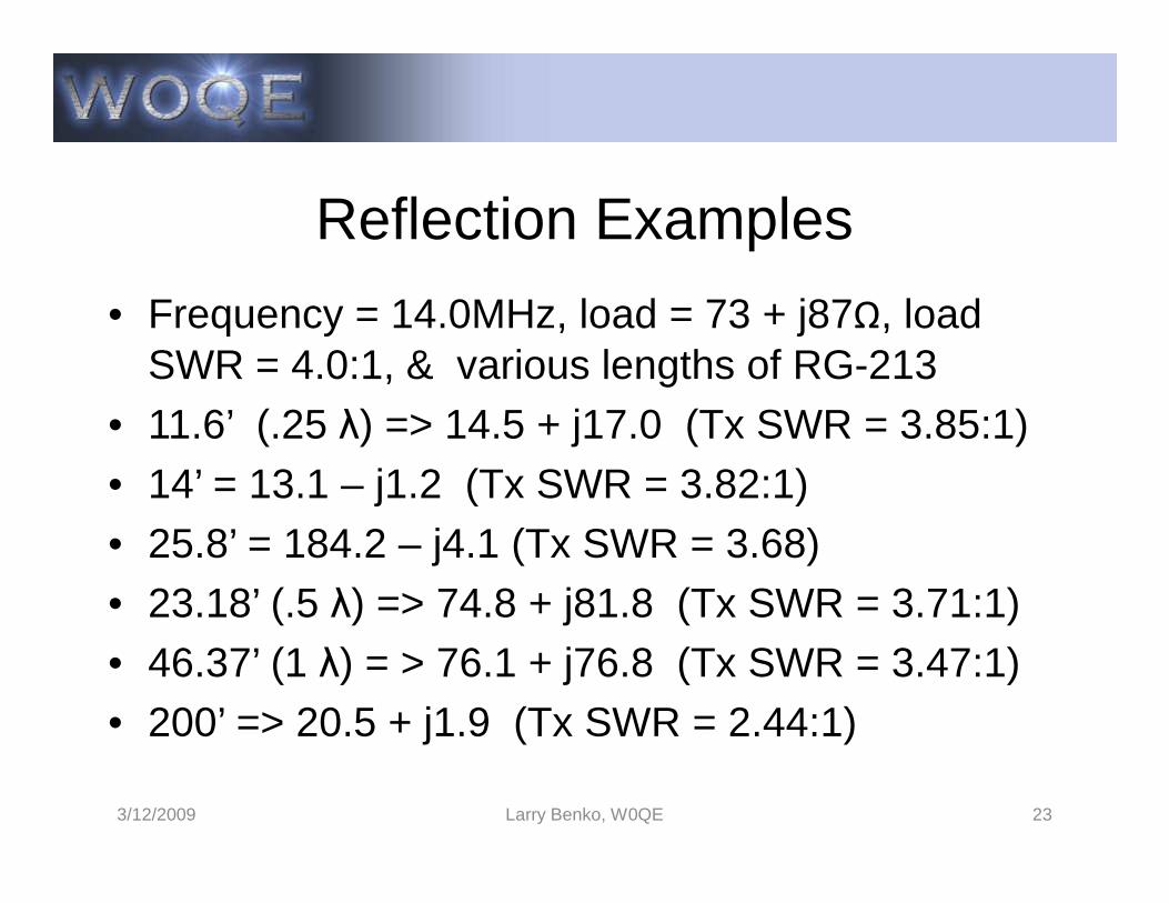
Reflection Examples
• Frequency = 14.0MHz, load = 73 + j87Ω, load SWR = 4.0:1, & various lengths of RG-213
• 11.6’ (.25 λ) => 14.5 + j17.0 (Tx SWR = 3.85:1)• 14’ = 13.1 – j1.2 (Tx SWR = 3.82:1)• 25.8’ = 184.2 – j4.1 (Tx SWR = 3.68)• 23.18’ (.5 λ) => 74.8 + j81.8 (Tx SWR = 3.71:1)• 46.37’ (1 λ) = > 76.1 + j76.8 (Tx SWR = 3.47:1)• 200’ => 20.5 + j1.9 (Tx SWR = 2.44:1)
3/12/2009 Larry Benko, W0QE 23

Loss
• At HF loss in coax is predominantly due to the RF resistance of the center conductor
• Matched loss at HF is frequency dependent and • Matched loss at HF is frequency dependent and increases ~ as the square root of frequency
• Following example shows losses with and without matching for a 100W transmitter
3/12/2009 Larry Benko, W0QE 24
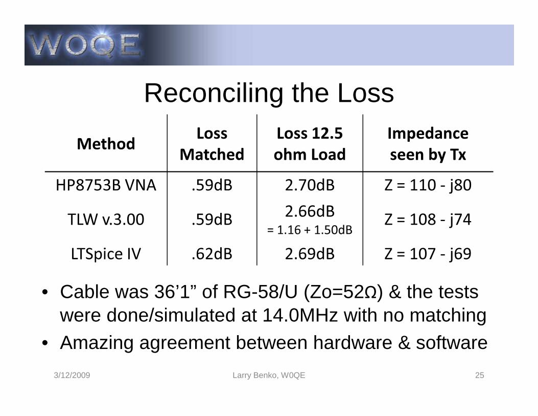
Reconciling the Loss
Method LossMatched
Loss 12.5ohm Load
Impedanceseen by Tx
HP8753B VNA .59dB 2.70dB Z = 110 - j80TLW v.3.00 .59dB 2.66dB Z = 108 - j74
3/12/2009 Larry Benko, W0QE 25
• Cable was 36’1” of RG-58/U (Zo=52Ω) & the tests were done/simulated at 14.0MHz with no matching
• Amazing agreement between hardware & software
TLW v.3.00 .59dB 2.66dB= 1.16 + 1.50dB Z = 108 - j74
LTSpice IV .62dB 2.69dB Z = 107 - j69
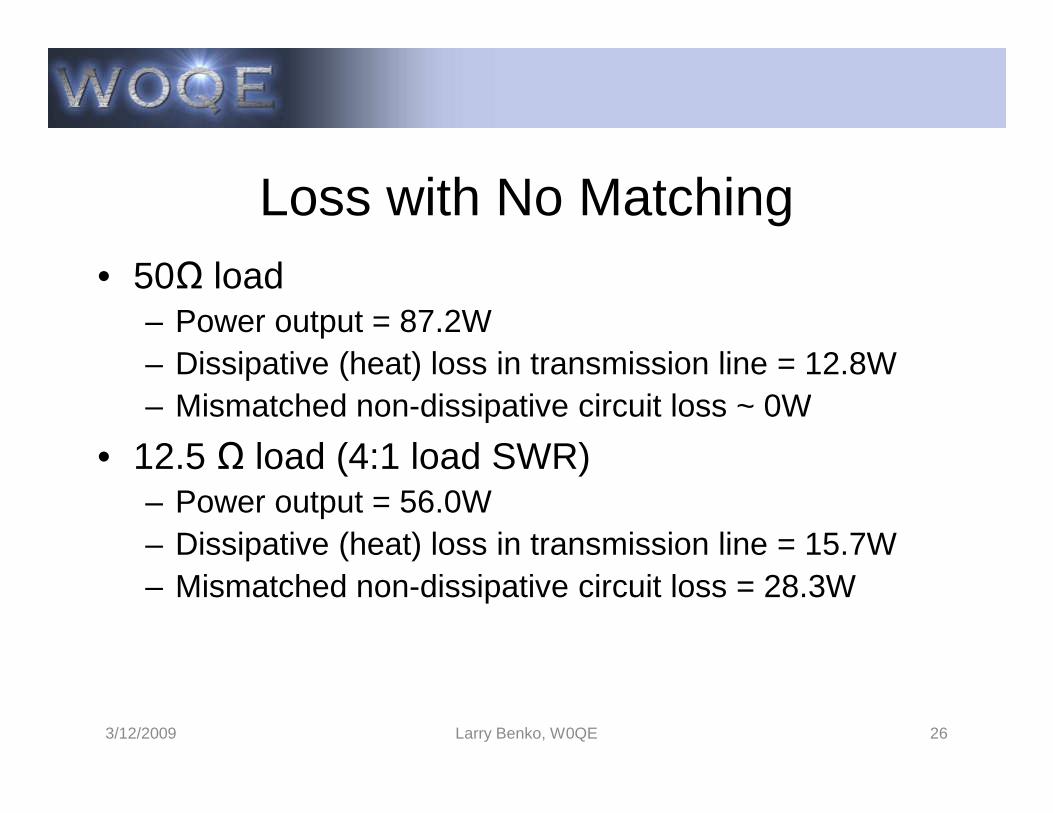
Loss with No Matching• 50Ω load
– Power output = 87.2W– Dissipative (heat) loss in transmission line = 12.8W– Mismatched non-dissipative circuit loss ~ 0W– Mismatched non-dissipative circuit loss ~ 0W
• 12.5 Ω load (4:1 load SWR)– Power output = 56.0W– Dissipative (heat) loss in transmission line = 15.7W– Mismatched non-dissipative circuit loss = 28.3W
3/12/2009 Larry Benko, W0QE 26
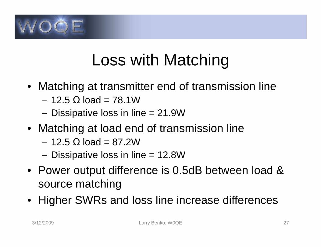
Loss with Matching
• Matching at transmitter end of transmission line– 12.5 Ω load = 78.1W– Dissipative loss in line = 21.9W
• Matching at load end of transmission line• Matching at load end of transmission line– 12.5 Ω load = 87.2W– Dissipative loss in line = 12.8W
• Power output difference is 0.5dB between load & source matching
• Higher SWRs and loss line increase differences
3/12/2009 Larry Benko, W0QE 27

Overall Circuit Loss
• Dissipative loss in the transmission line– Increases with SWR and driving power– Transmission line loss is primarily a function of the
square of the currents summed over length at HFsquare of the currents summed over length at HF
• Non-dissipative loss at source end due to mismatch– Drive with impedance which is the conjugate match to
mismatched line to deliver max. power (antenna tuner)– Reducing the mismatch loss via impedance matching
increases dissipative loss in line
3/12/2009 Larry Benko, W0QE 28

10:1 SWR Example
• 1λ RG-58A (Belden 8259) 46.368’ long @ 14.0MHz connected to a 5 + j0 Ω load with an optional tuner at the antenna, in the shack, or no tuner at all
• Do calculation in both TLW & LTSpice showing consistency in methods
• 0.87dB vs 3.10dB vs 5.68dB (82W vs 49W vs 27W) for a 100W equivalent transmitter not including any SWR power foldback
3/12/2009 Larry Benko, W0QE 29
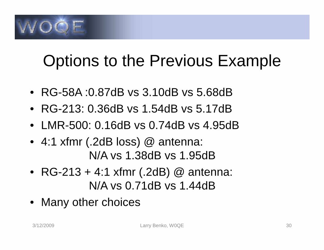
Options to the Previous Example
• RG-58A :0.87dB vs 3.10dB vs 5.68dB • RG-213: 0.36dB vs 1.54dB vs 5.17dB• LMR-500: 0.16dB vs 0.74dB vs 4.95dB• LMR-500: 0.16dB vs 0.74dB vs 4.95dB• 4:1 xfmr (.2dB loss) @ antenna:
N/A vs 1.38dB vs 1.95dB• RG-213 + 4:1 xfmr (.2dB) @ antenna:
N/A vs 0.71dB vs 1.44dB• Many other choices
3/12/2009 Larry Benko, W0QE 30

Measuring Line Zo and Loss
• Measuring surge impedance (Zo)– Open far end of line, measure Z1 @ phase angle A1– Short far end of line, measure Z2 @ phase angle A2– Short far end of line, measure Z2 @ phase angle A2– Zo = square root (Z1 * Z2) @ phase angle (A1 + A2)/2– Usually phase is close to zero
• Measuring Loss– Open far end of line, measure return loss RL1– Short far end of line, measure return loss RL2– Loss = ( RL1 + RL2 )/4
3/12/2009 Larry Benko, W0QE 31
Shielding in Transmission Lines
• At every point currents are equal and out of phase resulting in very little radiation and pickup
• Coaxial transmission line currents are on the • Coaxial transmission line currents are on the outside of the center conductor and inside of shield
• Current on the outside of the coax does affect the currents on the inside very minimally & vice versa
• Currents on the outside of the shield do radiate
3/12/2009 Larry Benko, W0QE 32
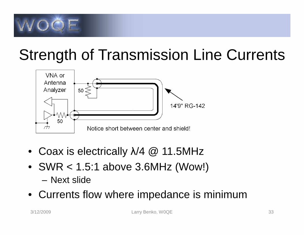
Strength of Transmission Line Currents
• Coax is electrically λ/4 @ 11.5MHz• SWR < 1.5:1 above 3.6MHz (Wow!)
– Next slide
• Currents flow where impedance is minimum 3/12/2009 Larry Benko, W0QE 33
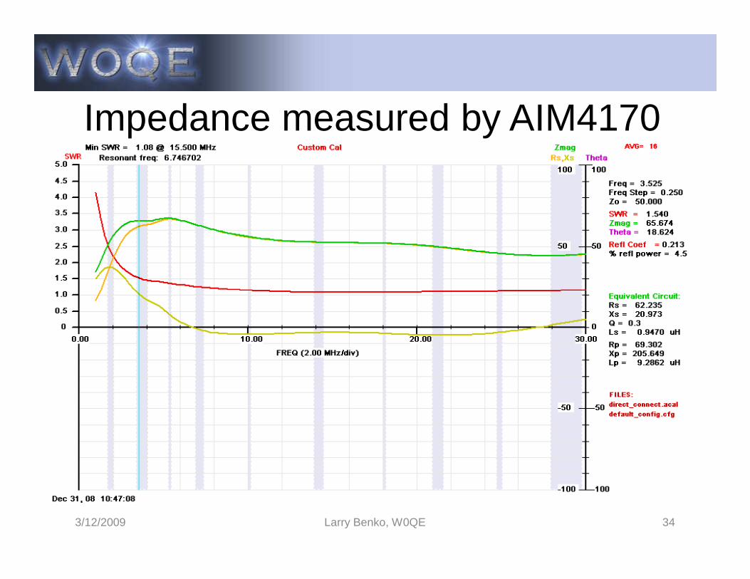
Impedance measured by AIM4170
3/12/2009 Larry Benko, W0QE 34
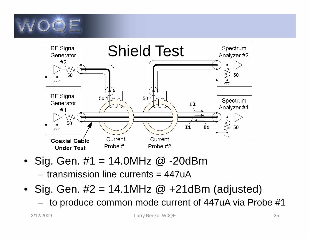
Shield Test
• Sig. Gen. #1 = 14.0MHz @ -20dBm– transmission line currents = 447uA
• Sig. Gen. #2 = 14.1MHz @ +21dBm (adjusted)– to produce common mode current of 447uA via Probe #1
3/12/2009 Larry Benko, W0QE 35
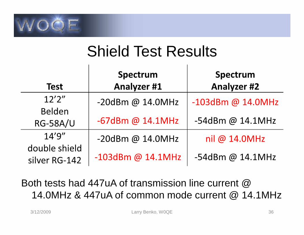
Shield Test Results
TestSpectrum
Analyzer #1Spectrum
Analyzer #212’2”
BeldenRG-58A/U
-20dBm @ 14.0MHz -103dBm @ 14.0MHz-67dBm @ 14.1MHz -54dBm @ 14.1MHz
Both tests had 447uA of transmission line current @ 14.0MHz & 447uA of common mode current @ 14.1MHz
3/12/2009 Larry Benko, W0QE 36
RG-58A/U -67dBm @ 14.1MHz -54dBm @ 14.1MHz14’9”
double shieldsilver RG-142
-20dBm @ 14.0MHz nil @ 14.0MHz-103dBm @ 14.1MHz -54dBm @ 14.1MHz
3 Wire Model for Coax
• Dipoles fed from coax without a balun or non-symmetrical antenna or feed line
• Add simulation wire for the outside of the shield• Add simulation wire for the outside of the shield• Some antenna designs depend on a common
mode current to work as advertised
3/12/2009 Larry Benko, W0QE 37

dB (Decibel)
• Relative measurement, ratio of power or intensity without units
• Used in acoustics, optics, and electronics• Convert to voltages or currents, dB = 10*log10(Po/Pi),
dB = 20*log10(Vo/Vi) if impedance is constant• 2x = 3dB, 4x = 6dB, 8x = 9dB, 10x = 10dB, 5x =7dB,
100x = 20dB, .0001x = -40dB etc.• Absolute dB terms (dBm, dBrnC0, dBW, dBV, dBuV)• Impedance issues, double termination = -3.52dB
3/12/2009 Larry Benko, W0QE 38
Transmission Line Conclusion
• Was presentation too advanced?• Antenna Tuner discussion to follow if any interest
3/12/2009 Larry Benko, W0QE 39
Antenna Tuners and Impedance Matching
3/12/2009 Larry Benko, W0QE 40
Impedance Matching
• Generally increases RF power transfer• Flexible or specific purpose• All impedances can be matched at one frequency• All impedances can be matched at one frequency
– 2 reactive components or 2 pieces of transmission line– Other circuits may match with “nicer” component values
• Matching circuits may provide– Additional harmonic suppression and filtering– Common mode current suppression or balance
• No single circuit is the “best” for all uses
3/12/2009 Larry Benko, W0QE 41

Antenna Tuners
• Impedance matching via adjustable components• Increase RF power transfer to load• Allow transmitters to operate at full power output• Allow transmitters to operate at full power output• Generally do not affect the antenna pattern
unless common mode currents change• Located at transmitter, antenna, or in between• Comprised of high Q low loss components• Cascading tuners need to be done carefully
3/12/2009 Larry Benko, W0QE 42
Antenna Tuner Topologies
• C-L-C high pass, “Tee” tuner• L-C low or high pass, “L” tuner (need to reverse)• Tapped low/medium Q resonant circuit tuner• Tapped low/medium Q resonant circuit tuner• Parallel L-C resonant tapped coil tuner• “L” network with auto-transformer• Single component L or C with mistuned antenna• Transmission line sections and stubs• Balanced versions of the above, static bleed
3/12/2009 Larry Benko, W0QE 43
Smith Chart
• Smith Chart basics– Zo at center, constant SWR = circles– X axis is reflection coefficient (-1 to +1)– Top half is inductive, bottom half is capacitive– Top half is inductive, bottom half is capacitive– Need to think in terms of Z = R +/-jX & Y = G +/-jB
• The Smith Chart allows the user to see graphical solutions to matching problems which enhances the understanding of impedance matching
• Smith Chart could easily be an entire presentation
3/12/2009 Larry Benko, W0QE 44
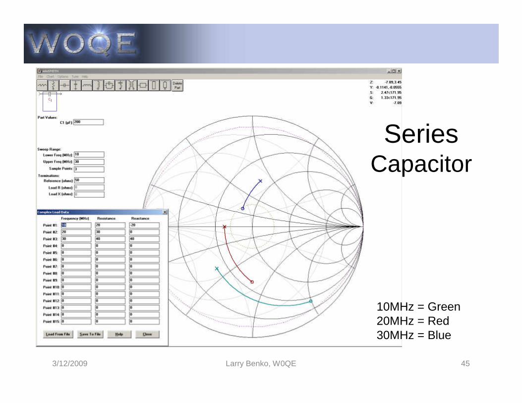
SeriesCapacitor
3/12/2009 Larry Benko, W0QE 45
10MHz = Green20MHz = Red30MHz = Blue
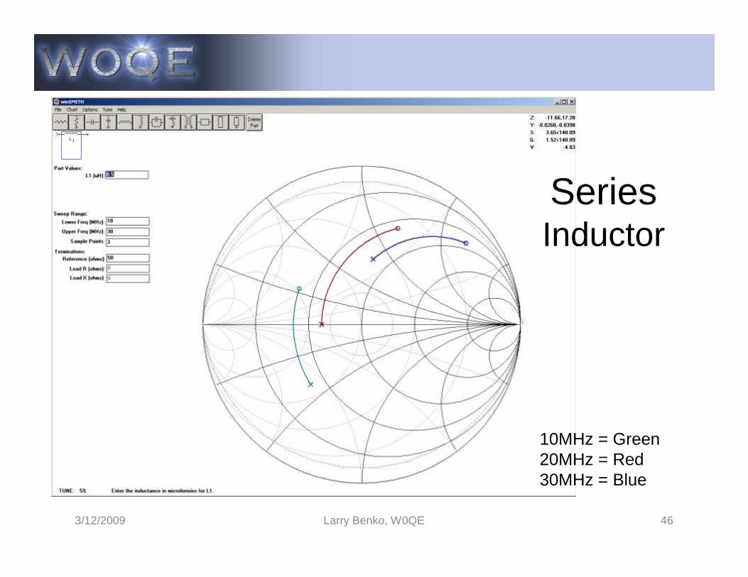
SeriesInductor
3/12/2009 Larry Benko, W0QE 46
10MHz = Green20MHz = Red30MHz = Blue
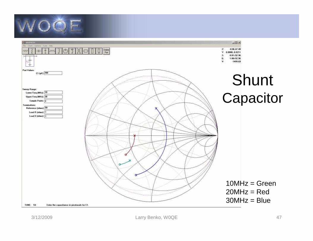
ShuntCapacitor
3/12/2009 Larry Benko, W0QE 47
10MHz = Green20MHz = Red30MHz = Blue

ShuntInductor
3/12/2009 Larry Benko, W0QE 48
10MHz = Green20MHz = Red30MHz = Blue
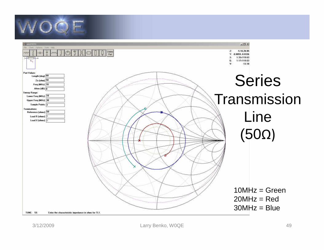
SeriesTransmission
LineΩ)
3/12/2009 Larry Benko, W0QE 49
(50Ω)
10MHz = Green20MHz = Red30MHz = Blue
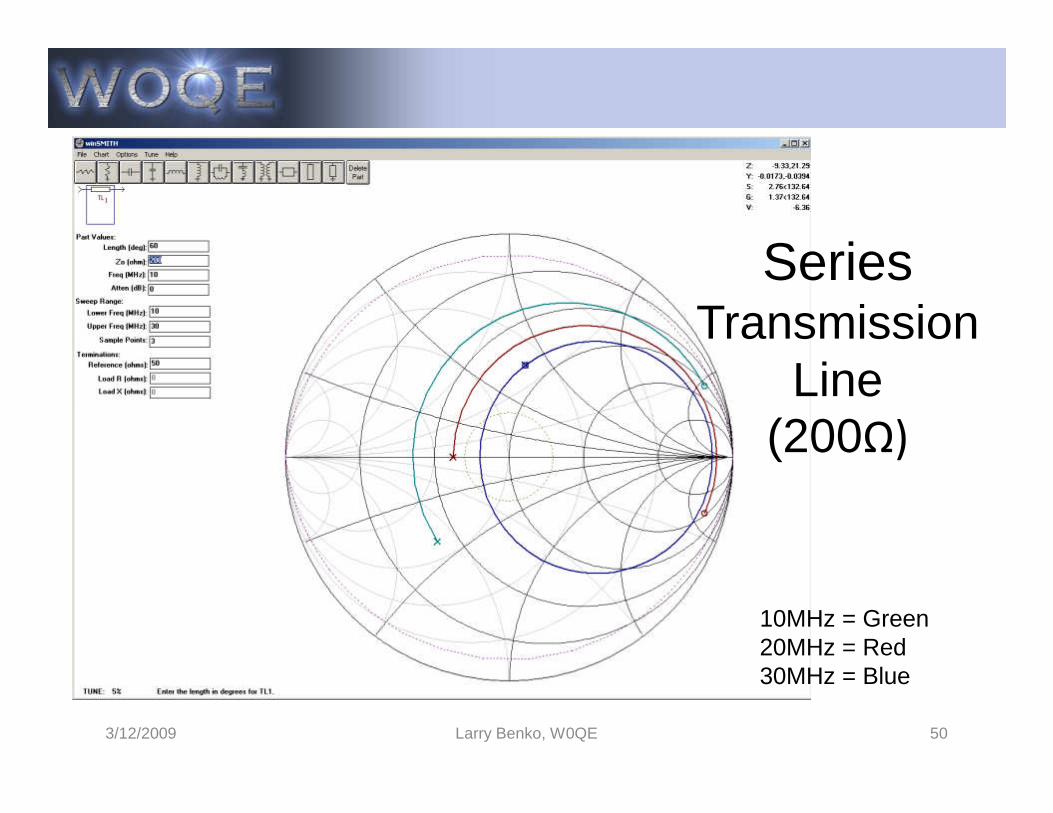
SeriesTransmission
LineΩ)
3/12/2009 Larry Benko, W0QE 50
(200Ω)
10MHz = Green20MHz = Red30MHz = Blue
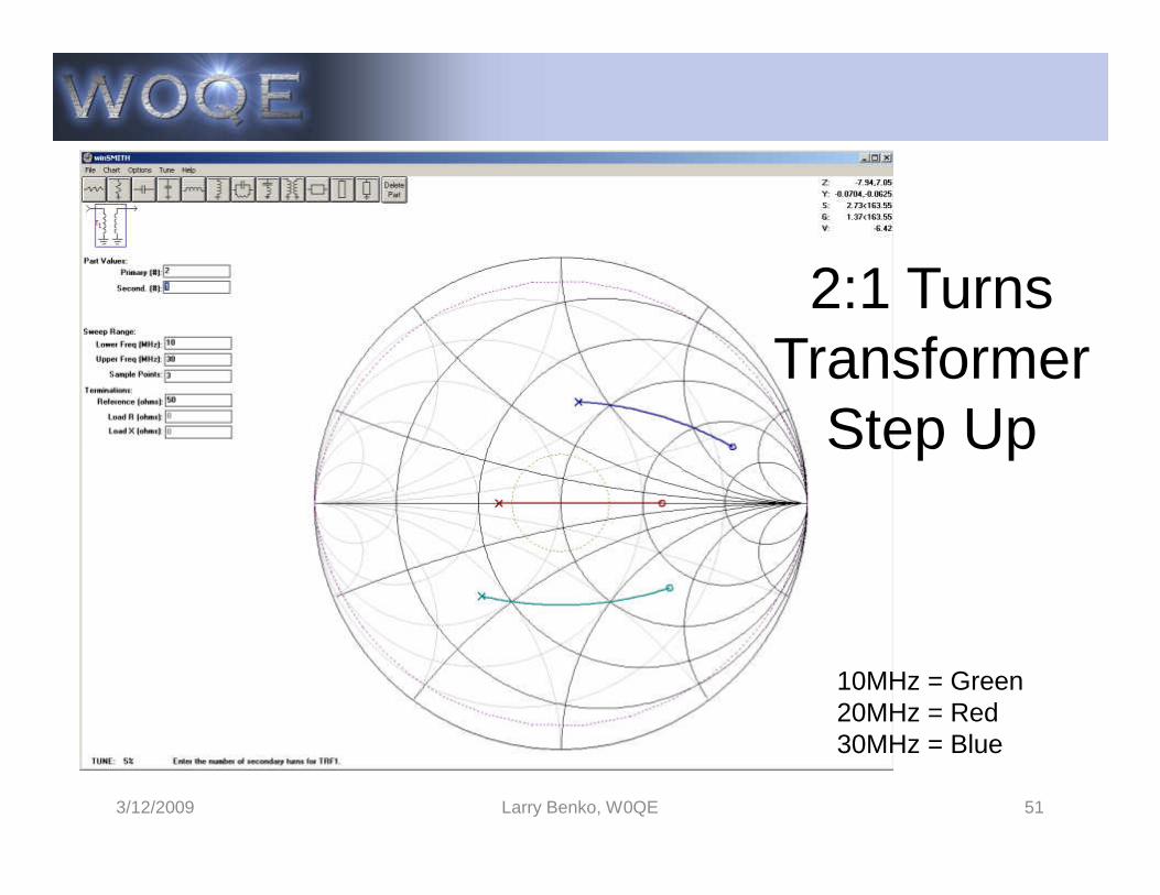
2:1 TurnsTransformer
Step Up
3/12/2009 Larry Benko, W0QE 51
Step Up
10MHz = Green20MHz = Red30MHz = Blue
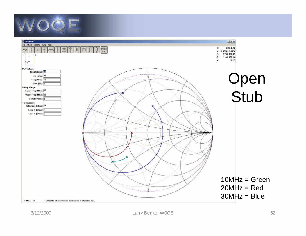
OpenStub
3/12/2009 Larry Benko, W0QE 52
10MHz = Green20MHz = Red30MHz = Blue
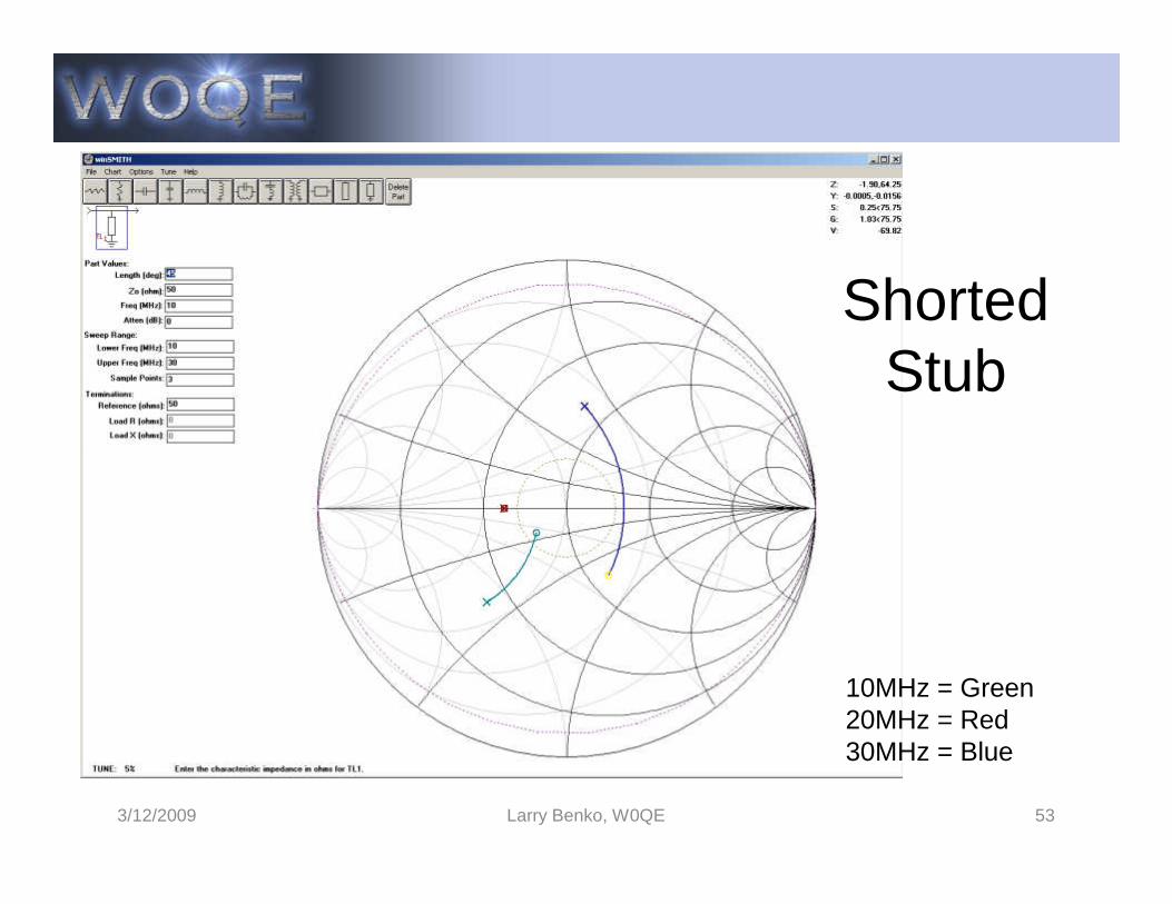
ShortedStub
3/12/2009 Larry Benko, W0QE 53
10MHz = Green20MHz = Red30MHz = Blue
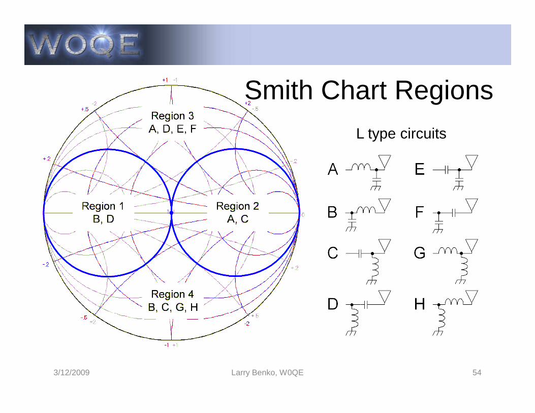
Smith Chart Regions
L type circuits
3/12/2009 Larry Benko, W0QE 54
Effect of Transmission Lines
• Series lengths of lossless transmission lines (Zo) trace clockwise circles geometrically centered at Zo
• 180 electrical degrees of line = 1 revolution• 180 electrical degrees of line = 1 revolution• Loss in line causes circle to become a spiral to Zo• Shunt lengths of shorted or open transmission line
look like shunt L & C components with medium Q• The reactance in a non-resonant antenna can be
used as part of the matching network
3/12/2009 Larry Benko, W0QE 55
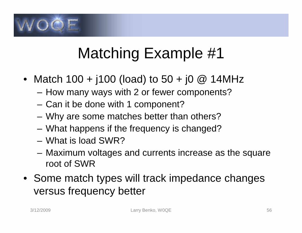
Matching Example #1
• Match 100 + j100 (load) to 50 + j0 @ 14MHz– How many ways with 2 or fewer components?– Can it be done with 1 component?– Why are some matches better than others?– Why are some matches better than others?– What happens if the frequency is changed?– What is load SWR?– Maximum voltages and currents increase as the square
root of SWR
• Some match types will track impedance changes versus frequency better
3/12/2009 Larry Benko, W0QE 56
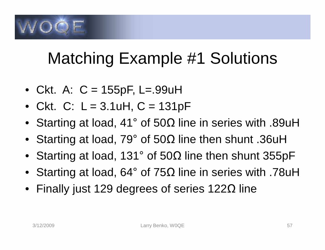
Matching Example #1 Solutions
• Ckt. A: C = 155pF, L=.99uH• Ckt. C: L = 3.1uH, C = 131pF• Starting at load, 41° of 50Ω line in series with .89uH• Starting at load, 41° of 50Ω line in series with .89uH• Starting at load, 79° of 50Ω line then shunt .36uH• Starting at load, 131° of 50Ω line then shunt 355pF• Starting at load, 64° of 75Ω line in series with .78uH• Finally just 129 degrees of series 122Ω line
3/12/2009 Larry Benko, W0QE 57
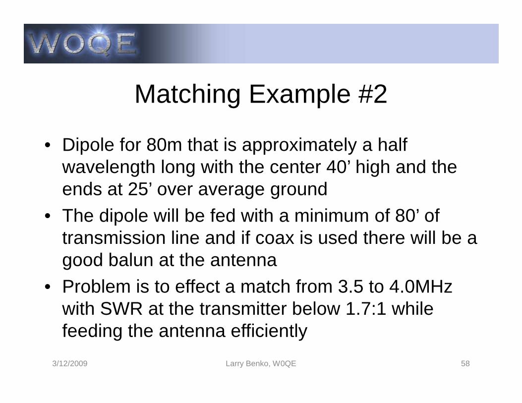
Matching Example #2
• Dipole for 80m that is approximately a half wavelength long with the center 40’ high and the ends at 25’ over average ground
• The dipole will be fed with a minimum of 80’ of transmission line and if coax is used there will be a good balun at the antenna
• Problem is to effect a match from 3.5 to 4.0MHz with SWR at the transmitter below 1.7:1 while feeding the antenna efficiently
3/12/2009 Larry Benko, W0QE 58

Dipole Feed Point Impedance
3/12/2009 Larry Benko, W0QE 59
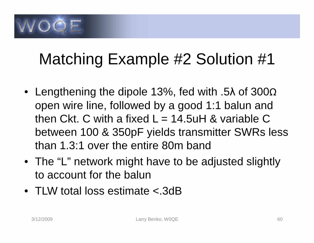
Matching Example #2 Solution #1
• Lengthening the dipole 13%, fed with .5λ of 300Ωopen wire line, followed by a good 1:1 balun and then Ckt. C with a fixed L = 14.5uH & variable C then Ckt. C with a fixed L = 14.5uH & variable C between 100 & 350pF yields transmitter SWRs less than 1.3:1 over the entire 80m band
• The “L” network might have to be adjusted slightly to account for the balun
• TLW total loss estimate <.3dB
3/12/2009 Larry Benko, W0QE 60
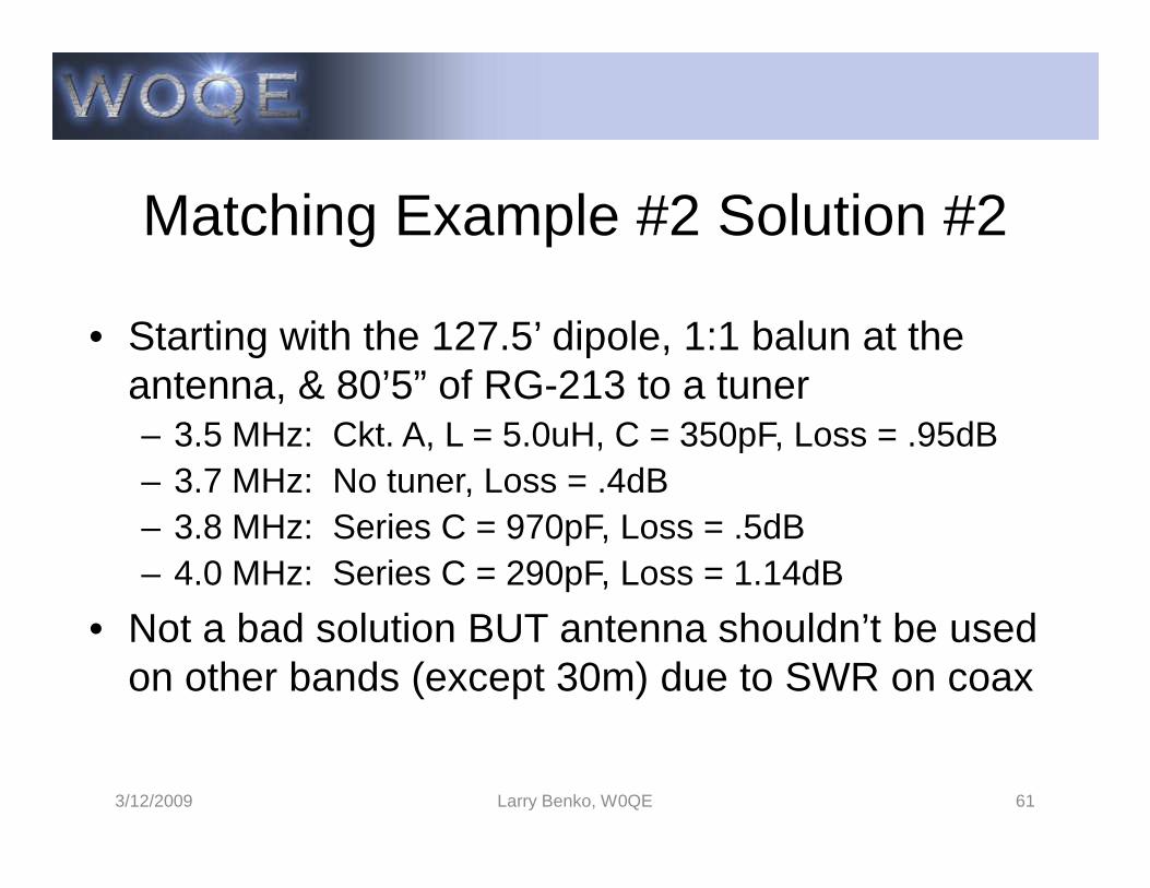
Matching Example #2 Solution #2
• Starting with the 127.5’ dipole, 1:1 balun at the antenna, & 80’5” of RG-213 to a tuner– 3.5 MHz: Ckt. A, L = 5.0uH, C = 350pF, Loss = .95dB– 3.5 MHz: Ckt. A, L = 5.0uH, C = 350pF, Loss = .95dB– 3.7 MHz: No tuner, Loss = .4dB– 3.8 MHz: Series C = 970pF, Loss = .5dB– 4.0 MHz: Series C = 290pF, Loss = 1.14dB
• Not a bad solution BUT antenna shouldn’t be used on other bands (except 30m) due to SWR on coax
3/12/2009 Larry Benko, W0QE 61

Matching Example #2 Continued
• There are many other solutions and some may be better than the 2 previous ones
• Building open wire line of Zo between 150Ω and • Building open wire line of Zo between 150Ω and 700Ω is easy and 4 wire line is good for lower impedances with better balance
• Coax can be paralleled for lower impedances
3/12/2009 Larry Benko, W0QE 62
Final Matching Example
• 160m dipole 150’ high sloping down at ~25 degrees• Resonant at 1.86 MHz and want to cover entire
160m band160m band• Matching to be done at the transmitter• Impedance measured through 160m high pass 9
pole filter due to AM broadcast interference of +30dBm after effects of filter were calibrated out
3/12/2009 Larry Benko, W0QE 63
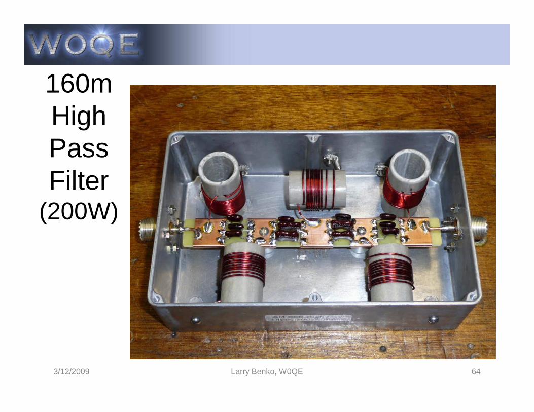
160mHighPassFilter
(200W)(200W)
3/12/2009 Larry Benko, W0QE 64

160m Dipole Measured in Shack
2.0 MHz5.97:1 SWR
1.8 MHz3.66:1 SWR
3/12/2009 Larry Benko, W0QE 65
1.86 MHz1.76:1 SWR

No AdjustmentMatch
No adjustments, SWR<1.7:1
3/12/2009 Larry Benko, W0QE 66
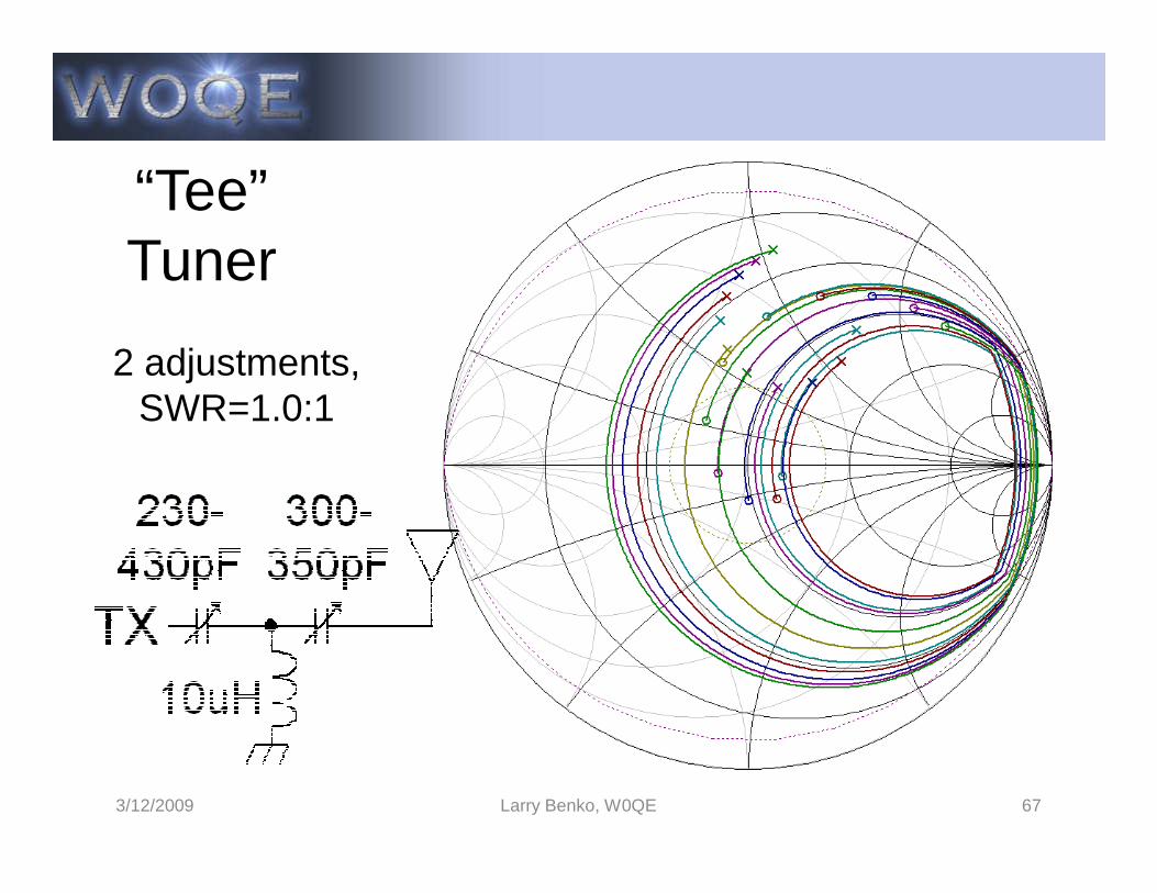
“Tee”Tuner
2 adjustments, SWR=1.0:1
3/12/2009 Larry Benko, W0QE 67
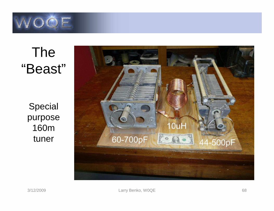
The“Beast”
Special
3/12/2009 Larry Benko, W0QE 68
Special purpose
160m tuner
Antenna Tuners and Impedance Matching Conclusion
• Is anyone still awake?• We could do more examples • Topics for the future?
Tuning without generating QRMOther ideas?
3/12/2009 Larry Benko, W0QE 69


