157
Transmission Media 1

Transmission Media
1

Content Transmission Media
Guided Media:
Twisted Pair UTP STP Co-Axial Cable Fibre Optic Cable
Propagartion Modes Transmission Impairment
Unguided Media: Propagation Methods Radio Waves Antenna Microwaves Infrared
4

What is Tranmission Media ?
In data communication,
• Transmission media is a pathway that carries the
information from sender to receiver.
• We use different types of cables or waves to
transmit data.
• Data is transmitted normally through electrical or
electromagnetic signals.
5

Description• Transmission media are located below the physical
layer
• Computers use signals to represent data.
• Signals are transmitted in form of electromagnetic energy.
6

Classification of Transmission media
7
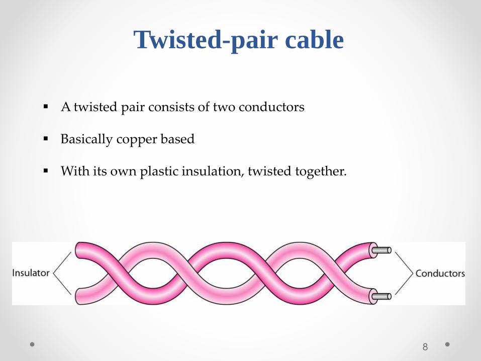
Twisted-pair cable
A twisted pair consists of two conductors
Basically copper based
With its own plastic insulation, twisted together.
8

Twisted Pair Description• Provide protection against cross talk or
interference(noise)
• One wire use to carry signals to the receiver
• Second wire used as a ground reference
• For twisting, after receiving the signal remains same.
• Therefore number of twists per unit length, determines the quality of cable.
9

Twisted Pair
Advantages:
• Cheap
• Easy to work with
Disadvantages:
• Low data rate
• Short range
10

Twisted Pair - Applications
• Very common medium
• Can be use in telephone network
• Connection Within the buildings
• For local area networks (LAN)
11

Twisted Pair Cables
Twisted Pair cables
Unshielded
Twisted Pair
(UTP)
Shielded
Twisted pair
(STP)
12
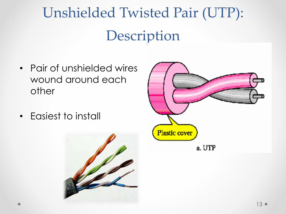
Unshielded Twisted Pair (UTP):
Description
• Pair of unshielded wires
wound around each
other
• Easiest to install
13

ApplicationsUTP :
Telephone subscribers connect to the central telephone office
DSL lines
LAN – 10Mbps or 100Mbps
14

UTP Cable Types
Cat 7
Cat 6
Cat 5e
Cat 5
Cat 4
Cat 3
Cat 2
Cat 1
UTP
Cat means category according to IEEE standards. IEEE is de jure standard
15
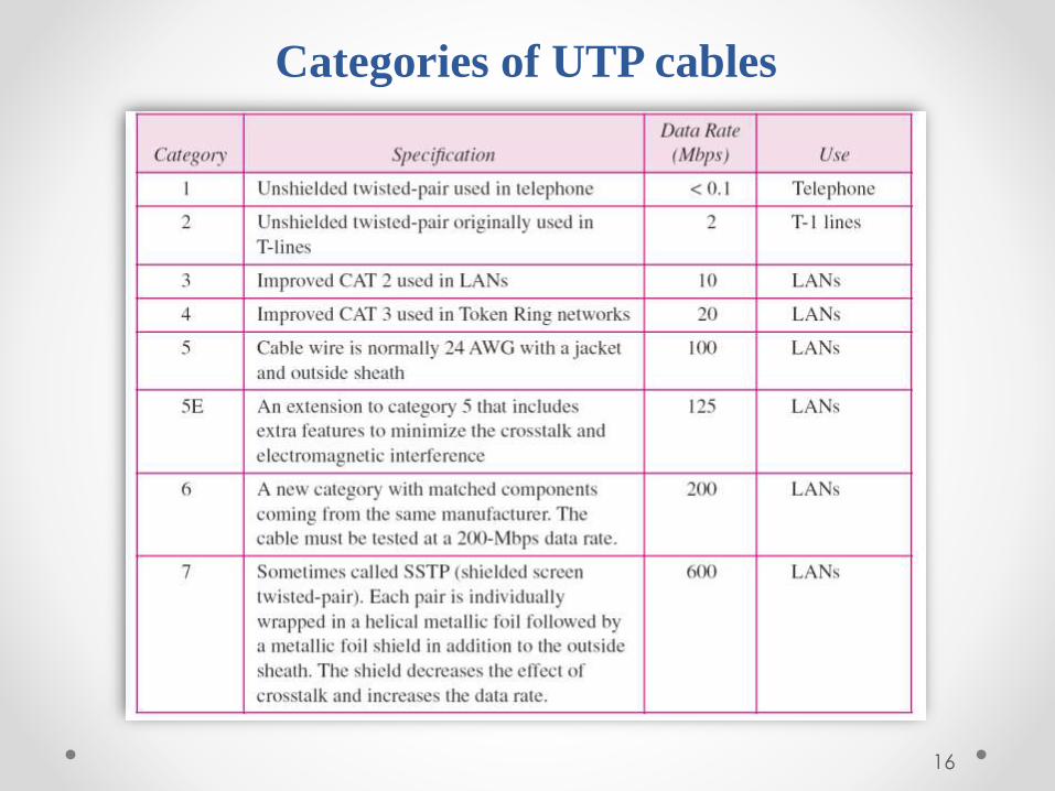
Categories of UTP cables
16

UTP connector and Tools
RJ45 (RJ stands for registered jack) is a keyed connector, it means that it can be inserted in only one way
17
Crimper Tool

Advantages of UTP:
Affordable
Most compatible cabling
Major networking system
Disadvantages of UTP:
• Suffers from external Electromagnetic interference
18
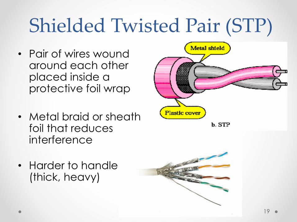
Shielded Twisted Pair (STP)
• Pair of wires wound around each other placed inside a protective foil wrap
• Metal braid or sheath foil that reduces interference
• Harder to handle (thick, heavy)
19

STP Application
• STP is used in IBM token ring networks.
• Higher transmission rates over longer distances.
20

Advantages of STP:
Shielded
Faster than UTP
Disadvantages of STP:
More expensive than UTP
High attenuation rate
21

Co-axial cable carries signal of higher frequency ranges than twisted pair cable
Co-axial Cable
• Inner conductor is a solid wire
• Outer conductor serves as a shield against noise and a second
conductor
22

Categories of coaxial cables
Coaxial cables are categorized by Radio Government (RG) ratings, RG is De Jure standards
23

BNC Connectors – Bayone Neil Concelman
Coaxial Cable Connectors
To connect coaxial cable to devices we need coaxial connectors
BNC Connector is used at the end of the cable to a deviceExample: TV set conenction
BNC T connector used to Ethernet networks to branch out connection to computer or other devices
BNC terminator is used at the end of the cable to prevent the reflection of the signal
24

Coaxial Cable Applications
• Most versatile medium
• Television distribution
• Long distance telephone transmission
• Can carry 10,000 voice calls simultaneously
• Short distance computer systems links
• Local area networks
25

ADVANTAGES
Easy to wire
Easy to expand
Moderate level of Electro Magnetic Interference
DISADVANTAGE
Single cable failure can take down an entire network
Cost of installation of a coaxial cable is high due to its thickness and stiffness
Cost of maintenance is also high
COAXIAL CABLE
26
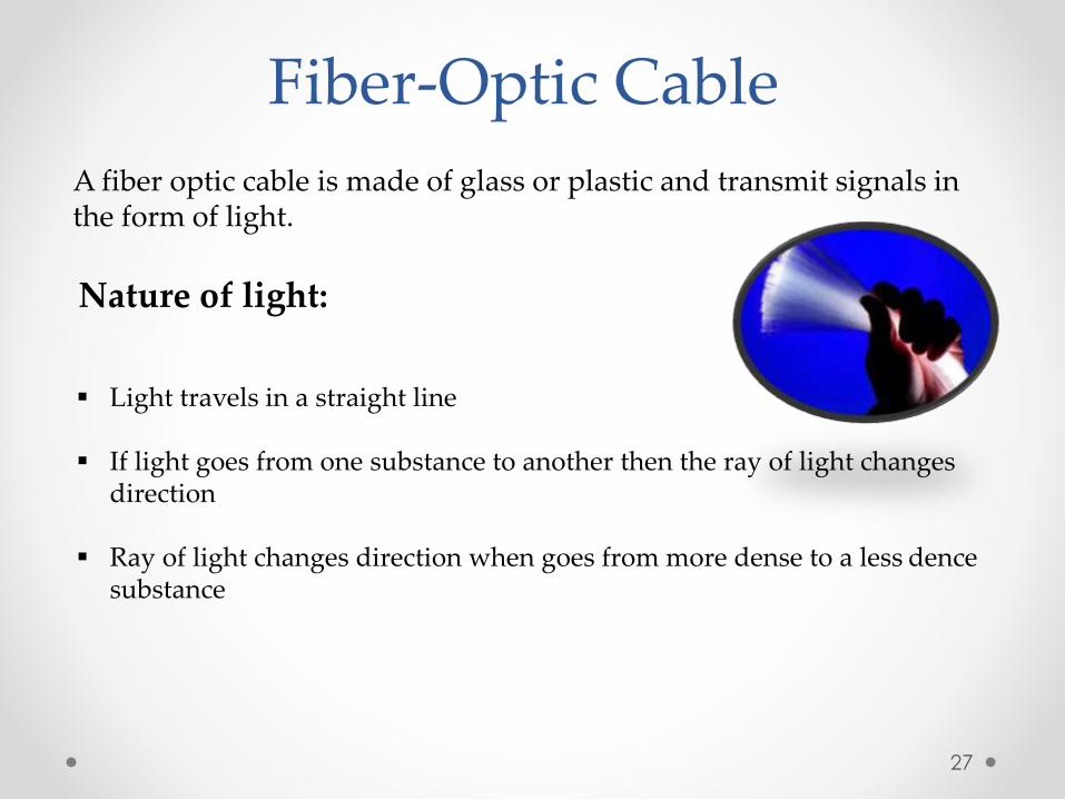
Fiber-Optic Cable
A fiber optic cable is made of glass or plastic and transmit signals in the form of light.
Nature of light:
Light travels in a straight line
If light goes from one substance to another then the ray of light changes direction
Ray of light changes direction when goes from more dense to a less dencesubstance
27

Bending of light ray• Angle of Incidence (I): the angle the ray makes with the line
perpendicular to the interface between the two substances
• Critical Angle: the angle of incidence which provides an angle of refraction of 90-degrees.
28
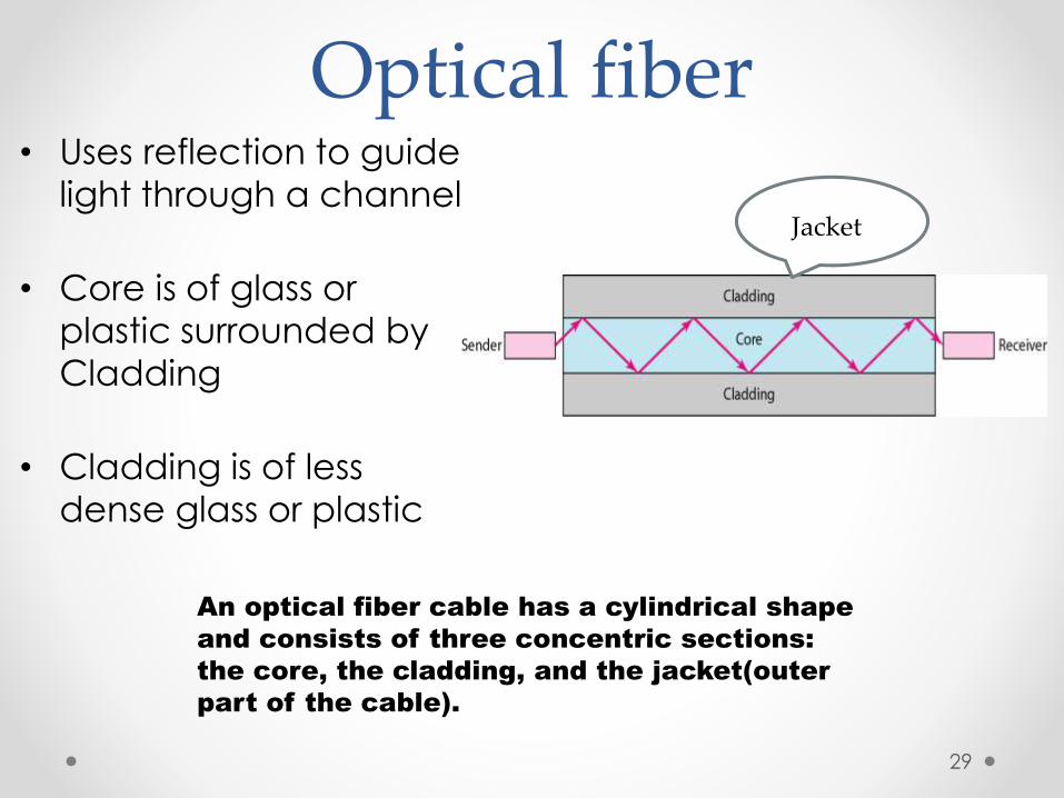
Optical fiber• Uses reflection to guide
light through a channel
• Core is of glass or
plastic surrounded by
Cladding
• Cladding is of less
dense glass or plastic
An optical fiber cable has a cylindrical shape
and consists of three concentric sections:
the core, the cladding, and the jacket(outer
part of the cable).
Jacket
29
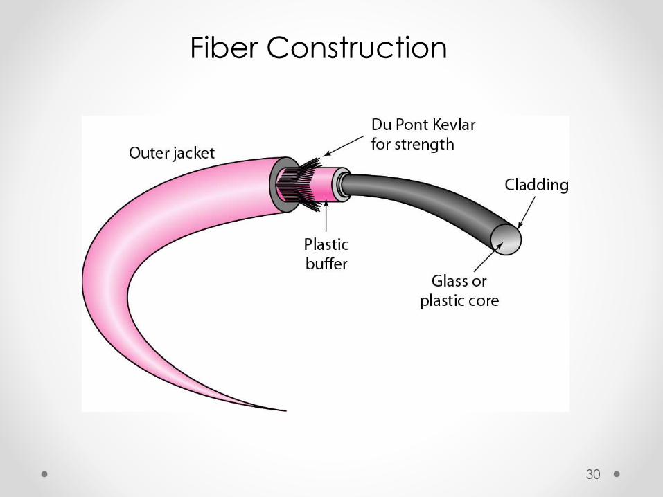
Fiber Construction
30

Fiber – Optic cable Connectors
31
Subscriber Channel (SC) Connecter
Straight-Tip (ST) ConnecterSame szie as RJ45 connector

Areas of Application
Telecommunications
Local Area Networks
Cable TV
CCTV
Medical Education
32

Optical Fiber Advantages
Greater capacityExample: Data rates at 100 Gbps
Smaller size & light weight
Lower attenuation
Electromagnetic isolation
More resistance to corrosive materials
Greater repeater spacing facilityExample: After every 10s of km at least
33

Optical Fiber Disadvantages
• Installation and maintenance need expertise
• Only Unidirectional light propagation
• Much more expensive
34

Propagation Modes
Propagation Modes
Multimode Single Mode
Step -Index Graded - Index
35
When signal goes from one point to another there are need for propagation modes.

Propagation Modes
36

Transmission Impairment
• The Imperfection in transmission media causes
signal impairment
• What is sent is not what is received
due to impairment
• Three causes of impairement are
1)Attenuation,
2)Distortion
3)Noise
ATTENUATION
DISTORTION
NOISE
37

• Attenuation means a loss of energy.
• Distortion means that the signal changes its form or
shape.
• Noise is another cause of impairement.
• Several types of noise
Example: thermal noise, induced noise, crosstalk
Transmission Impairment
38

Unguided Media: Wireless Transmission
3 kHz 300GHz 400THz 900THz
Radio wave & Micro wave Infrared
Electro magnetic spectrum for wireless communication:
Unguided media transport electromagnetic waves without using a physical conductor it is known as wireless communication.
Signals broadcast through free space and available to capable receiver
39

Propagation methods
Unguided signals travels from the source to destination in several ways it is known as propagation.
They are three types: Ground propagation Sky propagation Line-of-Sight Propagation
40

Ground propagation:
Radio waves travel through the lowest portion of the atmosphere
Touching the earth.
Sky propagation:
Radio waves radiate to the ionosphere then they are reflected back to earth.
Line-of-Sight Propagation:
In straight lines directly from antenna to antenna.
41

Bands using propagation method
Band Range Propagation Application
VLF 3–30 KHz Ground Long-range radio navigation
LF 30–300 KHz GroundRadio beacons and
navigational locators
MF 300 KHz–3 MHz Sky AM radio
HF 3–30 MHz SkyCitizens band (CB),
ship/aircraft communication
VHF 30–300 MHzSky and
line-of-sight
VHF TV,
FM radio
UHF 300 MHz–3 GHz Line-of-sightUHF TV, cellular phones,
paging, satellite
SHF 3–30 GHz Line-of-sight Satellite communication
EHF 30–300 GHz Line-of-sight Long-range radio navigation
42

Unguided Media
Wireless transmission waves
43

Omnidirectional Antenna
Frequencies between 3
KHz and 1 GHz.
Used for
multicasts(multiple way)
communications, such as
radio and television, and
paging system.
Radio waves can
penetrate buildings easily,
so that widely use for
indoors & outdoors
communication.
Unguided Media – Radio Waves
44

An Antenna is a structure that is generally a metallic object may be a wire or group of wires, used to convert high frequency current into electromagnetic waves.
Antenna are two types:
• Transmission antenna
Transmit radio frequency from transmitter
Radio frequency thenConvert to electromagnetic energy by antenna
Then, radiate into surrounding environment
• Reception antenna
Electromagnetic energy get in antenna
Then Antenna convert radio frequency to electrical energy
Then, Goes to receiver
same antenna can be used for both purposes
Antennas
45
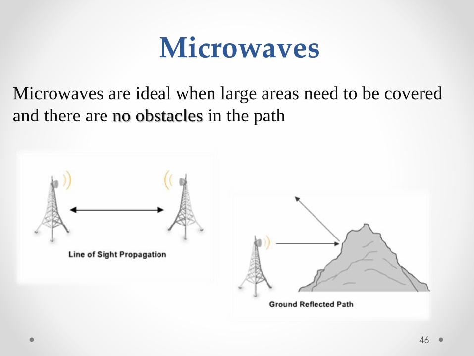
Microwaves are ideal when large areas need to be covered
and there are no obstacles in the path
46
Microwaves

Micro waves Transmission• Microwaves are unidirectional
• Micro waves electromagnetic waves having frequency between
1 GHZ and 300 GHZ.
• There are two types of micro waves data communication system
: terrestrial and satellite
• Micro waves are widely used for one to one communication
between sender and receiver,
example: cellular phone, satellite networks and in wireless
LANs(wifi), WiMAX,GPS
47
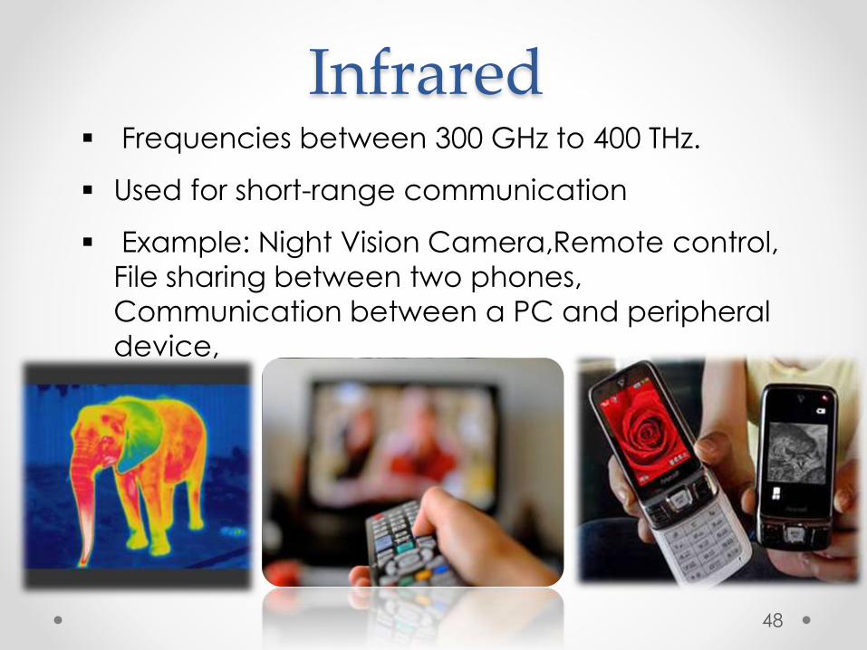
Infrared Frequencies between 300 GHz to 400 THz.
Used for short-range communication
Example: Night Vision Camera,Remote control,
File sharing between two phones,
Communication between a PC and peripheral
device,
48

1.1 Computer Networks

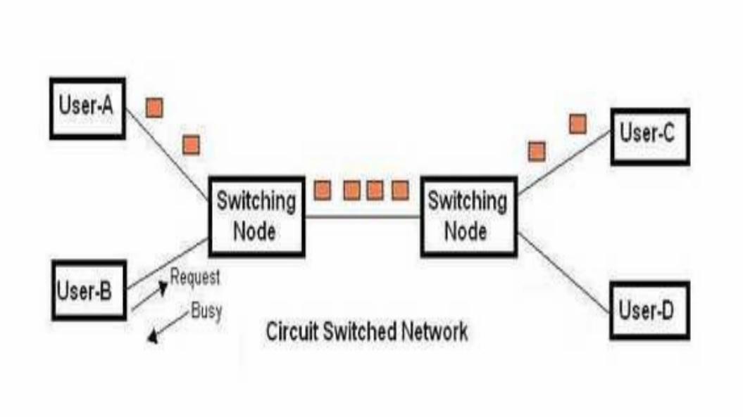
Circuit Switching

Circuit SwitchingEstablishes a dedicated physical path between the sender and receiver of the message before a message is delivered
The entire message travels through the established path from sender to the receiver
Received Message is Acknowledged by Receiver
Same as Telephone Communication

Pros of Circuit Switching
a)Dedicated path/circuit provides guaranteed data delivery
b)is suitable for long continuous transmission.
c)Uses Connection Oriented Services

Cons of Circuit Switching
a) Waste of bandwidth if its Idle.
b) Require more bandwidth.
c) Time Required to establish a link is too long

Packet Switching

Packet Switchingdoesn’t establish any physical connection before the transmission starts
Message is divided into Packets and routed Independently
Uses Connection Less Services


Pros of Packet Switchinga) High Data Transmission
b) No time Lost for Establishing Link
c) Faster
d) Independent Travel

Cons of Packet Switchinga) Packets May Lost their Routes
b) Wrong Order of Packets
c) Large Amount of Resources needed to handle Packets

Circuit Switchingvs
Packet Switching

Circuit Switching Packet Switching
Connection Oriented Connection Less
Entire Message Have to follow same route during transmission
Entire Message can be divided and routed Independently
Implemented at Physical Layer Implemented at Network Layer
Waste of bandwidth if Idle No Waste of bandwidth if Idle
Initially designed for Voice Transmission
Initially designed for Data Transmission

Virtual Circuits Networks

Virtual Circuit NetworksIs a packet switching methodology but establishes Link before communication
Entire Message must have to follow same Link to destination
is connection orientated
Virtual circuit is cleared after the data transfer is completed

Pros of Virtual Circuits Networks
a) Uses Connection Oriented Services
b) Can use Diferent Physical Links each time

Cons of Virtual Circuits Networks
a) Link Setup Time
b) Resilience to the loss of a trunk i.e. no dynamic switching in case of link failure

Datagram Networks

Datagram Networks
Is a packet switching methodology but no any Dedicated Link
Message have to divided into Datagrams and Each Packets are treated Independently
Connection Less

Pros of Datagram Networks
a) It is connectionless service
b) Every datagrams are treated Independently
c) Faster

Cons of Datagram Networks
a) Not Reliable
b)Packet May lost and no Service for Retransmission
c) Need of High Resources

Possible Questions
a) Explain about Circuit Switching with Pros and Cons
b) Explain about Packet Switching with Pros and Cons
c) Explain about Virtual Circuit Networks with Pros and Cons
d) Explain about Datagram Networks with Pros and Cons
e) Compare Circuit Switching and Packet Switching
f) How Virtual Circuit Networks are difer from Circuit Switching
g) Compare Virtual Circuit Networks with Datagram Networks.

Data CommunicationData Communication & &
Computer NetworksComputer Networks
MSA Technosoft

Data Communications
The term telecommunication means communication at a distance. The word data refers to information presented in whatever form is agreed upon by the parties creating and using the data. Data communications are the exchange of data between two devices via some form of transmission medium such as a wire cable.

Five Components of Data Five Components of Data CommunicationCommunication

Five Components of Data CommunicationMessage:
text, number, images, audio, and videoSender and Receiver
devices that send/receive data message Computer, workstation, telephone, TV, etc.
Transmission medium Physical path thru which the message travels
Protocol Set of rules governing data communications

Data flow (simplex, half-duplex, and full-duplex)
NETWORKS
A network is a set of devices (often referred to as nodes) connected by communication links. A node can be a computer, printer, or any other device capable of sending and/or receiving data generated by other nodes on the network.
Network Criteria
Performance Mostly measured by throughput and delay
Reliability The frequency of failure Recovery time from a failure
Security Protecting data from
unauthorized accessDamage

Type of ConnectionPoint-to-PointMultipoint (multi-drop)

Physical TopologyMesh topologyStar topologyBus topologyRing topologyHybrid topology

Network Topologies
LAN topologiesWAN topologies

LAN topologiesPhysical
Describes the geometric arrangement of components that make up the LAN
Logical Describes the possible connections
between pairs of networked end-points that can communicate

LAN Topologies(Physical) Bus Star Ring Switched Daisy chains Hierarchies

Bus topologyAll networked nodes are
interconnected, peer to peer, using a single, open-ended cable
Both ends of the bus must be terminated with a terminating resistor to prevent signal bounce

Bus topology

Advantages of Bus topology Easy to implement and extend Well suited for temporary networks
that must be set up in a hurry Typically the least cheapest topology
to implement Failure of one station does not affect
others
Disadvantages of Bus topology
Difficult to administer/troubleshoot Limited cable length and number of
stations A cable break can disable the entire
network; no redundancy Maintenance costs may be higher in the
long run Performance degrades as additional
computers are added

Ring topologystarted out as a simple peer-to-peer
LAN topologyEach networked workstation had two
connections: one to each of its nearest neighbors
Data was transmitted unidirectionally around the ring
Sending and receiving of data takes place by the help of TOKEN

Token PassingToken contains a piece of information
which along with data is sent by the source computer
This token then passes to next node, which checks if the signal is intended to it If yes, it receives it and passes the empty
to into the network otherwise passes token along with the data
to next node

Ring topology

Advantages of Ring topology This type of network topology is very
organized Performance is better than that of Bus
topology No need for network server to control the
connectivity between workstations Additional components do not affect the
performance of network Each computer has equal access to
resources

Disadvantages of Ring topology Each packet of data must pass
through all the computers between source and destination, slower than star topology
If one workstation or port goes down, the entire network gets affected
Network is highly dependent on the wire which connects different components
Star topologyHave connections to networked devices
that “radiate” out form a common pointEach networked device in star topology
can access the media independentlyHave become the dominant topology
type in contemporary LANsStars have made buses and rings
obsolete in LAN topologies

Star topology
Advantages of star topology
Compared to Bus topology it gives far much better performance
Easy to connect new nodes or devices Centralized management. It helps in
monitoring the network Failure of one node or link doesn’t
affect the rest of network

Disadvantages of star topology
If central device fails whole network goes down
The use of hub, a router or a switch as central device increases the overall cost of the network
Performance and as well number of nodes which can be added in such topology is depended on capacity of central device

Switched topology
A switch is a multiport, Data Link Layer deviceA switch “learns” Media Access Control addresses
and stores them in an internal lookup tableTemporary, switched paths are created between the
frame’s originator and its intended recipient, and the frames are forwarded along the temporary path
Switched topology features multiple connections to a switching hub/Switch
Each port, and the device to which it connects, has its own dedicated bandwidth

Switched topology
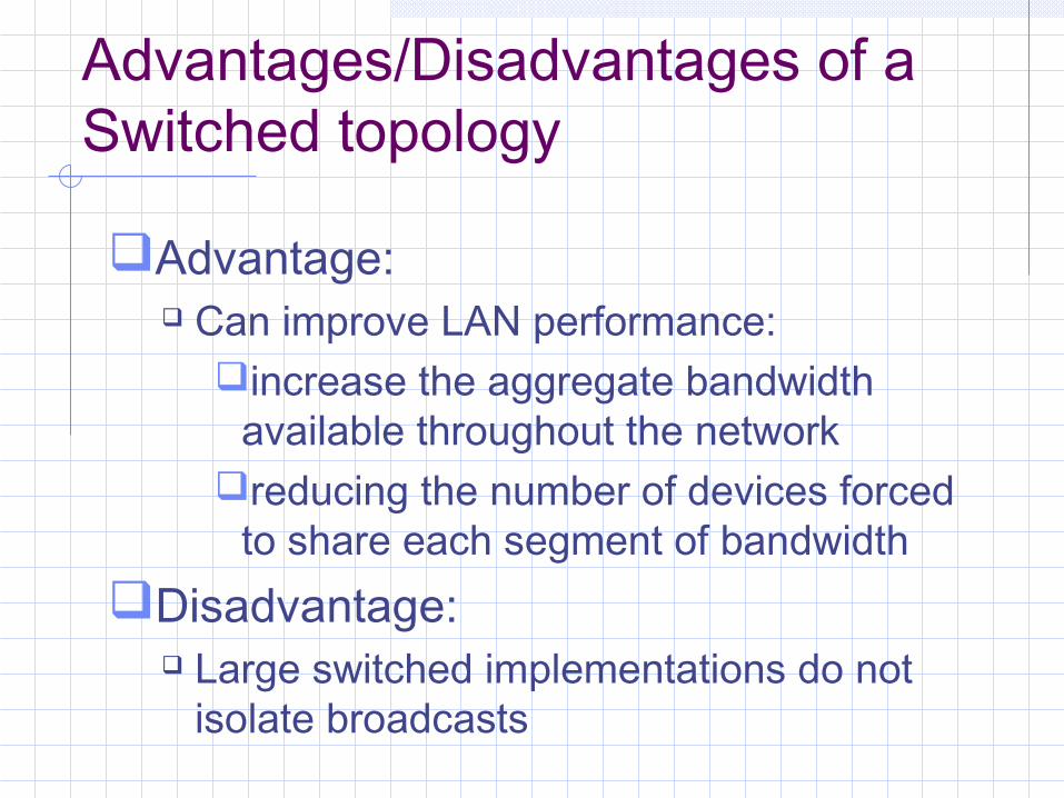
Advantages/Disadvantages of a Switched topology
Advantage: Can improve LAN performance:
increase the aggregate bandwidth available throughout the network
reducing the number of devices forced to share each segment of bandwidth
Disadvantage: Large switched implementations do not
isolate broadcasts

Daisy chainsDeveloped by serially interconnecting all
the hubs of a networkThis simple approach uses ports on
existing hubs for interconnecting the hubsDaisy chains are easily built and don’t
require any special administrative skillsDaisy chains were, historically, the
interconnection method of choice for emerging, first-generation LANs

Daisy chains

Disadvantage of Daisy chainIncreases the number of connections,
and therefore the number of devices, on a LAN. Too many devices competing for the same amount of bandwidth can create collisions and quickly incapacitate a LAN
HierarchiesHierarchical topologies consist of more
than one layer of hubs. Each layer serves a different network function
The bottom tier is reserved for user station and server connectivity. Higher-level tiers provide aggregation of the user-level tier
A hierarchical arrangement is best suited for medium-to-large-sized LANs that must be concerned with scalability of the network and with traffic aggregation

Hierarchical ringsRing networks can be scaled up by
interconnecting multiple rings in a hierarchical fashion
User station and server connectivity can be provided by as many limited size rings as are necessary to provide the required level of performance
A second-tier ring, either Token Ring or FDDI, can be used to interconnect all the user level rings and to provide aggregated access to the Wide Area Network (WAN)

Hierarchical rings

Hierarchical starsStar topologies, can be implemented in
hierarchical arrangements of multiple stars
Hierarchical stars can be implemented as a single collision domain or segmented into multiple collision domains using switches, routers or bridges
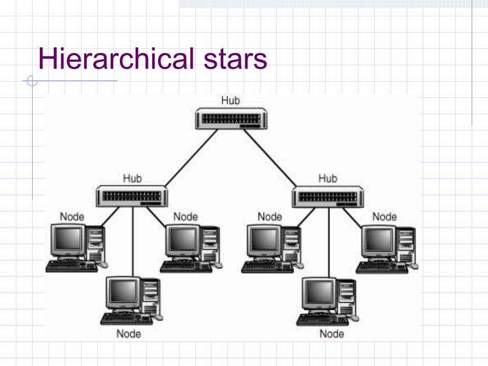
Hierarchical stars

Hierarchical combinationsOverall network performance can be
enhanced by not force-fitting all the functional requirements of the LAN into a single solution
Today’s high-end switching hubs enable you to mix multiple technologies

Hierarchical combinations

WAN Topologies
The topology of a WAN describes the way the transmission facilities are arranged relative to the locations that they interconnect
Numerous topologies are possible, each one offering a different mix of cost, performance and scalability

WAN Topologies Peer-to-peer WANs Ring WANs Star WANs Full-mesh WANs Partial-mesh WANs Two-tiered Three-tiered Hybrids

Peer-to-peer topologyA peer-to-peer WAN can be developed
using leased private lines or any other transmission facility
This WAN topology is a relatively simple way of interconnecting a small number of sites
Represents the least-cost solution for WANs that contain a small number of internetworked locations

Peer-to-peer

Advantage/Disadvantage of Peer-to-peerAdvantage:
It is inexpensive relative to other optionsDisadvantages:
They don’t scale very well. As additional locations are introduced to the WAN, the number of hops between any given pair of locations remains highly inconsistent and has an upward trend
An equipment or facility failure anywhere in a peer-to-peer WAN can split the WAN

Ring topologyCan be developed fairly easily from a peer-
to-peer network by adding one transmission facility and an extra port on two routers
A ring-shaped WAN constructed with point-to-point transmission facilities can be used to interconnect a small number of sites and provide route redundancy at a potentially minimal incremental cost
Can use dynamic routing protocols

Ring topology

Advantages/Disadvantages of Ring topologyAdvantages:
It provides alternative routes It is less expensive than all but the peer-to-peer
WANDisadvantages:
Depending on the geographic dispersion of the locations, adding an extra transmission facility to complete the ring may be cost prohibitive
Rings are not very scalable

Star network Topologyconstructed by homing all locations into
a common locationThe star topology can be constructed
using almost any dedicated transmission facility including frame relay and point-to-point private lines
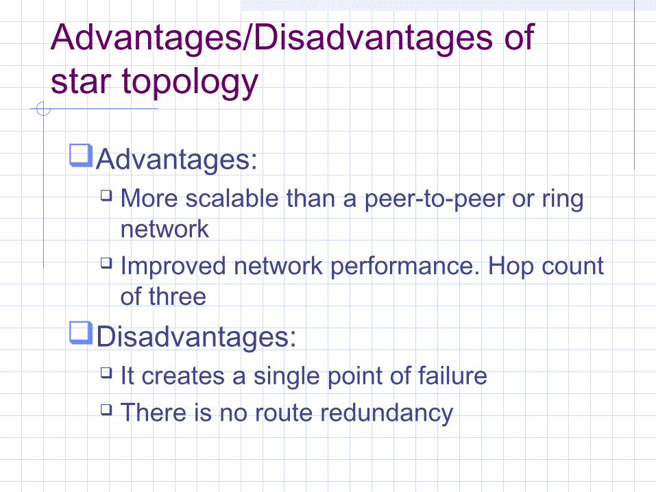
Advantages/Disadvantages of star topology
Advantages: More scalable than a peer-to-peer or ring
network Improved network performance. Hop count
of threeDisadvantages:
It creates a single point of failure There is no route redundancy

Star topology
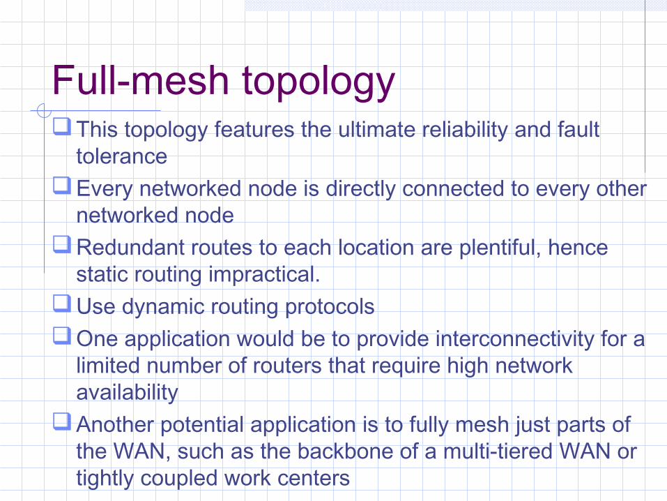
Full-mesh topologyThis topology features the ultimate reliability and fault
toleranceEvery networked node is directly connected to every other
networked nodeRedundant routes to each location are plentiful, hence
static routing impractical. Use dynamic routing protocolsOne application would be to provide interconnectivity for a
limited number of routers that require high network availability
Another potential application is to fully mesh just parts of the WAN, such as the backbone of a multi-tiered WAN or tightly coupled work centers

Advantages/Disadvantages of full-meshAdvantages:
Minimizes the number of hops between any two network-connected machines
Can be built with virtually any transmission technology
Disadvantages: These WANs can be fairly expensive to
build A finite (although substantial) limit on the
scalability of the network

Full-mesh topology

Partial-mesh topologyPartial meshes are highly flexible topologies
that can take a variety of very different configurations
The routers are much more tightly coupled than any of the basic topologies but are not fully interconnected, as would be the case in a fully meshed network
A partially meshed WAN topology is readily identified by the almost complete interconnection of every node with every other node in the network

Partial-mesh

Advantages of partial-meshPartial meshes offer the capability to
minimize hops for the bulk of the WAN’s users
Unlike fully meshed networks, a partial mesh can reduce the startup and operational expenses by not interconnecting low-traffic segments of the WAN, hence more affordable and scalable

Two-tiered topologyA two-tiered topology is a modified
version of the basic star topology. Rather than single concentrator routers, two or more routers are used
A two-tiered WAN constructed with dedicated facilities offers improved fault tolerance over the simple star topology without compromising scalability

Two-tiered topology

Three-tiered topologyWANs that need to interconnect a very
large number of sites, or are built using smaller routers that can support only a few serial connections, may find the two-tiered architecture insufficiently scalable.
Therefore, adding a third tier may well provide the additional scalability they require

Three-tiered

Advantage/Disadvantage of three-tiered
Advantage: A three-tiered WAN constructed with
dedicated facilities offers even greater fault tolerance and scalability than the two-tiered topology
Disadvantage: Three-tiered networks are expensive to
build, operate and maintain

Hybrid topologies
Hybridization of multiple topologies is useful in larger, more complex networks
Multi-tiered networks, in particular, lend themselves to hybridization. A multi-tiered WAN can be hybridized by fully or partially meshing the backbone tier of routers
An effective hybrid topology may be developed in a multi-tiered WAN by using a fully meshed topology for the backbone nodes only

Hybrid topology

Categories of Networks
Local Area Network (LAN)Wide Area Network (WAN)Metropolitan Area Network (MAN)Personal Area Network (PAN)
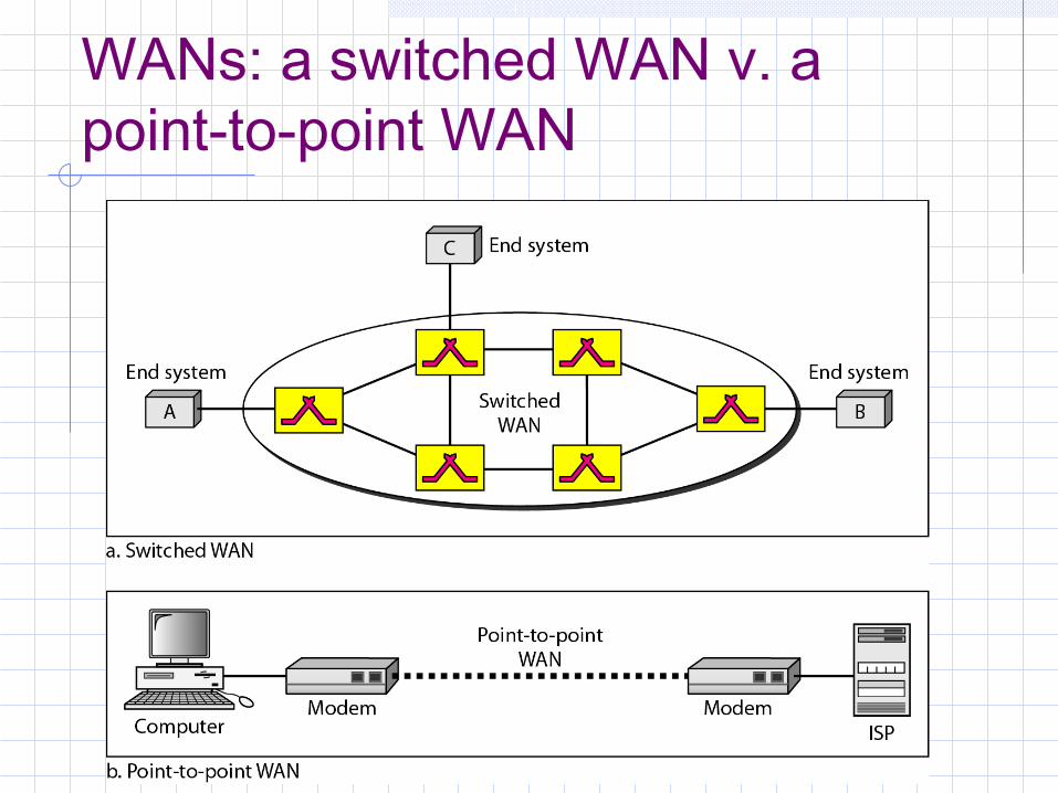
WANs: a switched WAN v. a point-to-point WAN
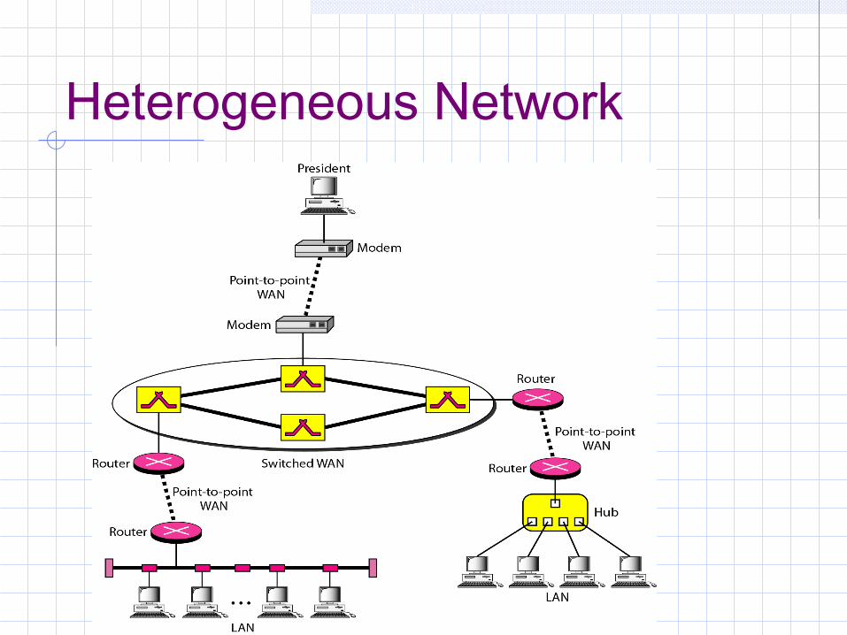
Heterogeneous Network

The Internet
The Internet has revolutionized many aspects of our daily lives. It has affected the way we do business as well as the way we spend our leisure time. The Internet is a communication system that has brought a wealth of information to our fingertips and organized it for our use.
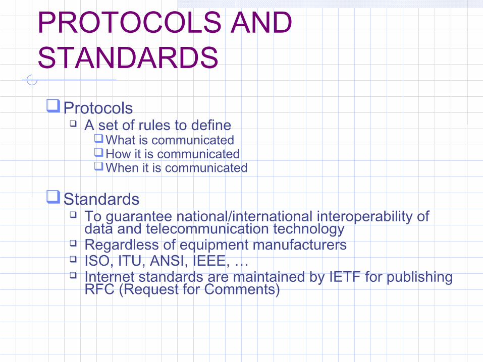
PROTOCOLS AND STANDARDSProtocols
A set of rules to defineWhat is communicatedHow it is communicatedWhen it is communicated
Standards To guarantee national/international interoperability of
data and telecommunication technology Regardless of equipment manufacturers ISO, ITU, ANSI, IEEE, … Internet standards are maintained by IETF for publishing
RFC (Request for Comments)

Thank You for watching!
MSA Technosofthttps://msatechnosoft.in/

Networking Devices
Introduction
• LANs do not normally operate in isolation but they are connected to one another or to the Internet.
• To connect LANs, connecting devices are needed and various connecting devices are such as bridge, switch, router, hub, repeater.

CONNECTING DEVICES
• Connecting devices into five different categories
based on the layer in which they operate in a
network.
Five categories of connecting devices

Hubs
• A hub is used as a central point of connection among media segments.
• Cables from network devices plug in to the ports on the hub.
• Types of HUBS :– A passive hub is just a connector. It connects the wires
coming from different branches.
– The signal pass through a passive hub without regeneration or amplification.
– Connect several networking cables together
– Active hubs or Multiport repeaters- They regenerate or amplify the signal before they are retransmitted.
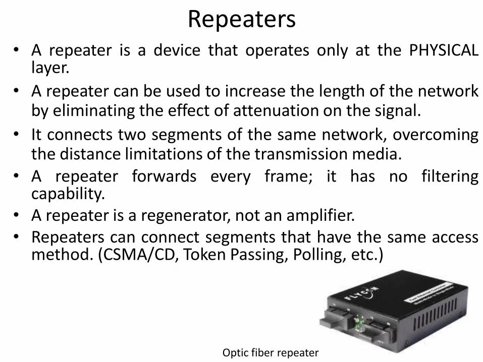
Repeaters• A repeater is a device that operates only at the PHYSICAL
layer.
• A repeater can be used to increase the length of the networkby eliminating the effect of attenuation on the signal.
• It connects two segments of the same network, overcomingthe distance limitations of the transmission media.
• A repeater forwards every frame; it has no filteringcapability.
• A repeater is a regenerator, not an amplifier.• Repeaters can connect segments that have the same access
method. (CSMA/CD, Token Passing, Polling, etc.)
Optic fiber repeater

Repeater connecting two segments of a LAN
Function of a repeater

Bridges• Operates in both the PHYSICAL and the data link layer.• As a PHYSICAL layer device, it regenerates the signal it
receives.• As a data link layer device, the bridge can check the
PHYSICAL/MAC addresses (source and destination)contained in the frame.
• A bridge has a table used in filtering decisions.
• It can check the destination address of a frame and decide if the frame should be forwarded or dropped.
• If the frame is to be forwarded, the decision must specify the port.
• A bridge has a table that maps address to ports.• Limit or filter traffic keeping local traffic local yet allow
connectivity to other parts (segments).

A bridge connecting two LANs
A bridge does not change the physical (MAC) addresses in a frame.
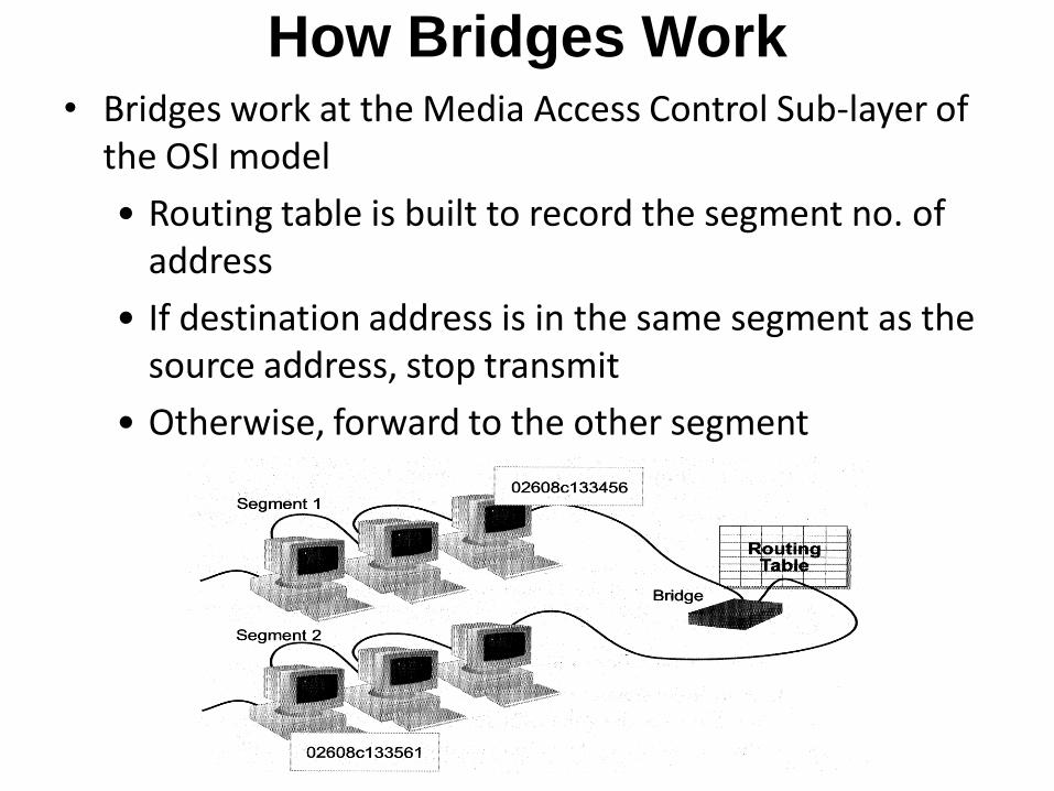
How Bridges Work• Bridges work at the Media Access Control Sub-layer of
the OSI model
• Routing table is built to record the segment no. of address
• If destination address is in the same segment as the source address, stop transmit
• Otherwise, forward to the other segment

Function of Bridge

Characteristics of Bridges• Routing Tables
– Contains one entry per station of network to which bridge is connected.
– Is used to determine the network of destination station of a received packet.
• Filtering– Is used by bridge to allow only those packets destined to
the remote network.– Packets are filtered with respect to their destination and
multicast addresses.• Forwarding
– the process of passing a packet from one network to another.
• Learning Algorithm– the process by which the bridge learns how to reach
stations on the internetwork.

Types of Bridges
• Transparent Bridge– Also called learning bridges– Build a table of MAC addresses as frames arrive– Ethernet networks use transparent bridge– Duties of transparent bridge are : Filtering frames,
forwarding and blocking
• Source Routing Bridge– Used in Token Ring networks– Each station should determine the route to the
destination when it wants to send a frame and therefore include the route information in the header of frame.
– Addresses of these bridges are included in the frame.– Frame contains not only the source and destination
address but also the bridge addresses.

Advantages And Disadvantages Of Bridges
• Advantages of using a bridge– Extend physical network
– Reduce network traffic with minor segmentation
– Creates separate collision domains
– Reduce collisions
– Connect different architecture
• Disadvantages of using bridges– Slower that repeaters due to filtering
– Do not filter broadcasts
– More expensive than repeaters

Two and Three layer switches
• Two layer switch operate at PHY and data link layer
• Three layer switch operates at network layer• Bridge is an example of two-layer switch.• Bridge with few port can connect a few LANs• Bridge with many port may be able to allocate
a unique port to each station, with each station on its own independent entity. This means no competing traffic (no collision as we saw in Ethernet)
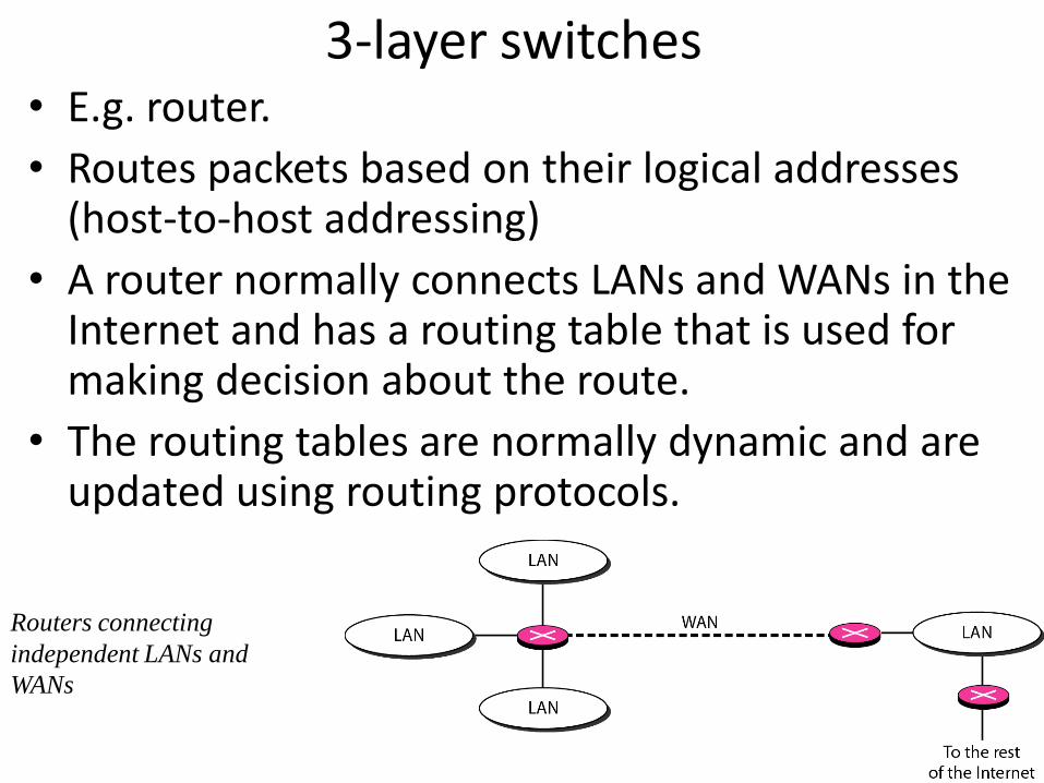
3-layer switches• E.g. router.
• Routes packets based on their logical addresses (host-to-host addressing)
• A router normally connects LANs and WANs in the Internet and has a routing table that is used for making decision about the route.
• The routing tables are normally dynamic and are updated using routing protocols.
Routers connecting
independent LANs and
WANs

Advantages and Disadvantages of Routers• Advantages
– Routers
provide sophisticated routing, flow control, and traffic isolation
are configurable, which allows network manager to make policy based on routing decisions
allow active loops so that redundant paths are available
• Disadvantages– Routers
– are protocol-dependent devices that must understand the protocol they are forwarding.
– can require a considerable amount of initial configuration.
– are relatively complex devices, and generally are more expensive than bridges.

Routers versus Bridges• Addressing
– Routers are explicitly addressed.
– Bridges are not addressed.
• Availability
– Routers can handle failures in links, stations, and other routers.
– Bridges use only source and destination MAC address, which does not guarantee delivery of frames.
Message Size » Routers can perform fragmentation on packets and thus handle
different packet sizes.» Bridges cannot do fragmentation and should not forward a
frame which is too big for the next LAN. Forwarding
» Routers forward a message to a specific destination.» Bridges forward a message to an outgoing network.

Priority» Routers can treat packets according to priorities» Bridges treat all packets equally.
Error Rate
» Network layers have error-checking algorithms that examines each received packet.
» The MAC layer provides a very low undetected bit error rate.
Security
» Both bridges and routers provide the ability to put “security walls” around specific stations.
» Routers generally provide greater security than bridges because
– they can be addressed directly and
– they use additional data for implementing security.

Brouters: Bridging Routers
Combine features of bridges and routers.
Capable of establishing a bridge between two
networks as well as routing some messages from the
bridge networks to other networks.
Are sometimes called (Layer 2/3) switches and are a
combination of bridge/router hardware and software.
Gateway• Interchangeably used term router and gateway• Connect two networks above the network layer of OSI
model.• Are capable of converting data frames and network
protocols into the format needed by another network.• Provide for translation services between different
computer protocols.• Transport gateways make a connection between two
networks at the transport layer.• Application gateways connect two parts of an
application in the application layer, e.g., sending email between two machines using different mail formats
• Broadband-modem-router is one e.g. of gateway


