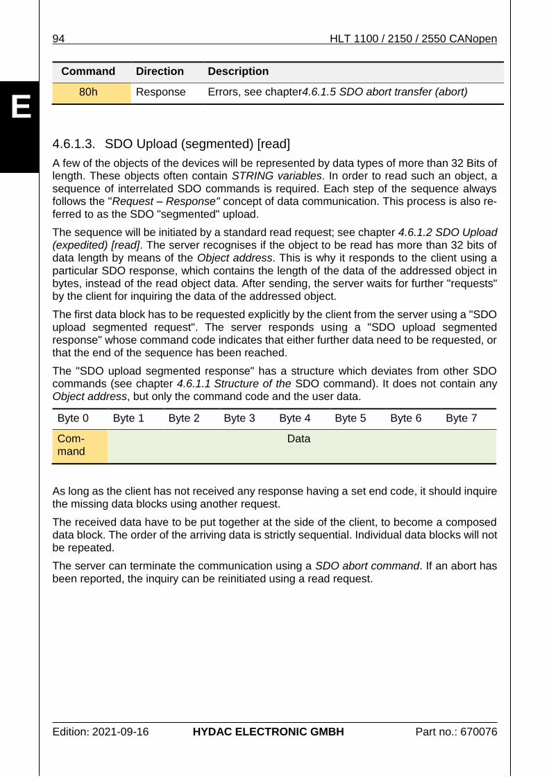
Linear Position Transmitter HLT 1100 -R2 CAN HLT 2150 -R1 CAN HLT 2550 -L2 CAN CANopen Modifikation: 000 Part No.: 670076 / Edition: 2021-09-16 E Protocol Description (Translation of original instructions)
Transcript
Linear Position Transmitter
HLT 1100 -R2 CAN
HLT 2150 -R1 CAN
HLT 2550 -L2 CAN
CANopen
Modifikation: 000
P
art
No
.: 6
70
07
6 / E
ditio
n:
20
21
-09
-16 E
Protocol Description (Translation of original instructions)
2 HLT 1100 / 2150 / 2550 CANopen
Edition: 2021-09-16 HYDAC ELECTRONIC GMBH Part no.: 670076
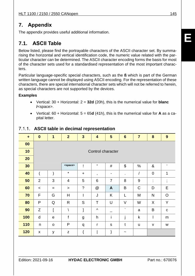
ASCII table in decimal representation ............................................................................. 145
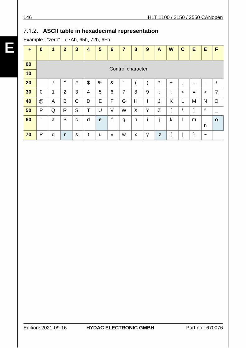
ASCII table in hexadecimal representation ...................................................................... 146
6 HLT 1100 / 2150 / 2550 CANopen
Edition: 2021-09-16 HYDAC ELECTRONIC GMBH Part no.: 670076
E
Preface This documentation describes the intended use of the product within a superordinate control system. It will help you to get acquainted with the provided communication inter-face and assist you in obtaining maximum benefit in the possible applications for which it is designed.
The specifications given in this documentation represent the state-of-the-art of the pro-duct at the time of publishing. Modifications to technical specifications, illustrations and dimensions are therefore possible.
The electronic document version contains many active cross-refe-rences, which are written in italics.
General product information, definition of the scope of applications, symbols used, as well as abbreviations.
Quick guide
In this chapter, the experienced users will find the factory pre-set process data signals as well es the device's own specifications supported by the measurement system.
Process data
Description of all signals provided as process data by the measurement system.
Parameters
Adjustable parameters for the communication or the functions of the measurement system.
Protocol description CANopen
Description of the report used This chapter describes principles and examples helping to facilitate the communication with the measurement system.
Subsequent Chapters
All chapters subsequent to the protocol description provide additional and useful infor-mation for the commissioning and application of the measurement system.
HLT 1100 / 2150 / 2550 CANopen 7
Edition: 2021-09-16 HYDAC ELECTRONIC GMBH Part no.: 670076
E
1. General information
This protocol description, including the illustrations contained therein, is subject to copyright protection. Use of this document by third parties in contravention of copyright regulations is forbidden. Reproduction, translation as well as electronic and photographic archiving and modification require the written permission of the manufacturer. Offenders will be liable for damages.
Before commissioning of the product, please read the related operating instructions as well as the associated protocol description. Ensure that the unit described, hereinafter referred to as measuring system, is suitable for your application.
Before each startup, installation or replacement, the measurement sys-tem including related accessories has to undergo a visual check for da-mage.
If the instrument is not handled correctly, or if the operating instructions and specifications are not adhered to, damage to property and/or perso-nal injury can result.
1.1. Scope of applications
This protocol description exclusively applies to the following measurement system types for the detection of linear movements. The products covered by this description can be identi-fied by means of the following model code structure:
CANopen: HLT 1100-R2-xxx-F11-xxxx-000
HLT 2150-R1-008-F11-xxxx-000
HLT 2550-L2-008-F11-xxxx-000
o Only the positions in the model code marked by "x" can be freely occupied using the attributes listed in the data sheet.
The products are components of a system or machine, labelled with affixed nameplates.
The following documentation should therefore always be read together:
System and machine-specific operating manuals of the operator
The related instruction manual
This protocol description for CANopen
8 HLT 1100 / 2150 / 2550 CANopen
Edition: 2021-09-16 HYDAC ELECTRONIC GMBH Part no.: 670076
E
1.2. Exclusion of liability
This protocol description was prepared to the best of our knowledge. Nevertheless and de-spite the greatest care, it cannot be excluded that mistakes could have crept in. Therefore please understand that in the absence of any provisions to the contrary hereinafter our war-ranty and liability – for any legal reasons whatsoever – are excluded in respect of the infor-mation in this operating manual.
In the event of translation, only the original version of the protocol description in German is legally valid.
In particular, we shall not be liable for lost profit or other financial loss. This exclusion of liability does not apply in cases of intent or gross negligence. Moreover, it does not apply to defects which have been deceitfully concealed or whose absence has been guaranteed, nor in cases of culpable harm to life, physical injury and damage to health. If we negligently breach any material contractual obligation, our liability shall be limited to foreseeable da-mage. Claims due to the product liability shall remain unaffected.
1.3. Symbols
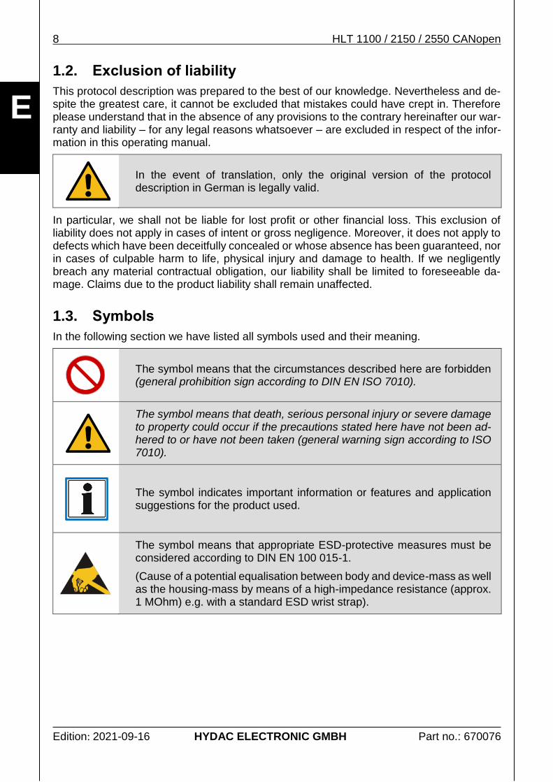
In the following section we have listed all symbols used and their meaning.
The symbol means that the circumstances described here are forbidden (general prohibition sign according to DIN EN ISO 7010).
The symbol means that death, serious personal injury or severe damage to property could occur if the precautions stated here have not been ad-hered to or have not been taken (general warning sign according to ISO 7010).
The symbol indicates important information or features and application suggestions for the product used.
The symbol means that appropriate ESD-protective measures must be considered according to DIN EN 100 015-1.
(Cause of a potential equalisation between body and device-mass as well as the housing-mass by means of a high-impedance resistance (approx. 1 MOhm) e.g. with a standard ESD wrist strap).
HLT 1100 / 2150 / 2550 CANopen 9
Edition: 2021-09-16 HYDAC ELECTRONIC GMBH Part no.: 670076
E
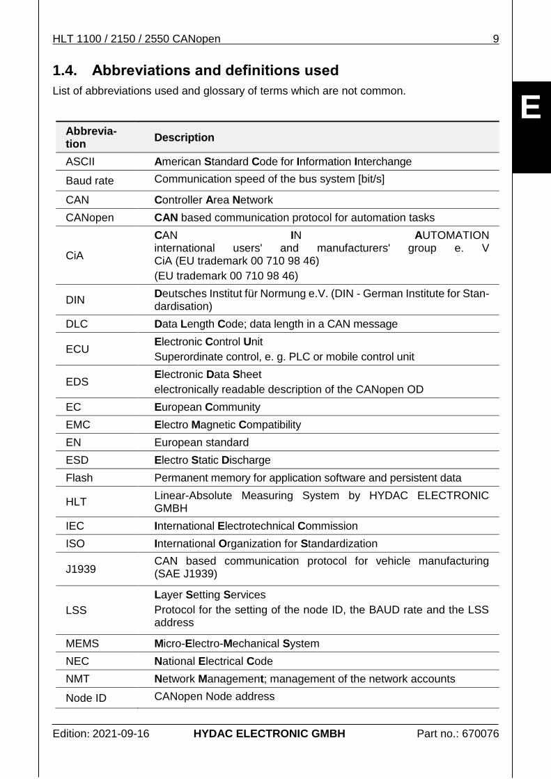
1.4. Abbreviations and definitions used
List of abbreviations used and glossary of terms which are not common.
Abbrevia-tion
Description
ASCII American Standard Code for Information Interchange
Baud rate Communication speed of the bus system [bit/s]
CAN Controller Area Network
CANopen CAN based communication protocol for automation tasks
CiA
CAN IN AUTOMATION international users' and manufacturers' group e. V CiA (EU trademark 00 710 98 46)
(EU trademark 00 710 98 46)
DIN Deutsches Institut für Normung e.V. (DIN - German Institute for Stan-dardisation)
DLC Data Length Code; data length in a CAN message
ECU Electronic Control Unit
Superordinate control, e. g. PLC or mobile control unit
EDS Electronic Data Sheet
electronically readable description of the CANopen OD
EC European Community
EMC Electro Magnetic Compatibility
EN European standard
ESD Electro Static Discharge
Flash Permanent memory for application software and persistent data
HLT Linear-Absolute Measuring System by HYDAC ELECTRONIC GMBH
IEC International Electrotechnical Commission
ISO International Organization for Standardization
J1939 CAN based communication protocol for vehicle manufacturing (SAE J1939)
LSS
Layer Setting Services
Protocol for the setting of the node ID, the BAUD rate and the LSS address
MEMS Micro-Electro-Mechanical System
NEC National Electrical Code
NMT Network Management; management of the network accounts
Node ID CANopen Node address
10 HLT 1100 / 2150 / 2550 CANopen
Edition: 2021-09-16 HYDAC ELECTRONIC GMBH Part no.: 670076
E
Abbrevia-tion
Description
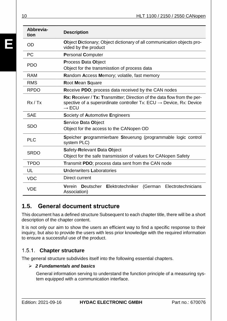
OD Object Dictionary; Object dictionary of all communication objects pro-vided by the product
PC Personal Computer
PDO Process Data Object
Object for the transmisstion of process data
RAM Random Access Memory; volatile, fast memory
RMS Root Mean Square
RPDO Receive PDO; process data received by the CAN nodes
Rx / Tx Rx: Receiver / Tx: Transmitter; Direction of the data flow from the per-spective of a superordinate controller Tx: ECU → Device, Rx: Device → ECU
SAE Society of Automotive Engineers
SDO Service Data Object
Object for the access to the CANopen OD
PLC Speicher programmierbare Steuerung (programmable logic control system PLC)
SRDO Safety-Relevant Data Object
Object for the safe transmission of values for CANopen Safety
TPDO Transmit PDO; process data sent from the CAN node
UL Underwriters Laboratories
VDC Direct current
VDE Verein Deutscher Elektrotechniker (German Electrotechnicians Association)
1.5. General document structure
This document has a defined structure Subsequent to each chapter title, there will be a short description of the chapter content.
It is not only our aim to show the users an efficient way to find a specific response to their inquiry, but also to provide the users with less prior knowledge with the required information to ensure a successful use of the product.
Chapter structure
The general structure subdivides itself into the following essential chapters.
2 Fundamentals and basics
General information serving to understand the function principle of a measuring sys-tem equipped with a communication interface.
HLT 1100 / 2150 / 2550 CANopen 11
Edition: 2021-09-16 HYDAC ELECTRONIC GMBH Part no.: 670076
E
3 Product interface
All the product specific caracteristics are described here. Certain sections of this description may repeat and differ at the same time in the protocol description if the measurement system described herein deviates from the general protocol descrip-tion or if the properties of the protocol description are complemented.
4 Protocol description CANopen
In the general protocol description provides you with all information required for a successful communication. It explains, for instance, how the process data are trans-mitted with this specific communication protocol. In addition, it explains how to change the measurement system configuration.
Notes on using this documentation efficiently
In order to get quick access to particular subjects, this document is linked with active cross-references. They are formatted in italics.
This chapter 3.1 Quick guide is supposed to lead you to a response to the most frequently asked questions as quickly as possible.
Symbols and abbreviations are explained in the chapters 1.3 Symbols and 1.4 Abbreviations and definitions used.
The display of numeric figures is explained in chapter 2.2 Display of numeric figures.
Technical English terms are placed between quotation marks ("..").
1.6. Changes of technical terms in the context of "political correctness"
HYDAC Electronic GmbH continuously strive to respect human rights and every individual's dignity in any context. However, when it comes to communication technology, one technical term is still very common "Master – Slave".
In order to avoid this archaic and discriminating expression, the term has been replaced wherever possible in this documentation, using the following substitution: "Master – Device" ("Device" replacing "Slave"). Exceptions are only terms which are used in this form in official documentation. These exceptions are only used to make it easier for the reader to under-stand the connection between this documentation and the official documents.
12 HLT 1100 / 2150 / 2550 CANopen
Edition: 2021-09-16 HYDAC ELECTRONIC GMBH Part no.: 670076
E
2. Fundamentals and basics
The following sections will explain non-product specific information for a better under-standing of the functioning principle of a measurement system with a communication inter-face.
2.1. General communication characteristics
In general, the measurement systems are the end-nodes within a communication network. They do not take control of their superordinate network themselves. However, these devices are able to generate and send information spontaneously. In doing this, the measurement systems mainly serve as a data source - they generate process data.
The following types of information can be generated and processed by means of the mea-surement system.
Process data current actual or nominal values
Parameters System data for the device identification or configuration
Events Information on particular events, such as errors
The information types listed here are explained in more detail in the following chapters.
2.2. Display of numeric figures
The figures without additional marking are displayed as numeric figures with decimals (num-ber basis 10). For a more simple display of data blocks, however, hexadecimal representa-tion is also very commonly used (number basis 16). In our document, the hexadecimals are generally marked by an "h" as a suffix.
Decimal numbers, when displayed in a mixed representation, are marked with the additional suffix "d".
Binary numbers (number basis 2) are marked by suffix "b".
12h 12 hexadecimal → 18 decimal
A2h A2 hexadecimal → 162 decimal
16d 16 decimal → 10 hexadecimal
66 66 decimal → 42 hexadecimal
10b 10 binary → 2 decimal
Note
In other documentations, i.e. EDS files, you will also frequently encounter the format "0x1042". This way, the prefix "0x" marks the subsequent number as a hexadecimal.
When describing the entries in the OD (see chapter 4.5 The Object Dictionary), the index is always shown in hexadecimal notation, but without particular marking.
HLT 1100 / 2150 / 2550 CANopen 13
Edition: 2021-09-16 HYDAC ELECTRONIC GMBH Part no.: 670076
E
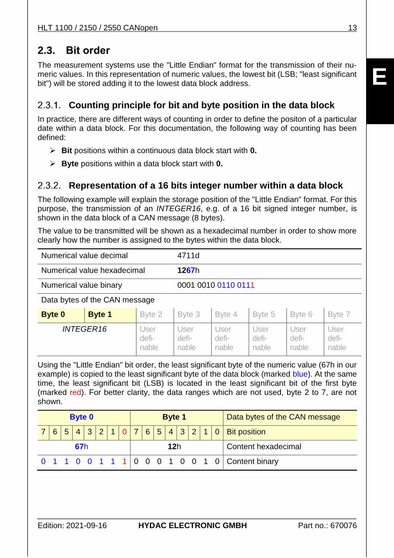
2.3. Bit order
The measurement systems use the "Little Endian" format for the transmission of their nu-meric values. In this representation of numeric values, the lowest bit (LSB; "least significant bit") will be stored adding it to the lowest data block address.
Counting principle for bit and byte position in the data block
In practice, there are different ways of counting in order to define the positon of a particular date within a data block. For this documentation, the following way of counting has been defined:
Bit positions within a continuous data block start with 0.
Byte positions within a data block start with 0.
Representation of a 16 bits integer number within a data block
The following example will explain the storage position of the "Little Endian" format. For this purpose, the transmission of an INTEGER16, e.g. of a 16 bit signed integer number, is shown in the data block of a CAN message (8 bytes).
The value to be transmitted will be shown as a hexadecimal number in order to show more clearly how the number is assigned to the bytes within the data block.
Using the "Little Endian" bit order, the least significant byte of the numeric value (67h in our example) is copied to the least significant byte of the data block (marked blue). At the same time, the least significant bit (LSB) is located in the least significant bit of the first byte (marked red). For better clarity, the data ranges which are not used, byte 2 to 7, are not shown.
Byte 0 Byte 1 Data bytes of the CAN message
7 6 5 4 3 2 1 0 7 6 5 4 3 2 1 0 Bit position
67h 12h Content hexadecimal
0 1 1 0 0 1 1 1 0 0 0 1 0 0 1 0 Content binary
14 HLT 1100 / 2150 / 2550 CANopen
Edition: 2021-09-16 HYDAC ELECTRONIC GMBH Part no.: 670076
E
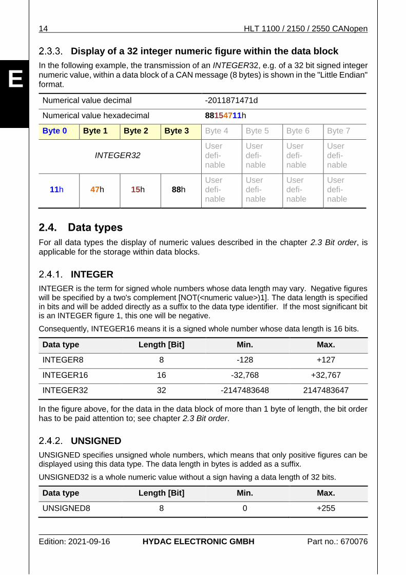
Display of a 32 integer numeric figure within the data block
In the following example, the transmission of an INTEGER32, e.g. of a 32 bit signed integer numeric value, within a data block of a CAN message (8 bytes) is shown in the "Little Endian" format.
For all data types the display of numeric values described in the chapter 2.3 Bit order, is applicable for the storage within data blocks.
INTEGER
INTEGER is the term for signed whole numbers whose data length may vary. Negative figures will be specified by a two's complement [NOT(<numeric value>)1]. The data length is specified in bits and will be added directly as a suffix to the data type identifier. If the most significant bit is an INTEGER figure 1, this one will be negative.
Consequently, INTEGER16 means it is a signed whole number whose data length is 16 bits.
Data type Length [Bit] Min. Max.
INTEGER8 8 -128 +127
INTEGER16 16 -32,768 +32,767
INTEGER32 32 -2147483648 2147483647
In the figure above, for the data in the data block of more than 1 byte of length, the bit order has to be paid attention to; see chapter 2.3 Bit order.
UNSIGNED
UNSIGNED specifies unsigned whole numbers, which means that only positive figures can be displayed using this data type. The data length in bytes is added as a suffix.
UNSIGNED32 is a whole numeric value without a sign having a data length of 32 bits.
Data type Length [Bit] Min. Max.
UNSIGNED8 8 0 +255
HLT 1100 / 2150 / 2550 CANopen 15
Edition: 2021-09-16 HYDAC ELECTRONIC GMBH Part no.: 670076
E
Data type Length [Bit] Min. Max.
UNSIGNED16 16 0 +65,535
UNSIGNED32 32 0 4294967295
In the figure above, for the data in the data block of more than 1 byte of length, the bit order has to be paid attention to; see chapter 2.3 Bit order.
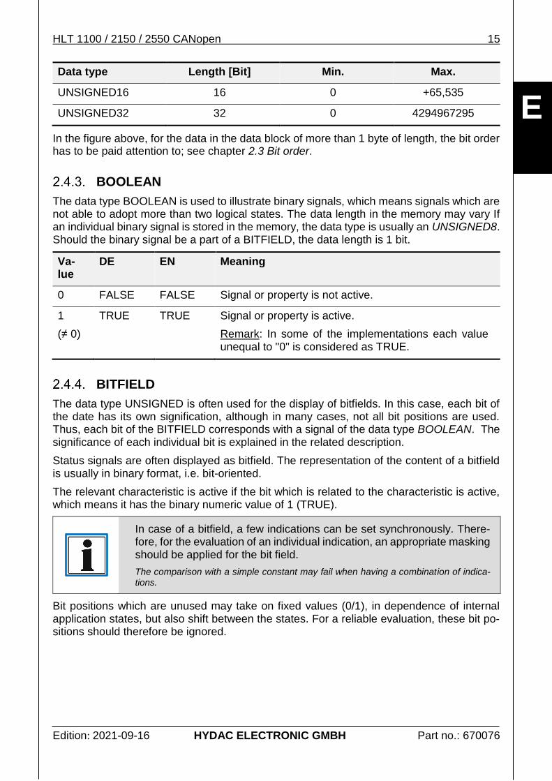
BOOLEAN
The data type BOOLEAN is used to illustrate binary signals, which means signals which are not able to adopt more than two logical states. The data length in the memory may vary If an individual binary signal is stored in the memory, the data type is usually an UNSIGNED8. Should the binary signal be a part of a BITFIELD, the data length is 1 bit.
Va-lue
DE EN Meaning
0 FALSE FALSE Signal or property is not active.
1
(≠ 0)
TRUE TRUE Signal or property is active.
Remark: In some of the implementations each value unequal to "0" is considered as TRUE.
BITFIELD
The data type UNSIGNED is often used for the display of bitfields. In this case, each bit of the date has its own signification, although in many cases, not all bit positions are used. Thus, each bit of the BITFIELD corresponds with a signal of the data type BOOLEAN. The significance of each individual bit is explained in the related description.
Status signals are often displayed as bitfield. The representation of the content of a bitfield is usually in binary format, i.e. bit-oriented.
The relevant characteristic is active if the bit which is related to the characteristic is active, which means it has the binary numeric value of 1 (TRUE).
In case of a bitfield, a few indications can be set synchronously. There-fore, for the evaluation of an individual indication, an appropriate masking should be applied for the bit field.
The comparison with a simple constant may fail when having a combination of indica-tions.
Bit positions which are unused may take on fixed values (0/1), in dependence of internal application states, but also shift between the states. For a reliable evaluation, these bit po-sitions should therefore be ignored.
16 HLT 1100 / 2150 / 2550 CANopen
Edition: 2021-09-16 HYDAC ELECTRONIC GMBH Part no.: 670076
E
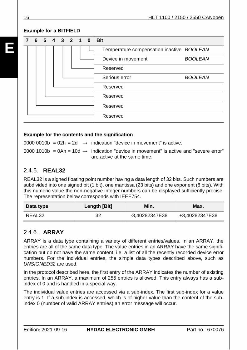
Example for a BITFIELD
7 6 5 4 3 2 1 0 Bit
Temperature compensation inactive BOOLEAN
Device in movement BOOLEAN
Reserved
Serious error BOOLEAN
Reserved
Reserved
Reserved
Reserved
Example for the contents and the signification
0000 0010b = 02h = 2d → indication "device in movement" is active.
0000 1010b = 0Ah = 10d → indication "device in movement" is active and "severe error" are active at the same time.
REAL32
REAL32 is a signed floating point number having a data length of 32 bits. Such numbers are subdivided into one signed bit (1 bit), one mantissa (23 bits) and one exponent (8 bits). With this numeric value the non-negative integer numbers can be displayed sufficiently precise. The representation below corresponds with IEEE754.
Data type Length [Bit] Min. Max.
REAL32 32 -3,40282347E38 +3,40282347E38
ARRAY
ARRAY is a data type containing a variety of different entries/values. In an ARRAY, the entries are all of the same data type. The value entries in an ARRAY have the same signifi-cation but do not have the same content, i.e. a list of all the recently recorded device error numbers. For the individual entries, the simple data types described above, such as UNSIGNED32 are used.
In the protocol described here, the first entry of the ARRAY indicates the number of existing entries. In an ARRAY, a maximum of 255 entries is allowed. This entry always has a sub-index of 0 and is handled in a special way.
The individual value entries are accessed via a sub-index. The first sub-index for a value entry is 1. If a sub-index is accessed, which is of higher value than the content of the sub-index 0 (number of valid ARRAY entries) an error message will occur.
HLT 1100 / 2150 / 2550 CANopen 17
Edition: 2021-09-16 HYDAC ELECTRONIC GMBH Part no.: 670076
E
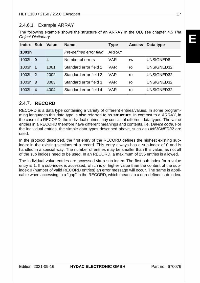
2.4.6.1. Example ARRAY
The following example shows the structure of an ARRAY in the OD, see chapter 4.5 The Object Dictionary.
Index Sub Value Name Type Access Data type
1003h
Pre-defined error field ARRAY
1003h 0 4 Number of errors VAR rw UNSIGNED8
1003h 1 1001 Standard error field 1 VAR ro UNSIGNED32
1003h 2 2002 Standard error field 2 VAR ro UNSIGNED32
1003h 3 3003 Standard error field 3 VAR ro UNSIGNED32
1003h 4 4004 Standard error field 4 VAR ro UNSIGNED32
RECORD
RECORD is a data type containing a variety of different entries/values. In some program-ming languages this data type is also referred to as structure. In contrast to a ARRAY, in the case of a RECORD, the individual entries may consist of different data types. The value entries in a RECORD therefore have different meanings and contents, i.e. Device code. For the individual entries, the simple data types described above, such as UNSIGNED32 are used.
In the protocol described, the first entry of the RECORD defines the highest existing sub-index in the existing sections of a record. This entry always has a sub-index of 0 and is handled in a special way. The number of entries may be smaller than this value, as not all of the sub indices need to be used. In an RECORD, a maximum of 255 entries is allowed.
The individual value entries are accessed via a sub-index. The first sub-index for a value entry is 1. If a sub-index is accessed, which is of higher value than the content of the sub-index 0 (number of valid RECORD entries) an error message will occur. The same is appli-cable when accessing to a "gap" in the RECORD, which means to a non-defined sub-index.
18 HLT 1100 / 2150 / 2550 CANopen
Edition: 2021-09-16 HYDAC ELECTRONIC GMBH Part no.: 670076
E
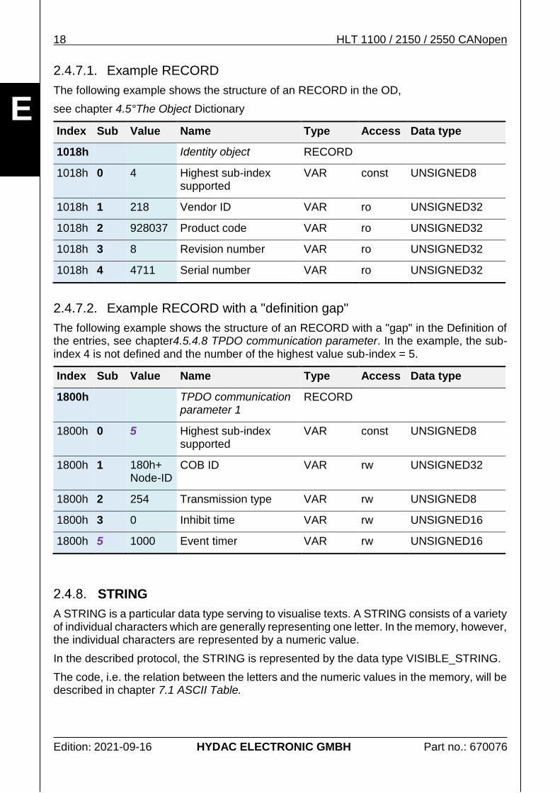
2.4.7.1. Example RECORD
The following example shows the structure of an RECORD in the OD,
see chapter 4.5°The Object Dictionary
Index Sub Value Name Type Access Data type
1018h Identity object RECORD
1018h 0 4 Highest sub-index supported
VAR const UNSIGNED8
1018h 1 218 Vendor ID VAR ro UNSIGNED32
1018h 2 928037 Product code VAR ro UNSIGNED32
1018h 3 8 Revision number VAR ro UNSIGNED32
1018h 4 4711 Serial number VAR ro UNSIGNED32
2.4.7.2. Example RECORD with a "definition gap"
The following example shows the structure of an RECORD with a "gap" in the Definition of the entries, see chapter4.5.4.8 TPDO communication parameter. In the example, the sub-index 4 is not defined and the number of the highest value sub-index = 5.
Index Sub Value Name Type Access Data type
1800h TPDO communication parameter 1
RECORD
1800h 0 5 Highest sub-index supported
VAR const UNSIGNED8
1800h 1 180h+ Node-ID
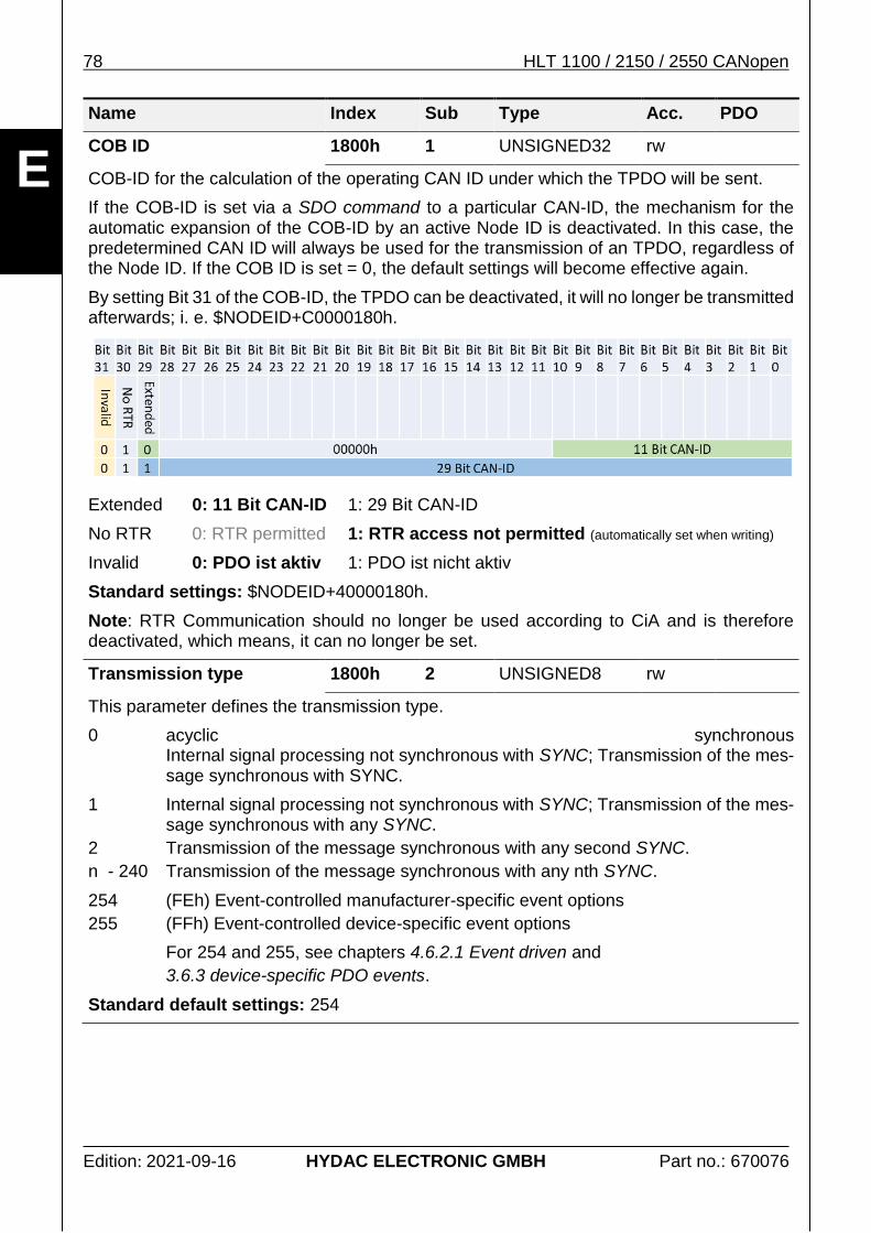
COB ID VAR rw UNSIGNED32
1800h 2 254 Transmission type VAR rw UNSIGNED8
1800h 3 0 Inhibit time VAR rw UNSIGNED16
1800h 5 1000 Event timer VAR rw UNSIGNED16
STRING
A STRING is a particular data type serving to visualise texts. A STRING consists of a variety of individual characters which are generally representing one letter. In the memory, however, the individual characters are represented by a numeric value.
In the described protocol, the STRING is represented by the data type VISIBLE_STRING.
The code, i.e. the relation between the letters and the numeric values in the memory, will be described in chapter 7.1 ASCII Table.
HLT 1100 / 2150 / 2550 CANopen 19
Edition: 2021-09-16 HYDAC ELECTRONIC GMBH Part no.: 670076
E
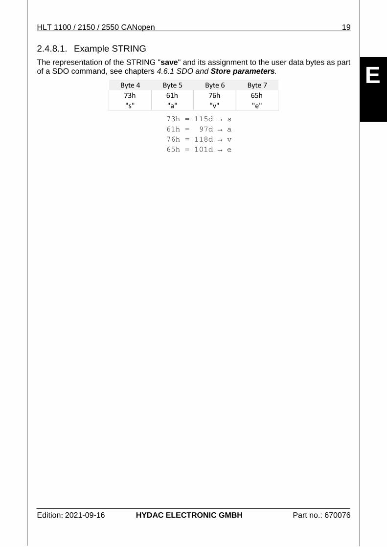
2.4.8.1. Example STRING
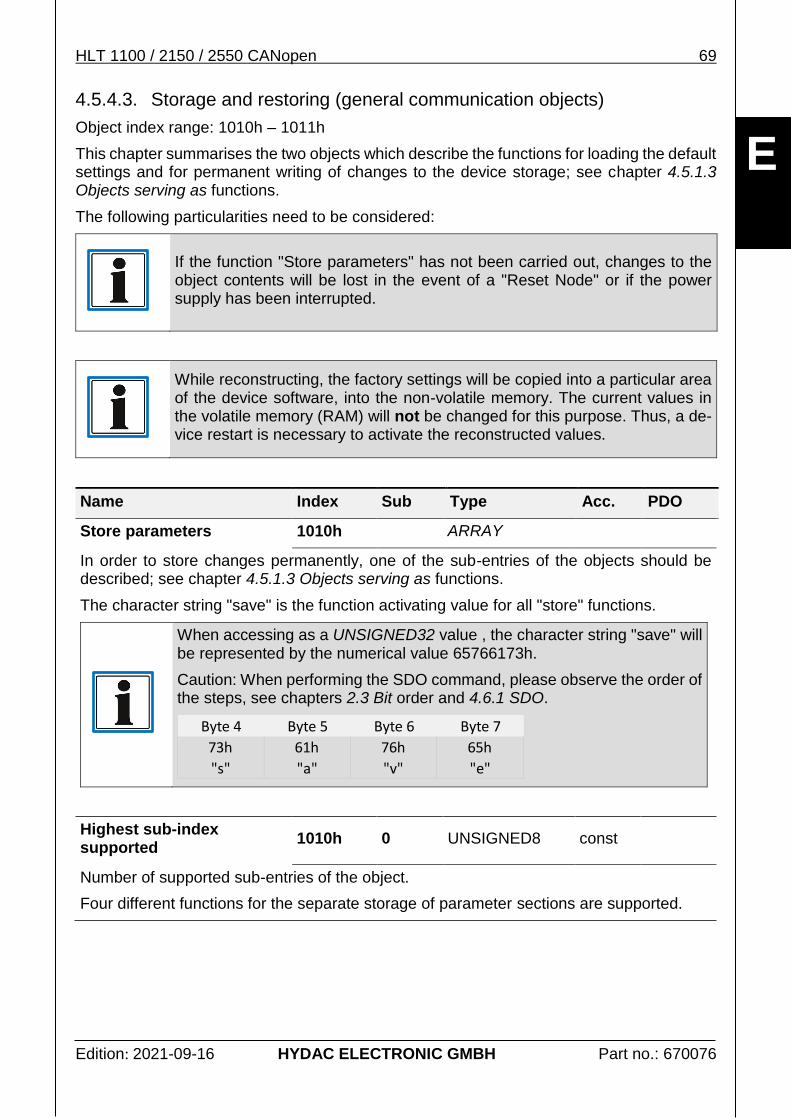
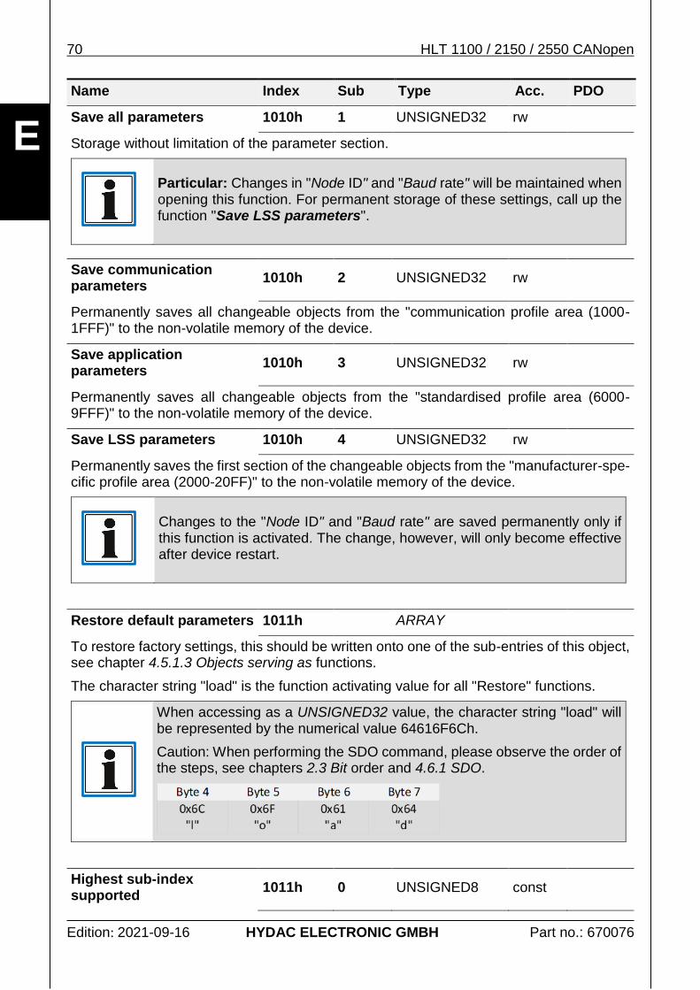
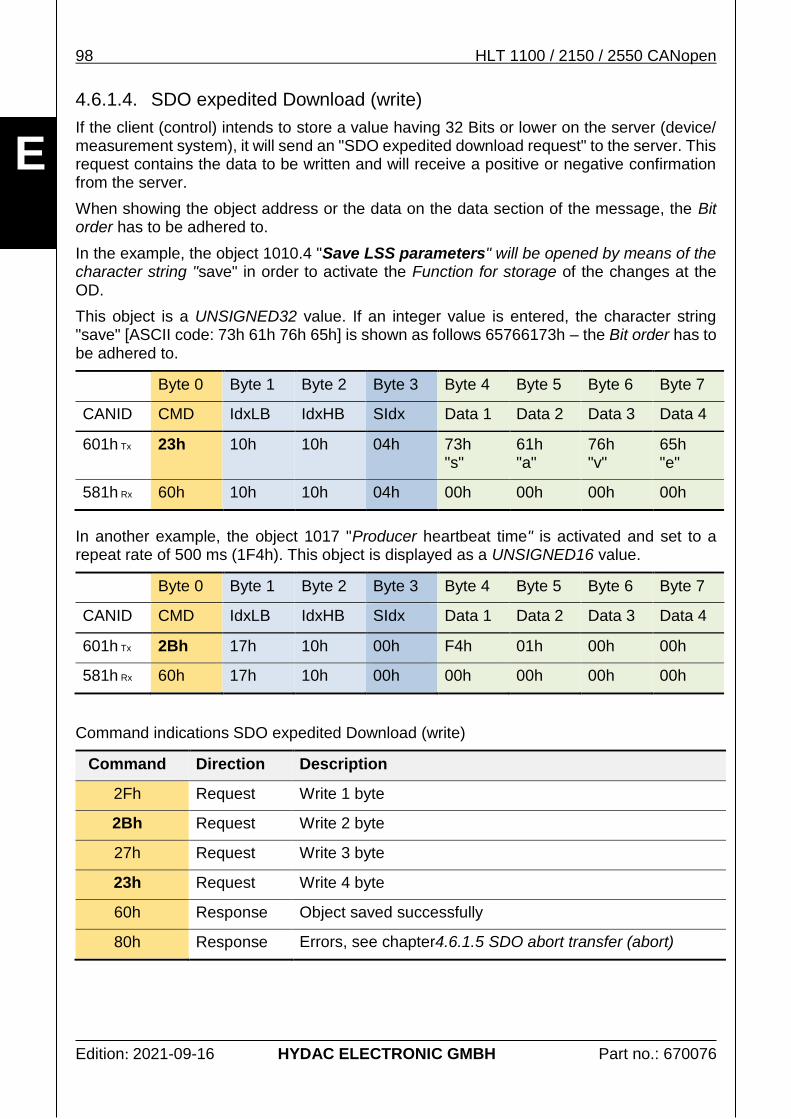
The representation of the STRING "save" and its assignment to the user data bytes as part of a SDO command, see chapters 4.6.1 SDO and Store parameters.
73h = 115d → s
61h = 97d → a
76h = 118d → v
65h = 101d → e
Byte 4 Byte 5 Byte 6 Byte 7
73h
"s"
61h
"a"
76h
"v"
65h
"e"
20 HLT 1100 / 2150 / 2550 CANopen
Edition: 2021-09-16 HYDAC ELECTRONIC GMBH Part no.: 670076
E
3. Product interface
Below, the actual communication characteristics of the measurement system will be explai-ned in a more detailed way. The structure of messages for the transmission of information, their functional context as well as their chronological sequence will be explained in a more detailed way in chapter 4 Protocol description CANopen.
3.1. Quick guide
This chapter is supposed to give the user quick responses to frequently occurring questions. For this purpose, the information is presented in the most compact way and provides cross-references to the related chapters for detailed information.
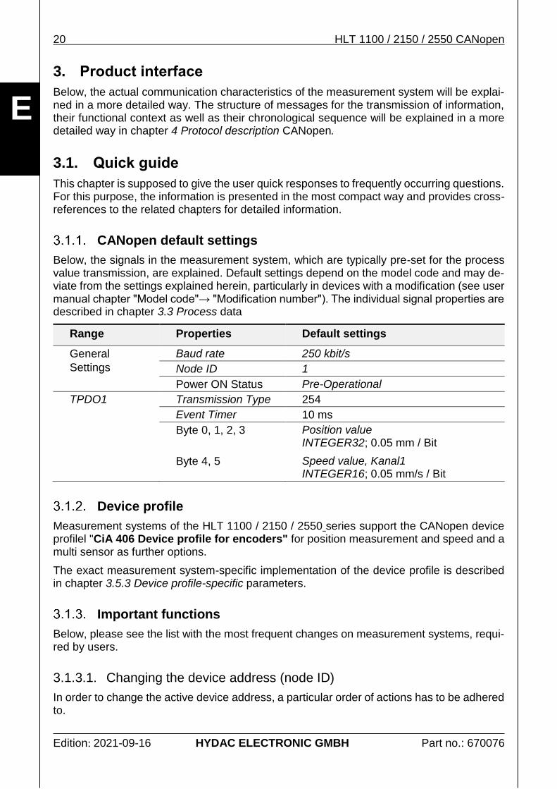
CANopen default settings
Below, the signals in the measurement system, which are typically pre-set for the process value transmission, are explained. Default settings depend on the model code and may de-viate from the settings explained herein, particularly in devices with a modification (see user manual chapter "Model code"→ "Modification number"). The individual signal properties are described in chapter 3.3 Process data
Range Properties Default settings
General
Settings
Baud rate 250 kbit/s
Node ID 1
Power ON Status Pre-Operational
TPDO1 Transmission Type 254
Event Timer 10 ms
Byte 0, 1, 2, 3 Position value
INTEGER32; 0.05 mm / Bit
Byte 4, 5 Speed value, Kanal1
INTEGER16; 0.05 mm/s / Bit
Device profile
Measurement systems of the HLT 1100 / 2150 / 2550 series support the CANopen device profilel "CiA 406 Device profile for encoders" for position measurement and speed and a multi sensor as further options.
The exact measurement system-specific implementation of the device profile is described in chapter 3.5.3 Device profile-specific parameters.
Important functions
Below, please see the list with the most frequent changes on measurement systems, requi-red by users.
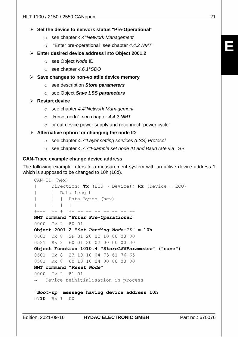
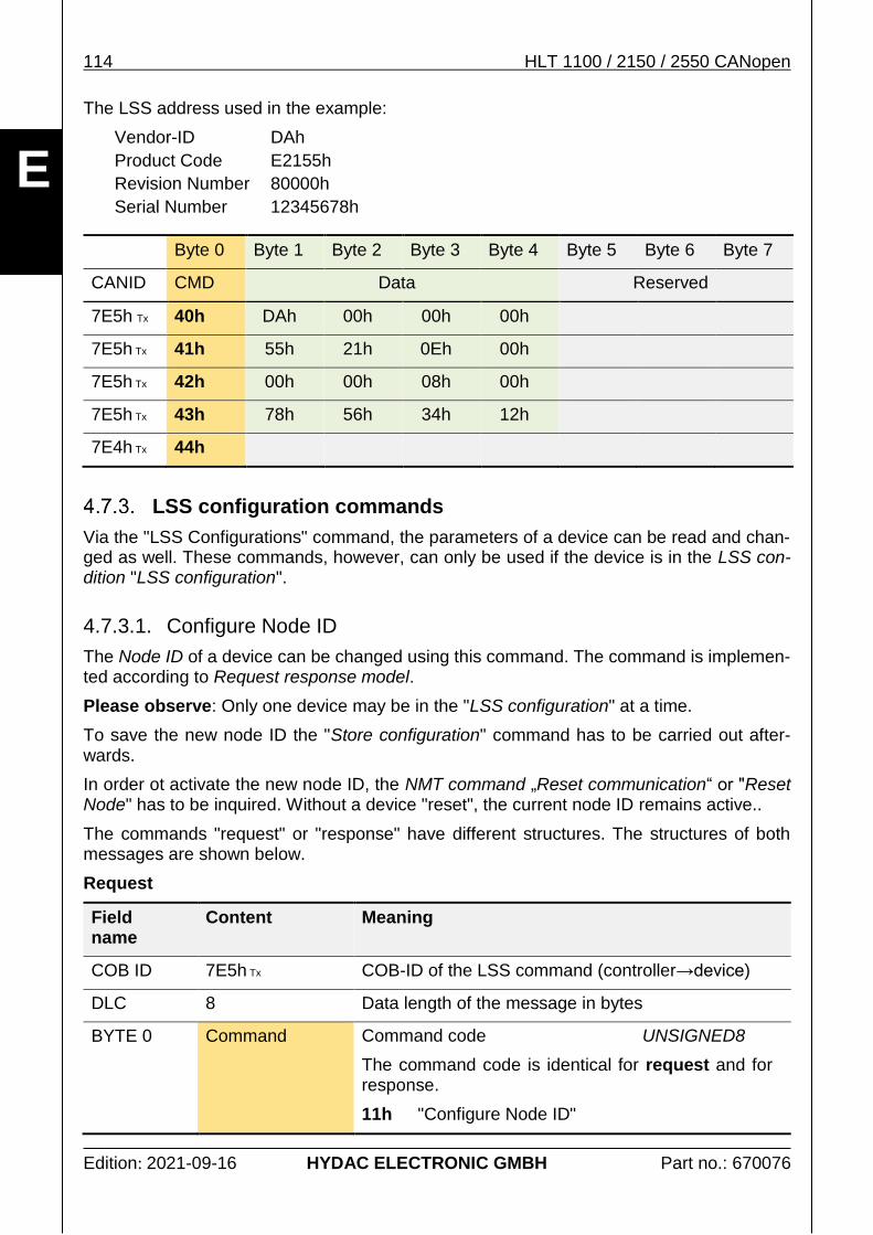
3.1.3.1. Changing the device address (node ID)
In order to change the active device address, a particular order of actions has to be adhered to.
HLT 1100 / 2150 / 2550 CANopen 21
Edition: 2021-09-16 HYDAC ELECTRONIC GMBH Part no.: 670076
E
Set the device to network status "Pre-Operational"
o see chapter 4.4°Network Management
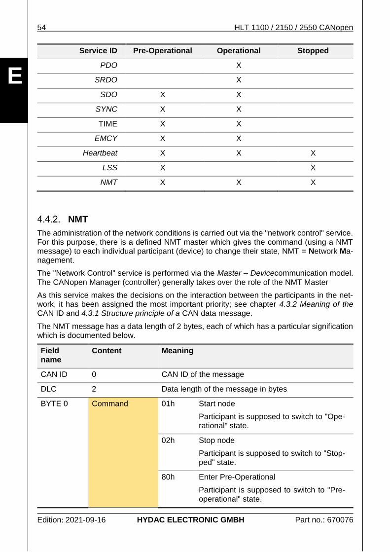
o "Enter pre-operational" see chapter 4.4.2 NMT
Enter desired device address into Object 2001.2
o see Object Node ID
o see chapter 4.6.1°SDO
Save changes to non-volatile device memory
o see description Store parameters
o see Object Save LSS parameters
Restart device
o see chapter 4.4°Network Management
o „Reset node“; see chapter 4.4.2 NMT
o or cut device power supply and reconnect "power cycle"
Alternative option for changing the node ID
o see chapter 4.7°Layer setting services (LSS) Protocol
o see chapter 4.7.7°Example set node ID and Baud rate via LSS
CAN-Trace example change device address
The following example refers to a measurement system with an active device address 1 which is supposed to be changed to 10h (16d).
CAN-ID (hex)
| Direction: Tx (ECU → Device); Rx (Device → ECU)
| | Data Length
| | | Data Bytes (hex)
| | | |
+--- +- + +- -- -- -- -- -- -- --
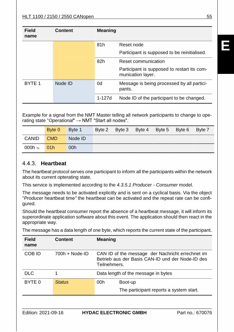
NMT command "Enter Pre-Operational"
0000 Tx 2 80 01
Object 2001.2 "Set Pending Node-ID" = 10h
0601 Tx 8 2F 01 20 02 10 00 00 00
0581 Rx 8 60 01 20 02 00 00 00 00
Object Function 1010.4 "StoreLSSParameter" ("save")
0601 Tx 8 23 10 10 04 73 61 76 65
0581 Rx 8 60 10 10 04 00 00 00 00
NMT command "Reset Node"
0000 Tx 2 81 01
→ Device reinitialisation in process
"Boot-up" message having device address 10h
0710 Rx 1 00
22 HLT 1100 / 2150 / 2550 CANopen
Edition: 2021-09-16 HYDAC ELECTRONIC GMBH Part no.: 670076
E
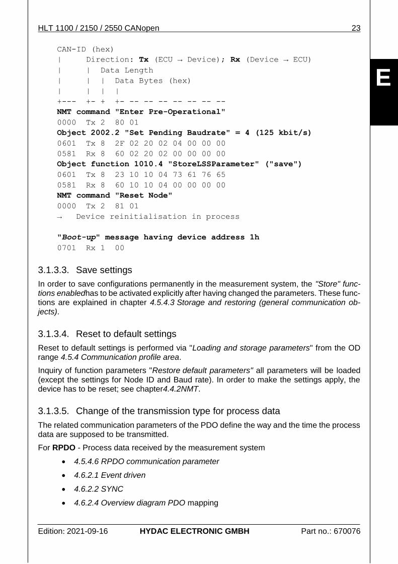
3.1.3.2. Change of the Baud rate
In order to change the Baud rate, a certain order of actions has to be adhered to. This process is very similar to changing the Node ID. Both changes may also be carried out simultaneously. For this purpose, the object of the Node ID also has to be changed in the second step.
Please note: after the Baud rate has been changed, it is also necessary to change it in the receiver's messages.
Sequence of actions Baud rate:
Set the device to network status "Pre-Operational"
o see chapter 4.4°Network Management
o "Enter pre-operational" see chapter 4.4.2 NMT
Enter desired Baud rate into Object 2002.2
o see Object Baud rate
o see chapter 4.6.1°SDO
o (option: additional change of Node ID, see object Node ID)
Save changes to non-volatile device memory
o see description Store parameters
o see Object Save LSS parameters
Restart device
o see chapter 4.4°Network Management
o „Reset node“; see chapter 4.4.2 NMT
o or cut device power supply and reconnect "power cycle"
Alternative option for changing the Baud rate
o see chapter 4.7°Layer setting services (LSS) Protocol
o see chapter 4.7.7°Example set node ID and Baud rate via LSS
CAN trace example change Baud rate
The following example refers to a measurement system with an active device address 1. The Baud rate is supposed to be changed to 125 kbit/s.
HLT 1100 / 2150 / 2550 CANopen 23
Edition: 2021-09-16 HYDAC ELECTRONIC GMBH Part no.: 670076
Object function 1010.4 "StoreLSSParameter" ("save")
0601 Tx 8 23 10 10 04 73 61 76 65
0581 Rx 8 60 10 10 04 00 00 00 00
NMT command "Reset Node"
0000 Tx 2 81 01
→ Device reinitialisation in process
"Boot-up" message having device address 1h
0701 Rx 1 00
3.1.3.3. Save settings
In order to save configurations permanently in the measurement system, the "Store" func-tions enabledhas to be activated explicitly after having changed the parameters. These func-tions are explained in chapter 4.5.4.3 Storage and restoring (general communication ob-jects).
3.1.3.4. Reset to default settings
Reset to default settings is performed via "Loading and storage parameters" from the OD range 4.5.4 Communication profile area.
Inquiry of function parameters "Restore default parameters" all parameters will be loaded (except the settings for Node ID and Baud rate). In order to make the settings apply, the device has to be reset; see chapter4.4.2NMT.
3.1.3.5. Change of the transmission type for process data
The related communication parameters of the PDO define the way and the time the process data are supposed to be transmitted.
For RPDO - Process data received by the measurement system
4.5.4.6 RPDO communication parameter
4.6.2.1 Event driven
4.6.2.2 SYNC
4.6.2.4 Overview diagram PDO mapping
24 HLT 1100 / 2150 / 2550 CANopen
Edition: 2021-09-16 HYDAC ELECTRONIC GMBH Part no.: 670076
E
For TPDO - Process data sent by the measurement system
4.5.4.8 TPDO communication parameter
4.6.2.1 Event driven
4.6.2.2 SYNC
4.6.2.4 Overview diagram PDO mapping
3.1.3.6. Change of the content of the process data
The content of the process data is administrated via the "PDO Mapping" see chapter 4.6.2.3 PDO Mapping and 4.6.2.4 Overview diagram PDO mapping.
To change the mapping, a defined process has to be adhered to, see chapter 4.6.2.5 Process flow sequence to change the "PDO mapping".
What to do if no process data have been recognised
As CANopen offers high flexibility, unfortunately, there are also many different causes for not transmitting or receiving the process data of a measurement system. In the following a few points are listed which should be checked if no data or no plausible data are being transmitted.
Network status "Pre-Operational"
A measuring system in the "Pre-Operation" state does not send any process data, see chapter 4.4.1 Overview network conditions.
The current network state can be read out from the "Heartbeat" protocol's data while this is active, see chapter 4.4.3 Heartbeat.
SYNC based PDO communication
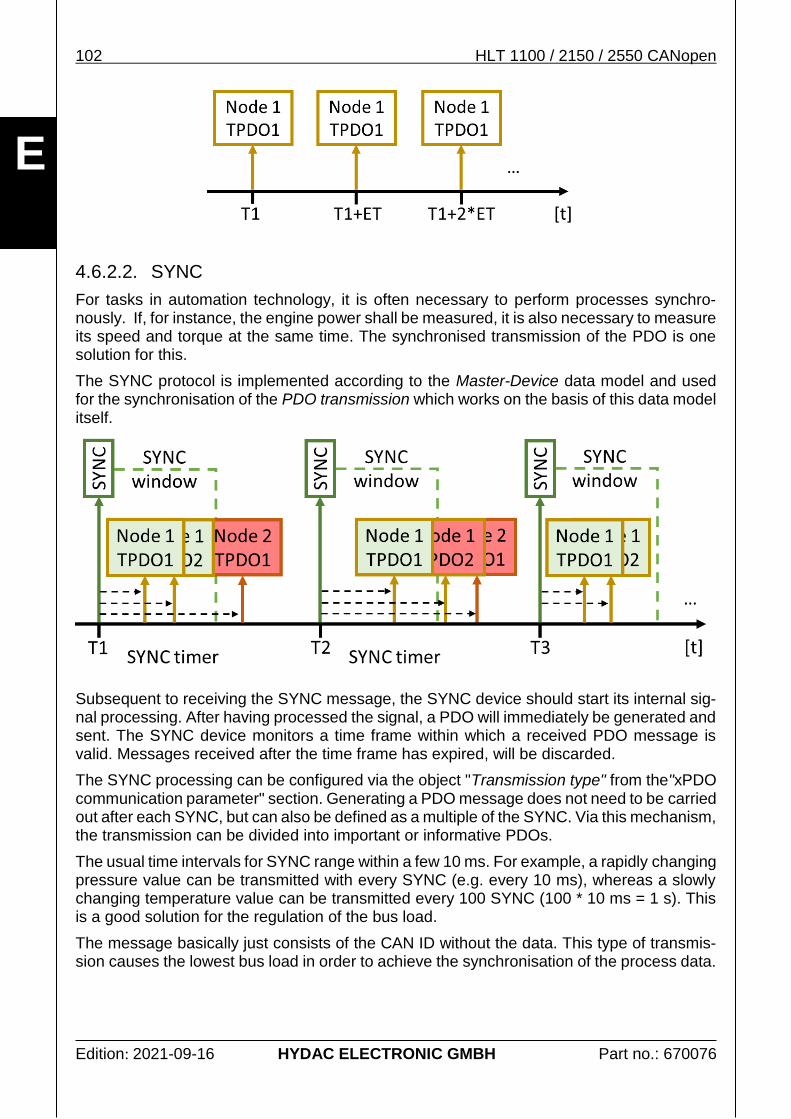
If, for the transmission of a PDO the SYNC service is active, the measurement sys-tem will either send a PDO only after receiving one or several SYNC messages or further process a received signal. No PDO will be exchanged without any SYNC messages.
Further information on how the SYNC processing is carried out and how it is activated is explained in the following chapters:
4.6.2.2 SYNC
4.5.4.8 TPDO communication parameter.
PDO COB-ID/CAN-ID parameter settings
By means of which CAN ID PDO will be transmitted is defined via the PDO's COB ID. The parameters for this will be explained in the following chapters: for RPDO 4.5.4.6and for TPDO 4.5.4.8.
The configuration options at the COB ID decide if a PDO may be sent at all an if the sender and the receiver work with the same ID.
o PDO transmission active
The indication "invalid" in the COB ID (bit 31) of a PDO decide if a PDO is sent/re-ceived at all, see object TPDO.COB-ID.
HLT 1100 / 2150 / 2550 CANopen 25
Edition: 2021-09-16 HYDAC ELECTRONIC GMBH Part no.: 670076
E
o CAN ID correctly evaluated
The PDO's CAN ID is usually calculated from the current Basis CAN ID and the current Node IDof the measurement system, see object TPDO.COB-ID.
It can easily happen that the receiver is still configured to respond to the "old" CAN ID, despite having changed the node ID of the measurement system. It may therefore occur that messages sent via the "new" CAN ID are ignored by the PDO.
Evaluation of process data
The correct evaluation of the process data is slightly more complicated. If ensured that the desired PDO is received, the desired Process valuehas to be copied from the CAN data blockand needs to be interpreted correctly.
If the present measurement system still has its factory default settings, the pre-set process data are described in chapter 3.1.1 CANopen default settings
If the measurement system already has an individual configuration, the mechanisms described in chapter 4.6.2 PDO will apply. Chapter 4.6.2.4 Overview diagram PDO mapping provides a good overview for this purpose.
3.2. Product description
The HLT 1100 / 2150 / 2550 series measurement systems are used to measure linear mo-vements and to condition the measured data for the subsequent control of mobile control procedures.
The following please find the most important information on this product. The indications listed herein are non-formal and are provided solely for the purpose of helping to understand the context. A more detailed description of the product properties is available in the associated opera-ting manual.
In case of doubt, the indications given in the operating manual always apply.
Position (distance)
The sensor works on the principle of magnetostriction. The measurement principle is based on a runtime measurement and provides highly precise measured values of the position (distance) of a permanent magnet in relation with a defined zero-position.
3.3.2 Signal Position
Speed
In addition to the linear movement, the measurement system also provides the magnet mo-vement speed. The speed detection is based on a runtime measurement as well.
3.3.3 Signal Speed
26 HLT 1100 / 2150 / 2550 CANopen
Edition: 2021-09-16 HYDAC ELECTRONIC GMBH Part no.: 670076
E
Additional signals
The HLT 1100 / 2150 / 2550 series measurement systems do not provide any further signals describing the linear movement in addition with the variables for position and speed.
3.3. Process data
The measurement system described herein represents a data source which means the pro-vided process data, actual values are the current measured values.
Further information explaining the meaning and the properties of process data can be found in chapter 4.6.2 PDO.
The measurement system described does not provide any additional manufacturer-specific measurement channels.
Structure of the signal description
All signals provided by the measurement system are written to in the same way. The im-portant measurands for the evaluation and conversion of the signal are listed in a table.
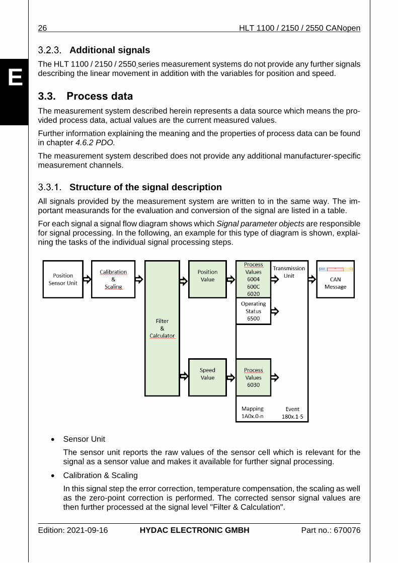
For each signal a signal flow diagram shows which Signal parameter objects are responsible for signal processing. In the following, an example for this type of diagram is shown, explai-ning the tasks of the individual signal processing steps.
Sensor Unit
The sensor unit reports the raw values of the sensor cell which is relevant for the signal as a sensor value and makes it available for further signal processing.
Calibration & Scaling
In this signal step the error correction, temperature compensation, the scaling as well as the zero-point correction is performed. The corrected sensor signal values are then further processed at the signal level "Filter & Calculation".
HLT 1100 / 2150 / 2550 CANopen 27
Edition: 2021-09-16 HYDAC ELECTRONIC GMBH Part no.: 670076
E
Filter or Filter & Calculator
On this signal level, the processed signal values are now converted and filtered to become the relevant process signal. Here, for instance, the position values are fil-tered from the position signals and the speed values are calculated.
Transmission Unit
If one of the following events occurs, the value of the PDO is sent depending on the preset Transmission Type.
1. The Event Timer has expired (cyclical transmission).
2. One or more SYNC objects have been received (synchronous transmission).
The cross-references are indicated as shown below:
Signal description Reference to the chapter, giving a short explana-tion of the relevant signal. A more detailed description can be found in the related operation manual.
Signal characteristics Refers to the chapter describing the characteris-tics necessary for the evaluation of the measuring range, for instance.
Status information Refers to the chapter which explains the exact structure of a status value belonging to a signal (mainly a BITFIELD).
The following table explains the meaning of the individual signal properties of a signal description.
Signal properties Description
Measurement range min. The smallest physical value displayable by the signal.
Measurement range max. The greatest physical value displayable by the signal.
Resolution The physical value of an individual bit of the numeric va-lue.
Definition of the conversion between numeric value of the data type and the physical size of the signal.
Example:
Numerical value: 4711d
Resolution: 0.01 °/bit
4711d * 0.01 °/Bit = 47.11 °
28 HLT 1100 / 2150 / 2550 CANopen
Edition: 2021-09-16 HYDAC ELECTRONIC GMBH Part no.: 670076
E
Signal properties Description
Offset Eventually existing zero offset of the numeric value.
An offset is mainly used if the data type of the transmitted numeric value is unsigned.
Example:
Numerical value: 61d
Measurement range: -40 bis +120 °C
Resolution: 1 °C/bit
Offset: -40 °C
(61d * 1 °C/Bit) + (-40 °C) = 21 °C
Data type Data type of the numeric signal value during transmis-sion; see chapter 2.4 Data types and 2.3 Bit order.
Data length Length of the data type used for the transmission in bits.
Mappable Defines if and which way the signal can be transmitted via CANopen Process data object.
TPDO, RPDO or SRDO.
Process value index Index number of the object with the current process value for the visualisation on a PDO.
Example:
6004.0 Position value (for single sensor devices)
600C.0 Position raw value
6020.1 Position value (for multi sensor devices)
6030.1 Speed value measurement channel 1
Default settings Describes if and via which Process data objectthe signal will be transmitted during emission:
TPDO, RPDO or SRDO.
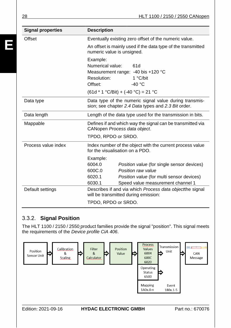
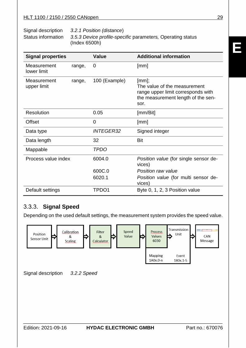
Signal Position
The HLT 1100 / 2150 / 2550 product families provide the signal "position". This signal meets the requirements of the Device profile CiA 406.
HLT 1100 / 2150 / 2550 CANopen 29
Edition: 2021-09-16 HYDAC ELECTRONIC GMBH Part no.: 670076
E
Signal description 3.2.1 Position (distance)
Status information 3.5.3 Device profile-specific parameters, Operating status (Index 6500h)
Signal properties Value Additional information
Measurement range, lower limit
0 [mm]
Measurement range, upper limit
100 (Example) [mm]; The value of the measurement range upper limit corresponds with the measurement length of the sen-sor.
Resolution 0.05 [mm/Bit]
Offset 0 [mm]
Data type INTEGER32 Signed integer
Data length 32 Bit
Mappable TPDO
Process value index 6004.0
600C.0
6020.1
Position value (for single sensor de-vices)
Position raw value
Position value (for multi sensor de-vices)
Default settings TPDO1 Byte 0, 1, 2, 3 Position value
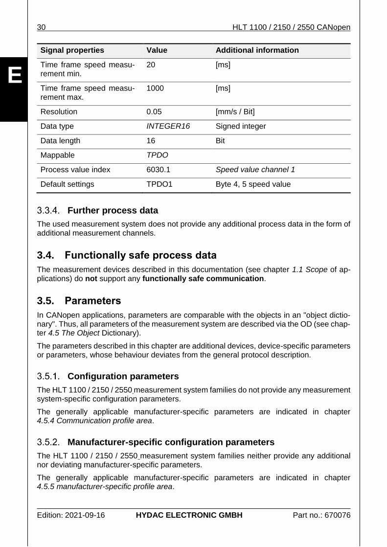
Signal Speed
Depending on the used default settings, the measurement system provides the speed value.
Signal description 3.2.2 Speed
30 HLT 1100 / 2150 / 2550 CANopen
Edition: 2021-09-16 HYDAC ELECTRONIC GMBH Part no.: 670076
E
Signal properties Value Additional information
Time frame speed measu-rement min.
20 [ms]
Time frame speed measu-rement max.
1000 [ms]
Resolution 0.05 [mm/s / Bit]
Data type INTEGER16 Signed integer
Data length 16 Bit
Mappable TPDO
Process value index 6030.1 Speed value channel 1
Default settings TPDO1 Byte 4, 5 speed value
Further process data
The used measurement system does not provide any additional process data in the form of additional measurement channels.
3.4. Functionally safe process data
The measurement devices described in this documentation (see chapter 1.1 Scope of ap-plications) do not support any functionally safe communication.
3.5. Parameters
In CANopen applications, parameters are comparable with the objects in an "object dictio-nary". Thus, all parameters of the measurement system are described via the OD (see chap-ter 4.5 The Object Dictionary).
The parameters described in this chapter are additional devices, device-specific parameters or parameters, whose behaviour deviates from the general protocol description.
Configuration parameters
The HLT 1100 / 2150 / 2550 measurement system families do not provide any measurement system-specific configuration parameters.
The generally applicable manufacturer-specific parameters are indicated in chapter 4.5.4 Communication profile area.
Manufacturer-specific configuration parameters
The HLT 1100 / 2150 / 2550 measurement system families neither provide any additional nor deviating manufacturer-specific parameters.
The generally applicable manufacturer-specific parameters are indicated in chapter 4.5.5 manufacturer-specific profile area.
HLT 1100 / 2150 / 2550 CANopen 31
Edition: 2021-09-16 HYDAC ELECTRONIC GMBH Part no.: 670076
E
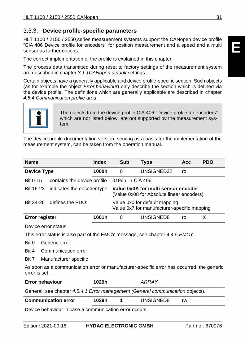
Device profile-specific parameters
HLT 1100 / 2150 / 2550 series measurement systems support the CANopen device profile "CiA 406 Device profile for encoders" for position measurement and a speed and a multi sensor as further options.
The correct implementation of the profile is explained in this chapter.
The process data transmitted during reset to factory settings of the measurement system are described in chapter 3.1.1CANopen default settings.
Certain objects have a generally applicable and device profile-specific section. Such objects (as for example the object Error behaviour) only describe the section which is defined via the device profile. The definitions which are generally applicable are described in chapter 4.5.4 Communication profile area.
The objects from the device profile CiA 406 "Device profile for encoders" which are not listed below, are not supported by the measurement sys-tem.
The device profile documentation version, serving as a basis for the implementation of the measurement system, can be taken from the operation manual.
Name Index Sub Type Acc PDO
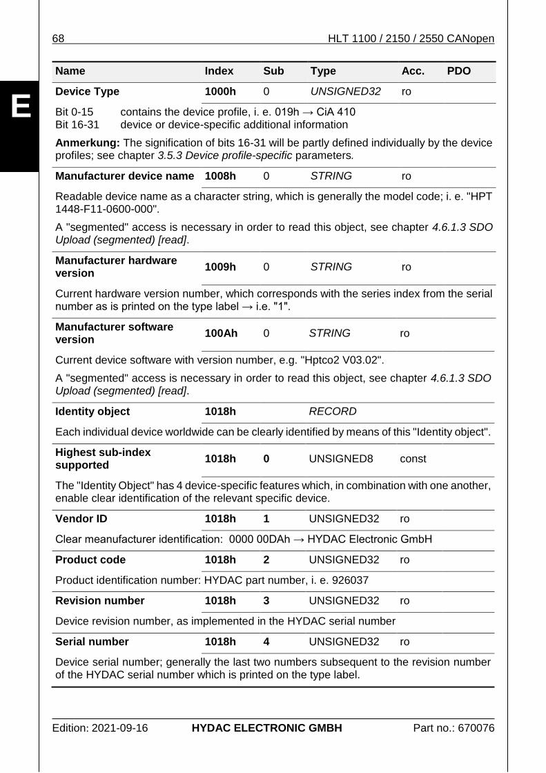
Device Type 1000h 0 UNSIGNED32 ro
Bit 0-15 contains the device profile 0196h → CiA 406
Bit 16-23 indicates the encoder type: Value 0x0A for multi sensor encoder (Value 0x08 for Absolute linear encoders)
Bit 24-26 defines the PDO: Value 0x0 for default mapping Value 0x7 for manufacturer-specific mapping
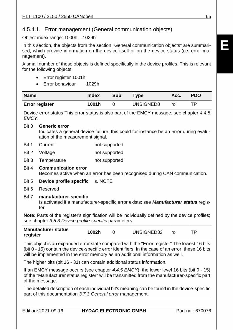
Error register 1001h 0 UNSIGNED8 ro X
Device error status
This error status is also part of the EMCY message, see chapter 4.4.5 EMCY.
Bit 0 Generic error
Bit 4 Communication error
Bit 7 Manufacturer specific
As soon as a communication error or manufacturer-specific error has occurred, the generic error is set.
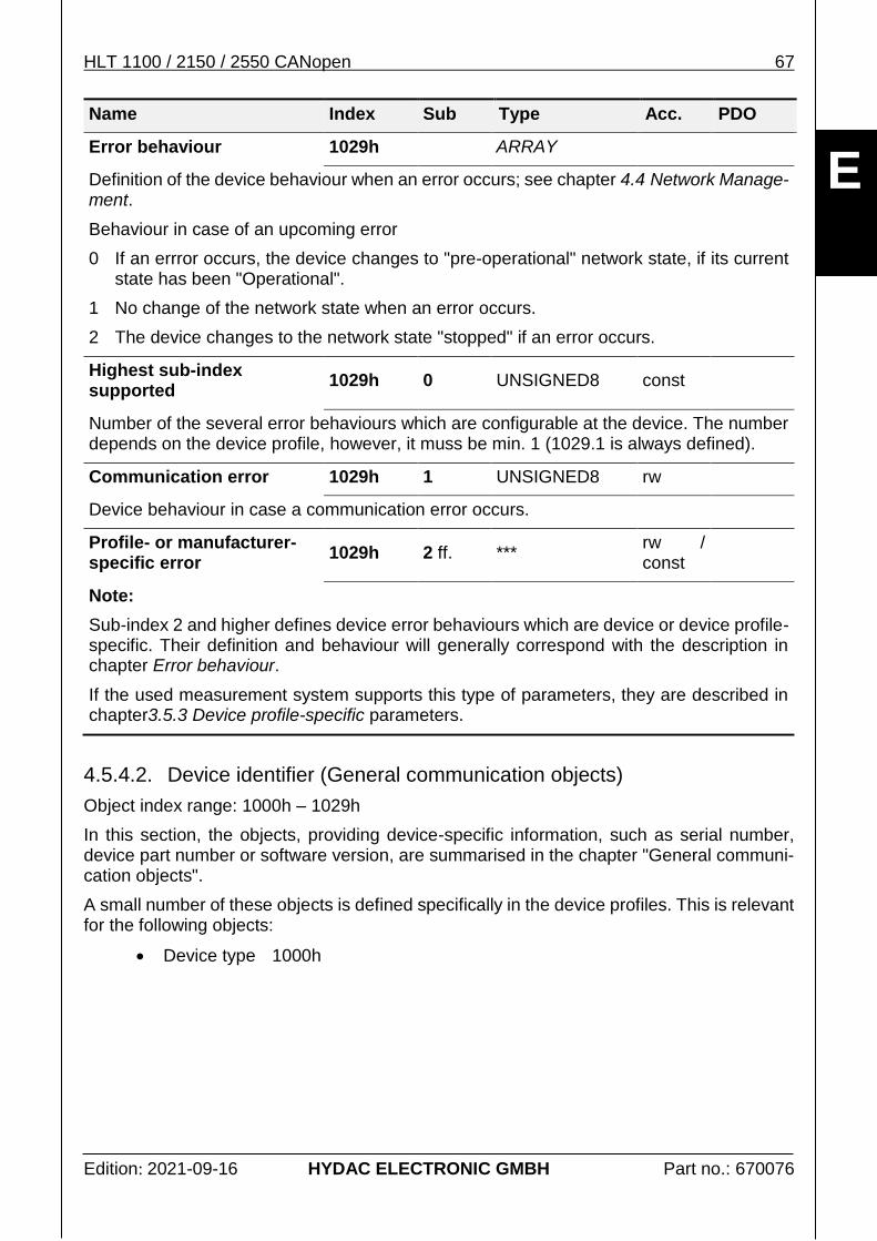
Error behaviour 1029h ARRAY
General; see chapter 4.5.4.1 Error management (General communication objects).
Communication error 1029h 1 UNSIGNED8 rw
Device behaviour in case a communication error occurs.
32 HLT 1100 / 2150 / 2550 CANopen
Edition: 2021-09-16 HYDAC ELECTRONIC GMBH Part no.: 670076
E
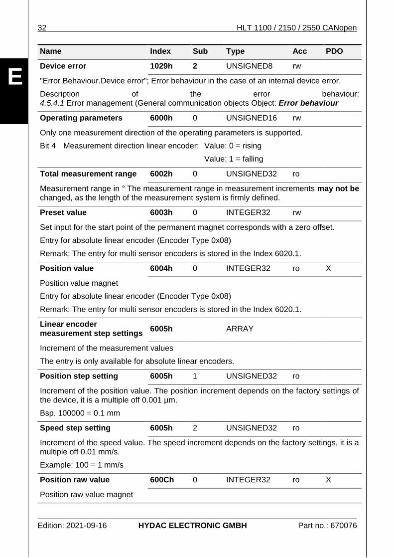
Name Index Sub Type Acc PDO
Device error 1029h 2 UNSIGNED8 rw
"Error Behaviour.Device error"; Error behaviour in the case of an internal device error.
Description of the error behaviour: 4.5.4.1 Error management (General communication objects Object: Error behaviour
Operating parameters 6000h 0 UNSIGNED16 rw
Only one measurement direction of the operating parameters is supported.
Bit 4 Measurement direction linear encoder: Value: 0 = rising
Value: 1 = falling
Total measurement range 6002h 0 UNSIGNED32 ro
Measurement range in ° The measurement range in measurement increments may not be changed, as the length of the measurement system is firmly defined.
Preset value 6003h 0 INTEGER32 rw
Set input for the start point of the permanent magnet corresponds with a zero offset.
Entry for absolute linear encoder (Encoder Type 0x08)
Remark: The entry for multi sensor encoders is stored in the Index 6020.1.
Position value 6004h 0 INTEGER32 ro X
Position value magnet
Entry for absolute linear encoder (Encoder Type 0x08)
Remark: The entry for multi sensor encoders is stored in the Index 6020.1.
Linear encoder measurement step settings
6005h ARRAY
Increment of the measurement values
The entry is only available for absolute linear encoders.
Position step setting 6005h 1 UNSIGNED32 ro
Increment of the position value. The position increment depends on the factory settings of the device, it is a multiple off 0.001 µm.
Bsp. 100000 = 0.1 mm
Speed step setting 6005h 2 UNSIGNED32 ro
Increment of the speed value. The speed increment depends on the factory settings, it is a multiple off 0.01 mm/s.
Example: 100 = 1 mm/s
Position raw value 600Ch 0 INTEGER32 ro X
Position raw value magnet
HLT 1100 / 2150 / 2550 CANopen 33
Edition: 2021-09-16 HYDAC ELECTRONIC GMBH Part no.: 670076
E
Name Index Sub Type Acc PDO
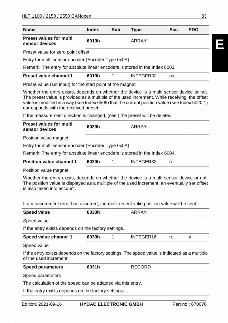
Preset values for multi sensor devices
6010h ARRAY
Preset value for zero point offset
Entry for multi sensor encoder (Encoder Type 0x0A)
Remark: The entry for absolute linear encoders is stored in the Index 6003.
Preset value channel 1 6010h 1 INTEGER32 rw
Preset value (set input) for the start point of the magnet
Whether the entry exists, depends on whether the device is a multi sensor device or not. The preset value is provided as a multiple of the used increment. While receiving, the offset value is modified in a way (see Index 6509) that the current position value (see Index 6020.1) corresponds with the received preset.
If the measurement direction is changed, (see ) the preset will be deleted.
Preset values for multi sensor devices
6020h ARRAY
Position value magnet
Entry for multi sensor encoder (Encoder Type 0x0A)
Remark: The entry for absolute linear encoders is stored in the Index 6004.
Position value channel 1 6020h 1 INTEGER32 ro
Position value magnet
Whether the entry exists, depends on whether the device is a multi sensor device or not. The position value is displayed as a multiple of the used increment, an eventually set offset is also taken into account.
If a measurement error has occurred, the most recent valid position value will be sent.
Speed value 6030h ARRAY
Speed value
If the entry exists depends on the factory settings.
Speed value channel 1 6030h 1 INTEGER16 ro X
Speed value
If the entry exists depends on the factory settings. The speed value is indicated as a multiple of the used increment.
Speed parameters 6031h RECORD
Speed parameters
The calculation of the speed can be adapted via this entry.
If the entry exists depends on the factory settings.
34 HLT 1100 / 2150 / 2550 CANopen
Edition: 2021-09-16 HYDAC ELECTRONIC GMBH Part no.: 670076
E
Name Index Sub Type Acc PDO
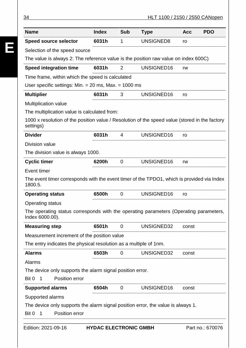
Speed source selector 6031h 1 UNSIGNED8 ro
Selection of the speed source
The value is always 2: The reference value is the position raw value on index 600C)
Speed integration time 6031h 2 UNSIGNED16 rw
Time frame, within which the speed is calculated
User specific settings: Min. = 20 ms, Max. = 1000 ms
Multiplier 6031h 3 UNSIGNED16 ro
Multiplication value
The multiplication value is calculated from:
1000 x resolution of the position value / Resolution of the speed value (stored in the factory settings)
Divider 6031h 4 UNSIGNED16 ro
Division value
The division value is always 1000.
Cyclic timer 6200h 0 UNSIGNED16 rw
Event timer
The event timer corresponds with the event timer of the TPDO1, which is provided via Index 1800.5.
Operating status 6500h 0 UNSIGNED16 ro
Operating status
The operating status corresponds with the operating parameters (Operating parameters, Index 6000.00).
Measuring step 6501h 0 UNSIGNED32 const
Measurement increment of the position value
The entry indicates the physical resolution as a multiple of 1nm.
Alarms 6503h 0 UNSIGNED32 const
Alarms
The device only supports the alarm signal position error.
Bit 0 1 Position error
Supported alarms 6504h 0 UNSIGNED16 const
Supported alarms
The device only supports the alarm signal position error, the value is always 1.
Bit 0 1 Position error
HLT 1100 / 2150 / 2550 CANopen 35
Edition: 2021-09-16 HYDAC ELECTRONIC GMBH Part no.: 670076
E
Name Index Sub Type Acc PDO
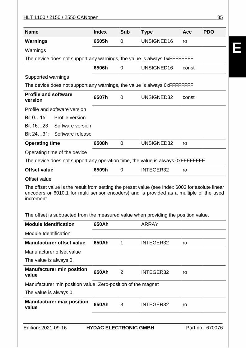
Warnings 6505h 0 UNSIGNED16 ro
Warnings
The device does not support any warnings, the value is always 0xFFFFFFFF
6506h 0 UNSIGNED16 const
Supported warnings
The device does not support any warnings, the value is always 0xFFFFFFFF
Profile and software version
6507h 0 UNSIGNED32 const
Profile and software version
Bit 0…15 Profile version
Bit 16…23 Software version
Bit 24…31: Software release
Operating time 6508h 0 UNSIGNED32 ro
Operating time of the device
The device does not support any operation time, the value is always 0xFFFFFFFF
Offset value 6509h 0 INTEGER32 ro
Offset value
The offset value is the result from setting the preset value (see Index 6003 for asolute linear encoders or 6010.1 for multi sensor encoders) and is provided as a multiple of the used increment.
The offset is subtracted from the measured value when providing the position value.
Module identification 650Ah ARRAY
Module Identification
Manufacturer offset value 650Ah 1 INTEGER32 ro
Manufacturer offset value
The value is always 0.
Manufacturer min position value
650Ah 2 INTEGER32 ro
Manufacturer min position value: Zero-position of the magnet
The value is always 0.
Manufacturer max position value
650Ah 3 INTEGER32 ro
36 HLT 1100 / 2150 / 2550 CANopen
Edition: 2021-09-16 HYDAC ELECTRONIC GMBH Part no.: 670076
E
Name Index Sub Type Acc PDO
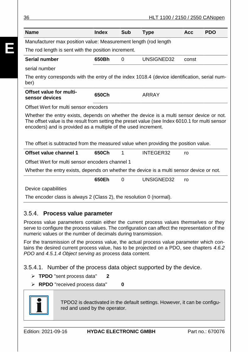
Manufacturer max position value: Measurement length (rod length
The rod length is sent with the position increment.
Serial number 650Bh 0 UNSIGNED32 const
serial number
The entry corresponds with the entry of the index 1018.4 (device identification, serial num-ber)
Offset value for multi-sensor devices
650Ch ARRAY
Offset Wert for multi sensor encoders
Whether the entry exists, depends on whether the device is a multi sensor device or not. The offset value is the result from setting the preset value (see Index 6010.1 for multi sensor encoders) and is provided as a multiple of the used increment.
The offset is subtracted from the measured value when providing the position value.
Offset value channel 1 650Ch 1 INTEGER32 ro
Offset Wert for multi sensor encoders channel 1
Whether the entry exists, depends on whether the device is a multi sensor device or not.
650Eh 0 UNSIGNED32 ro
Device capabilities
The encoder class is always 2 (Class 2), the resolution 0 (normal).
Process value parameter
Process value parameters contain either the current process values themselves or they serve to configure the process values. The configuration can affect the representation of the numeric values or the number of decimals during transmission.
For the transmission of the process value, the actual process value parameter which con-tains the desired current process value, has to be projected on a PDO, see chapters 4.6.2 PDO and 4.5.1.4 Object serving as process data content.
3.5.4.1. Number of the process data object supported by the device.
TPDO "sent process data" 2
RPDO "received process data" 0
TPDO2 is deactivated in the default settings. However, it can be configu-red and used by the operator.
HLT 1100 / 2150 / 2550 CANopen 37
Edition: 2021-09-16 HYDAC ELECTRONIC GMBH Part no.: 670076
E
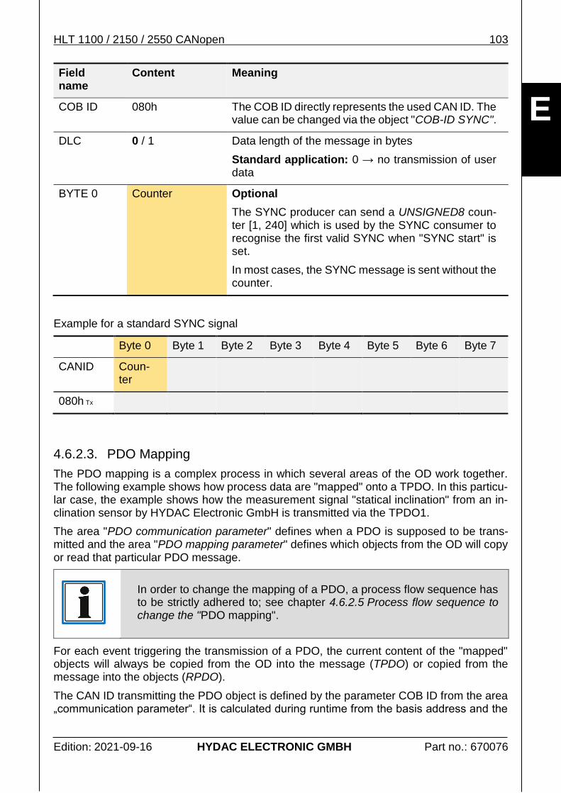
3.5.4.2. Description process value parameters
All process parameters are listed in the chapters 3.5.3 device profile specific parameters or 3.5.5. additional manufacturer-specific measurement channels.
The cross-references are indicated as shown below:
Signal description Reference to the chapter, giving a short explana-tion of the relevant signal. A more detailed description can be found in the related operation manual.
Signal characteristics Refers to the chapter describing the characteris-tics necessary for the evaluation of the measuring range, for instance.
Status information Refers to the chapter which explains the exact structure of a status value belonging to a signal (mainly a BITFIELD).
The HLT 1100 / 2150 / 2550 measurement system series do not provide any additional measurement channels.
They are generally described in chapter 4.5.5.2 Additional manufacturer-specific measure-ment channels.
The actual process values are described in chapter 3.3 Process data.
3.6. Events
Events are information which can occur either spontaneously or time-controlled. They ge-nerally contain additional information on the current device status or of its status change.
Error Messages
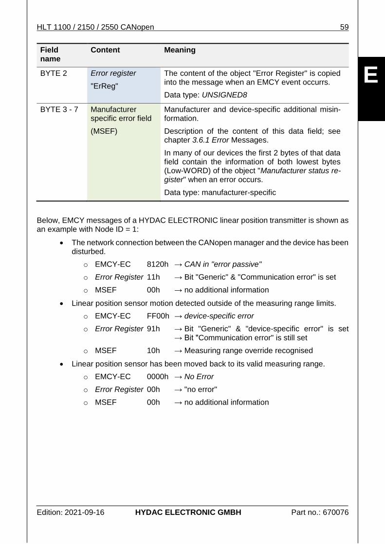
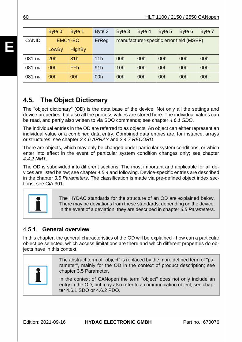
The following table describes the EMCY error numbers (EMCY-EC) supported and sent by the measurement system. The general description of the function principle and the structure of the error messages is explained in chapter 4.4.5 EMCY.
The error register (see 4.4.5 EMCY) transmitted via byte 2 of the EMCY is described below:
General
o Object: Error Register
o Chapter: 4.5.4.1 Error management (General communication objects)
Manufacturer-specific
o Chapter: 3.5.3 Device profile-specific parameters
EMCY-EC Error designation Description
0000h No Error Device reports return to failure-free operation
Manufacturer-specific BITFIELDReset 0
38 HLT 1100 / 2150 / 2550 CANopen
Edition: 2021-09-16 HYDAC ELECTRONIC GMBH Part no.: 670076
E
EMCY-EC Error designation Description
8120h CAN in "error pas-sive"
The device internal CAN controller has chan-ged to the CAN status "error passive".
This error can occur during normal network operation and disappear again; which is an evidence for problems in the network.
Manufacturer-specific Manufacturer status register, low word
8140h Recover form Bus-off The device internal CAN controller has chan-ged to the CAN error status "bus-off".
Evidence for problems in the network.
Manufacturer-specific Manufacturer status register, low word
FF00h device-specific error General device-specific error The occurred er-ror is specified more in detail in the manufac-turer-specific section of the error message.
Manufacturer-specific Manufacturer status register, low word
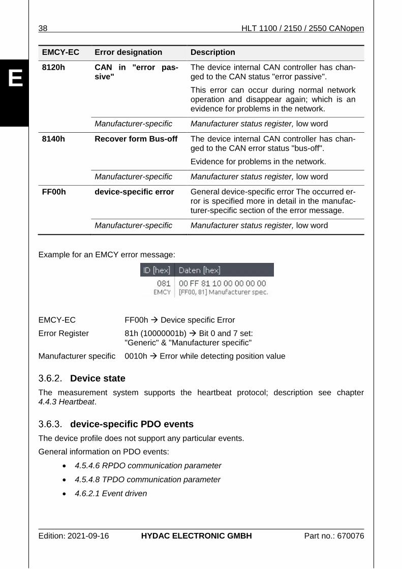
Example for an EMCY error message:
EMCY-EC FF00h Device specific Error
Error Register 81h (10000001b) Bit 0 and 7 set: "Generic" & "Manufacturer specific"
Manufacturer specific 0010h Error while detecting position value
Device state
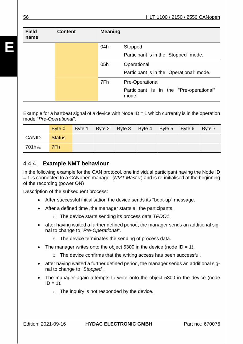
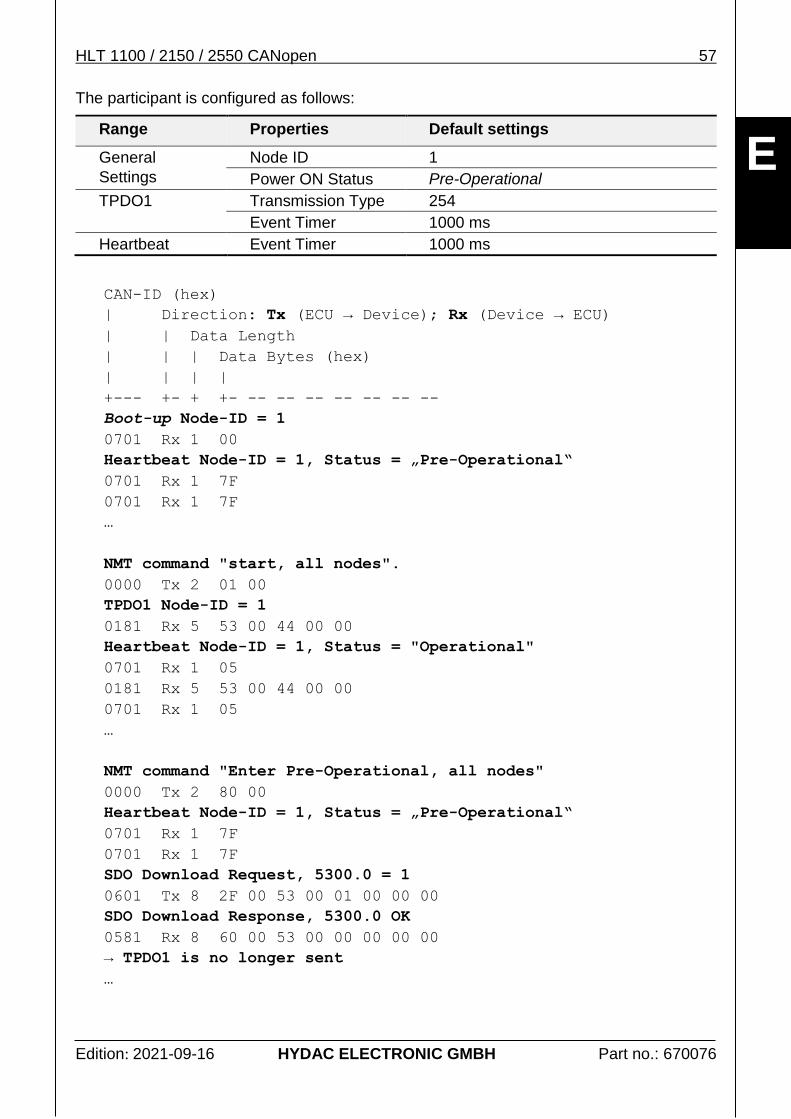
The measurement system supports the heartbeat protocol; description see chapter 4.4.3 Heartbeat.
device-specific PDO events
The device profile does not support any particular events.
General information on PDO events:
4.5.4.6 RPDO communication parameter
4.5.4.8 TPDO communication parameter
4.6.2.1 Event driven
HLT 1100 / 2150 / 2550 CANopen 39
Edition: 2021-09-16 HYDAC ELECTRONIC GMBH Part no.: 670076
E
3.7. Error management
Errors are recognised, administrated and provided by the measurement system in several different ways. On the one hand, there are errors occurring during processing of the process data and on the other hand, there are general device errors. All kinds of errors are provided as parameters (objects in the OD) and can be read out at any time; see chapter 4.6.1 SDO.
Errror behaviour
It depends on the error type and the device configuration of the error behaviour, how the measurement system will react to an occurring error.
With process data errors, the superordinate controller must decide itself, in dependence of the information of the related status signal, what has to be done. The measurement system itself does not change its operation status; see chapter 4.4 Network Management.
With general device errors, such as communication or configuration errors, it is possible to configure, which operation mode the measurement system should take on if an error occurs. The behaviour can be set via the parameter Error behaviour.
Process data error
The process data errors are made available as status signals. The signals should always be evaluated together with their related process values.
The evaluation of the alarms, 3.5.3 Device profile-specific parameters, should always be evaluated together with the process values listed below:
3.3.2 Signal Position
3.2.2 Signal Speed
General error management
In addition with the process-data related status errors, the general error objects are also provided by the measurement system. The characteristics or additions diverging from the general implementation are described in the following.
Supported:
General error register: Error register
Specific error register: Manufacturer status register
Error memory: Pre-defined error field
40 HLT 1100 / 2150 / 2550 CANopen
Edition: 2021-09-16 HYDAC ELECTRONIC GMBH Part no.: 670076
E
Name Index Sub Type Acc PDO
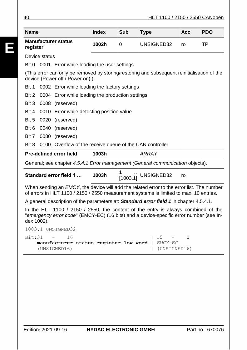
Manufacturer status register
1002h 0 UNSIGNED32 ro TP
Device status
Bit 0 0001 Error while loading the user settings
(This error can only be removed by storing/restoring and subsequent reinitialisation of the device (Power off / Power on).)
Bit 1 0002 Error while loading the factory settings
Bit 2 0004 Error while loading the production settings
Bit 3 0008 (reserved)
Bit 4 0010 Error while detecting position value
Bit 5 0020 (reserved)
Bit 6 0040 (reserved)
Bit 7 0080 (reserved)
Bit 8 0100 Overflow of the receive queue of the CAN controller
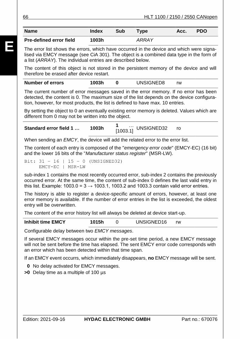
Pre-defined error field 1003h ARRAY
General; see chapter 4.5.4.1 Error management (General communication objects).
Standard error field 1 … 1003h 1 … [1003.1]
UNSIGNED32 ro
When sending an EMCY, the device will add the related error to the error list. The number of errors in HLT 1100 / 2150 / 2550 measurement systems is limited to max. 10 entries.
A general description of the parameters at: Standard error field 1 in chapter 4.5.4.1.
In the HLT 1100 / 2150 / 2550, the content of the entry is always combined of the "emergency error code" (EMCY-EC) (16 bits) and a device-specific error number (see In-dex 1002).
1003.1 UNSIGNED32
Bit:31 – 16 | 15 – 0
manufacturer status register low word | EMCY-EC
(UNSIGNED16) | (UNSIGNED16)
HLT 1100 / 2150 / 2550 CANopen 41
Edition: 2021-09-16 HYDAC ELECTRONIC GMBH Part no.: 670076
E
Error events
Errors causing the change of the general error register (see object: Error register) are also sent as a particular error event; see chapter:
3.6.1 Error Messages
4.4.5 EMCY
3.8. LSS Protocol support
All measurement systems of the HLT 1100 / 2150 / 2550 series support the LSS protocol in the way described in chapter 4.7 Layer setting services (LSS) Protocol.
42 HLT 1100 / 2150 / 2550 CANopen
Edition: 2021-09-16 HYDAC ELECTRONIC GMBH Part no.: 670076
E
4. Protocol description CANopen
Below, please find the description of the CANopen protocol used by the measurement sys-tem. Device-specific settings and behaviour are described in the different subsections in chapter 3 Product interface.
4.1. General overview
The various original documents which have been used for the implementation of the device can be found in the operation manual.
The following description makes no claim to be complete, its only aim is to facilitate work for the user with the CANopen device by HYDAC ELECTRONIC GmbH. In the case of further information should be requi-red, the documents of the CiA, which are referred to in this document and in the related user manual, are applicable.
4.2. Hardware properties
CAN is a Bus system and therefore all network participants will be connected to the same bus cable - parallel operation. On the contrary, the Ethernet, which is usually used in office communication, only connects one participant with one other at one time. For the connection between several participants, additional hardware, i.e. a switch, is necessary. This effort is not necessary using CAN. How the network has to be organised is described in the following chapter 4.2.3 Topology.
CAN mainly has 2 signal lines: CAN-H and CAN-L. Data transmission is performed via these two lines, see chapter 4.2.2 Signal level.
Each network participant is equal in a CAN network, which means that each of the parti-cipants is able and allowed to send messages. If a participant sends, all the others receive the message and decide on their own if it is relevant for them or not.
In the case of a competing access of several participants, CAN will start prioritising mes-sages. This will avoid collisions to occur, as in other systems. The prioritising of messages is carried out via the CAN ID, where the CAN ID 0 has the highest priority, see chapter 4.3.2 Meaning of the CAN ID.
A network participant is not allowed to send, before a message has not been transmitted completely. If two participants start sending at the same time, the participant having the higher priority message will always "win". The structure of a message is described in chapter 4.3.1 Structure principle of a CAN data message.
Transmission of information is bit-oriented in CAN networks and has a recessive and a do-minant signal status. The dominant signal status is enabled to overwrite the recessive one. As one participant, which is sending, will directly read back each written bit, it can also recognise its own message has been overwritten, and will immediately discontinue further data transmission.
The participant who has interrupted transmission, will try to reinitialise its transmission after the higher prioritised message has been sent. In doing this, no messages will be lost.
HLT 1100 / 2150 / 2550 CANopen 43
Edition: 2021-09-16 HYDAC ELECTRONIC GMBH Part no.: 670076
E
Wire connections
CAN does not require any complicated wire connections. For the connection of the network participants one drilled pair of wires should be used. The pair of wires serves for the trans-mission of the signals CAN-H and CAN-L. Non-drilled cables should be avoided. The recom-mended core diameter depends on the length and has an average between 0.34 and 0.6 mm2.
Almost all CAN connections provide an additional CAN_GND und CAN_SHLD. CAN_GND corresponds with a signal mass and can be used to bring the reference potential of the network participants to one common level. CAN_SHLD serves as a connecction of a shiel-ding for the signal line. Generally, the CAN signal lines do not require any shielding.
Potential loss between network participants should be avoided. They may damage the wire connections or the electronic unit. The connection CAN_GND is not intended for equipotential bonding.
Signal level
For the transmission, a symmetric voltage signal is used. This signal type has no direct reference with a signal mass, but only the voltage difference between both signal lines will be evaluated. This type of signal transmission has significant benefits in the case of inter-fering signals, as these will affect both signal lines equally and will be excluded at the sub-traction.
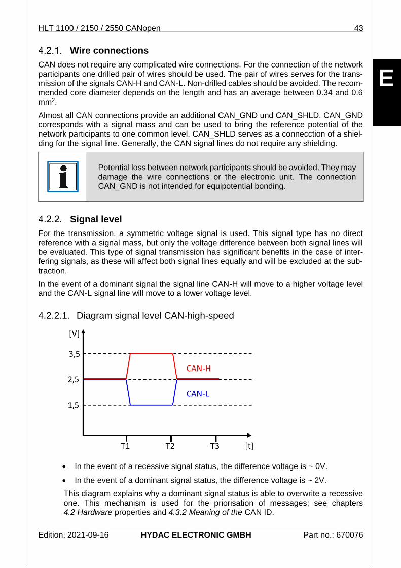
In the event of a dominant signal the signal line CAN-H will move to a higher voltage level and the CAN-L signal line will move to a lower voltage level.
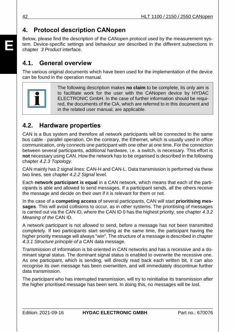
4.2.2.1. Diagram signal level CAN-high-speed
In the event of a recessive signal status, the difference voltage is ~ 0V.
In the event of a dominant signal status, the difference voltage is ~ 2V.
This diagram explains why a dominant signal status is able to overwrite a recessive one. This mechanism is used for the priorisation of messages; see chapters 4.2 Hardware properties and 4.3.2 Meaning of the CAN ID.
44 HLT 1100 / 2150 / 2550 CANopen
Edition: 2021-09-16 HYDAC ELECTRONIC GMBH Part no.: 670076
E
4.2.2.2. Diagram signal logic
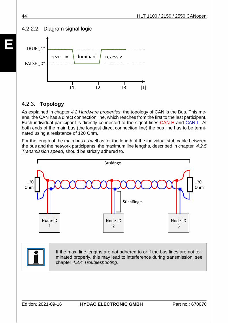
Topology
As explained in chapter 4.2 Hardware properties, the topology of CAN is the Bus. This me-ans, the CAN has a direct connection line, which reaches from the first to the last participant. Each individual participant is directly connected to the signal lines CAN-H and CAN-L. At both ends of the main bus (the longest direct connection line) the bus line has to be termi-nated using a resistance of 120 Ohm.
For the length of the main bus as well as for the length of the individual stub cable between the bus and the network participants, the maximum line lengths, described in chapter 4.2.5 Transmission speed, should be strictly adhered to.
If the max. line lengths are not adhered to or if the bus lines are not ter-minated properly, this may lead to interference during transmission, see chapter 4.3.4 Troubleshooting.
HLT 1100 / 2150 / 2550 CANopen 45
Edition: 2021-09-16 HYDAC ELECTRONIC GMBH Part no.: 670076
E
A CAN network can usually include up to 32 network participants.
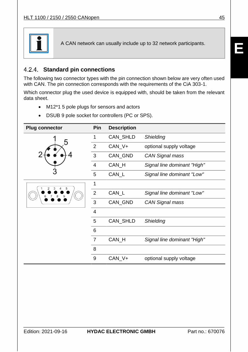
Standard pin connections
The following two connector types with the pin connection shown below are very often used with CAN. The pin connection corresponds with the requirements of the CiA 303-1.
Which connector plug the used device is equipped with, should be taken from the relevant data sheet.
M12*1 5 pole plugs for sensors and actors
DSUB 9 pole socket for controllers (PC or SPS).
Plug connector Pin Description
1 CAN_SHLD Shielding
2 CAN_V+ optional supply voltage
3 CAN_GND CAN Signal mass
4 CAN_H Signal line dominant "High"
5 CAN_L Signal line dominant "Low"
1
2 CAN_L Signal line dominant "Low"
3 CAN_GND CAN Signal mass
4
5 CAN_SHLD Shielding
6
7 CAN_H Signal line dominant "High"
8
9 CAN_V+ optional supply voltage
46 HLT 1100 / 2150 / 2550 CANopen
Edition: 2021-09-16 HYDAC ELECTRONIC GMBH Part no.: 670076
E
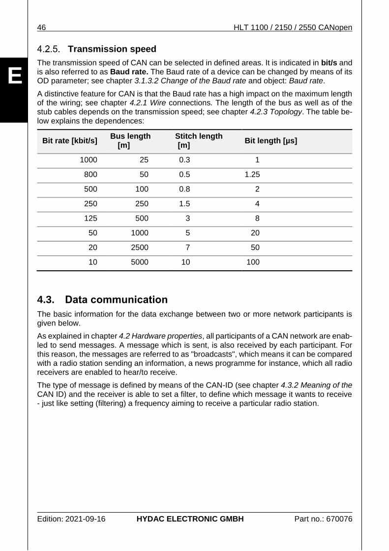
Transmission speed
The transmission speed of CAN can be selected in defined areas. It is indicated in bit/s and is also referred to as Baud rate. The Baud rate of a device can be changed by means of its OD parameter; see chapter 3.1.3.2 Change of the Baud rate and object: Baud rate.
A distinctive feature for CAN is that the Baud rate has a high impact on the maximum length of the wiring; see chapter 4.2.1 Wire connections. The length of the bus as well as of the stub cables depends on the transmission speed; see chapter 4.2.3 Topology. The table be-low explains the dependences:
Bit rate [kbit/s] Bus length
[m] Stitch length [m]
Bit length [µs]
1000 25 0.3 1
800 50 0.5 1.25
500 100 0.8 2
250 250 1.5 4
125 500 3 8
50 1000 5 20
20 2500 7 50
10 5000 10 100
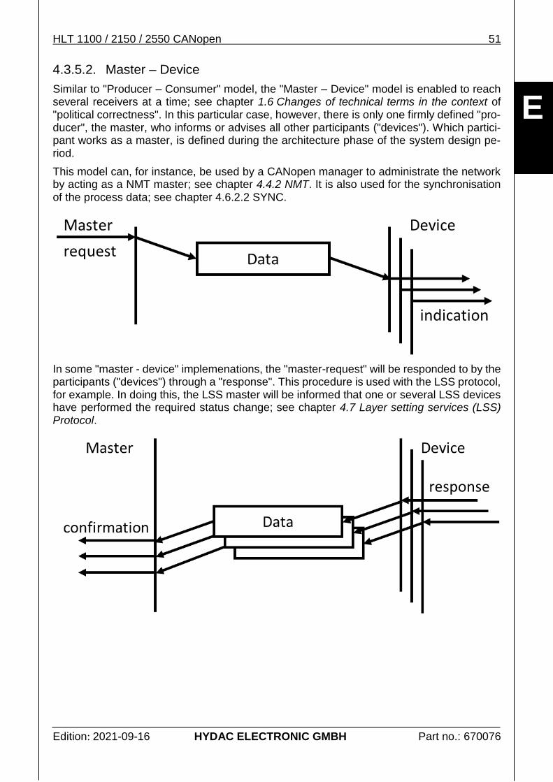
4.3. Data communication
The basic information for the data exchange between two or more network participants is given below.
As explained in chapter 4.2 Hardware properties, all participants of a CAN network are enab-led to send messages. A message which is sent, is also received by each participant. For this reason, the messages are referred to as "broadcasts", which means it can be compared with a radio station sending an information, a news programme for instance, which all radio receivers are enabled to hear/to receive.
The type of message is defined by means of the CAN-ID (see chapter 4.3.2 Meaning of the CAN ID) and the receiver is able to set a filter, to define which message it wants to receive - just like setting (filtering) a frequency aiming to receive a particular radio station.
HLT 1100 / 2150 / 2550 CANopen 47
Edition: 2021-09-16 HYDAC ELECTRONIC GMBH Part no.: 670076
E
Structure principle of a CAN data message
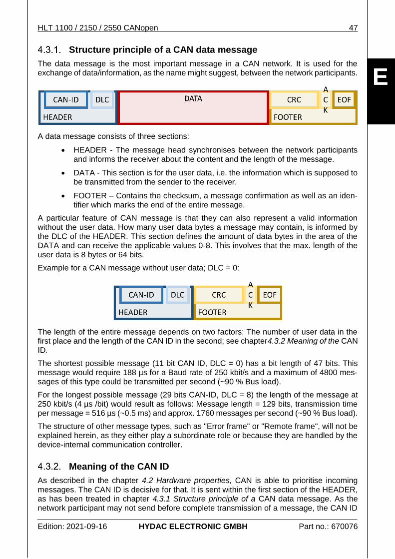
The data message is the most important message in a CAN network. It is used for the exchange of data/information, as the name might suggest, between the network participants.
A data message consists of three sections:
HEADER - The message head synchronises between the network participants and informs the receiver about the content and the length of the message.
DATA - This section is for the user data, i.e. the information which is supposed to be transmitted from the sender to the receiver.
FOOTER – Contains the checksum, a message confirmation as well as an iden-tifier which marks the end of the entire message.
A particular feature of CAN message is that they can also represent a valid information without the user data. How many user data bytes a message may contain, is informed by the DLC of the HEADER. This section defines the amount of data bytes in the area of the DATA and can receive the applicable values 0-8. This involves that the max. length of the user data is 8 bytes or 64 bits.
Example for a CAN message without user data; DLC = 0:
The length of the entire message depends on two factors: The number of user data in the first place and the length of the CAN ID in the second; see chapter4.3.2 Meaning of the CAN ID.
The shortest possible message (11 bit CAN ID, DLC = 0) has a bit length of 47 bits. This message would require 188 µs for a Baud rate of 250 kbit/s and a maximum of 4800 mes-sages of this type could be transmitted per second (~90 % Bus load).
For the longest possible message (29 bits CAN-ID, DLC = 8) the length of the message at 250 kbit/s (4 µs /bit) would result as follows: Message length = 129 bits, transmission time per message = 516 µs (~0.5 ms) and approx. 1760 messages per second (~90 % Bus load).
The structure of other message types, such as "Error frame" or "Remote frame", will not be explained herein, as they either play a subordinate role or because they are handled by the device-internal communication controller.
Meaning of the CAN ID
As described in the chapter 4.2 Hardware properties, CAN is able to prioritise incoming messages. The CAN ID is decisive for that. It is sent within the first section of the HEADER, as has been treated in chapter 4.3.1 Structure principle of a CAN data message. As the network participant may not send before complete transmission of a message, the CAN ID
48 HLT 1100 / 2150 / 2550 CANopen
Edition: 2021-09-16 HYDAC ELECTRONIC GMBH Part no.: 670076
E
can be used to prioritise, applying the mechanism of the recessive and the dominant signal statuses; see chapter 4.2.2 Signal level.
The priority of a message depends on the value of the CAN ID.
The lower the CAN ID, the higher the priority of the message.
CAN ID = 0 has the highest possible priority.
CAN does not know any direct address of the participants. The CAN ID defines, which im-portance a message has, thus, the CAN ID 0 identifies the NMT message for example - the network management; see chapter 4.4 Network Management.
Whereas CANopen takes the opportunity to structure the CAN ID and to combine the im-portance (service ID) with the participant's address; i.e. the CAN ID of the first process data object is defined by 180h + Node ID.
In CANopen, the syonym COB ID is often used instead of CAN ID. The COB ID can either be the CAN ID itself, or the combination of the basic CAN ID and the Node ID, which develops to become a concrete CAN ID during the life time of the device; i. e. object COB-ID emergency mes-sage.
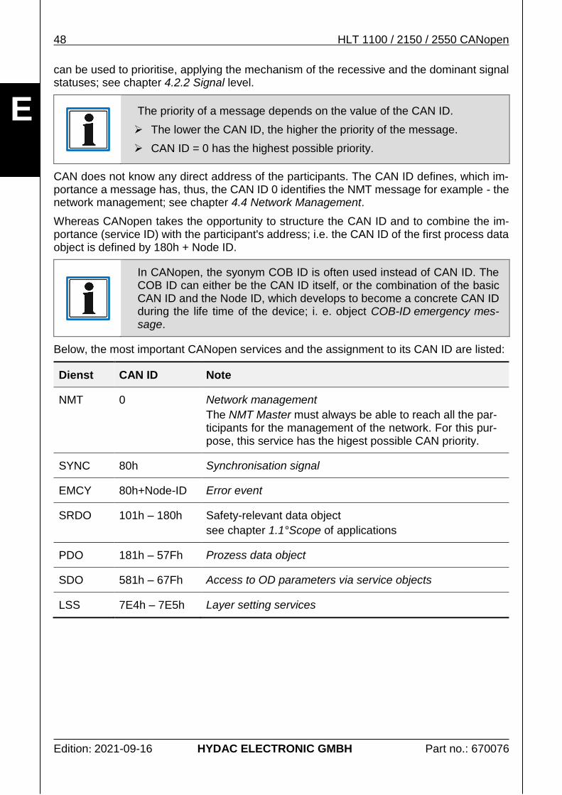
Below, the most important CANopen services and the assignment to its CAN ID are listed:
Dienst CAN ID Note
NMT 0 Network management
The NMT Master must always be able to reach all the par-ticipants for the management of the network. For this pur-pose, this service has the higest possible CAN priority.
SYNC 80h Synchronisation signal
EMCY 80h+Node-ID Error event
SRDO 101h – 180h Safety-relevant data object
see chapter 1.1°Scope of applications
PDO 181h – 57Fh Prozess data object
SDO 581h – 67Fh Access to OD parameters via service objects
LSS 7E4h – 7E5h Layer setting services
HLT 1100 / 2150 / 2550 CANopen 49
Edition: 2021-09-16 HYDAC ELECTRONIC GMBH Part no.: 670076
E
Meaning of the Node ID
As explained in chapter4.3.2 Meaning of the CAN ID, no particular network participant can be addressed directly using exclusively the CAN ID. As it is, however, vital in automatisation to address one particular participant in the network, the Node ID has been generated to become the address of the participant.
The Node Id of a participant always has to be clear within the network, which means, it may not exist more than once.
The valid value range of the Node ID is 01h to 7Fh (1d to 127d), i. e. there can only be max. 127 different participants within one CANopen network.
There are different ways to change the Node ID:
Default settings: 3.1.1 CANopen default settings
3.1.3.1 Changing the device address (node ID)
4.7 Layer setting services (LSS) Protocol
Object: Node ID
Troubleshooting
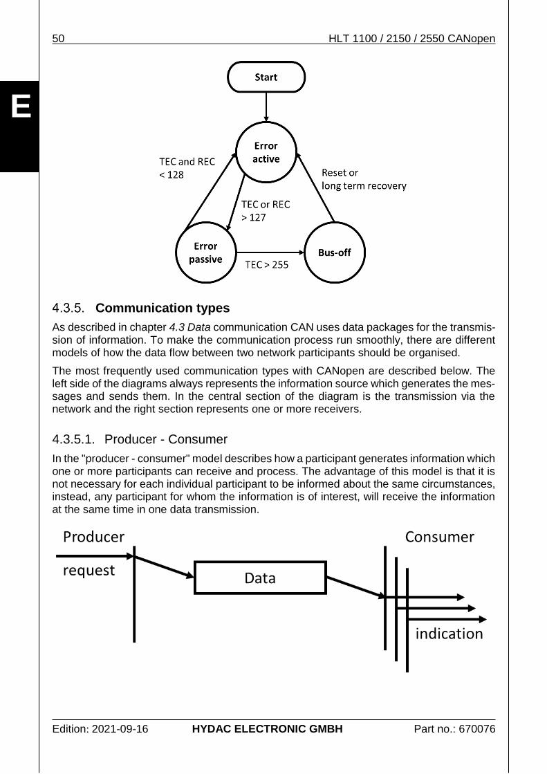
CAN has its own error management, which is composed of 3 different error statuses. The change between the different error statuses is managed via internal error counters (TEC: Send, REC: receive error counter). A more detailed description of the bus behaviour can be found in the ISO 11898-1.
If a participant recognises an error when sending, or if one of the recipients reports a trans-mission error by means of sending back a particular error message, the sender will repeat sending its failed message as soon as possible.
Error active
Is the "normal" operation condition of a network participant. In this condition, a parti-cipant is able to send messages as well as to inform other participants actively about communication errors which it has detected.
Error passive
The participant is in a "temporary" error condition. In this condition, messages can still be sent and received. After sending a message, however, the participant will maintain a certain delay before sending the next message. This gives the partici-pants, which do not show any interference the opportunity to send their messages earlier. This mechanism is supposed to reduce network traffic if there is one inter-fering participant.
Bus-off
The participant is in an error condition. It is neither able to send nor to acknowledge any messages. This state can only be left if the participant is actively reset or if no errors have occurred at the bus within a certain delay. After their return, the error counters have been reset and the participant has returned to the "error active" status.
50 HLT 1100 / 2150 / 2550 CANopen
Edition: 2021-09-16 HYDAC ELECTRONIC GMBH Part no.: 670076
E
Communication types
As described in chapter 4.3 Data communication CAN uses data packages for the transmis-sion of information. To make the communication process run smoothly, there are different models of how the data flow between two network participants should be organised.
The most frequently used communication types with CANopen are described below. The left side of the diagrams always represents the information source which generates the mes-sages and sends them. In the central section of the diagram is the transmission via the network and the right section represents one or more receivers.
4.3.5.1. Producer - Consumer
In the "producer - consumer" model describes how a participant generates information which one or more participants can receive and process. The advantage of this model is that it is not necessary for each individual participant to be informed about the same circumstances, instead, any participant for whom the information is of interest, will receive the information at the same time in one data transmission.
HLT 1100 / 2150 / 2550 CANopen 51
Edition: 2021-09-16 HYDAC ELECTRONIC GMBH Part no.: 670076
E
4.3.5.2. Master – Device
Similar to "Producer – Consumer" model, the "Master – Device" model is enabled to reach several receivers at a time; see chapter 1.6 Changes of technical terms in the context of "political correctness". In this particular case, however, there is only one firmly defined "pro-ducer", the master, who informs or advises all other participants ("devices"). Which partici-pant works as a master, is defined during the architecture phase of the system design pe-riod.
This model can, for instance, be used by a CANopen manager to administrate the network by acting as a NMT master; see chapter 4.4.2 NMT. It is also used for the synchronisation of the process data; see chapter 4.6.2.2 SYNC.
In some "master - device" implemenations, the "master-request" will be responded to by the participants ("devices") through a "response". This procedure is used with the LSS protocol, for example. In doing this, the LSS master will be informed that one or several LSS devices have performed the required status change; see chapter 4.7 Layer setting services (LSS) Protocol.
52 HLT 1100 / 2150 / 2550 CANopen
Edition: 2021-09-16 HYDAC ELECTRONIC GMBH Part no.: 670076
E
4.3.5.3. Request – Response / Client – Server
The "Request – Response" model enables one particular participant to inquire an informa-tion from another particular participant. The client communicates to the recipient (server), usually by means of data from the data package, what information it wants to inquire (data request). Theoretically, such a request may also consist of just a message without the data, see chapter 4.3.1 Structure principle of a CAN data message DLC = 0.
The recipient takes on the function of a server, administrating a pool of data or services, which can be requested directly from that pool by a client. An example from our daily practice could also be requesting a website on the internet by entering an URL address into the "internet browser". The request is comparable with the entry of the address and the response is the page that is subsequently loaded and displayed.
From the point of view of CANopen, this type of communication is used when accessing the OD, see chapters 4.5 The Object Dictionary and 4.6.1 SDO.
4.4. Network Management
In automatisation of machines, it is crucial to keep the communication under control. The CANopen manager is responsible for this task. This manager is usually represented by a superordinate control, e. g. a PLC or a mobile control unit.
There are several different operating conditions which can be taken on by the different par-ticipants, controlled by the CANopen manager. Depending on the operating condition of a participant, it can provide (or not provide) certain services autonomousl;, see chapter 4.4.1 Overview network conditions. The administration of the network condition is carried out via the service of "network control"; see chapter 4.4.2 NMT.
The two most important conditions are:
Pre-Operational
This condition serves to parameterise a participant suitable for a specific application, see chapters 4.6.1 SDO and 4.5 The Object Dictionary. In addition, further services are carried out, such as for example: 4.4.3 Heartbeat.
A participant takes on that condition automatically after start-up and usually remains in this state, until a command for status change has been received explicitly. The participant's start-up behaviou can be controlled via the object "NMT startup".
HLT 1100 / 2150 / 2550 CANopen 53
Edition: 2021-09-16 HYDAC ELECTRONIC GMBH Part no.: 670076
E
Important note: In this state, no process data can be received or sent.
Operational
The condition of "operational" is the normal operating condition of a participant. Al-most all CANopen communication services can be used. This condition only enables the participants to receive and to process the process data and to generate and send their own process data, see chapters 4.6.2 PDO and 4.6.3 SRDO.
In this operating condition, the parameters can also be read, however, the option of changing parameters is limited; see 4.6.2.3 PDO Mapping.
Overview network conditions
In general, the conditions are subdivided into the categories: initialisation and operation of a participant. The initialisation phase is gone through automatically after applying the supply voltage. After successful initialisation, the participant sends a "Boot-Up" message by means of which the Node ID of a participant can be identified; see also chapter 4.4.3 Heartbeat.
After successful initialisation, there are 3 different operating conditions available. The most important conditions "pre-operational" and "operational" were already explained in chapter 4.4 Network Management.
In the "stopped" condition, only the network (see 4.4.2 NMT) and error services (see 4.4.3 Heartbeat) are active, whereas all the other services are not available.
The following table provides an overview of what services are available in the different ope-rating conditions:
54 HLT 1100 / 2150 / 2550 CANopen
Edition: 2021-09-16 HYDAC ELECTRONIC GMBH Part no.: 670076
E
Service ID Pre-Operational Operational Stopped
PDO X
SRDO X
SDO X X
SYNC X X
TIME X X
EMCY X X
Heartbeat X X X
LSS X X
NMT X X X
NMT
The administration of the network conditions is carried out via the "network control" service. For this purpose, there is a defined NMT master which gives the command (using a NMT message) to each individual participant (device) to change their state, NMT = Network Ma-nagement.
The "Network Control" service is performed via the Master – Devicecommunication model. The CANopen Manager (controller) generally takes over the role of the NMT Master
As this service makes the decisions on the interaction between the participants in the net-work, it has been assigned the most important priority; see chapter 4.3.2 Meaning of the CAN ID and 4.3.1 Structure principle of a CAN data message.
The NMT message has a data length of 2 bytes, each of which has a particular signification which is documented below.
Field name
Content Meaning
CAN ID 0 CAN ID of the message
DLC 2 Data length of the message in bytes
BYTE 0 Command 01h Start node
Participant is supposed to switch to "Ope-rational" state.
02h Stop node
Participant is supposed to switch to "Stop-ped" state.
80h Enter Pre-Operational
Participant is supposed to switch to "Pre-operational" state.
HLT 1100 / 2150 / 2550 CANopen 55
Edition: 2021-09-16 HYDAC ELECTRONIC GMBH Part no.: 670076
E
Field name
Content Meaning
81h Reset node
Participant is supposed to be reinitialised.
82h Reset communication
Participant is supposed to restart its com-munication layer.
BYTE 1 Node ID 0d Message is being processed by all partici-pants.
1-127d Node ID of the participant to be changed.
Example for a signal from the NMT Master telling all network participants to change to ope-rating state "Operational" → NMT "Start all nodes".
The heartbeat protocol serves one participant to inform all the participants within the network about its current opterating state.
This service is implemented according to the 4.3.5.1 Producer - Consumer model.
The message needs to be activated explicitly and is sent on a cyclical basis. Via the object "Producer heartbeat time" the heartbeat can be activated and the repeat rate can be confi-gured.
Should the heartbeat consumer report the absence of a heartbeat message, it will inform its superordinate application software about this event. The application should then react in the appropriate way.
The message has a data length of one byte, which reports the current state of the participant.
Field name
Content Meaning
COB ID 700h + Node-ID CAN ID of the message der Nachricht errechnet im Betrieb aus der Basis CAN-ID und der Node-ID des Teilnehmers.
DLC 1 Data length of the message in bytes
BYTE 0 Status 00h Boot-up
The participant reports a system start.
56 HLT 1100 / 2150 / 2550 CANopen
Edition: 2021-09-16 HYDAC ELECTRONIC GMBH Part no.: 670076
E
Field name
Content Meaning
04h Stopped
Participant is in the "Stopped" mode.
05h Operational
Participant is in the "Operational" mode.
7Fh Pre-Operational
Participant is in the "Pre-operational" mode.
Example for a hartbeat signal of a device with Node ID = 1 which currently is in the operation mode "Pre-Operational".
In the following example for the CAN protocol, one individual participant having the Node ID = 1 is connected to a CANopen manager (NMT Master) and is re-initialised at the beginning of the recording (power ON)
Description of the subsequent process:
After successful initialisation the device sends its "boot-up" message.
After a defined time ,the manager starts all the participants.
o The device starts sending its process data TPDO1.
after having waited a further defined period, the manager sends an additional sig-nal to change to "Pre-Operational".
o The device terminates the sending of process data.
The manager writes onto the object 5300 in the device (node ID = 1).
o The device confirms that the writing access has been successful.
after having waited a further defined period, the manager sends an additional sig-nal to change to "Stopped".
The manager again attempts to write onto the object 5300 in the device (node ID = 1).
o The inquiry is not responded by the device.
HLT 1100 / 2150 / 2550 CANopen 57
Edition: 2021-09-16 HYDAC ELECTRONIC GMBH Part no.: 670076
E
The participant is configured as follows:
Range Properties Default settings
General
Settings
Node ID 1
Power ON Status Pre-Operational
TPDO1 Transmission Type 254
Event Timer 1000 ms
Heartbeat Event Timer 1000 ms
CAN-ID (hex)
| Direction: Tx (ECU → Device); Rx (Device → ECU)
| | Data Length
| | | Data Bytes (hex)
| | | |
+--- +- + +- -- -- -- -- -- -- --
Boot-up Node-ID = 1
0701 Rx 1 00
Heartbeat Node-ID = 1, Status = „Pre-Operational“
0701 Rx 1 7F
0701 Rx 1 7F
…
NMT command "start, all nodes".
0000 Tx 2 01 00
TPDO1 Node-ID = 1
0181 Rx 5 53 00 44 00 00
Heartbeat Node-ID = 1, Status = "Operational"
0701 Rx 1 05
0181 Rx 5 53 00 44 00 00
0701 Rx 1 05
…
NMT command "Enter Pre-Operational, all nodes"
0000 Tx 2 80 00
Heartbeat Node-ID = 1, Status = „Pre-Operational“
0701 Rx 1 7F
0701 Rx 1 7F
SDO Download Request, 5300.0 = 1
0601 Tx 8 2F 00 53 00 01 00 00 00
SDO Download Response, 5300.0 OK
0581 Rx 8 60 00 53 00 00 00 00 00
→ TPDO1 is no longer sent
…
58 HLT 1100 / 2150 / 2550 CANopen
Edition: 2021-09-16 HYDAC ELECTRONIC GMBH Part no.: 670076
E
NMT command "stop, all nodes".
0000 Tx 2 02 00
Heartbeat Node-ID = 1, Status = "Stopped"
0701 Rx 1 04
0701 Rx 1 04
SDO Download Request, 5300.0 = 1
0601 Tx 8 2F 00 53 00 01 00 00 00
→ Not received any SDO Download Response; Node 1 in "stopped"
0701 Rx 1 04
EMCY
By means of EMCY messages, the device can inform other participants in the network when it has detected an error itself.
EMCY messages are implemented according to the "producer/consumer" model; see chap-ter 4.3.5.1 Producer - Consumer.
An EMCY message is sent only once. Sending is performed, whenever an error has been recognised in the device.
Has the error been recognised for the first time, the corresponding bit of the error register (see object "Error register") is set. If all the bits in the error register have been erased, the EMCY message with the error number 0000h is sent. This particular EMCY serves as an identifier in order to signalise that all error states have been set back and that the device has returned to trouble-free operation.
An EMCY message has a length of 8 bytes. The first bytes contain the "emergency error code" (EMCY-EC) (2 bytes), specified in the CiA 301 and the Error register (1 byte) of the device. The remaining 5 bytes are manufacturer and also mostly device-specific.
In order to avoid an accumulation of EMCY messages (for instance in the event of a faulty CANbus connection), a minimum waiting delay between two EMCY messages can be defi-ned "Inhibit time EMCY" .
How the device should behave when an error has occurred, can be definded via the object "Error behaviour". An action might be the change of the activated operation mode; see chapter 4.4.1 Overview network conditions.
Field name
Content Meaning
COB ID 80h + Node-ID CAN ID of the message is calculated during opera-tion from the basic CAN ID and the Node ID of the participant.
DLC 8 Data length of the message in bytes
BYTE 0, 1 emergency error code
"EMCY-EC"
Error number of the EMCY event The error numbers supported by the device are described in chapter 3.6.1 Error Messages.
Data type: UNSIGNED16
HLT 1100 / 2150 / 2550 CANopen 59
Edition: 2021-09-16 HYDAC ELECTRONIC GMBH Part no.: 670076
E
Field name
Content Meaning
BYTE 2 Error register
"ErReg"
The content of the object "Error Register" is copied into the message when an EMCY event occurrs.
Data type: UNSIGNED8
BYTE 3 - 7 Manufacturer specific error field
(MSEF)
Manufacturer and device-specific additional misin-formation.
Description of the content of this data field; see chapter 3.6.1 Error Messages.
In many of our devices the first 2 bytes of that data field contain the information of both lowest bytes (Low-WORD) of the object "Manufacturer status re-gister" when an error occurs.
Data type: manufacturer-specific
Below, EMCY messages of a HYDAC ELECTRONIC linear position transmitter is shown as an example with Node ID = 1:
The network connection between the CANopen manager and the device has been disturbed.
o EMCY-EC 8120h → CAN in "error passive"
o Error Register 11h → Bit "Generic" & "Communication error" is set
o MSEF 00h → no additional information
Linear position sensor motion detected outside of the measuring range limits.
o EMCY-EC FF00h → device-specific error
o Error Register 91h → Bit "Generic" & "device-specific error" is set → Bit "Communication error" is still set
o MSEF 10h → Measuring range override recognised
Linear position sensor has been moved back to its valid measuring range.
o EMCY-EC 0000h → No Error
o Error Register 00h → "no error"
o MSEF 00h → no additional information
60 HLT 1100 / 2150 / 2550 CANopen
Edition: 2021-09-16 HYDAC ELECTRONIC GMBH Part no.: 670076
CANID EMCY-EC ErReg manufacturer-specific error field (MSEF)
LowBy HighBy
081h Rx 20h 81h 11h 00h 00h 00h 00h 00h
081h Rx 00h FFh 91h 10h 00h 00h 00h 00h
081h Rx 00h 00h 00h 00h 00h 00h 00h 00h
4.5. The Object Dictionary
The "object dictionary" (OD) is the data base of the device. Not only all the settings and device properties, but also all the process values are stored here. The individual values can be read, and partly also written to via SDO commands; see chapter 4.6.1 SDO.
The individual entries in the OD are referred to as objects. An object can either represent an individual value or a combined data entry. Combined data entries are, for instance, arrays or structures; see chapter 2.4.6 ARRAY and 2.4.7 RECORD.
There are objects, which may only be changed under particular system conditions, or which enter into effect in the event of particular system condition changes only; see chapter 4.4.2 NMT.
The OD is subdivided into different sections. The most important and applicable for all de-vices are listed below; see chapter 4.5.4 and following. Device-specific entries are described in the chapter 3.5 Parameters. The classification is made via pre-defined object index sec-tions, see CiA 301.
The HYDAC standards for the structure of an OD are explained below. There may be deviations from these standards, depending on the device. In the event of a deviation, they are described in chapter 3.5 Parameters.
General overview
In this chapter, the general characteristics of the OD will be explained - how can a particular object be selected, which access limitations are there and which different properties do ob-jects have in this context.
The abstract term of "object" is replaced by the more defined term of "pa-rameter", mainly for the OD in the context of product description; see chapter 3.5 Parameter.
In the context of CANopen the term "object" does not only include an entry in the OD, but may also refer to a communication object; see chap-ter 4.6.1 SDO or 4.6.2 PDO.
HLT 1100 / 2150 / 2550 CANopen 61
Edition: 2021-09-16 HYDAC ELECTRONIC GMBH Part no.: 670076
E
4.5.1.1. Addressing
Each entry in the OD is addressed via an object index. The index value identifies the con-crete object. If the object represents the combined data type, the index will be subdivided into further sub-indices. A specific value from this type of structure will therefore be addressed via the indication of the index and the sub-index.
The notation of an object index will always be represented by hexade-cimals, whereas the sub-index will be represented by decimals.
At first, the index of the main object will be indicated and divided by a "." the index of the relevant sub-object. Addressing a particular object will, thus, be represented as follows:
<index>.<subindex>
1018.2 → Identity object.Product code = 928037 s. 4.5.3 OD Example
When accessing a single object in the OD, the sub-index 0 always has to be indicated addi-tionally for the addressing; see chapter 4.6.1 SDO.
1005.0 → COB-ID SYNC = 128 (80h)
In one device, it is not required to have all the indices continuously and addressable. Gaps are usual in the OD. When accessing a non-defined object, the related error message will be issued.
4.5.1.2. Object access types
Also referred to as "access" or "acc." below.
ro read only Object is readable only, the content may change during runtime.
rw read write Object can be read an written to, the content can also be changed during runtime by the device; i.e. object "Producer heartbeat time".
rww read write, process write Object can be read and written to. If the object is marked as "mappable" at the same time, it can only be mapped to a PDO for writing onto it, i.e. a RPDO.
rww read write, process read Object can be read and written to. If the object is marked as "mappable" at the same time, it can only be mapped to a PDO for reading, i.e. a TPDO.
wo write only The object can only be written but cannot be read.
const The object can only be read, the content does not change during runtime.
62 HLT 1100 / 2150 / 2550 CANopen
Edition: 2021-09-16 HYDAC ELECTRONIC GMBH Part no.: 670076
E
Changes to the object are always performed in the volatile device me-mory (RAM). In order to permanently save changes, a storing function has to be activated; see chapter 4.5.1.3 Objects serving as functions.
4.5.1.3. Objects serving as functions
Some objects are similar with function calls. For calling up a function which is assigned to an object, the object is usually assigned a particular activation value. The writing process consequently provokes the assigned function.
An important example for this is the feature "Store parameters", which should be activated for the permanent storage of object changes.
4.5.1.4. Object serving as process data content
Some entries in the OD can be used for the transmission via a process value (PDO). The main advantage is that, doing this, the content of the object does not have to be requested explicitly via a SDO command any more, but is permanently available in the context of pro-cess data transmission.
The object properties "mappable" defines that the content of the object can be transmitted via a PDO; see chapters 4.6.2 PDO and 4.6.2.3 PDO Mapping.
In the different object tables, all the objects which are able to be transmitted as a process value, are marked in the "PDO" column, i.e. object "Error register.
TP Objekt can be mapped on a TPDO (Transmit).
RP Objekt can be mapped on a RPDO (Receive).
HLT 1100 / 2150 / 2550 CANopen 63
Edition: 2021-09-16 HYDAC ELECTRONIC GMBH Part no.: 670076
E
Overview OD areas
The highlighted areas are crucial and will be described more in detail in the chapters below.
Index area Description
0000h
Reserved
0001h
025Fh Datatypes
0260h
0FFFh Reserved
1000h
1FFFh Communication profile area
Communication objects
2000h 5FFFh Manufacturer-specific profile area
manufacturer-specific functions
6000h 9FFFh Standardized profile area
Objects which are not defined via a device.
A000h AFFFh Network variables
B000h BFFFh System variables
C000h FFFFh Reserved
OD Example
Below table shows the general structure of the OD in a device. It has been generated as an extract, based on the inclination sensor HIT (HE-926037-0008.eds).
The column "value" corresponds with the possible content of an object which can be read out via of the addressing <index>.<subindex> by means of a SDO commands from an exis-ting device.
64 HLT 1100 / 2150 / 2550 CANopen
Edition: 2021-09-16 HYDAC ELECTRONIC GMBH Part no.: 670076
E
The colums "Name", "Object type", "Access", "Data type" provide a more detailed descrip-tion of the properties of the entry; see also chapter 4.5.7 EDS Electronic Data Sheet.
Index Sub Value Name Type Access Data type
… … …
1005h 128 COB-ID SYNC VAR rw UNSIGNED32
1008h HIT1000
Manufacturer device name
VAR const STRING
… … …
1018h 0 4 Highest sub-index supported
VAR Const UNSIGNED8
1 218 Vendor ID VAR ro UNSIGNED32
2 928037 Product code VAR ro UNSIGNED32
3 8 Revision number VAR ro UNSIGNED32
4 4711 Serial number VAR ro UNSIGNED32
1029h 0 3 … … … …
1 1 … … … …
2 1 … … … …
3 1 … … … …
1400h 0 5 … … … …
1 513 … … … …
Communication profile area
Object index range: 1000h – 1FFFh
In the section "Communication profile area", all the settings which are necessary for the communication with the device, are listed. This means manufacturer- or device-related in-formation (e.g. the serial number), current error reports, but also the settings for the process data transmission.
The "Communication profile area" is subdivided into different sub-areas. The general areas for this protocol description are described in the following sub-chapters.
The general area describing all the parameters for communication, see CiA 301 "General communication objects (object index range: 1000h – 1029h)" has been subdivided into the following 4 sections for better readability.
HLT 1100 / 2150 / 2550 CANopen 65
Edition: 2021-09-16 HYDAC ELECTRONIC GMBH Part no.: 670076
E
4.5.4.1. Error management (General communication objects)
Object index range: 1000h – 1029h
In this section, the objects from the section "General communication objects" are summari-sed, which provide information on the device itself or on the device status (i.e. error ma-nagement).
A small number of these objects is defined specifically in the device profiles. This is relevant for the following objects:
Error register 1001h
Error behaviour 1029h
Name Index Sub Type Acc. PDO
Error register 1001h 0 UNSIGNED8 ro TP
Device error status This error status is also part of the EMCY message, see chapter 4.4.5 EMCY.
Bit 0 Generic error Indicates a general device failure, this could for instance be an error during evalu-ation of the measurement signal.
Bit 1 Current not supported
Bit 2 Voltage not supported
Bit 3 Temperature not supported
Bit 4 Communication error Becomes active when an error has been recognised during CAN communication.
Bit 5 Device profile specific s. NOTE
Bit 6 Reserved
Bit 7 manufacturer-specific Is activated if a manufacturer-specific error exists; see Manufacturer status regis-ter
Note: Parts of the register's signification will be individually defined by the device profiles; see chapter 3.5.3 Device profile-specific parameters.
Manufacturer status register
1002h 0 UNSIGNED32 ro TP
This object is an expanded error state compared with the "Error register" The lowest 16 bits (bit 0 - 15) contain the device-specific error identifiers. In the case of an error, these 16 bits will be implemented in the error memory as an additional information as well.
The higher bits (bit 16 - 31) can contain additional status information.
If an EMCY message occurs (see chapter 4.4.5 EMCY), the lower level 16 bits (bit 0 - 15) of the "Manufacturer status register" will be transmitted from the manufacturer-specific part of the message.
The detailed description of each individual bit's meaning can be found in the device-specific part of this documentation 3.7.3 General error management.
66 HLT 1100 / 2150 / 2550 CANopen
Edition: 2021-09-16 HYDAC ELECTRONIC GMBH Part no.: 670076
E
Name Index Sub Type Acc. PDO
Pre-defined error field 1003h ARRAY
The error list shows the errors, which have occurred in the device and which were signa-lised via EMCY message (see CiA 301). The object is a combined data type in the form of a list (ARRAY). The individual entries are described below.
The content of this object is not stored in the persistent memory of the device and will therefore be erased after device restart.
Number of errors 1003h 0 UNSIGNED8 rw
The current number of error messages saved in the error memory. If no error has been detected, the content is 0. The maximum size of the list depends on the device configura-tion, however, for most products, the list is defined to have max. 10 entries.
By setting the object to 0 an eventually existing error memory is deleted. Values which are different from 0 may not be written into the object.
Standard error field 1 … 1003h 1 … [1003.1]
UNSIGNED32 ro
When sending an EMCY, the device will add the related error to the error list.
The content of each entry is composed of the "emergency error code" (EMCY-EC) (16 bit) and the lower 16 bits of the "Manufacturer status register" (MSR-LW).
Bit: 31 – 16 | 15 – 0 (UNSIGNED32)
EMCY-EC | MSR-LW
sub-index 1 contains the most recently occurred error, sub-index 2 contains the previously occurred error. At the same time, the content of sub-index 0 defines the last valid entry in this list. Example: 1003.0 = 3 → 1003.1, 1003.2 and 1003.3 contain valid error entries.
The history is able to register a device-specific amount of errors, however, at least one error memory is available. If the number of error entries in the list is exceeded, the oldest entry will be overwritten.
The content of the error history list will always be deleted at device start-up.
Inhibit time EMCY 1015h 0 UNSIGNED16 rw
Configurable delay between two EMCY messages.
If several EMCY messages occur within the pre-set time period, a new EMCY message will not be sent before the time has elapsed. The sent EMCY error code corresponds with an error which has been detected within that time span.
If an EMCY event occurrs, which immediately disappears, no EMCY message will be sent.
0 No delay activated for EMCY messages.
>0 Delay time as a multiple of 100 µs
HLT 1100 / 2150 / 2550 CANopen 67
Edition: 2021-09-16 HYDAC ELECTRONIC GMBH Part no.: 670076
E
Name Index Sub Type Acc. PDO
Error behaviour 1029h ARRAY
Definition of the device behaviour when an error occurs; see chapter 4.4 Network Manage-ment.
Behaviour in case of an upcoming error
0 If an errror occurs, the device changes to "pre-operational" network state, if its current state has been "Operational".
1 No change of the network state when an error occurs.
2 The device changes to the network state "stopped" if an error occurs.
Highest sub-index supported
1029h 0 UNSIGNED8 const
Number of the several error behaviours which are configurable at the device. The number depends on the device profile, however, it muss be min. 1 (1029.1 is always defined).
Communication error 1029h 1 UNSIGNED8 rw
Device behaviour in case a communication error occurs.
Profile- or manufacturer-specific error
1029h 2 ff. *** rw / const
Note:
Sub-index 2 and higher defines device error behaviours which are device or device profile-specific. Their definition and behaviour will generally correspond with the description in chapter Error behaviour.
If the used measurement system supports this type of parameters, they are described in chapter3.5.3 Device profile-specific parameters.
4.5.4.2. Device identifier (General communication objects)
Object index range: 1000h – 1029h
In this section, the objects, providing device-specific information, such as serial number, device part number or software version, are summarised in the chapter "General communi-cation objects".
A small number of these objects is defined specifically in the device profiles. This is relevant for the following objects:
Device type 1000h
68 HLT 1100 / 2150 / 2550 CANopen
Edition: 2021-09-16 HYDAC ELECTRONIC GMBH Part no.: 670076
E
Name Index Sub Type Acc. PDO
Device Type 1000h 0 UNSIGNED32 ro
Bit 0-15 contains the device profile, i. e. 019h → CiA 410 Bit 16-31 device or device-specific additional information
Anmerkung: The signification of bits 16-31 will be partly defined individually by the device profiles; see chapter 3.5.3 Device profile-specific parameters.
Manufacturer device name 1008h 0 STRING ro
Readable device name as a character string, which is generally the model code; i. e. "HPT 1448-F11-0600-000".
A "segmented" access is necessary in order to read this object, see chapter 4.6.1.3 SDO Upload (segmented) [read].
Manufacturer hardware version
1009h 0 STRING ro
Current hardware version number, which corresponds with the series index from the serial number as is printed on the type label → i.e. "1".
Manufacturer software version
100Ah 0 STRING ro
Current device software with version number, e.g. "Hptco2 V03.02".
A "segmented" access is necessary in order to read this object, see chapter 4.6.1.3 SDO Upload (segmented) [read].
Identity object 1018h RECORD
Each individual device worldwide can be clearly identified by means of this "Identity object".
Highest sub-index supported
1018h 0 UNSIGNED8 const
The "Identity Object" has 4 device-specific features which, in combination with one another, enable clear identification of the relevant specific device.
Product identification number: HYDAC part number, i. e. 926037
Revision number 1018h 3 UNSIGNED32 ro
Device revision number, as implemented in the HYDAC serial number
Serial number 1018h 4 UNSIGNED32 ro
Device serial number; generally the last two numbers subsequent to the revision number of the HYDAC serial number which is printed on the type label.
HLT 1100 / 2150 / 2550 CANopen 69
Edition: 2021-09-16 HYDAC ELECTRONIC GMBH Part no.: 670076
E
4.5.4.3. Storage and restoring (general communication objects)
Object index range: 1010h – 1011h
This chapter summarises the two objects which describe the functions for loading the default settings and for permanent writing of changes to the device storage; see chapter 4.5.1.3 Objects serving as functions.
The following particularities need to be considered:
If the function "Store parameters" has not been carried out, changes to the object contents will be lost in the event of a "Reset Node" or if the power supply has been interrupted.
While reconstructing, the factory settings will be copied into a particular area of the device software, into the non-volatile memory. The current values in the volatile memory (RAM) will not be changed for this purpose. Thus, a de-vice restart is necessary to activate the reconstructed values.
Name Index Sub Type Acc. PDO
Store parameters 1010h ARRAY
In order to store changes permanently, one of the sub-entries of the objects should be described; see chapter 4.5.1.3 Objects serving as functions.
The character string "save" is the function activating value for all "store" functions.
When accessing as a UNSIGNED32 value , the character string "save" will be represented by the numerical value 65766173h.
Caution: When performing the SDO command, please observe the order of the steps, see chapters 2.3 Bit order and 4.6.1 SDO.
Highest sub-index supported
1010h 0 UNSIGNED8 const
Number of supported sub-entries of the object.
Four different functions for the separate storage of parameter sections are supported.
Byte 4 Byte 5 Byte 6 Byte 7
73h
"s"
61h
"a"
76h
"v"
65h
"e"
70 HLT 1100 / 2150 / 2550 CANopen
Edition: 2021-09-16 HYDAC ELECTRONIC GMBH Part no.: 670076
E
Name Index Sub Type Acc. PDO
Save all parameters 1010h 1 UNSIGNED32 rw
Storage without limitation of the parameter section.
Particular: Changes in "Node ID" and "Baud rate" will be maintained when opening this function. For permanent storage of these settings, call up the function "Save LSS parameters".
Save communication parameters
1010h 2 UNSIGNED32 rw
Permanently saves all changeable objects from the "communication profile area (1000-1FFF)" to the non-volatile memory of the device.
Save application parameters
1010h 3 UNSIGNED32 rw
Permanently saves all changeable objects from the "standardised profile area (6000-9FFF)" to the non-volatile memory of the device.
Save LSS parameters 1010h 4 UNSIGNED32 rw
Permanently saves the first section of the changeable objects from the "manufacturer-spe-cific profile area (2000-20FF)" to the non-volatile memory of the device.
Changes to the "Node ID" and "Baud rate" are saved permanently only if this function is activated. The change, however, will only become effective after device restart.
Restore default parameters 1011h ARRAY
To restore factory settings, this should be written onto one of the sub-entries of this object, see chapter 4.5.1.3 Objects serving as functions.
The character string "load" is the function activating value for all "Restore" functions.
When accessing as a UNSIGNED32 value, the character string "load" will be represented by the numerical value 64616F6Ch.
Caution: When performing the SDO command, please observe the order of the steps, see chapters 2.3 Bit order and 4.6.1 SDO.
Highest sub-index supported
1011h 0 UNSIGNED8 const
HLT 1100 / 2150 / 2550 CANopen 71
Edition: 2021-09-16 HYDAC ELECTRONIC GMBH Part no.: 670076
E
Name Index Sub Type Acc. PDO
Number of supported sub-entries of the object.
Four different functions, which are separated depending on parameter sections, are sup-ported for restoring the factory settings.
Restore all default parameters
1011h 1 UNSIGNED32 rw
Restoring without limitation of the parameter section.
Particularity: Settings in "Node ID" and "Baud rate" will be maintained when opening this function. For restoring of these settings, call up the func-tion "RestoreLssParameters".
Restore communication default parameters
1011h 2 UNSIGNED32 rw
Restores all factory settings from the "Communication profile area (1000-1FFF)" section.
Restore application default parameters
1011h 3 UNSIGNED32 rw
Restores all factory settings from the "Standardised profile area (6000-9FFF)" section.
Restore LSS default parameters
1011h 4 UNSIGNED32 rw
Restores the factory settings for the first part of the "Manufacturer-specific profile area (2000-20FF)" section.
4.5.4.4. Communication parameters (General communication objects)
Object index range: 1000h – 1029h
In this section, the objects are summarised, which provide information on the device itself or on the device status (i.e. error management). In addition, the basic settings for transmis-sion services and functions for permanent storage of settings are contained herein.
Name Index Sub Type Acc. PDO
COB-ID SYNC 1005h 0 UNSIGNED32 rw
Message ID for the identification of the synchronous message during synchronous process data transmission; see chapter 4.6.2.2 SYNC. This message should be assigned a high priority, in order to keep the latency caused by other messages low.
Standard settings: 80h (128d)
72 HLT 1100 / 2150 / 2550 CANopen
Edition: 2021-09-16 HYDAC ELECTRONIC GMBH Part no.: 670076
E
Name Index Sub Type Acc. PDO
COB-ID emergency message
1014h 0 UNSIGNED32 rw
Message ID for sending the EMCY message (Emergency).
If the COB-ID is set via a SDO command to a particular CAN-ID, the mechanism for the automatic expansion of the COB-ID by an active Node ID is deactivated. In this case, the predetermined CAN ID will always be used for the transmission of an EMCY, regardless of the Node ID. If the COB ID is set = 0, the default settings will become effective again.
Standard settings: $NODEID+80h.
Producer heartbeat time 1017h 0 UNSIGNED16 rw
Activate/deactivate heartbeat "Producing"
The device is able to send heartbeat messages on a cyclic basis; see chapter 4.4.3 Heart-beat.
0 No heartbeat messages will be sent
>0 Time interval in [ms] for cyclic heartbeat messages
4.5.4.5. CANopen safety objects
Object index range: 1300h – 13FFh
The measurement devices described in this documentation do not support any functionally safe communication; see chapter 1.1 Scope of applications.
4.5.4.6. RPDO communication parameter
Object index range: 1400h – 15FFh
This range defines in which way a RPDO (i.e. process data received from the device) will be transmitted.
If the used measurement system supports RPDO communication is defined by the amount of process data objects in the specified part of this documentation; see chapter 3.5.4.1 Number of the process data object supported by the device..
For a general description of the PDO transmission; please see chapter 4.6.2 PDO.
To change the PDO mapping, a defined process has to be adhered to; see chapter 4.6.2.5 Process flow sequence to change the "PDO mapping".
The max. amount of possible RPDO is firmly defined by the device; see chap-ter 3.5.4.1 Number of the process data object supported by the device..
The first "RPDO communication parameter" has the index 1400, the second one has 1401 and so on. The following section describes the first object, the structure of further possible objects corresponds with this description.
HLT 1100 / 2150 / 2550 CANopen 73
Edition: 2021-09-16 HYDAC ELECTRONIC GMBH Part no.: 670076
E
Name Index Sub Type Acc. PDO
RPDO communication parameter 1
1400h RECORD
Each available RPDO has its own structure for the definition of its individual transmission type.
Highest sub-index supported
1400h 0 UNSIGNED8 const
The "RPDO communication parameter" Object supports max. 5 (CiA 301 max: 6) different sub entries which do not forcingly have to be definded.
COB ID 1400h 1 UNSIGNED32 rw
COB-ID for the calculation of the operating CAN ID under which the RPDO will be accepted and received.
If the COB-ID is set via a SDO command to a particular CAN-ID, the mechanism for the automatic expansion of the COB-ID by an active Node ID is deactivated. In this case, the predetermined CAN ID will always be used for the transmission of an RPDO, regardless of the Node ID. If the COB ID is set = 0, the default settings will become effective again.
By setting Bit 31 of the COB-ID, the RPDO can be deactivated, it will no longer be received afterwards; i. e. $NODEID+80000200h.
Extended 0: 11 Bit CAN-ID 1: 29 Bit CAN-ID
Invalid 0: PDO ist aktiv 1: PDO ist nicht aktiv
Standard settings: $NODEID+200h.
74 HLT 1100 / 2150 / 2550 CANopen
Edition: 2021-09-16 HYDAC ELECTRONIC GMBH Part no.: 670076
For 254 and 255, see chapters 4.6.2.1 Event driven and
3.6.3 device-specific PDO events.
Standard default settings: 254
Inhibit time 1400h 3 UNSIGNED16 rw
Minimum delay for the RPDO processing as a multiple of 100 µs. The value 0 will deactivate this blocking period.
The value may be device-specific; see chapter 3.5.1 Configuration parameters.
Event timer 1400h 5 UNSIGNED16 rw
Monitoring interval for RPDO processing. When the timer is set (> 0) the time between two RPDOs will be measured and reported to the device software, if exceeded.
The time is defined as a multiple of 1 ms.
4.5.4.7. RPDO mapping parameter
Object index range: 1600h – 17FFh
This range defines which actual signal parameter objects will be transmitted within one of the available RPDOs.
Whether the used measurement system supports RPDO communication or not is defined by the amount of process data objects in the specified part of this documentation; see chap-ter 3.5.4.1 Number of the process data object supported by the device..
Objects which are used for transmission are indicated by the object characteristic "PDOMapping" = 1 (TRUE), see chapter 4.5.1.4 Object serving as process data content.
For a description of the PDO transmission, please see chapter 4.6.2 PDO.
For a detailed description of the "PDO mapping" structure, see chapter 4.6.2.3 PDO Map-ping.
To change the PDO mapping, a defined process has to be adhered to; see chapter 4.6.2.5 Process flow sequence to change the "PDO mapping".
HLT 1100 / 2150 / 2550 CANopen 75
Edition: 2021-09-16 HYDAC ELECTRONIC GMBH Part no.: 670076
E
The max. amount of possible RPDO is firmly defined by the device; see chap-ter 3.5.4.1 Number of the process data object supported by the device..
The first "RPDO mapping parameter" has the index 1600, the second one has 1601 and so on. The following section describes the first object, the struc-ture of further possible objects corresponds with this description.
Name Index Sub Type Acc. PDO
RPDO mapping parameter 1
1600h RECORD
Each available RPDO has its own structure for the definition of the signal parameter objects to be transmitted by this PDO.
The "RPDO mapping parameter" object usually supports up to 8 + 1 different sub-entries. The first entry defines the amount of valid sub-entries, the subsequent entries define the values to be transmitted (signal parameters).
Number of mapped objects in PDO
1600h 0 UNSIGNED8 rw
The value of this object defines how many of the subsequent sub-entries are valid, which means, how many signal parameter objects will be transmitted in this RPDO.
If the content of this object is set to = 2, for instance, the first two of the subsequent sub-index objects must have a valid Signal parameter object reference. In that structure, the entries need to be filled in a strictly sequential order and without leaving any gaps.
If the object is set to = 0 (1600.0 = 0) the transmission of the RPDO is deactivated.
Important note: Before there can be changes to the PDO mapping, the PDO transmis-sion has to be deactivated; see chapter 4.6.2.5 Process flow sequence to change the "PDO mapping".
76 HLT 1100 / 2150 / 2550 CANopen
Edition: 2021-09-16 HYDAC ELECTRONIC GMBH Part no.: 670076
E
Name Index Sub Type Acc. PDO
1st object to be mapped 1600h 1 UNSIGNED32 rw
First reference object for the definition of the signal parameter object which will be trans-mitted by the RPDO; "Number of mapped objectsW" >= 1.
The byte position in the Data block of the CAN message of the RPDO is byte 0. The requi-red data length in the CAN data block depends on the Data length of the data type of the referenced signal parameter object.
Which signal parameter object will actually be referenced, is encoded in the object content, that is why it is subdivided into 3 sections.
1A00h 1 UNSIGNED32 [32 Bit]
Object reference Object index [16 Bit] sub-index [8 Bit] Data length [8 Bit]
Example 5200 01 10h
Example: 1600.1 = 52000110h → 5200.1 [INTERGER16]
Graphic representation of that context; see chapter 4.6.2.4 Overview diagram PDO map-ping.
2nd object to be mapped 1600h 2 UNSIGNED32 rw
"Number of mapped objects" >= 2; Reference to the second signal parameter object to be transmitted.
The position in the Data block of the CAN message of the RPDO is calculated depending on the previous object.
nth object to be mapped 1600h n: [3, 7] UNSIGNED32 rw
"Number of mapped objects" >= n; Reference to the nth signal parameter object to be trans-mitted.
The position in the Data block of the CAN message of the RPDO is calculated depending on the previous object.
8th object to be mapped 1600h 8 UNSIGNED32 rw
"Number of mapped objects" >= 8; Reference to the 8th signal parameter object to be trans-mitted.
The position in the Data block of the CAN message of the RPDO is calculated depending on the previous object.
HLT 1100 / 2150 / 2550 CANopen 77
Edition: 2021-09-16 HYDAC ELECTRONIC GMBH Part no.: 670076
E
4.5.4.8. TPDO communication parameter
Object index range: 1800h – 19FFh
This range defines in which way a TPDO (i.e. process data sent by the device) will be trans-mitted.
For a general description of the PDO transmission; please see chapter 4.6.2 PDO.
To change the PDO mapping, a defined process has to be adhered to; see chapter 4.6.2.5 Process flow sequence to change the "PDO mapping".
The max. amount of possible TPDO is firmly defined by the device; see chap-ter 3.5.4.1 Number of the process data object supported by the device..
The first "TPDO communication parameter" has the index 1800, the second one has 1801 and so on. The following section describes the first object, the structure of further possible objects corresponds with this description.
Name Index Sub Type Acc. PDO
TPDO communication parameter 1
1800h RECORD
Each available TPDO has its own structure for the definition of its individual transmission type.
Highest sub-index supported
1800h 0 UNSIGNED8 const
The "TPDO communication parameter" object supports max. 5 (CiA 301 max: 6) different sub entries which do not forcingly have to be definded.
78 HLT 1100 / 2150 / 2550 CANopen
Edition: 2021-09-16 HYDAC ELECTRONIC GMBH Part no.: 670076
E
Name Index Sub Type Acc. PDO
COB ID 1800h 1 UNSIGNED32 rw
COB-ID for the calculation of the operating CAN ID under which the TPDO will be sent.
If the COB-ID is set via a SDO command to a particular CAN-ID, the mechanism for the automatic expansion of the COB-ID by an active Node ID is deactivated. In this case, the predetermined CAN ID will always be used for the transmission of an TPDO, regardless of the Node ID. If the COB ID is set = 0, the default settings will become effective again.
By setting Bit 31 of the COB-ID, the TPDO can be deactivated, it will no longer be transmitted afterwards; i. e. $NODEID+C0000180h.
Extended 0: 11 Bit CAN-ID 1: 29 Bit CAN-ID
No RTR 0: RTR permitted 1: RTR access not permitted (automatically set when writing)
Invalid 0: PDO ist aktiv 1: PDO ist nicht aktiv
Standard settings: $NODEID+40000180h.
Note: RTR Communication should no longer be used according to CiA and is therefore deactivated, which means, it can no longer be set.
Transmission type 1800h 2 UNSIGNED8 rw
This parameter defines the transmission type.
0 acyclic synchronous Internal signal processing not synchronous with SYNC; Transmission of the mes-sage synchronous with SYNC.
1 Internal signal processing not synchronous with SYNC; Transmission of the mes-sage synchronous with any SYNC.
2 Transmission of the message synchronous with any second SYNC.
n - 240 Transmission of the message synchronous with any nth SYNC.
For 254 and 255, see chapters 4.6.2.1 Event driven and
3.6.3 device-specific PDO events.
Standard default settings: 254
HLT 1100 / 2150 / 2550 CANopen 79
Edition: 2021-09-16 HYDAC ELECTRONIC GMBH Part no.: 670076
E
Name Index Sub Type Acc. PDO
Inhibit time 1800h 3 UNSIGNED16 rw
In the case of an active "Transmission type" 254 or 255, this parameter defines the minimum waiting delay before a TPDO is sent after an event has occurred. The amount of sent TPDO can consequently be reduced in the case of a frequently occurring event.
0 The value 0 deactivates the minimum waiting delay.
>0 The time is defined as a multiple of 100 µs.
Event timer 1800h 5 UNSIGNED16 rw
In the case of an active "Transmission type" 254 or 255, this parameter defines the time interval for triggering a "timer event" which leads to sending the TPDO.
If the device has device-specific events, the TPDO will be sent at the latest by the expiry of that time period, if no other events will occur; see chapters 4.6.2.1 Event driven and 3.6.3 device-specific PDO events.
0 Sending of the TPDO is deactivated.
>0 The event interval as a multiple of 1 ms.
4.5.4.9. TPDO mapping parameter
Object index range: 1A00h – 1BFFh
This range defines which actual signal parameter objects will be transmitted within one of the available TPDOs.
Objects which are used for transmission are indicated by the object characteristic "PDOMapping" = 1 (TRUE); see chapter 4.5.1.4 Object serving as process data content.
For a description of the PDO transmission, please see chapter 4.6.2 PDO.
For a detailed description of the "PDO mapping" structure, see chapter 4.6.2.3 PDO Map-ping.
To change the PDO mapping, a defined process has to be adhered to; see chapter 4.6.2.5 Process flow sequence to change the "PDO mapping".
The max. amount of possible TPDO is firmly defined by the device; see chap-ter 3.5.4.1 Number of the process data object supported by the device..
The first "TPDO mapping parameter" has the index 1A00, the second one has 1A01 and so on. The following section describes the first object, the struc-ture of further possible objects corresponds with this description.
80 HLT 1100 / 2150 / 2550 CANopen
Edition: 2021-09-16 HYDAC ELECTRONIC GMBH Part no.: 670076
E
Name Index Sub Type Acc. PDO
TPDO mapping parameter 1
1A00h RECORD
Each available TPDO has its own structure for the definition of the signal parameter objects to be transmitted by this PDO.
The "TPDO mapping parameter" object usually supports up to 8 + 1 different sub-entries. The first entry defines the amount of valid sub-entries, the subsequent entries define the values to be transmitted (signal parameters).
Number of mapped objects in PDO
1A00h 0 UNSIGNED8 rw
The value of this object defines how many of the subsequent sub-entries are valid, which means, how many signal parameter objects will be transmitted in this TPDO.
If the content of this object is set to = 2, for instance, the first two of the subsequent sub-index objects must have a valid Signal parameter object reference. In that structure, the entries need to be filled in a strictly sequential order and without leaving any gaps.
If the object is set to = 0 (1A00.0 = 0) the transmission of the TPDO is deactivated.
Important note: Before there can be changes to the PDO mapping, the PDO transmis-sion has to be deactivated; see chapter 4.6.2.5 Process flow sequence to change the "PDO mapping".
HLT 1100 / 2150 / 2550 CANopen 81
Edition: 2021-09-16 HYDAC ELECTRONIC GMBH Part no.: 670076
E
Name Index Sub Type Acc. PDO
1st object to be mapped 1A00h 1 UNSIGNED32 rw
First reference object for the definition of the signal parameter object which will be trans-mitted by the TPDO; "Number of mapped objectsW" >= 1.
The byte position in the Data block of the CAN message of the TPDO is byte 0. The requi-red data length in the CAN data block depends on the Data length of the data type of the referenced signal parameter object.
Which signal parameter object will actually be referenced, is encoded in the object content, that is why it is subdivided into 3 sections.
1A00h 1 UNSIGNED32 [32 Bit]
Object reference Object index [16 Bit] sub-index [8 Bit] Data length [8 Bit]
Example 6010 00 10h
Example: 1A00.1 = 60100010h → 6010.0 [INTERGER16]
1A00.1 = 60040020h → 6004.0 [INTERGER32]
Graphic representation of that context; see chapter 4.6.2.4 Overview diagram PDO map-ping.
2nd object to be mapped 1A00h 2 UNSIGNED32 rw
"Number of mapped objects" >= 2; Reference to the second signal parameter object to be transmitted.
The position in the Data block of the CAN message of the TPDO is calculated depending on the previous object.
nth object to be mapped 1A00h n: [3, 7] UNSIGNED32 rw
"Number of mapped objects" >= n; Reference to the nth signal parameter object to be trans-mitted.
The position in the Data block of the CAN message of the TPDO is calculated depending on the previous object.
8th object to be mapped 1A00h 8 UNSIGNED32 rw
"Number of mapped objects" >= 8; Reference to the 8th signal parameter object to be trans-mitted.
The position in the Data block of the CAN message of the TPDO is calculated depending on the previous object.
82 HLT 1100 / 2150 / 2550 CANopen
Edition: 2021-09-16 HYDAC ELECTRONIC GMBH Part no.: 670076
E
4.5.4.10. NMT master objects
Object index range: 1F80h – 1F89h
The objects defining the network behaviour of the devices are described herein.
Name Index Sub Type Acc. PDO
NMT startup 1F80h 0 UNSIGNED32 rw
Defining the start behaviour of the device; see also chapter 4.4 Network Management.
Bit 2 0: Device remains in the "Pre-Operational" state after successful initialisation and waits for a "Start Node" command.
1: Device automatically switches to "Operational" state after successful initialisa-tion.
Note: This behaviour does not correspond with the definition in the CiA 302 Part 2, the logic has been inverted with respect to the behaviour described therein.
0000 000Ch → 12d Device automatically switches to "Operational" state.
manufacturer-specific profile area
Object index range: 2000 – 5FFF
manufacturer-specific objects are usually device-specific as well. In this chapter the objects are described, which are normally always supported by the devices.
4.5.5.1. Node ID and Baud rate
The management of the two most important CANopen device settings is unfortunately not exactly specified in the CiA 301. The most common implementation used by HYDAC Electronic GmbH is described below.
Some older devices and devices which are part of the HPT 1000 and HTT 1000 series by HYDAC ELECTRONIC have functions for the configuration of the Node ID and Baud rate which may differ from the functions in the descrip-tion below.
Possible differences are described in the device-specific part of the docu-mentation in chapter 3.5.2 Manufacturer-specific configuration parameters.
In addition, the devices provide the configuration of the Node ID and Baud rate via the LSS protocol, see chapter4.7 Layer setting services (LSS) Protocol.
HLT 1100 / 2150 / 2550 CANopen 83
Edition: 2021-09-16 HYDAC ELECTRONIC GMBH Part no.: 670076
E
Name Index Sub Type Acc. PDO
Node ID 2001h ARRAY
Object for the device address management; see chapter 4.4 Network Management.
The standard setting of the device address is described in chapter 3.1.1 CANopen default settings.
Note:
Some of the HYDAC ELECTRONIC sensors (e.g. pressure or temperature) may still sup-port an older implementation of the Baud rate object 2001h. If the implementation should differ, please see chapter 3.5.2 Manufacturer-specific configuration parameters.
Highest sub-index supported
2001h 0 UNSIGNED8 ro
For the management of the device address, there are two objects available.
Active node-ID 2001h 1 UNSIGNED8 ro
Currently active device address; read only
Pending node-ID 2001h 2 UNSIGNED8 rw
Desired change of device address
Changes of this entry will not take effect until they have been saved into the non-volatile memory (see chapters Store parametersand Save LSS parameters) and the device has been restarted "Reset Node" commandor its power supply has been cut.
The values of the objects 2001.1 and 2001.2 are identical under normal operation. Should there be a request for a new device address when the changes have not yet become active, the two objects will be assigned different values.
Baud rate 2002h ARRAY
Object for the device Baud rate; see chapter 4.2.5 Transmission speed.
The values of this object correspond with the DS 305 "Layer Setting Services and Proto-cols".
The standard configuration of the Baud rate is described in chapter 3.1.1 CANopen default settings.
84 HLT 1100 / 2150 / 2550 CANopen
Edition: 2021-09-16 HYDAC ELECTRONIC GMBH Part no.: 670076
E
Name Index Sub Type Acc. PDO
Note:
Some of the HYDAC ELECTRONIC sensors (e.g. pressure or temperature) may still sup-port an older implementation of the Baud rate object 2002h. If the implementation should differ, please see chapter 3.5.2 Manufacturer-specific configuration parameters.
Highest sub-index supported
2002h 0 UNSIGNED8 ro
For the management of the Baud rate, there are two objects available.
Active baudrate 2002h 1 UNSIGNED16 ro
Currently active Baud rate; read only
Pending baudrate 2002h 2 UNSIGNED16 rw
Desired change of Baud rate
Changes of this object will not take effect until they have been saved into the non-volatile memory (see chapters Store parametersand Save LSS parameters) and the device has been restarted "Reset Node" commandor its power supply has been cut.
The values of the objects 2002.1 and 2002.2 are identical under normal operation. Should there be a request for a new Baud rate when the changes have not yet become active, the two objects will be assigned different values.
Some devices offer additional measurement channels which complete the standard measu-rement variables, such as pressure in a pressure sensor, which increases the benefit of the device. Additional manufacturer-specific measurement channels are able to provide "real" measurement signals with a defined specification in the data sheet, such as accuracy or temperature coefficient, but also internal signals, such as the device temperature.
The device-specific section of the documentation also provides informa-tion on whether a device has manufacturer-specific measurement chan-nels or which measured variable corresponds to which "sub-index" or which channel settings are actually supported by the respective measu-rement channel, see chapter 3.5.5 Additional manufacturer-specific mea-surement channels.
The process values of the additional manufacturer-specific measurement channels can be transferred via a TPDO.
However, this type of measurement channels will not be supported at all or at least not fully supported by each device, which means, the objects listed below may be only partly available or not at all. If these objects, however, are provided by a device, their significance corresponds with the description below. The function principle of the objects is based on the device profile CiA 404.
HLT 1100 / 2150 / 2550 CANopen 85
Edition: 2021-09-16 HYDAC ELECTRONIC GMBH Part no.: 670076
E
The table shows an example for a device with an additional, manufacturer-specific measu-rement channel. In devices with several channels, only the amount of "sub-indices" is higher – 3610.1 would represent the first channel, 3610.2 would be the second channel, and so on.
To enable easy further processing, the signal value of an additional manufacturer-specific measurement channel will be provided multiple and simultaneously as Process value, in objects with varying Data types:
36xy.z REAL32 → first signal value: 3610.1 …
37xy.z INTEGER16 → first signal value: 3710.1 …
39xy.z INTEGER32 → first signal value: 3910.1 …
The configuration parameter options are shown using the REAL32-Objects (36xy.z). The object structure of the other data types corresponds with the structure of this data type, however, the objects may partly be omitted.
Name Index Sub Type Acc. PDO
MS input MV 3610 ARRAY
The object provides the signal values/measured values of the additional manufacturer-specific measurement channels.
Highest sub-index supported
3610 0 UNSIGNED8 ro
The number of "sub-index" objects corresponds with the number of the manufacturer-spe-cific measurement channels provided by the device.
MS input MV 1 3610 1 REAL32 ro TP
Current signal value of the first manufacturer-specific device measurement channel.
MS input MV 2 3610 2 REAL32 Ro TP
Example for an eventually existing manufacturer-specific measurement channel.
MS input scaling 1 MV 3611 ARRAY
Lower measurement range limit of an additional manufacturer-specific measurement chan-nel. The value indication is represented in the unit of the measurement channel, i.e.:
-40 -40 °C the lower temperature measurement range
0 0 bar the lower pressure measurement range
Highest sub-index supported
3611 0 UNSIGNED8 ro
Corresponds with the number of the manufacturer-specific device measurement channels.
MS input scaling 1 MV 1 3611 1 REAL32 ro
Lower measurement range limit of the first additional manufacturer-specific measurement channel.
… further "sub-index" entries possible
MS input scaling 2 MV 3612 ARRAY
86 HLT 1100 / 2150 / 2550 CANopen
Edition: 2021-09-16 HYDAC ELECTRONIC GMBH Part no.: 670076
E
Name Index Sub Type Acc. PDO
Upper measurement range limit of an additional manufacturer-specific measurement chan-nel. The value indication is represented in the unit of the measurement channel, i.e.:
125 +125 °C the upper temperature measurement range
600 600 bar the upper pressure measurement range
Highest sub-index supported
3612 0 UNSIGNED8 ro
Corresponds with the number of the manufacturer-specific device measurement channels.
MS input scaling 2 MV 1 3612 1 REAL32 ro
Upper measurement range limit of the first additional manufacturer-specific measurement channel.
… further "sub-index" entries possible
MS status 3613 ARRAY
Status information for an additional manufacturer-specific measurement channel. The sig-nification of a status word depends on the device.
Highest sub-index supported
3613 0 UNSIGNED8 const
Corresponds with the number of the manufacturer-specific device measurement channels.
MS status 1 3613 1 UNSIGNED8 ro TP
Status information for the first additional manufacturer-specific measurement channel.
… further "sub-index" entries possible
MS decimal digits MV 3614 ARRAY
Number of decimals of the additional manufacturer-specific measurement channel.
Highest sub-index supported
3614 0 UNSIGNED8 const
Corresponds with the number of the manufacturer-specific device measurement channels.
MS decimal digits MV 1 3614 1 UNSIGNED8 rw
Number of decimals of the first additional manufacturer-specific measurement channel.
… further "sub-index" entries possible
MS input offset 3615 ARRAY
Zero-offset (value offset) of the additional manufacturer-specific measurement channel.
Highest sub-index supported
3615 0 UNSIGNED8 const
Corresponds with the number of the manufacturer-specific device measurement channels.
MS input offset 1 3615 1 REAL32 rw
HLT 1100 / 2150 / 2550 CANopen 87
Edition: 2021-09-16 HYDAC ELECTRONIC GMBH Part no.: 670076
E
Name Index Sub Type Acc. PDO
Zero-offset (value offset) of the first additional manufacturer-specific measurement chan-nel.
… further "sub-index" entries possible
MS autozero 3616 ARRAY
Use the current signal value of the additional manufacturer-specific measurement channel as offset.
When performing a default offset adjustment, the content of the object "MS input offset" will be set to the current, corresponding signal value (current content of the object "MS input MV") at the moment of opening this object.
This object is a Function object and is activated via writing the Character String "zero" (6F72657Ah); see chapter 4.5.1.3 Objects serving as functions.
Highest sub-index supported
3616 0 UNSIGNED8 const
Corresponds with the number of the manufacturer-specific device measurement channels.
MS autozero 3616 1 UNSIGNED32 WO
Activate default zero-offset (value offset) of the first additional manufacturer-specific mea-surement channel.
… further "sub-index" entries possible
MS physical unit MV 3617 ARRAY
Inquire physical unit of the additional manufacturer-specific measurement channel. The unit will be provided as SI unit according to CiA 303-2.
Standard physical units are:
004E0000h bar
00AB0000h PSI
002D0000h °C
00AC0000h °F
Highest sub-index supported
3617 0 UNSIGNED8 const
Corresponds with the number of the manufacturer-specific device measurement channels.
MS physical unit MV 1 3617 1 UNSIGNED32 ro
Inquire physical unit of the first additional manufacturer-specific measurement channel.
… further "sub-index" entries possible
Standardized profile area
Object index range: 6000h – 9FFFh
88 HLT 1100 / 2150 / 2550 CANopen
Edition: 2021-09-16 HYDAC ELECTRONIC GMBH Part no.: 670076
E
For a general description of a device profile, please read the corresponding publication by CiA (i.e. "CiA 410 Device profile for inclinometer“).
See chapter 3.1.2 Device profile of the device-specific section in the documentation to learn which device profile is supported by the used device.
If a device should show deviations from a device profile, the related explanation can be found in chapter 3.5.3 Device profile-specific parameters.
EDS Electronic Data Sheet
The "Electronic data sheet", abbreviation: "EDS file" / "EDS", is a machine readable descrip-tion of the OD; see chapter 4.5 The Object Dictionary. All objects supported by the device are listed herein. Each object has a multi-line entry for its own description.
In the headline of the EDS, general information is given on the file itself and also for the device which is described by the file.
The individual objects are listed in blocks and will alsways be launched by an object index. Each index has its individual description block. If the index has several different sub-entries (sub-index) these have their own description block automatically as well.
4.5.7.1. Description of the most important EDS entries
Below, the most important entries and the related most important meanings of an EDS file are listed.
Identifier Content Description
[<objektindex>] [1000] Object index of the following description block; [1000] → DeviceType.
see chapter 4.5.1.1°Addressing
[1003sub4] → 1003.4 Sub-entry of the object "Pre-defined error field"
ParameterName Object name
ObjectType Object property
This entry defines which property this object entry has.
07h VAR Object is a variable
08h ARRAY Object is a data structure of the Array type and therefore, it consists of further ent-ries having the same data type.
09h RECORD Object is a data structure of the Record/Structure type and therefore, it consists of further entries having different data types.
HLT 1100 / 2150 / 2550 CANopen 89
Edition: 2021-09-16 HYDAC ELECTRONIC GMBH Part no.: 670076
E
Identifier Content Description
DataType Object data type
In objects of the "ObjectType = 7h", the data type defines how the object is going to be stored in the memory. This information is important for reading and writing the object; see chapter 4.6.1 SDO.
0002h INTERGER8 signed integer 8 bits
0003h INTERGER16 signed integer 16 bits
0004h INTERGER32 signed integer 32 bits
0005h UNSIGNED8 unsigned integer 8 bits
0006h UNSIGNED16 unsigned integer 16 bits
0007h UNSIGNED32 unsigned integer 32 bits
0008h REAL32 Floating point 32 bits
0009h STRING Character String
AccessType ro, rw, rwr, rww, wo, const
Object access authorisation; see chapter 4.5.1.2 Object access types
DefaultValue Object content at delivery (pre-configuration)
PDOMapping 0 / 1 Can the object be used as a process data value?
see chapters 4.5.1.4 Object serving as process data content and 4.6.2.3 PDO Mapping
BaudRate_xxx
_10 .. _1000
0 / 1 Definition of the Baud rates supported by the de-vice.
Is the actual value "= 1" (TRUE) set, the Baud rate will be set accordingly.
NrOfRXPDO 0 … 64 Max number of RPDO objects supported by the device.
NrOfTXPDO 0 … 64 Max number of TPDO Objects supported by the device.
LSS_Supported 0 / 1 Is the LSS Protocol supported by the device?
"= 1" (TRUE) the device supports LSS
90 HLT 1100 / 2150 / 2550 CANopen
Edition: 2021-09-16 HYDAC ELECTRONIC GMBH Part no.: 670076
E
4.5.7.2. EDS file example
Please see below, a partially shown EDS file. The individual object 1001.0 "Error register" and the RECORD object 1018 "Identity object" are listed as object examples.
[FileInfo]
FileName=HE-926037-0008.eds
…
[DeviceInfo]
VendorName=HYDAC ELECTRONIC GMBH
ProductNumber=926037
…
[1001]
ParameterName=Error register
ObjectType=0x7
DataType=0x5
AccessType=ro
PDOMapping=1
…
[1018]
ParameterName=Identity object
ObjectType=0x9
[1018sub0]
ParameterName=Highest sub-index supported
ObjectType=0x7
DataType=0x5
AccessType=const
DefaultValue=4
[1018sub1]
ParameterName=Vendor-ID
ObjectType=0x7
DataType=0x7
AccessType=ro
DefaultValue=218
4.6. Application data
CANopen provides different types of data communication. Each of these communication types will not be available at each operation condition; see chapter 4.4.1 Overview network conditions.
SDO
SDO, abbr. for "Service data object" offers the opportunity for direct access to the individual objects in the OD; see chapter 4.5 The Object Dictionary.
It is possible to have read only and read/write access to the object. During access, the object address serves as an indicator, which object the access should be given to; see chapter 4.5.1.1 Addressing.
HLT 1100 / 2150 / 2550 CANopen 91
Edition: 2021-09-16 HYDAC ELECTRONIC GMBH Part no.: 670076
E
Whether access will be permitted or not to a particular object, can be determined from the object authorisation (see chapter 4.5.1.2 Object access types) and from the current opera-tion status of the device, see chapter 4.4.1 Overview network conditions.
The data type of the object (see chapter 4.5.7 EDS Electronic Data Sheet and DataType) controls the process of the SDO communication. All objects whose data type is 32 bits and shorter can be read or written to directly by means of a single SDO command "expedited" , i.e. INTEGER32 or REAL32. Objects whose data type is longer than 32 bits have to be read or written to via a sequence of interrelated commands "segmented".
For the SDO the Client/Server access is used as a communication type, see chapter 4.3.5.3 Request – Response. The server is always the network participant, whose objects will be accessed - which is the device to write on in this case. The client is usually a superordinate control intending to parameterise or configure the device, for instance.
The client communicates a "request" command to the server, saying what it is intending to do and the server always responds by sending a "response" command, indicating whether the access has been successful or if an error has occurred; see chapter 4.6.1.5 SDO abort transfer (abort).
4.6.1.1. Structure of the SDO command
Below, please find a description of the general structure of all SDO messages. The com-mands depends on the used access type.
The particular COB-ID of the SDO corresponds to the "Pre defined Connec-tion Set" defined in the CiA 301 and cannot be altered.
92 HLT 1100 / 2150 / 2550 CANopen
Edition: 2021-09-16 HYDAC ELECTRONIC GMBH Part no.: 670076
E
In below examples, Node ID = 1 will always be used on the server side (device).
Field name
Content Meaning
COB ID 600h + Node-ID COB-ID des SDO-Request (Client→Server)
[Tx: ECU → Device]
The CAN ID is calculated during operation from the basic CAN ID and the Node ID.
Example: Node-ID = 1; 600h + 1h = 601h
COB ID 580h + Node-ID COB-ID of the SDO response (Server→Client)
[Rx: Device → ECU]
Example: Node-ID = 1; 580h + 1h = 581h
DLC 8 Data length of the message in bytes
BYTE 0 Command Command code
The command code is crucial for the definition of the data communication process.
The command word is bit-encoded and marks the function, the error state and in parts the amount of user data in the current message.
BYTE 1, 2 Index Object index of the object to be accessed; see 4.5.1.1 Addressing and 2.3 Bit order.
Data type: UNSIGNED16
BYTE 3 sub index sub-index of the sub-entry; if no sub-entry exists, this entry will be set to 0.
Edition: 2021-09-16 HYDAC ELECTRONIC GMBH Part no.: 670076
E
4.6.1.2. SDO Upload (expedited) [read]
If the client (control) intends to read an object from the server (device), this access can be initiated using the "SDO upload request" command.
For this purpose, the client transfers the Object address it intends to read to the server and receives the data or an error message, which have been read from the object, in return.
However, the response from the server may vary, depending on the data length of the object to be read out. If the data length is <= 32 Bit the command processing will take place in the so-called "expedited" mode, i.e. the response from the server directly contains the data of the requested object, as explained below.
If the data length of the object to be read out is > 32 bits, the commnication is carried out in the so-called "segmented" mode. The distinction is made via the command recognition of the "server response"; see chapter 4.6.1.3 SDO Upload (segmented) [read].
When showing the object address or the data on the data section of the message, the Bit order has to be adhered to.
The example shows a SDO read access to the object 1018.2 "Product code". The addressed object is a UNSIGNED32 value and can therefore be read out in the "expedited" mode. The content of the object is the part number of the device.
Part number = 926037d → E2155h.
CMD SDO Command code
IdxLB Object index Low-Byte (Byte 1, 2: UNSIGNED16)
4Fh Response 1 byte has been read out successfully
4Bh Response 2 byte has been read out successfully
47h Response 3 byte has been read out successfully
43h Response 4 byte has been read out successfully
41h Response Objekt is readable, but its data length is longer than 32 bits (4 Bytes).
see chapter 4.6.1.3°SDO Upload (segmented) [read]
94 HLT 1100 / 2150 / 2550 CANopen
Edition: 2021-09-16 HYDAC ELECTRONIC GMBH Part no.: 670076
E
Command Direction Description
80h Response Errors, see chapter4.6.1.5 SDO abort transfer (abort)
4.6.1.3. SDO Upload (segmented) [read]
A few of the objects of the devices will be represented by data types of more than 32 Bits of length. These objects often contain STRING variables. In order to read such an object, a sequence of interrelated SDO commands is required. Each step of the sequence always follows the "Request – Response" concept of data communication. This process is also re-ferred to as the SDO "segmented" upload.
The sequence will be initiated by a standard read request; see chapter 4.6.1.2 SDO Upload (expedited) [read]. The server recognises if the object to be read has more than 32 bits of data length by means of the Object address. This is why it responds to the client using a particular SDO response, which contains the length of the data of the addressed object in bytes, instead of the read object data. After sending, the server waits for further "requests" by the client for inquiring the data of the addressed object.
The first data block has to be requested explicitly by the client from the server using a "SDO upload segmented request". The server responds using a "SDO upload segmented response" whose command code indicates that either further data need to be requested, or that the end of the sequence has been reached.
The "SDO upload segmented response" has a structure which deviates from other SDO commands (see chapter 4.6.1.1 Structure of the SDO command). It does not contain any Object address, but only the command code and the user data.
As long as the client has not received any response having a set end code, it should inquire the missing data blocks using another request.
The received data have to be put together at the side of the client, to become a composed data block. The order of the arriving data is strictly sequential. Individual data blocks will not be repeated.
The server can terminate the communication using a SDO abort command. If an abort has been reported, the inquiry can be reinitiated using a read request.
HLT 1100 / 2150 / 2550 CANopen 95
Edition: 2021-09-16 HYDAC ELECTRONIC GMBH Part no.: 670076
E
One request remains "open" until either
the end of the sequence is displayed,
or the abort has been terminated by the server,
or it has been reinitiated using a read request.
The below example shows how the object 100A "Manufacturer software version" is to be read out. This object has a STRING which may comprise more than 4 characters (32 Bits).
Note: for a better comparison with the ASCII encoding, blanks have been added between the individual characters of the character string, which are not a part of the character string's content.
Character string: H l t c o V 9 0 . 0 2
ASCII: 48 6C 75 63 6F 20 20 20 56 39 30 2E 30 32
The sequence starts with an "upload request" and will be responded by the server using the code "segmented upload response". The length of the entire data block is reported using OEh → 14d Byte.
CANID CMD IdxLB IdxHB SIdx Data 1 Data 2 Data 3 Data 4
601h Tx 40h 0Ah 10h 00h 00h 00h 00h 00h
581h Rx 41h 0Ah 10h 00h 0Eh 00h 00h 00h
In the next step, the client inquires the first block of the data sequence. However, during this inquiry, the object address will not be repeated. The server sends the first 7 characters of
the object content "Hltco ". The lowest value bit of the response command is not set and
shows the client, that further data will follow.
601h Tx 60h 00h 00h 00h 00h 00h 00h 00h
581h Rx 00h 48h 6Ch 74h 63h 6Fh 20h 20h
The client knows from the last response that further data need to be requested. The amount of data can be checked additionally by the client, as it has been informed on the total data length when receiving the first response.
In order to check the sequence order the client "toggles" Bit 4 of the request command with each new request: 60h → 70h → 60h → 70h … The server itself checks the switching of the bit and reflects the current value to its response (response command recognition).
96 HLT 1100 / 2150 / 2550 CANopen
Edition: 2021-09-16 HYDAC ELECTRONIC GMBH Part no.: 670076
E
In this special example, the end of the total data block has been reached after having trans-ferred the second "segmented" response (14 / 7 = 2). All user data bytes of the response are entirely used and the missing 7 characters will be transferred "V90.02". The software
Edition: 2021-09-16 HYDAC ELECTRONIC GMBH Part no.: 670076
E
4.6.1.4. SDO expedited Download (write)
If the client (control) intends to store a value having 32 Bits or lower on the server (device/ measurement system), it will send an "SDO expedited download request" to the server. This request contains the data to be written and will receive a positive or negative confirmation from the server.
When showing the object address or the data on the data section of the message, the Bit order has to be adhered to.
In the example, the object 1010.4 "Save LSS parameters" will be opened by means of the character string "save" in order to activate the Function for storage of the changes at the OD.
This object is a UNSIGNED32 value. If an integer value is entered, the character string "save" [ASCII code: 73h 61h 76h 65h] is shown as follows 65766173h – the Bit order has to be adhered to.
CANID CMD IdxLB IdxHB SIdx Data 1 Data 2 Data 3 Data 4
601h Tx 23h 10h 10h 04h 73h "s"
61h "a"
76h "v"
65h "e"
581h Rx 60h 10h 10h 04h 00h 00h 00h 00h
In another example, the object 1017 "Producer heartbeat time" is activated and set to a repeat rate of 500 ms (1F4h). This object is displayed as a UNSIGNED16 value.
80h Response Errors, see chapter4.6.1.5 SDO abort transfer (abort)
HLT 1100 / 2150 / 2550 CANopen 99
Edition: 2021-09-16 HYDAC ELECTRONIC GMBH Part no.: 670076
E
4.6.1.5. SDO abort transfer (abort)
If the server detects an error while processing a request command, it will report it to the client sending an "SDO abort transfer" response.
The data field of the SDO command serves to transmit a cancel code (error number). The numeric value is shown as a UNSIGNED32and the Bit order is to be adhered to.
The command code is always 80h.
This example shows the attempt to write a value into the object 7654 "manufacturer-specific profile area". As this object is not existing on that device, the SDO command is cancelled by means of a cancel repsonse.
CANID CMD IdxLB IdxHB SIdx Data 1 Data 2 Data 3 Data 4
601h Tx 2Bh 54h 76h 00h 66h 06h 00h 00h
581h Rx 80h 54h 76h 00h 00h 00h 02h 06h
Abort code Description
0503 0000h Toggle bit not alternated.
0504 0000h SDO protocol timed out.
0504 0001h Client/server command specifier not valid or unknown.
0504 0002h Invalid block size (block mode only).
0504 0003h Invalid sequence number (block mode only).
0504 0004h CRC error (block mode only).
0504 0005h Out of memory.
0601 0000h Unsupported access to an object.
0601 0001h Attempt to read a write only object.
0601 0002h Attempt to write a read only object.
0602 0000h Object does not exist in the object dictionary.
0604 0041h Object cannot be mapped to the PDO.
0604 0042h The number and length of the objects to be mapped would exceed PDO length.
0604 0043h General parameter incompatibility reason.
0604 0047h General internal incompatibility in the device.
0606 0000h Access failed due to an hardware error.
0607 0010h Data type does not match, length of service parameter does not match
100 HLT 1100 / 2150 / 2550 CANopen
Edition: 2021-09-16 HYDAC ELECTRONIC GMBH Part no.: 670076
E
Abort code Description
0607 0012h Data type does not match, length of service parameter too high
0607 0013h Data type does not match, length of service parameter too low
0609 0011h Sub-index does not exist.
0609 0030h Invalid value for parameter (download only).
0609 0031h Value of parameter written too high (download only).
0609 0032h Value of parameter written too low (download only).
0609 0036h Maximum value is less than minimum value.
060A 0023h Resource not available: SDO connection
0800 0000h General error
0800 0020h Data cannot be transferred or stored to the application ...
0800 0021h ... because of local control.
0800 0022h ... because of the present device state.
0800 0023h Object dictionary dynamic generation fails or no object dictionary is present.
0800 0024h No data available
PDO
Process data are the core information in a control system. They identify the nominal and actual values of different participants.
The PDO transfer protocol is implemented according to Producer-Consumer data model.
Basically, there are two types of process data which differ from one another with respect to their direction of communication. For CANopen, the direction is always defined from the point of view of the end nodes.
TPDO Process data which are generated by the device (end nodes) and made available to other participants in the network. Transmit Process Data Object – which means send process data This is how the actual measurement values of a measure-ment system, for instance, are sent to other network participants as a TPDO.
RPDO Process data generated by a different participant, which are sent to the device. Receive Process Data Object – which means receive process data. This type of process data are often nominal values, but may also represent additional input signals, which can be further processed by the receiver.
Number of PDOs The number of PDOs is device-specific and explained in chapter 3.5.4.1 Number of the process data object supported by the device..
The process data for transmission, pre-set by default on delivery of the device, are described in chapter 3.1.1 CANopen default settings.
HLT 1100 / 2150 / 2550 CANopen 101
Edition: 2021-09-16 HYDAC ELECTRONIC GMBH Part no.: 670076
E
Which process data will be transmitted and which way, is managed by parameters in the OD. This system is referred to as PDO Mapping. The devices often are assigned a Precon-figuration of the transmitted process data by the manufacturer.
Without a valid configuration of a PDO, no process data will be sent or recei-ved; see chapter 4.6.2.3 PDO Mapping
As the configuration can be changed by the user, it is certainly possible that a particular device may send process data, deviating from the standard behaviour.
There are two major setting areas which are important for the transmission of a PDO.
The parameters defining how the object is going to be transmitted, i.e. cyclically or synchronously.
o 4.5.4.6 RPDO communication parameter
o 4.5.4.8 TPDO communication parameter
The parameters defining what information (objects) will be transmitted.
o 4.5.4.9 TPDO mapping parameter
o 4.5.4.7 RPDO mapping parameter
4.6.2.1. Event driven
In general, there are two ways of transmitting process data:
An event in the device triggers the transmission.
The device receives a synchronisation message; see chapter 4.6.2.2 SYNC.
The use of RTR based events ("remote frame request") is not recommended.
The most common way of event controlled transmission is the periodic transmission, based on a settable and fixed cycle time, see objecct "Event timer". Which transmission type to use is defined by the "".
Devices meeting the requirements of a device profile, sometimes provide additional event types. For example, the CiA 404 "Device profile for measuring devices" offers the opportu-nity to trigger the sending of a TPDO when a measured value has been exceeded. If a device offers additional event variants, these are described in chapter 3.6.3.
In case the event-controlled transmission of the PDO and the Event timer(ET) are active, the PDO will be transmitted after expiry of the "event time" at the latest, if no other device event has occurred.
102 HLT 1100 / 2150 / 2550 CANopen
Edition: 2021-09-16 HYDAC ELECTRONIC GMBH Part no.: 670076
E
4.6.2.2. SYNC
For tasks in automation technology, it is often necessary to perform processes synchro-nously. If, for instance, the engine power shall be measured, it is also necessary to measure its speed and torque at the same time. The synchronised transmission of the PDO is one solution for this.
The SYNC protocol is implemented according to the Master-Device data model and used for the synchronisation of the PDO transmission which works on the basis of this data model itself.
Subsequent to receiving the SYNC message, the SYNC device should start its internal sig-nal processing. After having processed the signal, a PDO will immediately be generated and sent. The SYNC device monitors a time frame within which a received PDO message is valid. Messages received after the time frame has expired, will be discarded.
The SYNC processing can be configured via the object "Transmission type" from the"xPDO communication parameter" section. Generating a PDO message does not need to be carried out after each SYNC, but can also be defined as a multiple of the SYNC. Via this mechanism, the transmission can be divided into important or informative PDOs.
The usual time intervals for SYNC range within a few 10 ms. For example, a rapidly changing pressure value can be transmitted with every SYNC (e.g. every 10 ms), whereas a slowly changing temperature value can be transmitted every 100 SYNC (100 * 10 ms = 1 s). This is a good solution for the regulation of the bus load.
The message basically just consists of the CAN ID without the data. This type of transmis-sion causes the lowest bus load in order to achieve the synchronisation of the process data.
HLT 1100 / 2150 / 2550 CANopen 103
Edition: 2021-09-16 HYDAC ELECTRONIC GMBH Part no.: 670076
E
Field name
Content Meaning
COB ID 080h The COB ID directly represents the used CAN ID. The value can be changed via the object "COB-ID SYNC".
DLC 0 / 1 Data length of the message in bytes
Standard application: 0 → no transmission of user data
BYTE 0 Counter Optional
The SYNC producer can send a UNSIGNED8 coun-ter [1, 240] which is used by the SYNC consumer to recognise the first valid SYNC when "SYNC start" is set.
In most cases, the SYNC message is sent without the counter.
The PDO mapping is a complex process in which several areas of the OD work together. The following example shows how process data are "mapped" onto a TPDO. In this particu-lar case, the example shows how the measurement signal "statical inclination" from an in-clination sensor by HYDAC Electronic GmbH is transmitted via the TPDO1.
The area "PDO communication parameter" defines when a PDO is supposed to be trans-mitted and the area "PDO mapping parameter" defines which objects from the OD will copy or read that particular PDO message.
In order to change the mapping of a PDO, a process flow sequence has to be strictly adhered to; see chapter 4.6.2.5 Process flow sequence to change the "PDO mapping".
For each event triggering the transmission of a PDO, the current content of the "mapped" objects will always be copied from the OD into the message (TPDO) or copied from the message into the objects (RPDO).
The CAN ID transmitting the PDO object is defined by the parameter COB ID from the area „communication parameter“. It is calculated during runtime from the basis address and the
104 HLT 1100 / 2150 / 2550 CANopen
Edition: 2021-09-16 HYDAC ELECTRONIC GMBH Part no.: 670076
E
device's node ID → in the example: Basis = 180h (TPDO1), Node-ID = 1 → 180h + 1 = 181h.
The number of objects used in the PDO is defined by the first entry of the "mapping para-meter", objekt: "Number of mapped objects in PDO".
Which particular objects will be connected with the PDO message, is listed in the following sub-entries of the "xPDO mapping parameter". Each of these entries are references addres-sing one particular object via the index and the sub-index, see chapter The individual entries are references addressing one particular object via the index and the sub-index; see chap-ter 4.5.1.1 Addressing.
The codification structure of the signal parameter object reference is described in the object "1st object to be mapped", see chapter 4.5.4.9 TPDO mapping parameter. A good graphical overview of the interaction between the several OD segment when setting up a PDO CAN message is shown in chapter 4.6.2.4 Overview diagram PDO mapping.
The space requirements in the PDO corresponds with the data length of the Data type in the object. The position of the subsequent object in the PDO is immediately after. It may for example happen that a following signal starts in the middle of a data byte if one the previous data bytes does not have a data length divisible by 8.
The length of a PDO CAN message is calculated from the sum of the individual data lengths of the used signal parameter objects. In the Overview diagram below these are 2 values with 16 bits each (2 bytes) and a value having 8 bits (1 byte). The result hereof is the length of the PDO:
(2 * 2 Bytes) + 1 Byte = 5 Bytes → DLC = 5.
A PDO is always limited to the length of a CAN message, which means 8 bytes (64 bits). If transmission of more than 8 Bytes is required, a further PDO has to be defined. The device manufacturer, however, defines the max. amount of PDOs in their software; see chapter 3.5.4.1 Number of the process data object supported by the device..
HLT 1100 / 2150 / 2550 CANopen 105
Edition: 2021-09-16 HYDAC ELECTRONIC GMBH Part no.: 670076
E
4.6.2.4. Overview diagram PDO mapping
The below diagram graphically explains the context between the structure of the PDOCAN message and the differentSegments of the OD; see chapter 4.6.2.3 PDO Mapping .
106 HLT 1100 / 2150 / 2550 CANopen
Edition: 2021-09-16 HYDAC ELECTRONIC GMBH Part no.: 670076
E
4.6.2.5. Process flow sequence to change the "PDO mapping"
If the PDO mapping of a device is supposed to be changed, this can only be carried out following strict procedures. Should the procedure described below not be adhered to, the device will respond to the access sending the corresponding error message; see chapter 4.6.1.5 SDO abort transfer (abort).
Individual objects for the management of the "PDO Mapping" can be accessed via SDO commands; see chapter 4.6.1 SDO.
Switching device to "Pre-Operational" mode
o 4.4.1 Overview network conditions.
o 4.4.2 NMT.
Declare the PDO as invalid, for this purpose, bit 31 of the COB ID has to be set to 1.
o TPDO.COB ID Bit 31 = set 1, e.g. 1800.1 = C00000180h
o RPDO.COB ID Bit 31 = set 1 e.g. 1400.1 = 800000200h
Deactivate the number of object references used in the PDO, for this purpose, the number has to be set to 0.
o see object: RPDO. "Number of mapped objects in PDO"
o see object: RPDO. "Number of mapped objects in PDO"
Set new object references in the area "xPDO mapping parameter"; → Memo-rise the number of new entries for the next step.
o see chapter 4.6.2.3°PDO Mapping
o see chapter 4.5.4.7°RPDO mapping parameter
o see chapter 4.5.4.9°TPDO mapping parameter
Set the number of object references used in the PDO to a new value.
Set PDO back to valid, for this purpose, bit 31 of the COB-ID is set to 0 or the object = 0 is set in order to activate the standard behaviour, i.e. TPDO1: $NODEID+180h.
o TPDO.COB ID
o RPDO.COB ID
Save changes permanently on the device
o see chapter 4.5.1.3°Objects serving as functions
o see object "Save communication parameters"
Switching device to "Operational" mode
o 4.4.1 Overview network conditions.
o 4.4.2 NMT.
HLT 1100 / 2150 / 2550 CANopen 107
Edition: 2021-09-16 HYDAC ELECTRONIC GMBH Part no.: 670076
E
4.6.2.6. Configure example protocol TPDO1
In the following protocol, the TPDO1 of a device is configured as follows:
COB-ID = 181h
Transmission type = event-controlled (manufacturer-specific)
Inhibit time = 0
Event timer = 200 ms
PDO Mapping with 3 object references
o 6010.0 INTEGER16
o 6020.0 INTEGER16
o 5000.0 UNSIGNED8
CAN-ID (hex)
| Direction: Tx (ECU → Device); Rx (Device → ECU)
| | Data Length
| | | Data Bytes (hex)
| | | |
+--- +- + +- -- -- -- -- -- -- --
Heartbeat status = "Operational"
0701 Rx 1 05
0701 Rx 1 05
NMT command "enter pre-operational node-id=1"
0000 Tx 2 80 01
SDO write 4 byte command 1800.1 = C0000181h
→ deenable TPDO1 transmission
0601 Tx 8 23 00 18 01 81 01 00 C0
0581 Rx 8 60 00 18 01 00 00 00 00
SDO write 1 byte command 1800.2 = FEh (254d)
0601 Tx 8 2F 00 18 02 FE 00 00 00
0581 Rx 8 60 00 18 02 00 00 00 00
SDO write 2 byte command 1800.3 = 00h
0601 Tx 8 2B 00 18 03 00 00 00 00
0581 Rx 8 60 00 18 03 00 00 00 00
SDO write 2 byte command 1800.5 = C8h (200d)
0601 Tx 8 2B 00 18 05 C8 00 00 00
0581 Rx 8 60 00 18 05 00 00 00 00
SDO write 1 byte command 1A00.0 = 00h
→ deenable TPDO1 mapping
0601 Tx 8 2F 00 1A 00 00 00 00 00
0581 Rx 8 60 00 1A 00 00 00 00 00
SDO write 4 byte command 1A00.1 = 60100010h
0601 Tx 8 23 00 1A 01 10 00 10 60
0581 Rx 8 60 00 1A 01 00 00 00 00
SDO write 4 byte command 1A00.2 = 60200010h
108 HLT 1100 / 2150 / 2550 CANopen
Edition: 2021-09-16 HYDAC ELECTRONIC GMBH Part no.: 670076
E
0601 Tx 8 23 00 1A 02 10 00 20 60
0581 Rx 8 60 00 1A 02 00 00 00 00
SDO write 4 byte command 1A00.3 = 50000008h
0601 Tx 8 23 00 1A 03 08 00 00 50
0581 Rx 8 60 00 1A 03 00 00 00 00
SDO write 1 byte command 1A00.0 = 03h
→ enable TPDO1 Mapping
0601 Tx 8 2F 00 1A 00 03 00 00 00
0581 Rx 8 60 00 1A 00 00 00 00 00
SDO write 4 byte command 1800.1 = 0h
→ enable TPDO1 transmission, standard COB-ID active
The measurement devices described in this documentation (see chapter 1.1 Scope of ap-plications) do not support any functionally safe communication.
HLT 1100 / 2150 / 2550 CANopen 109
Edition: 2021-09-16 HYDAC ELECTRONIC GMBH Part no.: 670076
E
4.7. Layer setting services (LSS) Protocol
Via the LSS protocol, several specific LSS services in the device can be addressed. The main function of these services is to configure the most important communication parame-ters – Baud rate and Node ID – without having specific knowledge of the OD. The LSS protocol is described in detail in the CiA 305.
Whether a device supports the LSS protocol or not, can be recognised from the EDS para-meter "LSS_Supported" and is described in chapter 3.8 LSS Protocol support.
The following please find the most important information on this product summarised as an overview.
The access via LSS is supported to the following parameters:
Node ID
Baud rate
LSS address - corresponds with Identity Object 1018h
LSS address: This address controls the access to one particular device. It corresponds with the indications of the OD.Identity Object:
Vendor-ID UNSIGNED32
Product Code UNSIGNED32
Revision number and UNSIGNED32
Serial number UNSIGNED32
The measuring system supports the following LSS services:
o Configure bit timing parameters Configure Baud rate
o enable bit timing parameters enable Baud rate
o Store configured parameters save changes
Inquiry services inquire device information
o Inquire LSS address inquire LSS address
o Inquire Node ID inquire Node ID
110 HLT 1100 / 2150 / 2550 CANopen
Edition: 2021-09-16 HYDAC ELECTRONIC GMBH Part no.: 670076
E
Identification services identify device or devices
o LSS identify remote slave
Identification of devices within a certain array
o LSS identify slave
Response of all devices to the previous command
o LSS identify non-configured remote slave
Identification of non-configured devices, Node ID = FFh
o LSS identify non-configured slave
Response of all devices to the previous command
Fastscan Detect non-configured devices
LSS Communication model
Via the LSS protocol, a LSS master (control) can require particular services on a LSS device (device), The LSS protocol is mainly based on the Master – Device communication model. However, some LSS services classify the commands as Request and respond by using a Response.
By means of the LSS protocol, only one single device can be configured at a time. If there are several devices in the network at the same time, each one has to be separately switched to the configuration mode via its LSS address.
In order to simplify the configuration of a device via the LSS protocol, it could be helpful to connect only one device to the LSS master (control) at a time. In this case, the command "switch mode global" for status switch can be used.
4.7.1.1. LSS status diagram
In order to handle the communication in the device (LSS consumer) it can take on two dif-ferent operational modes.
LSS Waiting: after device start-up, see also chapter 4.4 Network Management, the device automatically takes on this mode. In this state, the device accepts the commands LSS "Switch mode services" as well as LSS "Identification services".
LSS Configuration: the device takes on this mode after having received a "Switch Mode" command. Only one device at a time may take on this device mode. Parameters can only be read, written and changes can only be stored permanently if the operating mode "LSS Configuration" is active. For this purpose, the LSS "Configuration" and the LSS "Inquire" commands are available.
HLT 1100 / 2150 / 2550 CANopen 111
Edition: 2021-09-16 HYDAC ELECTRONIC GMBH Part no.: 670076
E
4.7.1.2. LSS command structure
The structure of the CAN command message is similar with a SDO protocol-message: Two COB IDs are used for sending and receiving here as well. Which is also similar is that the first byte of the message is used as a command code. The COB ID of the LSS command, however, is firmly defined and depends on the Node ID of the device.
Field name
Content Meaning
COB ID 7E5h Tx COB-ID of the LSS command (controller→device)
[Tx: ECU → Device]
COB ID 7E4h Rx COB-ID of the LSS response (device → controller)
[Rx: Device → ECU]
DLC 8 Data length of the message in bytes
BYTE 0 Command Command code UNSIGNED8
The command code serves as to distinguish the dif-ferent LSS services and their responses.
BYTE 1 - 7 Data User data
Data lenght and content depend on the related LSS service command.
112 HLT 1100 / 2150 / 2550 CANopen
Edition: 2021-09-16 HYDAC ELECTRONIC GMBH Part no.: 670076
E
LSS Switch commands
This command serves for switching the active LSS condition. Only if the "LSS configuration" mode is active, the device can be parameterised by means of other commands. This state may not be taken on by more than one device within the network at a time.
4.7.2.1. LSS Switch state global
If only one single device is connected to the master (control), its LSS condition can be swit-ched directly without the knowledge of its LSS address. The command is not responded by the device
If more than one device are connected to the control, all devices will switch to another mode when receiving this command. This means, in the case the "LSS configuration" mode should be active, this might lead to undefined behaviour.
Field name
Content Meaning
COB ID 7E5h Tx COB-ID of the LSS command (controller→device)
DLC 8 Data length of the message in bytes
BYTE 0 Command Command code UNSIGNED8
04h Switch state global service
BYTE 1 Mode To be enabled LSS condition UNSIGNED8
00h enable status "LSS Waiting"
01h enable status "LSS configuration"
BYTE 2 - 7 Reserved
The example shows how a device is switched to the "LSS configuration" mode.
Edition: 2021-09-16 HYDAC ELECTRONIC GMBH Part no.: 670076
E
4.7.2.2. LSS Switch state selective
If more devices are connected to the CAN network, each device has to be addressed and parameterised separately. For this purpose, the master (control) has to send 4 consecutive messages in total. Each message contains a parameter of the LSS address.
Field name
Content Meaning
COB ID 7E5h Tx COB-ID of the LSS command (controller→device)
DLC 8 Data length of the message in bytes
BYTE 0 Command Command code UNSIGNED8
40h – 43h Request
43h Response
Please follow the commands list below.
BYTE 1 – 4 Data LSS address individual parameters UNSIGNED32
The data to be transmitted depend on the command, see below list of commands.
BYTE 5 – 7 Reserved
Context between the command code and the LSS address data transmission. The individual request commands should be sent to the device in ascending order.
Command Direction Data Description
40h Request UNSIGNED32 send vendor ID
41h Request UNSIGNED32 send product code
42h Request UNSIGNED32 send revision number
43h Request UNSIGNED32 send serial number
44h Response Reserved No response data
Please see below how a device is switched to "LSS configuration" mode using a defined LSS address. For this purpose, 4 Command requests, carrying the particular LSS address data, will be sent to the device in consecutive order. After the command sequence has ex-pired, the device responds by means of a response commands.
114 HLT 1100 / 2150 / 2550 CANopen
Edition: 2021-09-16 HYDAC ELECTRONIC GMBH Part no.: 670076
Via the "LSS Configurations" command, the parameters of a device can be read and chan-ged as well. These commands, however, can only be used if the device is in the LSS con-dition "LSS configuration".
4.7.3.1. Configure Node ID
The Node ID of a device can be changed using this command. The command is implemen-ted according to Request response model.
Please observe: Only one device may be in the "LSS configuration" at a time.
To save the new node ID the "Store configuration" command has to be carried out after-wards.
In order ot activate the new node ID, the NMT command „Reset communication“ or "Reset Node" has to be inquired. Without a device "reset", the current node ID remains active..
The commands "request" or "response" have different structures. The structures of both messages are shown below.
Request
Field name
Content Meaning
COB ID 7E5h Tx COB-ID of the LSS command (controller→device)
DLC 8 Data length of the message in bytes
BYTE 0 Command Command code UNSIGNED8
The command code is identical for request and for response.
11h "Configure Node ID"
HLT 1100 / 2150 / 2550 CANopen 115
Edition: 2021-09-16 HYDAC ELECTRONIC GMBH Part no.: 670076
E
Field name
Content Meaning
BYTE 1 Node ID Required Node-ID UNSIGNED8
Value range: 1 – 127 and 255 ("non-configured")
BYTE 2 – 7 Reserved
Response
Field name
Content Meaning
COB ID 7E4h Rx COB-ID of the LSS command (device → controller)
DLC 8 Data length of the message in bytes
BYTE 0 Command Command code UNSIGNED8
The command code is identical for request and for response.
11h "Configure Node ID"
BYTE 1 Error Code Error number UNSIGNED8
0 Node-ID successfully applied
1 invalid Node ID value
255 device-specific error → "Specific Error"
BYTE 2 Specific Error Device-specific error number UNSIGNED8
0 Error Code ≠ 255
BYTE 3 – 7 Reserved
The following section shows how to set the node ID 0Ah (10d) successfully in the device by means of the LSS command "Configure Node-ID".
The Baud rate of a device can be changed using this command. The command is imple-mented according to Request response model.
Please observe: Only one device may be in the "LSS configuration" at a time.
To save the new Baud rate ID the "Store configuration" command has to be carried out afterwards.
116 HLT 1100 / 2150 / 2550 CANopen
Edition: 2021-09-16 HYDAC ELECTRONIC GMBH Part no.: 670076
E
To activate the new Baud rate, the NMT command "Reset communication" or „Reset Node“ can be inquired afterwards, or the LSS command "enable bit timing parameters" is can be used.
The commands "request" or "response" have different structures. The structures of both messages are shown below.
Request
Field name
Content Meaning
COB ID 7E5h Tx COB-ID of the LSS command (device → controller)
DLC 8 Data length of the message in bytes
BYTE 0 Command Command code UNSIGNED8
The command code is identical for request and for response.
13h "Configure bit timing"
BYTE 1 Table selector Active Baud rate table UNSIGNED8
0 Standard CiA Baud rate table
BYTE 2 Table index Baud rate table index UNSIGNED8
Edition: 2021-09-16 HYDAC ELECTRONIC GMBH Part no.: 670076
E
Response
Field name
Content Meaning
COB ID 7E4h Rx COB-ID of the LSS command (device → controller)
DLC 8 Data length of the message in bytes
BYTE 0 Command Command code UNSIGNED8
The command code is identical for request and for response.
13h "Configure bit timing"
BYTE 1 Error Code Error number UNSIGNED8
0 Node-ID successfully applied
1 Baud rate index not supported
255 device-specific error → "Specific Error"
BYTE 2 Specific Error Device-specific error number UNSIGNED8
0 Error Code ≠ 255
BYTE 3 – 7 Reserved
The following section shows how to set the Baud rate 500 kbit/s, Index = 2 successfully in the device by means of the LSS command "Configure bit timing".
A slightly complex procedure is required to activate a new Baud rate after having changed and stored it. The command "activate bit timing" must be processed almost exactly at the same time by all the network participants, in order to switch all participants to the new Baud rate and, thus, avoiding that communication errors may occur.
The command is not responded by the device
Switchover procedure:
The command transmits a waiting delay.
All the participants have to wait two times for this delay to expire before they can send their information using the new Baud rate.
The first half of the delay serves for de-initialisation of all participants. Within this time range, all the participants should terminate the sending of their messages; "device reaction time".
118 HLT 1100 / 2150 / 2550 CANopen
Edition: 2021-09-16 HYDAC ELECTRONIC GMBH Part no.: 670076
E
The waiting delay should be chosen in such a way that even the network participant having the longest reaction time has terminated the sending of messages within the first phase.
The first phase serves as reinitialisation. After the second phase has expired, mes-sages may be sent with the new Baud rate.
Process diagram "enable bit timing"
Field name
Content Meaning
COB ID 7E5h Tx COB-ID of the LSS command (controller→device)
DLC 8 Data length of the message in bytes
BYTE 0 Command Command code UNSIGNED8
15h Switch state global service
BYTE 1 Delay waiting period UNSIGNED16
Delay for switchover in [ms]; see Switchover diagram
BYTE 2 – 7 Reserved
The example instructs all participants in "LSS configuration" to activate the newly configured Baud rate.
The LSS master defines the delay of 2 s before → 2000d [ms] → 07D0h
Edition: 2021-09-16 HYDAC ELECTRONIC GMBH Part no.: 670076
E
4.7.3.4. Store configuration
This command enables to store changes to the Node ID and the Baud rate permanently on the device. The command is implemented according to Request response model.
Please observe: Only one device may be in the "LSS configuration" at a time.
The commands "request" or "response" have different structures. The structures of both messages are shown below.
Request
Field name
Content Meaning
COB ID 7E5h Tx COB-ID of the LSS command (controller→device)
DLC 8 Data length of the message in bytes
BYTE 0 Command Command code UNSIGNED8
The command code is identical for request and for response.
17h "Store configuration"
BYTE 1 – 7 Reserved
Response
Field name
Content Meaning
COB ID 7E4h Rx COB-ID of the LSS command (device → controller)
DLC 8 Data length of the message in bytes
BYTE 0 Command Command code UNSIGNED8
The command code is identical for request and for response.
17h "Store configuration"
BYTE 1 Error Code Error number UNSIGNED8
0 storage carried out successfully
1 command is not supported
2 Storage access denied
255 device-specific error → "Specific Error"
BYTE 2 Specific Error Device-specific error number UNSIGNED8
0 Error Code ≠ 255
BYTE 3 – 7 Reserved
120 HLT 1100 / 2150 / 2550 CANopen
Edition: 2021-09-16 HYDAC ELECTRONIC GMBH Part no.: 670076
E
The following section shows how to store recent changes in the device permanently by me-ans of the LSS command "store configuration".
With the help of the "LSS inquire command", the individual sections of the LSS address as well as the recent node ID of all devices, which are currently in the "LSS configuration" mode, can be inquired.
If several devices are active at the same time, all of them will respond nearly synchronously, however, the order of the responses cannot be predefined. For this reason, only one device at a time should be in the "LSS configuration" mode.
4.7.4.1. Inquire Identity Vendor-ID
The CiA manufacturer code as is defined in the "OD.Identity Object Vendor-ID (1018.1)" via this command. The command is implemented according to Request response model.
Please observe: Only one device may be in the "LSS configuration" at a time.
The commands "request" or "response" have different structures. The structures of both messages are shown below.
Request
Field name
Content Meaning
COB ID 7E5h Tx COB-ID of the LSS command (controller→device)
DLC 8 Data length of the message in bytes
BYTE 0 Command Command code UNSIGNED8
The command code is identical for request and for response.
5Ah "Inquire Vendor-ID"
BYTE 1 – 7 Reserved
HLT 1100 / 2150 / 2550 CANopen 121
Edition: 2021-09-16 HYDAC ELECTRONIC GMBH Part no.: 670076
E
Response
Field name
Content Meaning
COB ID 7E4h Rx COB-ID of the LSS command (device → controller)
DLC 8 Data length of the message in bytes
BYTE 0 Command Command code UNSIGNED8
The command code is identical for request and for response.
5Ah "Inquire Vendor-ID"
BYTE 1 – 4 Vendor ID manufacturer's code UNSIGNED32
CiA manufacturer's code corresponds with the object
"OD.Identity Object.Vedor-ID"
BYTE 5 – 7 Reserved
The following example shows how the CiA manufacturer code (HYDAC Electronic GmbH: DAh) in the device is inquired.
Via this command, the manufacturer-specific product identifier, as it is defined in the "OD.Identity Object.Product code (1018.2)", can be inquired. The command is implemented according to Request response model.
Please observe: Only one device may be in the "LSS configuration" at a time.
The commands "request" or "response" have different structures. The structures of both messages are shown below.
122 HLT 1100 / 2150 / 2550 CANopen
Edition: 2021-09-16 HYDAC ELECTRONIC GMBH Part no.: 670076
E
Request
Field name
Content Meaning
COB ID 7E5h Tx COB-ID of the LSS command (controller→device)
DLC 8 Data length of the message in bytes
BYTE 0 Command Command code UNSIGNED8
The command code is identical for request and for response.
5Bh "Inquire Product-Code
BYTE 1 – 7 Reserved
Response
Field name
Content Meaning
COB ID 7E4h Rx COB-ID of the LSS command (device → controller)
DLC 8 Data length of the message in bytes
BYTE 0 Command Command code UNSIGNED8
The command code is identical for request and for response.
5Bh "Inquire Product-Code
BYTE 1 – 4 Product code Product code UNSIGNED32
Manufacturer-specific corresponds with the object "OD.Identity Object.Product code".
BYTE 5 – 7 Reserved
The following example shows how to request the manufacturer-specific product code (Exa-mple: E2155h) of the device.
This command serves to inquire the product revision number as it is defined in the "OD.Identity Object.Revision number (1018.3)". The command is implemented according to Request response model.
HLT 1100 / 2150 / 2550 CANopen 123
Edition: 2021-09-16 HYDAC ELECTRONIC GMBH Part no.: 670076
E
Please observe: Only one device may be in the "LSS configuration" at a time.
The commands "request" or "response" have different structures. The structures of both messages are shown below.
Request
Field name
Content Meaning
COB ID 7E5h Tx COB-ID of the LSS command (controller→device)
DLC 8 Data length of the message in bytes
BYTE 0 Command Command code UNSIGNED8
The command code is identical for request and for response.
5Ch "Inquire Revision-Number"
BYTE 1 – 7 Reserved
Response
Field name
Content Meaning
COB ID 7E4h Rx COB-ID of the LSS command (device → controller)
DLC 8 Data length of the message in bytes
BYTE 0 Command Command code UNSIGNED8
The command code is identical for request and for response.
5Ch "Inquire Revision-Number"
BYTE 1 – 4 Revision- Number
Revisionsnummer UNSIGNED32
Product revision number corresponds with the object
"OD.Identity Object.Revision number"
BYTE 5 – 7 Reserved
The following example shows how to request the product revision numer (Example: 80000h) of the device.
Edition: 2021-09-16 HYDAC ELECTRONIC GMBH Part no.: 670076
E
4.7.4.4. Inquire Identity Serial-Number
This command serves to inquire the device serial number as it is defined in the "OD.Identity Object.Serial number (1018.4)". The command is implemented according to Request response model.
Please observe: Only one device may be in the "LSS configuration" at a time.
The commands "request" or "response" have different structures. The structures of both messages are shown below.
Request
Field name
Content Meaning
COB ID 7E5h Tx COB-ID of the LSS command (controller→device)
DLC 8 Data length of the message in bytes
BYTE 0 Command Command code UNSIGNED8
The command code is identical for request and for response.
5Dh "Inquire Serial-Number"
BYTE 1 – 7 Reserved
Response
Field name
Content Meaning
COB ID 7E4h Rx COB-ID of the LSS command (device → controller)
DLC 8 Data length of the message in bytes
BYTE 0 Command Command code UNSIGNED8
The command code is identical for request and for response.
5Dh "Inquire Serial-Number"
BYTE 1 – 4 Serial number Serial Number UNSIGNED32
Device serial number corresponds with the object
"OD.Identity Object.Serial number"
BYTE 5 – 7 Reserved
HLT 1100 / 2150 / 2550 CANopen 125
Edition: 2021-09-16 HYDAC ELECTRONIC GMBH Part no.: 670076
E
The following example shows how to request the device serial number (Example: 1EDDh) of the device.
This command serves to inquire the currently active node ID as it is defined in the "OD.Node-ID.Active node-ID (2001.1)". The command is implemented according to Request response model.
Please observe: Only one device may be in the "LSS configuration" at a time.
The commands "request" or "response" have different structures. The structures of both messages are shown below.
Request
Field name
Content Meaning
COB ID 7E5h Tx COB-ID of the LSS command (controller→device)
DLC 8 Data length of the message in bytes
BYTE 0 Command Command code UNSIGNED8
The command code is identical for request and for response.
5Eh "Inquire Node-ID"
BYTE 1 – 7 Reserved
Response
Field name
Content Meaning
COB ID 7E4h Rx COB-ID of the LSS command (device → controller)
DLC 8 Data length of the message in bytes
BYTE 0 Command Command code UNSIGNED8
The command code is identical for request and for response.
5Eh "Inquire Node-ID"
126 HLT 1100 / 2150 / 2550 CANopen
Edition: 2021-09-16 HYDAC ELECTRONIC GMBH Part no.: 670076
E
Field name
Content Meaning
BYTE 1 Node ID Active Node ID UNSIGNED32
Currently active Node ID of the device
see object "OD.Node-ID.Active node-ID"
BYTE 2 – 7 Reserved
The following example shows how to request the currently active node ID (Example: 01h) of the device.
The LSS identity commands serve to find out how many devices with LSS protocol support are currently connected to the CAN network.
4.7.5.1. Identify remote slave
If more devices are connected to the CAN network, the number of devices with LSS protocol support can be determined. For this purpose, the master (control) has to send 6 consecutive messages in total. The messages receive parameters of the LSS address. In order to set a limit to the selection the devices, the manufacturer and product code are firmly defined. The selection is limited using a pre-defined value range for the revision and serial number.
If devices exist which correspond with the LSS address section which is pre-defined by the command sequence, these can respond by the "Identify slave" command.
Field name
Content Meaning
COB ID 7E5h Tx COB-ID of the LSS command (controller→device)
DLC 8 Data length of the message in bytes
BYTE 0 Command Command code UNSIGNED8
46h – 4Bh Request
Please follow the commands list below.
BYTE 1 – 4 Data LSS address individual parameters UNSIGNED32
The data to be transmitted depend on the command, see below list of commands.
BYTE 5 – 7 Reserved
HLT 1100 / 2150 / 2550 CANopen 127
Edition: 2021-09-16 HYDAC ELECTRONIC GMBH Part no.: 670076
E
Context between the command code and the LSS address section transmission. The indi-vidual request commands should be sent to the device in ascending order.
Command Direction Data Description
46h Request UNSIGNED32 Define vendor ID
47h Request UNSIGNED32 Define product code
48h Request UNSIGNED32 Define revision number minimum
49h Request UNSIGNED32 Define revision number maximum
4Ah Request UNSIGNED32 Define serial number minimum
4Bh Request UNSIGNED32 Define serial number maximum
Please see below how a device is switched to "LSS configuration" mode using a defined LSS address. For this purpose, 4 Command requests, carrying the particular LSS address data, will be sent to the device in consecutive order. After the command sequence has ex-pired, a device responds by means of the "Identify slave" command.
Possible response to the previous command by the device; see chapter 4.7.5.1 Identify re-mote slave.
Field name
Content Meaning
COB ID 7E4h Rx COB-ID of the LSS command (device → controller)
128 HLT 1100 / 2150 / 2550 CANopen
Edition: 2021-09-16 HYDAC ELECTRONIC GMBH Part no.: 670076
E
Field name
Content Meaning
DLC 8 Data length of the message in bytes
BYTE 0 Command Command code UNSIGNED8
4Fh "LSS identify slave protocol"
BYTE 1 – 7 Reserved
4.7.5.3. Identify non-configured remote slave
Command for the recognition of non-configured devices with LSS protocol support within the network. Devices which are classified as "non-configured" are the ones whose "pending node ID" (s. OD.Node-ID) is invalid, e.g. = FFh.
Non-configured devices can respond using the command "Identify non-configured slave".
Field name
Content Meaning
COB ID 7E5h Tx COB-ID of the LSS command (controller→device)
DLC 8 Data length of the message in bytes
BYTE 0 Command Command code UNSIGNED8
4Ch "LSS identify non-configured remote slave"
BYTE 1 – 7 Reserved
Example for a response of a non-configured device to the LSS master request for identifi-cation.
Edition: 2021-09-16 HYDAC ELECTRONIC GMBH Part no.: 670076
E
4.7.5.4. Identify non-configured slave
Possible response of a non-configured device to a LSS master request "Identify non-confi-gured remote slave"; see chapter 4.7.5.3 Identify non-configured remote slave.
Field name
Content Meaning
COB ID 7E4h Rx COB-ID of the LSS command (device → controller)
DLC 8 Data length of the message in bytes
BYTE 0 Command Command code UNSIGNED8
50h "LSS identify non-configured slave"
BYTE 1 – 7 Reserved
LSS Fastscan
By means of the fastscan protocol, a LSS master can identify the LSS address of unknown and non-configured devices. In the beginning of such a requests, all non-configured devices have to be in the "LSS Waiting" mode.
The inquiry will be initiated by the LSS master by a particular request ("Bit Check" = 128) in order to mark the start of the request sequence. This inquiry should be confirmed by all LSS devices which have not yet been configured by response "Identify slave". By means of this response, the LSS master recognises that further LSS devices need to be configured.
That is to say, the fastscan protocol performs a research for existing LSS addresses. For this purpose, all sections of the LSS address are inquired bit by bit and sequentially. LSS devices with matching address sections confirm the related request positively by sending response "Identify slave". If the recently inquired address section does not match, no response will be sent by the LSS device. In this case, the LSS master waits for a defined time, corrects the address section it has already received and requests the next address section. Therefore, up to 132 (4 * 32bit + 4) single requests are required in order to detect the LSS address of a certain LSS device.
If a LSS device has been clearly identified, it will automatically switch to "LSS configuration" state after the sequence has expired and confirm that the process has been successful by "Identify slave". The LSS device can now be condigured by the LSS master accordingly by means of the LSS features described above.
Please see the CiA 305 for a more detailed description.
130 HLT 1100 / 2150 / 2550 CANopen
Edition: 2021-09-16 HYDAC ELECTRONIC GMBH Part no.: 670076
E
Field name
Content Meaning
COB ID 7E5h Tx COB-ID of the LSS command (controller→device)
DLC 8 Data length of the message in bytes
BYTE 0 Command Command code UNSIGNED8
51h "LSS Fastscan"
BYTE 1 – 4 IDNumber Inquiry UNSIGNED32
Currently inquired address sequence of the LSS address.
BYTE 5 Bit Check Bit position UNSIGNED8
Current bit positions to be checked within the cur-rently active LSS address section of the inquiry.
The LSS device checks all the superordinate bits, in-cluding this bit position, for equality of the transmitted IDnumber compared with the LSS address sequence currently to be checked.
Example:
Bit Check = 28d
Überprüfung Bit 31, 30, 29, 28
Special case
Bit Check = 128d (80h); IDNu, Sub, Next = 0
→ Start Fastscan
BYTE 6 LSS Sub LSS-Adress Index UNSIGNED8
Current section to be checked LSS address.
0 Vendor-ID
1 Product code
2 Revision number
3 Serial number
BYTE 7 LSS Next Next LSS-Adress Index UNSIGNED8
Value range, see LSS Sub.
Example: Start LSS fastscan by means of a non-configured LSS device
Edition: 2021-09-16 HYDAC ELECTRONIC GMBH Part no.: 670076
E
Example set node ID and Baud rate via LSS
The following example shows how a LSS master switches one particular device to the "LSS-Configuration" state via the "global switch" command. Subsequently, a new Node ID (2) and Baud rate (250 kbit/s) will be defined. These will be stored permanently on the device and finally, the device will be restarted with the new setttings.
CAN-ID (hex)
| Direction: Tx (ECU → Device); Rx (Device → ECU)
| | Data Length
| | | Data Bytes (hex)
| | | |
+--- +- + +- -- -- -- -- -- -- --
LSS-Master "Switch mode global" according to "LSS-Configuration"
07E5 Tx 8 04 01 00 00 00 00 00 00
LSS-Master "Configure Node ID"; Node-ID = 2
07E5 Tx 8 11 02 00 00 00 00 00 00
LSS-Device positive Response
07E4 Rx 8 11 00 00 00 00 00 00 00
LSS-Master "Configure bit timing"; Baud rate Index=3 (250
kbit/s)
07E5 Tx 8 13 00 03 00 00 00 00 00
LSS-Device positive Response
07E4 Rx 8 13 00 00 00 00 00 00 00
LSS-Master "Store configuration"
07E5 Tx 8 17 00 00 00 00 00 00 00
LSS-Device positive Response
07E4 Rx 8 17 00 00 00 00 00 00 00
LSS-Master "Switch mode global" according to "LSS-Waiting"
07E5 Tx 8 04 00 00 00 00 00 00 00
NMT-Master "Reset all Node"
0000 Tx 2 81 00
Boot-up Node-ID = 2
0702 Rx 1 00
TPDO1 messages from Node-ID = 2
0182 Rx 5 A9 04 FE FD 01
0182 Rx 5 A9 04 FE FD 01
132 HLT 1100 / 2150 / 2550 CANopen
Edition: 2021-09-16 HYDAC ELECTRONIC GMBH Part no.: 670076
E
5. Software tools
In the following, please find a description for all tools helpful for using CAN based device communication.
5.1. HMG 4000
The HMG 4000 portable data recorder is a mobile measurement and data gathering device for measuring tasks for hydraulic and pneumatic systems and machines as well as in indust-rial and mobile sectors.
The HMG 4000 can record the signals of up to 38 sensors at once. For this purpose, HYDAC ELECTRONIC offers special sensors that are automatically detected by the HMG 4000 with configurable settings for measured variable, measuring range and unit. In addition to this, the HMG 4000 is also able to process the standard analogue sensor signals, such as 0 – 10 VDC or 4 – 20 mA.
A very useful feature of the measurement device is the processing of CAN signals. The HMG 4000 is able to visualise and record process data of devices in the form of process values. This can be very useful, in particular when signals from analogue sensors need to be recorded simultaneously with CAN information. This means, it is possible to put informa-tion about the transmission performance of a combustion engine in relation with the pressure values in the hydraulic unit of a work function in a machine.
However, the HMG 4000 not only offers the opportunity to record process value, but also has the ability to configure devices with a CAN communication interface. The "CAN Tools" function of the HMG 4000 is able to modify the "Object dictionary" by means of EDS files and to configure the Node ID and the Baud rate via the LSS Protocolcol. In addition to this, it is able to evaluate and to report incoming messages via the CAN connection. This makes the HMG 4000 a robust and handy measurement device, providing nearly all the features of standard CAN analysers and configurators in "outdoor" quality.
In the following a few important notes are listed for the handling of CAN devices in conjunc-tion with the HMG 4000. Further information can be taken from the device operation manual.
Edition: 2021-09-16 HYDAC ELECTRONIC GMBH Part no.: 670076
E
HMG 4000 pin assignment
The HMG 4000 has 11 * M12 5 pin connections as socket connectors. All connections pro-vide a power supply of 12 VDC / 200 mA (total current max. 500 mA). The CAN connection is the socket marked with "K" and is made of red plastic. The assignment of the CAN connec-tion corresponds with the requirements of the CiA 303-1; see chapter 4.2.4 Standard pin connections.
134 HLT 1100 / 2150 / 2550 CANopen
Edition: 2021-09-16 HYDAC ELECTRONIC GMBH Part no.: 670076
E
PDO Process values as measurements
The feature "measured values" of the HMG 4000 enables to visualise data ranges from a PDO as a measured value. For this purpose, the channels "CAN-Bus/HCSI (K)" are available in the settings for the measured values.
In below example, the process data "signal statical inclination" and "signal acceleration" are shown from an inclination sensor by HYDAC Electronic GmbH. The settings required for the measurement of the "signal statical inclination (K1 slope long)" is explained more in detail.
This symbol enables the access to the channel settings.
Tapping this symbol expands the function bar at the left of the screen, where short notice texts describe the function of each symbol.
This symbol opens a sub-function and in this particular case, opens up the channel range "CAN-Bus/HCSI (K)". After opening, a list of max. 28 single channels becomes available.
Each single channel represents exactly one Signal or process value, which generally cor-responds with only one section of a PDO message. Each channel can be activated sepa-rately and configured individually.
HLT 1100 / 2150 / 2550 CANopen 135
Edition: 2021-09-16 HYDAC ELECTRONIC GMBH Part no.: 670076
E
The settings of the CAN interface are common for all channels. The HMG 4000 function "measured values" has its own CAN setting parameters which are independent of other areas in the HMG 4000.
The mode "evaluate messages" has to be active in order to enable the evaluation of sig-nals from CAN messages.
The Baud rate has to correspond with the evaluated device.
The "Internal termination resistor" should always be activated when the HMG 4000 is not connected to an existing CAN network – for instance, when a particular device is di-rectly connected to the measurement device. The internal termination resistor should, however, be deactivated, when the measurement device is connected to an existing, cor-rectly terminated network.
Under the same circumstances, it is also necessary to have the function "active silent monitoring, confirm messages" activated. The "passive monitoring" should be used when the HMG 4000 is connected to an existing CAN network and is supposed to monitor messages emerging here.
After opening an individual channel, its settings can be viewed and changed as well.
Channel charac-teristics
Description
Message type The option "CANopen-PDO" is available for the evaluation of Process data.
For other tasks, there are message type options available for J1939 or also for proprietary CAN messages.
Name The channel name can be assigned individually.
136 HLT 1100 / 2150 / 2550 CANopen
Edition: 2021-09-16 HYDAC ELECTRONIC GMBH Part no.: 670076
E
Channel charac-teristics
Description
Measurement range
This feature serves to describe the value range and, thus, the scaling of the process value to be displayed.
In a sub-menu point, the number of decimals, the max. and min. value of the measurement range and the physical unit can be entered.
The information on the measurement range can be found in the menu process data in the product description.
see chapter :
3.3 Process data
4.5.4.9 TPDO mapping parameter
Resolution The resolution defines the value of a single bit of the digital va-lue transmitted with the PDO which includes the "increment" (re-solution) of the scales process value.
(Digital value * resolution) - Offset = Process value
The information on the resolution and the offset can be found in the menu process data in the product description.
see chapter :
3.3 Process data
4.5.4.9 TPDO mapping parameter
Offset Zero offset of the process value, see resolution.
COB ID CAN ID of the PDO message as Hexadecimal value.
This value has to correspond with the CAN ID of the PDO which is going to be interpreted. As each measurement channel of the HMG 4000 is independent, the CAN ID has to be predetermined the same way as the message will be transmitted. An automatic calculation via the Node ID is not possible.
see chapter :
4.5.4.6 RPDO communication parameter
4.5.4.8 TPDO communication parameter
Example:
TPDO1.COB-ID 1800.1 $NODEID+40000180h
Active Node ID 5
Measured value COB-ID 185h
HLT 1100 / 2150 / 2550 CANopen 137
Edition: 2021-09-16 HYDAC ELECTRONIC GMBH Part no.: 670076
E
Channel charac-teristics
Description
Number type The digital value of the process value transmitted with the PDO. The data length of the digital value is defined via the channel setting "bit length".
Unsigned integer UNSIGNED
Signed integer INTEGER
Floating point REAL
The information on the data type can be found in the menu pro-cess data in the product description.
see chapter :
3.3 Process data
4.5.4.9 TPDO mapping parameter
Bit position The bit position defines the position of the digital value's first bit within the data range of CAN Message.
The bit position of a process value is defined via the PDO map-ping. The counting method for the bit position starts with 0, which means the first bit within the CAN message's data range has the bit positon 0.
see chapter :
4.6.2.3 PDO Mapping
4.6.2.4 Overview diagram PDO mapping
Bit length The bit length defines the number of data bits occupied by the digital value within the data range of CAN Message.
The information on the data type can be found in the menu pro-cess data in the product description.
see chapter :
3.3 Process data
4.5.4.9 TPDO mapping parameter
138 HLT 1100 / 2150 / 2550 CANopen
Edition: 2021-09-16 HYDAC ELECTRONIC GMBH Part no.: 670076
E
Functions of the HMG 4000 "CAN tools"
For several characteristics described in this protocol description, the HMG 4000 offers the suitable features.
The most important features are briefly explained in the following chapters.
5.1.3.1. Wizard
The "wizard" offers the opportunity to change the most important CANopen settings, such as Baud rate and Node ID, without detailed knowledge of the device. The wizard uses LSS Protocol for that purpose. Using this universal protocol, all devices supporting LSS can be recognised and configured.
As described in chapter 4.7.1 LSS Communication model, only one device at a time should be connected to the HMG 4000 while this function is used. Via the button "next", the search for a LSS capable device is started and its LSS address is read. The Baud rate and Node ID can subsequently be changed.
HLT 1100 / 2150 / 2550 CANopen 139
Edition: 2021-09-16 HYDAC ELECTRONIC GMBH Part no.: 670076
E
5.1.3.2. Electronic Data Sheet (EDS)
Via the function "Electronic Data Sheet (EDS)" objects of the device "Object dictionary (OD)" can be imported and changed as well.
While using this function, several devices may be connected at the same time. This is why it is inevitable to preselect the Node ID (node ID) of the device you wish to use before im-porting any data.
From a list of EDS files available on the HMG 4000 the suitable file for the used device can now be selected. The data often contain their manufacturer's part number as an identifier in the file name. In a first step, available files have to be copied into the "file manager" in the HMG 4000 directory "CanTools\Eds\General". After "open" all the objects will be loaded from the OD and visualised as a list.
Object entries can now be viewed and changed as well. In order to store them on the device, the function "memory" must be used. This function performs the Object function "Save all parameters".
Note: If the node ID or the Baud rate are changed directly in the EDS window, the function "Save LSS parameters" has to be changed additionally via the EDS window, as described in chapter 4.5.4.3 Storage and restoring (general communication objects).
The PDO wizard is a special feature. By means of this function, the PDO Mapping can be configured very easily. The PDO wizard leads you through all the objects of the "communication" and "mapping parameter" step by step.
140 HLT 1100 / 2150 / 2550 CANopen
Edition: 2021-09-16 HYDAC ELECTRONIC GMBH Part no.: 670076
E
The SRDO wizard is another special feature. This special wizard helps you carry out the more complicated configurations of safety-relevant process values. Whether such va-lues are supported in the used device or not is described in chapter 3.3.4 Further process data and 3.4 Functionally safe process data.
5.1.3.3. Messages
The function "messages" offers the opportunity to list CAN messages which are connected to the CAN chronologically or grouped according to CAN ID. The received messages can be interpreted and represented via the HMG 4000 by order of importance; see chapter 4.3.2 Meaning of the CAN ID. Data flow direction R (=Rx) received by the HMG; T (=Tx) sent by the HMG.
In addition, messages can be defined by the user which can be spontaneously or periodically sent from the HMG 4000 to further CAN participants.
HLT 1100 / 2150 / 2550 CANopen 141
Edition: 2021-09-16 HYDAC ELECTRONIC GMBH Part no.: 670076
E
5.1.3.4. Network Management (NMT)
By means of the sub-functions of the function "Network Management" the HMG 4000 can "simulate" the tasks of a CANopen Masters by providing the most important NMT messages.
By means of the provided functions, the NMT status of the connected network participants can be changed.
142 HLT 1100 / 2150 / 2550 CANopen
Edition: 2021-09-16 HYDAC ELECTRONIC GMBH Part no.: 670076
E
5.2. PCAN-View
A widely used PC-based programme for the visualisation of CAN messages is PCAN view by PEAK-System Technik GmbH.
PEAK-System Technik GmbH
Otto-Röhm-Straße 69
64293 Darmstadt
Germany
http://www.peak-system.com/
All rights to the product PCAN-View belong to the company PEAK-System Technik GmbH. In the following, a short insight is given of how easily CAN commands can be sent and received using this program. In addition to this, the program has further useful features which are worth discovering.
For more detailed information on the product itself or further products by this manufacturer, please do not hesitate to contact the manufacturer directly.
In the "receive“ section, all the messages currently waiting at the CAN are visualised grouped according to CAN ID. The menu function "Trace" additionally offers a chronological protocol of the messages. These protocols can also be memorised in files.
In the "Send" section, the additional opportunity to CAN message is available. Several mes-sages can be generated for this purpose, which can be spontaneously or periodically sent.
Example for the definition of a CAN message of a "SDO expedited Download" command from the object "StoreLSSParameter" with the help of which changes at the node ID or Baud
HLT 1100 / 2150 / 2550 CANopen 143
Edition: 2021-09-16 HYDAC ELECTRONIC GMBH Part no.: 670076
E
rate of a device can be stored permanently. This message writes the Character String "save" having 4 bytes into the object 1010.4 in order to trigger the Object function. The structure of an SDO command is described in chapter 4.6.1.1 Structure of the SDO command.
In order to create a periodically sent CAN message, as is necessary, for instance to simu-late an SYNC Master, a cycle time > 0 ms has to be assigned to the message.
144 HLT 1100 / 2150 / 2550 CANopen
Edition: 2021-09-16 HYDAC ELECTRONIC GMBH Part no.: 670076
The information in this manual relates to the operating conditions and applications descri-bed. For applications or operating conditions not described, please contact the relevant technical department.
If you have any questions, suggestions or encounter any problems of a technical nature, please contact your HYDAC representative.
Edition: 2021-09-16 HYDAC ELECTRONIC GMBH Part no.: 670076
E
7. Appendix
The appendix provides useful additional information.
7.1. ASCII Table
Below listed, please find the portrayable characters of the ASCII character set. By summa-rising the horizontal and vertical identification code, the numeric value related with the par-ticular character can be determined. The ASCII character encoding forms the basis for most of the character sets used for a standardised representation of the most important charac-ters.
Particular language-specific special characters, such as the ß which is part of the German written language cannot be displayed using ASCII encoding. For the representation of these characters, there are special international character sets which will not be referred to herein, as special characters are not supported by the devices.
Examples
Vertical: 30 + Horizontal: 2 = 32d (20h), this is the numerical value for blanc /<space>.
Vertical: 60 + Horizontal: 5 = 65d (41h), this is the numerical value for A as a ca-pital letter.
ASCII table in decimal representation
+ 0 1 2 3 4 5 6 7 8 9
00
Control character 10
20
30 <space> ! “ # $ % & ‘
40 ( ) * + , - . / 0 1
50 2 3 4 5 6 7 8 9 : ;
60 < = > ? @ A B C D E
70 F G H I J K L M N O
80 P Q R S T U V W X Y
90 Z [ \ ] ^ _ ` a B c
100 d e f g h i j k l m
110 n o P q r s t u v w
120 x y z { | } ~
146 HLT 1100 / 2150 / 2550 CANopen
Edition: 2021-09-16 HYDAC ELECTRONIC GMBH Part no.: 670076