Page 1
Transport Layer 3-1
AnnouncementHomework 2 in tonight
Will be graded and sent back before Th class
Midterm next Tu in classReview session next timeClosed bookOne 85rdquo by 11rdquo sheet of paper permitted
Recitation tomorrow on project 2
Transport Layer 3-2
Review of Previous Lecture
Connection-oriented transport TCP Overview and segment structure
bull RTT and RTO Reliable data transfer
bull Timeout and fast retransmit Flow control
bull Donrsquot overwhelm the receiver Connection management
Transport Layer 3-3
TCP Connection Management
Closing a connectionThree way handshake
Step 1 client host sends TCP SYN segment to server specifies initial seq no data
Step 2 server host receives SYN replies with SYNACK segment server allocates buffers specifies server initial
seq Step 3 client receives SYNACK
replies with ACK segment which may contain data
client
FIN
server
ACK
ACK
FIN
close
close
closed
tim
ed w
ait
Transport Layer 3-4
Outline
Principles of congestion control TCP congestion control
Transport Layer 3-5
Principles of Congestion Control
Congestion informally ldquotoo many sources sending too
much data too fast for network to handlerdquo different from flow control manifestations
lost packets (buffer overflow at routers) long delays (queueing in router buffers)
a top-10 problem
Transport Layer 3-6
Causescosts of congestion scenario 1
two senders two receivers
one router infinite buffers
no retransmission
large delays when congested
maximum achievable throughput
unlimited shared output link buffers
Host Ain original data
Host B
out
Transport Layer 3-7
Causescosts of congestion scenario 2
one router finite buffers sender retransmission of lost packet
finite shared output link buffers
Host A in original data
Host B
out
in original data plus retransmitted data
Transport Layer 3-8
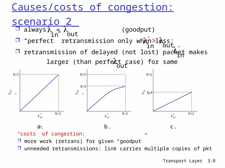
Causescosts of congestion scenario 2 always (goodput)
ldquoperfectrdquo retransmission only when loss
retransmission of delayed (not lost) packet makes
larger (than perfect case) for same
in
out
=
in
out
gt
in
out
ldquocostsrdquo of congestion more work (retrans) for given ldquogoodputrdquo unneeded retransmissions link carries multiple copies of pkt
R2
R2in
ou
t
b
R2
R2in
ou
t
a
R2
R2in
ou
t
c
R4
R3
Transport Layer 3-9
Causescosts of congestion scenario 3 four senders multihop paths timeoutretransmit
in
Q what happens as and increase
in
finite shared output link buffers
Host Ain original data
Host B
out
in original data plus retransmitted data
Transport Layer 3-10
Causescosts of congestion scenario 3
Another ldquocostrdquo of congestion when packet dropped any ldquoupstream transmission capacity
used for that packet was wasted
Host A
Host B
o
u
t
Transport Layer 3-11
Approaches towards congestion control
End-end congestion control
no explicit feedback from network
congestion inferred from end-system observed loss delay
approach taken by TCP
Network-assisted congestion control
routers provide feedback to end systems single bit indicating
congestion (SNA DECbit TCPIP ECN ATM)
explicit rate sender should send at
Two broad approaches towards congestion control
Transport Layer 3-12
Case study ATM ABR congestion control
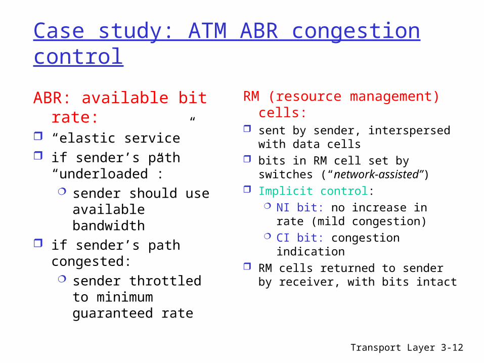
ABR available bit rate
ldquoelastic servicerdquo if senderrsquos path
ldquounderloadedrdquo sender should use
available bandwidth if senderrsquos path
congested sender throttled to
minimum guaranteed rate
RM (resource management) cells
sent by sender interspersed with data cells
bits in RM cell set by switches (ldquonetwork-assistedrdquo)
Implicit control NI bit no increase in rate
(mild congestion) CI bit congestion indication
RM cells returned to sender by receiver with bits intact
Transport Layer 3-13
Case study ATM ABR congestion control
two-byte ER (explicit rate) field in RM cell congested switch may lower ER value in cell senderrsquo send rate thus minimum supportable rate on
path
Scalability issue
Transport Layer 3-14
Outline
Principles of congestion control TCP congestion control
Transport Layer 3-15
TCP Congestion Control
end-end control (no network assistance)
sender limits transmission LastByteSent-LastByteAcked
CongWin Roughly
CongWin is dynamic function of perceived network congestion
How does sender perceive congestion
loss event = timeout or 3 duplicate acks
TCP sender reduces rate (CongWin) after loss event
three mechanisms AIMD slow start conservative after
timeout events
rate = CongWin
RTT Bytessec
Transport Layer 3-16
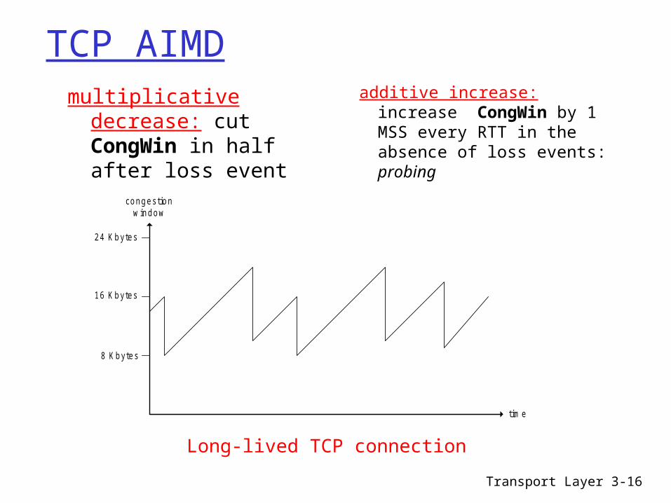
TCP AIMD
8 Kbytes
16 Kbytes
24 Kbytes
time
congestionwindow
multiplicative decrease cut CongWin in half after loss event
additive increase increase CongWin by 1 MSS every RTT in the absence of loss events probing
Long-lived TCP connection
Transport Layer 3-17
TCP Slow Start
When connection begins CongWin = 1 MSS Example MSS = 500
bytes amp RTT = 200 msec
initial rate = 20 kbps
available bandwidth may be gtgt MSSRTT desirable to quickly
ramp up to respectable rate
When connection begins increase rate exponentially fast until first loss event
Transport Layer 3-18
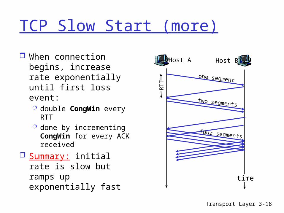
TCP Slow Start (more)
When connection begins increase rate exponentially until first loss event double CongWin every
RTT done by incrementing CongWin for every ACK received
Summary initial rate is slow but ramps up exponentially fast
Host A
one segment
RTT
Host B
time
two segments
four segments
Transport Layer 3-19
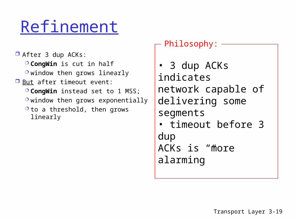
Refinement After 3 dup ACKs
CongWin is cut in half window then grows linearly
But after timeout event CongWin instead set to 1 MSS window then grows exponentially to a threshold then grows linearly
bull 3 dup ACKs indicates network capable of delivering some segmentsbull timeout before 3 dup ACKs is ldquomore alarmingrdquo
Philosophy
Transport Layer 3-20
Refinement (more)Q When should the
exponential increase switch to linear
A When CongWin gets to 12 of its value before timeout
Implementation Variable Threshold At loss event Threshold
is set to 12 of CongWin just before loss event
Transport Layer 3-21
Summary TCP Congestion Control
When CongWin is below Threshold sender in slow-start phase window grows exponentially
When CongWin is above Threshold sender is in congestion-avoidance phase window grows linearly
When a triple duplicate ACK occurs Threshold set to CongWin2 and CongWin set to Threshold
When timeout occurs Threshold set to CongWin2 and CongWin is set to 1 MSS
Transport Layer 3-22
TCP sender congestion control
Event State TCP Sender Action Commentary
ACK receipt for previously unacked data
Slow Start (SS)
CongWin = CongWin + MSS If (CongWin gt Threshold) set state to ldquoCongestion Avoidancerdquo
Resulting in a doubling of CongWin every RTT
ACK receipt for previously unacked data
CongestionAvoidance (CA)
CongWin = CongWin+MSS (MSSCongWin)
Additive increase resulting in increase of CongWin by 1 MSS every RTT
Loss event detected by triple duplicate ACK
SS or CA Threshold = CongWin2 CongWin = ThresholdSet state to ldquoCongestion Avoidancerdquo
Fast recovery implementing multiplicative decrease CongWin will not drop below 1 MSS
Timeout SS or CA Threshold = CongWin2 CongWin = 1 MSSSet state to ldquoSlow Startrdquo
Enter slow start
Duplicate ACK
SS or CA Increment duplicate ACK count for segment being acked
CongWin and Threshold not changed
Transport Layer 3-23
TCP throughput
Whatrsquos the average throughout ot TCP as a function of window size and RTT Ignore slow start
Let W be the window size when loss occurs
When window is W throughput is WRTT Just after loss window drops to W2
throughput to W2RTT Average throughout 75 WRTT
Transport Layer 3-24
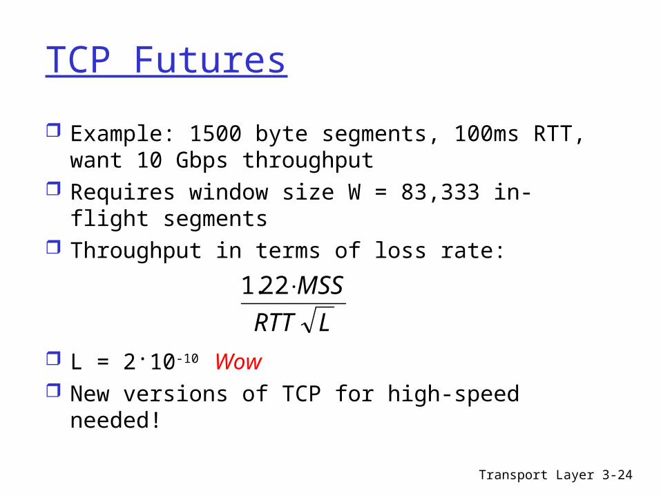
TCP Futures
Example 1500 byte segments 100ms RTT want 10 Gbps throughput
Requires window size W = 83333 in-flight segments
Throughput in terms of loss rate
L = 210-10 Wow New versions of TCP for high-speed needed
LRTT
MSS221
Transport Layer 3-25
Fairness goal if K TCP sessions share same bottleneck link of bandwidth R each should have average rate of RK
TCP connection 1
bottleneckrouter
capacity R
TCP connection 2
TCP Fairness
Transport Layer 3-26
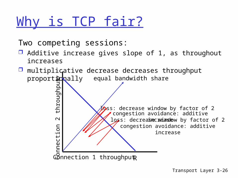
Why is TCP fair
Two competing sessions Additive increase gives slope of 1 as throughout increases multiplicative decrease decreases throughput proportionally
R
R
equal bandwidth share
Connection 1 throughputConnect
ion 2
th
roughput
congestion avoidance additive increaseloss decrease window by factor of 2
congestion avoidance additive increaseloss decrease window by factor of 2
Transport Layer 3-27
Fairness (more)
Fairness and UDP Multimedia apps
often do not use TCP do not want rate
throttled by congestion control
Instead use UDP pump audiovideo at
constant rate tolerate packet loss
Research area TCP friendly
Fairness and parallel TCP connections
nothing prevents app from opening parallel cnctions between 2 hosts
Web browsers do this Example link of rate R
supporting 9 cnctions new app asks for 1 TCP
gets rate R10 new app asks for 11 TCPs
gets R2
Transport Layer 3-28
Shrew
Very small but aggressive mammal that ferociously attacks and kills much larger animals with a venomous bite
Transport Layer 3-29
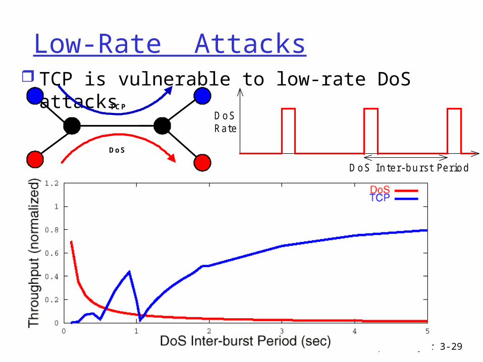
Low-Rate Attacks TCP is vulnerable to low-rate DoS attacks
DoSRate
DoS I nter- burst Period
TC P
DoS
Transport Layer 3-30
TCP a Dual Time-Scale Perspective
Two time-scales fundamentally required RTT time-scales (~10-100 ms)
bull AIMD control RTO time-scales (RTO=SRTT+4RTTVAR)
bull Avoid congestion collapse
Lower-bounding the RTO parameter [AllPax99] minRTO = 1 sec
bull to avoid spurious retransmissions RFC2988 recommends minRTO = 1 sec
Discrepancy between RTO and RTT tim e- scales isa key source of vulnerability to low rate attacks
Transport Layer 3-31
The Low-Rate AttackVictim
Attacker
TC
P S
en
din
g R
ate
Time
Do
S R
ate
Tim e
Transport Layer 3-32
The Low-Rate Attack
A short burst (~RTT) sufficient to create outage
Outage ndash event of correlated packet losses that forces TCP to enter RTO mechanism
Victim
Attacker
Do
S R
ate
Tim e
short burst (~RTT)
random initial phase
TC
P S
en
din
g R
ate
Tim e
outage
Transport Layer 3-33
The Low-Rate Attack
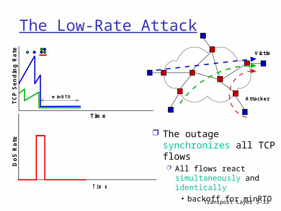
The outage synchronizes all TCP flows All flows react
simultaneously and identically
bull backoff for minRTO
Victim
Attacker
TC
P S
en
din
g R
ate
Tim e
minRTO
Do
S R
ate
Tim erandom initial phase
Transport Layer 3-34
The Low-Rate Attack
Once the TCP flows try to recover ndash hit them again
Exploit protocol determinism
Victim
AttackerTC
P S
en
din
g R
ate
Time
minRTO
Do
S R
ate
Tim erandom initial phase
Transport Layer 3-35
The Low-Rate Attack
And keep repeatinghellip
RTT-time-scale outages inter-spaced on minRTO periods can deny service to TCP traffic
Victim
Attacker
TC
P S
en
din
g R
ate
Tim e
minRTO minRTO
Do
S R
ate
Tim erandom initial phase
Transport Layer 3-36
Low-Rate Attacks TCP is vulnerable to low-rate DoS attacks
DoSRate
DoS I nter- burst Period
TC P
DoS
Transport Layer 3-37
Delay modeling - homework
Q How long does it take to receive an object from a Web server after sending a request
Ignoring congestion delay is influenced by
TCP connection establishment
data transmission delay slow start
Notation assumptions Assume one link between
client and server of rate R S MSS (bits) O object size (bits) no retransmissions (no loss no
corruption)
Window size First assume fixed congestion
window W segments Then dynamic window
modeling slow start
Transport Layer 3-38
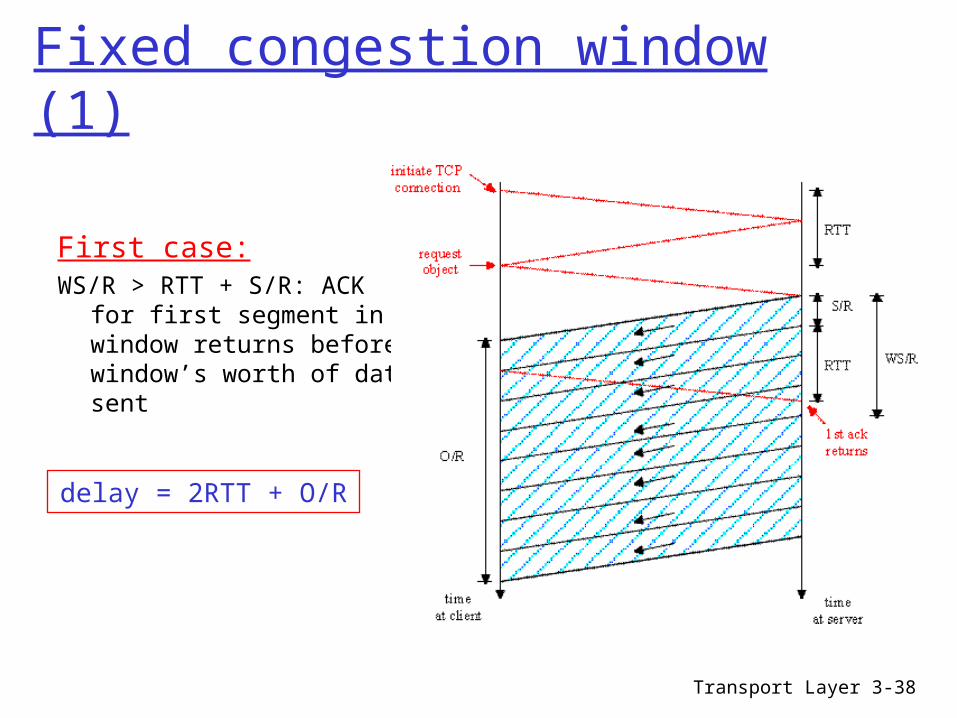
Fixed congestion window (1)
First caseWSR gt RTT + SR ACK for
first segment in window returns before windowrsquos worth of data sent
delay = 2RTT + OR
Transport Layer 3-39
Fixed congestion window (2)
Second case WSR lt RTT + SR
wait for ACK after sending windowrsquos worth of data sent
delay = 2RTT + OR+ (K-1)[SR + RTT - WSR]
Where K=OWS
Transport Layer 3-40
TCP Delay Modeling Slow Start (1)
Now suppose window grows according to slow start
Will show that the delay for one object is
R
S
R
SRTTP
R
ORTTLatency P )12(2
where P is the number of times TCP idles at server
1min KQP
- where Q is the number of times the server idles if the object were of infinite size
- and K is the number of windows that cover the object
Transport Layer 3-41
TCP Delay Modeling Slow Start (2)
RTT
initia te TCPconnection
requestobject
first w indow= S R
second w indow= 2S R
third w indow= 4S R
fourth w indow= 8S R
com pletetransm issionobject
delivered
tim e atc lient
tim e atserver
Examplebull OS = 15 segmentsbull K = 4 windowsbull Q = 2bull P = minK-1Q = 2
Server idles P=2 times
Delay componentsbull 2 RTT for connection estab and requestbull OR to transmit objectbull time server idles due to slow start
Server idles P = minK-1Q times
Transport Layer 3-42
TCP Delay Modeling (3)
R
S
R
SRTTPRTT
R
O
R
SRTT
R
SRTT
R
O
idleTimeRTTR
O
P
kP
k
P
pp
)12(][2
]2[2
2delay
1
1
1
th window after the timeidle 2 1 kR
SRTT
R
S k
ementacknowledg receivesserver until
segment send tostartsserver whenfrom time RTTR
S
window kth the transmit totime2 1
R
Sk
RTT
initia te TCPconnection
requestobject
first w indow= S R
second w indow= 2S R
third w indow= 4S R
fourth w indow= 8S R
com pletetransm issionobject
delivered
tim e atc lient
tim e atserver
Transport Layer 3-43
TCP Delay Modeling (4)
)1(log
)1(logmin
12min
222min
222min
2
2
110
110
S
OS
Okk
S
Ok
SOk
OSSSkK
k
k
k
Calculation of Q number of idles for infinite-size objectis similar (see HW)
Recall K = number of windows that cover object
How do we calculate K
Transport Layer 3-44
Summary principles behind transport
layer services multiplexing
demultiplexing reliable data transfer flow control congestion control
instantiation and implementation in the Internet UDP TCP
Next leaving the network
ldquoedgerdquo (application transport layers)
into the network ldquocorerdquo
Announcement Review of Previous Lecture TCP Connection Management Outline Principles of Congestion Control Causescosts of congestion scenario 1 Causescosts of congestion scenario 2 Slide 8 Causescosts of congestion scenario 3 Slide 10 Approaches towards congestion control Case study ATM ABR congestion control Slide 13 Slide 14 TCP Congestion Control TCP AIMD TCP Slow Start TCP Slow Start (more) Refinement Refinement (more) Summary TCP Congestion Control TCP sender congestion control TCP throughput TCP Futures TCP Fairness Why is TCP fair Fairness (more) Shrew Low-Rate Attacks TCP a Dual Time-Scale Perspective The Low-Rate Attack Slide 32 Slide 33 Slide 34 Slide 35 Slide 36 Delay modeling - homework Fixed congestion window (1) Fixed congestion window (2) TCP Delay Modeling Slow Start (1) TCP Delay Modeling Slow Start (2) TCP Delay Modeling (3) TCP Delay Modeling (4) Summary Page 2
Transport Layer 3-2
Review of Previous Lecture
Connection-oriented transport TCP Overview and segment structure
bull RTT and RTO Reliable data transfer
bull Timeout and fast retransmit Flow control
bull Donrsquot overwhelm the receiver Connection management
Transport Layer 3-3
TCP Connection Management
Closing a connectionThree way handshake
Step 1 client host sends TCP SYN segment to server specifies initial seq no data
Step 2 server host receives SYN replies with SYNACK segment server allocates buffers specifies server initial
seq Step 3 client receives SYNACK
replies with ACK segment which may contain data
client
FIN
server
ACK
ACK
FIN
close
close
closed
tim
ed w
ait
Transport Layer 3-4
Outline
Principles of congestion control TCP congestion control
Transport Layer 3-5
Principles of Congestion Control
Congestion informally ldquotoo many sources sending too
much data too fast for network to handlerdquo different from flow control manifestations
lost packets (buffer overflow at routers) long delays (queueing in router buffers)
a top-10 problem
Transport Layer 3-6
Causescosts of congestion scenario 1
two senders two receivers
one router infinite buffers
no retransmission
large delays when congested
maximum achievable throughput
unlimited shared output link buffers
Host Ain original data
Host B
out
Transport Layer 3-7
Causescosts of congestion scenario 2
one router finite buffers sender retransmission of lost packet
finite shared output link buffers
Host A in original data
Host B
out
in original data plus retransmitted data
Transport Layer 3-8
Causescosts of congestion scenario 2 always (goodput)
ldquoperfectrdquo retransmission only when loss
retransmission of delayed (not lost) packet makes
larger (than perfect case) for same
in
out
=
in
out
gt
in
out
ldquocostsrdquo of congestion more work (retrans) for given ldquogoodputrdquo unneeded retransmissions link carries multiple copies of pkt
R2
R2in
ou
t
b
R2
R2in
ou
t
a
R2
R2in
ou
t
c
R4
R3
Transport Layer 3-9
Causescosts of congestion scenario 3 four senders multihop paths timeoutretransmit
in
Q what happens as and increase
in
finite shared output link buffers
Host Ain original data
Host B
out
in original data plus retransmitted data
Transport Layer 3-10
Causescosts of congestion scenario 3
Another ldquocostrdquo of congestion when packet dropped any ldquoupstream transmission capacity
used for that packet was wasted
Host A
Host B
o
u
t
Transport Layer 3-11
Approaches towards congestion control
End-end congestion control
no explicit feedback from network
congestion inferred from end-system observed loss delay
approach taken by TCP
Network-assisted congestion control
routers provide feedback to end systems single bit indicating
congestion (SNA DECbit TCPIP ECN ATM)
explicit rate sender should send at
Two broad approaches towards congestion control
Transport Layer 3-12
Case study ATM ABR congestion control
ABR available bit rate
ldquoelastic servicerdquo if senderrsquos path
ldquounderloadedrdquo sender should use
available bandwidth if senderrsquos path
congested sender throttled to
minimum guaranteed rate
RM (resource management) cells
sent by sender interspersed with data cells
bits in RM cell set by switches (ldquonetwork-assistedrdquo)
Implicit control NI bit no increase in rate
(mild congestion) CI bit congestion indication
RM cells returned to sender by receiver with bits intact
Transport Layer 3-13
Case study ATM ABR congestion control
two-byte ER (explicit rate) field in RM cell congested switch may lower ER value in cell senderrsquo send rate thus minimum supportable rate on
path
Scalability issue
Transport Layer 3-14
Outline
Principles of congestion control TCP congestion control
Transport Layer 3-15
TCP Congestion Control
end-end control (no network assistance)
sender limits transmission LastByteSent-LastByteAcked
CongWin Roughly
CongWin is dynamic function of perceived network congestion
How does sender perceive congestion
loss event = timeout or 3 duplicate acks
TCP sender reduces rate (CongWin) after loss event
three mechanisms AIMD slow start conservative after
timeout events
rate = CongWin
RTT Bytessec
Transport Layer 3-16
TCP AIMD
8 Kbytes
16 Kbytes
24 Kbytes
time
congestionwindow
multiplicative decrease cut CongWin in half after loss event
additive increase increase CongWin by 1 MSS every RTT in the absence of loss events probing
Long-lived TCP connection
Transport Layer 3-17
TCP Slow Start
When connection begins CongWin = 1 MSS Example MSS = 500
bytes amp RTT = 200 msec
initial rate = 20 kbps
available bandwidth may be gtgt MSSRTT desirable to quickly
ramp up to respectable rate
When connection begins increase rate exponentially fast until first loss event
Transport Layer 3-18
TCP Slow Start (more)
When connection begins increase rate exponentially until first loss event double CongWin every
RTT done by incrementing CongWin for every ACK received
Summary initial rate is slow but ramps up exponentially fast
Host A
one segment
RTT
Host B
time
two segments
four segments
Transport Layer 3-19
Refinement After 3 dup ACKs
CongWin is cut in half window then grows linearly
But after timeout event CongWin instead set to 1 MSS window then grows exponentially to a threshold then grows linearly
bull 3 dup ACKs indicates network capable of delivering some segmentsbull timeout before 3 dup ACKs is ldquomore alarmingrdquo
Philosophy
Transport Layer 3-20
Refinement (more)Q When should the
exponential increase switch to linear
A When CongWin gets to 12 of its value before timeout
Implementation Variable Threshold At loss event Threshold
is set to 12 of CongWin just before loss event
Transport Layer 3-21
Summary TCP Congestion Control
When CongWin is below Threshold sender in slow-start phase window grows exponentially
When CongWin is above Threshold sender is in congestion-avoidance phase window grows linearly
When a triple duplicate ACK occurs Threshold set to CongWin2 and CongWin set to Threshold
When timeout occurs Threshold set to CongWin2 and CongWin is set to 1 MSS
Transport Layer 3-22
TCP sender congestion control
Event State TCP Sender Action Commentary
ACK receipt for previously unacked data
Slow Start (SS)
CongWin = CongWin + MSS If (CongWin gt Threshold) set state to ldquoCongestion Avoidancerdquo
Resulting in a doubling of CongWin every RTT
ACK receipt for previously unacked data
CongestionAvoidance (CA)
CongWin = CongWin+MSS (MSSCongWin)
Additive increase resulting in increase of CongWin by 1 MSS every RTT
Loss event detected by triple duplicate ACK
SS or CA Threshold = CongWin2 CongWin = ThresholdSet state to ldquoCongestion Avoidancerdquo
Fast recovery implementing multiplicative decrease CongWin will not drop below 1 MSS
Timeout SS or CA Threshold = CongWin2 CongWin = 1 MSSSet state to ldquoSlow Startrdquo
Enter slow start
Duplicate ACK
SS or CA Increment duplicate ACK count for segment being acked
CongWin and Threshold not changed
Transport Layer 3-23
TCP throughput
Whatrsquos the average throughout ot TCP as a function of window size and RTT Ignore slow start
Let W be the window size when loss occurs
When window is W throughput is WRTT Just after loss window drops to W2
throughput to W2RTT Average throughout 75 WRTT
Transport Layer 3-24
TCP Futures
Example 1500 byte segments 100ms RTT want 10 Gbps throughput
Requires window size W = 83333 in-flight segments
Throughput in terms of loss rate
L = 210-10 Wow New versions of TCP for high-speed needed
LRTT
MSS221
Transport Layer 3-25
Fairness goal if K TCP sessions share same bottleneck link of bandwidth R each should have average rate of RK
TCP connection 1
bottleneckrouter
capacity R
TCP connection 2
TCP Fairness
Transport Layer 3-26
Why is TCP fair
Two competing sessions Additive increase gives slope of 1 as throughout increases multiplicative decrease decreases throughput proportionally
R
R
equal bandwidth share
Connection 1 throughputConnect
ion 2
th
roughput
congestion avoidance additive increaseloss decrease window by factor of 2
congestion avoidance additive increaseloss decrease window by factor of 2
Transport Layer 3-27
Fairness (more)
Fairness and UDP Multimedia apps
often do not use TCP do not want rate
throttled by congestion control
Instead use UDP pump audiovideo at
constant rate tolerate packet loss
Research area TCP friendly
Fairness and parallel TCP connections
nothing prevents app from opening parallel cnctions between 2 hosts
Web browsers do this Example link of rate R
supporting 9 cnctions new app asks for 1 TCP
gets rate R10 new app asks for 11 TCPs
gets R2
Transport Layer 3-28
Shrew
Very small but aggressive mammal that ferociously attacks and kills much larger animals with a venomous bite
Transport Layer 3-29
Low-Rate Attacks TCP is vulnerable to low-rate DoS attacks
DoSRate
DoS I nter- burst Period
TC P
DoS
Transport Layer 3-30
TCP a Dual Time-Scale Perspective
Two time-scales fundamentally required RTT time-scales (~10-100 ms)
bull AIMD control RTO time-scales (RTO=SRTT+4RTTVAR)
bull Avoid congestion collapse
Lower-bounding the RTO parameter [AllPax99] minRTO = 1 sec
bull to avoid spurious retransmissions RFC2988 recommends minRTO = 1 sec
Discrepancy between RTO and RTT tim e- scales isa key source of vulnerability to low rate attacks
Transport Layer 3-31
The Low-Rate AttackVictim
Attacker
TC
P S
en
din
g R
ate
Time
Do
S R
ate
Tim e
Transport Layer 3-32
The Low-Rate Attack
A short burst (~RTT) sufficient to create outage
Outage ndash event of correlated packet losses that forces TCP to enter RTO mechanism
Victim
Attacker
Do
S R
ate
Tim e
short burst (~RTT)
random initial phase
TC
P S
en
din
g R
ate
Tim e
outage
Transport Layer 3-33
The Low-Rate Attack
The outage synchronizes all TCP flows All flows react
simultaneously and identically
bull backoff for minRTO
Victim
Attacker
TC
P S
en
din
g R
ate
Tim e
minRTO
Do
S R
ate
Tim erandom initial phase
Transport Layer 3-34
The Low-Rate Attack
Once the TCP flows try to recover ndash hit them again
Exploit protocol determinism
Victim
AttackerTC
P S
en
din
g R
ate
Time
minRTO
Do
S R
ate
Tim erandom initial phase
Transport Layer 3-35
The Low-Rate Attack
And keep repeatinghellip
RTT-time-scale outages inter-spaced on minRTO periods can deny service to TCP traffic
Victim
Attacker
TC
P S
en
din
g R
ate
Tim e
minRTO minRTO
Do
S R
ate
Tim erandom initial phase
Transport Layer 3-36
Low-Rate Attacks TCP is vulnerable to low-rate DoS attacks
DoSRate
DoS I nter- burst Period
TC P
DoS
Transport Layer 3-37
Delay modeling - homework
Q How long does it take to receive an object from a Web server after sending a request
Ignoring congestion delay is influenced by
TCP connection establishment
data transmission delay slow start
Notation assumptions Assume one link between
client and server of rate R S MSS (bits) O object size (bits) no retransmissions (no loss no
corruption)
Window size First assume fixed congestion
window W segments Then dynamic window
modeling slow start
Transport Layer 3-38
Fixed congestion window (1)
First caseWSR gt RTT + SR ACK for
first segment in window returns before windowrsquos worth of data sent
delay = 2RTT + OR
Transport Layer 3-39
Fixed congestion window (2)
Second case WSR lt RTT + SR
wait for ACK after sending windowrsquos worth of data sent
delay = 2RTT + OR+ (K-1)[SR + RTT - WSR]
Where K=OWS
Transport Layer 3-40
TCP Delay Modeling Slow Start (1)
Now suppose window grows according to slow start
Will show that the delay for one object is
R
S
R
SRTTP
R
ORTTLatency P )12(2
where P is the number of times TCP idles at server
1min KQP
- where Q is the number of times the server idles if the object were of infinite size
- and K is the number of windows that cover the object
Transport Layer 3-41
TCP Delay Modeling Slow Start (2)
RTT
initia te TCPconnection
requestobject
first w indow= S R
second w indow= 2S R
third w indow= 4S R
fourth w indow= 8S R
com pletetransm issionobject
delivered
tim e atc lient
tim e atserver
Examplebull OS = 15 segmentsbull K = 4 windowsbull Q = 2bull P = minK-1Q = 2
Server idles P=2 times
Delay componentsbull 2 RTT for connection estab and requestbull OR to transmit objectbull time server idles due to slow start
Server idles P = minK-1Q times
Transport Layer 3-42
TCP Delay Modeling (3)
R
S
R
SRTTPRTT
R
O
R
SRTT
R
SRTT
R
O
idleTimeRTTR
O
P
kP
k
P
pp
)12(][2
]2[2
2delay
1
1
1
th window after the timeidle 2 1 kR
SRTT
R
S k
ementacknowledg receivesserver until
segment send tostartsserver whenfrom time RTTR
S
window kth the transmit totime2 1
R
Sk
RTT
initia te TCPconnection
requestobject
first w indow= S R
second w indow= 2S R
third w indow= 4S R
fourth w indow= 8S R
com pletetransm issionobject
delivered
tim e atc lient
tim e atserver
Transport Layer 3-43
TCP Delay Modeling (4)
)1(log
)1(logmin
12min
222min
222min
2
2
110
110
S
OS
Okk
S
Ok
SOk
OSSSkK
k
k
k
Calculation of Q number of idles for infinite-size objectis similar (see HW)
Recall K = number of windows that cover object
How do we calculate K
Transport Layer 3-44
Summary principles behind transport
layer services multiplexing
demultiplexing reliable data transfer flow control congestion control
instantiation and implementation in the Internet UDP TCP
Next leaving the network
ldquoedgerdquo (application transport layers)
into the network ldquocorerdquo
Announcement Review of Previous Lecture TCP Connection Management Outline Principles of Congestion Control Causescosts of congestion scenario 1 Causescosts of congestion scenario 2 Slide 8 Causescosts of congestion scenario 3 Slide 10 Approaches towards congestion control Case study ATM ABR congestion control Slide 13 Slide 14 TCP Congestion Control TCP AIMD TCP Slow Start TCP Slow Start (more) Refinement Refinement (more) Summary TCP Congestion Control TCP sender congestion control TCP throughput TCP Futures TCP Fairness Why is TCP fair Fairness (more) Shrew Low-Rate Attacks TCP a Dual Time-Scale Perspective The Low-Rate Attack Slide 32 Slide 33 Slide 34 Slide 35 Slide 36 Delay modeling - homework Fixed congestion window (1) Fixed congestion window (2) TCP Delay Modeling Slow Start (1) TCP Delay Modeling Slow Start (2) TCP Delay Modeling (3) TCP Delay Modeling (4) Summary Page 3
Transport Layer 3-3
TCP Connection Management
Closing a connectionThree way handshake
Step 1 client host sends TCP SYN segment to server specifies initial seq no data
Step 2 server host receives SYN replies with SYNACK segment server allocates buffers specifies server initial
seq Step 3 client receives SYNACK
replies with ACK segment which may contain data
client
FIN
server
ACK
ACK
FIN
close
close
closed
tim
ed w
ait
Transport Layer 3-4
Outline
Principles of congestion control TCP congestion control
Transport Layer 3-5
Principles of Congestion Control
Congestion informally ldquotoo many sources sending too
much data too fast for network to handlerdquo different from flow control manifestations
lost packets (buffer overflow at routers) long delays (queueing in router buffers)
a top-10 problem
Transport Layer 3-6
Causescosts of congestion scenario 1
two senders two receivers
one router infinite buffers
no retransmission
large delays when congested
maximum achievable throughput
unlimited shared output link buffers
Host Ain original data
Host B
out
Transport Layer 3-7
Causescosts of congestion scenario 2
one router finite buffers sender retransmission of lost packet
finite shared output link buffers
Host A in original data
Host B
out
in original data plus retransmitted data
Transport Layer 3-8
Causescosts of congestion scenario 2 always (goodput)
ldquoperfectrdquo retransmission only when loss
retransmission of delayed (not lost) packet makes
larger (than perfect case) for same
in
out
=
in
out
gt
in
out
ldquocostsrdquo of congestion more work (retrans) for given ldquogoodputrdquo unneeded retransmissions link carries multiple copies of pkt
R2
R2in
ou
t
b
R2
R2in
ou
t
a
R2
R2in
ou
t
c
R4
R3
Transport Layer 3-9
Causescosts of congestion scenario 3 four senders multihop paths timeoutretransmit
in
Q what happens as and increase
in
finite shared output link buffers
Host Ain original data
Host B
out
in original data plus retransmitted data
Transport Layer 3-10
Causescosts of congestion scenario 3
Another ldquocostrdquo of congestion when packet dropped any ldquoupstream transmission capacity
used for that packet was wasted
Host A
Host B
o
u
t
Transport Layer 3-11
Approaches towards congestion control
End-end congestion control
no explicit feedback from network
congestion inferred from end-system observed loss delay
approach taken by TCP
Network-assisted congestion control
routers provide feedback to end systems single bit indicating
congestion (SNA DECbit TCPIP ECN ATM)
explicit rate sender should send at
Two broad approaches towards congestion control
Transport Layer 3-12
Case study ATM ABR congestion control
ABR available bit rate
ldquoelastic servicerdquo if senderrsquos path
ldquounderloadedrdquo sender should use
available bandwidth if senderrsquos path
congested sender throttled to
minimum guaranteed rate
RM (resource management) cells
sent by sender interspersed with data cells
bits in RM cell set by switches (ldquonetwork-assistedrdquo)
Implicit control NI bit no increase in rate
(mild congestion) CI bit congestion indication
RM cells returned to sender by receiver with bits intact
Transport Layer 3-13
Case study ATM ABR congestion control
two-byte ER (explicit rate) field in RM cell congested switch may lower ER value in cell senderrsquo send rate thus minimum supportable rate on
path
Scalability issue
Transport Layer 3-14
Outline
Principles of congestion control TCP congestion control
Transport Layer 3-15
TCP Congestion Control
end-end control (no network assistance)
sender limits transmission LastByteSent-LastByteAcked
CongWin Roughly
CongWin is dynamic function of perceived network congestion
How does sender perceive congestion
loss event = timeout or 3 duplicate acks
TCP sender reduces rate (CongWin) after loss event
three mechanisms AIMD slow start conservative after
timeout events
rate = CongWin
RTT Bytessec
Transport Layer 3-16
TCP AIMD
8 Kbytes
16 Kbytes
24 Kbytes
time
congestionwindow
multiplicative decrease cut CongWin in half after loss event
additive increase increase CongWin by 1 MSS every RTT in the absence of loss events probing
Long-lived TCP connection
Transport Layer 3-17
TCP Slow Start
When connection begins CongWin = 1 MSS Example MSS = 500
bytes amp RTT = 200 msec
initial rate = 20 kbps
available bandwidth may be gtgt MSSRTT desirable to quickly
ramp up to respectable rate
When connection begins increase rate exponentially fast until first loss event
Transport Layer 3-18
TCP Slow Start (more)
When connection begins increase rate exponentially until first loss event double CongWin every
RTT done by incrementing CongWin for every ACK received
Summary initial rate is slow but ramps up exponentially fast
Host A
one segment
RTT
Host B
time
two segments
four segments
Transport Layer 3-19
Refinement After 3 dup ACKs
CongWin is cut in half window then grows linearly
But after timeout event CongWin instead set to 1 MSS window then grows exponentially to a threshold then grows linearly
bull 3 dup ACKs indicates network capable of delivering some segmentsbull timeout before 3 dup ACKs is ldquomore alarmingrdquo
Philosophy
Transport Layer 3-20
Refinement (more)Q When should the
exponential increase switch to linear
A When CongWin gets to 12 of its value before timeout
Implementation Variable Threshold At loss event Threshold
is set to 12 of CongWin just before loss event
Transport Layer 3-21
Summary TCP Congestion Control
When CongWin is below Threshold sender in slow-start phase window grows exponentially
When CongWin is above Threshold sender is in congestion-avoidance phase window grows linearly
When a triple duplicate ACK occurs Threshold set to CongWin2 and CongWin set to Threshold
When timeout occurs Threshold set to CongWin2 and CongWin is set to 1 MSS
Transport Layer 3-22
TCP sender congestion control
Event State TCP Sender Action Commentary
ACK receipt for previously unacked data
Slow Start (SS)
CongWin = CongWin + MSS If (CongWin gt Threshold) set state to ldquoCongestion Avoidancerdquo
Resulting in a doubling of CongWin every RTT
ACK receipt for previously unacked data
CongestionAvoidance (CA)
CongWin = CongWin+MSS (MSSCongWin)
Additive increase resulting in increase of CongWin by 1 MSS every RTT
Loss event detected by triple duplicate ACK
SS or CA Threshold = CongWin2 CongWin = ThresholdSet state to ldquoCongestion Avoidancerdquo
Fast recovery implementing multiplicative decrease CongWin will not drop below 1 MSS
Timeout SS or CA Threshold = CongWin2 CongWin = 1 MSSSet state to ldquoSlow Startrdquo
Enter slow start
Duplicate ACK
SS or CA Increment duplicate ACK count for segment being acked
CongWin and Threshold not changed
Transport Layer 3-23
TCP throughput
Whatrsquos the average throughout ot TCP as a function of window size and RTT Ignore slow start
Let W be the window size when loss occurs
When window is W throughput is WRTT Just after loss window drops to W2
throughput to W2RTT Average throughout 75 WRTT
Transport Layer 3-24
TCP Futures
Example 1500 byte segments 100ms RTT want 10 Gbps throughput
Requires window size W = 83333 in-flight segments
Throughput in terms of loss rate
L = 210-10 Wow New versions of TCP for high-speed needed
LRTT
MSS221
Transport Layer 3-25
Fairness goal if K TCP sessions share same bottleneck link of bandwidth R each should have average rate of RK
TCP connection 1
bottleneckrouter
capacity R
TCP connection 2
TCP Fairness
Transport Layer 3-26
Why is TCP fair
Two competing sessions Additive increase gives slope of 1 as throughout increases multiplicative decrease decreases throughput proportionally
R
R
equal bandwidth share
Connection 1 throughputConnect
ion 2
th
roughput
congestion avoidance additive increaseloss decrease window by factor of 2
congestion avoidance additive increaseloss decrease window by factor of 2
Transport Layer 3-27
Fairness (more)
Fairness and UDP Multimedia apps
often do not use TCP do not want rate
throttled by congestion control
Instead use UDP pump audiovideo at
constant rate tolerate packet loss
Research area TCP friendly
Fairness and parallel TCP connections
nothing prevents app from opening parallel cnctions between 2 hosts
Web browsers do this Example link of rate R
supporting 9 cnctions new app asks for 1 TCP
gets rate R10 new app asks for 11 TCPs
gets R2
Transport Layer 3-28
Shrew
Very small but aggressive mammal that ferociously attacks and kills much larger animals with a venomous bite
Transport Layer 3-29
Low-Rate Attacks TCP is vulnerable to low-rate DoS attacks
DoSRate
DoS I nter- burst Period
TC P
DoS
Transport Layer 3-30
TCP a Dual Time-Scale Perspective
Two time-scales fundamentally required RTT time-scales (~10-100 ms)
bull AIMD control RTO time-scales (RTO=SRTT+4RTTVAR)
bull Avoid congestion collapse
Lower-bounding the RTO parameter [AllPax99] minRTO = 1 sec
bull to avoid spurious retransmissions RFC2988 recommends minRTO = 1 sec
Discrepancy between RTO and RTT tim e- scales isa key source of vulnerability to low rate attacks
Transport Layer 3-31
The Low-Rate AttackVictim
Attacker
TC
P S
en
din
g R
ate
Time
Do
S R
ate
Tim e
Transport Layer 3-32
The Low-Rate Attack
A short burst (~RTT) sufficient to create outage
Outage ndash event of correlated packet losses that forces TCP to enter RTO mechanism
Victim
Attacker
Do
S R
ate
Tim e
short burst (~RTT)
random initial phase
TC
P S
en
din
g R
ate
Tim e
outage
Transport Layer 3-33
The Low-Rate Attack
The outage synchronizes all TCP flows All flows react
simultaneously and identically
bull backoff for minRTO
Victim
Attacker
TC
P S
en
din
g R
ate
Tim e
minRTO
Do
S R
ate
Tim erandom initial phase
Transport Layer 3-34
The Low-Rate Attack
Once the TCP flows try to recover ndash hit them again
Exploit protocol determinism
Victim
AttackerTC
P S
en
din
g R
ate
Time
minRTO
Do
S R
ate
Tim erandom initial phase
Transport Layer 3-35
The Low-Rate Attack
And keep repeatinghellip
RTT-time-scale outages inter-spaced on minRTO periods can deny service to TCP traffic
Victim
Attacker
TC
P S
en
din
g R
ate
Tim e
minRTO minRTO
Do
S R
ate
Tim erandom initial phase
Transport Layer 3-36
Low-Rate Attacks TCP is vulnerable to low-rate DoS attacks
DoSRate
DoS I nter- burst Period
TC P
DoS
Transport Layer 3-37
Delay modeling - homework
Q How long does it take to receive an object from a Web server after sending a request
Ignoring congestion delay is influenced by
TCP connection establishment
data transmission delay slow start
Notation assumptions Assume one link between
client and server of rate R S MSS (bits) O object size (bits) no retransmissions (no loss no
corruption)
Window size First assume fixed congestion
window W segments Then dynamic window
modeling slow start
Transport Layer 3-38
Fixed congestion window (1)
First caseWSR gt RTT + SR ACK for
first segment in window returns before windowrsquos worth of data sent
delay = 2RTT + OR
Transport Layer 3-39
Fixed congestion window (2)
Second case WSR lt RTT + SR
wait for ACK after sending windowrsquos worth of data sent
delay = 2RTT + OR+ (K-1)[SR + RTT - WSR]
Where K=OWS
Transport Layer 3-40
TCP Delay Modeling Slow Start (1)
Now suppose window grows according to slow start
Will show that the delay for one object is
R
S
R
SRTTP
R
ORTTLatency P )12(2
where P is the number of times TCP idles at server
1min KQP
- where Q is the number of times the server idles if the object were of infinite size
- and K is the number of windows that cover the object
Transport Layer 3-41
TCP Delay Modeling Slow Start (2)
RTT
initia te TCPconnection
requestobject
first w indow= S R
second w indow= 2S R
third w indow= 4S R
fourth w indow= 8S R
com pletetransm issionobject
delivered
tim e atc lient
tim e atserver
Examplebull OS = 15 segmentsbull K = 4 windowsbull Q = 2bull P = minK-1Q = 2
Server idles P=2 times
Delay componentsbull 2 RTT for connection estab and requestbull OR to transmit objectbull time server idles due to slow start
Server idles P = minK-1Q times
Transport Layer 3-42
TCP Delay Modeling (3)
R
S
R
SRTTPRTT
R
O
R
SRTT
R
SRTT
R
O
idleTimeRTTR
O
P
kP
k
P
pp
)12(][2
]2[2
2delay
1
1
1
th window after the timeidle 2 1 kR
SRTT
R
S k
ementacknowledg receivesserver until
segment send tostartsserver whenfrom time RTTR
S
window kth the transmit totime2 1
R
Sk
RTT
initia te TCPconnection
requestobject
first w indow= S R
second w indow= 2S R
third w indow= 4S R
fourth w indow= 8S R
com pletetransm issionobject
delivered
tim e atc lient
tim e atserver
Transport Layer 3-43
TCP Delay Modeling (4)
)1(log
)1(logmin
12min
222min
222min
2
2
110
110
S
OS
Okk
S
Ok
SOk
OSSSkK
k
k
k
Calculation of Q number of idles for infinite-size objectis similar (see HW)
Recall K = number of windows that cover object
How do we calculate K
Transport Layer 3-44
Summary principles behind transport
layer services multiplexing
demultiplexing reliable data transfer flow control congestion control
instantiation and implementation in the Internet UDP TCP
Next leaving the network
ldquoedgerdquo (application transport layers)
into the network ldquocorerdquo
Announcement Review of Previous Lecture TCP Connection Management Outline Principles of Congestion Control Causescosts of congestion scenario 1 Causescosts of congestion scenario 2 Slide 8 Causescosts of congestion scenario 3 Slide 10 Approaches towards congestion control Case study ATM ABR congestion control Slide 13 Slide 14 TCP Congestion Control TCP AIMD TCP Slow Start TCP Slow Start (more) Refinement Refinement (more) Summary TCP Congestion Control TCP sender congestion control TCP throughput TCP Futures TCP Fairness Why is TCP fair Fairness (more) Shrew Low-Rate Attacks TCP a Dual Time-Scale Perspective The Low-Rate Attack Slide 32 Slide 33 Slide 34 Slide 35 Slide 36 Delay modeling - homework Fixed congestion window (1) Fixed congestion window (2) TCP Delay Modeling Slow Start (1) TCP Delay Modeling Slow Start (2) TCP Delay Modeling (3) TCP Delay Modeling (4) Summary Page 4
Transport Layer 3-4
Outline
Principles of congestion control TCP congestion control
Transport Layer 3-5
Principles of Congestion Control
Congestion informally ldquotoo many sources sending too
much data too fast for network to handlerdquo different from flow control manifestations
lost packets (buffer overflow at routers) long delays (queueing in router buffers)
a top-10 problem
Transport Layer 3-6
Causescosts of congestion scenario 1
two senders two receivers
one router infinite buffers
no retransmission
large delays when congested
maximum achievable throughput
unlimited shared output link buffers
Host Ain original data
Host B
out
Transport Layer 3-7
Causescosts of congestion scenario 2
one router finite buffers sender retransmission of lost packet
finite shared output link buffers
Host A in original data
Host B
out
in original data plus retransmitted data
Transport Layer 3-8
Causescosts of congestion scenario 2 always (goodput)
ldquoperfectrdquo retransmission only when loss
retransmission of delayed (not lost) packet makes
larger (than perfect case) for same
in
out
=
in
out
gt
in
out
ldquocostsrdquo of congestion more work (retrans) for given ldquogoodputrdquo unneeded retransmissions link carries multiple copies of pkt
R2
R2in
ou
t
b
R2
R2in
ou
t
a
R2
R2in
ou
t
c
R4
R3
Transport Layer 3-9
Causescosts of congestion scenario 3 four senders multihop paths timeoutretransmit
in
Q what happens as and increase
in
finite shared output link buffers
Host Ain original data
Host B
out
in original data plus retransmitted data
Transport Layer 3-10
Causescosts of congestion scenario 3
Another ldquocostrdquo of congestion when packet dropped any ldquoupstream transmission capacity
used for that packet was wasted
Host A
Host B
o
u
t
Transport Layer 3-11
Approaches towards congestion control
End-end congestion control
no explicit feedback from network
congestion inferred from end-system observed loss delay
approach taken by TCP
Network-assisted congestion control
routers provide feedback to end systems single bit indicating
congestion (SNA DECbit TCPIP ECN ATM)
explicit rate sender should send at
Two broad approaches towards congestion control
Transport Layer 3-12
Case study ATM ABR congestion control
ABR available bit rate
ldquoelastic servicerdquo if senderrsquos path
ldquounderloadedrdquo sender should use
available bandwidth if senderrsquos path
congested sender throttled to
minimum guaranteed rate
RM (resource management) cells
sent by sender interspersed with data cells
bits in RM cell set by switches (ldquonetwork-assistedrdquo)
Implicit control NI bit no increase in rate
(mild congestion) CI bit congestion indication
RM cells returned to sender by receiver with bits intact
Transport Layer 3-13
Case study ATM ABR congestion control
two-byte ER (explicit rate) field in RM cell congested switch may lower ER value in cell senderrsquo send rate thus minimum supportable rate on
path
Scalability issue
Transport Layer 3-14
Outline
Principles of congestion control TCP congestion control
Transport Layer 3-15
TCP Congestion Control
end-end control (no network assistance)
sender limits transmission LastByteSent-LastByteAcked
CongWin Roughly
CongWin is dynamic function of perceived network congestion
How does sender perceive congestion
loss event = timeout or 3 duplicate acks
TCP sender reduces rate (CongWin) after loss event
three mechanisms AIMD slow start conservative after
timeout events
rate = CongWin
RTT Bytessec
Transport Layer 3-16
TCP AIMD
8 Kbytes
16 Kbytes
24 Kbytes
time
congestionwindow
multiplicative decrease cut CongWin in half after loss event
additive increase increase CongWin by 1 MSS every RTT in the absence of loss events probing
Long-lived TCP connection
Transport Layer 3-17
TCP Slow Start
When connection begins CongWin = 1 MSS Example MSS = 500
bytes amp RTT = 200 msec
initial rate = 20 kbps
available bandwidth may be gtgt MSSRTT desirable to quickly
ramp up to respectable rate
When connection begins increase rate exponentially fast until first loss event
Transport Layer 3-18
TCP Slow Start (more)
When connection begins increase rate exponentially until first loss event double CongWin every
RTT done by incrementing CongWin for every ACK received
Summary initial rate is slow but ramps up exponentially fast
Host A
one segment
RTT
Host B
time
two segments
four segments
Transport Layer 3-19
Refinement After 3 dup ACKs
CongWin is cut in half window then grows linearly
But after timeout event CongWin instead set to 1 MSS window then grows exponentially to a threshold then grows linearly
bull 3 dup ACKs indicates network capable of delivering some segmentsbull timeout before 3 dup ACKs is ldquomore alarmingrdquo
Philosophy
Transport Layer 3-20
Refinement (more)Q When should the
exponential increase switch to linear
A When CongWin gets to 12 of its value before timeout
Implementation Variable Threshold At loss event Threshold
is set to 12 of CongWin just before loss event
Transport Layer 3-21
Summary TCP Congestion Control
When CongWin is below Threshold sender in slow-start phase window grows exponentially
When CongWin is above Threshold sender is in congestion-avoidance phase window grows linearly
When a triple duplicate ACK occurs Threshold set to CongWin2 and CongWin set to Threshold
When timeout occurs Threshold set to CongWin2 and CongWin is set to 1 MSS
Transport Layer 3-22
TCP sender congestion control
Event State TCP Sender Action Commentary
ACK receipt for previously unacked data
Slow Start (SS)
CongWin = CongWin + MSS If (CongWin gt Threshold) set state to ldquoCongestion Avoidancerdquo
Resulting in a doubling of CongWin every RTT
ACK receipt for previously unacked data
CongestionAvoidance (CA)
CongWin = CongWin+MSS (MSSCongWin)
Additive increase resulting in increase of CongWin by 1 MSS every RTT
Loss event detected by triple duplicate ACK
SS or CA Threshold = CongWin2 CongWin = ThresholdSet state to ldquoCongestion Avoidancerdquo
Fast recovery implementing multiplicative decrease CongWin will not drop below 1 MSS
Timeout SS or CA Threshold = CongWin2 CongWin = 1 MSSSet state to ldquoSlow Startrdquo
Enter slow start
Duplicate ACK
SS or CA Increment duplicate ACK count for segment being acked
CongWin and Threshold not changed
Transport Layer 3-23
TCP throughput
Whatrsquos the average throughout ot TCP as a function of window size and RTT Ignore slow start
Let W be the window size when loss occurs
When window is W throughput is WRTT Just after loss window drops to W2
throughput to W2RTT Average throughout 75 WRTT
Transport Layer 3-24
TCP Futures
Example 1500 byte segments 100ms RTT want 10 Gbps throughput
Requires window size W = 83333 in-flight segments
Throughput in terms of loss rate
L = 210-10 Wow New versions of TCP for high-speed needed
LRTT
MSS221
Transport Layer 3-25
Fairness goal if K TCP sessions share same bottleneck link of bandwidth R each should have average rate of RK
TCP connection 1
bottleneckrouter
capacity R
TCP connection 2
TCP Fairness
Transport Layer 3-26
Why is TCP fair
Two competing sessions Additive increase gives slope of 1 as throughout increases multiplicative decrease decreases throughput proportionally
R
R
equal bandwidth share
Connection 1 throughputConnect
ion 2
th
roughput
congestion avoidance additive increaseloss decrease window by factor of 2
congestion avoidance additive increaseloss decrease window by factor of 2
Transport Layer 3-27
Fairness (more)
Fairness and UDP Multimedia apps
often do not use TCP do not want rate
throttled by congestion control
Instead use UDP pump audiovideo at
constant rate tolerate packet loss
Research area TCP friendly
Fairness and parallel TCP connections
nothing prevents app from opening parallel cnctions between 2 hosts
Web browsers do this Example link of rate R
supporting 9 cnctions new app asks for 1 TCP
gets rate R10 new app asks for 11 TCPs
gets R2
Transport Layer 3-28
Shrew
Very small but aggressive mammal that ferociously attacks and kills much larger animals with a venomous bite
Transport Layer 3-29
Low-Rate Attacks TCP is vulnerable to low-rate DoS attacks
DoSRate
DoS I nter- burst Period
TC P
DoS
Transport Layer 3-30
TCP a Dual Time-Scale Perspective
Two time-scales fundamentally required RTT time-scales (~10-100 ms)
bull AIMD control RTO time-scales (RTO=SRTT+4RTTVAR)
bull Avoid congestion collapse
Lower-bounding the RTO parameter [AllPax99] minRTO = 1 sec
bull to avoid spurious retransmissions RFC2988 recommends minRTO = 1 sec
Discrepancy between RTO and RTT tim e- scales isa key source of vulnerability to low rate attacks
Transport Layer 3-31
The Low-Rate AttackVictim
Attacker
TC
P S
en
din
g R
ate
Time
Do
S R
ate
Tim e
Transport Layer 3-32
The Low-Rate Attack
A short burst (~RTT) sufficient to create outage
Outage ndash event of correlated packet losses that forces TCP to enter RTO mechanism
Victim
Attacker
Do
S R
ate
Tim e
short burst (~RTT)
random initial phase
TC
P S
en
din
g R
ate
Tim e
outage
Transport Layer 3-33
The Low-Rate Attack
The outage synchronizes all TCP flows All flows react
simultaneously and identically
bull backoff for minRTO
Victim
Attacker
TC
P S
en
din
g R
ate
Tim e
minRTO
Do
S R
ate
Tim erandom initial phase
Transport Layer 3-34
The Low-Rate Attack
Once the TCP flows try to recover ndash hit them again
Exploit protocol determinism
Victim
AttackerTC
P S
en
din
g R
ate
Time
minRTO
Do
S R
ate
Tim erandom initial phase
Transport Layer 3-35
The Low-Rate Attack
And keep repeatinghellip
RTT-time-scale outages inter-spaced on minRTO periods can deny service to TCP traffic
Victim
Attacker
TC
P S
en
din
g R
ate
Tim e
minRTO minRTO
Do
S R
ate
Tim erandom initial phase
Transport Layer 3-36
Low-Rate Attacks TCP is vulnerable to low-rate DoS attacks
DoSRate
DoS I nter- burst Period
TC P
DoS
Transport Layer 3-37
Delay modeling - homework
Q How long does it take to receive an object from a Web server after sending a request
Ignoring congestion delay is influenced by
TCP connection establishment
data transmission delay slow start
Notation assumptions Assume one link between
client and server of rate R S MSS (bits) O object size (bits) no retransmissions (no loss no
corruption)
Window size First assume fixed congestion
window W segments Then dynamic window
modeling slow start
Transport Layer 3-38
Fixed congestion window (1)
First caseWSR gt RTT + SR ACK for
first segment in window returns before windowrsquos worth of data sent
delay = 2RTT + OR
Transport Layer 3-39
Fixed congestion window (2)
Second case WSR lt RTT + SR
wait for ACK after sending windowrsquos worth of data sent
delay = 2RTT + OR+ (K-1)[SR + RTT - WSR]
Where K=OWS
Transport Layer 3-40
TCP Delay Modeling Slow Start (1)
Now suppose window grows according to slow start
Will show that the delay for one object is
R
S
R
SRTTP
R
ORTTLatency P )12(2
where P is the number of times TCP idles at server
1min KQP
- where Q is the number of times the server idles if the object were of infinite size
- and K is the number of windows that cover the object
Transport Layer 3-41
TCP Delay Modeling Slow Start (2)
RTT
initia te TCPconnection
requestobject
first w indow= S R
second w indow= 2S R
third w indow= 4S R
fourth w indow= 8S R
com pletetransm issionobject
delivered
tim e atc lient
tim e atserver
Examplebull OS = 15 segmentsbull K = 4 windowsbull Q = 2bull P = minK-1Q = 2
Server idles P=2 times
Delay componentsbull 2 RTT for connection estab and requestbull OR to transmit objectbull time server idles due to slow start
Server idles P = minK-1Q times
Transport Layer 3-42
TCP Delay Modeling (3)
R
S
R
SRTTPRTT
R
O
R
SRTT
R
SRTT
R
O
idleTimeRTTR
O
P
kP
k
P
pp
)12(][2
]2[2
2delay
1
1
1
th window after the timeidle 2 1 kR
SRTT
R
S k
ementacknowledg receivesserver until
segment send tostartsserver whenfrom time RTTR
S
window kth the transmit totime2 1
R
Sk
RTT
initia te TCPconnection
requestobject
first w indow= S R
second w indow= 2S R
third w indow= 4S R
fourth w indow= 8S R
com pletetransm issionobject
delivered
tim e atc lient
tim e atserver
Transport Layer 3-43
TCP Delay Modeling (4)
)1(log
)1(logmin
12min
222min
222min
2
2
110
110
S
OS
Okk
S
Ok
SOk
OSSSkK
k
k
k
Calculation of Q number of idles for infinite-size objectis similar (see HW)
Recall K = number of windows that cover object
How do we calculate K
Transport Layer 3-44
Summary principles behind transport
layer services multiplexing
demultiplexing reliable data transfer flow control congestion control
instantiation and implementation in the Internet UDP TCP
Next leaving the network
ldquoedgerdquo (application transport layers)
into the network ldquocorerdquo
Announcement Review of Previous Lecture TCP Connection Management Outline Principles of Congestion Control Causescosts of congestion scenario 1 Causescosts of congestion scenario 2 Slide 8 Causescosts of congestion scenario 3 Slide 10 Approaches towards congestion control Case study ATM ABR congestion control Slide 13 Slide 14 TCP Congestion Control TCP AIMD TCP Slow Start TCP Slow Start (more) Refinement Refinement (more) Summary TCP Congestion Control TCP sender congestion control TCP throughput TCP Futures TCP Fairness Why is TCP fair Fairness (more) Shrew Low-Rate Attacks TCP a Dual Time-Scale Perspective The Low-Rate Attack Slide 32 Slide 33 Slide 34 Slide 35 Slide 36 Delay modeling - homework Fixed congestion window (1) Fixed congestion window (2) TCP Delay Modeling Slow Start (1) TCP Delay Modeling Slow Start (2) TCP Delay Modeling (3) TCP Delay Modeling (4) Summary Page 5
Transport Layer 3-5
Principles of Congestion Control
Congestion informally ldquotoo many sources sending too
much data too fast for network to handlerdquo different from flow control manifestations
lost packets (buffer overflow at routers) long delays (queueing in router buffers)
a top-10 problem
Transport Layer 3-6
Causescosts of congestion scenario 1
two senders two receivers
one router infinite buffers
no retransmission
large delays when congested
maximum achievable throughput
unlimited shared output link buffers
Host Ain original data
Host B
out
Transport Layer 3-7
Causescosts of congestion scenario 2
one router finite buffers sender retransmission of lost packet
finite shared output link buffers
Host A in original data
Host B
out
in original data plus retransmitted data
Transport Layer 3-8
Causescosts of congestion scenario 2 always (goodput)
ldquoperfectrdquo retransmission only when loss
retransmission of delayed (not lost) packet makes
larger (than perfect case) for same
in
out
=
in
out
gt
in
out
ldquocostsrdquo of congestion more work (retrans) for given ldquogoodputrdquo unneeded retransmissions link carries multiple copies of pkt
R2
R2in
ou
t
b
R2
R2in
ou
t
a
R2
R2in
ou
t
c
R4
R3
Transport Layer 3-9
Causescosts of congestion scenario 3 four senders multihop paths timeoutretransmit
in
Q what happens as and increase
in
finite shared output link buffers
Host Ain original data
Host B
out
in original data plus retransmitted data
Transport Layer 3-10
Causescosts of congestion scenario 3
Another ldquocostrdquo of congestion when packet dropped any ldquoupstream transmission capacity
used for that packet was wasted
Host A
Host B
o
u
t
Transport Layer 3-11
Approaches towards congestion control
End-end congestion control
no explicit feedback from network
congestion inferred from end-system observed loss delay
approach taken by TCP
Network-assisted congestion control
routers provide feedback to end systems single bit indicating
congestion (SNA DECbit TCPIP ECN ATM)
explicit rate sender should send at
Two broad approaches towards congestion control
Transport Layer 3-12
Case study ATM ABR congestion control
ABR available bit rate
ldquoelastic servicerdquo if senderrsquos path
ldquounderloadedrdquo sender should use
available bandwidth if senderrsquos path
congested sender throttled to
minimum guaranteed rate
RM (resource management) cells
sent by sender interspersed with data cells
bits in RM cell set by switches (ldquonetwork-assistedrdquo)
Implicit control NI bit no increase in rate
(mild congestion) CI bit congestion indication
RM cells returned to sender by receiver with bits intact
Transport Layer 3-13
Case study ATM ABR congestion control
two-byte ER (explicit rate) field in RM cell congested switch may lower ER value in cell senderrsquo send rate thus minimum supportable rate on
path
Scalability issue
Transport Layer 3-14
Outline
Principles of congestion control TCP congestion control
Transport Layer 3-15
TCP Congestion Control
end-end control (no network assistance)
sender limits transmission LastByteSent-LastByteAcked
CongWin Roughly
CongWin is dynamic function of perceived network congestion
How does sender perceive congestion
loss event = timeout or 3 duplicate acks
TCP sender reduces rate (CongWin) after loss event
three mechanisms AIMD slow start conservative after
timeout events
rate = CongWin
RTT Bytessec
Transport Layer 3-16
TCP AIMD
8 Kbytes
16 Kbytes
24 Kbytes
time
congestionwindow
multiplicative decrease cut CongWin in half after loss event
additive increase increase CongWin by 1 MSS every RTT in the absence of loss events probing
Long-lived TCP connection
Transport Layer 3-17
TCP Slow Start
When connection begins CongWin = 1 MSS Example MSS = 500
bytes amp RTT = 200 msec
initial rate = 20 kbps
available bandwidth may be gtgt MSSRTT desirable to quickly
ramp up to respectable rate
When connection begins increase rate exponentially fast until first loss event
Transport Layer 3-18
TCP Slow Start (more)
When connection begins increase rate exponentially until first loss event double CongWin every
RTT done by incrementing CongWin for every ACK received
Summary initial rate is slow but ramps up exponentially fast
Host A
one segment
RTT
Host B
time
two segments
four segments
Transport Layer 3-19
Refinement After 3 dup ACKs
CongWin is cut in half window then grows linearly
But after timeout event CongWin instead set to 1 MSS window then grows exponentially to a threshold then grows linearly
bull 3 dup ACKs indicates network capable of delivering some segmentsbull timeout before 3 dup ACKs is ldquomore alarmingrdquo
Philosophy
Transport Layer 3-20
Refinement (more)Q When should the
exponential increase switch to linear
A When CongWin gets to 12 of its value before timeout
Implementation Variable Threshold At loss event Threshold
is set to 12 of CongWin just before loss event
Transport Layer 3-21
Summary TCP Congestion Control
When CongWin is below Threshold sender in slow-start phase window grows exponentially
When CongWin is above Threshold sender is in congestion-avoidance phase window grows linearly
When a triple duplicate ACK occurs Threshold set to CongWin2 and CongWin set to Threshold
When timeout occurs Threshold set to CongWin2 and CongWin is set to 1 MSS
Transport Layer 3-22
TCP sender congestion control
Event State TCP Sender Action Commentary
ACK receipt for previously unacked data
Slow Start (SS)
CongWin = CongWin + MSS If (CongWin gt Threshold) set state to ldquoCongestion Avoidancerdquo
Resulting in a doubling of CongWin every RTT
ACK receipt for previously unacked data
CongestionAvoidance (CA)
CongWin = CongWin+MSS (MSSCongWin)
Additive increase resulting in increase of CongWin by 1 MSS every RTT
Loss event detected by triple duplicate ACK
SS or CA Threshold = CongWin2 CongWin = ThresholdSet state to ldquoCongestion Avoidancerdquo
Fast recovery implementing multiplicative decrease CongWin will not drop below 1 MSS
Timeout SS or CA Threshold = CongWin2 CongWin = 1 MSSSet state to ldquoSlow Startrdquo
Enter slow start
Duplicate ACK
SS or CA Increment duplicate ACK count for segment being acked
CongWin and Threshold not changed
Transport Layer 3-23
TCP throughput
Whatrsquos the average throughout ot TCP as a function of window size and RTT Ignore slow start
Let W be the window size when loss occurs
When window is W throughput is WRTT Just after loss window drops to W2
throughput to W2RTT Average throughout 75 WRTT
Transport Layer 3-24
TCP Futures
Example 1500 byte segments 100ms RTT want 10 Gbps throughput
Requires window size W = 83333 in-flight segments
Throughput in terms of loss rate
L = 210-10 Wow New versions of TCP for high-speed needed
LRTT
MSS221
Transport Layer 3-25
Fairness goal if K TCP sessions share same bottleneck link of bandwidth R each should have average rate of RK
TCP connection 1
bottleneckrouter
capacity R
TCP connection 2
TCP Fairness
Transport Layer 3-26
Why is TCP fair
Two competing sessions Additive increase gives slope of 1 as throughout increases multiplicative decrease decreases throughput proportionally
R
R
equal bandwidth share
Connection 1 throughputConnect
ion 2
th
roughput
congestion avoidance additive increaseloss decrease window by factor of 2
congestion avoidance additive increaseloss decrease window by factor of 2
Transport Layer 3-27
Fairness (more)
Fairness and UDP Multimedia apps
often do not use TCP do not want rate
throttled by congestion control
Instead use UDP pump audiovideo at
constant rate tolerate packet loss
Research area TCP friendly
Fairness and parallel TCP connections
nothing prevents app from opening parallel cnctions between 2 hosts
Web browsers do this Example link of rate R
supporting 9 cnctions new app asks for 1 TCP
gets rate R10 new app asks for 11 TCPs
gets R2
Transport Layer 3-28
Shrew
Very small but aggressive mammal that ferociously attacks and kills much larger animals with a venomous bite
Transport Layer 3-29
Low-Rate Attacks TCP is vulnerable to low-rate DoS attacks
DoSRate
DoS I nter- burst Period
TC P
DoS
Transport Layer 3-30
TCP a Dual Time-Scale Perspective
Two time-scales fundamentally required RTT time-scales (~10-100 ms)
bull AIMD control RTO time-scales (RTO=SRTT+4RTTVAR)
bull Avoid congestion collapse
Lower-bounding the RTO parameter [AllPax99] minRTO = 1 sec
bull to avoid spurious retransmissions RFC2988 recommends minRTO = 1 sec
Discrepancy between RTO and RTT tim e- scales isa key source of vulnerability to low rate attacks
Transport Layer 3-31
The Low-Rate AttackVictim
Attacker
TC
P S
en
din
g R
ate
Time
Do
S R
ate
Tim e
Transport Layer 3-32
The Low-Rate Attack
A short burst (~RTT) sufficient to create outage
Outage ndash event of correlated packet losses that forces TCP to enter RTO mechanism
Victim
Attacker
Do
S R
ate
Tim e
short burst (~RTT)
random initial phase
TC
P S
en
din
g R
ate
Tim e
outage
Transport Layer 3-33
The Low-Rate Attack
The outage synchronizes all TCP flows All flows react
simultaneously and identically
bull backoff for minRTO
Victim
Attacker
TC
P S
en
din
g R
ate
Tim e
minRTO
Do
S R
ate
Tim erandom initial phase
Transport Layer 3-34
The Low-Rate Attack
Once the TCP flows try to recover ndash hit them again
Exploit protocol determinism
Victim
AttackerTC
P S
en
din
g R
ate
Time
minRTO
Do
S R
ate
Tim erandom initial phase
Transport Layer 3-35
The Low-Rate Attack
And keep repeatinghellip
RTT-time-scale outages inter-spaced on minRTO periods can deny service to TCP traffic
Victim
Attacker
TC
P S
en
din
g R
ate
Tim e
minRTO minRTO
Do
S R
ate
Tim erandom initial phase
Transport Layer 3-36
Low-Rate Attacks TCP is vulnerable to low-rate DoS attacks
DoSRate
DoS I nter- burst Period
TC P
DoS
Transport Layer 3-37
Delay modeling - homework
Q How long does it take to receive an object from a Web server after sending a request
Ignoring congestion delay is influenced by
TCP connection establishment
data transmission delay slow start
Notation assumptions Assume one link between
client and server of rate R S MSS (bits) O object size (bits) no retransmissions (no loss no
corruption)
Window size First assume fixed congestion
window W segments Then dynamic window
modeling slow start
Transport Layer 3-38
Fixed congestion window (1)
First caseWSR gt RTT + SR ACK for
first segment in window returns before windowrsquos worth of data sent
delay = 2RTT + OR
Transport Layer 3-39
Fixed congestion window (2)
Second case WSR lt RTT + SR
wait for ACK after sending windowrsquos worth of data sent
delay = 2RTT + OR+ (K-1)[SR + RTT - WSR]
Where K=OWS
Transport Layer 3-40
TCP Delay Modeling Slow Start (1)
Now suppose window grows according to slow start
Will show that the delay for one object is
R
S
R
SRTTP
R
ORTTLatency P )12(2
where P is the number of times TCP idles at server
1min KQP
- where Q is the number of times the server idles if the object were of infinite size
- and K is the number of windows that cover the object
Transport Layer 3-41
TCP Delay Modeling Slow Start (2)
RTT
initia te TCPconnection
requestobject
first w indow= S R
second w indow= 2S R
third w indow= 4S R
fourth w indow= 8S R
com pletetransm issionobject
delivered
tim e atc lient
tim e atserver
Examplebull OS = 15 segmentsbull K = 4 windowsbull Q = 2bull P = minK-1Q = 2
Server idles P=2 times
Delay componentsbull 2 RTT for connection estab and requestbull OR to transmit objectbull time server idles due to slow start
Server idles P = minK-1Q times
Transport Layer 3-42
TCP Delay Modeling (3)
R
S
R
SRTTPRTT
R
O
R
SRTT
R
SRTT
R
O
idleTimeRTTR
O
P
kP
k
P
pp
)12(][2
]2[2
2delay
1
1
1
th window after the timeidle 2 1 kR
SRTT
R
S k
ementacknowledg receivesserver until
segment send tostartsserver whenfrom time RTTR
S
window kth the transmit totime2 1
R
Sk
RTT
initia te TCPconnection
requestobject
first w indow= S R
second w indow= 2S R
third w indow= 4S R
fourth w indow= 8S R
com pletetransm issionobject
delivered
tim e atc lient
tim e atserver
Transport Layer 3-43
TCP Delay Modeling (4)
)1(log
)1(logmin
12min
222min
222min
2
2
110
110
S
OS
Okk
S
Ok
SOk
OSSSkK
k
k
k
Calculation of Q number of idles for infinite-size objectis similar (see HW)
Recall K = number of windows that cover object
How do we calculate K
Transport Layer 3-44
Summary principles behind transport
layer services multiplexing
demultiplexing reliable data transfer flow control congestion control
instantiation and implementation in the Internet UDP TCP
Next leaving the network
ldquoedgerdquo (application transport layers)
into the network ldquocorerdquo
Announcement Review of Previous Lecture TCP Connection Management Outline Principles of Congestion Control Causescosts of congestion scenario 1 Causescosts of congestion scenario 2 Slide 8 Causescosts of congestion scenario 3 Slide 10 Approaches towards congestion control Case study ATM ABR congestion control Slide 13 Slide 14 TCP Congestion Control TCP AIMD TCP Slow Start TCP Slow Start (more) Refinement Refinement (more) Summary TCP Congestion Control TCP sender congestion control TCP throughput TCP Futures TCP Fairness Why is TCP fair Fairness (more) Shrew Low-Rate Attacks TCP a Dual Time-Scale Perspective The Low-Rate Attack Slide 32 Slide 33 Slide 34 Slide 35 Slide 36 Delay modeling - homework Fixed congestion window (1) Fixed congestion window (2) TCP Delay Modeling Slow Start (1) TCP Delay Modeling Slow Start (2) TCP Delay Modeling (3) TCP Delay Modeling (4) Summary Page 6
Transport Layer 3-6
Causescosts of congestion scenario 1
two senders two receivers
one router infinite buffers
no retransmission
large delays when congested
maximum achievable throughput
unlimited shared output link buffers
Host Ain original data
Host B
out
Transport Layer 3-7
Causescosts of congestion scenario 2
one router finite buffers sender retransmission of lost packet
finite shared output link buffers
Host A in original data
Host B
out
in original data plus retransmitted data
Transport Layer 3-8
Causescosts of congestion scenario 2 always (goodput)
ldquoperfectrdquo retransmission only when loss
retransmission of delayed (not lost) packet makes
larger (than perfect case) for same
in
out
=
in
out
gt
in
out
ldquocostsrdquo of congestion more work (retrans) for given ldquogoodputrdquo unneeded retransmissions link carries multiple copies of pkt
R2
R2in
ou
t
b
R2
R2in
ou
t
a
R2
R2in
ou
t
c
R4
R3
Transport Layer 3-9
Causescosts of congestion scenario 3 four senders multihop paths timeoutretransmit
in
Q what happens as and increase
in
finite shared output link buffers
Host Ain original data
Host B
out
in original data plus retransmitted data
Transport Layer 3-10
Causescosts of congestion scenario 3
Another ldquocostrdquo of congestion when packet dropped any ldquoupstream transmission capacity
used for that packet was wasted
Host A
Host B
o
u
t
Transport Layer 3-11
Approaches towards congestion control
End-end congestion control
no explicit feedback from network
congestion inferred from end-system observed loss delay
approach taken by TCP
Network-assisted congestion control
routers provide feedback to end systems single bit indicating
congestion (SNA DECbit TCPIP ECN ATM)
explicit rate sender should send at
Two broad approaches towards congestion control
Transport Layer 3-12
Case study ATM ABR congestion control
ABR available bit rate
ldquoelastic servicerdquo if senderrsquos path
ldquounderloadedrdquo sender should use
available bandwidth if senderrsquos path
congested sender throttled to
minimum guaranteed rate
RM (resource management) cells
sent by sender interspersed with data cells
bits in RM cell set by switches (ldquonetwork-assistedrdquo)
Implicit control NI bit no increase in rate
(mild congestion) CI bit congestion indication
RM cells returned to sender by receiver with bits intact
Transport Layer 3-13
Case study ATM ABR congestion control
two-byte ER (explicit rate) field in RM cell congested switch may lower ER value in cell senderrsquo send rate thus minimum supportable rate on
path
Scalability issue
Transport Layer 3-14
Outline
Principles of congestion control TCP congestion control
Transport Layer 3-15
TCP Congestion Control
end-end control (no network assistance)
sender limits transmission LastByteSent-LastByteAcked
CongWin Roughly
CongWin is dynamic function of perceived network congestion
How does sender perceive congestion
loss event = timeout or 3 duplicate acks
TCP sender reduces rate (CongWin) after loss event
three mechanisms AIMD slow start conservative after
timeout events
rate = CongWin
RTT Bytessec
Transport Layer 3-16
TCP AIMD
8 Kbytes
16 Kbytes
24 Kbytes
time
congestionwindow
multiplicative decrease cut CongWin in half after loss event
additive increase increase CongWin by 1 MSS every RTT in the absence of loss events probing
Long-lived TCP connection
Transport Layer 3-17
TCP Slow Start
When connection begins CongWin = 1 MSS Example MSS = 500
bytes amp RTT = 200 msec
initial rate = 20 kbps
available bandwidth may be gtgt MSSRTT desirable to quickly
ramp up to respectable rate
When connection begins increase rate exponentially fast until first loss event
Transport Layer 3-18
TCP Slow Start (more)
When connection begins increase rate exponentially until first loss event double CongWin every
RTT done by incrementing CongWin for every ACK received
Summary initial rate is slow but ramps up exponentially fast
Host A
one segment
RTT
Host B
time
two segments
four segments
Transport Layer 3-19
Refinement After 3 dup ACKs
CongWin is cut in half window then grows linearly
But after timeout event CongWin instead set to 1 MSS window then grows exponentially to a threshold then grows linearly
bull 3 dup ACKs indicates network capable of delivering some segmentsbull timeout before 3 dup ACKs is ldquomore alarmingrdquo
Philosophy
Transport Layer 3-20
Refinement (more)Q When should the
exponential increase switch to linear
A When CongWin gets to 12 of its value before timeout
Implementation Variable Threshold At loss event Threshold
is set to 12 of CongWin just before loss event
Transport Layer 3-21
Summary TCP Congestion Control
When CongWin is below Threshold sender in slow-start phase window grows exponentially
When CongWin is above Threshold sender is in congestion-avoidance phase window grows linearly
When a triple duplicate ACK occurs Threshold set to CongWin2 and CongWin set to Threshold
When timeout occurs Threshold set to CongWin2 and CongWin is set to 1 MSS
Transport Layer 3-22
TCP sender congestion control
Event State TCP Sender Action Commentary
ACK receipt for previously unacked data
Slow Start (SS)
CongWin = CongWin + MSS If (CongWin gt Threshold) set state to ldquoCongestion Avoidancerdquo
Resulting in a doubling of CongWin every RTT
ACK receipt for previously unacked data
CongestionAvoidance (CA)
CongWin = CongWin+MSS (MSSCongWin)
Additive increase resulting in increase of CongWin by 1 MSS every RTT
Loss event detected by triple duplicate ACK
SS or CA Threshold = CongWin2 CongWin = ThresholdSet state to ldquoCongestion Avoidancerdquo
Fast recovery implementing multiplicative decrease CongWin will not drop below 1 MSS
Timeout SS or CA Threshold = CongWin2 CongWin = 1 MSSSet state to ldquoSlow Startrdquo
Enter slow start
Duplicate ACK
SS or CA Increment duplicate ACK count for segment being acked
CongWin and Threshold not changed
Transport Layer 3-23
TCP throughput
Whatrsquos the average throughout ot TCP as a function of window size and RTT Ignore slow start
Let W be the window size when loss occurs
When window is W throughput is WRTT Just after loss window drops to W2
throughput to W2RTT Average throughout 75 WRTT
Transport Layer 3-24
TCP Futures
Example 1500 byte segments 100ms RTT want 10 Gbps throughput
Requires window size W = 83333 in-flight segments
Throughput in terms of loss rate
L = 210-10 Wow New versions of TCP for high-speed needed
LRTT
MSS221
Transport Layer 3-25
Fairness goal if K TCP sessions share same bottleneck link of bandwidth R each should have average rate of RK
TCP connection 1
bottleneckrouter
capacity R
TCP connection 2
TCP Fairness
Transport Layer 3-26
Why is TCP fair
Two competing sessions Additive increase gives slope of 1 as throughout increases multiplicative decrease decreases throughput proportionally
R
R
equal bandwidth share
Connection 1 throughputConnect
ion 2
th
roughput
congestion avoidance additive increaseloss decrease window by factor of 2
congestion avoidance additive increaseloss decrease window by factor of 2
Transport Layer 3-27
Fairness (more)
Fairness and UDP Multimedia apps
often do not use TCP do not want rate
throttled by congestion control
Instead use UDP pump audiovideo at
constant rate tolerate packet loss
Research area TCP friendly
Fairness and parallel TCP connections
nothing prevents app from opening parallel cnctions between 2 hosts
Web browsers do this Example link of rate R
supporting 9 cnctions new app asks for 1 TCP
gets rate R10 new app asks for 11 TCPs
gets R2
Transport Layer 3-28
Shrew
Very small but aggressive mammal that ferociously attacks and kills much larger animals with a venomous bite
Transport Layer 3-29
Low-Rate Attacks TCP is vulnerable to low-rate DoS attacks
DoSRate
DoS I nter- burst Period
TC P
DoS
Transport Layer 3-30
TCP a Dual Time-Scale Perspective
Two time-scales fundamentally required RTT time-scales (~10-100 ms)
bull AIMD control RTO time-scales (RTO=SRTT+4RTTVAR)
bull Avoid congestion collapse
Lower-bounding the RTO parameter [AllPax99] minRTO = 1 sec
bull to avoid spurious retransmissions RFC2988 recommends minRTO = 1 sec
Discrepancy between RTO and RTT tim e- scales isa key source of vulnerability to low rate attacks
Transport Layer 3-31
The Low-Rate AttackVictim
Attacker
TC
P S
en
din
g R
ate
Time
Do
S R
ate
Tim e
Transport Layer 3-32
The Low-Rate Attack
A short burst (~RTT) sufficient to create outage
Outage ndash event of correlated packet losses that forces TCP to enter RTO mechanism
Victim
Attacker
Do
S R
ate
Tim e
short burst (~RTT)
random initial phase
TC
P S
en
din
g R
ate
Tim e
outage
Transport Layer 3-33
The Low-Rate Attack
The outage synchronizes all TCP flows All flows react
simultaneously and identically
bull backoff for minRTO
Victim
Attacker
TC
P S
en
din
g R
ate
Tim e
minRTO
Do
S R
ate
Tim erandom initial phase
Transport Layer 3-34
The Low-Rate Attack
Once the TCP flows try to recover ndash hit them again
Exploit protocol determinism
Victim
AttackerTC
P S
en
din
g R
ate
Time
minRTO
Do
S R
ate
Tim erandom initial phase
Transport Layer 3-35
The Low-Rate Attack
And keep repeatinghellip
RTT-time-scale outages inter-spaced on minRTO periods can deny service to TCP traffic
Victim
Attacker
TC
P S
en
din
g R
ate
Tim e
minRTO minRTO
Do
S R
ate
Tim erandom initial phase
Transport Layer 3-36
Low-Rate Attacks TCP is vulnerable to low-rate DoS attacks
DoSRate
DoS I nter- burst Period
TC P
DoS
Transport Layer 3-37
Delay modeling - homework
Q How long does it take to receive an object from a Web server after sending a request
Ignoring congestion delay is influenced by
TCP connection establishment
data transmission delay slow start
Notation assumptions Assume one link between
client and server of rate R S MSS (bits) O object size (bits) no retransmissions (no loss no
corruption)
Window size First assume fixed congestion
window W segments Then dynamic window
modeling slow start
Transport Layer 3-38
Fixed congestion window (1)
First caseWSR gt RTT + SR ACK for
first segment in window returns before windowrsquos worth of data sent
delay = 2RTT + OR
Transport Layer 3-39
Fixed congestion window (2)
Second case WSR lt RTT + SR
wait for ACK after sending windowrsquos worth of data sent
delay = 2RTT + OR+ (K-1)[SR + RTT - WSR]
Where K=OWS
Transport Layer 3-40
TCP Delay Modeling Slow Start (1)
Now suppose window grows according to slow start
Will show that the delay for one object is
R
S
R
SRTTP
R
ORTTLatency P )12(2
where P is the number of times TCP idles at server
1min KQP
- where Q is the number of times the server idles if the object were of infinite size
- and K is the number of windows that cover the object
Transport Layer 3-41
TCP Delay Modeling Slow Start (2)
RTT
initia te TCPconnection
requestobject
first w indow= S R
second w indow= 2S R
third w indow= 4S R
fourth w indow= 8S R
com pletetransm issionobject
delivered
tim e atc lient
tim e atserver
Examplebull OS = 15 segmentsbull K = 4 windowsbull Q = 2bull P = minK-1Q = 2
Server idles P=2 times
Delay componentsbull 2 RTT for connection estab and requestbull OR to transmit objectbull time server idles due to slow start
Server idles P = minK-1Q times
Transport Layer 3-42
TCP Delay Modeling (3)
R
S
R
SRTTPRTT
R
O
R
SRTT
R
SRTT
R
O
idleTimeRTTR
O
P
kP
k
P
pp
)12(][2
]2[2
2delay
1
1
1
th window after the timeidle 2 1 kR
SRTT
R
S k
ementacknowledg receivesserver until
segment send tostartsserver whenfrom time RTTR
S
window kth the transmit totime2 1
R
Sk
RTT
initia te TCPconnection
requestobject
first w indow= S R
second w indow= 2S R
third w indow= 4S R
fourth w indow= 8S R
com pletetransm issionobject
delivered
tim e atc lient
tim e atserver
Transport Layer 3-43
TCP Delay Modeling (4)
)1(log
)1(logmin
12min
222min
222min
2
2
110
110
S
OS
Okk
S
Ok
SOk
OSSSkK
k
k
k
Calculation of Q number of idles for infinite-size objectis similar (see HW)
Recall K = number of windows that cover object
How do we calculate K
Transport Layer 3-44
Summary principles behind transport
layer services multiplexing
demultiplexing reliable data transfer flow control congestion control
instantiation and implementation in the Internet UDP TCP
Next leaving the network
ldquoedgerdquo (application transport layers)
into the network ldquocorerdquo
Announcement Review of Previous Lecture TCP Connection Management Outline Principles of Congestion Control Causescosts of congestion scenario 1 Causescosts of congestion scenario 2 Slide 8 Causescosts of congestion scenario 3 Slide 10 Approaches towards congestion control Case study ATM ABR congestion control Slide 13 Slide 14 TCP Congestion Control TCP AIMD TCP Slow Start TCP Slow Start (more) Refinement Refinement (more) Summary TCP Congestion Control TCP sender congestion control TCP throughput TCP Futures TCP Fairness Why is TCP fair Fairness (more) Shrew Low-Rate Attacks TCP a Dual Time-Scale Perspective The Low-Rate Attack Slide 32 Slide 33 Slide 34 Slide 35 Slide 36 Delay modeling - homework Fixed congestion window (1) Fixed congestion window (2) TCP Delay Modeling Slow Start (1) TCP Delay Modeling Slow Start (2) TCP Delay Modeling (3) TCP Delay Modeling (4) Summary Page 7
Transport Layer 3-7
Causescosts of congestion scenario 2
one router finite buffers sender retransmission of lost packet
finite shared output link buffers
Host A in original data
Host B
out
in original data plus retransmitted data
Transport Layer 3-8
Causescosts of congestion scenario 2 always (goodput)
ldquoperfectrdquo retransmission only when loss
retransmission of delayed (not lost) packet makes
larger (than perfect case) for same
in
out
=
in
out
gt
in
out
ldquocostsrdquo of congestion more work (retrans) for given ldquogoodputrdquo unneeded retransmissions link carries multiple copies of pkt
R2
R2in
ou
t
b
R2
R2in
ou
t
a
R2
R2in
ou
t
c
R4
R3
Transport Layer 3-9
Causescosts of congestion scenario 3 four senders multihop paths timeoutretransmit
in
Q what happens as and increase
in
finite shared output link buffers
Host Ain original data
Host B
out
in original data plus retransmitted data
Transport Layer 3-10
Causescosts of congestion scenario 3
Another ldquocostrdquo of congestion when packet dropped any ldquoupstream transmission capacity
used for that packet was wasted
Host A
Host B
o
u
t
Transport Layer 3-11
Approaches towards congestion control
End-end congestion control
no explicit feedback from network
congestion inferred from end-system observed loss delay
approach taken by TCP
Network-assisted congestion control
routers provide feedback to end systems single bit indicating
congestion (SNA DECbit TCPIP ECN ATM)
explicit rate sender should send at
Two broad approaches towards congestion control
Transport Layer 3-12
Case study ATM ABR congestion control
ABR available bit rate
ldquoelastic servicerdquo if senderrsquos path
ldquounderloadedrdquo sender should use
available bandwidth if senderrsquos path
congested sender throttled to
minimum guaranteed rate
RM (resource management) cells
sent by sender interspersed with data cells
bits in RM cell set by switches (ldquonetwork-assistedrdquo)
Implicit control NI bit no increase in rate
(mild congestion) CI bit congestion indication
RM cells returned to sender by receiver with bits intact
Transport Layer 3-13
Case study ATM ABR congestion control
two-byte ER (explicit rate) field in RM cell congested switch may lower ER value in cell senderrsquo send rate thus minimum supportable rate on
path
Scalability issue
Transport Layer 3-14
Outline
Principles of congestion control TCP congestion control
Transport Layer 3-15
TCP Congestion Control
end-end control (no network assistance)
sender limits transmission LastByteSent-LastByteAcked
CongWin Roughly
CongWin is dynamic function of perceived network congestion
How does sender perceive congestion
loss event = timeout or 3 duplicate acks
TCP sender reduces rate (CongWin) after loss event
three mechanisms AIMD slow start conservative after
timeout events
rate = CongWin
RTT Bytessec
Transport Layer 3-16
TCP AIMD
8 Kbytes
16 Kbytes
24 Kbytes
time
congestionwindow
multiplicative decrease cut CongWin in half after loss event
additive increase increase CongWin by 1 MSS every RTT in the absence of loss events probing
Long-lived TCP connection
Transport Layer 3-17
TCP Slow Start
When connection begins CongWin = 1 MSS Example MSS = 500
bytes amp RTT = 200 msec
initial rate = 20 kbps
available bandwidth may be gtgt MSSRTT desirable to quickly
ramp up to respectable rate
When connection begins increase rate exponentially fast until first loss event
Transport Layer 3-18
TCP Slow Start (more)
When connection begins increase rate exponentially until first loss event double CongWin every
RTT done by incrementing CongWin for every ACK received
Summary initial rate is slow but ramps up exponentially fast
Host A
one segment
RTT
Host B
time
two segments
four segments
Transport Layer 3-19
Refinement After 3 dup ACKs
CongWin is cut in half window then grows linearly
But after timeout event CongWin instead set to 1 MSS window then grows exponentially to a threshold then grows linearly
bull 3 dup ACKs indicates network capable of delivering some segmentsbull timeout before 3 dup ACKs is ldquomore alarmingrdquo
Philosophy
Transport Layer 3-20
Refinement (more)Q When should the
exponential increase switch to linear
A When CongWin gets to 12 of its value before timeout
Implementation Variable Threshold At loss event Threshold
is set to 12 of CongWin just before loss event
Transport Layer 3-21
Summary TCP Congestion Control
When CongWin is below Threshold sender in slow-start phase window grows exponentially
When CongWin is above Threshold sender is in congestion-avoidance phase window grows linearly
When a triple duplicate ACK occurs Threshold set to CongWin2 and CongWin set to Threshold
When timeout occurs Threshold set to CongWin2 and CongWin is set to 1 MSS
Transport Layer 3-22
TCP sender congestion control
Event State TCP Sender Action Commentary
ACK receipt for previously unacked data
Slow Start (SS)
CongWin = CongWin + MSS If (CongWin gt Threshold) set state to ldquoCongestion Avoidancerdquo
Resulting in a doubling of CongWin every RTT
ACK receipt for previously unacked data
CongestionAvoidance (CA)
CongWin = CongWin+MSS (MSSCongWin)
Additive increase resulting in increase of CongWin by 1 MSS every RTT
Loss event detected by triple duplicate ACK
SS or CA Threshold = CongWin2 CongWin = ThresholdSet state to ldquoCongestion Avoidancerdquo
Fast recovery implementing multiplicative decrease CongWin will not drop below 1 MSS
Timeout SS or CA Threshold = CongWin2 CongWin = 1 MSSSet state to ldquoSlow Startrdquo
Enter slow start
Duplicate ACK
SS or CA Increment duplicate ACK count for segment being acked
CongWin and Threshold not changed
Transport Layer 3-23
TCP throughput
Whatrsquos the average throughout ot TCP as a function of window size and RTT Ignore slow start
Let W be the window size when loss occurs
When window is W throughput is WRTT Just after loss window drops to W2
throughput to W2RTT Average throughout 75 WRTT
Transport Layer 3-24
TCP Futures
Example 1500 byte segments 100ms RTT want 10 Gbps throughput
Requires window size W = 83333 in-flight segments
Throughput in terms of loss rate
L = 210-10 Wow New versions of TCP for high-speed needed
LRTT
MSS221
Transport Layer 3-25
Fairness goal if K TCP sessions share same bottleneck link of bandwidth R each should have average rate of RK
TCP connection 1
bottleneckrouter
capacity R
TCP connection 2
TCP Fairness
Transport Layer 3-26
Why is TCP fair
Two competing sessions Additive increase gives slope of 1 as throughout increases multiplicative decrease decreases throughput proportionally
R
R
equal bandwidth share
Connection 1 throughputConnect
ion 2
th
roughput
congestion avoidance additive increaseloss decrease window by factor of 2
congestion avoidance additive increaseloss decrease window by factor of 2
Transport Layer 3-27
Fairness (more)
Fairness and UDP Multimedia apps
often do not use TCP do not want rate
throttled by congestion control
Instead use UDP pump audiovideo at
constant rate tolerate packet loss
Research area TCP friendly
Fairness and parallel TCP connections
nothing prevents app from opening parallel cnctions between 2 hosts
Web browsers do this Example link of rate R
supporting 9 cnctions new app asks for 1 TCP
gets rate R10 new app asks for 11 TCPs
gets R2
Transport Layer 3-28
Shrew
Very small but aggressive mammal that ferociously attacks and kills much larger animals with a venomous bite
Transport Layer 3-29
Low-Rate Attacks TCP is vulnerable to low-rate DoS attacks
DoSRate
DoS I nter- burst Period
TC P
DoS
Transport Layer 3-30
TCP a Dual Time-Scale Perspective
Two time-scales fundamentally required RTT time-scales (~10-100 ms)
bull AIMD control RTO time-scales (RTO=SRTT+4RTTVAR)
bull Avoid congestion collapse
Lower-bounding the RTO parameter [AllPax99] minRTO = 1 sec
bull to avoid spurious retransmissions RFC2988 recommends minRTO = 1 sec
Discrepancy between RTO and RTT tim e- scales isa key source of vulnerability to low rate attacks
Transport Layer 3-31
The Low-Rate AttackVictim
Attacker
TC
P S
en
din
g R
ate
Time
Do
S R
ate
Tim e
Transport Layer 3-32
The Low-Rate Attack
A short burst (~RTT) sufficient to create outage
Outage ndash event of correlated packet losses that forces TCP to enter RTO mechanism
Victim
Attacker
Do
S R
ate
Tim e
short burst (~RTT)
random initial phase
TC
P S
en
din
g R
ate
Tim e
outage
Transport Layer 3-33
The Low-Rate Attack
The outage synchronizes all TCP flows All flows react
simultaneously and identically
bull backoff for minRTO
Victim
Attacker
TC
P S
en
din
g R
ate
Tim e
minRTO
Do
S R
ate
Tim erandom initial phase
Transport Layer 3-34
The Low-Rate Attack
Once the TCP flows try to recover ndash hit them again
Exploit protocol determinism
Victim
AttackerTC
P S
en
din
g R
ate
Time
minRTO
Do
S R
ate
Tim erandom initial phase
Transport Layer 3-35
The Low-Rate Attack
And keep repeatinghellip
RTT-time-scale outages inter-spaced on minRTO periods can deny service to TCP traffic
Victim
Attacker
TC
P S
en
din
g R
ate
Tim e
minRTO minRTO
Do
S R
ate
Tim erandom initial phase
Transport Layer 3-36
Low-Rate Attacks TCP is vulnerable to low-rate DoS attacks
DoSRate
DoS I nter- burst Period
TC P
DoS
Transport Layer 3-37
Delay modeling - homework
Q How long does it take to receive an object from a Web server after sending a request
Ignoring congestion delay is influenced by
TCP connection establishment
data transmission delay slow start
Notation assumptions Assume one link between
client and server of rate R S MSS (bits) O object size (bits) no retransmissions (no loss no
corruption)
Window size First assume fixed congestion
window W segments Then dynamic window
modeling slow start
Transport Layer 3-38
Fixed congestion window (1)
First caseWSR gt RTT + SR ACK for
first segment in window returns before windowrsquos worth of data sent
delay = 2RTT + OR
Transport Layer 3-39
Fixed congestion window (2)
Second case WSR lt RTT + SR
wait for ACK after sending windowrsquos worth of data sent
delay = 2RTT + OR+ (K-1)[SR + RTT - WSR]
Where K=OWS
Transport Layer 3-40
TCP Delay Modeling Slow Start (1)
Now suppose window grows according to slow start
Will show that the delay for one object is
R
S
R
SRTTP
R
ORTTLatency P )12(2
where P is the number of times TCP idles at server
1min KQP
- where Q is the number of times the server idles if the object were of infinite size
- and K is the number of windows that cover the object
Transport Layer 3-41
TCP Delay Modeling Slow Start (2)
RTT
initia te TCPconnection
requestobject
first w indow= S R
second w indow= 2S R
third w indow= 4S R
fourth w indow= 8S R
com pletetransm issionobject
delivered
tim e atc lient
tim e atserver
Examplebull OS = 15 segmentsbull K = 4 windowsbull Q = 2bull P = minK-1Q = 2
Server idles P=2 times
Delay componentsbull 2 RTT for connection estab and requestbull OR to transmit objectbull time server idles due to slow start
Server idles P = minK-1Q times
Transport Layer 3-42
TCP Delay Modeling (3)
R
S
R
SRTTPRTT
R
O
R
SRTT
R
SRTT
R
O
idleTimeRTTR
O
P
kP
k
P
pp
)12(][2
]2[2
2delay
1
1
1
th window after the timeidle 2 1 kR
SRTT
R
S k
ementacknowledg receivesserver until
segment send tostartsserver whenfrom time RTTR
S
window kth the transmit totime2 1
R
Sk
RTT
initia te TCPconnection
requestobject
first w indow= S R
second w indow= 2S R
third w indow= 4S R
fourth w indow= 8S R
com pletetransm issionobject
delivered
tim e atc lient
tim e atserver
Transport Layer 3-43
TCP Delay Modeling (4)
)1(log
)1(logmin
12min
222min
222min
2
2
110
110
S
OS
Okk
S
Ok
SOk
OSSSkK
k
k
k
Calculation of Q number of idles for infinite-size objectis similar (see HW)
Recall K = number of windows that cover object
How do we calculate K
Transport Layer 3-44
Summary principles behind transport
layer services multiplexing
demultiplexing reliable data transfer flow control congestion control
instantiation and implementation in the Internet UDP TCP
Next leaving the network
ldquoedgerdquo (application transport layers)
into the network ldquocorerdquo
Announcement Review of Previous Lecture TCP Connection Management Outline Principles of Congestion Control Causescosts of congestion scenario 1 Causescosts of congestion scenario 2 Slide 8 Causescosts of congestion scenario 3 Slide 10 Approaches towards congestion control Case study ATM ABR congestion control Slide 13 Slide 14 TCP Congestion Control TCP AIMD TCP Slow Start TCP Slow Start (more) Refinement Refinement (more) Summary TCP Congestion Control TCP sender congestion control TCP throughput TCP Futures TCP Fairness Why is TCP fair Fairness (more) Shrew Low-Rate Attacks TCP a Dual Time-Scale Perspective The Low-Rate Attack Slide 32 Slide 33 Slide 34 Slide 35 Slide 36 Delay modeling - homework Fixed congestion window (1) Fixed congestion window (2) TCP Delay Modeling Slow Start (1) TCP Delay Modeling Slow Start (2) TCP Delay Modeling (3) TCP Delay Modeling (4) Summary Page 8
Transport Layer 3-8
Causescosts of congestion scenario 2 always (goodput)
ldquoperfectrdquo retransmission only when loss
retransmission of delayed (not lost) packet makes
larger (than perfect case) for same
in
out
=
in
out
gt
in
out
ldquocostsrdquo of congestion more work (retrans) for given ldquogoodputrdquo unneeded retransmissions link carries multiple copies of pkt
R2
R2in
ou
t
b
R2
R2in
ou
t
a
R2
R2in
ou
t
c
R4
R3
Transport Layer 3-9
Causescosts of congestion scenario 3 four senders multihop paths timeoutretransmit
in
Q what happens as and increase
in
finite shared output link buffers
Host Ain original data
Host B
out
in original data plus retransmitted data
Transport Layer 3-10
Causescosts of congestion scenario 3
Another ldquocostrdquo of congestion when packet dropped any ldquoupstream transmission capacity
used for that packet was wasted
Host A
Host B
o
u
t
Transport Layer 3-11
Approaches towards congestion control
End-end congestion control
no explicit feedback from network
congestion inferred from end-system observed loss delay
approach taken by TCP
Network-assisted congestion control
routers provide feedback to end systems single bit indicating
congestion (SNA DECbit TCPIP ECN ATM)
explicit rate sender should send at
Two broad approaches towards congestion control
Transport Layer 3-12
Case study ATM ABR congestion control
ABR available bit rate
ldquoelastic servicerdquo if senderrsquos path
ldquounderloadedrdquo sender should use
available bandwidth if senderrsquos path
congested sender throttled to
minimum guaranteed rate
RM (resource management) cells
sent by sender interspersed with data cells
bits in RM cell set by switches (ldquonetwork-assistedrdquo)
Implicit control NI bit no increase in rate
(mild congestion) CI bit congestion indication
RM cells returned to sender by receiver with bits intact
Transport Layer 3-13
Case study ATM ABR congestion control
two-byte ER (explicit rate) field in RM cell congested switch may lower ER value in cell senderrsquo send rate thus minimum supportable rate on
path
Scalability issue
Transport Layer 3-14
Outline
Principles of congestion control TCP congestion control
Transport Layer 3-15
TCP Congestion Control
end-end control (no network assistance)
sender limits transmission LastByteSent-LastByteAcked
CongWin Roughly
CongWin is dynamic function of perceived network congestion
How does sender perceive congestion
loss event = timeout or 3 duplicate acks
TCP sender reduces rate (CongWin) after loss event
three mechanisms AIMD slow start conservative after
timeout events
rate = CongWin
RTT Bytessec
Transport Layer 3-16
TCP AIMD
8 Kbytes
16 Kbytes
24 Kbytes
time
congestionwindow
multiplicative decrease cut CongWin in half after loss event
additive increase increase CongWin by 1 MSS every RTT in the absence of loss events probing
Long-lived TCP connection
Transport Layer 3-17
TCP Slow Start
When connection begins CongWin = 1 MSS Example MSS = 500
bytes amp RTT = 200 msec
initial rate = 20 kbps
available bandwidth may be gtgt MSSRTT desirable to quickly
ramp up to respectable rate
When connection begins increase rate exponentially fast until first loss event
Transport Layer 3-18
TCP Slow Start (more)
When connection begins increase rate exponentially until first loss event double CongWin every
RTT done by incrementing CongWin for every ACK received
Summary initial rate is slow but ramps up exponentially fast
Host A
one segment
RTT
Host B
time
two segments
four segments
Transport Layer 3-19
Refinement After 3 dup ACKs
CongWin is cut in half window then grows linearly
But after timeout event CongWin instead set to 1 MSS window then grows exponentially to a threshold then grows linearly
bull 3 dup ACKs indicates network capable of delivering some segmentsbull timeout before 3 dup ACKs is ldquomore alarmingrdquo
Philosophy
Transport Layer 3-20
Refinement (more)Q When should the
exponential increase switch to linear
A When CongWin gets to 12 of its value before timeout
Implementation Variable Threshold At loss event Threshold
is set to 12 of CongWin just before loss event
Transport Layer 3-21
Summary TCP Congestion Control
When CongWin is below Threshold sender in slow-start phase window grows exponentially
When CongWin is above Threshold sender is in congestion-avoidance phase window grows linearly
When a triple duplicate ACK occurs Threshold set to CongWin2 and CongWin set to Threshold
When timeout occurs Threshold set to CongWin2 and CongWin is set to 1 MSS
Transport Layer 3-22
TCP sender congestion control
Event State TCP Sender Action Commentary
ACK receipt for previously unacked data
Slow Start (SS)
CongWin = CongWin + MSS If (CongWin gt Threshold) set state to ldquoCongestion Avoidancerdquo
Resulting in a doubling of CongWin every RTT
ACK receipt for previously unacked data
CongestionAvoidance (CA)
CongWin = CongWin+MSS (MSSCongWin)
Additive increase resulting in increase of CongWin by 1 MSS every RTT
Loss event detected by triple duplicate ACK
SS or CA Threshold = CongWin2 CongWin = ThresholdSet state to ldquoCongestion Avoidancerdquo
Fast recovery implementing multiplicative decrease CongWin will not drop below 1 MSS
Timeout SS or CA Threshold = CongWin2 CongWin = 1 MSSSet state to ldquoSlow Startrdquo
Enter slow start
Duplicate ACK
SS or CA Increment duplicate ACK count for segment being acked
CongWin and Threshold not changed
Transport Layer 3-23
TCP throughput
Whatrsquos the average throughout ot TCP as a function of window size and RTT Ignore slow start
Let W be the window size when loss occurs
When window is W throughput is WRTT Just after loss window drops to W2
throughput to W2RTT Average throughout 75 WRTT
Transport Layer 3-24
TCP Futures
Example 1500 byte segments 100ms RTT want 10 Gbps throughput
Requires window size W = 83333 in-flight segments
Throughput in terms of loss rate
L = 210-10 Wow New versions of TCP for high-speed needed
LRTT
MSS221
Transport Layer 3-25
Fairness goal if K TCP sessions share same bottleneck link of bandwidth R each should have average rate of RK
TCP connection 1
bottleneckrouter
capacity R
TCP connection 2
TCP Fairness
Transport Layer 3-26
Why is TCP fair
Two competing sessions Additive increase gives slope of 1 as throughout increases multiplicative decrease decreases throughput proportionally
R
R
equal bandwidth share
Connection 1 throughputConnect
ion 2
th
roughput
congestion avoidance additive increaseloss decrease window by factor of 2
congestion avoidance additive increaseloss decrease window by factor of 2
Transport Layer 3-27
Fairness (more)
Fairness and UDP Multimedia apps
often do not use TCP do not want rate
throttled by congestion control
Instead use UDP pump audiovideo at
constant rate tolerate packet loss
Research area TCP friendly
Fairness and parallel TCP connections
nothing prevents app from opening parallel cnctions between 2 hosts
Web browsers do this Example link of rate R
supporting 9 cnctions new app asks for 1 TCP
gets rate R10 new app asks for 11 TCPs
gets R2
Transport Layer 3-28
Shrew
Very small but aggressive mammal that ferociously attacks and kills much larger animals with a venomous bite
Transport Layer 3-29
Low-Rate Attacks TCP is vulnerable to low-rate DoS attacks
DoSRate
DoS I nter- burst Period
TC P
DoS
Transport Layer 3-30
TCP a Dual Time-Scale Perspective
Two time-scales fundamentally required RTT time-scales (~10-100 ms)
bull AIMD control RTO time-scales (RTO=SRTT+4RTTVAR)
bull Avoid congestion collapse
Lower-bounding the RTO parameter [AllPax99] minRTO = 1 sec
bull to avoid spurious retransmissions RFC2988 recommends minRTO = 1 sec
Discrepancy between RTO and RTT tim e- scales isa key source of vulnerability to low rate attacks
Transport Layer 3-31
The Low-Rate AttackVictim
Attacker
TC
P S
en
din
g R
ate
Time
Do
S R
ate
Tim e
Transport Layer 3-32
The Low-Rate Attack
A short burst (~RTT) sufficient to create outage
Outage ndash event of correlated packet losses that forces TCP to enter RTO mechanism
Victim
Attacker
Do
S R
ate
Tim e
short burst (~RTT)
random initial phase
TC
P S
en
din
g R
ate
Tim e
outage
Transport Layer 3-33
The Low-Rate Attack
The outage synchronizes all TCP flows All flows react
simultaneously and identically
bull backoff for minRTO
Victim
Attacker
TC
P S
en
din
g R
ate
Tim e
minRTO
Do
S R
ate
Tim erandom initial phase
Transport Layer 3-34
The Low-Rate Attack
Once the TCP flows try to recover ndash hit them again
Exploit protocol determinism
Victim
AttackerTC
P S
en
din
g R
ate
Time
minRTO
Do
S R
ate
Tim erandom initial phase
Transport Layer 3-35
The Low-Rate Attack
And keep repeatinghellip
RTT-time-scale outages inter-spaced on minRTO periods can deny service to TCP traffic
Victim
Attacker
TC
P S
en
din
g R
ate
Tim e
minRTO minRTO
Do
S R
ate
Tim erandom initial phase
Transport Layer 3-36
Low-Rate Attacks TCP is vulnerable to low-rate DoS attacks
DoSRate
DoS I nter- burst Period
TC P
DoS
Transport Layer 3-37
Delay modeling - homework
Q How long does it take to receive an object from a Web server after sending a request
Ignoring congestion delay is influenced by
TCP connection establishment
data transmission delay slow start
Notation assumptions Assume one link between
client and server of rate R S MSS (bits) O object size (bits) no retransmissions (no loss no
corruption)
Window size First assume fixed congestion
window W segments Then dynamic window
modeling slow start
Transport Layer 3-38
Fixed congestion window (1)
First caseWSR gt RTT + SR ACK for
first segment in window returns before windowrsquos worth of data sent
delay = 2RTT + OR
Transport Layer 3-39
Fixed congestion window (2)
Second case WSR lt RTT + SR
wait for ACK after sending windowrsquos worth of data sent
delay = 2RTT + OR+ (K-1)[SR + RTT - WSR]
Where K=OWS
Transport Layer 3-40
TCP Delay Modeling Slow Start (1)
Now suppose window grows according to slow start
Will show that the delay for one object is
R
S
R
SRTTP
R
ORTTLatency P )12(2
where P is the number of times TCP idles at server
1min KQP
- where Q is the number of times the server idles if the object were of infinite size
- and K is the number of windows that cover the object
Transport Layer 3-41
TCP Delay Modeling Slow Start (2)
RTT
initia te TCPconnection
requestobject
first w indow= S R
second w indow= 2S R
third w indow= 4S R
fourth w indow= 8S R
com pletetransm issionobject
delivered
tim e atc lient
tim e atserver
Examplebull OS = 15 segmentsbull K = 4 windowsbull Q = 2bull P = minK-1Q = 2
Server idles P=2 times
Delay componentsbull 2 RTT for connection estab and requestbull OR to transmit objectbull time server idles due to slow start
Server idles P = minK-1Q times
Transport Layer 3-42
TCP Delay Modeling (3)
R
S
R
SRTTPRTT
R
O
R
SRTT
R
SRTT
R
O
idleTimeRTTR
O
P
kP
k
P
pp
)12(][2
]2[2
2delay
1
1
1
th window after the timeidle 2 1 kR
SRTT
R
S k
ementacknowledg receivesserver until
segment send tostartsserver whenfrom time RTTR
S
window kth the transmit totime2 1
R
Sk
RTT
initia te TCPconnection
requestobject
first w indow= S R
second w indow= 2S R
third w indow= 4S R
fourth w indow= 8S R
com pletetransm issionobject
delivered
tim e atc lient
tim e atserver
Transport Layer 3-43
TCP Delay Modeling (4)
)1(log
)1(logmin
12min
222min
222min
2
2
110
110
S
OS
Okk
S
Ok
SOk
OSSSkK
k
k
k
Calculation of Q number of idles for infinite-size objectis similar (see HW)
Recall K = number of windows that cover object
How do we calculate K
Transport Layer 3-44
Summary principles behind transport
layer services multiplexing
demultiplexing reliable data transfer flow control congestion control
instantiation and implementation in the Internet UDP TCP
Next leaving the network
ldquoedgerdquo (application transport layers)
into the network ldquocorerdquo
Announcement Review of Previous Lecture TCP Connection Management Outline Principles of Congestion Control Causescosts of congestion scenario 1 Causescosts of congestion scenario 2 Slide 8 Causescosts of congestion scenario 3 Slide 10 Approaches towards congestion control Case study ATM ABR congestion control Slide 13 Slide 14 TCP Congestion Control TCP AIMD TCP Slow Start TCP Slow Start (more) Refinement Refinement (more) Summary TCP Congestion Control TCP sender congestion control TCP throughput TCP Futures TCP Fairness Why is TCP fair Fairness (more) Shrew Low-Rate Attacks TCP a Dual Time-Scale Perspective The Low-Rate Attack Slide 32 Slide 33 Slide 34 Slide 35 Slide 36 Delay modeling - homework Fixed congestion window (1) Fixed congestion window (2) TCP Delay Modeling Slow Start (1) TCP Delay Modeling Slow Start (2) TCP Delay Modeling (3) TCP Delay Modeling (4) Summary Page 9
Transport Layer 3-9
Causescosts of congestion scenario 3 four senders multihop paths timeoutretransmit
in
Q what happens as and increase
in
finite shared output link buffers
Host Ain original data
Host B
out
in original data plus retransmitted data
Transport Layer 3-10
Causescosts of congestion scenario 3
Another ldquocostrdquo of congestion when packet dropped any ldquoupstream transmission capacity
used for that packet was wasted
Host A
Host B
o
u
t
Transport Layer 3-11
Approaches towards congestion control
End-end congestion control
no explicit feedback from network
congestion inferred from end-system observed loss delay
approach taken by TCP
Network-assisted congestion control
routers provide feedback to end systems single bit indicating
congestion (SNA DECbit TCPIP ECN ATM)
explicit rate sender should send at
Two broad approaches towards congestion control
Transport Layer 3-12
Case study ATM ABR congestion control
ABR available bit rate
ldquoelastic servicerdquo if senderrsquos path
ldquounderloadedrdquo sender should use
available bandwidth if senderrsquos path
congested sender throttled to
minimum guaranteed rate
RM (resource management) cells
sent by sender interspersed with data cells
bits in RM cell set by switches (ldquonetwork-assistedrdquo)
Implicit control NI bit no increase in rate
(mild congestion) CI bit congestion indication
RM cells returned to sender by receiver with bits intact
Transport Layer 3-13
Case study ATM ABR congestion control
two-byte ER (explicit rate) field in RM cell congested switch may lower ER value in cell senderrsquo send rate thus minimum supportable rate on
path
Scalability issue
Transport Layer 3-14
Outline
Principles of congestion control TCP congestion control
Transport Layer 3-15
TCP Congestion Control
end-end control (no network assistance)
sender limits transmission LastByteSent-LastByteAcked
CongWin Roughly
CongWin is dynamic function of perceived network congestion
How does sender perceive congestion
loss event = timeout or 3 duplicate acks
TCP sender reduces rate (CongWin) after loss event
three mechanisms AIMD slow start conservative after
timeout events
rate = CongWin
RTT Bytessec
Transport Layer 3-16
TCP AIMD
8 Kbytes
16 Kbytes
24 Kbytes
time
congestionwindow
multiplicative decrease cut CongWin in half after loss event
additive increase increase CongWin by 1 MSS every RTT in the absence of loss events probing
Long-lived TCP connection
Transport Layer 3-17
TCP Slow Start
When connection begins CongWin = 1 MSS Example MSS = 500
bytes amp RTT = 200 msec
initial rate = 20 kbps
available bandwidth may be gtgt MSSRTT desirable to quickly
ramp up to respectable rate
When connection begins increase rate exponentially fast until first loss event
Transport Layer 3-18
TCP Slow Start (more)
When connection begins increase rate exponentially until first loss event double CongWin every
RTT done by incrementing CongWin for every ACK received
Summary initial rate is slow but ramps up exponentially fast
Host A
one segment
RTT
Host B
time
two segments
four segments
Transport Layer 3-19
Refinement After 3 dup ACKs
CongWin is cut in half window then grows linearly
But after timeout event CongWin instead set to 1 MSS window then grows exponentially to a threshold then grows linearly
bull 3 dup ACKs indicates network capable of delivering some segmentsbull timeout before 3 dup ACKs is ldquomore alarmingrdquo
Philosophy
Transport Layer 3-20
Refinement (more)Q When should the
exponential increase switch to linear
A When CongWin gets to 12 of its value before timeout
Implementation Variable Threshold At loss event Threshold
is set to 12 of CongWin just before loss event
Transport Layer 3-21
Summary TCP Congestion Control
When CongWin is below Threshold sender in slow-start phase window grows exponentially
When CongWin is above Threshold sender is in congestion-avoidance phase window grows linearly
When a triple duplicate ACK occurs Threshold set to CongWin2 and CongWin set to Threshold
When timeout occurs Threshold set to CongWin2 and CongWin is set to 1 MSS
Transport Layer 3-22
TCP sender congestion control
Event State TCP Sender Action Commentary
ACK receipt for previously unacked data
Slow Start (SS)
CongWin = CongWin + MSS If (CongWin gt Threshold) set state to ldquoCongestion Avoidancerdquo
Resulting in a doubling of CongWin every RTT
ACK receipt for previously unacked data
CongestionAvoidance (CA)
CongWin = CongWin+MSS (MSSCongWin)
Additive increase resulting in increase of CongWin by 1 MSS every RTT
Loss event detected by triple duplicate ACK
SS or CA Threshold = CongWin2 CongWin = ThresholdSet state to ldquoCongestion Avoidancerdquo
Fast recovery implementing multiplicative decrease CongWin will not drop below 1 MSS
Timeout SS or CA Threshold = CongWin2 CongWin = 1 MSSSet state to ldquoSlow Startrdquo
Enter slow start
Duplicate ACK
SS or CA Increment duplicate ACK count for segment being acked
CongWin and Threshold not changed
Transport Layer 3-23
TCP throughput
Whatrsquos the average throughout ot TCP as a function of window size and RTT Ignore slow start
Let W be the window size when loss occurs
When window is W throughput is WRTT Just after loss window drops to W2
throughput to W2RTT Average throughout 75 WRTT
Transport Layer 3-24
TCP Futures
Example 1500 byte segments 100ms RTT want 10 Gbps throughput
Requires window size W = 83333 in-flight segments
Throughput in terms of loss rate
L = 210-10 Wow New versions of TCP for high-speed needed
LRTT
MSS221
Transport Layer 3-25
Fairness goal if K TCP sessions share same bottleneck link of bandwidth R each should have average rate of RK
TCP connection 1
bottleneckrouter
capacity R
TCP connection 2
TCP Fairness
Transport Layer 3-26
Why is TCP fair
Two competing sessions Additive increase gives slope of 1 as throughout increases multiplicative decrease decreases throughput proportionally
R
R
equal bandwidth share
Connection 1 throughputConnect
ion 2
th
roughput
congestion avoidance additive increaseloss decrease window by factor of 2
congestion avoidance additive increaseloss decrease window by factor of 2
Transport Layer 3-27
Fairness (more)
Fairness and UDP Multimedia apps
often do not use TCP do not want rate
throttled by congestion control
Instead use UDP pump audiovideo at
constant rate tolerate packet loss
Research area TCP friendly
Fairness and parallel TCP connections
nothing prevents app from opening parallel cnctions between 2 hosts
Web browsers do this Example link of rate R
supporting 9 cnctions new app asks for 1 TCP
gets rate R10 new app asks for 11 TCPs
gets R2
Transport Layer 3-28
Shrew
Very small but aggressive mammal that ferociously attacks and kills much larger animals with a venomous bite
Transport Layer 3-29
Low-Rate Attacks TCP is vulnerable to low-rate DoS attacks
DoSRate
DoS I nter- burst Period
TC P
DoS
Transport Layer 3-30
TCP a Dual Time-Scale Perspective
Two time-scales fundamentally required RTT time-scales (~10-100 ms)
bull AIMD control RTO time-scales (RTO=SRTT+4RTTVAR)
bull Avoid congestion collapse
Lower-bounding the RTO parameter [AllPax99] minRTO = 1 sec
bull to avoid spurious retransmissions RFC2988 recommends minRTO = 1 sec
Discrepancy between RTO and RTT tim e- scales isa key source of vulnerability to low rate attacks
Transport Layer 3-31
The Low-Rate AttackVictim
Attacker
TC
P S
en
din
g R
ate
Time
Do
S R
ate
Tim e
Transport Layer 3-32
The Low-Rate Attack
A short burst (~RTT) sufficient to create outage
Outage ndash event of correlated packet losses that forces TCP to enter RTO mechanism
Victim
Attacker
Do
S R
ate
Tim e
short burst (~RTT)
random initial phase
TC
P S
en
din
g R
ate
Tim e
outage
Transport Layer 3-33
The Low-Rate Attack
The outage synchronizes all TCP flows All flows react
simultaneously and identically
bull backoff for minRTO
Victim
Attacker
TC
P S
en
din
g R
ate
Tim e
minRTO
Do
S R
ate
Tim erandom initial phase
Transport Layer 3-34
The Low-Rate Attack
Once the TCP flows try to recover ndash hit them again
Exploit protocol determinism
Victim
AttackerTC
P S
en
din
g R
ate
Time
minRTO
Do
S R
ate
Tim erandom initial phase
Transport Layer 3-35
The Low-Rate Attack
And keep repeatinghellip
RTT-time-scale outages inter-spaced on minRTO periods can deny service to TCP traffic
Victim
Attacker
TC
P S
en
din
g R
ate
Tim e
minRTO minRTO
Do
S R
ate
Tim erandom initial phase
Transport Layer 3-36
Low-Rate Attacks TCP is vulnerable to low-rate DoS attacks
DoSRate
DoS I nter- burst Period
TC P
DoS
Transport Layer 3-37
Delay modeling - homework
Q How long does it take to receive an object from a Web server after sending a request
Ignoring congestion delay is influenced by
TCP connection establishment
data transmission delay slow start
Notation assumptions Assume one link between
client and server of rate R S MSS (bits) O object size (bits) no retransmissions (no loss no
corruption)
Window size First assume fixed congestion
window W segments Then dynamic window
modeling slow start
Transport Layer 3-38
Fixed congestion window (1)
First caseWSR gt RTT + SR ACK for
first segment in window returns before windowrsquos worth of data sent
delay = 2RTT + OR
Transport Layer 3-39
Fixed congestion window (2)
Second case WSR lt RTT + SR
wait for ACK after sending windowrsquos worth of data sent
delay = 2RTT + OR+ (K-1)[SR + RTT - WSR]
Where K=OWS
Transport Layer 3-40
TCP Delay Modeling Slow Start (1)
Now suppose window grows according to slow start
Will show that the delay for one object is
R
S
R
SRTTP
R
ORTTLatency P )12(2
where P is the number of times TCP idles at server
1min KQP
- where Q is the number of times the server idles if the object were of infinite size
- and K is the number of windows that cover the object
Transport Layer 3-41
TCP Delay Modeling Slow Start (2)
RTT
initia te TCPconnection
requestobject
first w indow= S R
second w indow= 2S R
third w indow= 4S R
fourth w indow= 8S R
com pletetransm issionobject
delivered
tim e atc lient
tim e atserver
Examplebull OS = 15 segmentsbull K = 4 windowsbull Q = 2bull P = minK-1Q = 2
Server idles P=2 times
Delay componentsbull 2 RTT for connection estab and requestbull OR to transmit objectbull time server idles due to slow start
Server idles P = minK-1Q times
Transport Layer 3-42
TCP Delay Modeling (3)
R
S
R
SRTTPRTT
R
O
R
SRTT
R
SRTT
R
O
idleTimeRTTR
O
P
kP
k
P
pp
)12(][2
]2[2
2delay
1
1
1
th window after the timeidle 2 1 kR
SRTT
R
S k
ementacknowledg receivesserver until
segment send tostartsserver whenfrom time RTTR
S
window kth the transmit totime2 1
R
Sk
RTT
initia te TCPconnection
requestobject
first w indow= S R
second w indow= 2S R
third w indow= 4S R
fourth w indow= 8S R
com pletetransm issionobject
delivered
tim e atc lient
tim e atserver
Transport Layer 3-43
TCP Delay Modeling (4)
)1(log
)1(logmin
12min
222min
222min
2
2
110
110
S
OS
Okk
S
Ok
SOk
OSSSkK
k
k
k
Calculation of Q number of idles for infinite-size objectis similar (see HW)
Recall K = number of windows that cover object
How do we calculate K
Transport Layer 3-44
Summary principles behind transport
layer services multiplexing
demultiplexing reliable data transfer flow control congestion control
instantiation and implementation in the Internet UDP TCP
Next leaving the network
ldquoedgerdquo (application transport layers)
into the network ldquocorerdquo
Announcement Review of Previous Lecture TCP Connection Management Outline Principles of Congestion Control Causescosts of congestion scenario 1 Causescosts of congestion scenario 2 Slide 8 Causescosts of congestion scenario 3 Slide 10 Approaches towards congestion control Case study ATM ABR congestion control Slide 13 Slide 14 TCP Congestion Control TCP AIMD TCP Slow Start TCP Slow Start (more) Refinement Refinement (more) Summary TCP Congestion Control TCP sender congestion control TCP throughput TCP Futures TCP Fairness Why is TCP fair Fairness (more) Shrew Low-Rate Attacks TCP a Dual Time-Scale Perspective The Low-Rate Attack Slide 32 Slide 33 Slide 34 Slide 35 Slide 36 Delay modeling - homework Fixed congestion window (1) Fixed congestion window (2) TCP Delay Modeling Slow Start (1) TCP Delay Modeling Slow Start (2) TCP Delay Modeling (3) TCP Delay Modeling (4) Summary Page 10
Transport Layer 3-10
Causescosts of congestion scenario 3
Another ldquocostrdquo of congestion when packet dropped any ldquoupstream transmission capacity
used for that packet was wasted
Host A
Host B
o
u
t
Transport Layer 3-11
Approaches towards congestion control
End-end congestion control
no explicit feedback from network
congestion inferred from end-system observed loss delay
approach taken by TCP
Network-assisted congestion control
routers provide feedback to end systems single bit indicating
congestion (SNA DECbit TCPIP ECN ATM)
explicit rate sender should send at
Two broad approaches towards congestion control
Transport Layer 3-12
Case study ATM ABR congestion control
ABR available bit rate
ldquoelastic servicerdquo if senderrsquos path
ldquounderloadedrdquo sender should use
available bandwidth if senderrsquos path
congested sender throttled to
minimum guaranteed rate
RM (resource management) cells
sent by sender interspersed with data cells
bits in RM cell set by switches (ldquonetwork-assistedrdquo)
Implicit control NI bit no increase in rate
(mild congestion) CI bit congestion indication
RM cells returned to sender by receiver with bits intact
Transport Layer 3-13
Case study ATM ABR congestion control
two-byte ER (explicit rate) field in RM cell congested switch may lower ER value in cell senderrsquo send rate thus minimum supportable rate on
path
Scalability issue
Transport Layer 3-14
Outline
Principles of congestion control TCP congestion control
Transport Layer 3-15
TCP Congestion Control
end-end control (no network assistance)
sender limits transmission LastByteSent-LastByteAcked
CongWin Roughly
CongWin is dynamic function of perceived network congestion
How does sender perceive congestion
loss event = timeout or 3 duplicate acks
TCP sender reduces rate (CongWin) after loss event
three mechanisms AIMD slow start conservative after
timeout events
rate = CongWin
RTT Bytessec
Transport Layer 3-16
TCP AIMD
8 Kbytes
16 Kbytes
24 Kbytes
time
congestionwindow
multiplicative decrease cut CongWin in half after loss event
additive increase increase CongWin by 1 MSS every RTT in the absence of loss events probing
Long-lived TCP connection
Transport Layer 3-17
TCP Slow Start
When connection begins CongWin = 1 MSS Example MSS = 500
bytes amp RTT = 200 msec
initial rate = 20 kbps
available bandwidth may be gtgt MSSRTT desirable to quickly
ramp up to respectable rate
When connection begins increase rate exponentially fast until first loss event
Transport Layer 3-18
TCP Slow Start (more)
When connection begins increase rate exponentially until first loss event double CongWin every
RTT done by incrementing CongWin for every ACK received
Summary initial rate is slow but ramps up exponentially fast
Host A
one segment
RTT
Host B
time
two segments
four segments
Transport Layer 3-19
Refinement After 3 dup ACKs
CongWin is cut in half window then grows linearly
But after timeout event CongWin instead set to 1 MSS window then grows exponentially to a threshold then grows linearly
bull 3 dup ACKs indicates network capable of delivering some segmentsbull timeout before 3 dup ACKs is ldquomore alarmingrdquo
Philosophy
Transport Layer 3-20
Refinement (more)Q When should the
exponential increase switch to linear
A When CongWin gets to 12 of its value before timeout
Implementation Variable Threshold At loss event Threshold
is set to 12 of CongWin just before loss event
Transport Layer 3-21
Summary TCP Congestion Control
When CongWin is below Threshold sender in slow-start phase window grows exponentially
When CongWin is above Threshold sender is in congestion-avoidance phase window grows linearly
When a triple duplicate ACK occurs Threshold set to CongWin2 and CongWin set to Threshold
When timeout occurs Threshold set to CongWin2 and CongWin is set to 1 MSS
Transport Layer 3-22
TCP sender congestion control
Event State TCP Sender Action Commentary
ACK receipt for previously unacked data
Slow Start (SS)
CongWin = CongWin + MSS If (CongWin gt Threshold) set state to ldquoCongestion Avoidancerdquo
Resulting in a doubling of CongWin every RTT
ACK receipt for previously unacked data
CongestionAvoidance (CA)
CongWin = CongWin+MSS (MSSCongWin)
Additive increase resulting in increase of CongWin by 1 MSS every RTT
Loss event detected by triple duplicate ACK
SS or CA Threshold = CongWin2 CongWin = ThresholdSet state to ldquoCongestion Avoidancerdquo
Fast recovery implementing multiplicative decrease CongWin will not drop below 1 MSS
Timeout SS or CA Threshold = CongWin2 CongWin = 1 MSSSet state to ldquoSlow Startrdquo
Enter slow start
Duplicate ACK
SS or CA Increment duplicate ACK count for segment being acked
CongWin and Threshold not changed
Transport Layer 3-23
TCP throughput
Whatrsquos the average throughout ot TCP as a function of window size and RTT Ignore slow start
Let W be the window size when loss occurs
When window is W throughput is WRTT Just after loss window drops to W2
throughput to W2RTT Average throughout 75 WRTT
Transport Layer 3-24
TCP Futures
Example 1500 byte segments 100ms RTT want 10 Gbps throughput
Requires window size W = 83333 in-flight segments
Throughput in terms of loss rate
L = 210-10 Wow New versions of TCP for high-speed needed
LRTT
MSS221
Transport Layer 3-25
Fairness goal if K TCP sessions share same bottleneck link of bandwidth R each should have average rate of RK
TCP connection 1
bottleneckrouter
capacity R
TCP connection 2
TCP Fairness
Transport Layer 3-26
Why is TCP fair
Two competing sessions Additive increase gives slope of 1 as throughout increases multiplicative decrease decreases throughput proportionally
R
R
equal bandwidth share
Connection 1 throughputConnect
ion 2
th
roughput
congestion avoidance additive increaseloss decrease window by factor of 2
congestion avoidance additive increaseloss decrease window by factor of 2
Transport Layer 3-27
Fairness (more)
Fairness and UDP Multimedia apps
often do not use TCP do not want rate
throttled by congestion control
Instead use UDP pump audiovideo at
constant rate tolerate packet loss
Research area TCP friendly
Fairness and parallel TCP connections
nothing prevents app from opening parallel cnctions between 2 hosts
Web browsers do this Example link of rate R
supporting 9 cnctions new app asks for 1 TCP
gets rate R10 new app asks for 11 TCPs
gets R2
Transport Layer 3-28
Shrew
Very small but aggressive mammal that ferociously attacks and kills much larger animals with a venomous bite
Transport Layer 3-29
Low-Rate Attacks TCP is vulnerable to low-rate DoS attacks
DoSRate
DoS I nter- burst Period
TC P
DoS
Transport Layer 3-30
TCP a Dual Time-Scale Perspective
Two time-scales fundamentally required RTT time-scales (~10-100 ms)
bull AIMD control RTO time-scales (RTO=SRTT+4RTTVAR)
bull Avoid congestion collapse
Lower-bounding the RTO parameter [AllPax99] minRTO = 1 sec
bull to avoid spurious retransmissions RFC2988 recommends minRTO = 1 sec
Discrepancy between RTO and RTT tim e- scales isa key source of vulnerability to low rate attacks
Transport Layer 3-31
The Low-Rate AttackVictim
Attacker
TC
P S
en
din
g R
ate
Time
Do
S R
ate
Tim e
Transport Layer 3-32
The Low-Rate Attack
A short burst (~RTT) sufficient to create outage
Outage ndash event of correlated packet losses that forces TCP to enter RTO mechanism
Victim
Attacker
Do
S R
ate
Tim e
short burst (~RTT)
random initial phase
TC
P S
en
din
g R
ate
Tim e
outage
Transport Layer 3-33
The Low-Rate Attack
The outage synchronizes all TCP flows All flows react
simultaneously and identically
bull backoff for minRTO
Victim
Attacker
TC
P S
en
din
g R
ate
Tim e
minRTO
Do
S R
ate
Tim erandom initial phase
Transport Layer 3-34
The Low-Rate Attack
Once the TCP flows try to recover ndash hit them again
Exploit protocol determinism
Victim
AttackerTC
P S
en
din
g R
ate
Time
minRTO
Do
S R
ate
Tim erandom initial phase
Transport Layer 3-35
The Low-Rate Attack
And keep repeatinghellip
RTT-time-scale outages inter-spaced on minRTO periods can deny service to TCP traffic
Victim
Attacker
TC
P S
en
din
g R
ate
Tim e
minRTO minRTO
Do
S R
ate
Tim erandom initial phase
Transport Layer 3-36
Low-Rate Attacks TCP is vulnerable to low-rate DoS attacks
DoSRate
DoS I nter- burst Period
TC P
DoS
Transport Layer 3-37
Delay modeling - homework
Q How long does it take to receive an object from a Web server after sending a request
Ignoring congestion delay is influenced by
TCP connection establishment
data transmission delay slow start
Notation assumptions Assume one link between
client and server of rate R S MSS (bits) O object size (bits) no retransmissions (no loss no
corruption)
Window size First assume fixed congestion
window W segments Then dynamic window
modeling slow start
Transport Layer 3-38
Fixed congestion window (1)
First caseWSR gt RTT + SR ACK for
first segment in window returns before windowrsquos worth of data sent
delay = 2RTT + OR
Transport Layer 3-39
Fixed congestion window (2)
Second case WSR lt RTT + SR
wait for ACK after sending windowrsquos worth of data sent
delay = 2RTT + OR+ (K-1)[SR + RTT - WSR]
Where K=OWS
Transport Layer 3-40
TCP Delay Modeling Slow Start (1)
Now suppose window grows according to slow start
Will show that the delay for one object is
R
S
R
SRTTP
R
ORTTLatency P )12(2
where P is the number of times TCP idles at server
1min KQP
- where Q is the number of times the server idles if the object were of infinite size
- and K is the number of windows that cover the object
Transport Layer 3-41
TCP Delay Modeling Slow Start (2)
RTT
initia te TCPconnection
requestobject
first w indow= S R
second w indow= 2S R
third w indow= 4S R
fourth w indow= 8S R
com pletetransm issionobject
delivered
tim e atc lient
tim e atserver
Examplebull OS = 15 segmentsbull K = 4 windowsbull Q = 2bull P = minK-1Q = 2
Server idles P=2 times
Delay componentsbull 2 RTT for connection estab and requestbull OR to transmit objectbull time server idles due to slow start
Server idles P = minK-1Q times
Transport Layer 3-42
TCP Delay Modeling (3)
R
S
R
SRTTPRTT
R
O
R
SRTT
R
SRTT
R
O
idleTimeRTTR
O
P
kP
k
P
pp
)12(][2
]2[2
2delay
1
1
1
th window after the timeidle 2 1 kR
SRTT
R
S k
ementacknowledg receivesserver until
segment send tostartsserver whenfrom time RTTR
S
window kth the transmit totime2 1
R
Sk
RTT
initia te TCPconnection
requestobject
first w indow= S R
second w indow= 2S R
third w indow= 4S R
fourth w indow= 8S R
com pletetransm issionobject
delivered
tim e atc lient
tim e atserver
Transport Layer 3-43
TCP Delay Modeling (4)
)1(log
)1(logmin
12min
222min
222min
2
2
110
110
S
OS
Okk
S
Ok
SOk
OSSSkK
k
k
k
Calculation of Q number of idles for infinite-size objectis similar (see HW)
Recall K = number of windows that cover object
How do we calculate K
Transport Layer 3-44
Summary principles behind transport
layer services multiplexing
demultiplexing reliable data transfer flow control congestion control
instantiation and implementation in the Internet UDP TCP
Next leaving the network
ldquoedgerdquo (application transport layers)
into the network ldquocorerdquo
Announcement Review of Previous Lecture TCP Connection Management Outline Principles of Congestion Control Causescosts of congestion scenario 1 Causescosts of congestion scenario 2 Slide 8 Causescosts of congestion scenario 3 Slide 10 Approaches towards congestion control Case study ATM ABR congestion control Slide 13 Slide 14 TCP Congestion Control TCP AIMD TCP Slow Start TCP Slow Start (more) Refinement Refinement (more) Summary TCP Congestion Control TCP sender congestion control TCP throughput TCP Futures TCP Fairness Why is TCP fair Fairness (more) Shrew Low-Rate Attacks TCP a Dual Time-Scale Perspective The Low-Rate Attack Slide 32 Slide 33 Slide 34 Slide 35 Slide 36 Delay modeling - homework Fixed congestion window (1) Fixed congestion window (2) TCP Delay Modeling Slow Start (1) TCP Delay Modeling Slow Start (2) TCP Delay Modeling (3) TCP Delay Modeling (4) Summary Page 11
Transport Layer 3-11
Approaches towards congestion control
End-end congestion control
no explicit feedback from network
congestion inferred from end-system observed loss delay
approach taken by TCP
Network-assisted congestion control
routers provide feedback to end systems single bit indicating
congestion (SNA DECbit TCPIP ECN ATM)
explicit rate sender should send at
Two broad approaches towards congestion control
Transport Layer 3-12
Case study ATM ABR congestion control
ABR available bit rate
ldquoelastic servicerdquo if senderrsquos path
ldquounderloadedrdquo sender should use
available bandwidth if senderrsquos path
congested sender throttled to
minimum guaranteed rate
RM (resource management) cells
sent by sender interspersed with data cells
bits in RM cell set by switches (ldquonetwork-assistedrdquo)
Implicit control NI bit no increase in rate
(mild congestion) CI bit congestion indication
RM cells returned to sender by receiver with bits intact
Transport Layer 3-13
Case study ATM ABR congestion control
two-byte ER (explicit rate) field in RM cell congested switch may lower ER value in cell senderrsquo send rate thus minimum supportable rate on
path
Scalability issue
Transport Layer 3-14
Outline
Principles of congestion control TCP congestion control
Transport Layer 3-15
TCP Congestion Control
end-end control (no network assistance)
sender limits transmission LastByteSent-LastByteAcked
CongWin Roughly
CongWin is dynamic function of perceived network congestion
How does sender perceive congestion
loss event = timeout or 3 duplicate acks
TCP sender reduces rate (CongWin) after loss event
three mechanisms AIMD slow start conservative after
timeout events
rate = CongWin
RTT Bytessec
Transport Layer 3-16
TCP AIMD
8 Kbytes
16 Kbytes
24 Kbytes
time
congestionwindow
multiplicative decrease cut CongWin in half after loss event
additive increase increase CongWin by 1 MSS every RTT in the absence of loss events probing
Long-lived TCP connection
Transport Layer 3-17
TCP Slow Start
When connection begins CongWin = 1 MSS Example MSS = 500
bytes amp RTT = 200 msec
initial rate = 20 kbps
available bandwidth may be gtgt MSSRTT desirable to quickly
ramp up to respectable rate
When connection begins increase rate exponentially fast until first loss event
Transport Layer 3-18
TCP Slow Start (more)
When connection begins increase rate exponentially until first loss event double CongWin every
RTT done by incrementing CongWin for every ACK received
Summary initial rate is slow but ramps up exponentially fast
Host A
one segment
RTT
Host B
time
two segments
four segments
Transport Layer 3-19
Refinement After 3 dup ACKs
CongWin is cut in half window then grows linearly
But after timeout event CongWin instead set to 1 MSS window then grows exponentially to a threshold then grows linearly
bull 3 dup ACKs indicates network capable of delivering some segmentsbull timeout before 3 dup ACKs is ldquomore alarmingrdquo
Philosophy
Transport Layer 3-20
Refinement (more)Q When should the
exponential increase switch to linear
A When CongWin gets to 12 of its value before timeout
Implementation Variable Threshold At loss event Threshold
is set to 12 of CongWin just before loss event
Transport Layer 3-21
Summary TCP Congestion Control
When CongWin is below Threshold sender in slow-start phase window grows exponentially
When CongWin is above Threshold sender is in congestion-avoidance phase window grows linearly
When a triple duplicate ACK occurs Threshold set to CongWin2 and CongWin set to Threshold
When timeout occurs Threshold set to CongWin2 and CongWin is set to 1 MSS
Transport Layer 3-22
TCP sender congestion control
Event State TCP Sender Action Commentary
ACK receipt for previously unacked data
Slow Start (SS)
CongWin = CongWin + MSS If (CongWin gt Threshold) set state to ldquoCongestion Avoidancerdquo
Resulting in a doubling of CongWin every RTT
ACK receipt for previously unacked data
CongestionAvoidance (CA)
CongWin = CongWin+MSS (MSSCongWin)
Additive increase resulting in increase of CongWin by 1 MSS every RTT
Loss event detected by triple duplicate ACK
SS or CA Threshold = CongWin2 CongWin = ThresholdSet state to ldquoCongestion Avoidancerdquo
Fast recovery implementing multiplicative decrease CongWin will not drop below 1 MSS
Timeout SS or CA Threshold = CongWin2 CongWin = 1 MSSSet state to ldquoSlow Startrdquo
Enter slow start
Duplicate ACK
SS or CA Increment duplicate ACK count for segment being acked
CongWin and Threshold not changed
Transport Layer 3-23
TCP throughput
Whatrsquos the average throughout ot TCP as a function of window size and RTT Ignore slow start
Let W be the window size when loss occurs
When window is W throughput is WRTT Just after loss window drops to W2
throughput to W2RTT Average throughout 75 WRTT
Transport Layer 3-24
TCP Futures
Example 1500 byte segments 100ms RTT want 10 Gbps throughput
Requires window size W = 83333 in-flight segments
Throughput in terms of loss rate
L = 210-10 Wow New versions of TCP for high-speed needed
LRTT
MSS221
Transport Layer 3-25
Fairness goal if K TCP sessions share same bottleneck link of bandwidth R each should have average rate of RK
TCP connection 1
bottleneckrouter
capacity R
TCP connection 2
TCP Fairness
Transport Layer 3-26
Why is TCP fair
Two competing sessions Additive increase gives slope of 1 as throughout increases multiplicative decrease decreases throughput proportionally
R
R
equal bandwidth share
Connection 1 throughputConnect
ion 2
th
roughput
congestion avoidance additive increaseloss decrease window by factor of 2
congestion avoidance additive increaseloss decrease window by factor of 2
Transport Layer 3-27
Fairness (more)
Fairness and UDP Multimedia apps
often do not use TCP do not want rate
throttled by congestion control
Instead use UDP pump audiovideo at
constant rate tolerate packet loss
Research area TCP friendly
Fairness and parallel TCP connections
nothing prevents app from opening parallel cnctions between 2 hosts
Web browsers do this Example link of rate R
supporting 9 cnctions new app asks for 1 TCP
gets rate R10 new app asks for 11 TCPs
gets R2
Transport Layer 3-28
Shrew
Very small but aggressive mammal that ferociously attacks and kills much larger animals with a venomous bite
Transport Layer 3-29
Low-Rate Attacks TCP is vulnerable to low-rate DoS attacks
DoSRate
DoS I nter- burst Period
TC P
DoS
Transport Layer 3-30
TCP a Dual Time-Scale Perspective
Two time-scales fundamentally required RTT time-scales (~10-100 ms)
bull AIMD control RTO time-scales (RTO=SRTT+4RTTVAR)
bull Avoid congestion collapse
Lower-bounding the RTO parameter [AllPax99] minRTO = 1 sec
bull to avoid spurious retransmissions RFC2988 recommends minRTO = 1 sec
Discrepancy between RTO and RTT tim e- scales isa key source of vulnerability to low rate attacks
Transport Layer 3-31
The Low-Rate AttackVictim
Attacker
TC
P S
en
din
g R
ate
Time
Do
S R
ate
Tim e
Transport Layer 3-32
The Low-Rate Attack
A short burst (~RTT) sufficient to create outage
Outage ndash event of correlated packet losses that forces TCP to enter RTO mechanism
Victim
Attacker
Do
S R
ate
Tim e
short burst (~RTT)
random initial phase
TC
P S
en
din
g R
ate
Tim e
outage
Transport Layer 3-33
The Low-Rate Attack
The outage synchronizes all TCP flows All flows react
simultaneously and identically
bull backoff for minRTO
Victim
Attacker
TC
P S
en
din
g R
ate
Tim e
minRTO
Do
S R
ate
Tim erandom initial phase
Transport Layer 3-34
The Low-Rate Attack
Once the TCP flows try to recover ndash hit them again
Exploit protocol determinism
Victim
AttackerTC
P S
en
din
g R
ate
Time
minRTO
Do
S R
ate
Tim erandom initial phase
Transport Layer 3-35
The Low-Rate Attack
And keep repeatinghellip
RTT-time-scale outages inter-spaced on minRTO periods can deny service to TCP traffic
Victim
Attacker
TC
P S
en
din
g R
ate
Tim e
minRTO minRTO
Do
S R
ate
Tim erandom initial phase
Transport Layer 3-36
Low-Rate Attacks TCP is vulnerable to low-rate DoS attacks
DoSRate
DoS I nter- burst Period
TC P
DoS
Transport Layer 3-37
Delay modeling - homework
Q How long does it take to receive an object from a Web server after sending a request
Ignoring congestion delay is influenced by
TCP connection establishment
data transmission delay slow start
Notation assumptions Assume one link between
client and server of rate R S MSS (bits) O object size (bits) no retransmissions (no loss no
corruption)
Window size First assume fixed congestion
window W segments Then dynamic window
modeling slow start
Transport Layer 3-38
Fixed congestion window (1)
First caseWSR gt RTT + SR ACK for
first segment in window returns before windowrsquos worth of data sent
delay = 2RTT + OR
Transport Layer 3-39
Fixed congestion window (2)
Second case WSR lt RTT + SR
wait for ACK after sending windowrsquos worth of data sent
delay = 2RTT + OR+ (K-1)[SR + RTT - WSR]
Where K=OWS
Transport Layer 3-40
TCP Delay Modeling Slow Start (1)
Now suppose window grows according to slow start
Will show that the delay for one object is
R
S
R
SRTTP
R
ORTTLatency P )12(2
where P is the number of times TCP idles at server
1min KQP
- where Q is the number of times the server idles if the object were of infinite size
- and K is the number of windows that cover the object
Transport Layer 3-41
TCP Delay Modeling Slow Start (2)
RTT
initia te TCPconnection
requestobject
first w indow= S R
second w indow= 2S R
third w indow= 4S R
fourth w indow= 8S R
com pletetransm issionobject
delivered
tim e atc lient
tim e atserver
Examplebull OS = 15 segmentsbull K = 4 windowsbull Q = 2bull P = minK-1Q = 2
Server idles P=2 times
Delay componentsbull 2 RTT for connection estab and requestbull OR to transmit objectbull time server idles due to slow start
Server idles P = minK-1Q times
Transport Layer 3-42
TCP Delay Modeling (3)
R
S
R
SRTTPRTT
R
O
R
SRTT
R
SRTT
R
O
idleTimeRTTR
O
P
kP
k
P
pp
)12(][2
]2[2
2delay
1
1
1
th window after the timeidle 2 1 kR
SRTT
R
S k
ementacknowledg receivesserver until
segment send tostartsserver whenfrom time RTTR
S
window kth the transmit totime2 1
R
Sk
RTT
initia te TCPconnection
requestobject
first w indow= S R
second w indow= 2S R
third w indow= 4S R
fourth w indow= 8S R
com pletetransm issionobject
delivered
tim e atc lient
tim e atserver
Transport Layer 3-43
TCP Delay Modeling (4)
)1(log
)1(logmin
12min
222min
222min
2
2
110
110
S
OS
Okk
S
Ok
SOk
OSSSkK
k
k
k
Calculation of Q number of idles for infinite-size objectis similar (see HW)
Recall K = number of windows that cover object
How do we calculate K
Transport Layer 3-44
Summary principles behind transport
layer services multiplexing
demultiplexing reliable data transfer flow control congestion control
instantiation and implementation in the Internet UDP TCP
Next leaving the network
ldquoedgerdquo (application transport layers)
into the network ldquocorerdquo
Announcement Review of Previous Lecture TCP Connection Management Outline Principles of Congestion Control Causescosts of congestion scenario 1 Causescosts of congestion scenario 2 Slide 8 Causescosts of congestion scenario 3 Slide 10 Approaches towards congestion control Case study ATM ABR congestion control Slide 13 Slide 14 TCP Congestion Control TCP AIMD TCP Slow Start TCP Slow Start (more) Refinement Refinement (more) Summary TCP Congestion Control TCP sender congestion control TCP throughput TCP Futures TCP Fairness Why is TCP fair Fairness (more) Shrew Low-Rate Attacks TCP a Dual Time-Scale Perspective The Low-Rate Attack Slide 32 Slide 33 Slide 34 Slide 35 Slide 36 Delay modeling - homework Fixed congestion window (1) Fixed congestion window (2) TCP Delay Modeling Slow Start (1) TCP Delay Modeling Slow Start (2) TCP Delay Modeling (3) TCP Delay Modeling (4) Summary Page 12
Transport Layer 3-12
Case study ATM ABR congestion control
ABR available bit rate
ldquoelastic servicerdquo if senderrsquos path
ldquounderloadedrdquo sender should use
available bandwidth if senderrsquos path
congested sender throttled to
minimum guaranteed rate
RM (resource management) cells
sent by sender interspersed with data cells
bits in RM cell set by switches (ldquonetwork-assistedrdquo)
Implicit control NI bit no increase in rate
(mild congestion) CI bit congestion indication
RM cells returned to sender by receiver with bits intact
Transport Layer 3-13
Case study ATM ABR congestion control
two-byte ER (explicit rate) field in RM cell congested switch may lower ER value in cell senderrsquo send rate thus minimum supportable rate on
path
Scalability issue
Transport Layer 3-14
Outline
Principles of congestion control TCP congestion control
Transport Layer 3-15
TCP Congestion Control
end-end control (no network assistance)
sender limits transmission LastByteSent-LastByteAcked
CongWin Roughly
CongWin is dynamic function of perceived network congestion
How does sender perceive congestion
loss event = timeout or 3 duplicate acks
TCP sender reduces rate (CongWin) after loss event
three mechanisms AIMD slow start conservative after
timeout events
rate = CongWin
RTT Bytessec
Transport Layer 3-16
TCP AIMD
8 Kbytes
16 Kbytes
24 Kbytes
time
congestionwindow
multiplicative decrease cut CongWin in half after loss event
additive increase increase CongWin by 1 MSS every RTT in the absence of loss events probing
Long-lived TCP connection
Transport Layer 3-17
TCP Slow Start
When connection begins CongWin = 1 MSS Example MSS = 500
bytes amp RTT = 200 msec
initial rate = 20 kbps
available bandwidth may be gtgt MSSRTT desirable to quickly
ramp up to respectable rate
When connection begins increase rate exponentially fast until first loss event
Transport Layer 3-18
TCP Slow Start (more)
When connection begins increase rate exponentially until first loss event double CongWin every
RTT done by incrementing CongWin for every ACK received
Summary initial rate is slow but ramps up exponentially fast
Host A
one segment
RTT
Host B
time
two segments
four segments
Transport Layer 3-19
Refinement After 3 dup ACKs
CongWin is cut in half window then grows linearly
But after timeout event CongWin instead set to 1 MSS window then grows exponentially to a threshold then grows linearly
bull 3 dup ACKs indicates network capable of delivering some segmentsbull timeout before 3 dup ACKs is ldquomore alarmingrdquo
Philosophy
Transport Layer 3-20
Refinement (more)Q When should the
exponential increase switch to linear
A When CongWin gets to 12 of its value before timeout
Implementation Variable Threshold At loss event Threshold
is set to 12 of CongWin just before loss event
Transport Layer 3-21
Summary TCP Congestion Control
When CongWin is below Threshold sender in slow-start phase window grows exponentially
When CongWin is above Threshold sender is in congestion-avoidance phase window grows linearly
When a triple duplicate ACK occurs Threshold set to CongWin2 and CongWin set to Threshold
When timeout occurs Threshold set to CongWin2 and CongWin is set to 1 MSS
Transport Layer 3-22
TCP sender congestion control
Event State TCP Sender Action Commentary
ACK receipt for previously unacked data
Slow Start (SS)
CongWin = CongWin + MSS If (CongWin gt Threshold) set state to ldquoCongestion Avoidancerdquo
Resulting in a doubling of CongWin every RTT
ACK receipt for previously unacked data
CongestionAvoidance (CA)
CongWin = CongWin+MSS (MSSCongWin)
Additive increase resulting in increase of CongWin by 1 MSS every RTT
Loss event detected by triple duplicate ACK
SS or CA Threshold = CongWin2 CongWin = ThresholdSet state to ldquoCongestion Avoidancerdquo
Fast recovery implementing multiplicative decrease CongWin will not drop below 1 MSS
Timeout SS or CA Threshold = CongWin2 CongWin = 1 MSSSet state to ldquoSlow Startrdquo
Enter slow start
Duplicate ACK
SS or CA Increment duplicate ACK count for segment being acked
CongWin and Threshold not changed
Transport Layer 3-23
TCP throughput
Whatrsquos the average throughout ot TCP as a function of window size and RTT Ignore slow start
Let W be the window size when loss occurs
When window is W throughput is WRTT Just after loss window drops to W2
throughput to W2RTT Average throughout 75 WRTT
Transport Layer 3-24
TCP Futures
Example 1500 byte segments 100ms RTT want 10 Gbps throughput
Requires window size W = 83333 in-flight segments
Throughput in terms of loss rate
L = 210-10 Wow New versions of TCP for high-speed needed
LRTT
MSS221
Transport Layer 3-25
Fairness goal if K TCP sessions share same bottleneck link of bandwidth R each should have average rate of RK
TCP connection 1
bottleneckrouter
capacity R
TCP connection 2
TCP Fairness
Transport Layer 3-26
Why is TCP fair
Two competing sessions Additive increase gives slope of 1 as throughout increases multiplicative decrease decreases throughput proportionally
R
R
equal bandwidth share
Connection 1 throughputConnect
ion 2
th
roughput
congestion avoidance additive increaseloss decrease window by factor of 2
congestion avoidance additive increaseloss decrease window by factor of 2
Transport Layer 3-27
Fairness (more)
Fairness and UDP Multimedia apps
often do not use TCP do not want rate
throttled by congestion control
Instead use UDP pump audiovideo at
constant rate tolerate packet loss
Research area TCP friendly
Fairness and parallel TCP connections
nothing prevents app from opening parallel cnctions between 2 hosts
Web browsers do this Example link of rate R
supporting 9 cnctions new app asks for 1 TCP
gets rate R10 new app asks for 11 TCPs
gets R2
Transport Layer 3-28
Shrew
Very small but aggressive mammal that ferociously attacks and kills much larger animals with a venomous bite
Transport Layer 3-29
Low-Rate Attacks TCP is vulnerable to low-rate DoS attacks
DoSRate
DoS I nter- burst Period
TC P
DoS
Transport Layer 3-30
TCP a Dual Time-Scale Perspective
Two time-scales fundamentally required RTT time-scales (~10-100 ms)
bull AIMD control RTO time-scales (RTO=SRTT+4RTTVAR)
bull Avoid congestion collapse
Lower-bounding the RTO parameter [AllPax99] minRTO = 1 sec
bull to avoid spurious retransmissions RFC2988 recommends minRTO = 1 sec
Discrepancy between RTO and RTT tim e- scales isa key source of vulnerability to low rate attacks
Transport Layer 3-31
The Low-Rate AttackVictim
Attacker
TC
P S
en
din
g R
ate
Time
Do
S R
ate
Tim e
Transport Layer 3-32
The Low-Rate Attack
A short burst (~RTT) sufficient to create outage
Outage ndash event of correlated packet losses that forces TCP to enter RTO mechanism
Victim
Attacker
Do
S R
ate
Tim e
short burst (~RTT)
random initial phase
TC
P S
en
din
g R
ate
Tim e
outage
Transport Layer 3-33
The Low-Rate Attack
The outage synchronizes all TCP flows All flows react
simultaneously and identically
bull backoff for minRTO
Victim
Attacker
TC
P S
en
din
g R
ate
Tim e
minRTO
Do
S R
ate
Tim erandom initial phase
Transport Layer 3-34
The Low-Rate Attack
Once the TCP flows try to recover ndash hit them again
Exploit protocol determinism
Victim
AttackerTC
P S
en
din
g R
ate
Time
minRTO
Do
S R
ate
Tim erandom initial phase
Transport Layer 3-35
The Low-Rate Attack
And keep repeatinghellip
RTT-time-scale outages inter-spaced on minRTO periods can deny service to TCP traffic
Victim
Attacker
TC
P S
en
din
g R
ate
Tim e
minRTO minRTO
Do
S R
ate
Tim erandom initial phase
Transport Layer 3-36
Low-Rate Attacks TCP is vulnerable to low-rate DoS attacks
DoSRate
DoS I nter- burst Period
TC P
DoS
Transport Layer 3-37
Delay modeling - homework
Q How long does it take to receive an object from a Web server after sending a request
Ignoring congestion delay is influenced by
TCP connection establishment
data transmission delay slow start
Notation assumptions Assume one link between
client and server of rate R S MSS (bits) O object size (bits) no retransmissions (no loss no
corruption)
Window size First assume fixed congestion
window W segments Then dynamic window
modeling slow start
Transport Layer 3-38
Fixed congestion window (1)
First caseWSR gt RTT + SR ACK for
first segment in window returns before windowrsquos worth of data sent
delay = 2RTT + OR
Transport Layer 3-39
Fixed congestion window (2)
Second case WSR lt RTT + SR
wait for ACK after sending windowrsquos worth of data sent
delay = 2RTT + OR+ (K-1)[SR + RTT - WSR]
Where K=OWS
Transport Layer 3-40
TCP Delay Modeling Slow Start (1)
Now suppose window grows according to slow start
Will show that the delay for one object is
R
S
R
SRTTP
R
ORTTLatency P )12(2
where P is the number of times TCP idles at server
1min KQP
- where Q is the number of times the server idles if the object were of infinite size
- and K is the number of windows that cover the object
Transport Layer 3-41
TCP Delay Modeling Slow Start (2)
RTT
initia te TCPconnection
requestobject
first w indow= S R
second w indow= 2S R
third w indow= 4S R
fourth w indow= 8S R
com pletetransm issionobject
delivered
tim e atc lient
tim e atserver
Examplebull OS = 15 segmentsbull K = 4 windowsbull Q = 2bull P = minK-1Q = 2
Server idles P=2 times
Delay componentsbull 2 RTT for connection estab and requestbull OR to transmit objectbull time server idles due to slow start
Server idles P = minK-1Q times
Transport Layer 3-42
TCP Delay Modeling (3)
R
S
R
SRTTPRTT
R
O
R
SRTT
R
SRTT
R
O
idleTimeRTTR
O
P
kP
k
P
pp
)12(][2
]2[2
2delay
1
1
1
th window after the timeidle 2 1 kR
SRTT
R
S k
ementacknowledg receivesserver until
segment send tostartsserver whenfrom time RTTR
S
window kth the transmit totime2 1
R
Sk
RTT
initia te TCPconnection
requestobject
first w indow= S R
second w indow= 2S R
third w indow= 4S R
fourth w indow= 8S R
com pletetransm issionobject
delivered
tim e atc lient
tim e atserver
Transport Layer 3-43
TCP Delay Modeling (4)
)1(log
)1(logmin
12min
222min
222min
2
2
110
110
S
OS
Okk
S
Ok
SOk
OSSSkK
k
k
k
Calculation of Q number of idles for infinite-size objectis similar (see HW)
Recall K = number of windows that cover object
How do we calculate K
Transport Layer 3-44
Summary principles behind transport
layer services multiplexing
demultiplexing reliable data transfer flow control congestion control
instantiation and implementation in the Internet UDP TCP
Next leaving the network
ldquoedgerdquo (application transport layers)
into the network ldquocorerdquo
Announcement Review of Previous Lecture TCP Connection Management Outline Principles of Congestion Control Causescosts of congestion scenario 1 Causescosts of congestion scenario 2 Slide 8 Causescosts of congestion scenario 3 Slide 10 Approaches towards congestion control Case study ATM ABR congestion control Slide 13 Slide 14 TCP Congestion Control TCP AIMD TCP Slow Start TCP Slow Start (more) Refinement Refinement (more) Summary TCP Congestion Control TCP sender congestion control TCP throughput TCP Futures TCP Fairness Why is TCP fair Fairness (more) Shrew Low-Rate Attacks TCP a Dual Time-Scale Perspective The Low-Rate Attack Slide 32 Slide 33 Slide 34 Slide 35 Slide 36 Delay modeling - homework Fixed congestion window (1) Fixed congestion window (2) TCP Delay Modeling Slow Start (1) TCP Delay Modeling Slow Start (2) TCP Delay Modeling (3) TCP Delay Modeling (4) Summary Page 13
Transport Layer 3-13
Case study ATM ABR congestion control
two-byte ER (explicit rate) field in RM cell congested switch may lower ER value in cell senderrsquo send rate thus minimum supportable rate on
path
Scalability issue
Transport Layer 3-14
Outline
Principles of congestion control TCP congestion control
Transport Layer 3-15
TCP Congestion Control
end-end control (no network assistance)
sender limits transmission LastByteSent-LastByteAcked
CongWin Roughly
CongWin is dynamic function of perceived network congestion
How does sender perceive congestion
loss event = timeout or 3 duplicate acks
TCP sender reduces rate (CongWin) after loss event
three mechanisms AIMD slow start conservative after
timeout events
rate = CongWin
RTT Bytessec
Transport Layer 3-16
TCP AIMD
8 Kbytes
16 Kbytes
24 Kbytes
time
congestionwindow
multiplicative decrease cut CongWin in half after loss event
additive increase increase CongWin by 1 MSS every RTT in the absence of loss events probing
Long-lived TCP connection
Transport Layer 3-17
TCP Slow Start
When connection begins CongWin = 1 MSS Example MSS = 500
bytes amp RTT = 200 msec
initial rate = 20 kbps
available bandwidth may be gtgt MSSRTT desirable to quickly
ramp up to respectable rate
When connection begins increase rate exponentially fast until first loss event
Transport Layer 3-18
TCP Slow Start (more)
When connection begins increase rate exponentially until first loss event double CongWin every
RTT done by incrementing CongWin for every ACK received
Summary initial rate is slow but ramps up exponentially fast
Host A
one segment
RTT
Host B
time
two segments
four segments
Transport Layer 3-19
Refinement After 3 dup ACKs
CongWin is cut in half window then grows linearly
But after timeout event CongWin instead set to 1 MSS window then grows exponentially to a threshold then grows linearly
bull 3 dup ACKs indicates network capable of delivering some segmentsbull timeout before 3 dup ACKs is ldquomore alarmingrdquo
Philosophy
Transport Layer 3-20
Refinement (more)Q When should the
exponential increase switch to linear
A When CongWin gets to 12 of its value before timeout
Implementation Variable Threshold At loss event Threshold
is set to 12 of CongWin just before loss event
Transport Layer 3-21
Summary TCP Congestion Control
When CongWin is below Threshold sender in slow-start phase window grows exponentially
When CongWin is above Threshold sender is in congestion-avoidance phase window grows linearly
When a triple duplicate ACK occurs Threshold set to CongWin2 and CongWin set to Threshold
When timeout occurs Threshold set to CongWin2 and CongWin is set to 1 MSS
Transport Layer 3-22
TCP sender congestion control
Event State TCP Sender Action Commentary
ACK receipt for previously unacked data
Slow Start (SS)
CongWin = CongWin + MSS If (CongWin gt Threshold) set state to ldquoCongestion Avoidancerdquo
Resulting in a doubling of CongWin every RTT
ACK receipt for previously unacked data
CongestionAvoidance (CA)
CongWin = CongWin+MSS (MSSCongWin)
Additive increase resulting in increase of CongWin by 1 MSS every RTT
Loss event detected by triple duplicate ACK
SS or CA Threshold = CongWin2 CongWin = ThresholdSet state to ldquoCongestion Avoidancerdquo
Fast recovery implementing multiplicative decrease CongWin will not drop below 1 MSS
Timeout SS or CA Threshold = CongWin2 CongWin = 1 MSSSet state to ldquoSlow Startrdquo
Enter slow start
Duplicate ACK
SS or CA Increment duplicate ACK count for segment being acked
CongWin and Threshold not changed
Transport Layer 3-23
TCP throughput
Whatrsquos the average throughout ot TCP as a function of window size and RTT Ignore slow start
Let W be the window size when loss occurs
When window is W throughput is WRTT Just after loss window drops to W2
throughput to W2RTT Average throughout 75 WRTT
Transport Layer 3-24
TCP Futures
Example 1500 byte segments 100ms RTT want 10 Gbps throughput
Requires window size W = 83333 in-flight segments
Throughput in terms of loss rate
L = 210-10 Wow New versions of TCP for high-speed needed
LRTT
MSS221
Transport Layer 3-25
Fairness goal if K TCP sessions share same bottleneck link of bandwidth R each should have average rate of RK
TCP connection 1
bottleneckrouter
capacity R
TCP connection 2
TCP Fairness
Transport Layer 3-26
Why is TCP fair
Two competing sessions Additive increase gives slope of 1 as throughout increases multiplicative decrease decreases throughput proportionally
R
R
equal bandwidth share
Connection 1 throughputConnect
ion 2
th
roughput
congestion avoidance additive increaseloss decrease window by factor of 2
congestion avoidance additive increaseloss decrease window by factor of 2
Transport Layer 3-27
Fairness (more)
Fairness and UDP Multimedia apps
often do not use TCP do not want rate
throttled by congestion control
Instead use UDP pump audiovideo at
constant rate tolerate packet loss
Research area TCP friendly
Fairness and parallel TCP connections
nothing prevents app from opening parallel cnctions between 2 hosts
Web browsers do this Example link of rate R
supporting 9 cnctions new app asks for 1 TCP
gets rate R10 new app asks for 11 TCPs
gets R2
Transport Layer 3-28
Shrew
Very small but aggressive mammal that ferociously attacks and kills much larger animals with a venomous bite
Transport Layer 3-29
Low-Rate Attacks TCP is vulnerable to low-rate DoS attacks
DoSRate
DoS I nter- burst Period
TC P
DoS
Transport Layer 3-30
TCP a Dual Time-Scale Perspective
Two time-scales fundamentally required RTT time-scales (~10-100 ms)
bull AIMD control RTO time-scales (RTO=SRTT+4RTTVAR)
bull Avoid congestion collapse
Lower-bounding the RTO parameter [AllPax99] minRTO = 1 sec
bull to avoid spurious retransmissions RFC2988 recommends minRTO = 1 sec
Discrepancy between RTO and RTT tim e- scales isa key source of vulnerability to low rate attacks
Transport Layer 3-31
The Low-Rate AttackVictim
Attacker
TC
P S
en
din
g R
ate
Time
Do
S R
ate
Tim e
Transport Layer 3-32
The Low-Rate Attack
A short burst (~RTT) sufficient to create outage
Outage ndash event of correlated packet losses that forces TCP to enter RTO mechanism
Victim
Attacker
Do
S R
ate
Tim e
short burst (~RTT)
random initial phase
TC
P S
en
din
g R
ate
Tim e
outage
Transport Layer 3-33
The Low-Rate Attack
The outage synchronizes all TCP flows All flows react
simultaneously and identically
bull backoff for minRTO
Victim
Attacker
TC
P S
en
din
g R
ate
Tim e
minRTO
Do
S R
ate
Tim erandom initial phase
Transport Layer 3-34
The Low-Rate Attack
Once the TCP flows try to recover ndash hit them again
Exploit protocol determinism
Victim
AttackerTC
P S
en
din
g R
ate
Time
minRTO
Do
S R
ate
Tim erandom initial phase
Transport Layer 3-35
The Low-Rate Attack
And keep repeatinghellip
RTT-time-scale outages inter-spaced on minRTO periods can deny service to TCP traffic
Victim
Attacker
TC
P S
en
din
g R
ate
Tim e
minRTO minRTO
Do
S R
ate
Tim erandom initial phase
Transport Layer 3-36
Low-Rate Attacks TCP is vulnerable to low-rate DoS attacks
DoSRate
DoS I nter- burst Period
TC P
DoS
Transport Layer 3-37
Delay modeling - homework
Q How long does it take to receive an object from a Web server after sending a request
Ignoring congestion delay is influenced by
TCP connection establishment
data transmission delay slow start
Notation assumptions Assume one link between
client and server of rate R S MSS (bits) O object size (bits) no retransmissions (no loss no
corruption)
Window size First assume fixed congestion
window W segments Then dynamic window
modeling slow start
Transport Layer 3-38
Fixed congestion window (1)
First caseWSR gt RTT + SR ACK for
first segment in window returns before windowrsquos worth of data sent
delay = 2RTT + OR
Transport Layer 3-39
Fixed congestion window (2)
Second case WSR lt RTT + SR
wait for ACK after sending windowrsquos worth of data sent
delay = 2RTT + OR+ (K-1)[SR + RTT - WSR]
Where K=OWS
Transport Layer 3-40
TCP Delay Modeling Slow Start (1)
Now suppose window grows according to slow start
Will show that the delay for one object is
R
S
R
SRTTP
R
ORTTLatency P )12(2
where P is the number of times TCP idles at server
1min KQP
- where Q is the number of times the server idles if the object were of infinite size
- and K is the number of windows that cover the object
Transport Layer 3-41
TCP Delay Modeling Slow Start (2)
RTT
initia te TCPconnection
requestobject
first w indow= S R
second w indow= 2S R
third w indow= 4S R
fourth w indow= 8S R
com pletetransm issionobject
delivered
tim e atc lient
tim e atserver
Examplebull OS = 15 segmentsbull K = 4 windowsbull Q = 2bull P = minK-1Q = 2
Server idles P=2 times
Delay componentsbull 2 RTT for connection estab and requestbull OR to transmit objectbull time server idles due to slow start
Server idles P = minK-1Q times
Transport Layer 3-42
TCP Delay Modeling (3)
R
S
R
SRTTPRTT
R
O
R
SRTT
R
SRTT
R
O
idleTimeRTTR
O
P
kP
k
P
pp
)12(][2
]2[2
2delay
1
1
1
th window after the timeidle 2 1 kR
SRTT
R
S k
ementacknowledg receivesserver until
segment send tostartsserver whenfrom time RTTR
S
window kth the transmit totime2 1
R
Sk
RTT
initia te TCPconnection
requestobject
first w indow= S R
second w indow= 2S R
third w indow= 4S R
fourth w indow= 8S R
com pletetransm issionobject
delivered
tim e atc lient
tim e atserver
Transport Layer 3-43
TCP Delay Modeling (4)
)1(log
)1(logmin
12min
222min
222min
2
2
110
110
S
OS
Okk
S
Ok
SOk
OSSSkK
k
k
k
Calculation of Q number of idles for infinite-size objectis similar (see HW)
Recall K = number of windows that cover object
How do we calculate K
Transport Layer 3-44
Summary principles behind transport
layer services multiplexing
demultiplexing reliable data transfer flow control congestion control
instantiation and implementation in the Internet UDP TCP
Next leaving the network
ldquoedgerdquo (application transport layers)
into the network ldquocorerdquo
Announcement Review of Previous Lecture TCP Connection Management Outline Principles of Congestion Control Causescosts of congestion scenario 1 Causescosts of congestion scenario 2 Slide 8 Causescosts of congestion scenario 3 Slide 10 Approaches towards congestion control Case study ATM ABR congestion control Slide 13 Slide 14 TCP Congestion Control TCP AIMD TCP Slow Start TCP Slow Start (more) Refinement Refinement (more) Summary TCP Congestion Control TCP sender congestion control TCP throughput TCP Futures TCP Fairness Why is TCP fair Fairness (more) Shrew Low-Rate Attacks TCP a Dual Time-Scale Perspective The Low-Rate Attack Slide 32 Slide 33 Slide 34 Slide 35 Slide 36 Delay modeling - homework Fixed congestion window (1) Fixed congestion window (2) TCP Delay Modeling Slow Start (1) TCP Delay Modeling Slow Start (2) TCP Delay Modeling (3) TCP Delay Modeling (4) Summary Page 14
Transport Layer 3-14
Outline
Principles of congestion control TCP congestion control
Transport Layer 3-15
TCP Congestion Control
end-end control (no network assistance)
sender limits transmission LastByteSent-LastByteAcked
CongWin Roughly
CongWin is dynamic function of perceived network congestion
How does sender perceive congestion
loss event = timeout or 3 duplicate acks
TCP sender reduces rate (CongWin) after loss event
three mechanisms AIMD slow start conservative after
timeout events
rate = CongWin
RTT Bytessec
Transport Layer 3-16
TCP AIMD
8 Kbytes
16 Kbytes
24 Kbytes
time
congestionwindow
multiplicative decrease cut CongWin in half after loss event
additive increase increase CongWin by 1 MSS every RTT in the absence of loss events probing
Long-lived TCP connection
Transport Layer 3-17
TCP Slow Start
When connection begins CongWin = 1 MSS Example MSS = 500
bytes amp RTT = 200 msec
initial rate = 20 kbps
available bandwidth may be gtgt MSSRTT desirable to quickly
ramp up to respectable rate
When connection begins increase rate exponentially fast until first loss event
Transport Layer 3-18
TCP Slow Start (more)
When connection begins increase rate exponentially until first loss event double CongWin every
RTT done by incrementing CongWin for every ACK received
Summary initial rate is slow but ramps up exponentially fast
Host A
one segment
RTT
Host B
time
two segments
four segments
Transport Layer 3-19
Refinement After 3 dup ACKs
CongWin is cut in half window then grows linearly
But after timeout event CongWin instead set to 1 MSS window then grows exponentially to a threshold then grows linearly
bull 3 dup ACKs indicates network capable of delivering some segmentsbull timeout before 3 dup ACKs is ldquomore alarmingrdquo
Philosophy
Transport Layer 3-20
Refinement (more)Q When should the
exponential increase switch to linear
A When CongWin gets to 12 of its value before timeout
Implementation Variable Threshold At loss event Threshold
is set to 12 of CongWin just before loss event
Transport Layer 3-21
Summary TCP Congestion Control
When CongWin is below Threshold sender in slow-start phase window grows exponentially
When CongWin is above Threshold sender is in congestion-avoidance phase window grows linearly
When a triple duplicate ACK occurs Threshold set to CongWin2 and CongWin set to Threshold
When timeout occurs Threshold set to CongWin2 and CongWin is set to 1 MSS
Transport Layer 3-22
TCP sender congestion control
Event State TCP Sender Action Commentary
ACK receipt for previously unacked data
Slow Start (SS)
CongWin = CongWin + MSS If (CongWin gt Threshold) set state to ldquoCongestion Avoidancerdquo
Resulting in a doubling of CongWin every RTT
ACK receipt for previously unacked data
CongestionAvoidance (CA)
CongWin = CongWin+MSS (MSSCongWin)
Additive increase resulting in increase of CongWin by 1 MSS every RTT
Loss event detected by triple duplicate ACK
SS or CA Threshold = CongWin2 CongWin = ThresholdSet state to ldquoCongestion Avoidancerdquo
Fast recovery implementing multiplicative decrease CongWin will not drop below 1 MSS
Timeout SS or CA Threshold = CongWin2 CongWin = 1 MSSSet state to ldquoSlow Startrdquo
Enter slow start
Duplicate ACK
SS or CA Increment duplicate ACK count for segment being acked
CongWin and Threshold not changed
Transport Layer 3-23
TCP throughput
Whatrsquos the average throughout ot TCP as a function of window size and RTT Ignore slow start
Let W be the window size when loss occurs
When window is W throughput is WRTT Just after loss window drops to W2
throughput to W2RTT Average throughout 75 WRTT
Transport Layer 3-24
TCP Futures
Example 1500 byte segments 100ms RTT want 10 Gbps throughput
Requires window size W = 83333 in-flight segments
Throughput in terms of loss rate
L = 210-10 Wow New versions of TCP for high-speed needed
LRTT
MSS221
Transport Layer 3-25
Fairness goal if K TCP sessions share same bottleneck link of bandwidth R each should have average rate of RK
TCP connection 1
bottleneckrouter
capacity R
TCP connection 2
TCP Fairness
Transport Layer 3-26
Why is TCP fair
Two competing sessions Additive increase gives slope of 1 as throughout increases multiplicative decrease decreases throughput proportionally
R
R
equal bandwidth share
Connection 1 throughputConnect
ion 2
th
roughput
congestion avoidance additive increaseloss decrease window by factor of 2
congestion avoidance additive increaseloss decrease window by factor of 2
Transport Layer 3-27
Fairness (more)
Fairness and UDP Multimedia apps
often do not use TCP do not want rate
throttled by congestion control
Instead use UDP pump audiovideo at
constant rate tolerate packet loss
Research area TCP friendly
Fairness and parallel TCP connections
nothing prevents app from opening parallel cnctions between 2 hosts
Web browsers do this Example link of rate R
supporting 9 cnctions new app asks for 1 TCP
gets rate R10 new app asks for 11 TCPs
gets R2
Transport Layer 3-28
Shrew
Very small but aggressive mammal that ferociously attacks and kills much larger animals with a venomous bite
Transport Layer 3-29
Low-Rate Attacks TCP is vulnerable to low-rate DoS attacks
DoSRate
DoS I nter- burst Period
TC P
DoS
Transport Layer 3-30
TCP a Dual Time-Scale Perspective
Two time-scales fundamentally required RTT time-scales (~10-100 ms)
bull AIMD control RTO time-scales (RTO=SRTT+4RTTVAR)
bull Avoid congestion collapse
Lower-bounding the RTO parameter [AllPax99] minRTO = 1 sec
bull to avoid spurious retransmissions RFC2988 recommends minRTO = 1 sec
Discrepancy between RTO and RTT tim e- scales isa key source of vulnerability to low rate attacks
Transport Layer 3-31
The Low-Rate AttackVictim
Attacker
TC
P S
en
din
g R
ate
Time
Do
S R
ate
Tim e
Transport Layer 3-32
The Low-Rate Attack
A short burst (~RTT) sufficient to create outage
Outage ndash event of correlated packet losses that forces TCP to enter RTO mechanism
Victim
Attacker
Do
S R
ate
Tim e
short burst (~RTT)
random initial phase
TC
P S
en
din
g R
ate
Tim e
outage
Transport Layer 3-33
The Low-Rate Attack
The outage synchronizes all TCP flows All flows react
simultaneously and identically
bull backoff for minRTO
Victim
Attacker
TC
P S
en
din
g R
ate
Tim e
minRTO
Do
S R
ate
Tim erandom initial phase
Transport Layer 3-34
The Low-Rate Attack
Once the TCP flows try to recover ndash hit them again
Exploit protocol determinism
Victim
AttackerTC
P S
en
din
g R
ate
Time
minRTO
Do
S R
ate
Tim erandom initial phase
Transport Layer 3-35
The Low-Rate Attack
And keep repeatinghellip
RTT-time-scale outages inter-spaced on minRTO periods can deny service to TCP traffic
Victim
Attacker
TC
P S
en
din
g R
ate
Tim e
minRTO minRTO
Do
S R
ate
Tim erandom initial phase
Transport Layer 3-36
Low-Rate Attacks TCP is vulnerable to low-rate DoS attacks
DoSRate
DoS I nter- burst Period
TC P
DoS
Transport Layer 3-37
Delay modeling - homework
Q How long does it take to receive an object from a Web server after sending a request
Ignoring congestion delay is influenced by
TCP connection establishment
data transmission delay slow start
Notation assumptions Assume one link between
client and server of rate R S MSS (bits) O object size (bits) no retransmissions (no loss no
corruption)
Window size First assume fixed congestion
window W segments Then dynamic window
modeling slow start
Transport Layer 3-38
Fixed congestion window (1)
First caseWSR gt RTT + SR ACK for
first segment in window returns before windowrsquos worth of data sent
delay = 2RTT + OR
Transport Layer 3-39
Fixed congestion window (2)
Second case WSR lt RTT + SR
wait for ACK after sending windowrsquos worth of data sent
delay = 2RTT + OR+ (K-1)[SR + RTT - WSR]
Where K=OWS
Transport Layer 3-40
TCP Delay Modeling Slow Start (1)
Now suppose window grows according to slow start
Will show that the delay for one object is
R
S
R
SRTTP
R
ORTTLatency P )12(2
where P is the number of times TCP idles at server
1min KQP
- where Q is the number of times the server idles if the object were of infinite size
- and K is the number of windows that cover the object
Transport Layer 3-41
TCP Delay Modeling Slow Start (2)
RTT
initia te TCPconnection
requestobject
first w indow= S R
second w indow= 2S R
third w indow= 4S R
fourth w indow= 8S R
com pletetransm issionobject
delivered
tim e atc lient
tim e atserver
Examplebull OS = 15 segmentsbull K = 4 windowsbull Q = 2bull P = minK-1Q = 2
Server idles P=2 times
Delay componentsbull 2 RTT for connection estab and requestbull OR to transmit objectbull time server idles due to slow start
Server idles P = minK-1Q times
Transport Layer 3-42
TCP Delay Modeling (3)
R
S
R
SRTTPRTT
R
O
R
SRTT
R
SRTT
R
O
idleTimeRTTR
O
P
kP
k
P
pp
)12(][2
]2[2
2delay
1
1
1
th window after the timeidle 2 1 kR
SRTT
R
S k
ementacknowledg receivesserver until
segment send tostartsserver whenfrom time RTTR
S
window kth the transmit totime2 1
R
Sk
RTT
initia te TCPconnection
requestobject
first w indow= S R
second w indow= 2S R
third w indow= 4S R
fourth w indow= 8S R
com pletetransm issionobject
delivered
tim e atc lient
tim e atserver
Transport Layer 3-43
TCP Delay Modeling (4)
)1(log
)1(logmin
12min
222min
222min
2
2
110
110
S
OS
Okk
S
Ok
SOk
OSSSkK
k
k
k
Calculation of Q number of idles for infinite-size objectis similar (see HW)
Recall K = number of windows that cover object
How do we calculate K
Transport Layer 3-44
Summary principles behind transport
layer services multiplexing
demultiplexing reliable data transfer flow control congestion control
instantiation and implementation in the Internet UDP TCP
Next leaving the network
ldquoedgerdquo (application transport layers)
into the network ldquocorerdquo
Announcement Review of Previous Lecture TCP Connection Management Outline Principles of Congestion Control Causescosts of congestion scenario 1 Causescosts of congestion scenario 2 Slide 8 Causescosts of congestion scenario 3 Slide 10 Approaches towards congestion control Case study ATM ABR congestion control Slide 13 Slide 14 TCP Congestion Control TCP AIMD TCP Slow Start TCP Slow Start (more) Refinement Refinement (more) Summary TCP Congestion Control TCP sender congestion control TCP throughput TCP Futures TCP Fairness Why is TCP fair Fairness (more) Shrew Low-Rate Attacks TCP a Dual Time-Scale Perspective The Low-Rate Attack Slide 32 Slide 33 Slide 34 Slide 35 Slide 36 Delay modeling - homework Fixed congestion window (1) Fixed congestion window (2) TCP Delay Modeling Slow Start (1) TCP Delay Modeling Slow Start (2) TCP Delay Modeling (3) TCP Delay Modeling (4) Summary Page 15
Transport Layer 3-15
TCP Congestion Control
end-end control (no network assistance)
sender limits transmission LastByteSent-LastByteAcked
CongWin Roughly
CongWin is dynamic function of perceived network congestion
How does sender perceive congestion
loss event = timeout or 3 duplicate acks
TCP sender reduces rate (CongWin) after loss event
three mechanisms AIMD slow start conservative after
timeout events
rate = CongWin
RTT Bytessec
Transport Layer 3-16
TCP AIMD
8 Kbytes
16 Kbytes
24 Kbytes
time
congestionwindow
multiplicative decrease cut CongWin in half after loss event
additive increase increase CongWin by 1 MSS every RTT in the absence of loss events probing
Long-lived TCP connection
Transport Layer 3-17
TCP Slow Start
When connection begins CongWin = 1 MSS Example MSS = 500
bytes amp RTT = 200 msec
initial rate = 20 kbps
available bandwidth may be gtgt MSSRTT desirable to quickly
ramp up to respectable rate
When connection begins increase rate exponentially fast until first loss event
Transport Layer 3-18
TCP Slow Start (more)
When connection begins increase rate exponentially until first loss event double CongWin every
RTT done by incrementing CongWin for every ACK received
Summary initial rate is slow but ramps up exponentially fast
Host A
one segment
RTT
Host B
time
two segments
four segments
Transport Layer 3-19
Refinement After 3 dup ACKs
CongWin is cut in half window then grows linearly
But after timeout event CongWin instead set to 1 MSS window then grows exponentially to a threshold then grows linearly
bull 3 dup ACKs indicates network capable of delivering some segmentsbull timeout before 3 dup ACKs is ldquomore alarmingrdquo
Philosophy
Transport Layer 3-20
Refinement (more)Q When should the
exponential increase switch to linear
A When CongWin gets to 12 of its value before timeout
Implementation Variable Threshold At loss event Threshold
is set to 12 of CongWin just before loss event
Transport Layer 3-21
Summary TCP Congestion Control
When CongWin is below Threshold sender in slow-start phase window grows exponentially
When CongWin is above Threshold sender is in congestion-avoidance phase window grows linearly
When a triple duplicate ACK occurs Threshold set to CongWin2 and CongWin set to Threshold
When timeout occurs Threshold set to CongWin2 and CongWin is set to 1 MSS
Transport Layer 3-22
TCP sender congestion control
Event State TCP Sender Action Commentary
ACK receipt for previously unacked data
Slow Start (SS)
CongWin = CongWin + MSS If (CongWin gt Threshold) set state to ldquoCongestion Avoidancerdquo
Resulting in a doubling of CongWin every RTT
ACK receipt for previously unacked data
CongestionAvoidance (CA)
CongWin = CongWin+MSS (MSSCongWin)
Additive increase resulting in increase of CongWin by 1 MSS every RTT
Loss event detected by triple duplicate ACK
SS or CA Threshold = CongWin2 CongWin = ThresholdSet state to ldquoCongestion Avoidancerdquo
Fast recovery implementing multiplicative decrease CongWin will not drop below 1 MSS
Timeout SS or CA Threshold = CongWin2 CongWin = 1 MSSSet state to ldquoSlow Startrdquo
Enter slow start
Duplicate ACK
SS or CA Increment duplicate ACK count for segment being acked
CongWin and Threshold not changed
Transport Layer 3-23
TCP throughput
Whatrsquos the average throughout ot TCP as a function of window size and RTT Ignore slow start
Let W be the window size when loss occurs
When window is W throughput is WRTT Just after loss window drops to W2
throughput to W2RTT Average throughout 75 WRTT
Transport Layer 3-24
TCP Futures
Example 1500 byte segments 100ms RTT want 10 Gbps throughput
Requires window size W = 83333 in-flight segments
Throughput in terms of loss rate
L = 210-10 Wow New versions of TCP for high-speed needed
LRTT
MSS221
Transport Layer 3-25
Fairness goal if K TCP sessions share same bottleneck link of bandwidth R each should have average rate of RK
TCP connection 1
bottleneckrouter
capacity R
TCP connection 2
TCP Fairness
Transport Layer 3-26
Why is TCP fair
Two competing sessions Additive increase gives slope of 1 as throughout increases multiplicative decrease decreases throughput proportionally
R
R
equal bandwidth share
Connection 1 throughputConnect
ion 2
th
roughput
congestion avoidance additive increaseloss decrease window by factor of 2
congestion avoidance additive increaseloss decrease window by factor of 2
Transport Layer 3-27
Fairness (more)
Fairness and UDP Multimedia apps
often do not use TCP do not want rate
throttled by congestion control
Instead use UDP pump audiovideo at
constant rate tolerate packet loss
Research area TCP friendly
Fairness and parallel TCP connections
nothing prevents app from opening parallel cnctions between 2 hosts
Web browsers do this Example link of rate R
supporting 9 cnctions new app asks for 1 TCP
gets rate R10 new app asks for 11 TCPs
gets R2
Transport Layer 3-28
Shrew
Very small but aggressive mammal that ferociously attacks and kills much larger animals with a venomous bite
Transport Layer 3-29
Low-Rate Attacks TCP is vulnerable to low-rate DoS attacks
DoSRate
DoS I nter- burst Period
TC P
DoS
Transport Layer 3-30
TCP a Dual Time-Scale Perspective
Two time-scales fundamentally required RTT time-scales (~10-100 ms)
bull AIMD control RTO time-scales (RTO=SRTT+4RTTVAR)
bull Avoid congestion collapse
Lower-bounding the RTO parameter [AllPax99] minRTO = 1 sec
bull to avoid spurious retransmissions RFC2988 recommends minRTO = 1 sec
Discrepancy between RTO and RTT tim e- scales isa key source of vulnerability to low rate attacks
Transport Layer 3-31
The Low-Rate AttackVictim
Attacker
TC
P S
en
din
g R
ate
Time
Do
S R
ate
Tim e
Transport Layer 3-32
The Low-Rate Attack
A short burst (~RTT) sufficient to create outage
Outage ndash event of correlated packet losses that forces TCP to enter RTO mechanism
Victim
Attacker
Do
S R
ate
Tim e
short burst (~RTT)
random initial phase
TC
P S
en
din
g R
ate
Tim e
outage
Transport Layer 3-33
The Low-Rate Attack
The outage synchronizes all TCP flows All flows react
simultaneously and identically
bull backoff for minRTO
Victim
Attacker
TC
P S
en
din
g R
ate
Tim e
minRTO
Do
S R
ate
Tim erandom initial phase
Transport Layer 3-34
The Low-Rate Attack
Once the TCP flows try to recover ndash hit them again
Exploit protocol determinism
Victim
AttackerTC
P S
en
din
g R
ate
Time
minRTO
Do
S R
ate
Tim erandom initial phase
Transport Layer 3-35
The Low-Rate Attack
And keep repeatinghellip
RTT-time-scale outages inter-spaced on minRTO periods can deny service to TCP traffic
Victim
Attacker
TC
P S
en
din
g R
ate
Tim e
minRTO minRTO
Do
S R
ate
Tim erandom initial phase
Transport Layer 3-36
Low-Rate Attacks TCP is vulnerable to low-rate DoS attacks
DoSRate
DoS I nter- burst Period
TC P
DoS
Transport Layer 3-37
Delay modeling - homework
Q How long does it take to receive an object from a Web server after sending a request
Ignoring congestion delay is influenced by
TCP connection establishment
data transmission delay slow start
Notation assumptions Assume one link between
client and server of rate R S MSS (bits) O object size (bits) no retransmissions (no loss no
corruption)
Window size First assume fixed congestion
window W segments Then dynamic window
modeling slow start
Transport Layer 3-38
Fixed congestion window (1)
First caseWSR gt RTT + SR ACK for
first segment in window returns before windowrsquos worth of data sent
delay = 2RTT + OR
Transport Layer 3-39
Fixed congestion window (2)
Second case WSR lt RTT + SR
wait for ACK after sending windowrsquos worth of data sent
delay = 2RTT + OR+ (K-1)[SR + RTT - WSR]
Where K=OWS
Transport Layer 3-40
TCP Delay Modeling Slow Start (1)
Now suppose window grows according to slow start
Will show that the delay for one object is
R
S
R
SRTTP
R
ORTTLatency P )12(2
where P is the number of times TCP idles at server
1min KQP
- where Q is the number of times the server idles if the object were of infinite size
- and K is the number of windows that cover the object
Transport Layer 3-41
TCP Delay Modeling Slow Start (2)
RTT
initia te TCPconnection
requestobject
first w indow= S R
second w indow= 2S R
third w indow= 4S R
fourth w indow= 8S R
com pletetransm issionobject
delivered
tim e atc lient
tim e atserver
Examplebull OS = 15 segmentsbull K = 4 windowsbull Q = 2bull P = minK-1Q = 2
Server idles P=2 times
Delay componentsbull 2 RTT for connection estab and requestbull OR to transmit objectbull time server idles due to slow start
Server idles P = minK-1Q times
Transport Layer 3-42
TCP Delay Modeling (3)
R
S
R
SRTTPRTT
R
O
R
SRTT
R
SRTT
R
O
idleTimeRTTR
O
P
kP
k
P
pp
)12(][2
]2[2
2delay
1
1
1
th window after the timeidle 2 1 kR
SRTT
R
S k
ementacknowledg receivesserver until
segment send tostartsserver whenfrom time RTTR
S
window kth the transmit totime2 1
R
Sk
RTT
initia te TCPconnection
requestobject
first w indow= S R
second w indow= 2S R
third w indow= 4S R
fourth w indow= 8S R
com pletetransm issionobject
delivered
tim e atc lient
tim e atserver
Transport Layer 3-43
TCP Delay Modeling (4)
)1(log
)1(logmin
12min
222min
222min
2
2
110
110
S
OS
Okk
S
Ok
SOk
OSSSkK
k
k
k
Calculation of Q number of idles for infinite-size objectis similar (see HW)
Recall K = number of windows that cover object
How do we calculate K
Transport Layer 3-44
Summary principles behind transport
layer services multiplexing
demultiplexing reliable data transfer flow control congestion control
instantiation and implementation in the Internet UDP TCP
Next leaving the network
ldquoedgerdquo (application transport layers)
into the network ldquocorerdquo
Announcement Review of Previous Lecture TCP Connection Management Outline Principles of Congestion Control Causescosts of congestion scenario 1 Causescosts of congestion scenario 2 Slide 8 Causescosts of congestion scenario 3 Slide 10 Approaches towards congestion control Case study ATM ABR congestion control Slide 13 Slide 14 TCP Congestion Control TCP AIMD TCP Slow Start TCP Slow Start (more) Refinement Refinement (more) Summary TCP Congestion Control TCP sender congestion control TCP throughput TCP Futures TCP Fairness Why is TCP fair Fairness (more) Shrew Low-Rate Attacks TCP a Dual Time-Scale Perspective The Low-Rate Attack Slide 32 Slide 33 Slide 34 Slide 35 Slide 36 Delay modeling - homework Fixed congestion window (1) Fixed congestion window (2) TCP Delay Modeling Slow Start (1) TCP Delay Modeling Slow Start (2) TCP Delay Modeling (3) TCP Delay Modeling (4) Summary Page 16
Transport Layer 3-16
TCP AIMD
8 Kbytes
16 Kbytes
24 Kbytes
time
congestionwindow
multiplicative decrease cut CongWin in half after loss event
additive increase increase CongWin by 1 MSS every RTT in the absence of loss events probing
Long-lived TCP connection
Transport Layer 3-17
TCP Slow Start
When connection begins CongWin = 1 MSS Example MSS = 500
bytes amp RTT = 200 msec
initial rate = 20 kbps
available bandwidth may be gtgt MSSRTT desirable to quickly
ramp up to respectable rate
When connection begins increase rate exponentially fast until first loss event
Transport Layer 3-18
TCP Slow Start (more)
When connection begins increase rate exponentially until first loss event double CongWin every
RTT done by incrementing CongWin for every ACK received
Summary initial rate is slow but ramps up exponentially fast
Host A
one segment
RTT
Host B
time
two segments
four segments
Transport Layer 3-19
Refinement After 3 dup ACKs
CongWin is cut in half window then grows linearly
But after timeout event CongWin instead set to 1 MSS window then grows exponentially to a threshold then grows linearly
bull 3 dup ACKs indicates network capable of delivering some segmentsbull timeout before 3 dup ACKs is ldquomore alarmingrdquo
Philosophy
Transport Layer 3-20
Refinement (more)Q When should the
exponential increase switch to linear
A When CongWin gets to 12 of its value before timeout
Implementation Variable Threshold At loss event Threshold
is set to 12 of CongWin just before loss event
Transport Layer 3-21
Summary TCP Congestion Control
When CongWin is below Threshold sender in slow-start phase window grows exponentially
When CongWin is above Threshold sender is in congestion-avoidance phase window grows linearly
When a triple duplicate ACK occurs Threshold set to CongWin2 and CongWin set to Threshold
When timeout occurs Threshold set to CongWin2 and CongWin is set to 1 MSS
Transport Layer 3-22
TCP sender congestion control
Event State TCP Sender Action Commentary
ACK receipt for previously unacked data
Slow Start (SS)
CongWin = CongWin + MSS If (CongWin gt Threshold) set state to ldquoCongestion Avoidancerdquo
Resulting in a doubling of CongWin every RTT
ACK receipt for previously unacked data
CongestionAvoidance (CA)
CongWin = CongWin+MSS (MSSCongWin)
Additive increase resulting in increase of CongWin by 1 MSS every RTT
Loss event detected by triple duplicate ACK
SS or CA Threshold = CongWin2 CongWin = ThresholdSet state to ldquoCongestion Avoidancerdquo
Fast recovery implementing multiplicative decrease CongWin will not drop below 1 MSS
Timeout SS or CA Threshold = CongWin2 CongWin = 1 MSSSet state to ldquoSlow Startrdquo
Enter slow start
Duplicate ACK
SS or CA Increment duplicate ACK count for segment being acked
CongWin and Threshold not changed
Transport Layer 3-23
TCP throughput
Whatrsquos the average throughout ot TCP as a function of window size and RTT Ignore slow start
Let W be the window size when loss occurs
When window is W throughput is WRTT Just after loss window drops to W2
throughput to W2RTT Average throughout 75 WRTT
Transport Layer 3-24
TCP Futures
Example 1500 byte segments 100ms RTT want 10 Gbps throughput
Requires window size W = 83333 in-flight segments
Throughput in terms of loss rate
L = 210-10 Wow New versions of TCP for high-speed needed
LRTT
MSS221
Transport Layer 3-25
Fairness goal if K TCP sessions share same bottleneck link of bandwidth R each should have average rate of RK
TCP connection 1
bottleneckrouter
capacity R
TCP connection 2
TCP Fairness
Transport Layer 3-26
Why is TCP fair
Two competing sessions Additive increase gives slope of 1 as throughout increases multiplicative decrease decreases throughput proportionally
R
R
equal bandwidth share
Connection 1 throughputConnect
ion 2
th
roughput
congestion avoidance additive increaseloss decrease window by factor of 2
congestion avoidance additive increaseloss decrease window by factor of 2
Transport Layer 3-27
Fairness (more)
Fairness and UDP Multimedia apps
often do not use TCP do not want rate
throttled by congestion control
Instead use UDP pump audiovideo at
constant rate tolerate packet loss
Research area TCP friendly
Fairness and parallel TCP connections
nothing prevents app from opening parallel cnctions between 2 hosts
Web browsers do this Example link of rate R
supporting 9 cnctions new app asks for 1 TCP
gets rate R10 new app asks for 11 TCPs
gets R2
Transport Layer 3-28
Shrew
Very small but aggressive mammal that ferociously attacks and kills much larger animals with a venomous bite
Transport Layer 3-29
Low-Rate Attacks TCP is vulnerable to low-rate DoS attacks
DoSRate
DoS I nter- burst Period
TC P
DoS
Transport Layer 3-30
TCP a Dual Time-Scale Perspective
Two time-scales fundamentally required RTT time-scales (~10-100 ms)
bull AIMD control RTO time-scales (RTO=SRTT+4RTTVAR)
bull Avoid congestion collapse
Lower-bounding the RTO parameter [AllPax99] minRTO = 1 sec
bull to avoid spurious retransmissions RFC2988 recommends minRTO = 1 sec
Discrepancy between RTO and RTT tim e- scales isa key source of vulnerability to low rate attacks
Transport Layer 3-31
The Low-Rate AttackVictim
Attacker
TC
P S
en
din
g R
ate
Time
Do
S R
ate
Tim e
Transport Layer 3-32
The Low-Rate Attack
A short burst (~RTT) sufficient to create outage
Outage ndash event of correlated packet losses that forces TCP to enter RTO mechanism
Victim
Attacker
Do
S R
ate
Tim e
short burst (~RTT)
random initial phase
TC
P S
en
din
g R
ate
Tim e
outage
Transport Layer 3-33
The Low-Rate Attack
The outage synchronizes all TCP flows All flows react
simultaneously and identically
bull backoff for minRTO
Victim
Attacker
TC
P S
en
din
g R
ate
Tim e
minRTO
Do
S R
ate
Tim erandom initial phase
Transport Layer 3-34
The Low-Rate Attack
Once the TCP flows try to recover ndash hit them again
Exploit protocol determinism
Victim
AttackerTC
P S
en
din
g R
ate
Time
minRTO
Do
S R
ate
Tim erandom initial phase
Transport Layer 3-35
The Low-Rate Attack
And keep repeatinghellip
RTT-time-scale outages inter-spaced on minRTO periods can deny service to TCP traffic
Victim
Attacker
TC
P S
en
din
g R
ate
Tim e
minRTO minRTO
Do
S R
ate
Tim erandom initial phase
Transport Layer 3-36
Low-Rate Attacks TCP is vulnerable to low-rate DoS attacks
DoSRate
DoS I nter- burst Period
TC P
DoS
Transport Layer 3-37
Delay modeling - homework
Q How long does it take to receive an object from a Web server after sending a request
Ignoring congestion delay is influenced by
TCP connection establishment
data transmission delay slow start
Notation assumptions Assume one link between
client and server of rate R S MSS (bits) O object size (bits) no retransmissions (no loss no
corruption)
Window size First assume fixed congestion
window W segments Then dynamic window
modeling slow start
Transport Layer 3-38
Fixed congestion window (1)
First caseWSR gt RTT + SR ACK for
first segment in window returns before windowrsquos worth of data sent
delay = 2RTT + OR
Transport Layer 3-39
Fixed congestion window (2)
Second case WSR lt RTT + SR
wait for ACK after sending windowrsquos worth of data sent
delay = 2RTT + OR+ (K-1)[SR + RTT - WSR]
Where K=OWS
Transport Layer 3-40
TCP Delay Modeling Slow Start (1)
Now suppose window grows according to slow start
Will show that the delay for one object is
R
S
R
SRTTP
R
ORTTLatency P )12(2
where P is the number of times TCP idles at server
1min KQP
- where Q is the number of times the server idles if the object were of infinite size
- and K is the number of windows that cover the object
Transport Layer 3-41
TCP Delay Modeling Slow Start (2)
RTT
initia te TCPconnection
requestobject
first w indow= S R
second w indow= 2S R
third w indow= 4S R
fourth w indow= 8S R
com pletetransm issionobject
delivered
tim e atc lient
tim e atserver
Examplebull OS = 15 segmentsbull K = 4 windowsbull Q = 2bull P = minK-1Q = 2
Server idles P=2 times
Delay componentsbull 2 RTT for connection estab and requestbull OR to transmit objectbull time server idles due to slow start
Server idles P = minK-1Q times
Transport Layer 3-42
TCP Delay Modeling (3)
R
S
R
SRTTPRTT
R
O
R
SRTT
R
SRTT
R
O
idleTimeRTTR
O
P
kP
k
P
pp
)12(][2
]2[2
2delay
1
1
1
th window after the timeidle 2 1 kR
SRTT
R
S k
ementacknowledg receivesserver until
segment send tostartsserver whenfrom time RTTR
S
window kth the transmit totime2 1
R
Sk
RTT
initia te TCPconnection
requestobject
first w indow= S R
second w indow= 2S R
third w indow= 4S R
fourth w indow= 8S R
com pletetransm issionobject
delivered
tim e atc lient
tim e atserver
Transport Layer 3-43
TCP Delay Modeling (4)
)1(log
)1(logmin
12min
222min
222min
2
2
110
110
S
OS
Okk
S
Ok
SOk
OSSSkK
k
k
k
Calculation of Q number of idles for infinite-size objectis similar (see HW)
Recall K = number of windows that cover object
How do we calculate K
Transport Layer 3-44
Summary principles behind transport
layer services multiplexing
demultiplexing reliable data transfer flow control congestion control
instantiation and implementation in the Internet UDP TCP
Next leaving the network
ldquoedgerdquo (application transport layers)
into the network ldquocorerdquo
Announcement Review of Previous Lecture TCP Connection Management Outline Principles of Congestion Control Causescosts of congestion scenario 1 Causescosts of congestion scenario 2 Slide 8 Causescosts of congestion scenario 3 Slide 10 Approaches towards congestion control Case study ATM ABR congestion control Slide 13 Slide 14 TCP Congestion Control TCP AIMD TCP Slow Start TCP Slow Start (more) Refinement Refinement (more) Summary TCP Congestion Control TCP sender congestion control TCP throughput TCP Futures TCP Fairness Why is TCP fair Fairness (more) Shrew Low-Rate Attacks TCP a Dual Time-Scale Perspective The Low-Rate Attack Slide 32 Slide 33 Slide 34 Slide 35 Slide 36 Delay modeling - homework Fixed congestion window (1) Fixed congestion window (2) TCP Delay Modeling Slow Start (1) TCP Delay Modeling Slow Start (2) TCP Delay Modeling (3) TCP Delay Modeling (4) Summary Page 17
Transport Layer 3-17
TCP Slow Start
When connection begins CongWin = 1 MSS Example MSS = 500
bytes amp RTT = 200 msec
initial rate = 20 kbps
available bandwidth may be gtgt MSSRTT desirable to quickly
ramp up to respectable rate
When connection begins increase rate exponentially fast until first loss event
Transport Layer 3-18
TCP Slow Start (more)
When connection begins increase rate exponentially until first loss event double CongWin every
RTT done by incrementing CongWin for every ACK received
Summary initial rate is slow but ramps up exponentially fast
Host A
one segment
RTT
Host B
time
two segments
four segments
Transport Layer 3-19
Refinement After 3 dup ACKs
CongWin is cut in half window then grows linearly
But after timeout event CongWin instead set to 1 MSS window then grows exponentially to a threshold then grows linearly
bull 3 dup ACKs indicates network capable of delivering some segmentsbull timeout before 3 dup ACKs is ldquomore alarmingrdquo
Philosophy
Transport Layer 3-20
Refinement (more)Q When should the
exponential increase switch to linear
A When CongWin gets to 12 of its value before timeout
Implementation Variable Threshold At loss event Threshold
is set to 12 of CongWin just before loss event
Transport Layer 3-21
Summary TCP Congestion Control
When CongWin is below Threshold sender in slow-start phase window grows exponentially
When CongWin is above Threshold sender is in congestion-avoidance phase window grows linearly
When a triple duplicate ACK occurs Threshold set to CongWin2 and CongWin set to Threshold
When timeout occurs Threshold set to CongWin2 and CongWin is set to 1 MSS
Transport Layer 3-22
TCP sender congestion control
Event State TCP Sender Action Commentary
ACK receipt for previously unacked data
Slow Start (SS)
CongWin = CongWin + MSS If (CongWin gt Threshold) set state to ldquoCongestion Avoidancerdquo
Resulting in a doubling of CongWin every RTT
ACK receipt for previously unacked data
CongestionAvoidance (CA)
CongWin = CongWin+MSS (MSSCongWin)
Additive increase resulting in increase of CongWin by 1 MSS every RTT
Loss event detected by triple duplicate ACK
SS or CA Threshold = CongWin2 CongWin = ThresholdSet state to ldquoCongestion Avoidancerdquo
Fast recovery implementing multiplicative decrease CongWin will not drop below 1 MSS
Timeout SS or CA Threshold = CongWin2 CongWin = 1 MSSSet state to ldquoSlow Startrdquo
Enter slow start
Duplicate ACK
SS or CA Increment duplicate ACK count for segment being acked
CongWin and Threshold not changed
Transport Layer 3-23
TCP throughput
Whatrsquos the average throughout ot TCP as a function of window size and RTT Ignore slow start
Let W be the window size when loss occurs
When window is W throughput is WRTT Just after loss window drops to W2
throughput to W2RTT Average throughout 75 WRTT
Transport Layer 3-24
TCP Futures
Example 1500 byte segments 100ms RTT want 10 Gbps throughput
Requires window size W = 83333 in-flight segments
Throughput in terms of loss rate
L = 210-10 Wow New versions of TCP for high-speed needed
LRTT
MSS221
Transport Layer 3-25
Fairness goal if K TCP sessions share same bottleneck link of bandwidth R each should have average rate of RK
TCP connection 1
bottleneckrouter
capacity R
TCP connection 2
TCP Fairness
Transport Layer 3-26
Why is TCP fair
Two competing sessions Additive increase gives slope of 1 as throughout increases multiplicative decrease decreases throughput proportionally
R
R
equal bandwidth share
Connection 1 throughputConnect
ion 2
th
roughput
congestion avoidance additive increaseloss decrease window by factor of 2
congestion avoidance additive increaseloss decrease window by factor of 2
Transport Layer 3-27
Fairness (more)
Fairness and UDP Multimedia apps
often do not use TCP do not want rate
throttled by congestion control
Instead use UDP pump audiovideo at
constant rate tolerate packet loss
Research area TCP friendly
Fairness and parallel TCP connections
nothing prevents app from opening parallel cnctions between 2 hosts
Web browsers do this Example link of rate R
supporting 9 cnctions new app asks for 1 TCP
gets rate R10 new app asks for 11 TCPs
gets R2
Transport Layer 3-28
Shrew
Very small but aggressive mammal that ferociously attacks and kills much larger animals with a venomous bite
Transport Layer 3-29
Low-Rate Attacks TCP is vulnerable to low-rate DoS attacks
DoSRate
DoS I nter- burst Period
TC P
DoS
Transport Layer 3-30
TCP a Dual Time-Scale Perspective
Two time-scales fundamentally required RTT time-scales (~10-100 ms)
bull AIMD control RTO time-scales (RTO=SRTT+4RTTVAR)
bull Avoid congestion collapse
Lower-bounding the RTO parameter [AllPax99] minRTO = 1 sec
bull to avoid spurious retransmissions RFC2988 recommends minRTO = 1 sec
Discrepancy between RTO and RTT tim e- scales isa key source of vulnerability to low rate attacks
Transport Layer 3-31
The Low-Rate AttackVictim
Attacker
TC
P S
en
din
g R
ate
Time
Do
S R
ate
Tim e
Transport Layer 3-32
The Low-Rate Attack
A short burst (~RTT) sufficient to create outage
Outage ndash event of correlated packet losses that forces TCP to enter RTO mechanism
Victim
Attacker
Do
S R
ate
Tim e
short burst (~RTT)
random initial phase
TC
P S
en
din
g R
ate
Tim e
outage
Transport Layer 3-33
The Low-Rate Attack
The outage synchronizes all TCP flows All flows react
simultaneously and identically
bull backoff for minRTO
Victim
Attacker
TC
P S
en
din
g R
ate
Tim e
minRTO
Do
S R
ate
Tim erandom initial phase
Transport Layer 3-34
The Low-Rate Attack
Once the TCP flows try to recover ndash hit them again
Exploit protocol determinism
Victim
AttackerTC
P S
en
din
g R
ate
Time
minRTO
Do
S R
ate
Tim erandom initial phase
Transport Layer 3-35
The Low-Rate Attack
And keep repeatinghellip
RTT-time-scale outages inter-spaced on minRTO periods can deny service to TCP traffic
Victim
Attacker
TC
P S
en
din
g R
ate
Tim e
minRTO minRTO
Do
S R
ate
Tim erandom initial phase
Transport Layer 3-36
Low-Rate Attacks TCP is vulnerable to low-rate DoS attacks
DoSRate
DoS I nter- burst Period
TC P
DoS
Transport Layer 3-37
Delay modeling - homework
Q How long does it take to receive an object from a Web server after sending a request
Ignoring congestion delay is influenced by
TCP connection establishment
data transmission delay slow start
Notation assumptions Assume one link between
client and server of rate R S MSS (bits) O object size (bits) no retransmissions (no loss no
corruption)
Window size First assume fixed congestion
window W segments Then dynamic window
modeling slow start
Transport Layer 3-38
Fixed congestion window (1)
First caseWSR gt RTT + SR ACK for
first segment in window returns before windowrsquos worth of data sent
delay = 2RTT + OR
Transport Layer 3-39
Fixed congestion window (2)
Second case WSR lt RTT + SR
wait for ACK after sending windowrsquos worth of data sent
delay = 2RTT + OR+ (K-1)[SR + RTT - WSR]
Where K=OWS
Transport Layer 3-40
TCP Delay Modeling Slow Start (1)
Now suppose window grows according to slow start
Will show that the delay for one object is
R
S
R
SRTTP
R
ORTTLatency P )12(2
where P is the number of times TCP idles at server
1min KQP
- where Q is the number of times the server idles if the object were of infinite size
- and K is the number of windows that cover the object
Transport Layer 3-41
TCP Delay Modeling Slow Start (2)
RTT
initia te TCPconnection
requestobject
first w indow= S R
second w indow= 2S R
third w indow= 4S R
fourth w indow= 8S R
com pletetransm issionobject
delivered
tim e atc lient
tim e atserver
Examplebull OS = 15 segmentsbull K = 4 windowsbull Q = 2bull P = minK-1Q = 2
Server idles P=2 times
Delay componentsbull 2 RTT for connection estab and requestbull OR to transmit objectbull time server idles due to slow start
Server idles P = minK-1Q times
Transport Layer 3-42
TCP Delay Modeling (3)
R
S
R
SRTTPRTT
R
O
R
SRTT
R
SRTT
R
O
idleTimeRTTR
O
P
kP
k
P
pp
)12(][2
]2[2
2delay
1
1
1
th window after the timeidle 2 1 kR
SRTT
R
S k
ementacknowledg receivesserver until
segment send tostartsserver whenfrom time RTTR
S
window kth the transmit totime2 1
R
Sk
RTT
initia te TCPconnection
requestobject
first w indow= S R
second w indow= 2S R
third w indow= 4S R
fourth w indow= 8S R
com pletetransm issionobject
delivered
tim e atc lient
tim e atserver
Transport Layer 3-43
TCP Delay Modeling (4)
)1(log
)1(logmin
12min
222min
222min
2
2
110
110
S
OS
Okk
S
Ok
SOk
OSSSkK
k
k
k
Calculation of Q number of idles for infinite-size objectis similar (see HW)
Recall K = number of windows that cover object
How do we calculate K
Transport Layer 3-44
Summary principles behind transport
layer services multiplexing
demultiplexing reliable data transfer flow control congestion control
instantiation and implementation in the Internet UDP TCP
Next leaving the network
ldquoedgerdquo (application transport layers)
into the network ldquocorerdquo
Announcement Review of Previous Lecture TCP Connection Management Outline Principles of Congestion Control Causescosts of congestion scenario 1 Causescosts of congestion scenario 2 Slide 8 Causescosts of congestion scenario 3 Slide 10 Approaches towards congestion control Case study ATM ABR congestion control Slide 13 Slide 14 TCP Congestion Control TCP AIMD TCP Slow Start TCP Slow Start (more) Refinement Refinement (more) Summary TCP Congestion Control TCP sender congestion control TCP throughput TCP Futures TCP Fairness Why is TCP fair Fairness (more) Shrew Low-Rate Attacks TCP a Dual Time-Scale Perspective The Low-Rate Attack Slide 32 Slide 33 Slide 34 Slide 35 Slide 36 Delay modeling - homework Fixed congestion window (1) Fixed congestion window (2) TCP Delay Modeling Slow Start (1) TCP Delay Modeling Slow Start (2) TCP Delay Modeling (3) TCP Delay Modeling (4) Summary Page 18
Transport Layer 3-18
TCP Slow Start (more)
When connection begins increase rate exponentially until first loss event double CongWin every
RTT done by incrementing CongWin for every ACK received
Summary initial rate is slow but ramps up exponentially fast
Host A
one segment
RTT
Host B
time
two segments
four segments
Transport Layer 3-19
Refinement After 3 dup ACKs
CongWin is cut in half window then grows linearly
But after timeout event CongWin instead set to 1 MSS window then grows exponentially to a threshold then grows linearly
bull 3 dup ACKs indicates network capable of delivering some segmentsbull timeout before 3 dup ACKs is ldquomore alarmingrdquo
Philosophy
Transport Layer 3-20
Refinement (more)Q When should the
exponential increase switch to linear
A When CongWin gets to 12 of its value before timeout
Implementation Variable Threshold At loss event Threshold
is set to 12 of CongWin just before loss event
Transport Layer 3-21
Summary TCP Congestion Control
When CongWin is below Threshold sender in slow-start phase window grows exponentially
When CongWin is above Threshold sender is in congestion-avoidance phase window grows linearly
When a triple duplicate ACK occurs Threshold set to CongWin2 and CongWin set to Threshold
When timeout occurs Threshold set to CongWin2 and CongWin is set to 1 MSS
Transport Layer 3-22
TCP sender congestion control
Event State TCP Sender Action Commentary
ACK receipt for previously unacked data
Slow Start (SS)
CongWin = CongWin + MSS If (CongWin gt Threshold) set state to ldquoCongestion Avoidancerdquo
Resulting in a doubling of CongWin every RTT
ACK receipt for previously unacked data
CongestionAvoidance (CA)
CongWin = CongWin+MSS (MSSCongWin)
Additive increase resulting in increase of CongWin by 1 MSS every RTT
Loss event detected by triple duplicate ACK
SS or CA Threshold = CongWin2 CongWin = ThresholdSet state to ldquoCongestion Avoidancerdquo
Fast recovery implementing multiplicative decrease CongWin will not drop below 1 MSS
Timeout SS or CA Threshold = CongWin2 CongWin = 1 MSSSet state to ldquoSlow Startrdquo
Enter slow start
Duplicate ACK
SS or CA Increment duplicate ACK count for segment being acked
CongWin and Threshold not changed
Transport Layer 3-23
TCP throughput
Whatrsquos the average throughout ot TCP as a function of window size and RTT Ignore slow start
Let W be the window size when loss occurs
When window is W throughput is WRTT Just after loss window drops to W2
throughput to W2RTT Average throughout 75 WRTT
Transport Layer 3-24
TCP Futures
Example 1500 byte segments 100ms RTT want 10 Gbps throughput
Requires window size W = 83333 in-flight segments
Throughput in terms of loss rate
L = 210-10 Wow New versions of TCP for high-speed needed
LRTT
MSS221
Transport Layer 3-25
Fairness goal if K TCP sessions share same bottleneck link of bandwidth R each should have average rate of RK
TCP connection 1
bottleneckrouter
capacity R
TCP connection 2
TCP Fairness
Transport Layer 3-26
Why is TCP fair
Two competing sessions Additive increase gives slope of 1 as throughout increases multiplicative decrease decreases throughput proportionally
R
R
equal bandwidth share
Connection 1 throughputConnect
ion 2
th
roughput
congestion avoidance additive increaseloss decrease window by factor of 2
congestion avoidance additive increaseloss decrease window by factor of 2
Transport Layer 3-27
Fairness (more)
Fairness and UDP Multimedia apps
often do not use TCP do not want rate
throttled by congestion control
Instead use UDP pump audiovideo at
constant rate tolerate packet loss
Research area TCP friendly
Fairness and parallel TCP connections
nothing prevents app from opening parallel cnctions between 2 hosts
Web browsers do this Example link of rate R
supporting 9 cnctions new app asks for 1 TCP
gets rate R10 new app asks for 11 TCPs
gets R2
Transport Layer 3-28
Shrew
Very small but aggressive mammal that ferociously attacks and kills much larger animals with a venomous bite
Transport Layer 3-29
Low-Rate Attacks TCP is vulnerable to low-rate DoS attacks
DoSRate
DoS I nter- burst Period
TC P
DoS
Transport Layer 3-30
TCP a Dual Time-Scale Perspective
Two time-scales fundamentally required RTT time-scales (~10-100 ms)
bull AIMD control RTO time-scales (RTO=SRTT+4RTTVAR)
bull Avoid congestion collapse
Lower-bounding the RTO parameter [AllPax99] minRTO = 1 sec
bull to avoid spurious retransmissions RFC2988 recommends minRTO = 1 sec
Discrepancy between RTO and RTT tim e- scales isa key source of vulnerability to low rate attacks
Transport Layer 3-31
The Low-Rate AttackVictim
Attacker
TC
P S
en
din
g R
ate
Time
Do
S R
ate
Tim e
Transport Layer 3-32
The Low-Rate Attack
A short burst (~RTT) sufficient to create outage
Outage ndash event of correlated packet losses that forces TCP to enter RTO mechanism
Victim
Attacker
Do
S R
ate
Tim e
short burst (~RTT)
random initial phase
TC
P S
en
din
g R
ate
Tim e
outage
Transport Layer 3-33
The Low-Rate Attack
The outage synchronizes all TCP flows All flows react
simultaneously and identically
bull backoff for minRTO
Victim
Attacker
TC
P S
en
din
g R
ate
Tim e
minRTO
Do
S R
ate
Tim erandom initial phase
Transport Layer 3-34
The Low-Rate Attack
Once the TCP flows try to recover ndash hit them again
Exploit protocol determinism
Victim
AttackerTC
P S
en
din
g R
ate
Time
minRTO
Do
S R
ate
Tim erandom initial phase
Transport Layer 3-35
The Low-Rate Attack
And keep repeatinghellip
RTT-time-scale outages inter-spaced on minRTO periods can deny service to TCP traffic
Victim
Attacker
TC
P S
en
din
g R
ate
Tim e
minRTO minRTO
Do
S R
ate
Tim erandom initial phase
Transport Layer 3-36
Low-Rate Attacks TCP is vulnerable to low-rate DoS attacks
DoSRate
DoS I nter- burst Period
TC P
DoS
Transport Layer 3-37
Delay modeling - homework
Q How long does it take to receive an object from a Web server after sending a request
Ignoring congestion delay is influenced by
TCP connection establishment
data transmission delay slow start
Notation assumptions Assume one link between
client and server of rate R S MSS (bits) O object size (bits) no retransmissions (no loss no
corruption)
Window size First assume fixed congestion
window W segments Then dynamic window
modeling slow start
Transport Layer 3-38
Fixed congestion window (1)
First caseWSR gt RTT + SR ACK for
first segment in window returns before windowrsquos worth of data sent
delay = 2RTT + OR
Transport Layer 3-39
Fixed congestion window (2)
Second case WSR lt RTT + SR
wait for ACK after sending windowrsquos worth of data sent
delay = 2RTT + OR+ (K-1)[SR + RTT - WSR]
Where K=OWS
Transport Layer 3-40
TCP Delay Modeling Slow Start (1)
Now suppose window grows according to slow start
Will show that the delay for one object is
R
S
R
SRTTP
R
ORTTLatency P )12(2
where P is the number of times TCP idles at server
1min KQP
- where Q is the number of times the server idles if the object were of infinite size
- and K is the number of windows that cover the object
Transport Layer 3-41
TCP Delay Modeling Slow Start (2)
RTT
initia te TCPconnection
requestobject
first w indow= S R
second w indow= 2S R
third w indow= 4S R
fourth w indow= 8S R
com pletetransm issionobject
delivered
tim e atc lient
tim e atserver
Examplebull OS = 15 segmentsbull K = 4 windowsbull Q = 2bull P = minK-1Q = 2
Server idles P=2 times
Delay componentsbull 2 RTT for connection estab and requestbull OR to transmit objectbull time server idles due to slow start
Server idles P = minK-1Q times
Transport Layer 3-42
TCP Delay Modeling (3)
R
S
R
SRTTPRTT
R
O
R
SRTT
R
SRTT
R
O
idleTimeRTTR
O
P
kP
k
P
pp
)12(][2
]2[2
2delay
1
1
1
th window after the timeidle 2 1 kR
SRTT
R
S k
ementacknowledg receivesserver until
segment send tostartsserver whenfrom time RTTR
S
window kth the transmit totime2 1
R
Sk
RTT
initia te TCPconnection
requestobject
first w indow= S R
second w indow= 2S R
third w indow= 4S R
fourth w indow= 8S R
com pletetransm issionobject
delivered
tim e atc lient
tim e atserver
Transport Layer 3-43
TCP Delay Modeling (4)
)1(log
)1(logmin
12min
222min
222min
2
2
110
110
S
OS
Okk
S
Ok
SOk
OSSSkK
k
k
k
Calculation of Q number of idles for infinite-size objectis similar (see HW)
Recall K = number of windows that cover object
How do we calculate K
Transport Layer 3-44
Summary principles behind transport
layer services multiplexing
demultiplexing reliable data transfer flow control congestion control
instantiation and implementation in the Internet UDP TCP
Next leaving the network
ldquoedgerdquo (application transport layers)
into the network ldquocorerdquo
Announcement Review of Previous Lecture TCP Connection Management Outline Principles of Congestion Control Causescosts of congestion scenario 1 Causescosts of congestion scenario 2 Slide 8 Causescosts of congestion scenario 3 Slide 10 Approaches towards congestion control Case study ATM ABR congestion control Slide 13 Slide 14 TCP Congestion Control TCP AIMD TCP Slow Start TCP Slow Start (more) Refinement Refinement (more) Summary TCP Congestion Control TCP sender congestion control TCP throughput TCP Futures TCP Fairness Why is TCP fair Fairness (more) Shrew Low-Rate Attacks TCP a Dual Time-Scale Perspective The Low-Rate Attack Slide 32 Slide 33 Slide 34 Slide 35 Slide 36 Delay modeling - homework Fixed congestion window (1) Fixed congestion window (2) TCP Delay Modeling Slow Start (1) TCP Delay Modeling Slow Start (2) TCP Delay Modeling (3) TCP Delay Modeling (4) Summary Page 19
Transport Layer 3-19
Refinement After 3 dup ACKs
CongWin is cut in half window then grows linearly
But after timeout event CongWin instead set to 1 MSS window then grows exponentially to a threshold then grows linearly
bull 3 dup ACKs indicates network capable of delivering some segmentsbull timeout before 3 dup ACKs is ldquomore alarmingrdquo
Philosophy
Transport Layer 3-20
Refinement (more)Q When should the
exponential increase switch to linear
A When CongWin gets to 12 of its value before timeout
Implementation Variable Threshold At loss event Threshold
is set to 12 of CongWin just before loss event
Transport Layer 3-21
Summary TCP Congestion Control
When CongWin is below Threshold sender in slow-start phase window grows exponentially
When CongWin is above Threshold sender is in congestion-avoidance phase window grows linearly
When a triple duplicate ACK occurs Threshold set to CongWin2 and CongWin set to Threshold
When timeout occurs Threshold set to CongWin2 and CongWin is set to 1 MSS
Transport Layer 3-22
TCP sender congestion control
Event State TCP Sender Action Commentary
ACK receipt for previously unacked data
Slow Start (SS)
CongWin = CongWin + MSS If (CongWin gt Threshold) set state to ldquoCongestion Avoidancerdquo
Resulting in a doubling of CongWin every RTT
ACK receipt for previously unacked data
CongestionAvoidance (CA)
CongWin = CongWin+MSS (MSSCongWin)
Additive increase resulting in increase of CongWin by 1 MSS every RTT
Loss event detected by triple duplicate ACK
SS or CA Threshold = CongWin2 CongWin = ThresholdSet state to ldquoCongestion Avoidancerdquo
Fast recovery implementing multiplicative decrease CongWin will not drop below 1 MSS
Timeout SS or CA Threshold = CongWin2 CongWin = 1 MSSSet state to ldquoSlow Startrdquo
Enter slow start
Duplicate ACK
SS or CA Increment duplicate ACK count for segment being acked
CongWin and Threshold not changed
Transport Layer 3-23
TCP throughput
Whatrsquos the average throughout ot TCP as a function of window size and RTT Ignore slow start
Let W be the window size when loss occurs
When window is W throughput is WRTT Just after loss window drops to W2
throughput to W2RTT Average throughout 75 WRTT
Transport Layer 3-24
TCP Futures
Example 1500 byte segments 100ms RTT want 10 Gbps throughput
Requires window size W = 83333 in-flight segments
Throughput in terms of loss rate
L = 210-10 Wow New versions of TCP for high-speed needed
LRTT
MSS221
Transport Layer 3-25
Fairness goal if K TCP sessions share same bottleneck link of bandwidth R each should have average rate of RK
TCP connection 1
bottleneckrouter
capacity R
TCP connection 2
TCP Fairness
Transport Layer 3-26
Why is TCP fair
Two competing sessions Additive increase gives slope of 1 as throughout increases multiplicative decrease decreases throughput proportionally
R
R
equal bandwidth share
Connection 1 throughputConnect
ion 2
th
roughput
congestion avoidance additive increaseloss decrease window by factor of 2
congestion avoidance additive increaseloss decrease window by factor of 2
Transport Layer 3-27
Fairness (more)
Fairness and UDP Multimedia apps
often do not use TCP do not want rate
throttled by congestion control
Instead use UDP pump audiovideo at
constant rate tolerate packet loss
Research area TCP friendly
Fairness and parallel TCP connections
nothing prevents app from opening parallel cnctions between 2 hosts
Web browsers do this Example link of rate R
supporting 9 cnctions new app asks for 1 TCP
gets rate R10 new app asks for 11 TCPs
gets R2
Transport Layer 3-28
Shrew
Very small but aggressive mammal that ferociously attacks and kills much larger animals with a venomous bite
Transport Layer 3-29
Low-Rate Attacks TCP is vulnerable to low-rate DoS attacks
DoSRate
DoS I nter- burst Period
TC P
DoS
Transport Layer 3-30
TCP a Dual Time-Scale Perspective
Two time-scales fundamentally required RTT time-scales (~10-100 ms)
bull AIMD control RTO time-scales (RTO=SRTT+4RTTVAR)
bull Avoid congestion collapse
Lower-bounding the RTO parameter [AllPax99] minRTO = 1 sec
bull to avoid spurious retransmissions RFC2988 recommends minRTO = 1 sec
Discrepancy between RTO and RTT tim e- scales isa key source of vulnerability to low rate attacks
Transport Layer 3-31
The Low-Rate AttackVictim
Attacker
TC
P S
en
din
g R
ate
Time
Do
S R
ate
Tim e
Transport Layer 3-32
The Low-Rate Attack
A short burst (~RTT) sufficient to create outage
Outage ndash event of correlated packet losses that forces TCP to enter RTO mechanism
Victim
Attacker
Do
S R
ate
Tim e
short burst (~RTT)
random initial phase
TC
P S
en
din
g R
ate
Tim e
outage
Transport Layer 3-33
The Low-Rate Attack
The outage synchronizes all TCP flows All flows react
simultaneously and identically
bull backoff for minRTO
Victim
Attacker
TC
P S
en
din
g R
ate
Tim e
minRTO
Do
S R
ate
Tim erandom initial phase
Transport Layer 3-34
The Low-Rate Attack
Once the TCP flows try to recover ndash hit them again
Exploit protocol determinism
Victim
AttackerTC
P S
en
din
g R
ate
Time
minRTO
Do
S R
ate
Tim erandom initial phase
Transport Layer 3-35
The Low-Rate Attack
And keep repeatinghellip
RTT-time-scale outages inter-spaced on minRTO periods can deny service to TCP traffic
Victim
Attacker
TC
P S
en
din
g R
ate
Tim e
minRTO minRTO
Do
S R
ate
Tim erandom initial phase
Transport Layer 3-36
Low-Rate Attacks TCP is vulnerable to low-rate DoS attacks
DoSRate
DoS I nter- burst Period
TC P
DoS
Transport Layer 3-37
Delay modeling - homework
Q How long does it take to receive an object from a Web server after sending a request
Ignoring congestion delay is influenced by
TCP connection establishment
data transmission delay slow start
Notation assumptions Assume one link between
client and server of rate R S MSS (bits) O object size (bits) no retransmissions (no loss no
corruption)
Window size First assume fixed congestion
window W segments Then dynamic window
modeling slow start
Transport Layer 3-38
Fixed congestion window (1)
First caseWSR gt RTT + SR ACK for
first segment in window returns before windowrsquos worth of data sent
delay = 2RTT + OR
Transport Layer 3-39
Fixed congestion window (2)
Second case WSR lt RTT + SR
wait for ACK after sending windowrsquos worth of data sent
delay = 2RTT + OR+ (K-1)[SR + RTT - WSR]
Where K=OWS
Transport Layer 3-40
TCP Delay Modeling Slow Start (1)
Now suppose window grows according to slow start
Will show that the delay for one object is
R
S
R
SRTTP
R
ORTTLatency P )12(2
where P is the number of times TCP idles at server
1min KQP
- where Q is the number of times the server idles if the object were of infinite size
- and K is the number of windows that cover the object
Transport Layer 3-41
TCP Delay Modeling Slow Start (2)
RTT
initia te TCPconnection
requestobject
first w indow= S R
second w indow= 2S R
third w indow= 4S R
fourth w indow= 8S R
com pletetransm issionobject
delivered
tim e atc lient
tim e atserver
Examplebull OS = 15 segmentsbull K = 4 windowsbull Q = 2bull P = minK-1Q = 2
Server idles P=2 times
Delay componentsbull 2 RTT for connection estab and requestbull OR to transmit objectbull time server idles due to slow start
Server idles P = minK-1Q times
Transport Layer 3-42
TCP Delay Modeling (3)
R
S
R
SRTTPRTT
R
O
R
SRTT
R
SRTT
R
O
idleTimeRTTR
O
P
kP
k
P
pp
)12(][2
]2[2
2delay
1
1
1
th window after the timeidle 2 1 kR
SRTT
R
S k
ementacknowledg receivesserver until
segment send tostartsserver whenfrom time RTTR
S
window kth the transmit totime2 1
R
Sk
RTT
initia te TCPconnection
requestobject
first w indow= S R
second w indow= 2S R
third w indow= 4S R
fourth w indow= 8S R
com pletetransm issionobject
delivered
tim e atc lient
tim e atserver
Transport Layer 3-43
TCP Delay Modeling (4)
)1(log
)1(logmin
12min
222min
222min
2
2
110
110
S
OS
Okk
S
Ok
SOk
OSSSkK
k
k
k
Calculation of Q number of idles for infinite-size objectis similar (see HW)
Recall K = number of windows that cover object
How do we calculate K
Transport Layer 3-44
Summary principles behind transport
layer services multiplexing
demultiplexing reliable data transfer flow control congestion control
instantiation and implementation in the Internet UDP TCP
Next leaving the network
ldquoedgerdquo (application transport layers)
into the network ldquocorerdquo
Announcement Review of Previous Lecture TCP Connection Management Outline Principles of Congestion Control Causescosts of congestion scenario 1 Causescosts of congestion scenario 2 Slide 8 Causescosts of congestion scenario 3 Slide 10 Approaches towards congestion control Case study ATM ABR congestion control Slide 13 Slide 14 TCP Congestion Control TCP AIMD TCP Slow Start TCP Slow Start (more) Refinement Refinement (more) Summary TCP Congestion Control TCP sender congestion control TCP throughput TCP Futures TCP Fairness Why is TCP fair Fairness (more) Shrew Low-Rate Attacks TCP a Dual Time-Scale Perspective The Low-Rate Attack Slide 32 Slide 33 Slide 34 Slide 35 Slide 36 Delay modeling - homework Fixed congestion window (1) Fixed congestion window (2) TCP Delay Modeling Slow Start (1) TCP Delay Modeling Slow Start (2) TCP Delay Modeling (3) TCP Delay Modeling (4) Summary Page 20
Transport Layer 3-20
Refinement (more)Q When should the
exponential increase switch to linear
A When CongWin gets to 12 of its value before timeout
Implementation Variable Threshold At loss event Threshold
is set to 12 of CongWin just before loss event
Transport Layer 3-21
Summary TCP Congestion Control
When CongWin is below Threshold sender in slow-start phase window grows exponentially
When CongWin is above Threshold sender is in congestion-avoidance phase window grows linearly
When a triple duplicate ACK occurs Threshold set to CongWin2 and CongWin set to Threshold
When timeout occurs Threshold set to CongWin2 and CongWin is set to 1 MSS
Transport Layer 3-22
TCP sender congestion control
Event State TCP Sender Action Commentary
ACK receipt for previously unacked data
Slow Start (SS)
CongWin = CongWin + MSS If (CongWin gt Threshold) set state to ldquoCongestion Avoidancerdquo
Resulting in a doubling of CongWin every RTT
ACK receipt for previously unacked data
CongestionAvoidance (CA)
CongWin = CongWin+MSS (MSSCongWin)
Additive increase resulting in increase of CongWin by 1 MSS every RTT
Loss event detected by triple duplicate ACK
SS or CA Threshold = CongWin2 CongWin = ThresholdSet state to ldquoCongestion Avoidancerdquo
Fast recovery implementing multiplicative decrease CongWin will not drop below 1 MSS
Timeout SS or CA Threshold = CongWin2 CongWin = 1 MSSSet state to ldquoSlow Startrdquo
Enter slow start
Duplicate ACK
SS or CA Increment duplicate ACK count for segment being acked
CongWin and Threshold not changed
Transport Layer 3-23
TCP throughput
Whatrsquos the average throughout ot TCP as a function of window size and RTT Ignore slow start
Let W be the window size when loss occurs
When window is W throughput is WRTT Just after loss window drops to W2
throughput to W2RTT Average throughout 75 WRTT
Transport Layer 3-24
TCP Futures
Example 1500 byte segments 100ms RTT want 10 Gbps throughput
Requires window size W = 83333 in-flight segments
Throughput in terms of loss rate
L = 210-10 Wow New versions of TCP for high-speed needed
LRTT
MSS221
Transport Layer 3-25
Fairness goal if K TCP sessions share same bottleneck link of bandwidth R each should have average rate of RK
TCP connection 1
bottleneckrouter
capacity R
TCP connection 2
TCP Fairness
Transport Layer 3-26
Why is TCP fair
Two competing sessions Additive increase gives slope of 1 as throughout increases multiplicative decrease decreases throughput proportionally
R
R
equal bandwidth share
Connection 1 throughputConnect
ion 2
th
roughput
congestion avoidance additive increaseloss decrease window by factor of 2
congestion avoidance additive increaseloss decrease window by factor of 2
Transport Layer 3-27
Fairness (more)
Fairness and UDP Multimedia apps
often do not use TCP do not want rate
throttled by congestion control
Instead use UDP pump audiovideo at
constant rate tolerate packet loss
Research area TCP friendly
Fairness and parallel TCP connections
nothing prevents app from opening parallel cnctions between 2 hosts
Web browsers do this Example link of rate R
supporting 9 cnctions new app asks for 1 TCP
gets rate R10 new app asks for 11 TCPs
gets R2
Transport Layer 3-28
Shrew
Very small but aggressive mammal that ferociously attacks and kills much larger animals with a venomous bite
Transport Layer 3-29
Low-Rate Attacks TCP is vulnerable to low-rate DoS attacks
DoSRate
DoS I nter- burst Period
TC P
DoS
Transport Layer 3-30
TCP a Dual Time-Scale Perspective
Two time-scales fundamentally required RTT time-scales (~10-100 ms)
bull AIMD control RTO time-scales (RTO=SRTT+4RTTVAR)
bull Avoid congestion collapse
Lower-bounding the RTO parameter [AllPax99] minRTO = 1 sec
bull to avoid spurious retransmissions RFC2988 recommends minRTO = 1 sec
Discrepancy between RTO and RTT tim e- scales isa key source of vulnerability to low rate attacks
Transport Layer 3-31
The Low-Rate AttackVictim
Attacker
TC
P S
en
din
g R
ate
Time
Do
S R
ate
Tim e
Transport Layer 3-32
The Low-Rate Attack
A short burst (~RTT) sufficient to create outage
Outage ndash event of correlated packet losses that forces TCP to enter RTO mechanism
Victim
Attacker
Do
S R
ate
Tim e
short burst (~RTT)
random initial phase
TC
P S
en
din
g R
ate
Tim e
outage
Transport Layer 3-33
The Low-Rate Attack
The outage synchronizes all TCP flows All flows react
simultaneously and identically
bull backoff for minRTO
Victim
Attacker
TC
P S
en
din
g R
ate
Tim e
minRTO
Do
S R
ate
Tim erandom initial phase
Transport Layer 3-34
The Low-Rate Attack
Once the TCP flows try to recover ndash hit them again
Exploit protocol determinism
Victim
AttackerTC
P S
en
din
g R
ate
Time
minRTO
Do
S R
ate
Tim erandom initial phase
Transport Layer 3-35
The Low-Rate Attack
And keep repeatinghellip
RTT-time-scale outages inter-spaced on minRTO periods can deny service to TCP traffic
Victim
Attacker
TC
P S
en
din
g R
ate
Tim e
minRTO minRTO
Do
S R
ate
Tim erandom initial phase
Transport Layer 3-36
Low-Rate Attacks TCP is vulnerable to low-rate DoS attacks
DoSRate
DoS I nter- burst Period
TC P
DoS
Transport Layer 3-37
Delay modeling - homework
Q How long does it take to receive an object from a Web server after sending a request
Ignoring congestion delay is influenced by
TCP connection establishment
data transmission delay slow start
Notation assumptions Assume one link between
client and server of rate R S MSS (bits) O object size (bits) no retransmissions (no loss no
corruption)
Window size First assume fixed congestion
window W segments Then dynamic window
modeling slow start
Transport Layer 3-38
Fixed congestion window (1)
First caseWSR gt RTT + SR ACK for
first segment in window returns before windowrsquos worth of data sent
delay = 2RTT + OR
Transport Layer 3-39
Fixed congestion window (2)
Second case WSR lt RTT + SR
wait for ACK after sending windowrsquos worth of data sent
delay = 2RTT + OR+ (K-1)[SR + RTT - WSR]
Where K=OWS
Transport Layer 3-40
TCP Delay Modeling Slow Start (1)
Now suppose window grows according to slow start
Will show that the delay for one object is
R
S
R
SRTTP
R
ORTTLatency P )12(2
where P is the number of times TCP idles at server
1min KQP
- where Q is the number of times the server idles if the object were of infinite size
- and K is the number of windows that cover the object
Transport Layer 3-41
TCP Delay Modeling Slow Start (2)
RTT
initia te TCPconnection
requestobject
first w indow= S R
second w indow= 2S R
third w indow= 4S R
fourth w indow= 8S R
com pletetransm issionobject
delivered
tim e atc lient
tim e atserver
Examplebull OS = 15 segmentsbull K = 4 windowsbull Q = 2bull P = minK-1Q = 2
Server idles P=2 times
Delay componentsbull 2 RTT for connection estab and requestbull OR to transmit objectbull time server idles due to slow start
Server idles P = minK-1Q times
Transport Layer 3-42
TCP Delay Modeling (3)
R
S
R
SRTTPRTT
R
O
R
SRTT
R
SRTT
R
O
idleTimeRTTR
O
P
kP
k
P
pp
)12(][2
]2[2
2delay
1
1
1
th window after the timeidle 2 1 kR
SRTT
R
S k
ementacknowledg receivesserver until
segment send tostartsserver whenfrom time RTTR
S
window kth the transmit totime2 1
R
Sk
RTT
initia te TCPconnection
requestobject
first w indow= S R
second w indow= 2S R
third w indow= 4S R
fourth w indow= 8S R
com pletetransm issionobject
delivered
tim e atc lient
tim e atserver
Transport Layer 3-43
TCP Delay Modeling (4)
)1(log
)1(logmin
12min
222min
222min
2
2
110
110
S
OS
Okk
S
Ok
SOk
OSSSkK
k
k
k
Calculation of Q number of idles for infinite-size objectis similar (see HW)
Recall K = number of windows that cover object
How do we calculate K
Transport Layer 3-44
Summary principles behind transport
layer services multiplexing
demultiplexing reliable data transfer flow control congestion control
instantiation and implementation in the Internet UDP TCP
Next leaving the network
ldquoedgerdquo (application transport layers)
into the network ldquocorerdquo
Announcement Review of Previous Lecture TCP Connection Management Outline Principles of Congestion Control Causescosts of congestion scenario 1 Causescosts of congestion scenario 2 Slide 8 Causescosts of congestion scenario 3 Slide 10 Approaches towards congestion control Case study ATM ABR congestion control Slide 13 Slide 14 TCP Congestion Control TCP AIMD TCP Slow Start TCP Slow Start (more) Refinement Refinement (more) Summary TCP Congestion Control TCP sender congestion control TCP throughput TCP Futures TCP Fairness Why is TCP fair Fairness (more) Shrew Low-Rate Attacks TCP a Dual Time-Scale Perspective The Low-Rate Attack Slide 32 Slide 33 Slide 34 Slide 35 Slide 36 Delay modeling - homework Fixed congestion window (1) Fixed congestion window (2) TCP Delay Modeling Slow Start (1) TCP Delay Modeling Slow Start (2) TCP Delay Modeling (3) TCP Delay Modeling (4) Summary Page 21
Transport Layer 3-21
Summary TCP Congestion Control
When CongWin is below Threshold sender in slow-start phase window grows exponentially
When CongWin is above Threshold sender is in congestion-avoidance phase window grows linearly
When a triple duplicate ACK occurs Threshold set to CongWin2 and CongWin set to Threshold
When timeout occurs Threshold set to CongWin2 and CongWin is set to 1 MSS
Transport Layer 3-22
TCP sender congestion control
Event State TCP Sender Action Commentary
ACK receipt for previously unacked data
Slow Start (SS)
CongWin = CongWin + MSS If (CongWin gt Threshold) set state to ldquoCongestion Avoidancerdquo
Resulting in a doubling of CongWin every RTT
ACK receipt for previously unacked data
CongestionAvoidance (CA)
CongWin = CongWin+MSS (MSSCongWin)
Additive increase resulting in increase of CongWin by 1 MSS every RTT
Loss event detected by triple duplicate ACK
SS or CA Threshold = CongWin2 CongWin = ThresholdSet state to ldquoCongestion Avoidancerdquo
Fast recovery implementing multiplicative decrease CongWin will not drop below 1 MSS
Timeout SS or CA Threshold = CongWin2 CongWin = 1 MSSSet state to ldquoSlow Startrdquo
Enter slow start
Duplicate ACK
SS or CA Increment duplicate ACK count for segment being acked
CongWin and Threshold not changed
Transport Layer 3-23
TCP throughput
Whatrsquos the average throughout ot TCP as a function of window size and RTT Ignore slow start
Let W be the window size when loss occurs
When window is W throughput is WRTT Just after loss window drops to W2
throughput to W2RTT Average throughout 75 WRTT
Transport Layer 3-24
TCP Futures
Example 1500 byte segments 100ms RTT want 10 Gbps throughput
Requires window size W = 83333 in-flight segments
Throughput in terms of loss rate
L = 210-10 Wow New versions of TCP for high-speed needed
LRTT
MSS221
Transport Layer 3-25
Fairness goal if K TCP sessions share same bottleneck link of bandwidth R each should have average rate of RK
TCP connection 1
bottleneckrouter
capacity R
TCP connection 2
TCP Fairness
Transport Layer 3-26
Why is TCP fair
Two competing sessions Additive increase gives slope of 1 as throughout increases multiplicative decrease decreases throughput proportionally
R
R
equal bandwidth share
Connection 1 throughputConnect
ion 2
th
roughput
congestion avoidance additive increaseloss decrease window by factor of 2
congestion avoidance additive increaseloss decrease window by factor of 2
Transport Layer 3-27
Fairness (more)
Fairness and UDP Multimedia apps
often do not use TCP do not want rate
throttled by congestion control
Instead use UDP pump audiovideo at
constant rate tolerate packet loss
Research area TCP friendly
Fairness and parallel TCP connections
nothing prevents app from opening parallel cnctions between 2 hosts
Web browsers do this Example link of rate R
supporting 9 cnctions new app asks for 1 TCP
gets rate R10 new app asks for 11 TCPs
gets R2
Transport Layer 3-28
Shrew
Very small but aggressive mammal that ferociously attacks and kills much larger animals with a venomous bite
Transport Layer 3-29
Low-Rate Attacks TCP is vulnerable to low-rate DoS attacks
DoSRate
DoS I nter- burst Period
TC P
DoS
Transport Layer 3-30
TCP a Dual Time-Scale Perspective
Two time-scales fundamentally required RTT time-scales (~10-100 ms)
bull AIMD control RTO time-scales (RTO=SRTT+4RTTVAR)
bull Avoid congestion collapse
Lower-bounding the RTO parameter [AllPax99] minRTO = 1 sec
bull to avoid spurious retransmissions RFC2988 recommends minRTO = 1 sec
Discrepancy between RTO and RTT tim e- scales isa key source of vulnerability to low rate attacks
Transport Layer 3-31
The Low-Rate AttackVictim
Attacker
TC
P S
en
din
g R
ate
Time
Do
S R
ate
Tim e
Transport Layer 3-32
The Low-Rate Attack
A short burst (~RTT) sufficient to create outage
Outage ndash event of correlated packet losses that forces TCP to enter RTO mechanism
Victim
Attacker
Do
S R
ate
Tim e
short burst (~RTT)
random initial phase
TC
P S
en
din
g R
ate
Tim e
outage
Transport Layer 3-33
The Low-Rate Attack
The outage synchronizes all TCP flows All flows react
simultaneously and identically
bull backoff for minRTO
Victim
Attacker
TC
P S
en
din
g R
ate
Tim e
minRTO
Do
S R
ate
Tim erandom initial phase
Transport Layer 3-34
The Low-Rate Attack
Once the TCP flows try to recover ndash hit them again
Exploit protocol determinism
Victim
AttackerTC
P S
en
din
g R
ate
Time
minRTO
Do
S R
ate
Tim erandom initial phase
Transport Layer 3-35
The Low-Rate Attack
And keep repeatinghellip
RTT-time-scale outages inter-spaced on minRTO periods can deny service to TCP traffic
Victim
Attacker
TC
P S
en
din
g R
ate
Tim e
minRTO minRTO
Do
S R
ate
Tim erandom initial phase
Transport Layer 3-36
Low-Rate Attacks TCP is vulnerable to low-rate DoS attacks
DoSRate
DoS I nter- burst Period
TC P
DoS
Transport Layer 3-37
Delay modeling - homework
Q How long does it take to receive an object from a Web server after sending a request
Ignoring congestion delay is influenced by
TCP connection establishment
data transmission delay slow start
Notation assumptions Assume one link between
client and server of rate R S MSS (bits) O object size (bits) no retransmissions (no loss no
corruption)
Window size First assume fixed congestion
window W segments Then dynamic window
modeling slow start
Transport Layer 3-38
Fixed congestion window (1)
First caseWSR gt RTT + SR ACK for
first segment in window returns before windowrsquos worth of data sent
delay = 2RTT + OR
Transport Layer 3-39
Fixed congestion window (2)
Second case WSR lt RTT + SR
wait for ACK after sending windowrsquos worth of data sent
delay = 2RTT + OR+ (K-1)[SR + RTT - WSR]
Where K=OWS
Transport Layer 3-40
TCP Delay Modeling Slow Start (1)
Now suppose window grows according to slow start
Will show that the delay for one object is
R
S
R
SRTTP
R
ORTTLatency P )12(2
where P is the number of times TCP idles at server
1min KQP
- where Q is the number of times the server idles if the object were of infinite size
- and K is the number of windows that cover the object
Transport Layer 3-41
TCP Delay Modeling Slow Start (2)
RTT
initia te TCPconnection
requestobject
first w indow= S R
second w indow= 2S R
third w indow= 4S R
fourth w indow= 8S R
com pletetransm issionobject
delivered
tim e atc lient
tim e atserver
Examplebull OS = 15 segmentsbull K = 4 windowsbull Q = 2bull P = minK-1Q = 2
Server idles P=2 times
Delay componentsbull 2 RTT for connection estab and requestbull OR to transmit objectbull time server idles due to slow start
Server idles P = minK-1Q times
Transport Layer 3-42
TCP Delay Modeling (3)
R
S
R
SRTTPRTT
R
O
R
SRTT
R
SRTT
R
O
idleTimeRTTR
O
P
kP
k
P
pp
)12(][2
]2[2
2delay
1
1
1
th window after the timeidle 2 1 kR
SRTT
R
S k
ementacknowledg receivesserver until
segment send tostartsserver whenfrom time RTTR
S
window kth the transmit totime2 1
R
Sk
RTT
initia te TCPconnection
requestobject
first w indow= S R
second w indow= 2S R
third w indow= 4S R
fourth w indow= 8S R
com pletetransm issionobject
delivered
tim e atc lient
tim e atserver
Transport Layer 3-43
TCP Delay Modeling (4)
)1(log
)1(logmin
12min
222min
222min
2
2
110
110
S
OS
Okk
S
Ok
SOk
OSSSkK
k
k
k
Calculation of Q number of idles for infinite-size objectis similar (see HW)
Recall K = number of windows that cover object
How do we calculate K
Transport Layer 3-44
Summary principles behind transport
layer services multiplexing
demultiplexing reliable data transfer flow control congestion control
instantiation and implementation in the Internet UDP TCP
Next leaving the network
ldquoedgerdquo (application transport layers)
into the network ldquocorerdquo
Announcement Review of Previous Lecture TCP Connection Management Outline Principles of Congestion Control Causescosts of congestion scenario 1 Causescosts of congestion scenario 2 Slide 8 Causescosts of congestion scenario 3 Slide 10 Approaches towards congestion control Case study ATM ABR congestion control Slide 13 Slide 14 TCP Congestion Control TCP AIMD TCP Slow Start TCP Slow Start (more) Refinement Refinement (more) Summary TCP Congestion Control TCP sender congestion control TCP throughput TCP Futures TCP Fairness Why is TCP fair Fairness (more) Shrew Low-Rate Attacks TCP a Dual Time-Scale Perspective The Low-Rate Attack Slide 32 Slide 33 Slide 34 Slide 35 Slide 36 Delay modeling - homework Fixed congestion window (1) Fixed congestion window (2) TCP Delay Modeling Slow Start (1) TCP Delay Modeling Slow Start (2) TCP Delay Modeling (3) TCP Delay Modeling (4) Summary Page 22
Transport Layer 3-22
TCP sender congestion control
Event State TCP Sender Action Commentary
ACK receipt for previously unacked data
Slow Start (SS)
CongWin = CongWin + MSS If (CongWin gt Threshold) set state to ldquoCongestion Avoidancerdquo
Resulting in a doubling of CongWin every RTT
ACK receipt for previously unacked data
CongestionAvoidance (CA)
CongWin = CongWin+MSS (MSSCongWin)
Additive increase resulting in increase of CongWin by 1 MSS every RTT
Loss event detected by triple duplicate ACK
SS or CA Threshold = CongWin2 CongWin = ThresholdSet state to ldquoCongestion Avoidancerdquo
Fast recovery implementing multiplicative decrease CongWin will not drop below 1 MSS
Timeout SS or CA Threshold = CongWin2 CongWin = 1 MSSSet state to ldquoSlow Startrdquo
Enter slow start
Duplicate ACK
SS or CA Increment duplicate ACK count for segment being acked
CongWin and Threshold not changed
Transport Layer 3-23
TCP throughput
Whatrsquos the average throughout ot TCP as a function of window size and RTT Ignore slow start
Let W be the window size when loss occurs
When window is W throughput is WRTT Just after loss window drops to W2
throughput to W2RTT Average throughout 75 WRTT
Transport Layer 3-24
TCP Futures
Example 1500 byte segments 100ms RTT want 10 Gbps throughput
Requires window size W = 83333 in-flight segments
Throughput in terms of loss rate
L = 210-10 Wow New versions of TCP for high-speed needed
LRTT
MSS221
Transport Layer 3-25
Fairness goal if K TCP sessions share same bottleneck link of bandwidth R each should have average rate of RK
TCP connection 1
bottleneckrouter
capacity R
TCP connection 2
TCP Fairness
Transport Layer 3-26
Why is TCP fair
Two competing sessions Additive increase gives slope of 1 as throughout increases multiplicative decrease decreases throughput proportionally
R
R
equal bandwidth share
Connection 1 throughputConnect
ion 2
th
roughput
congestion avoidance additive increaseloss decrease window by factor of 2
congestion avoidance additive increaseloss decrease window by factor of 2
Transport Layer 3-27
Fairness (more)
Fairness and UDP Multimedia apps
often do not use TCP do not want rate
throttled by congestion control
Instead use UDP pump audiovideo at
constant rate tolerate packet loss
Research area TCP friendly
Fairness and parallel TCP connections
nothing prevents app from opening parallel cnctions between 2 hosts
Web browsers do this Example link of rate R
supporting 9 cnctions new app asks for 1 TCP
gets rate R10 new app asks for 11 TCPs
gets R2
Transport Layer 3-28
Shrew
Very small but aggressive mammal that ferociously attacks and kills much larger animals with a venomous bite
Transport Layer 3-29
Low-Rate Attacks TCP is vulnerable to low-rate DoS attacks
DoSRate
DoS I nter- burst Period
TC P
DoS
Transport Layer 3-30
TCP a Dual Time-Scale Perspective
Two time-scales fundamentally required RTT time-scales (~10-100 ms)
bull AIMD control RTO time-scales (RTO=SRTT+4RTTVAR)
bull Avoid congestion collapse
Lower-bounding the RTO parameter [AllPax99] minRTO = 1 sec
bull to avoid spurious retransmissions RFC2988 recommends minRTO = 1 sec
Discrepancy between RTO and RTT tim e- scales isa key source of vulnerability to low rate attacks
Transport Layer 3-31
The Low-Rate AttackVictim
Attacker
TC
P S
en
din
g R
ate
Time
Do
S R
ate
Tim e
Transport Layer 3-32
The Low-Rate Attack
A short burst (~RTT) sufficient to create outage
Outage ndash event of correlated packet losses that forces TCP to enter RTO mechanism
Victim
Attacker
Do
S R
ate
Tim e
short burst (~RTT)
random initial phase
TC
P S
en
din
g R
ate
Tim e
outage
Transport Layer 3-33
The Low-Rate Attack
The outage synchronizes all TCP flows All flows react
simultaneously and identically
bull backoff for minRTO
Victim
Attacker
TC
P S
en
din
g R
ate
Tim e
minRTO
Do
S R
ate
Tim erandom initial phase
Transport Layer 3-34
The Low-Rate Attack
Once the TCP flows try to recover ndash hit them again
Exploit protocol determinism
Victim
AttackerTC
P S
en
din
g R
ate
Time
minRTO
Do
S R
ate
Tim erandom initial phase
Transport Layer 3-35
The Low-Rate Attack
And keep repeatinghellip
RTT-time-scale outages inter-spaced on minRTO periods can deny service to TCP traffic
Victim
Attacker
TC
P S
en
din
g R
ate
Tim e
minRTO minRTO
Do
S R
ate
Tim erandom initial phase
Transport Layer 3-36
Low-Rate Attacks TCP is vulnerable to low-rate DoS attacks
DoSRate
DoS I nter- burst Period
TC P
DoS
Transport Layer 3-37
Delay modeling - homework
Q How long does it take to receive an object from a Web server after sending a request
Ignoring congestion delay is influenced by
TCP connection establishment
data transmission delay slow start
Notation assumptions Assume one link between
client and server of rate R S MSS (bits) O object size (bits) no retransmissions (no loss no
corruption)
Window size First assume fixed congestion
window W segments Then dynamic window
modeling slow start
Transport Layer 3-38
Fixed congestion window (1)
First caseWSR gt RTT + SR ACK for
first segment in window returns before windowrsquos worth of data sent
delay = 2RTT + OR
Transport Layer 3-39
Fixed congestion window (2)
Second case WSR lt RTT + SR
wait for ACK after sending windowrsquos worth of data sent
delay = 2RTT + OR+ (K-1)[SR + RTT - WSR]
Where K=OWS
Transport Layer 3-40
TCP Delay Modeling Slow Start (1)
Now suppose window grows according to slow start
Will show that the delay for one object is
R
S
R
SRTTP
R
ORTTLatency P )12(2
where P is the number of times TCP idles at server
1min KQP
- where Q is the number of times the server idles if the object were of infinite size
- and K is the number of windows that cover the object
Transport Layer 3-41
TCP Delay Modeling Slow Start (2)
RTT
initia te TCPconnection
requestobject
first w indow= S R
second w indow= 2S R
third w indow= 4S R
fourth w indow= 8S R
com pletetransm issionobject
delivered
tim e atc lient
tim e atserver
Examplebull OS = 15 segmentsbull K = 4 windowsbull Q = 2bull P = minK-1Q = 2
Server idles P=2 times
Delay componentsbull 2 RTT for connection estab and requestbull OR to transmit objectbull time server idles due to slow start
Server idles P = minK-1Q times
Transport Layer 3-42
TCP Delay Modeling (3)
R
S
R
SRTTPRTT
R
O
R
SRTT
R
SRTT
R
O
idleTimeRTTR
O
P
kP
k
P
pp
)12(][2
]2[2
2delay
1
1
1
th window after the timeidle 2 1 kR
SRTT
R
S k
ementacknowledg receivesserver until
segment send tostartsserver whenfrom time RTTR
S
window kth the transmit totime2 1
R
Sk
RTT
initia te TCPconnection
requestobject
first w indow= S R
second w indow= 2S R
third w indow= 4S R
fourth w indow= 8S R
com pletetransm issionobject
delivered
tim e atc lient
tim e atserver
Transport Layer 3-43
TCP Delay Modeling (4)
)1(log
)1(logmin
12min
222min
222min
2
2
110
110
S
OS
Okk
S
Ok
SOk
OSSSkK
k
k
k
Calculation of Q number of idles for infinite-size objectis similar (see HW)
Recall K = number of windows that cover object
How do we calculate K
Transport Layer 3-44
Summary principles behind transport
layer services multiplexing
demultiplexing reliable data transfer flow control congestion control
instantiation and implementation in the Internet UDP TCP
Next leaving the network
ldquoedgerdquo (application transport layers)
into the network ldquocorerdquo
Announcement Review of Previous Lecture TCP Connection Management Outline Principles of Congestion Control Causescosts of congestion scenario 1 Causescosts of congestion scenario 2 Slide 8 Causescosts of congestion scenario 3 Slide 10 Approaches towards congestion control Case study ATM ABR congestion control Slide 13 Slide 14 TCP Congestion Control TCP AIMD TCP Slow Start TCP Slow Start (more) Refinement Refinement (more) Summary TCP Congestion Control TCP sender congestion control TCP throughput TCP Futures TCP Fairness Why is TCP fair Fairness (more) Shrew Low-Rate Attacks TCP a Dual Time-Scale Perspective The Low-Rate Attack Slide 32 Slide 33 Slide 34 Slide 35 Slide 36 Delay modeling - homework Fixed congestion window (1) Fixed congestion window (2) TCP Delay Modeling Slow Start (1) TCP Delay Modeling Slow Start (2) TCP Delay Modeling (3) TCP Delay Modeling (4) Summary Page 23
Transport Layer 3-23
TCP throughput
Whatrsquos the average throughout ot TCP as a function of window size and RTT Ignore slow start
Let W be the window size when loss occurs
When window is W throughput is WRTT Just after loss window drops to W2
throughput to W2RTT Average throughout 75 WRTT
Transport Layer 3-24
TCP Futures
Example 1500 byte segments 100ms RTT want 10 Gbps throughput
Requires window size W = 83333 in-flight segments
Throughput in terms of loss rate
L = 210-10 Wow New versions of TCP for high-speed needed
LRTT
MSS221
Transport Layer 3-25
Fairness goal if K TCP sessions share same bottleneck link of bandwidth R each should have average rate of RK
TCP connection 1
bottleneckrouter
capacity R
TCP connection 2
TCP Fairness
Transport Layer 3-26
Why is TCP fair
Two competing sessions Additive increase gives slope of 1 as throughout increases multiplicative decrease decreases throughput proportionally
R
R
equal bandwidth share
Connection 1 throughputConnect
ion 2
th
roughput
congestion avoidance additive increaseloss decrease window by factor of 2
congestion avoidance additive increaseloss decrease window by factor of 2
Transport Layer 3-27
Fairness (more)
Fairness and UDP Multimedia apps
often do not use TCP do not want rate
throttled by congestion control
Instead use UDP pump audiovideo at
constant rate tolerate packet loss
Research area TCP friendly
Fairness and parallel TCP connections
nothing prevents app from opening parallel cnctions between 2 hosts
Web browsers do this Example link of rate R
supporting 9 cnctions new app asks for 1 TCP
gets rate R10 new app asks for 11 TCPs
gets R2
Transport Layer 3-28
Shrew
Very small but aggressive mammal that ferociously attacks and kills much larger animals with a venomous bite
Transport Layer 3-29
Low-Rate Attacks TCP is vulnerable to low-rate DoS attacks
DoSRate
DoS I nter- burst Period
TC P
DoS
Transport Layer 3-30
TCP a Dual Time-Scale Perspective
Two time-scales fundamentally required RTT time-scales (~10-100 ms)
bull AIMD control RTO time-scales (RTO=SRTT+4RTTVAR)
bull Avoid congestion collapse
Lower-bounding the RTO parameter [AllPax99] minRTO = 1 sec
bull to avoid spurious retransmissions RFC2988 recommends minRTO = 1 sec
Discrepancy between RTO and RTT tim e- scales isa key source of vulnerability to low rate attacks
Transport Layer 3-31
The Low-Rate AttackVictim
Attacker
TC
P S
en
din
g R
ate
Time
Do
S R
ate
Tim e
Transport Layer 3-32
The Low-Rate Attack
A short burst (~RTT) sufficient to create outage
Outage ndash event of correlated packet losses that forces TCP to enter RTO mechanism
Victim
Attacker
Do
S R
ate
Tim e
short burst (~RTT)
random initial phase
TC
P S
en
din
g R
ate
Tim e
outage
Transport Layer 3-33
The Low-Rate Attack
The outage synchronizes all TCP flows All flows react
simultaneously and identically
bull backoff for minRTO
Victim
Attacker
TC
P S
en
din
g R
ate
Tim e
minRTO
Do
S R
ate
Tim erandom initial phase
Transport Layer 3-34
The Low-Rate Attack
Once the TCP flows try to recover ndash hit them again
Exploit protocol determinism
Victim
AttackerTC
P S
en
din
g R
ate
Time
minRTO
Do
S R
ate
Tim erandom initial phase
Transport Layer 3-35
The Low-Rate Attack
And keep repeatinghellip
RTT-time-scale outages inter-spaced on minRTO periods can deny service to TCP traffic
Victim
Attacker
TC
P S
en
din
g R
ate
Tim e
minRTO minRTO
Do
S R
ate
Tim erandom initial phase
Transport Layer 3-36
Low-Rate Attacks TCP is vulnerable to low-rate DoS attacks
DoSRate
DoS I nter- burst Period
TC P
DoS
Transport Layer 3-37
Delay modeling - homework
Q How long does it take to receive an object from a Web server after sending a request
Ignoring congestion delay is influenced by
TCP connection establishment
data transmission delay slow start
Notation assumptions Assume one link between
client and server of rate R S MSS (bits) O object size (bits) no retransmissions (no loss no
corruption)
Window size First assume fixed congestion
window W segments Then dynamic window
modeling slow start
Transport Layer 3-38
Fixed congestion window (1)
First caseWSR gt RTT + SR ACK for
first segment in window returns before windowrsquos worth of data sent
delay = 2RTT + OR
Transport Layer 3-39
Fixed congestion window (2)
Second case WSR lt RTT + SR
wait for ACK after sending windowrsquos worth of data sent
delay = 2RTT + OR+ (K-1)[SR + RTT - WSR]
Where K=OWS
Transport Layer 3-40
TCP Delay Modeling Slow Start (1)
Now suppose window grows according to slow start
Will show that the delay for one object is
R
S
R
SRTTP
R
ORTTLatency P )12(2
where P is the number of times TCP idles at server
1min KQP
- where Q is the number of times the server idles if the object were of infinite size
- and K is the number of windows that cover the object
Transport Layer 3-41
TCP Delay Modeling Slow Start (2)
RTT
initia te TCPconnection
requestobject
first w indow= S R
second w indow= 2S R
third w indow= 4S R
fourth w indow= 8S R
com pletetransm issionobject
delivered
tim e atc lient
tim e atserver
Examplebull OS = 15 segmentsbull K = 4 windowsbull Q = 2bull P = minK-1Q = 2
Server idles P=2 times
Delay componentsbull 2 RTT for connection estab and requestbull OR to transmit objectbull time server idles due to slow start
Server idles P = minK-1Q times
Transport Layer 3-42
TCP Delay Modeling (3)
R
S
R
SRTTPRTT
R
O
R
SRTT
R
SRTT
R
O
idleTimeRTTR
O
P
kP
k
P
pp
)12(][2
]2[2
2delay
1
1
1
th window after the timeidle 2 1 kR
SRTT
R
S k
ementacknowledg receivesserver until
segment send tostartsserver whenfrom time RTTR
S
window kth the transmit totime2 1
R
Sk
RTT
initia te TCPconnection
requestobject
first w indow= S R
second w indow= 2S R
third w indow= 4S R
fourth w indow= 8S R
com pletetransm issionobject
delivered
tim e atc lient
tim e atserver
Transport Layer 3-43
TCP Delay Modeling (4)
)1(log
)1(logmin
12min
222min
222min
2
2
110
110
S
OS
Okk
S
Ok
SOk
OSSSkK
k
k
k
Calculation of Q number of idles for infinite-size objectis similar (see HW)
Recall K = number of windows that cover object
How do we calculate K
Transport Layer 3-44
Summary principles behind transport
layer services multiplexing
demultiplexing reliable data transfer flow control congestion control
instantiation and implementation in the Internet UDP TCP
Next leaving the network
ldquoedgerdquo (application transport layers)
into the network ldquocorerdquo
Announcement Review of Previous Lecture TCP Connection Management Outline Principles of Congestion Control Causescosts of congestion scenario 1 Causescosts of congestion scenario 2 Slide 8 Causescosts of congestion scenario 3 Slide 10 Approaches towards congestion control Case study ATM ABR congestion control Slide 13 Slide 14 TCP Congestion Control TCP AIMD TCP Slow Start TCP Slow Start (more) Refinement Refinement (more) Summary TCP Congestion Control TCP sender congestion control TCP throughput TCP Futures TCP Fairness Why is TCP fair Fairness (more) Shrew Low-Rate Attacks TCP a Dual Time-Scale Perspective The Low-Rate Attack Slide 32 Slide 33 Slide 34 Slide 35 Slide 36 Delay modeling - homework Fixed congestion window (1) Fixed congestion window (2) TCP Delay Modeling Slow Start (1) TCP Delay Modeling Slow Start (2) TCP Delay Modeling (3) TCP Delay Modeling (4) Summary Page 24
Transport Layer 3-24
TCP Futures
Example 1500 byte segments 100ms RTT want 10 Gbps throughput
Requires window size W = 83333 in-flight segments
Throughput in terms of loss rate
L = 210-10 Wow New versions of TCP for high-speed needed
LRTT
MSS221
Transport Layer 3-25
Fairness goal if K TCP sessions share same bottleneck link of bandwidth R each should have average rate of RK
TCP connection 1
bottleneckrouter
capacity R
TCP connection 2
TCP Fairness
Transport Layer 3-26
Why is TCP fair
Two competing sessions Additive increase gives slope of 1 as throughout increases multiplicative decrease decreases throughput proportionally
R
R
equal bandwidth share
Connection 1 throughputConnect
ion 2
th
roughput
congestion avoidance additive increaseloss decrease window by factor of 2
congestion avoidance additive increaseloss decrease window by factor of 2
Transport Layer 3-27
Fairness (more)
Fairness and UDP Multimedia apps
often do not use TCP do not want rate
throttled by congestion control
Instead use UDP pump audiovideo at
constant rate tolerate packet loss
Research area TCP friendly
Fairness and parallel TCP connections
nothing prevents app from opening parallel cnctions between 2 hosts
Web browsers do this Example link of rate R
supporting 9 cnctions new app asks for 1 TCP
gets rate R10 new app asks for 11 TCPs
gets R2
Transport Layer 3-28
Shrew
Very small but aggressive mammal that ferociously attacks and kills much larger animals with a venomous bite
Transport Layer 3-29
Low-Rate Attacks TCP is vulnerable to low-rate DoS attacks
DoSRate
DoS I nter- burst Period
TC P
DoS
Transport Layer 3-30
TCP a Dual Time-Scale Perspective
Two time-scales fundamentally required RTT time-scales (~10-100 ms)
bull AIMD control RTO time-scales (RTO=SRTT+4RTTVAR)
bull Avoid congestion collapse
Lower-bounding the RTO parameter [AllPax99] minRTO = 1 sec
bull to avoid spurious retransmissions RFC2988 recommends minRTO = 1 sec
Discrepancy between RTO and RTT tim e- scales isa key source of vulnerability to low rate attacks
Transport Layer 3-31
The Low-Rate AttackVictim
Attacker
TC
P S
en
din
g R
ate
Time
Do
S R
ate
Tim e
Transport Layer 3-32
The Low-Rate Attack
A short burst (~RTT) sufficient to create outage
Outage ndash event of correlated packet losses that forces TCP to enter RTO mechanism
Victim
Attacker
Do
S R
ate
Tim e
short burst (~RTT)
random initial phase
TC
P S
en
din
g R
ate
Tim e
outage
Transport Layer 3-33
The Low-Rate Attack
The outage synchronizes all TCP flows All flows react
simultaneously and identically
bull backoff for minRTO
Victim
Attacker
TC
P S
en
din
g R
ate
Tim e
minRTO
Do
S R
ate
Tim erandom initial phase
Transport Layer 3-34
The Low-Rate Attack
Once the TCP flows try to recover ndash hit them again
Exploit protocol determinism
Victim
AttackerTC
P S
en
din
g R
ate
Time
minRTO
Do
S R
ate
Tim erandom initial phase
Transport Layer 3-35
The Low-Rate Attack
And keep repeatinghellip
RTT-time-scale outages inter-spaced on minRTO periods can deny service to TCP traffic
Victim
Attacker
TC
P S
en
din
g R
ate
Tim e
minRTO minRTO
Do
S R
ate
Tim erandom initial phase
Transport Layer 3-36
Low-Rate Attacks TCP is vulnerable to low-rate DoS attacks
DoSRate
DoS I nter- burst Period
TC P
DoS
Transport Layer 3-37
Delay modeling - homework
Q How long does it take to receive an object from a Web server after sending a request
Ignoring congestion delay is influenced by
TCP connection establishment
data transmission delay slow start
Notation assumptions Assume one link between
client and server of rate R S MSS (bits) O object size (bits) no retransmissions (no loss no
corruption)
Window size First assume fixed congestion
window W segments Then dynamic window
modeling slow start
Transport Layer 3-38
Fixed congestion window (1)
First caseWSR gt RTT + SR ACK for
first segment in window returns before windowrsquos worth of data sent
delay = 2RTT + OR
Transport Layer 3-39
Fixed congestion window (2)
Second case WSR lt RTT + SR
wait for ACK after sending windowrsquos worth of data sent
delay = 2RTT + OR+ (K-1)[SR + RTT - WSR]
Where K=OWS
Transport Layer 3-40
TCP Delay Modeling Slow Start (1)
Now suppose window grows according to slow start
Will show that the delay for one object is
R
S
R
SRTTP
R
ORTTLatency P )12(2
where P is the number of times TCP idles at server
1min KQP
- where Q is the number of times the server idles if the object were of infinite size
- and K is the number of windows that cover the object
Transport Layer 3-41
TCP Delay Modeling Slow Start (2)
RTT
initia te TCPconnection
requestobject
first w indow= S R
second w indow= 2S R
third w indow= 4S R
fourth w indow= 8S R
com pletetransm issionobject
delivered
tim e atc lient
tim e atserver
Examplebull OS = 15 segmentsbull K = 4 windowsbull Q = 2bull P = minK-1Q = 2
Server idles P=2 times
Delay componentsbull 2 RTT for connection estab and requestbull OR to transmit objectbull time server idles due to slow start
Server idles P = minK-1Q times
Transport Layer 3-42
TCP Delay Modeling (3)
R
S
R
SRTTPRTT
R
O
R
SRTT
R
SRTT
R
O
idleTimeRTTR
O
P
kP
k
P
pp
)12(][2
]2[2
2delay
1
1
1
th window after the timeidle 2 1 kR
SRTT
R
S k
ementacknowledg receivesserver until
segment send tostartsserver whenfrom time RTTR
S
window kth the transmit totime2 1
R
Sk
RTT
initia te TCPconnection
requestobject
first w indow= S R
second w indow= 2S R
third w indow= 4S R
fourth w indow= 8S R
com pletetransm issionobject
delivered
tim e atc lient
tim e atserver
Transport Layer 3-43
TCP Delay Modeling (4)
)1(log
)1(logmin
12min
222min
222min
2
2
110
110
S
OS
Okk
S
Ok
SOk
OSSSkK
k
k
k
Calculation of Q number of idles for infinite-size objectis similar (see HW)
Recall K = number of windows that cover object
How do we calculate K
Transport Layer 3-44
Summary principles behind transport
layer services multiplexing
demultiplexing reliable data transfer flow control congestion control
instantiation and implementation in the Internet UDP TCP
Next leaving the network
ldquoedgerdquo (application transport layers)
into the network ldquocorerdquo
Announcement Review of Previous Lecture TCP Connection Management Outline Principles of Congestion Control Causescosts of congestion scenario 1 Causescosts of congestion scenario 2 Slide 8 Causescosts of congestion scenario 3 Slide 10 Approaches towards congestion control Case study ATM ABR congestion control Slide 13 Slide 14 TCP Congestion Control TCP AIMD TCP Slow Start TCP Slow Start (more) Refinement Refinement (more) Summary TCP Congestion Control TCP sender congestion control TCP throughput TCP Futures TCP Fairness Why is TCP fair Fairness (more) Shrew Low-Rate Attacks TCP a Dual Time-Scale Perspective The Low-Rate Attack Slide 32 Slide 33 Slide 34 Slide 35 Slide 36 Delay modeling - homework Fixed congestion window (1) Fixed congestion window (2) TCP Delay Modeling Slow Start (1) TCP Delay Modeling Slow Start (2) TCP Delay Modeling (3) TCP Delay Modeling (4) Summary Page 25
Transport Layer 3-25
Fairness goal if K TCP sessions share same bottleneck link of bandwidth R each should have average rate of RK
TCP connection 1
bottleneckrouter
capacity R
TCP connection 2
TCP Fairness
Transport Layer 3-26
Why is TCP fair
Two competing sessions Additive increase gives slope of 1 as throughout increases multiplicative decrease decreases throughput proportionally
R
R
equal bandwidth share
Connection 1 throughputConnect
ion 2
th
roughput
congestion avoidance additive increaseloss decrease window by factor of 2
congestion avoidance additive increaseloss decrease window by factor of 2
Transport Layer 3-27
Fairness (more)
Fairness and UDP Multimedia apps
often do not use TCP do not want rate
throttled by congestion control
Instead use UDP pump audiovideo at
constant rate tolerate packet loss
Research area TCP friendly
Fairness and parallel TCP connections
nothing prevents app from opening parallel cnctions between 2 hosts
Web browsers do this Example link of rate R
supporting 9 cnctions new app asks for 1 TCP
gets rate R10 new app asks for 11 TCPs
gets R2
Transport Layer 3-28
Shrew
Very small but aggressive mammal that ferociously attacks and kills much larger animals with a venomous bite
Transport Layer 3-29
Low-Rate Attacks TCP is vulnerable to low-rate DoS attacks
DoSRate
DoS I nter- burst Period
TC P
DoS
Transport Layer 3-30
TCP a Dual Time-Scale Perspective
Two time-scales fundamentally required RTT time-scales (~10-100 ms)
bull AIMD control RTO time-scales (RTO=SRTT+4RTTVAR)
bull Avoid congestion collapse
Lower-bounding the RTO parameter [AllPax99] minRTO = 1 sec
bull to avoid spurious retransmissions RFC2988 recommends minRTO = 1 sec
Discrepancy between RTO and RTT tim e- scales isa key source of vulnerability to low rate attacks
Transport Layer 3-31
The Low-Rate AttackVictim
Attacker
TC
P S
en
din
g R
ate
Time
Do
S R
ate
Tim e
Transport Layer 3-32
The Low-Rate Attack
A short burst (~RTT) sufficient to create outage
Outage ndash event of correlated packet losses that forces TCP to enter RTO mechanism
Victim
Attacker
Do
S R
ate
Tim e
short burst (~RTT)
random initial phase
TC
P S
en
din
g R
ate
Tim e
outage
Transport Layer 3-33
The Low-Rate Attack
The outage synchronizes all TCP flows All flows react
simultaneously and identically
bull backoff for minRTO
Victim
Attacker
TC
P S
en
din
g R
ate
Tim e
minRTO
Do
S R
ate
Tim erandom initial phase
Transport Layer 3-34
The Low-Rate Attack
Once the TCP flows try to recover ndash hit them again
Exploit protocol determinism
Victim
AttackerTC
P S
en
din
g R
ate
Time
minRTO
Do
S R
ate
Tim erandom initial phase
Transport Layer 3-35
The Low-Rate Attack
And keep repeatinghellip
RTT-time-scale outages inter-spaced on minRTO periods can deny service to TCP traffic
Victim
Attacker
TC
P S
en
din
g R
ate
Tim e
minRTO minRTO
Do
S R
ate
Tim erandom initial phase
Transport Layer 3-36
Low-Rate Attacks TCP is vulnerable to low-rate DoS attacks
DoSRate
DoS I nter- burst Period
TC P
DoS
Transport Layer 3-37
Delay modeling - homework
Q How long does it take to receive an object from a Web server after sending a request
Ignoring congestion delay is influenced by
TCP connection establishment
data transmission delay slow start
Notation assumptions Assume one link between
client and server of rate R S MSS (bits) O object size (bits) no retransmissions (no loss no
corruption)
Window size First assume fixed congestion
window W segments Then dynamic window
modeling slow start
Transport Layer 3-38
Fixed congestion window (1)
First caseWSR gt RTT + SR ACK for
first segment in window returns before windowrsquos worth of data sent
delay = 2RTT + OR
Transport Layer 3-39
Fixed congestion window (2)
Second case WSR lt RTT + SR
wait for ACK after sending windowrsquos worth of data sent
delay = 2RTT + OR+ (K-1)[SR + RTT - WSR]
Where K=OWS
Transport Layer 3-40
TCP Delay Modeling Slow Start (1)
Now suppose window grows according to slow start
Will show that the delay for one object is
R
S
R
SRTTP
R
ORTTLatency P )12(2
where P is the number of times TCP idles at server
1min KQP
- where Q is the number of times the server idles if the object were of infinite size
- and K is the number of windows that cover the object
Transport Layer 3-41
TCP Delay Modeling Slow Start (2)
RTT
initia te TCPconnection
requestobject
first w indow= S R
second w indow= 2S R
third w indow= 4S R
fourth w indow= 8S R
com pletetransm issionobject
delivered
tim e atc lient
tim e atserver
Examplebull OS = 15 segmentsbull K = 4 windowsbull Q = 2bull P = minK-1Q = 2
Server idles P=2 times
Delay componentsbull 2 RTT for connection estab and requestbull OR to transmit objectbull time server idles due to slow start
Server idles P = minK-1Q times
Transport Layer 3-42
TCP Delay Modeling (3)
R
S
R
SRTTPRTT
R
O
R
SRTT
R
SRTT
R
O
idleTimeRTTR
O
P
kP
k
P
pp
)12(][2
]2[2
2delay
1
1
1
th window after the timeidle 2 1 kR
SRTT
R
S k
ementacknowledg receivesserver until
segment send tostartsserver whenfrom time RTTR
S
window kth the transmit totime2 1
R
Sk
RTT
initia te TCPconnection
requestobject
first w indow= S R
second w indow= 2S R
third w indow= 4S R
fourth w indow= 8S R
com pletetransm issionobject
delivered
tim e atc lient
tim e atserver
Transport Layer 3-43
TCP Delay Modeling (4)
)1(log
)1(logmin
12min
222min
222min
2
2
110
110
S
OS
Okk
S
Ok
SOk
OSSSkK
k
k
k
Calculation of Q number of idles for infinite-size objectis similar (see HW)
Recall K = number of windows that cover object
How do we calculate K
Transport Layer 3-44
Summary principles behind transport
layer services multiplexing
demultiplexing reliable data transfer flow control congestion control
instantiation and implementation in the Internet UDP TCP
Next leaving the network
ldquoedgerdquo (application transport layers)
into the network ldquocorerdquo
Announcement Review of Previous Lecture TCP Connection Management Outline Principles of Congestion Control Causescosts of congestion scenario 1 Causescosts of congestion scenario 2 Slide 8 Causescosts of congestion scenario 3 Slide 10 Approaches towards congestion control Case study ATM ABR congestion control Slide 13 Slide 14 TCP Congestion Control TCP AIMD TCP Slow Start TCP Slow Start (more) Refinement Refinement (more) Summary TCP Congestion Control TCP sender congestion control TCP throughput TCP Futures TCP Fairness Why is TCP fair Fairness (more) Shrew Low-Rate Attacks TCP a Dual Time-Scale Perspective The Low-Rate Attack Slide 32 Slide 33 Slide 34 Slide 35 Slide 36 Delay modeling - homework Fixed congestion window (1) Fixed congestion window (2) TCP Delay Modeling Slow Start (1) TCP Delay Modeling Slow Start (2) TCP Delay Modeling (3) TCP Delay Modeling (4) Summary Page 26
Transport Layer 3-26
Why is TCP fair
Two competing sessions Additive increase gives slope of 1 as throughout increases multiplicative decrease decreases throughput proportionally
R
R
equal bandwidth share
Connection 1 throughputConnect
ion 2
th
roughput
congestion avoidance additive increaseloss decrease window by factor of 2
congestion avoidance additive increaseloss decrease window by factor of 2
Transport Layer 3-27
Fairness (more)
Fairness and UDP Multimedia apps
often do not use TCP do not want rate
throttled by congestion control
Instead use UDP pump audiovideo at
constant rate tolerate packet loss
Research area TCP friendly
Fairness and parallel TCP connections
nothing prevents app from opening parallel cnctions between 2 hosts
Web browsers do this Example link of rate R
supporting 9 cnctions new app asks for 1 TCP
gets rate R10 new app asks for 11 TCPs
gets R2
Transport Layer 3-28
Shrew
Very small but aggressive mammal that ferociously attacks and kills much larger animals with a venomous bite
Transport Layer 3-29
Low-Rate Attacks TCP is vulnerable to low-rate DoS attacks
DoSRate
DoS I nter- burst Period
TC P
DoS
Transport Layer 3-30
TCP a Dual Time-Scale Perspective
Two time-scales fundamentally required RTT time-scales (~10-100 ms)
bull AIMD control RTO time-scales (RTO=SRTT+4RTTVAR)
bull Avoid congestion collapse
Lower-bounding the RTO parameter [AllPax99] minRTO = 1 sec
bull to avoid spurious retransmissions RFC2988 recommends minRTO = 1 sec
Discrepancy between RTO and RTT tim e- scales isa key source of vulnerability to low rate attacks
Transport Layer 3-31
The Low-Rate AttackVictim
Attacker
TC
P S
en
din
g R
ate
Time
Do
S R
ate
Tim e
Transport Layer 3-32
The Low-Rate Attack
A short burst (~RTT) sufficient to create outage
Outage ndash event of correlated packet losses that forces TCP to enter RTO mechanism
Victim
Attacker
Do
S R
ate
Tim e
short burst (~RTT)
random initial phase
TC
P S
en
din
g R
ate
Tim e
outage
Transport Layer 3-33
The Low-Rate Attack
The outage synchronizes all TCP flows All flows react
simultaneously and identically
bull backoff for minRTO
Victim
Attacker
TC
P S
en
din
g R
ate
Tim e
minRTO
Do
S R
ate
Tim erandom initial phase
Transport Layer 3-34
The Low-Rate Attack
Once the TCP flows try to recover ndash hit them again
Exploit protocol determinism
Victim
AttackerTC
P S
en
din
g R
ate
Time
minRTO
Do
S R
ate
Tim erandom initial phase
Transport Layer 3-35
The Low-Rate Attack
And keep repeatinghellip
RTT-time-scale outages inter-spaced on minRTO periods can deny service to TCP traffic
Victim
Attacker
TC
P S
en
din
g R
ate
Tim e
minRTO minRTO
Do
S R
ate
Tim erandom initial phase
Transport Layer 3-36
Low-Rate Attacks TCP is vulnerable to low-rate DoS attacks
DoSRate
DoS I nter- burst Period
TC P
DoS
Transport Layer 3-37
Delay modeling - homework
Q How long does it take to receive an object from a Web server after sending a request
Ignoring congestion delay is influenced by
TCP connection establishment
data transmission delay slow start
Notation assumptions Assume one link between
client and server of rate R S MSS (bits) O object size (bits) no retransmissions (no loss no
corruption)
Window size First assume fixed congestion
window W segments Then dynamic window
modeling slow start
Transport Layer 3-38
Fixed congestion window (1)
First caseWSR gt RTT + SR ACK for
first segment in window returns before windowrsquos worth of data sent
delay = 2RTT + OR
Transport Layer 3-39
Fixed congestion window (2)
Second case WSR lt RTT + SR
wait for ACK after sending windowrsquos worth of data sent
delay = 2RTT + OR+ (K-1)[SR + RTT - WSR]
Where K=OWS
Transport Layer 3-40
TCP Delay Modeling Slow Start (1)
Now suppose window grows according to slow start
Will show that the delay for one object is
R
S
R
SRTTP
R
ORTTLatency P )12(2
where P is the number of times TCP idles at server
1min KQP
- where Q is the number of times the server idles if the object were of infinite size
- and K is the number of windows that cover the object
Transport Layer 3-41
TCP Delay Modeling Slow Start (2)
RTT
initia te TCPconnection
requestobject
first w indow= S R
second w indow= 2S R
third w indow= 4S R
fourth w indow= 8S R
com pletetransm issionobject
delivered
tim e atc lient
tim e atserver
Examplebull OS = 15 segmentsbull K = 4 windowsbull Q = 2bull P = minK-1Q = 2
Server idles P=2 times
Delay componentsbull 2 RTT for connection estab and requestbull OR to transmit objectbull time server idles due to slow start
Server idles P = minK-1Q times
Transport Layer 3-42
TCP Delay Modeling (3)
R
S
R
SRTTPRTT
R
O
R
SRTT
R
SRTT
R
O
idleTimeRTTR
O
P
kP
k
P
pp
)12(][2
]2[2
2delay
1
1
1
th window after the timeidle 2 1 kR
SRTT
R
S k
ementacknowledg receivesserver until
segment send tostartsserver whenfrom time RTTR
S
window kth the transmit totime2 1
R
Sk
RTT
initia te TCPconnection
requestobject
first w indow= S R
second w indow= 2S R
third w indow= 4S R
fourth w indow= 8S R
com pletetransm issionobject
delivered
tim e atc lient
tim e atserver
Transport Layer 3-43
TCP Delay Modeling (4)
)1(log
)1(logmin
12min
222min
222min
2
2
110
110
S
OS
Okk
S
Ok
SOk
OSSSkK
k
k
k
Calculation of Q number of idles for infinite-size objectis similar (see HW)
Recall K = number of windows that cover object
How do we calculate K
Transport Layer 3-44
Summary principles behind transport
layer services multiplexing
demultiplexing reliable data transfer flow control congestion control
instantiation and implementation in the Internet UDP TCP
Next leaving the network
ldquoedgerdquo (application transport layers)
into the network ldquocorerdquo
Announcement Review of Previous Lecture TCP Connection Management Outline Principles of Congestion Control Causescosts of congestion scenario 1 Causescosts of congestion scenario 2 Slide 8 Causescosts of congestion scenario 3 Slide 10 Approaches towards congestion control Case study ATM ABR congestion control Slide 13 Slide 14 TCP Congestion Control TCP AIMD TCP Slow Start TCP Slow Start (more) Refinement Refinement (more) Summary TCP Congestion Control TCP sender congestion control TCP throughput TCP Futures TCP Fairness Why is TCP fair Fairness (more) Shrew Low-Rate Attacks TCP a Dual Time-Scale Perspective The Low-Rate Attack Slide 32 Slide 33 Slide 34 Slide 35 Slide 36 Delay modeling - homework Fixed congestion window (1) Fixed congestion window (2) TCP Delay Modeling Slow Start (1) TCP Delay Modeling Slow Start (2) TCP Delay Modeling (3) TCP Delay Modeling (4) Summary Page 27
Transport Layer 3-27
Fairness (more)
Fairness and UDP Multimedia apps
often do not use TCP do not want rate
throttled by congestion control
Instead use UDP pump audiovideo at
constant rate tolerate packet loss
Research area TCP friendly
Fairness and parallel TCP connections
nothing prevents app from opening parallel cnctions between 2 hosts
Web browsers do this Example link of rate R
supporting 9 cnctions new app asks for 1 TCP
gets rate R10 new app asks for 11 TCPs
gets R2
Transport Layer 3-28
Shrew
Very small but aggressive mammal that ferociously attacks and kills much larger animals with a venomous bite
Transport Layer 3-29
Low-Rate Attacks TCP is vulnerable to low-rate DoS attacks
DoSRate
DoS I nter- burst Period
TC P
DoS
Transport Layer 3-30
TCP a Dual Time-Scale Perspective
Two time-scales fundamentally required RTT time-scales (~10-100 ms)
bull AIMD control RTO time-scales (RTO=SRTT+4RTTVAR)
bull Avoid congestion collapse
Lower-bounding the RTO parameter [AllPax99] minRTO = 1 sec
bull to avoid spurious retransmissions RFC2988 recommends minRTO = 1 sec
Discrepancy between RTO and RTT tim e- scales isa key source of vulnerability to low rate attacks
Transport Layer 3-31
The Low-Rate AttackVictim
Attacker
TC
P S
en
din
g R
ate
Time
Do
S R
ate
Tim e
Transport Layer 3-32
The Low-Rate Attack
A short burst (~RTT) sufficient to create outage
Outage ndash event of correlated packet losses that forces TCP to enter RTO mechanism
Victim
Attacker
Do
S R
ate
Tim e
short burst (~RTT)
random initial phase
TC
P S
en
din
g R
ate
Tim e
outage
Transport Layer 3-33
The Low-Rate Attack
The outage synchronizes all TCP flows All flows react
simultaneously and identically
bull backoff for minRTO
Victim
Attacker
TC
P S
en
din
g R
ate
Tim e
minRTO
Do
S R
ate
Tim erandom initial phase
Transport Layer 3-34
The Low-Rate Attack
Once the TCP flows try to recover ndash hit them again
Exploit protocol determinism
Victim
AttackerTC
P S
en
din
g R
ate
Time
minRTO
Do
S R
ate
Tim erandom initial phase
Transport Layer 3-35
The Low-Rate Attack
And keep repeatinghellip
RTT-time-scale outages inter-spaced on minRTO periods can deny service to TCP traffic
Victim
Attacker
TC
P S
en
din
g R
ate
Tim e
minRTO minRTO
Do
S R
ate
Tim erandom initial phase
Transport Layer 3-36
Low-Rate Attacks TCP is vulnerable to low-rate DoS attacks
DoSRate
DoS I nter- burst Period
TC P
DoS
Transport Layer 3-37
Delay modeling - homework
Q How long does it take to receive an object from a Web server after sending a request
Ignoring congestion delay is influenced by
TCP connection establishment
data transmission delay slow start
Notation assumptions Assume one link between
client and server of rate R S MSS (bits) O object size (bits) no retransmissions (no loss no
corruption)
Window size First assume fixed congestion
window W segments Then dynamic window
modeling slow start
Transport Layer 3-38
Fixed congestion window (1)
First caseWSR gt RTT + SR ACK for
first segment in window returns before windowrsquos worth of data sent
delay = 2RTT + OR
Transport Layer 3-39
Fixed congestion window (2)
Second case WSR lt RTT + SR
wait for ACK after sending windowrsquos worth of data sent
delay = 2RTT + OR+ (K-1)[SR + RTT - WSR]
Where K=OWS
Transport Layer 3-40
TCP Delay Modeling Slow Start (1)
Now suppose window grows according to slow start
Will show that the delay for one object is
R
S
R
SRTTP
R
ORTTLatency P )12(2
where P is the number of times TCP idles at server
1min KQP
- where Q is the number of times the server idles if the object were of infinite size
- and K is the number of windows that cover the object
Transport Layer 3-41
TCP Delay Modeling Slow Start (2)
RTT
initia te TCPconnection
requestobject
first w indow= S R
second w indow= 2S R
third w indow= 4S R
fourth w indow= 8S R
com pletetransm issionobject
delivered
tim e atc lient
tim e atserver
Examplebull OS = 15 segmentsbull K = 4 windowsbull Q = 2bull P = minK-1Q = 2
Server idles P=2 times
Delay componentsbull 2 RTT for connection estab and requestbull OR to transmit objectbull time server idles due to slow start
Server idles P = minK-1Q times
Transport Layer 3-42
TCP Delay Modeling (3)
R
S
R
SRTTPRTT
R
O
R
SRTT
R
SRTT
R
O
idleTimeRTTR
O
P
kP
k
P
pp
)12(][2
]2[2
2delay
1
1
1
th window after the timeidle 2 1 kR
SRTT
R
S k
ementacknowledg receivesserver until
segment send tostartsserver whenfrom time RTTR
S
window kth the transmit totime2 1
R
Sk
RTT
initia te TCPconnection
requestobject
first w indow= S R
second w indow= 2S R
third w indow= 4S R
fourth w indow= 8S R
com pletetransm issionobject
delivered
tim e atc lient
tim e atserver
Transport Layer 3-43
TCP Delay Modeling (4)
)1(log
)1(logmin
12min
222min
222min
2
2
110
110
S
OS
Okk
S
Ok
SOk
OSSSkK
k
k
k
Calculation of Q number of idles for infinite-size objectis similar (see HW)
Recall K = number of windows that cover object
How do we calculate K
Transport Layer 3-44
Summary principles behind transport
layer services multiplexing
demultiplexing reliable data transfer flow control congestion control
instantiation and implementation in the Internet UDP TCP
Next leaving the network
ldquoedgerdquo (application transport layers)
into the network ldquocorerdquo
Announcement Review of Previous Lecture TCP Connection Management Outline Principles of Congestion Control Causescosts of congestion scenario 1 Causescosts of congestion scenario 2 Slide 8 Causescosts of congestion scenario 3 Slide 10 Approaches towards congestion control Case study ATM ABR congestion control Slide 13 Slide 14 TCP Congestion Control TCP AIMD TCP Slow Start TCP Slow Start (more) Refinement Refinement (more) Summary TCP Congestion Control TCP sender congestion control TCP throughput TCP Futures TCP Fairness Why is TCP fair Fairness (more) Shrew Low-Rate Attacks TCP a Dual Time-Scale Perspective The Low-Rate Attack Slide 32 Slide 33 Slide 34 Slide 35 Slide 36 Delay modeling - homework Fixed congestion window (1) Fixed congestion window (2) TCP Delay Modeling Slow Start (1) TCP Delay Modeling Slow Start (2) TCP Delay Modeling (3) TCP Delay Modeling (4) Summary Page 28
Transport Layer 3-28
Shrew
Very small but aggressive mammal that ferociously attacks and kills much larger animals with a venomous bite
Transport Layer 3-29
Low-Rate Attacks TCP is vulnerable to low-rate DoS attacks
DoSRate
DoS I nter- burst Period
TC P
DoS
Transport Layer 3-30
TCP a Dual Time-Scale Perspective
Two time-scales fundamentally required RTT time-scales (~10-100 ms)
bull AIMD control RTO time-scales (RTO=SRTT+4RTTVAR)
bull Avoid congestion collapse
Lower-bounding the RTO parameter [AllPax99] minRTO = 1 sec
bull to avoid spurious retransmissions RFC2988 recommends minRTO = 1 sec
Discrepancy between RTO and RTT tim e- scales isa key source of vulnerability to low rate attacks
Transport Layer 3-31
The Low-Rate AttackVictim
Attacker
TC
P S
en
din
g R
ate
Time
Do
S R
ate
Tim e
Transport Layer 3-32
The Low-Rate Attack
A short burst (~RTT) sufficient to create outage
Outage ndash event of correlated packet losses that forces TCP to enter RTO mechanism
Victim
Attacker
Do
S R
ate
Tim e
short burst (~RTT)
random initial phase
TC
P S
en
din
g R
ate
Tim e
outage
Transport Layer 3-33
The Low-Rate Attack
The outage synchronizes all TCP flows All flows react
simultaneously and identically
bull backoff for minRTO
Victim
Attacker
TC
P S
en
din
g R
ate
Tim e
minRTO
Do
S R
ate
Tim erandom initial phase
Transport Layer 3-34
The Low-Rate Attack
Once the TCP flows try to recover ndash hit them again
Exploit protocol determinism
Victim
AttackerTC
P S
en
din
g R
ate
Time
minRTO
Do
S R
ate
Tim erandom initial phase
Transport Layer 3-35
The Low-Rate Attack
And keep repeatinghellip
RTT-time-scale outages inter-spaced on minRTO periods can deny service to TCP traffic
Victim
Attacker
TC
P S
en
din
g R
ate
Tim e
minRTO minRTO
Do
S R
ate
Tim erandom initial phase
Transport Layer 3-36
Low-Rate Attacks TCP is vulnerable to low-rate DoS attacks
DoSRate
DoS I nter- burst Period
TC P
DoS
Transport Layer 3-37
Delay modeling - homework
Q How long does it take to receive an object from a Web server after sending a request
Ignoring congestion delay is influenced by
TCP connection establishment
data transmission delay slow start
Notation assumptions Assume one link between
client and server of rate R S MSS (bits) O object size (bits) no retransmissions (no loss no
corruption)
Window size First assume fixed congestion
window W segments Then dynamic window
modeling slow start
Transport Layer 3-38
Fixed congestion window (1)
First caseWSR gt RTT + SR ACK for
first segment in window returns before windowrsquos worth of data sent
delay = 2RTT + OR
Transport Layer 3-39
Fixed congestion window (2)
Second case WSR lt RTT + SR
wait for ACK after sending windowrsquos worth of data sent
delay = 2RTT + OR+ (K-1)[SR + RTT - WSR]
Where K=OWS
Transport Layer 3-40
TCP Delay Modeling Slow Start (1)
Now suppose window grows according to slow start
Will show that the delay for one object is
R
S
R
SRTTP
R
ORTTLatency P )12(2
where P is the number of times TCP idles at server
1min KQP
- where Q is the number of times the server idles if the object were of infinite size
- and K is the number of windows that cover the object
Transport Layer 3-41
TCP Delay Modeling Slow Start (2)
RTT
initia te TCPconnection
requestobject
first w indow= S R
second w indow= 2S R
third w indow= 4S R
fourth w indow= 8S R
com pletetransm issionobject
delivered
tim e atc lient
tim e atserver
Examplebull OS = 15 segmentsbull K = 4 windowsbull Q = 2bull P = minK-1Q = 2
Server idles P=2 times
Delay componentsbull 2 RTT for connection estab and requestbull OR to transmit objectbull time server idles due to slow start
Server idles P = minK-1Q times
Transport Layer 3-42
TCP Delay Modeling (3)
R
S
R
SRTTPRTT
R
O
R
SRTT
R
SRTT
R
O
idleTimeRTTR
O
P
kP
k
P
pp
)12(][2
]2[2
2delay
1
1
1
th window after the timeidle 2 1 kR
SRTT
R
S k
ementacknowledg receivesserver until
segment send tostartsserver whenfrom time RTTR
S
window kth the transmit totime2 1
R
Sk
RTT
initia te TCPconnection
requestobject
first w indow= S R
second w indow= 2S R
third w indow= 4S R
fourth w indow= 8S R
com pletetransm issionobject
delivered
tim e atc lient
tim e atserver
Transport Layer 3-43
TCP Delay Modeling (4)
)1(log
)1(logmin
12min
222min
222min
2
2
110
110
S
OS
Okk
S
Ok
SOk
OSSSkK
k
k
k
Calculation of Q number of idles for infinite-size objectis similar (see HW)
Recall K = number of windows that cover object
How do we calculate K
Transport Layer 3-44
Summary principles behind transport
layer services multiplexing
demultiplexing reliable data transfer flow control congestion control
instantiation and implementation in the Internet UDP TCP
Next leaving the network
ldquoedgerdquo (application transport layers)
into the network ldquocorerdquo
Announcement Review of Previous Lecture TCP Connection Management Outline Principles of Congestion Control Causescosts of congestion scenario 1 Causescosts of congestion scenario 2 Slide 8 Causescosts of congestion scenario 3 Slide 10 Approaches towards congestion control Case study ATM ABR congestion control Slide 13 Slide 14 TCP Congestion Control TCP AIMD TCP Slow Start TCP Slow Start (more) Refinement Refinement (more) Summary TCP Congestion Control TCP sender congestion control TCP throughput TCP Futures TCP Fairness Why is TCP fair Fairness (more) Shrew Low-Rate Attacks TCP a Dual Time-Scale Perspective The Low-Rate Attack Slide 32 Slide 33 Slide 34 Slide 35 Slide 36 Delay modeling - homework Fixed congestion window (1) Fixed congestion window (2) TCP Delay Modeling Slow Start (1) TCP Delay Modeling Slow Start (2) TCP Delay Modeling (3) TCP Delay Modeling (4) Summary Page 29
Transport Layer 3-29
Low-Rate Attacks TCP is vulnerable to low-rate DoS attacks
DoSRate
DoS I nter- burst Period
TC P
DoS
Transport Layer 3-30
TCP a Dual Time-Scale Perspective
Two time-scales fundamentally required RTT time-scales (~10-100 ms)
bull AIMD control RTO time-scales (RTO=SRTT+4RTTVAR)
bull Avoid congestion collapse
Lower-bounding the RTO parameter [AllPax99] minRTO = 1 sec
bull to avoid spurious retransmissions RFC2988 recommends minRTO = 1 sec
Discrepancy between RTO and RTT tim e- scales isa key source of vulnerability to low rate attacks
Transport Layer 3-31
The Low-Rate AttackVictim
Attacker
TC
P S
en
din
g R
ate
Time
Do
S R
ate
Tim e
Transport Layer 3-32
The Low-Rate Attack
A short burst (~RTT) sufficient to create outage
Outage ndash event of correlated packet losses that forces TCP to enter RTO mechanism
Victim
Attacker
Do
S R
ate
Tim e
short burst (~RTT)
random initial phase
TC
P S
en
din
g R
ate
Tim e
outage
Transport Layer 3-33
The Low-Rate Attack
The outage synchronizes all TCP flows All flows react
simultaneously and identically
bull backoff for minRTO
Victim
Attacker
TC
P S
en
din
g R
ate
Tim e
minRTO
Do
S R
ate
Tim erandom initial phase
Transport Layer 3-34
The Low-Rate Attack
Once the TCP flows try to recover ndash hit them again
Exploit protocol determinism
Victim
AttackerTC
P S
en
din
g R
ate
Time
minRTO
Do
S R
ate
Tim erandom initial phase
Transport Layer 3-35
The Low-Rate Attack
And keep repeatinghellip
RTT-time-scale outages inter-spaced on minRTO periods can deny service to TCP traffic
Victim
Attacker
TC
P S
en
din
g R
ate
Tim e
minRTO minRTO
Do
S R
ate
Tim erandom initial phase
Transport Layer 3-36
Low-Rate Attacks TCP is vulnerable to low-rate DoS attacks
DoSRate
DoS I nter- burst Period
TC P
DoS
Transport Layer 3-37
Delay modeling - homework
Q How long does it take to receive an object from a Web server after sending a request
Ignoring congestion delay is influenced by
TCP connection establishment
data transmission delay slow start
Notation assumptions Assume one link between
client and server of rate R S MSS (bits) O object size (bits) no retransmissions (no loss no
corruption)
Window size First assume fixed congestion
window W segments Then dynamic window
modeling slow start
Transport Layer 3-38
Fixed congestion window (1)
First caseWSR gt RTT + SR ACK for
first segment in window returns before windowrsquos worth of data sent
delay = 2RTT + OR
Transport Layer 3-39
Fixed congestion window (2)
Second case WSR lt RTT + SR
wait for ACK after sending windowrsquos worth of data sent
delay = 2RTT + OR+ (K-1)[SR + RTT - WSR]
Where K=OWS
Transport Layer 3-40
TCP Delay Modeling Slow Start (1)
Now suppose window grows according to slow start
Will show that the delay for one object is
R
S
R
SRTTP
R
ORTTLatency P )12(2
where P is the number of times TCP idles at server
1min KQP
- where Q is the number of times the server idles if the object were of infinite size
- and K is the number of windows that cover the object
Transport Layer 3-41
TCP Delay Modeling Slow Start (2)
RTT
initia te TCPconnection
requestobject
first w indow= S R
second w indow= 2S R
third w indow= 4S R
fourth w indow= 8S R
com pletetransm issionobject
delivered
tim e atc lient
tim e atserver
Examplebull OS = 15 segmentsbull K = 4 windowsbull Q = 2bull P = minK-1Q = 2
Server idles P=2 times
Delay componentsbull 2 RTT for connection estab and requestbull OR to transmit objectbull time server idles due to slow start
Server idles P = minK-1Q times
Transport Layer 3-42
TCP Delay Modeling (3)
R
S
R
SRTTPRTT
R
O
R
SRTT
R
SRTT
R
O
idleTimeRTTR
O
P
kP
k
P
pp
)12(][2
]2[2
2delay
1
1
1
th window after the timeidle 2 1 kR
SRTT
R
S k
ementacknowledg receivesserver until
segment send tostartsserver whenfrom time RTTR
S
window kth the transmit totime2 1
R
Sk
RTT
initia te TCPconnection
requestobject
first w indow= S R
second w indow= 2S R
third w indow= 4S R
fourth w indow= 8S R
com pletetransm issionobject
delivered
tim e atc lient
tim e atserver
Transport Layer 3-43
TCP Delay Modeling (4)
)1(log
)1(logmin
12min
222min
222min
2
2
110
110
S
OS
Okk
S
Ok
SOk
OSSSkK
k
k
k
Calculation of Q number of idles for infinite-size objectis similar (see HW)
Recall K = number of windows that cover object
How do we calculate K
Transport Layer 3-44
Summary principles behind transport
layer services multiplexing
demultiplexing reliable data transfer flow control congestion control
instantiation and implementation in the Internet UDP TCP
Next leaving the network
ldquoedgerdquo (application transport layers)
into the network ldquocorerdquo
Announcement Review of Previous Lecture TCP Connection Management Outline Principles of Congestion Control Causescosts of congestion scenario 1 Causescosts of congestion scenario 2 Slide 8 Causescosts of congestion scenario 3 Slide 10 Approaches towards congestion control Case study ATM ABR congestion control Slide 13 Slide 14 TCP Congestion Control TCP AIMD TCP Slow Start TCP Slow Start (more) Refinement Refinement (more) Summary TCP Congestion Control TCP sender congestion control TCP throughput TCP Futures TCP Fairness Why is TCP fair Fairness (more) Shrew Low-Rate Attacks TCP a Dual Time-Scale Perspective The Low-Rate Attack Slide 32 Slide 33 Slide 34 Slide 35 Slide 36 Delay modeling - homework Fixed congestion window (1) Fixed congestion window (2) TCP Delay Modeling Slow Start (1) TCP Delay Modeling Slow Start (2) TCP Delay Modeling (3) TCP Delay Modeling (4) Summary Page 30
Transport Layer 3-30
TCP a Dual Time-Scale Perspective
Two time-scales fundamentally required RTT time-scales (~10-100 ms)
bull AIMD control RTO time-scales (RTO=SRTT+4RTTVAR)
bull Avoid congestion collapse
Lower-bounding the RTO parameter [AllPax99] minRTO = 1 sec
bull to avoid spurious retransmissions RFC2988 recommends minRTO = 1 sec
Discrepancy between RTO and RTT tim e- scales isa key source of vulnerability to low rate attacks
Transport Layer 3-31
The Low-Rate AttackVictim
Attacker
TC
P S
en
din
g R
ate
Time
Do
S R
ate
Tim e
Transport Layer 3-32
The Low-Rate Attack
A short burst (~RTT) sufficient to create outage
Outage ndash event of correlated packet losses that forces TCP to enter RTO mechanism
Victim
Attacker
Do
S R
ate
Tim e
short burst (~RTT)
random initial phase
TC
P S
en
din
g R
ate
Tim e
outage
Transport Layer 3-33
The Low-Rate Attack
The outage synchronizes all TCP flows All flows react
simultaneously and identically
bull backoff for minRTO
Victim
Attacker
TC
P S
en
din
g R
ate
Tim e
minRTO
Do
S R
ate
Tim erandom initial phase
Transport Layer 3-34
The Low-Rate Attack
Once the TCP flows try to recover ndash hit them again
Exploit protocol determinism
Victim
AttackerTC
P S
en
din
g R
ate
Time
minRTO
Do
S R
ate
Tim erandom initial phase
Transport Layer 3-35
The Low-Rate Attack
And keep repeatinghellip
RTT-time-scale outages inter-spaced on minRTO periods can deny service to TCP traffic
Victim
Attacker
TC
P S
en
din
g R
ate
Tim e
minRTO minRTO
Do
S R
ate
Tim erandom initial phase
Transport Layer 3-36
Low-Rate Attacks TCP is vulnerable to low-rate DoS attacks
DoSRate
DoS I nter- burst Period
TC P
DoS
Transport Layer 3-37
Delay modeling - homework
Q How long does it take to receive an object from a Web server after sending a request
Ignoring congestion delay is influenced by
TCP connection establishment
data transmission delay slow start
Notation assumptions Assume one link between
client and server of rate R S MSS (bits) O object size (bits) no retransmissions (no loss no
corruption)
Window size First assume fixed congestion
window W segments Then dynamic window
modeling slow start
Transport Layer 3-38
Fixed congestion window (1)
First caseWSR gt RTT + SR ACK for
first segment in window returns before windowrsquos worth of data sent
delay = 2RTT + OR
Transport Layer 3-39
Fixed congestion window (2)
Second case WSR lt RTT + SR
wait for ACK after sending windowrsquos worth of data sent
delay = 2RTT + OR+ (K-1)[SR + RTT - WSR]
Where K=OWS
Transport Layer 3-40
TCP Delay Modeling Slow Start (1)
Now suppose window grows according to slow start
Will show that the delay for one object is
R
S
R
SRTTP
R
ORTTLatency P )12(2
where P is the number of times TCP idles at server
1min KQP
- where Q is the number of times the server idles if the object were of infinite size
- and K is the number of windows that cover the object
Transport Layer 3-41
TCP Delay Modeling Slow Start (2)
RTT
initia te TCPconnection
requestobject
first w indow= S R
second w indow= 2S R
third w indow= 4S R
fourth w indow= 8S R
com pletetransm issionobject
delivered
tim e atc lient
tim e atserver
Examplebull OS = 15 segmentsbull K = 4 windowsbull Q = 2bull P = minK-1Q = 2
Server idles P=2 times
Delay componentsbull 2 RTT for connection estab and requestbull OR to transmit objectbull time server idles due to slow start
Server idles P = minK-1Q times
Transport Layer 3-42
TCP Delay Modeling (3)
R
S
R
SRTTPRTT
R
O
R
SRTT
R
SRTT
R
O
idleTimeRTTR
O
P
kP
k
P
pp
)12(][2
]2[2
2delay
1
1
1
th window after the timeidle 2 1 kR
SRTT
R
S k
ementacknowledg receivesserver until
segment send tostartsserver whenfrom time RTTR
S
window kth the transmit totime2 1
R
Sk
RTT
initia te TCPconnection
requestobject
first w indow= S R
second w indow= 2S R
third w indow= 4S R
fourth w indow= 8S R
com pletetransm issionobject
delivered
tim e atc lient
tim e atserver
Transport Layer 3-43
TCP Delay Modeling (4)
)1(log
)1(logmin
12min
222min
222min
2
2
110
110
S
OS
Okk
S
Ok
SOk
OSSSkK
k
k
k
Calculation of Q number of idles for infinite-size objectis similar (see HW)
Recall K = number of windows that cover object
How do we calculate K
Transport Layer 3-44
Summary principles behind transport
layer services multiplexing
demultiplexing reliable data transfer flow control congestion control
instantiation and implementation in the Internet UDP TCP
Next leaving the network
ldquoedgerdquo (application transport layers)
into the network ldquocorerdquo
Announcement Review of Previous Lecture TCP Connection Management Outline Principles of Congestion Control Causescosts of congestion scenario 1 Causescosts of congestion scenario 2 Slide 8 Causescosts of congestion scenario 3 Slide 10 Approaches towards congestion control Case study ATM ABR congestion control Slide 13 Slide 14 TCP Congestion Control TCP AIMD TCP Slow Start TCP Slow Start (more) Refinement Refinement (more) Summary TCP Congestion Control TCP sender congestion control TCP throughput TCP Futures TCP Fairness Why is TCP fair Fairness (more) Shrew Low-Rate Attacks TCP a Dual Time-Scale Perspective The Low-Rate Attack Slide 32 Slide 33 Slide 34 Slide 35 Slide 36 Delay modeling - homework Fixed congestion window (1) Fixed congestion window (2) TCP Delay Modeling Slow Start (1) TCP Delay Modeling Slow Start (2) TCP Delay Modeling (3) TCP Delay Modeling (4) Summary Page 31
Transport Layer 3-31
The Low-Rate AttackVictim
Attacker
TC
P S
en
din
g R
ate
Time
Do
S R
ate
Tim e
Transport Layer 3-32
The Low-Rate Attack
A short burst (~RTT) sufficient to create outage
Outage ndash event of correlated packet losses that forces TCP to enter RTO mechanism
Victim
Attacker
Do
S R
ate
Tim e
short burst (~RTT)
random initial phase
TC
P S
en
din
g R
ate
Tim e
outage
Transport Layer 3-33
The Low-Rate Attack
The outage synchronizes all TCP flows All flows react
simultaneously and identically
bull backoff for minRTO
Victim
Attacker
TC
P S
en
din
g R
ate
Tim e
minRTO
Do
S R
ate
Tim erandom initial phase
Transport Layer 3-34
The Low-Rate Attack
Once the TCP flows try to recover ndash hit them again
Exploit protocol determinism
Victim
AttackerTC
P S
en
din
g R
ate
Time
minRTO
Do
S R
ate
Tim erandom initial phase
Transport Layer 3-35
The Low-Rate Attack
And keep repeatinghellip
RTT-time-scale outages inter-spaced on minRTO periods can deny service to TCP traffic
Victim
Attacker
TC
P S
en
din
g R
ate
Tim e
minRTO minRTO
Do
S R
ate
Tim erandom initial phase
Transport Layer 3-36
Low-Rate Attacks TCP is vulnerable to low-rate DoS attacks
DoSRate
DoS I nter- burst Period
TC P
DoS
Transport Layer 3-37
Delay modeling - homework
Q How long does it take to receive an object from a Web server after sending a request
Ignoring congestion delay is influenced by
TCP connection establishment
data transmission delay slow start
Notation assumptions Assume one link between
client and server of rate R S MSS (bits) O object size (bits) no retransmissions (no loss no
corruption)
Window size First assume fixed congestion
window W segments Then dynamic window
modeling slow start
Transport Layer 3-38
Fixed congestion window (1)
First caseWSR gt RTT + SR ACK for
first segment in window returns before windowrsquos worth of data sent
delay = 2RTT + OR
Transport Layer 3-39
Fixed congestion window (2)
Second case WSR lt RTT + SR
wait for ACK after sending windowrsquos worth of data sent
delay = 2RTT + OR+ (K-1)[SR + RTT - WSR]
Where K=OWS
Transport Layer 3-40
TCP Delay Modeling Slow Start (1)
Now suppose window grows according to slow start
Will show that the delay for one object is
R
S
R
SRTTP
R
ORTTLatency P )12(2
where P is the number of times TCP idles at server
1min KQP
- where Q is the number of times the server idles if the object were of infinite size
- and K is the number of windows that cover the object
Transport Layer 3-41
TCP Delay Modeling Slow Start (2)
RTT
initia te TCPconnection
requestobject
first w indow= S R
second w indow= 2S R
third w indow= 4S R
fourth w indow= 8S R
com pletetransm issionobject
delivered
tim e atc lient
tim e atserver
Examplebull OS = 15 segmentsbull K = 4 windowsbull Q = 2bull P = minK-1Q = 2
Server idles P=2 times
Delay componentsbull 2 RTT for connection estab and requestbull OR to transmit objectbull time server idles due to slow start
Server idles P = minK-1Q times
Transport Layer 3-42
TCP Delay Modeling (3)
R
S
R
SRTTPRTT
R
O
R
SRTT
R
SRTT
R
O
idleTimeRTTR
O
P
kP
k
P
pp
)12(][2
]2[2
2delay
1
1
1
th window after the timeidle 2 1 kR
SRTT
R
S k
ementacknowledg receivesserver until
segment send tostartsserver whenfrom time RTTR
S
window kth the transmit totime2 1
R
Sk
RTT
initia te TCPconnection
requestobject
first w indow= S R
second w indow= 2S R
third w indow= 4S R
fourth w indow= 8S R
com pletetransm issionobject
delivered
tim e atc lient
tim e atserver
Transport Layer 3-43
TCP Delay Modeling (4)
)1(log
)1(logmin
12min
222min
222min
2
2
110
110
S
OS
Okk
S
Ok
SOk
OSSSkK
k
k
k
Calculation of Q number of idles for infinite-size objectis similar (see HW)
Recall K = number of windows that cover object
How do we calculate K
Transport Layer 3-44
Summary principles behind transport
layer services multiplexing
demultiplexing reliable data transfer flow control congestion control
instantiation and implementation in the Internet UDP TCP
Next leaving the network
ldquoedgerdquo (application transport layers)
into the network ldquocorerdquo
Announcement Review of Previous Lecture TCP Connection Management Outline Principles of Congestion Control Causescosts of congestion scenario 1 Causescosts of congestion scenario 2 Slide 8 Causescosts of congestion scenario 3 Slide 10 Approaches towards congestion control Case study ATM ABR congestion control Slide 13 Slide 14 TCP Congestion Control TCP AIMD TCP Slow Start TCP Slow Start (more) Refinement Refinement (more) Summary TCP Congestion Control TCP sender congestion control TCP throughput TCP Futures TCP Fairness Why is TCP fair Fairness (more) Shrew Low-Rate Attacks TCP a Dual Time-Scale Perspective The Low-Rate Attack Slide 32 Slide 33 Slide 34 Slide 35 Slide 36 Delay modeling - homework Fixed congestion window (1) Fixed congestion window (2) TCP Delay Modeling Slow Start (1) TCP Delay Modeling Slow Start (2) TCP Delay Modeling (3) TCP Delay Modeling (4) Summary Page 32
Transport Layer 3-32
The Low-Rate Attack
A short burst (~RTT) sufficient to create outage
Outage ndash event of correlated packet losses that forces TCP to enter RTO mechanism
Victim
Attacker
Do
S R
ate
Tim e
short burst (~RTT)
random initial phase
TC
P S
en
din
g R
ate
Tim e
outage
Transport Layer 3-33
The Low-Rate Attack
The outage synchronizes all TCP flows All flows react
simultaneously and identically
bull backoff for minRTO
Victim
Attacker
TC
P S
en
din
g R
ate
Tim e
minRTO
Do
S R
ate
Tim erandom initial phase
Transport Layer 3-34
The Low-Rate Attack
Once the TCP flows try to recover ndash hit them again
Exploit protocol determinism
Victim
AttackerTC
P S
en
din
g R
ate
Time
minRTO
Do
S R
ate
Tim erandom initial phase
Transport Layer 3-35
The Low-Rate Attack
And keep repeatinghellip
RTT-time-scale outages inter-spaced on minRTO periods can deny service to TCP traffic
Victim
Attacker
TC
P S
en
din
g R
ate
Tim e
minRTO minRTO
Do
S R
ate
Tim erandom initial phase
Transport Layer 3-36
Low-Rate Attacks TCP is vulnerable to low-rate DoS attacks
DoSRate
DoS I nter- burst Period
TC P
DoS
Transport Layer 3-37
Delay modeling - homework
Q How long does it take to receive an object from a Web server after sending a request
Ignoring congestion delay is influenced by
TCP connection establishment
data transmission delay slow start
Notation assumptions Assume one link between
client and server of rate R S MSS (bits) O object size (bits) no retransmissions (no loss no
corruption)
Window size First assume fixed congestion
window W segments Then dynamic window
modeling slow start
Transport Layer 3-38
Fixed congestion window (1)
First caseWSR gt RTT + SR ACK for
first segment in window returns before windowrsquos worth of data sent
delay = 2RTT + OR
Transport Layer 3-39
Fixed congestion window (2)
Second case WSR lt RTT + SR
wait for ACK after sending windowrsquos worth of data sent
delay = 2RTT + OR+ (K-1)[SR + RTT - WSR]
Where K=OWS
Transport Layer 3-40
TCP Delay Modeling Slow Start (1)
Now suppose window grows according to slow start
Will show that the delay for one object is
R
S
R
SRTTP
R
ORTTLatency P )12(2
where P is the number of times TCP idles at server
1min KQP
- where Q is the number of times the server idles if the object were of infinite size
- and K is the number of windows that cover the object
Transport Layer 3-41
TCP Delay Modeling Slow Start (2)
RTT
initia te TCPconnection
requestobject
first w indow= S R
second w indow= 2S R
third w indow= 4S R
fourth w indow= 8S R
com pletetransm issionobject
delivered
tim e atc lient
tim e atserver
Examplebull OS = 15 segmentsbull K = 4 windowsbull Q = 2bull P = minK-1Q = 2
Server idles P=2 times
Delay componentsbull 2 RTT for connection estab and requestbull OR to transmit objectbull time server idles due to slow start
Server idles P = minK-1Q times
Transport Layer 3-42
TCP Delay Modeling (3)
R
S
R
SRTTPRTT
R
O
R
SRTT
R
SRTT
R
O
idleTimeRTTR
O
P
kP
k
P
pp
)12(][2
]2[2
2delay
1
1
1
th window after the timeidle 2 1 kR
SRTT
R
S k
ementacknowledg receivesserver until
segment send tostartsserver whenfrom time RTTR
S
window kth the transmit totime2 1
R
Sk
RTT
initia te TCPconnection
requestobject
first w indow= S R
second w indow= 2S R
third w indow= 4S R
fourth w indow= 8S R
com pletetransm issionobject
delivered
tim e atc lient
tim e atserver
Transport Layer 3-43
TCP Delay Modeling (4)
)1(log
)1(logmin
12min
222min
222min
2
2
110
110
S
OS
Okk
S
Ok
SOk
OSSSkK
k
k
k
Calculation of Q number of idles for infinite-size objectis similar (see HW)
Recall K = number of windows that cover object
How do we calculate K
Transport Layer 3-44
Summary principles behind transport
layer services multiplexing
demultiplexing reliable data transfer flow control congestion control
instantiation and implementation in the Internet UDP TCP
Next leaving the network
ldquoedgerdquo (application transport layers)
into the network ldquocorerdquo
Announcement Review of Previous Lecture TCP Connection Management Outline Principles of Congestion Control Causescosts of congestion scenario 1 Causescosts of congestion scenario 2 Slide 8 Causescosts of congestion scenario 3 Slide 10 Approaches towards congestion control Case study ATM ABR congestion control Slide 13 Slide 14 TCP Congestion Control TCP AIMD TCP Slow Start TCP Slow Start (more) Refinement Refinement (more) Summary TCP Congestion Control TCP sender congestion control TCP throughput TCP Futures TCP Fairness Why is TCP fair Fairness (more) Shrew Low-Rate Attacks TCP a Dual Time-Scale Perspective The Low-Rate Attack Slide 32 Slide 33 Slide 34 Slide 35 Slide 36 Delay modeling - homework Fixed congestion window (1) Fixed congestion window (2) TCP Delay Modeling Slow Start (1) TCP Delay Modeling Slow Start (2) TCP Delay Modeling (3) TCP Delay Modeling (4) Summary Page 33
Transport Layer 3-33
The Low-Rate Attack
The outage synchronizes all TCP flows All flows react
simultaneously and identically
bull backoff for minRTO
Victim
Attacker
TC
P S
en
din
g R
ate
Tim e
minRTO
Do
S R
ate
Tim erandom initial phase
Transport Layer 3-34
The Low-Rate Attack
Once the TCP flows try to recover ndash hit them again
Exploit protocol determinism
Victim
AttackerTC
P S
en
din
g R
ate
Time
minRTO
Do
S R
ate
Tim erandom initial phase
Transport Layer 3-35
The Low-Rate Attack
And keep repeatinghellip
RTT-time-scale outages inter-spaced on minRTO periods can deny service to TCP traffic
Victim
Attacker
TC
P S
en
din
g R
ate
Tim e
minRTO minRTO
Do
S R
ate
Tim erandom initial phase
Transport Layer 3-36
Low-Rate Attacks TCP is vulnerable to low-rate DoS attacks
DoSRate
DoS I nter- burst Period
TC P
DoS
Transport Layer 3-37
Delay modeling - homework
Q How long does it take to receive an object from a Web server after sending a request
Ignoring congestion delay is influenced by
TCP connection establishment
data transmission delay slow start
Notation assumptions Assume one link between
client and server of rate R S MSS (bits) O object size (bits) no retransmissions (no loss no
corruption)
Window size First assume fixed congestion
window W segments Then dynamic window
modeling slow start
Transport Layer 3-38
Fixed congestion window (1)
First caseWSR gt RTT + SR ACK for
first segment in window returns before windowrsquos worth of data sent
delay = 2RTT + OR
Transport Layer 3-39
Fixed congestion window (2)
Second case WSR lt RTT + SR
wait for ACK after sending windowrsquos worth of data sent
delay = 2RTT + OR+ (K-1)[SR + RTT - WSR]
Where K=OWS
Transport Layer 3-40
TCP Delay Modeling Slow Start (1)
Now suppose window grows according to slow start
Will show that the delay for one object is
R
S
R
SRTTP
R
ORTTLatency P )12(2
where P is the number of times TCP idles at server
1min KQP
- where Q is the number of times the server idles if the object were of infinite size
- and K is the number of windows that cover the object
Transport Layer 3-41
TCP Delay Modeling Slow Start (2)
RTT
initia te TCPconnection
requestobject
first w indow= S R
second w indow= 2S R
third w indow= 4S R
fourth w indow= 8S R
com pletetransm issionobject
delivered
tim e atc lient
tim e atserver
Examplebull OS = 15 segmentsbull K = 4 windowsbull Q = 2bull P = minK-1Q = 2
Server idles P=2 times
Delay componentsbull 2 RTT for connection estab and requestbull OR to transmit objectbull time server idles due to slow start
Server idles P = minK-1Q times
Transport Layer 3-42
TCP Delay Modeling (3)
R
S
R
SRTTPRTT
R
O
R
SRTT
R
SRTT
R
O
idleTimeRTTR
O
P
kP
k
P
pp
)12(][2
]2[2
2delay
1
1
1
th window after the timeidle 2 1 kR
SRTT
R
S k
ementacknowledg receivesserver until
segment send tostartsserver whenfrom time RTTR
S
window kth the transmit totime2 1
R
Sk
RTT
initia te TCPconnection
requestobject
first w indow= S R
second w indow= 2S R
third w indow= 4S R
fourth w indow= 8S R
com pletetransm issionobject
delivered
tim e atc lient
tim e atserver
Transport Layer 3-43
TCP Delay Modeling (4)
)1(log
)1(logmin
12min
222min
222min
2
2
110
110
S
OS
Okk
S
Ok
SOk
OSSSkK
k
k
k
Calculation of Q number of idles for infinite-size objectis similar (see HW)
Recall K = number of windows that cover object
How do we calculate K
Transport Layer 3-44
Summary principles behind transport
layer services multiplexing
demultiplexing reliable data transfer flow control congestion control
instantiation and implementation in the Internet UDP TCP
Next leaving the network
ldquoedgerdquo (application transport layers)
into the network ldquocorerdquo
Announcement Review of Previous Lecture TCP Connection Management Outline Principles of Congestion Control Causescosts of congestion scenario 1 Causescosts of congestion scenario 2 Slide 8 Causescosts of congestion scenario 3 Slide 10 Approaches towards congestion control Case study ATM ABR congestion control Slide 13 Slide 14 TCP Congestion Control TCP AIMD TCP Slow Start TCP Slow Start (more) Refinement Refinement (more) Summary TCP Congestion Control TCP sender congestion control TCP throughput TCP Futures TCP Fairness Why is TCP fair Fairness (more) Shrew Low-Rate Attacks TCP a Dual Time-Scale Perspective The Low-Rate Attack Slide 32 Slide 33 Slide 34 Slide 35 Slide 36 Delay modeling - homework Fixed congestion window (1) Fixed congestion window (2) TCP Delay Modeling Slow Start (1) TCP Delay Modeling Slow Start (2) TCP Delay Modeling (3) TCP Delay Modeling (4) Summary Page 34
Transport Layer 3-34
The Low-Rate Attack
Once the TCP flows try to recover ndash hit them again
Exploit protocol determinism
Victim
AttackerTC
P S
en
din
g R
ate
Time
minRTO
Do
S R
ate
Tim erandom initial phase
Transport Layer 3-35
The Low-Rate Attack
And keep repeatinghellip
RTT-time-scale outages inter-spaced on minRTO periods can deny service to TCP traffic
Victim
Attacker
TC
P S
en
din
g R
ate
Tim e
minRTO minRTO
Do
S R
ate
Tim erandom initial phase
Transport Layer 3-36
Low-Rate Attacks TCP is vulnerable to low-rate DoS attacks
DoSRate
DoS I nter- burst Period
TC P
DoS
Transport Layer 3-37
Delay modeling - homework
Q How long does it take to receive an object from a Web server after sending a request
Ignoring congestion delay is influenced by
TCP connection establishment
data transmission delay slow start
Notation assumptions Assume one link between
client and server of rate R S MSS (bits) O object size (bits) no retransmissions (no loss no
corruption)
Window size First assume fixed congestion
window W segments Then dynamic window
modeling slow start
Transport Layer 3-38
Fixed congestion window (1)
First caseWSR gt RTT + SR ACK for
first segment in window returns before windowrsquos worth of data sent
delay = 2RTT + OR
Transport Layer 3-39
Fixed congestion window (2)
Second case WSR lt RTT + SR
wait for ACK after sending windowrsquos worth of data sent
delay = 2RTT + OR+ (K-1)[SR + RTT - WSR]
Where K=OWS
Transport Layer 3-40
TCP Delay Modeling Slow Start (1)
Now suppose window grows according to slow start
Will show that the delay for one object is
R
S
R
SRTTP
R
ORTTLatency P )12(2
where P is the number of times TCP idles at server
1min KQP
- where Q is the number of times the server idles if the object were of infinite size
- and K is the number of windows that cover the object
Transport Layer 3-41
TCP Delay Modeling Slow Start (2)
RTT
initia te TCPconnection
requestobject
first w indow= S R
second w indow= 2S R
third w indow= 4S R
fourth w indow= 8S R
com pletetransm issionobject
delivered
tim e atc lient
tim e atserver
Examplebull OS = 15 segmentsbull K = 4 windowsbull Q = 2bull P = minK-1Q = 2
Server idles P=2 times
Delay componentsbull 2 RTT for connection estab and requestbull OR to transmit objectbull time server idles due to slow start
Server idles P = minK-1Q times
Transport Layer 3-42
TCP Delay Modeling (3)
R
S
R
SRTTPRTT
R
O
R
SRTT
R
SRTT
R
O
idleTimeRTTR
O
P
kP
k
P
pp
)12(][2
]2[2
2delay
1
1
1
th window after the timeidle 2 1 kR
SRTT
R
S k
ementacknowledg receivesserver until
segment send tostartsserver whenfrom time RTTR
S
window kth the transmit totime2 1
R
Sk
RTT
initia te TCPconnection
requestobject
first w indow= S R
second w indow= 2S R
third w indow= 4S R
fourth w indow= 8S R
com pletetransm issionobject
delivered
tim e atc lient
tim e atserver
Transport Layer 3-43
TCP Delay Modeling (4)
)1(log
)1(logmin
12min
222min
222min
2
2
110
110
S
OS
Okk
S
Ok
SOk
OSSSkK
k
k
k
Calculation of Q number of idles for infinite-size objectis similar (see HW)
Recall K = number of windows that cover object
How do we calculate K
Transport Layer 3-44
Summary principles behind transport
layer services multiplexing
demultiplexing reliable data transfer flow control congestion control
instantiation and implementation in the Internet UDP TCP
Next leaving the network
ldquoedgerdquo (application transport layers)
into the network ldquocorerdquo
Announcement Review of Previous Lecture TCP Connection Management Outline Principles of Congestion Control Causescosts of congestion scenario 1 Causescosts of congestion scenario 2 Slide 8 Causescosts of congestion scenario 3 Slide 10 Approaches towards congestion control Case study ATM ABR congestion control Slide 13 Slide 14 TCP Congestion Control TCP AIMD TCP Slow Start TCP Slow Start (more) Refinement Refinement (more) Summary TCP Congestion Control TCP sender congestion control TCP throughput TCP Futures TCP Fairness Why is TCP fair Fairness (more) Shrew Low-Rate Attacks TCP a Dual Time-Scale Perspective The Low-Rate Attack Slide 32 Slide 33 Slide 34 Slide 35 Slide 36 Delay modeling - homework Fixed congestion window (1) Fixed congestion window (2) TCP Delay Modeling Slow Start (1) TCP Delay Modeling Slow Start (2) TCP Delay Modeling (3) TCP Delay Modeling (4) Summary Page 35
Transport Layer 3-35
The Low-Rate Attack
And keep repeatinghellip
RTT-time-scale outages inter-spaced on minRTO periods can deny service to TCP traffic
Victim
Attacker
TC
P S
en
din
g R
ate
Tim e
minRTO minRTO
Do
S R
ate
Tim erandom initial phase
Transport Layer 3-36
Low-Rate Attacks TCP is vulnerable to low-rate DoS attacks
DoSRate
DoS I nter- burst Period
TC P
DoS
Transport Layer 3-37
Delay modeling - homework
Q How long does it take to receive an object from a Web server after sending a request
Ignoring congestion delay is influenced by
TCP connection establishment
data transmission delay slow start
Notation assumptions Assume one link between
client and server of rate R S MSS (bits) O object size (bits) no retransmissions (no loss no
corruption)
Window size First assume fixed congestion
window W segments Then dynamic window
modeling slow start
Transport Layer 3-38
Fixed congestion window (1)
First caseWSR gt RTT + SR ACK for
first segment in window returns before windowrsquos worth of data sent
delay = 2RTT + OR
Transport Layer 3-39
Fixed congestion window (2)
Second case WSR lt RTT + SR
wait for ACK after sending windowrsquos worth of data sent
delay = 2RTT + OR+ (K-1)[SR + RTT - WSR]
Where K=OWS
Transport Layer 3-40
TCP Delay Modeling Slow Start (1)
Now suppose window grows according to slow start
Will show that the delay for one object is
R
S
R
SRTTP
R
ORTTLatency P )12(2
where P is the number of times TCP idles at server
1min KQP
- where Q is the number of times the server idles if the object were of infinite size
- and K is the number of windows that cover the object
Transport Layer 3-41
TCP Delay Modeling Slow Start (2)
RTT
initia te TCPconnection
requestobject
first w indow= S R
second w indow= 2S R
third w indow= 4S R
fourth w indow= 8S R
com pletetransm issionobject
delivered
tim e atc lient
tim e atserver
Examplebull OS = 15 segmentsbull K = 4 windowsbull Q = 2bull P = minK-1Q = 2
Server idles P=2 times
Delay componentsbull 2 RTT for connection estab and requestbull OR to transmit objectbull time server idles due to slow start
Server idles P = minK-1Q times
Transport Layer 3-42
TCP Delay Modeling (3)
R
S
R
SRTTPRTT
R
O
R
SRTT
R
SRTT
R
O
idleTimeRTTR
O
P
kP
k
P
pp
)12(][2
]2[2
2delay
1
1
1
th window after the timeidle 2 1 kR
SRTT
R
S k
ementacknowledg receivesserver until
segment send tostartsserver whenfrom time RTTR
S
window kth the transmit totime2 1
R
Sk
RTT
initia te TCPconnection
requestobject
first w indow= S R
second w indow= 2S R
third w indow= 4S R
fourth w indow= 8S R
com pletetransm issionobject
delivered
tim e atc lient
tim e atserver
Transport Layer 3-43
TCP Delay Modeling (4)
)1(log
)1(logmin
12min
222min
222min
2
2
110
110
S
OS
Okk
S
Ok
SOk
OSSSkK
k
k
k
Calculation of Q number of idles for infinite-size objectis similar (see HW)
Recall K = number of windows that cover object
How do we calculate K
Transport Layer 3-44
Summary principles behind transport
layer services multiplexing
demultiplexing reliable data transfer flow control congestion control
instantiation and implementation in the Internet UDP TCP
Next leaving the network
ldquoedgerdquo (application transport layers)
into the network ldquocorerdquo
Announcement Review of Previous Lecture TCP Connection Management Outline Principles of Congestion Control Causescosts of congestion scenario 1 Causescosts of congestion scenario 2 Slide 8 Causescosts of congestion scenario 3 Slide 10 Approaches towards congestion control Case study ATM ABR congestion control Slide 13 Slide 14 TCP Congestion Control TCP AIMD TCP Slow Start TCP Slow Start (more) Refinement Refinement (more) Summary TCP Congestion Control TCP sender congestion control TCP throughput TCP Futures TCP Fairness Why is TCP fair Fairness (more) Shrew Low-Rate Attacks TCP a Dual Time-Scale Perspective The Low-Rate Attack Slide 32 Slide 33 Slide 34 Slide 35 Slide 36 Delay modeling - homework Fixed congestion window (1) Fixed congestion window (2) TCP Delay Modeling Slow Start (1) TCP Delay Modeling Slow Start (2) TCP Delay Modeling (3) TCP Delay Modeling (4) Summary Page 36
Transport Layer 3-36
Low-Rate Attacks TCP is vulnerable to low-rate DoS attacks
DoSRate
DoS I nter- burst Period
TC P
DoS
Transport Layer 3-37
Delay modeling - homework
Q How long does it take to receive an object from a Web server after sending a request
Ignoring congestion delay is influenced by
TCP connection establishment
data transmission delay slow start
Notation assumptions Assume one link between
client and server of rate R S MSS (bits) O object size (bits) no retransmissions (no loss no
corruption)
Window size First assume fixed congestion
window W segments Then dynamic window
modeling slow start
Transport Layer 3-38
Fixed congestion window (1)
First caseWSR gt RTT + SR ACK for
first segment in window returns before windowrsquos worth of data sent
delay = 2RTT + OR
Transport Layer 3-39
Fixed congestion window (2)
Second case WSR lt RTT + SR
wait for ACK after sending windowrsquos worth of data sent
delay = 2RTT + OR+ (K-1)[SR + RTT - WSR]
Where K=OWS
Transport Layer 3-40
TCP Delay Modeling Slow Start (1)
Now suppose window grows according to slow start
Will show that the delay for one object is
R
S
R
SRTTP
R
ORTTLatency P )12(2
where P is the number of times TCP idles at server
1min KQP
- where Q is the number of times the server idles if the object were of infinite size
- and K is the number of windows that cover the object
Transport Layer 3-41
TCP Delay Modeling Slow Start (2)
RTT
initia te TCPconnection
requestobject
first w indow= S R
second w indow= 2S R
third w indow= 4S R
fourth w indow= 8S R
com pletetransm issionobject
delivered
tim e atc lient
tim e atserver
Examplebull OS = 15 segmentsbull K = 4 windowsbull Q = 2bull P = minK-1Q = 2
Server idles P=2 times
Delay componentsbull 2 RTT for connection estab and requestbull OR to transmit objectbull time server idles due to slow start
Server idles P = minK-1Q times
Transport Layer 3-42
TCP Delay Modeling (3)
R
S
R
SRTTPRTT
R
O
R
SRTT
R
SRTT
R
O
idleTimeRTTR
O
P
kP
k
P
pp
)12(][2
]2[2
2delay
1
1
1
th window after the timeidle 2 1 kR
SRTT
R
S k
ementacknowledg receivesserver until
segment send tostartsserver whenfrom time RTTR
S
window kth the transmit totime2 1
R
Sk
RTT
initia te TCPconnection
requestobject
first w indow= S R
second w indow= 2S R
third w indow= 4S R
fourth w indow= 8S R
com pletetransm issionobject
delivered
tim e atc lient
tim e atserver
Transport Layer 3-43
TCP Delay Modeling (4)
)1(log
)1(logmin
12min
222min
222min
2
2
110
110
S
OS
Okk
S
Ok
SOk
OSSSkK
k
k
k
Calculation of Q number of idles for infinite-size objectis similar (see HW)
Recall K = number of windows that cover object
How do we calculate K
Transport Layer 3-44
Summary principles behind transport
layer services multiplexing
demultiplexing reliable data transfer flow control congestion control
instantiation and implementation in the Internet UDP TCP
Next leaving the network
ldquoedgerdquo (application transport layers)
into the network ldquocorerdquo
Announcement Review of Previous Lecture TCP Connection Management Outline Principles of Congestion Control Causescosts of congestion scenario 1 Causescosts of congestion scenario 2 Slide 8 Causescosts of congestion scenario 3 Slide 10 Approaches towards congestion control Case study ATM ABR congestion control Slide 13 Slide 14 TCP Congestion Control TCP AIMD TCP Slow Start TCP Slow Start (more) Refinement Refinement (more) Summary TCP Congestion Control TCP sender congestion control TCP throughput TCP Futures TCP Fairness Why is TCP fair Fairness (more) Shrew Low-Rate Attacks TCP a Dual Time-Scale Perspective The Low-Rate Attack Slide 32 Slide 33 Slide 34 Slide 35 Slide 36 Delay modeling - homework Fixed congestion window (1) Fixed congestion window (2) TCP Delay Modeling Slow Start (1) TCP Delay Modeling Slow Start (2) TCP Delay Modeling (3) TCP Delay Modeling (4) Summary Page 37
Transport Layer 3-37
Delay modeling - homework
Q How long does it take to receive an object from a Web server after sending a request
Ignoring congestion delay is influenced by
TCP connection establishment
data transmission delay slow start
Notation assumptions Assume one link between
client and server of rate R S MSS (bits) O object size (bits) no retransmissions (no loss no
corruption)
Window size First assume fixed congestion
window W segments Then dynamic window
modeling slow start
Transport Layer 3-38
Fixed congestion window (1)
First caseWSR gt RTT + SR ACK for
first segment in window returns before windowrsquos worth of data sent
delay = 2RTT + OR
Transport Layer 3-39
Fixed congestion window (2)
Second case WSR lt RTT + SR
wait for ACK after sending windowrsquos worth of data sent
delay = 2RTT + OR+ (K-1)[SR + RTT - WSR]
Where K=OWS
Transport Layer 3-40
TCP Delay Modeling Slow Start (1)
Now suppose window grows according to slow start
Will show that the delay for one object is
R
S
R
SRTTP
R
ORTTLatency P )12(2
where P is the number of times TCP idles at server
1min KQP
- where Q is the number of times the server idles if the object were of infinite size
- and K is the number of windows that cover the object
Transport Layer 3-41
TCP Delay Modeling Slow Start (2)
RTT
initia te TCPconnection
requestobject
first w indow= S R
second w indow= 2S R
third w indow= 4S R
fourth w indow= 8S R
com pletetransm issionobject
delivered
tim e atc lient
tim e atserver
Examplebull OS = 15 segmentsbull K = 4 windowsbull Q = 2bull P = minK-1Q = 2
Server idles P=2 times
Delay componentsbull 2 RTT for connection estab and requestbull OR to transmit objectbull time server idles due to slow start
Server idles P = minK-1Q times
Transport Layer 3-42
TCP Delay Modeling (3)
R
S
R
SRTTPRTT
R
O
R
SRTT
R
SRTT
R
O
idleTimeRTTR
O
P
kP
k
P
pp
)12(][2
]2[2
2delay
1
1
1
th window after the timeidle 2 1 kR
SRTT
R
S k
ementacknowledg receivesserver until
segment send tostartsserver whenfrom time RTTR
S
window kth the transmit totime2 1
R
Sk
RTT
initia te TCPconnection
requestobject
first w indow= S R
second w indow= 2S R
third w indow= 4S R
fourth w indow= 8S R
com pletetransm issionobject
delivered
tim e atc lient
tim e atserver
Transport Layer 3-43
TCP Delay Modeling (4)
)1(log
)1(logmin
12min
222min
222min
2
2
110
110
S
OS
Okk
S
Ok
SOk
OSSSkK
k
k
k
Calculation of Q number of idles for infinite-size objectis similar (see HW)
Recall K = number of windows that cover object
How do we calculate K
Transport Layer 3-44
Summary principles behind transport
layer services multiplexing
demultiplexing reliable data transfer flow control congestion control
instantiation and implementation in the Internet UDP TCP
Next leaving the network
ldquoedgerdquo (application transport layers)
into the network ldquocorerdquo
Announcement Review of Previous Lecture TCP Connection Management Outline Principles of Congestion Control Causescosts of congestion scenario 1 Causescosts of congestion scenario 2 Slide 8 Causescosts of congestion scenario 3 Slide 10 Approaches towards congestion control Case study ATM ABR congestion control Slide 13 Slide 14 TCP Congestion Control TCP AIMD TCP Slow Start TCP Slow Start (more) Refinement Refinement (more) Summary TCP Congestion Control TCP sender congestion control TCP throughput TCP Futures TCP Fairness Why is TCP fair Fairness (more) Shrew Low-Rate Attacks TCP a Dual Time-Scale Perspective The Low-Rate Attack Slide 32 Slide 33 Slide 34 Slide 35 Slide 36 Delay modeling - homework Fixed congestion window (1) Fixed congestion window (2) TCP Delay Modeling Slow Start (1) TCP Delay Modeling Slow Start (2) TCP Delay Modeling (3) TCP Delay Modeling (4) Summary Page 38
Transport Layer 3-38
Fixed congestion window (1)
First caseWSR gt RTT + SR ACK for
first segment in window returns before windowrsquos worth of data sent
delay = 2RTT + OR
Transport Layer 3-39
Fixed congestion window (2)
Second case WSR lt RTT + SR
wait for ACK after sending windowrsquos worth of data sent
delay = 2RTT + OR+ (K-1)[SR + RTT - WSR]
Where K=OWS
Transport Layer 3-40
TCP Delay Modeling Slow Start (1)
Now suppose window grows according to slow start
Will show that the delay for one object is
R
S
R
SRTTP
R
ORTTLatency P )12(2
where P is the number of times TCP idles at server
1min KQP
- where Q is the number of times the server idles if the object were of infinite size
- and K is the number of windows that cover the object
Transport Layer 3-41
TCP Delay Modeling Slow Start (2)
RTT
initia te TCPconnection
requestobject
first w indow= S R
second w indow= 2S R
third w indow= 4S R
fourth w indow= 8S R
com pletetransm issionobject
delivered
tim e atc lient
tim e atserver
Examplebull OS = 15 segmentsbull K = 4 windowsbull Q = 2bull P = minK-1Q = 2
Server idles P=2 times
Delay componentsbull 2 RTT for connection estab and requestbull OR to transmit objectbull time server idles due to slow start
Server idles P = minK-1Q times
Transport Layer 3-42
TCP Delay Modeling (3)
R
S
R
SRTTPRTT
R
O
R
SRTT
R
SRTT
R
O
idleTimeRTTR
O
P
kP
k
P
pp
)12(][2
]2[2
2delay
1
1
1
th window after the timeidle 2 1 kR
SRTT
R
S k
ementacknowledg receivesserver until
segment send tostartsserver whenfrom time RTTR
S
window kth the transmit totime2 1
R
Sk
RTT
initia te TCPconnection
requestobject
first w indow= S R
second w indow= 2S R
third w indow= 4S R
fourth w indow= 8S R
com pletetransm issionobject
delivered
tim e atc lient
tim e atserver
Transport Layer 3-43
TCP Delay Modeling (4)
)1(log
)1(logmin
12min
222min
222min
2
2
110
110
S
OS
Okk
S
Ok
SOk
OSSSkK
k
k
k
Calculation of Q number of idles for infinite-size objectis similar (see HW)
Recall K = number of windows that cover object
How do we calculate K
Transport Layer 3-44
Summary principles behind transport
layer services multiplexing
demultiplexing reliable data transfer flow control congestion control
instantiation and implementation in the Internet UDP TCP
Next leaving the network
ldquoedgerdquo (application transport layers)
into the network ldquocorerdquo
Announcement Review of Previous Lecture TCP Connection Management Outline Principles of Congestion Control Causescosts of congestion scenario 1 Causescosts of congestion scenario 2 Slide 8 Causescosts of congestion scenario 3 Slide 10 Approaches towards congestion control Case study ATM ABR congestion control Slide 13 Slide 14 TCP Congestion Control TCP AIMD TCP Slow Start TCP Slow Start (more) Refinement Refinement (more) Summary TCP Congestion Control TCP sender congestion control TCP throughput TCP Futures TCP Fairness Why is TCP fair Fairness (more) Shrew Low-Rate Attacks TCP a Dual Time-Scale Perspective The Low-Rate Attack Slide 32 Slide 33 Slide 34 Slide 35 Slide 36 Delay modeling - homework Fixed congestion window (1) Fixed congestion window (2) TCP Delay Modeling Slow Start (1) TCP Delay Modeling Slow Start (2) TCP Delay Modeling (3) TCP Delay Modeling (4) Summary Page 39
Transport Layer 3-39
Fixed congestion window (2)
Second case WSR lt RTT + SR
wait for ACK after sending windowrsquos worth of data sent
delay = 2RTT + OR+ (K-1)[SR + RTT - WSR]
Where K=OWS
Transport Layer 3-40
TCP Delay Modeling Slow Start (1)
Now suppose window grows according to slow start
Will show that the delay for one object is
R
S
R
SRTTP
R
ORTTLatency P )12(2
where P is the number of times TCP idles at server
1min KQP
- where Q is the number of times the server idles if the object were of infinite size
- and K is the number of windows that cover the object
Transport Layer 3-41
TCP Delay Modeling Slow Start (2)
RTT
initia te TCPconnection
requestobject
first w indow= S R
second w indow= 2S R
third w indow= 4S R
fourth w indow= 8S R
com pletetransm issionobject
delivered
tim e atc lient
tim e atserver
Examplebull OS = 15 segmentsbull K = 4 windowsbull Q = 2bull P = minK-1Q = 2
Server idles P=2 times
Delay componentsbull 2 RTT for connection estab and requestbull OR to transmit objectbull time server idles due to slow start
Server idles P = minK-1Q times
Transport Layer 3-42
TCP Delay Modeling (3)
R
S
R
SRTTPRTT
R
O
R
SRTT
R
SRTT
R
O
idleTimeRTTR
O
P
kP
k
P
pp
)12(][2
]2[2
2delay
1
1
1
th window after the timeidle 2 1 kR
SRTT
R
S k
ementacknowledg receivesserver until
segment send tostartsserver whenfrom time RTTR
S
window kth the transmit totime2 1
R
Sk
RTT
initia te TCPconnection
requestobject
first w indow= S R
second w indow= 2S R
third w indow= 4S R
fourth w indow= 8S R
com pletetransm issionobject
delivered
tim e atc lient
tim e atserver
Transport Layer 3-43
TCP Delay Modeling (4)
)1(log
)1(logmin
12min
222min
222min
2
2
110
110
S
OS
Okk
S
Ok
SOk
OSSSkK
k
k
k
Calculation of Q number of idles for infinite-size objectis similar (see HW)
Recall K = number of windows that cover object
How do we calculate K
Transport Layer 3-44
Summary principles behind transport
layer services multiplexing
demultiplexing reliable data transfer flow control congestion control
instantiation and implementation in the Internet UDP TCP
Next leaving the network
ldquoedgerdquo (application transport layers)
into the network ldquocorerdquo
Announcement Review of Previous Lecture TCP Connection Management Outline Principles of Congestion Control Causescosts of congestion scenario 1 Causescosts of congestion scenario 2 Slide 8 Causescosts of congestion scenario 3 Slide 10 Approaches towards congestion control Case study ATM ABR congestion control Slide 13 Slide 14 TCP Congestion Control TCP AIMD TCP Slow Start TCP Slow Start (more) Refinement Refinement (more) Summary TCP Congestion Control TCP sender congestion control TCP throughput TCP Futures TCP Fairness Why is TCP fair Fairness (more) Shrew Low-Rate Attacks TCP a Dual Time-Scale Perspective The Low-Rate Attack Slide 32 Slide 33 Slide 34 Slide 35 Slide 36 Delay modeling - homework Fixed congestion window (1) Fixed congestion window (2) TCP Delay Modeling Slow Start (1) TCP Delay Modeling Slow Start (2) TCP Delay Modeling (3) TCP Delay Modeling (4) Summary Page 40
Transport Layer 3-40
TCP Delay Modeling Slow Start (1)
Now suppose window grows according to slow start
Will show that the delay for one object is
R
S
R
SRTTP
R
ORTTLatency P )12(2
where P is the number of times TCP idles at server
1min KQP
- where Q is the number of times the server idles if the object were of infinite size
- and K is the number of windows that cover the object
Transport Layer 3-41
TCP Delay Modeling Slow Start (2)
RTT
initia te TCPconnection
requestobject
first w indow= S R
second w indow= 2S R
third w indow= 4S R
fourth w indow= 8S R
com pletetransm issionobject
delivered
tim e atc lient
tim e atserver
Examplebull OS = 15 segmentsbull K = 4 windowsbull Q = 2bull P = minK-1Q = 2
Server idles P=2 times
Delay componentsbull 2 RTT for connection estab and requestbull OR to transmit objectbull time server idles due to slow start
Server idles P = minK-1Q times
Transport Layer 3-42
TCP Delay Modeling (3)
R
S
R
SRTTPRTT
R
O
R
SRTT
R
SRTT
R
O
idleTimeRTTR
O
P
kP
k
P
pp
)12(][2
]2[2
2delay
1
1
1
th window after the timeidle 2 1 kR
SRTT
R
S k
ementacknowledg receivesserver until
segment send tostartsserver whenfrom time RTTR
S
window kth the transmit totime2 1
R
Sk
RTT
initia te TCPconnection
requestobject
first w indow= S R
second w indow= 2S R
third w indow= 4S R
fourth w indow= 8S R
com pletetransm issionobject
delivered
tim e atc lient
tim e atserver
Transport Layer 3-43
TCP Delay Modeling (4)
)1(log
)1(logmin
12min
222min
222min
2
2
110
110
S
OS
Okk
S
Ok
SOk
OSSSkK
k
k
k
Calculation of Q number of idles for infinite-size objectis similar (see HW)
Recall K = number of windows that cover object
How do we calculate K
Transport Layer 3-44
Summary principles behind transport
layer services multiplexing
demultiplexing reliable data transfer flow control congestion control
instantiation and implementation in the Internet UDP TCP
Next leaving the network
ldquoedgerdquo (application transport layers)
into the network ldquocorerdquo
Announcement Review of Previous Lecture TCP Connection Management Outline Principles of Congestion Control Causescosts of congestion scenario 1 Causescosts of congestion scenario 2 Slide 8 Causescosts of congestion scenario 3 Slide 10 Approaches towards congestion control Case study ATM ABR congestion control Slide 13 Slide 14 TCP Congestion Control TCP AIMD TCP Slow Start TCP Slow Start (more) Refinement Refinement (more) Summary TCP Congestion Control TCP sender congestion control TCP throughput TCP Futures TCP Fairness Why is TCP fair Fairness (more) Shrew Low-Rate Attacks TCP a Dual Time-Scale Perspective The Low-Rate Attack Slide 32 Slide 33 Slide 34 Slide 35 Slide 36 Delay modeling - homework Fixed congestion window (1) Fixed congestion window (2) TCP Delay Modeling Slow Start (1) TCP Delay Modeling Slow Start (2) TCP Delay Modeling (3) TCP Delay Modeling (4) Summary Page 41
Transport Layer 3-41
TCP Delay Modeling Slow Start (2)
RTT
initia te TCPconnection
requestobject
first w indow= S R
second w indow= 2S R
third w indow= 4S R
fourth w indow= 8S R
com pletetransm issionobject
delivered
tim e atc lient
tim e atserver
Examplebull OS = 15 segmentsbull K = 4 windowsbull Q = 2bull P = minK-1Q = 2
Server idles P=2 times
Delay componentsbull 2 RTT for connection estab and requestbull OR to transmit objectbull time server idles due to slow start
Server idles P = minK-1Q times
Transport Layer 3-42
TCP Delay Modeling (3)
R
S
R
SRTTPRTT
R
O
R
SRTT
R
SRTT
R
O
idleTimeRTTR
O
P
kP
k
P
pp
)12(][2
]2[2
2delay
1
1
1
th window after the timeidle 2 1 kR
SRTT
R
S k
ementacknowledg receivesserver until
segment send tostartsserver whenfrom time RTTR
S
window kth the transmit totime2 1
R
Sk
RTT
initia te TCPconnection
requestobject
first w indow= S R
second w indow= 2S R
third w indow= 4S R
fourth w indow= 8S R
com pletetransm issionobject
delivered
tim e atc lient
tim e atserver
Transport Layer 3-43
TCP Delay Modeling (4)
)1(log
)1(logmin
12min
222min
222min
2
2
110
110
S
OS
Okk
S
Ok
SOk
OSSSkK
k
k
k
Calculation of Q number of idles for infinite-size objectis similar (see HW)
Recall K = number of windows that cover object
How do we calculate K
Transport Layer 3-44
Summary principles behind transport
layer services multiplexing
demultiplexing reliable data transfer flow control congestion control
instantiation and implementation in the Internet UDP TCP
Next leaving the network
ldquoedgerdquo (application transport layers)
into the network ldquocorerdquo
Announcement Review of Previous Lecture TCP Connection Management Outline Principles of Congestion Control Causescosts of congestion scenario 1 Causescosts of congestion scenario 2 Slide 8 Causescosts of congestion scenario 3 Slide 10 Approaches towards congestion control Case study ATM ABR congestion control Slide 13 Slide 14 TCP Congestion Control TCP AIMD TCP Slow Start TCP Slow Start (more) Refinement Refinement (more) Summary TCP Congestion Control TCP sender congestion control TCP throughput TCP Futures TCP Fairness Why is TCP fair Fairness (more) Shrew Low-Rate Attacks TCP a Dual Time-Scale Perspective The Low-Rate Attack Slide 32 Slide 33 Slide 34 Slide 35 Slide 36 Delay modeling - homework Fixed congestion window (1) Fixed congestion window (2) TCP Delay Modeling Slow Start (1) TCP Delay Modeling Slow Start (2) TCP Delay Modeling (3) TCP Delay Modeling (4) Summary Page 42
Transport Layer 3-42
TCP Delay Modeling (3)
R
S
R
SRTTPRTT
R
O
R
SRTT
R
SRTT
R
O
idleTimeRTTR
O
P
kP
k
P
pp
)12(][2
]2[2
2delay
1
1
1
th window after the timeidle 2 1 kR
SRTT
R
S k
ementacknowledg receivesserver until
segment send tostartsserver whenfrom time RTTR
S
window kth the transmit totime2 1
R
Sk
RTT
initia te TCPconnection
requestobject
first w indow= S R
second w indow= 2S R
third w indow= 4S R
fourth w indow= 8S R
com pletetransm issionobject
delivered
tim e atc lient
tim e atserver
Transport Layer 3-43
TCP Delay Modeling (4)
)1(log
)1(logmin
12min
222min
222min
2
2
110
110
S
OS
Okk
S
Ok
SOk
OSSSkK
k
k
k
Calculation of Q number of idles for infinite-size objectis similar (see HW)
Recall K = number of windows that cover object
How do we calculate K
Transport Layer 3-44
Summary principles behind transport
layer services multiplexing
demultiplexing reliable data transfer flow control congestion control
instantiation and implementation in the Internet UDP TCP
Next leaving the network
ldquoedgerdquo (application transport layers)
into the network ldquocorerdquo
Announcement Review of Previous Lecture TCP Connection Management Outline Principles of Congestion Control Causescosts of congestion scenario 1 Causescosts of congestion scenario 2 Slide 8 Causescosts of congestion scenario 3 Slide 10 Approaches towards congestion control Case study ATM ABR congestion control Slide 13 Slide 14 TCP Congestion Control TCP AIMD TCP Slow Start TCP Slow Start (more) Refinement Refinement (more) Summary TCP Congestion Control TCP sender congestion control TCP throughput TCP Futures TCP Fairness Why is TCP fair Fairness (more) Shrew Low-Rate Attacks TCP a Dual Time-Scale Perspective The Low-Rate Attack Slide 32 Slide 33 Slide 34 Slide 35 Slide 36 Delay modeling - homework Fixed congestion window (1) Fixed congestion window (2) TCP Delay Modeling Slow Start (1) TCP Delay Modeling Slow Start (2) TCP Delay Modeling (3) TCP Delay Modeling (4) Summary Page 43
Transport Layer 3-43
TCP Delay Modeling (4)
)1(log
)1(logmin
12min
222min
222min
2
2
110
110
S
OS
Okk
S
Ok
SOk
OSSSkK
k
k
k
Calculation of Q number of idles for infinite-size objectis similar (see HW)
Recall K = number of windows that cover object
How do we calculate K
Transport Layer 3-44
Summary principles behind transport
layer services multiplexing
demultiplexing reliable data transfer flow control congestion control
instantiation and implementation in the Internet UDP TCP
Next leaving the network
ldquoedgerdquo (application transport layers)
into the network ldquocorerdquo
Announcement Review of Previous Lecture TCP Connection Management Outline Principles of Congestion Control Causescosts of congestion scenario 1 Causescosts of congestion scenario 2 Slide 8 Causescosts of congestion scenario 3 Slide 10 Approaches towards congestion control Case study ATM ABR congestion control Slide 13 Slide 14 TCP Congestion Control TCP AIMD TCP Slow Start TCP Slow Start (more) Refinement Refinement (more) Summary TCP Congestion Control TCP sender congestion control TCP throughput TCP Futures TCP Fairness Why is TCP fair Fairness (more) Shrew Low-Rate Attacks TCP a Dual Time-Scale Perspective The Low-Rate Attack Slide 32 Slide 33 Slide 34 Slide 35 Slide 36 Delay modeling - homework Fixed congestion window (1) Fixed congestion window (2) TCP Delay Modeling Slow Start (1) TCP Delay Modeling Slow Start (2) TCP Delay Modeling (3) TCP Delay Modeling (4) Summary Page 44
Transport Layer 3-44
Summary principles behind transport
layer services multiplexing
demultiplexing reliable data transfer flow control congestion control
instantiation and implementation in the Internet UDP TCP
Next leaving the network
ldquoedgerdquo (application transport layers)
into the network ldquocorerdquo
Announcement Review of Previous Lecture TCP Connection Management Outline Principles of Congestion Control Causescosts of congestion scenario 1 Causescosts of congestion scenario 2 Slide 8 Causescosts of congestion scenario 3 Slide 10 Approaches towards congestion control Case study ATM ABR congestion control Slide 13 Slide 14 TCP Congestion Control TCP AIMD TCP Slow Start TCP Slow Start (more) Refinement Refinement (more) Summary TCP Congestion Control TCP sender congestion control TCP throughput TCP Futures TCP Fairness Why is TCP fair Fairness (more) Shrew Low-Rate Attacks TCP a Dual Time-Scale Perspective The Low-Rate Attack Slide 32 Slide 33 Slide 34 Slide 35 Slide 36 Delay modeling - homework Fixed congestion window (1) Fixed congestion window (2) TCP Delay Modeling Slow Start (1) TCP Delay Modeling Slow Start (2) TCP Delay Modeling (3) TCP Delay Modeling (4) Summary