TRANSPORTATION ENGINEERING II A C E BANGALORE Page 1 Module – I (10 Hours) History of Indian Railways, Component parts of railway track, Problems of multi gauge system, Wheel and axis arrangements, Coning of wheels, Various resistances and their evaluation, hauling capacity and tractive effort, stresses in rail, sleepers, ballast and formation. Permanent way component parts :, wear and failure in rails, Rail joints, bearing plates, anti-creep devices, check and guard rails, Ballast requirements, Specifications, Formation, Cross-section, drainage. Module – II (10 Hours) Geometric design : Alignment, horizontal curves, super elevation, equilibrium cant and cant deficiency, Length of transition curves, Gradients and grade compensation, vertical curves. Point and Crossing : Design of simple turn out, various types of track junction and their configurations. Module – III (10 Hours) Signalling and interlocking : Control of train movement and monitoring, types of signals, principles of interlocking. Air Transport Development : Airport scenario in India – Stages of development, Aircraft characteristics, airport planning, site selection, Obstruction and zoning laws, Imaginary surfaces, Approach zones and turning zones. Module – IV (10 Hours) Runways and Taxiway design : Elements of runway, orientation and configuration, Basic runway length and corrections, Geometric elements design, Taxiway design, Main and exit taxiway, Separation clearance, Holding aprons, Typical airport layouts, Terminal building, gate position. Visual Aids and Air Traffic Control : Airport making and lighting, Airway and airport traffic control, Instrumental landing systems and Air navigation aids.
Transcript
TRANSPORTATION ENGINEERING II
A C E BANGALORE Page 1
Module – I (10 Hours)
History of Indian Railways, Component parts of railway track, Problems of multi gauge
system, Wheel and axis arrangements, Coning of wheels, Various resistances and their
evaluation, hauling capacity and tractive effort, stresses in rail, sleepers, ballast and
formation. Permanent way component parts :, wear and failure in rails, Rail joints, bearing
plates, anti-creep devices, check and guard rails, Ballast requirements, Specifications,
Formation, Cross-section, drainage.
Module – II (10 Hours)
Geometric design : Alignment, horizontal curves, super elevation, equilibrium cant and cant
deficiency, Length of transition curves, Gradients and grade compensation, vertical curves.
Point and Crossing : Design of simple turn out, various types of track junction and their
configurations.
Module – III (10 Hours)
Signalling and interlocking : Control of train movement and monitoring, types of signals,
principles of interlocking. Air Transport Development : Airport scenario in India – Stages of
development, Aircraft characteristics, airport planning, site selection, Obstruction and zoning
laws, Imaginary surfaces, Approach zones and turning zones.
Module – IV (10 Hours) Runways and Taxiway design : Elements of runway, orientation and
configuration, Basic runway length and corrections, Geometric elements design, Taxiway
design, Main and exit taxiway, Separation clearance, Holding aprons, Typical airport layouts,
Terminal building, gate position. Visual Aids and Air Traffic Control : Airport making and
lighting, Airway and airport traffic control, Instrumental landing systems and Air navigation
aids.
TRANSPORTATION ENGINEERING II
A C E BANGALORE Page 2
UNIT 1
History of Indian Railways
Introduction In the year 1832 the first Railway running on steam engine, was
launched in England. Thereafter on 1st of August, 1849 the Great Indian
Peninsular Railways Company was established in India. On 17th of August
1849, a contract was signed between the Great Indian Peninsular Railways
Company and East India Company. As a result of the contract an experiment
was made by laying a railway track between Bombay and Thane (56 Kms).
On 16th April, 1853, the first train service was started from Bombay to
Thane.
On 15th August, 1854, the 2nd train service commenced between Howrah
and Hubli.
On the 1st July, 1856, the 3rd train service in India and first in South
India commenced between Vyasarpadi and Walajah Road and on the
same day the section between Vyasarpadi and Royapuram by Madras
Railway Company was also opened.
Subsequently construction of this efficient transport system began
simultaneously in different parts of the Country. By the end of 19th Century
24752 Kms. of rail track was laid for traffic. At this juncture the power, capital,
revenue rested with the British. Revenue started flowing through passenger as
well as through goods traffic.
Organizational structure
Railway zones
Indian Railways is divided into several zones, which are further sub-divided
into divisions. The number of zones in Indian Railways increased from six to
eight in 1951, nine in 1952 and sixteen in 2003. Each zonal railway is made up
of a certain number of divisions, each having a divisional headquarters. There
are a total of sixty-eight divisions. Each of the sixteen zones is headed by a
general manager who reports directly to the Railway Board. The zones are
further divided into divisions under the control of divisional railway managers
(DRM).
TRANSPORTATION ENGINEERING II
A C E BANGALORE Page 3
Component parts of railway track
The Typical components are – Rails, – Sleepers (or ties), – Fasteners, – Ballast (or slab
track), – Subgrade
GAUGE The clear minimum horizontal distance between the inner (running) faces of the
two rails forming a track is known as Gauge. Indian railway followed this practice. In
European countries, the gauge is measured between the inner faces of two rails at a point
14 mm below the top of the rail.
GAUGES ON WORLD RAILWAYS Various gauges have been adopted by different
railways in the world due to historical and other considerations. Initially British Railways
had adopted a gauge of 1525 mm (5 feet), but the wheel flanges at that time were on the
outside of the rails. Subsequently, in order to guide the wheels better, the flanges were
made inside the rails. The gauge then became 1435 mm (4'8.5"), as at that time the width
of the rail at the top was 45 mm (1.75 "). The 1435 mm gauge became the standard on
most European Railways.
TRANSPORTATION ENGINEERING II
A C E BANGALORE Page 4
DIFFERENT GAUGES ON INDIAN RAILWAYS
The East India Company intended to adopt the standard gauge of 1435 mm in India also.
This proposal was, however, challenged by W. Simms, Consulting Engineer to the
Government of India, who recommended a wider gauge of 1676 mm (5 '6 "). The Court
of Directors of the East India Company decided to adopt Simms's recommendation and
5'6 " finally became the Indian standard gauge. In 1871, the Government of India wanted
to construct cheaper railways for the development of the country and 1000 mm metre
gauge was introduced. In due course of time, two more gauges of widths 762 mm (2 '6 ")
and 610 mm (2 '0 ") were introduced for thinly populated areas, mountain railways, and
other miscellaneous purposes.
Broad Gauge: -
When the clear horizontal distance between the inner faces of two parallel rails forming a
track is 1676mm the gauge is called Broad Gauge (B.G) This gauge is also known as
standard gauge of India and is the broadest gauge of the world. The Other countries using
the Broad Gauge are Pakistan, Bangladesh, SriLanka, Brazil, Argentine, etc.50% India‗s
railway tracks have been laid to this gauge.
Suitability: -
Broad gauge is suitable under the following Conditions:- (i) When sufficient funds are
available for the railway project. (ii) When the prospects of revenue are very bright. This
gauge is, therefore, used for tracks in plain areas which are densely populated i.e. for
routes of maximum traffic, intensities and at places which are centers of industry and
commerce.
2. Metre Gauge: -
When the clear horizontal distance between the inner faces of two parallel rails forming a
track is 1000mm, the gauge is known as Metre Gauge (M.G) The other countries using
Metre gauge are France, Switzerland, Argentine, etc. 40% of India‗s railway tracks have
been laid to this gauge. Suitability:- Metre Gauge is suitable under the following
conditions:- (i) When the funds available for the railway project are inadequate. (ii)
When the prospects of revenue are not very bright. This gauge is, therefore, used for
tracks in under-developed areas and in interior areas, where traffic intensity is small and
prospects for future development are not very bright.
3. Narrow Gauge:-
When the clear horizontal distance between the inner faces of two parallel rails forming a
track is either 762mm or 610mm, the gauge is known as Narrow gauge (N.G) The other
countries using narrow gauge are Britain, South Africa, etc. 10% of India‗s railway tracks
TRANSPORTATION ENGINEERING II
A C E BANGALORE Page 5
have been laid to this gauge. Suitability: - Narrow gauge is suitable under the following
conditions:- (i) When the construction of a track with wider gauge is prohibited due to
the provision of sharp curves, steep gradients, narrow bridges and tunnels etc. (ii) When
the prospects of revenue are not very bright. This gauge is, therefore, used in hilly and
very thinly populated areas. The feeder gauge is commonly used for feeding raw
materials to big government manufacturing concerns as well as to private factories such
as steel plants, oil refineries, sugar factories, etc.
CHOICE OF GAUGE
The choice of gauge is very limited, as each country has a fixed gauge and all new
railway lines are constructed to adhere to the standard gauge. However, the following
factors theoretically influence the choice of the gauge:
Cost considerations
There is only a marginal increase in the cost of the track if a wider gauge is adopted. In
this connection, the following points are important
(a) There is a proportional increase in the cost of acquisition of land, earthwork, rails,
sleepers, ballast, and other track items when constructing a wider gauge.
(b) The cost of building bridges, culverts, and runnels increases only marginally due to a
wider gauge.
(c) The cost of constructing station buildings, platforms, staff quarters, level crossings,
signals, etc., associated with the railway network is more or less the same for all gauges.
(d) The cost of rolling stock is independent of the gauge of the track for carrying the same
volume of traffic.
Traffic considerations
The volume of traffic depends upon the size of wagons and the speed and hauling
capacity of the train. Thus, the following points need to be considered.
(a) As a wider gauge can carry larger wagons and coaches, it can theoretically carry more
traffic.
(b) A wider gauge has a greater potential at higher speeds, because speed is a function of
the diameter of the wheel, which in turn is limited by the width of the gauge. As a thumb
rule, diameter of the wheel is kept 75 per cent of gauge width.
(c) The type of traction and signalling equipment required are independent of the gauge.
TRANSPORTATION ENGINEERING II
A C E BANGALORE Page 6
UNIT 3
PROBLEMS OF MULTI GAUGE SYSTEM
Introduction
The need for uniformity of gauge has been recognized by all the advanced countries of
the world. A number of problems have cropped up in the operation of the Indian Railways
because of the multi-gauge system (use of three gauges). The ill effects of change of
gauge (more popularly known as break of gauge) are numerous; some of these are
enumerated here.
Inconvenience to passengers
Due to change of gauge, passengers have to change trains mid-journey along with their
luggage, which causes inconvenience such as the following:
(a) Climbing stairs and crossing bridges
(b) Getting seats in the compartments of the later trains
(c) Missing connections with the later trains in case the earlier train is late
(d) Harassment caused by porters
(e) Transporting luggage from one platform to another.
Difficulty in trans-shipment of goods
Goods have to be trans-shipped at the point where the change of gauge takes place. This
causes the following problems:
(a) Damage to goods during trans-shipment
(b) Considerable delay in receipt of goods at the destination
(c) Theft or misplacement of goods during trans-shipment and the subsequent claims
(d) Non-availability of adequate and specialized trans-shipment labour and staff,
particularly during strikes
Inefficient use of rolling stock
As wagons have to move empty in the direction of the trans-shipment point, they are not
fully utilized. Similarly, idle wagons or engines of one gauge cannot be moved on another
gauge. Hindrance to fast movement of goods and passenger traffic Due to change in the
gauge, traffic cannot move fast which becomes a major problem particularly during
emergencies such as war, floods, and accidents.
TRANSPORTATION ENGINEERING II
A C E BANGALORE Page 7
Additional facilities at stations and yards
Costly sheds and additional facilities need to be provided for handling the large volume of
goods at trans-shipment points. Further, duplicate equipment and facilities such as yards
and platforms need to be provided for both gauges at trans-shipment points.
Difficulties in balanced economic growth
The difference in gauge also leads to unbalanced economic growth. This happens because
industries set up near MG/NG stations cannot send their goods economically and
efficiently to areas being served by BG stations.
Difficulties in future gauge conversion projects
Gauge conversion is quite difficult, as it requires enormous effort to widen existing
tracks. Widening the gauge involves heavy civil engineering work such as widening of
the embankment, bridges and tunnels, as well as tracks; additionally, a wider rolling stock
is also required. During the gauge conversion period, there are operational problems as
well, since the traffic has to be slowed down and even suspended for a certain period in
order to execute the work.
UNI-GAUGE POLICY OF INDIAN RAILWAYS
The problems caused by a multi-gauge system in a country have been discussed in the
previous section. The multi-gauge system is not only costly and cumbersome but also
causes serious bottlenecks in the operation of the Railways and hinders the balanced
development of the country. Indian Railways therefore took the bold decision in 1992 of
getting rid of the multi- gauge system and following the uni-gauge policy of adopting the
broad gauge (1676 mm) uniformly.
Benefits of Adopting BG (1676 mm) as the Uniform Gauge
The uni-gauge system will be highly beneficial to rail users, the railway administration, as
well as to the nation. Following are the advantages of a uni-system: No transport
bottlenecks There will be no transport bottlenecks after a uniform gauge is adopted and
this will lead to improved operational efficiency resulting in fast movement of goods and
passengers. No trans-shipment hazards.
TRANSPORTATION ENGINEERING II
A C E BANGALORE Page 8
There will be no hazards of trans-shipment and as such no delays, no damage to goods, no
inconvenience to passengers of transfer from one train to another train.
Provisions of alternate routes
Through a uni-gauge policy, alternate routes will be available for free movement of traffic
and there will be less pressure on the existing BG network. This is expected to result in
long-haul road traffic reverting to the railways.
Better turnaround
There will be a better turnaround of wagons and locomotives, and their usage will
improve the operating ratio of the railway system as a whole. As a result the community
will be benefited immensely.
Improved utilization of track There will be improved utilization of tracks and reduction in
the operating expenses of the railway.
Balanced economic growth The areas currently served by the MG will receive an
additional fillip, leading to the removal of regional disparities and balancing economic
growth. No multiple tracking works
The uni-gauge project will eliminate the need for certain traffic facilities and multiple
tracking works, which will offset the cost of gauge conversions to a certain extent
Better transport infrastructure Some of the areas served by the MG have the potential of
becoming highly industrialized; skilled manpower is also available
The uni-gauge policy will help in providing these areas a better transportation
infrastructure.
Boosting investor's confidence With the liberalization of the economic policy, the uni-
gauge projects of Indian Railways have come to play a significant role. will help in
boosting the investors' confidence that their goods will be distributed throughout the
country in time and without any hindrance.
This will also help in setting up industries in areas not yet exploited because of the lack
of infrastructure facilities.
Planning of Uni-gauge Projects The gauge-conversion programme has been accelerated
on Indian Railways since 1992. In the eighth Plan (1993-97) itself, the progress achieved
in gauge-conversion projects in five years was more than the total progress made in the
past 45 years.
TRANSPORTATION ENGINEERING II
A C E BANGALORE Page 9
WHEEL AND AXIS ARRANGEMENTS AND CONING OF WHEELS
Introduction
Wheels and axles we have the different types of the locomotives under wagons which are
used for the hauling of the passengers and freight. All these wagons and locomotives have
different specifications depending on the gauges for which they have been used. If you
look at the various locomotives from the very starting of our history, we have been using
steam locomotives and then they have been replaced by diesel locomotives and finally by
the electric locomotives.
In the case of the steam locomotives, the wheels and axles are classified by on the basis of
Whyte system. Traditionally, steam locomotives have been classified using either their
wheel arrangements or sometimes they are also been classified on the basis of axle
arrangements. In the case of the wheel arrangements classification, they are being
classified on the basis of Whyte system and other system locomotives have three different
types of wheel basis. They have the wheel basis which are either coupled or which are
having the driving conditions or detective power attached to them or the wheel basis on
which no attractive power is attached.
In Indian practice, the Indian practice has been taken from the United Kingdom because
British were the persons who introduced the Indian railways in our country and in this
system we count wheels and we do not count the axles as far as the steam locomotives are
concerned. In the case of steam locomotives, one examples is been taken here where it is
been shown as 2-4-2. Now this 2-4-2 has the significance in terms of the wheel basis as
been defined earlier. The first 2 is the front wheels or the 2 number of wheels have been
placed or what we can say is that there is one axle which is being placed in the front
condition. Then the 4 part is to the 4 number of wheels which have been placed in the
central condition where they are the powered wheels or the driving wheels and therefore
they transforms into the 2 axles condition and then there are trailing wheels where we
have 2 wheels at the back and again, if it transform them into the actual condition, it will
be working to one axle.
The compound locomotive is a condition where there is a more attractive power which is
required to haul the passenger or the freight. The heavy amount of the freight which is to
be transported and the trailing conditions governs the conditions where we require to
provide two locomotives together so as to haul them. Here, this is an example of
compound locomotive where two locomotive of condition 2-8-2 or 2-8-4 have been
joined together so as to haul the traffic or the passengers or the freight. Again, if we go by
the Whyte condition, Whyte system of classification of the locomotives of the wheel
configuration then 2-8-2 means they have 2 front wheels, 8 medium or central wheels and
2 trailer wheels, in case of the first locomotives whereas in the case of the second
TRANSPORTATION ENGINEERING II
A C E BANGALORE Page 10
locomotives we have 2 front wheels, 8 central condition wheels which are electrically
driven, which are driven for the movement of the locomotives and then in this case we
have 4 trailing wheels.
Coning wheels has the following disadvantages:
1. In order to minimize the above below disadvantages the tilting of rails is done. i.e. the
rails are not laid flat but tilted inwards by using inclined base plates sloped at 1 in 20
which is also the slope of coned surface of wheels.
2. The pressure of the horizontal component near the inner edge of the rail has a tendency
to wear the rail quickly.
3. The horizontal components tend to turn the rail outwardly and hence the gauge is
widened sometimes.
4. If no base plates are provided, sleepers under the outer edge of the rails are damaged.
5. In order to minimize the above mentioned disadvantages the tilting of rails is done. i.e.
the rails are not laid flat but tilted inwards by using inclined base plates sloped at 1 in 20
which is also the slope of coned surface of wheels.
Advantages of Tilting of Rails
1. It maintains the gauge properly.
2. The wear at the head of rail is uniform.
3. It increases the life of sleepers and the rails
TRANSPORTATION ENGINEERING II
A C E BANGALORE Page 11
VARIOUS RESISTANCES AND THEIR EVALUATION
Introduction
Various forces offer resistance to the movement of a train on the track. These resistances
may be the result of movement of the various parts of the locomotives as well as the
friction between them, the irregularities in the track profile, or the atmospheric resistance
to a train moving at great speed. The tractive power of a locomotive should be adequate
enough to overcome these resistances and haul the train at a specified speed.
RESISTANCE DUE TO FRICTION
Resistance due to friction is the resistance offered by the friction between the internal
parts of locomotives and wagons as well as between the metal surface of the rail and the
wheel to a train moving at a constant speed. This resistance is independent of speed and
can be further broken down into the following parts.
Journal friction
This is dependent on the type of bearing, the lubricant used, the temperature and
condition of the bearing, etc. In the case of roll bearings, it varies from 0.5 to 1.0 kg per
tonne.
Internal resistance
This resistance is consequential to the movement of the various parts of the locomotive
and wagons.
Rolling resistance
This occurs due to rail-wheel interaction on account of the movement of steel wheels on
a steel rail. The total frictional resistance is given by the empirical formula
R1= 0.0016 W
Where R1 is the frictional resistance independent of speed and W is the weight of the
train in tonnes.
RESISTANCE DUE TO WAVE ACTION
When a train moves with speed a certain resistance develops due to the wave action in
the rail. Similarly, track irregularities such as longitudinal unevenness and differences in
cross levels also offer resistance to a moving train. Such resistances are different for
different speeds. There is no
TRANSPORTATION ENGINEERING II
A C E BANGALORE Page 12
method for the precise calculation of these resistances but the following formula has been
evolved based on experience: R2 = 0.00008 WV Where R2 is the resistance (in tonnes)
due to wave action and track irregularities on account of the speed of the train, W is the
weight of the train in tonnes, and V is the speed of the train in kmph.
RESISTANCE DUE TO WIND
When a vehicle moves with speed, a certain resistance develops, as the vehicle has to
move forward against the wind. Wind resistance consists of side resistance, head
resistance, and tail resistance, but its exact magnitude depends upon the size and shape of
the vehicle, its speed, and the wind direction as well as its velocity. Wind resistance
depends upon the exposed area of the vehicle and the velocity and direction of the wind.
In Fig. below, V is the velocity of wind at an angle θ. The horizontal component of wind,
V cosθ, opposes the movement of the train. Wind normally exerts maximum pressure
when it acts at an angle of 60° to the direction of movement of the train. Wind resistance
can be obtained by the following formula: R3 =0.000017AV2 Where A is the exposed
area of vehicle (m2) and V is the velocity of wind (kmph).
R3 = 0.0000006 W V2
Where R3 is the wind resistance in tonnes,
Vis the velocity of the train in km per hour, and
W is the weight of the train in tonnes.
RESISTANCE DUE TO GRADIENT
When a train moves on a rising gradient, it requires extra effort in order to move against
gravity as shown in Fig. below. Assuming that a wheel of weight W is moving on a rising
gradient OA, the following forces act on the wheel.
(a) Weight of the wheel (W), which acts downward
(b) Normal pressure N on the rail, which acts perpendicular to OA
(c) Resistance due to rising gradient (R4), which acts parallel to OA
These three forces meet at a common point Q and the triangle QCD can be taken as a
triangle of forces. It can also be geometrically proved that the two triangles QCD and
AOB are similar.
TRANSPORTATION ENGINEERING II
A C E BANGALORE Page 13
RESISTANCE DUE TO CURVATURE
When a train negotiates a horizontal curve, extra effort is required to overcome the
resistance offered by the curvature of the track. Curve resistance is caused basically
because of the following reasons
(a) The vehicle cannot adapt itself to a curved track because of its rigid wheel base. This
is why the frame takes up a tangential position as the vehicle tries to move in a
longitudinal direction along the curve as shown in Fig. below. On account of this, the
flange of the outer wheel of the leading axle rubs against the inner face of the outer rail,
giving rise to resistance to the movement of the train.
(b) Curve resistance can sometimes be the result of longitudinal slip, which causes the
forward motion of the wheels on a curved track. The outer wheel flange of the trailing
axle remains clear and tends to derail. The position worsens further if the wheel base is
long and the curve is sharp.
(c) Curve resistance is caused when a transverse slip occurs, which increases the friction
between the wheel flanges and the rails.
(d) Poor track maintenance, particularly bad alignment, worn-out rails, and improper
levels, also increase resistance.
(e) Inadequate superelevation increases the pressure on the outer rail and, similarly,
excess superelevation puts greater pressure on the inner rails, and this also contributes to
an increase in resistance.
The value of curve resistance can be determined by the following equation:
Curve resistance = C x (FG/R)
where F is the force of sliding friction,
G is the gauge of the track,
R is the mean radius of the curve, and
C is the constant, which is dependent on various factors.
This equation indicates that
(a) curve resistance increases with increase in gauge width and
(b) resistance is inversely proportional to the radius, i.e., it increases with an increase in
the degree of the curve.
TRANSPORTATION ENGINEERING II
A C E BANGALORE Page 14
Empirical formulae have been worked out for curve resistance, which are as follows:
Curve resistance for BG (R5) = 0.0004 WD
Curve resistance for MG (R5) = 0.0003 WD
Curve resistance for NG (R5) = 0.0002 WD
Compensated gradient for curvature
Curve resistance is quite often compensated or offset by a reduction in the gradient. In
this way, the effect of curve resistance is translated in terms of resistance due to gradient.
The compensation is 0.04 per cent on BG, 0.03 per cent on MG, and 0.02 per cent on NG
lines for every 1° of the curve. This will be clear through the solved example given
below.
RESISTANCE DUE TO STARTING AND ACCELERATING
Trains face these resistances at stations when they start, accelerate, and decelerate. The
values of these resistances are as follows:
Resistance on starting, R6 = 0.15 W1 + 0.005 W2
Resistance due to acceleration, R7 = 0.028 aW
where W 1 is the weight of the locomotive in tonnes,
W2 is the weight of the trailing vehicles in tonnes,
W is the total weight of the locomotive and vehicle in tonnes. i.e. W1 + W2, and a is the
acceleration, which can be calculated by finding the increase in velocity per unit time,
i.e., (V2 – V1)/t, where V2 is the final velocity. V1 is the initial velocity, and t is the time
taken.
TRANSPORTATION ENGINEERING II
A C E BANGALORE Page 15
.
HAULING CAPACITY AND TRACTIVE EFFORT
Introduction
The tractive effort of a locomotive is the force that the locomotive can generate for
hauling the load. The tractive effort of a locomotive should be enough for it to haul a train
at the maximum permissible speed. There are various tractive effort. Curves available for
different locomotives for different speeds, which enable the computation of the value of
tractive effort. Tractive effort is generally equal to or a little greater than the hauling
capacity of the locomotive. If the tractive effort:-much greater than what is required to
haul the train, the wheels of the locomotive may slip. A rough assessment of the tractive
effort of different types of locomotive.-provided in the following sections.
Steam Locomotive
The tractive effort of a steam locomotive can be calculated by equating the total power
generated by the steam engine to the work done by the driving wheels.
Assume P to be the difference in steam pressure between the two sides of the infer, A the
area of the piston of the engine, a' the diameter of the piston of the ;iF, L the length of the
stroke of the engine, D the diameter of the wheel of locomotive, and Te the mean tractate
effort of the locomotive. Work done by /o-cylinder steam engine
= 2 X difference in steam pressure X area of the piston x 2 X length of the stroke
= 2P x A x 2L
= 2P x (πd2/4)x 2L
= πd2L
work done in one revolution of the driving wheel of the locomotive: = tractive effort x
circumference of the wheel = Tc π D
squaring above two equations, πd2L = Tc π D Tc = d2L/D
is clear from above Equation that tractive effort increases with an increase in n pressure
difference and the diameter and length of the piston, but decreases an increase in the
diameter of the driving wheel of the locomotive.
TRANSPORTATION ENGINEERING II
A C E BANGALORE Page 16
Diesel Locomotive
Tractive effort of a diesel-elective locomotive can be assessed by the following empirical
formula.
Te = (308 x RHP) / V
where Te is the tractive effort of a diesel-electric locomotive,
RHP is the rated horsepower of the engine, and
V is the velocity in km per hour.
Electric Locomotive
Tractive effort of an electric locomotive varies inversely with the power of speed. The
empirical formulae for calculating the approximate value of tractive effort are as follows
For an dc electric locomotive: Te = a / V3
For an ac electric locomotive: Te = a / V5
where a is a constant depending upon the various characteristics of the locomotive.
.HAULING POWER OF A LOCOMOTIVE
Hauling power of a locomotive depends upon the weight exerted on the driving s and the
friction between the driving wheel and the rail. The coefficient of friction depends upon
the speed of the locomotive and the condition of the rail surface. The higher the speed of
the locomotive, the lower will be the coefficient of friction, which is about 0.1 for high
speeds and 0.2 for low speeds. The condition of the rail surface, whether wet or dry,
smooth or rough, etc., also plays an important role in deciding the value of the coefficient
of function. If the surface is very smooth, the coefficient of friction will be very low.
Hauling power = number of pairs of driving wheels x weight exerted on each driving axle
X coefficient of friction
Thus, for a locomotive with three pairs of driving wheels, an axle load of 20 tonnes, and a
coefficient of friction equal to 0.2, the hauling power will be equal to 3 x 20 x 0.2 tonne,
i.e., 12 tonnes.
Example :
Calculate the maximum permissible load that a BG locomotive with three pairs of driving
wheels bearing an axle load of 22 tonnes each can pull on a straight level track at a speed
of 80 km/h. Also calculate the reduction in speed if the train has to run on a rising
gradient of 1 in 200. What would be the further reduction in speed if the train has to
negotiate a 4° curve on the rising gradient? Assume the coefficient of friction to be 0.2.
TRANSPORTATION ENGINEERING II
A C E BANGALORE Page 17
RAIL
Introduction
Rails are the members of the track laid in two parallel lines to provide an unchanging,
continuous, and level surface for the movement of trains. To be able to withstand stresses,
they are made of high-carbon steel. Standard rail sections, their specifications, and
various types of rail defects are discussed in this section.
FUNCTION OF RAILS
Rails are similar to steel girders. They perform the following functions in a track:
(a) Rails provide a continuous and level surface for the movement of trains.
(b) They provide a pathway which is smooth and has very little friction. The friction
between the steel wheel and the steel rail is about one-fifth of the friction between the
pneumatic tyre and a metalled road.
(c) They serve as a lateral guide for the wheels.
(d) They bear the stresses developed due to vertical loads transmitted to them through
axles and wheels of rolling stock as well as due to braking and thermal forces.
(e) They carry out the function of transmitting the load to a large area of the formation
through sleepers and the ballast.
TYPES OF RAILS
DOUBLE HEADED RAIL
BULL HEADED RAIL
FLAT-FOOTED RAIL
TRANSPORTATION ENGINEERING II
A C E BANGALORE Page 18
REQUIREMENTS OF AN IDEAL RAIL SECTION
The requirements of an ideal rail section are as follows:
(a) The rail should have the most economical section consistent with strength, stiffness,
and durability.
(b) The centre of gravity of the rail section should preferably be very close to the mid-
height of the rail so that the maximum tensile and compressive stresses are equal.
(c) A rail primarily consists of a head, a web, and a foot, and there should be an
economical and balanced distribution of metal in its various components so that each of
them can fulfill its requirements properly.
The requirements, as well as the main considerations, for the design of these rail
components are as follows:
Head
The head of the rail should have adequate depth to allow for vertical wear. The rail head
should also be sufficiently wide so that not only is a wider running surface available, but
also the rail has the desired lateral stiffness. Web The web should be sufficiently thick so
as to withstand the stresses arising due to the loads bore by it, after allowing for normal
corrosion.
Foot
The foot should be of sufficient thickness to be able to withstand vertical and horizontal
forces after allowing for loss due to corrosion. The foot should be wide enough for
stability against overturning. The design of the foot should be such that it can be
economically and efficiently rolled.
Fishing angles
These must ensure proper transmission of loads from the rails to the fish plates. The
fishing angles should be such that the tightening of the plate does not produce any
excessive stress on the web of the rail.
Height of the rail
The height should be adequate so that the rail has sufficient vertical stiffness and strength
as a beam.
Weight of rails
Though the weights of a rail and its section depend upon various considerations, the
heaviest axle load that the rail has to carrv olavs the most important role.
TRANSPORTATION ENGINEERING II
A C E BANGALORE Page 19
Length of rails
Theoretically, the longer is the rail, the lesser would be the number of joints and fittings
required and the lesser the cost of construction and maintenance. Longer rails are
economical and provide smooth and comfortable rides.
The length of a rail is, however, restricted due to the following factors:
(a) Lack of facilities for transport of longer rails, particularly on curves
(b) Difficulties in manufacturing very long rails
(c) Difficulties in acquiring bigger expansion joints for long rails
(d) Heavy internal thermal stresses in long rails
Taking the above factors into consideration, Indian Railways has standardized a rail
length of 13 m (previously 42 ft) for broad gauge and 12 m (previously 39 ft) for MG and
NG tracks. Indian Railways is also planning to use 39 m, and even longer rails in its track
system. Now 65 m/78 m long rails are being produced at SAIL, Bhilai and it is planned to
manufacture 130 m long rails.
TRANSPORTATION ENGINEERING II
A C E BANGALORE Page 20
UNIT 2
SLEEPERS
Introduction
Sleepers are the transverse ties that are laid to support the rails. They have an important
role in the track as they transmit the wheel load from the rails to the ballast. Several types
of sleepers are used on Indian Railways. The characteristics of these sleepers and their
suitability with respect to load conditions are described in this section.
FUNCTIONS AND REQUIREMENTS OF SLEEPERS
The main functions of sleepers are as follows:
(a) Holding the rails in their correct gauge and alignment
(b) Giving a firm and even support to the rails
(c) Transferring the load evenly from the rails to a wider area of the ballast
(d) Acting as an elastic medium between the rails and the ballast to absorb the blows and
vibrations caused by moving loads
e) Providing longitudinal and lateral stability to the permanent way
(f) Providing the means to rectify the track geometry during their service life
Apart from performing these functions the ideal sleeper should normally fulfill the
following requirements.
a) The initial as well as maintenance cost should be minimum.
b) The weight of the sleeper should be moderate so that it is convenient to handle.
c) The designs of the sleeper and the fastenings should be such that it is possible to fix
and remove the rails easily.
d) The sleeper should have sufficient bearing area so that the ballast under it is not
crushed.
e) The sleeper should be such that it is possible to maintain and adjust the gauge
properly
f) The material of the sleeper and its design should be such that it does not break or get
damaged during packing.
g) The design of the sleeper should be such that it is possible to have track circuiting.
TRANSPORTATION ENGINEERING II
A C E BANGALORE Page 21
h) The sleeper should be capable of resisting vibrations and shocks caused by the passage
of fast moving trains.
SLEEPER DENSITY AND SPACING OF SLEEPERS
Sleeper density is the number of sleepers per rail length. It is specified as (M + x) or (N +
x), where M or N is the length of the rail in metres and x is a number that varies
according to factors such as
(a) axle load and speed,
(b) type and section of rails,
(c) type and strength of the sleepers,
(d) type of ballast and depth of ballast cushion, and
(e) nature of formation.
If the sleeper density is M+ 7 on a broad gauge route and the length of the rail is 13 m, it
implies that 13 + 7 = 20 sleepers will be used per rail length of the track on that route.
The number of sleepers in a track can also be specified by indicating the number of
sleepers per kilometre of the track, for example, 1540 sleepers/km. This specification
becomes more relevant particularly in cases where rails are welded and the length of the
rail does not have much bearing on the number of sleepers required. This system of
specifying the number of sleepers per kilometre exists in many foreign countries and is
now being adopted on Indian Railways as well.
The spacing of sleepers is fixed depending upon the sleeper density. Spacing is not kept
uniform throughout the rail length. It is closer near the joints because of the weakness of
the joints and impact of moving loads on them. There is, however, a limitation to the
close spacing of the sleepers, as enough space is required for working the beaters that are
used to pack the joint sleepers.
TYPES OF SLEEPERS The sleepers mostly used on Indian Railways are
(i) wooden sleepers,
(ii) cast iron (CI) sleepers,
(iii) steel sleepers, and
(iv) Concrete sleepers.
TRANSPORTATION ENGINEERING II
A C E BANGALORE Page 22
BALLAST AND BALLAST REQUIREMENTS
Introduction
Ballast is a layer of broken stones, gravel, rnoorum, or any other granular material placed
and packed below and around sleepers for distributing load from the sleepers to the
formation. It provides drainage as well as longitudinal and lateral stability to the track.
Different types of ballast materials and their specifications are discussed in this chapter.
FUNCTIONS OF BALLAST
The ballast serves the following functions in a railway track.
• It provides a level and hard bed for the sleepers to rest on.
• It holds the sleepers in position during the passage of trains.
• It transfers and distributes load from the sleepers to a large area of the formation.
• It provides elasticity and resilience to the track for proper riding comfort.
• It provides the necessary resistance to the track for longitudinal and lateral stability.
• It provides effective drainage to the track.
• It provides an effective means of maintaining the level and alignment of the track.
TYPES OF BALLAST
The different types of ballast used on Indian Railways are described here.
Sand ballast
Sand ballast is used primarily for cast iron (CI) pots. It is also used with wooden ir.d
steel trough sleepers in areas where traffic densitv is verv low. Coarse sand is preferred in
comparison to fine sand. It has good drainage properties, but has the drawback of blowing
off because of being light. It also causes excessive wear of the rail top and the moving
parts of the rolling stock.
Moorum ballast
The decomposition of laterite results in the formation of moorum. It is red, and sometimes
yellow, in colour. The moorum ballast is normally used as the initial ballast in new
TRANSPORTATION ENGINEERING II
A C E BANGALORE Page 23
constructions and also as sub-ballast. As it prevents water from percolating into the
formation, it is also used as a blanketing material for black cotton soil.
Coal ash or cinder
This type of ballast is normally used in yards and sidings or as the initial ballast in new
constructions since it is very cheap and easily available. It is harmful for steel sleepers
and fittings because of its corrosive action.
Broken stone ballast
This type of ballast is used the most on Indian Railways. Good stone ballast is generally
procured from hard stones such as granite, quartzite, and hard trap. The quality of stone
should be such that neither it should be porous nor it flake off due to the weathering.
Good quality hard stone is normally used for high-speed tracks. This type of ballast works
out to be economical in the long run.
Other types of ballast
There are other types of ballast also such as the brickbat ballast, gravel ballast, kankar
stone ballast, and even earth ballast. These types of ballast are used only in special
circumstances. The comparative advantages, disadvantages, and suitability of different
types of ballast are given in Table below.
SIZES OF BALLAST
Previously, 50 mm (2") ballasts were specified for flat-bottom sleepers such as concrete
and wooden sleepers, and 40 mm (1.5") ballasts for metal sleepers such as CST-9 and
trough sleepers. Now, to ensure uniformity, 50 mm (2") ballasts have been adopted
universally for all types of sleepers.
Points and crossings are subjected to heavy blows of moving loads and hence are
maintained to a higher degree of precision. A small sized, 25 mm (1") ballast: s. therefore,
preferable because of its fineness for slight adjustments, better compaction, and increased
frictional area of the ballast. For uniformity sake, the Indian Railways has adopted the
same standard size of ballast for the main line as well as for points and crossings.
This standard size of ballast should be as per Indian Railways specification. The
specification provides grading of ballast from 25 mm to 65 mm, maximum quantity of
ballast being in the range of 40 mm to 50 mm size.
TRANSPORTATION ENGINEERING II
A C E BANGALORE Page 24
REQUIREMENTS OF GOOD BALLAST
Ballast material should possess the following properties,
a) It should be tough and wear resistant.
b) It should be hard so that it does not get crushed under the moving loads,
c) It should be generally cubical with sharp edges.
d) It should be non-porous and should not absorb water.
e) It should resist both attrition and abrasion.
f) It should be durable and should not get pulverized or disintegrated under adverse
weather conditions
(g) It should allow for good drainage of water,
(h) It should be cheap and economical.
DESIGN OF BALLAST SECTION
The design of the ballast section includes the determination of the depth of the ballast
cushion below the sleeper and its profile. These aspects are discussed as follows.
Minimum Depth of Ballast Cushion The load on the sleeper is transferred through the
medium of the ballast to the formation. The pressure distribution in the ballast section
depends upon the size and shape of the ballast and the degree of consolidation. Though
the lines of equal pressure are in the shape of a bulb as discussed in, yet for simplicity, the
dispersion of load can be assumed to be roughly 45° to the vertical. In order to ensure that
the load is transferred evenly on the formation, the depth of the ballast should be such that
the dispersion lines do not overlap each other. For the even distribution of load on the
formation, the depth of the ballast is determined by the following formula: Sleeper
spacing = width of the sleeper + 2 x depth of ballast.
TRANSPORTATION ENGINEERING II
A C E BANGALORE Page 25
FORMATION
Introduction
Subgrade is the naturally occuring soil which is prepared to receive the ballast. The
prepared flat surface, which is ready to receive the ballast, along with sleeps and rails, is
called the formation. The formation is an important constituent of the track, as it supports
the entire track structure.
It has the following functions:
(a) It provides a smooth and uniform bed for laying the track.
(b) It bears the load transmitted to it from the moving load through the balla
(c) It facilitates drainage.
(d) It provides stability to the track.
GENERAL DESCRIPTION OF FORMATION
The formation can be in the shape of an embankment or a cutting. When formation is in
the shape of a raised bank constructed above the natural ground, it is called an
embankment. The formation at a level below the natural ground is called a cutting.
Normally, a cutting or an excavation is made through a hilly or natural ground for
providing the railway line at the required level below the ground level. The formation is
prepared either by providing additional earthwork over the existing ground to make an
embankment or by excavating the existing ground surface to make a cutting. The
formation can thus be in the shape of either an embankment or a cutting. The height of the
formation depends upon the ground contours and the gradients adopted. The side slope of
the embankment depends upon the shearing strength of the soil and its angle of repose.
The width of the formation depends upon the number of tracks to be laid, the gauge, and
such other factors.
Slopes of Formation
The side slopes of both the embankment and the cutting depend upon the shearing
strength of the soil and its angle of repose. The stability of the slope is generally
determined by the slip circle method. In actual practice, average soil such as sand or clay
may require a slope of 2:1 (horizontal: vertical) for an embankment and 1:1 or 0.5:1 or
even steeper particularly when rock is available for cutting.
TRANSPORTATION ENGINEERING II
A C E BANGALORE Page 26
To prevent erosion of the side slopes due to rain water, etc., the side slopes are turfed. A
thin layer of cohesive soil is used for this purpose. Alternatively, the slopes are turfed
with a suitable type of grass. Sometimes the bank also gets eroded due to standing water
in the adjoining land. A toe and pitching are provided in such cases.
Permanent way is the generic term for the track (rails, sleepers and ballast) on which
railway trains run. Although the configuration of the track today would be recognized by
engineers of the 19th century, it has developed significantly over the years as
technological improvements became available, and as the demands of train operation
increased.
Requirement of Good Track
A permanent way or track should provide comfortable and safe ride at the maximum
permissible speed with minimum maintenance cost. To achieve these objectives, a sound
permanet way should have the following characteristics:
super elevation to take into account the centrifugal force.
transition should be provided between the straight track and the curve.
nt
should be followed by a proper vertical curve to provide a smooth ride.
running trains.
the track is not
effected by water logging.
variations in temperature and other such factors.
e various track
components.
maintenance cost is minimum.
TRANSPORTATION ENGINEERING II
A C E BANGALORE Page 27
REQUIREMENTS OF AN IDEAL PERMANENT WAY
The following are the principal requirements of an ideal permanent way or of a good
railway track :-
i. The gauge of the permanent way should be uniform, correct and it should not
get altered.
ii. ii. Both the rails should be at the same level on tangent (straight) portion of
the track.
iii. Proper amount of superelevation should be provided to the outer rail above the
inner rail on curved portion of the track.
iv. The permanent way should be sufficiently strong against lateral forces.
v. The curves, provided in the track, should be properly designed
vi. An even and uniform gradient should be provided through out the length of the
track.
vii. The tractive resistance of the track should be minimum
viii. The design of the permanent way should be such that the load of the train is
uniformly distributed on both the rails so as to prevent unequal settlement of
the track.
ix. It Should provide adequate elasticity in order to prevent the harshness of
impacts between the rails and the moving wheel loads of a train.
x. It should be free from excessive rail joints and all the joining should be
properly designed and constructed.
xi. xi. All the components parts such as rails, sleepers, ballast, fixtures and
fastenings, etc. should satisfy the design requirements.
xii. xii. All the fixtures and fastenings such as chairs, bearing plates, fish plates,
fish bolts, spikes etc. should be strong enough to withstand the stresses
occurring in the track.
xiii. xiii. All the *points and crossings, laid in the permanent way, should be
properly designed and carefully constructed.
TRANSPORTATION ENGINEERING II
A C E BANGALORE Page 28
xiv. xiv. It should be provided with fence near level crossings and also in urban
areas.
xv. xv. It should be provided with proper drainage facilities so as to drain off the
rain water quickly away from the track.
xvi. xvi. It should be provided with safe and strong bridges coming in the
alignment of the track.
xvii. xvii. It should be provided with safe and strong bridges coming in the
alignment of the track.
xviii. xviii. It should be so constructed that repairs and renewals of any of its portion
can be carried out without any difficulty.
WEAR AND FAILURE IN RAILS
RAIL WEAR
Due to the passage of moving loads and friction between the rail and the wheel, the rail
head gets worn out in the course of service. The impact of moving loads, the effect of the
forces of acceleration, deceleration, and braking of wheels, the abrasion due to rail-wheel
interaction, the effects of weather conditions such as changes in temperature, snow, and
rains, the presence of materials such as sand, the standard of maintenance of the track,
and such allied factors cause considerable wear and tear of the vertical and lateral planes
of the rail head. Lateral wear occurs more on curves because of the lateral thrust exerted
on the outer rail by centrifugal force. A lot of the metal of the rail head gets worn out,
causing the weight of the rail to decrease. This loss of weight of the rail section should
not be such that the stresses exceed their permissible values. When such a stage is
reached, rail renewal is called for. In addition, the rail head should not wear to such an
extent that there is the possibility of a worn flange of the wheel hitting the fish plate.
Types of Wear on Rails
A rail may face wear and tear in the following positions:
(a) On top of the rail head (vertical wear)
(b) On the sides of the rail head (lateral wear)
(c) On the ends of the rail (battering of rail ends) Wear is more prominent at some special
locations of the track.
These locations are normally the following:
TRANSPORTATION ENGINEERING II
A C E BANGALORE Page 29
(a) On sharp curves, due to centrifugal forces
(b) On steep gradients, due to the extra force applied by the engine
(c) On approaches to railway stations, possibly due to acceleration and deceleration
(d) In tunnels and coastal areas, due to humidity and weather effects
Measurement of Wear Wear on rails can be measured using any of the following
methods:
(a) By weighing the rail
(b) By profiling the rail section with the help of lead strips
(c) By profiling the rail section with the help of needles
Methods to Reduce Wear Based on field experience,
some of the methods adopted to reduce vertical wear and lateral wear on straight paths
and curves are as follows-
(a) Better maintenance of the track to ensure good packing as well as proper alignment
and use of the correct gauge
(b) Reduction in the number of joints by welding
(c) Use of heavier and higher UTS rails, which are more wear resistant
(d) Use of bearing plates and proper adzing in case of wooden sleepers
(e) Lubricating the gauge face of the outer rail in case of curves
(f) Providing check rails in the case of sharp curves
(g) Interchanging the inner and outer rails
(h) Changing the rail by carrying out track renewal
Rail End Batter
The hammering action of moving loads on rail joints batters the rail ends in due course of
time. Due to the impact of the blows, the contact surfaces between the rails and sleepers
also get worn out, the ballast at places where the sleepers are joined gets shaken up, the
fish bolts become loose, and all these factors further worsen the situation, thereby
increasing rail end batter. Rail end batter is measured as the difference between the height
of the rail at the end and at a point 30 cm away from the end. If the batter is up to 2 mm, it
is classified 'average', and if it is between 2 and 3 mm, it is classified as 'severe'. When
TRANSPORTATION ENGINEERING II
A C E BANGALORE Page 30
rail end batter is excessive and the rail is otherwise alright, the ends can be cropped and
the rail reused.
OTHER DEFECTS IN RAILS
Rail wear and battering of rail ends are the two major defects in rails. However some
other types of defects may also develop in a rail and necessitate its removal in extreme
cases. These are as follows:
Hogging of rails
Rail ends get hogged due to poor maintenance of the rail joint, yielding format, loose and
faulty fastenings, and other such reasons. Hogging of rails causes the quality of the track
to deteriorate. This defect can be remedied by measured she packing.
Scabbing of rails
The scabbing of rails occurs due to the falling of patches or chunks of metal from the rail
table. Scabbing is generally seen in the shape of an elliptical depression; whose surface
reveals a progressive fracture with numerous cracks around it.
Wheel burns
Wheel burns are caused by the slipping of the driving wheel of locomotives on the rail
surface. As a consequence, extra heat is generated and the surface of the rail gets affected,
resulting n a depression on the rail table. Wheel burns are generally noticed on steep
gradients or where there are heavy incidences of braking or near water columns.
Shelling and black spots
Shelling is the progressive horizontal separation of metal that occurs on the gauge side,
generally at the upper gauge corner. It is primarily caused by heavy bearing pressure on a
small area of contact, which produces heavy internal shear stress.
Corrugation of rail:
Corrugation consists of minute depressions on the surface of rails, varying in shape and
size and occurring it irregular intervals. The exact cause of corrugation is not yet known,
though many theories have been put forward. The factors which help in the formation of
rail corrugation, however, are briefly enumerated here,
a) Metallurgy and age of rails
(i) High nitrogen content of the rails
TRANSPORTATION ENGINEERING II
A C E BANGALORE Page 31
(ii) Effect of oscillation at the time of rolling and straightening of rails
(b) Physical and environment conditions of track
(i) Steep gradients
(ii) Yielding formation
(iii) Long tunnels
(iv) Electrified sections
(c) Train operations
(i) High speeds and high axle loads
(ii) Starting locations of trains
(iii) Locations where brakes are applied to stop the train
(d) Atmospheric effects
(i) High moisture content in the air particularly in coastal areas
(ii) Presence of sand.
RAIL FAILURE
A rail is said to have failed if it is considered necessary to remove it immediately from the
track on account of the defects noticed on it. The majority of rail failures originate from
the fatigue cracks caused due to alternating stresses created in the rail section on account
of the passage of loads. A rail section is normally designed to take a certain minimum
GMT of traffic, but sometimes due to reasons such as an inherent defect in the metal, the
section becomes weak at a particular point and leads to premature failure of the rail.
(b) Physical and environment conditions of track
(i) Steep gradients
(ii) Yielding formation
(iii) Long tunnels
(iv) Electrified sections
TRANSPORTATION ENGINEERING II
A C E BANGALORE Page 32
(c) Train operations
(i) High speeds and high axle loads
(ii) Starting locations of trains
(iii) Locations where brakes are applied to stop the train
(d) Atmospheric effects
(i) High moisture content in the air particularly in coastal areas
(ii) Presence of sand The corrugation of rails is quite an undesirable feature.
When vehicles pass over corrugated rails, a roaring sound is produced, possibly due to the
locking of air in the corrugation. This phenomenon is sometimes called 'Roaring of rails'.
This unpleasant and excessive noise causes great inconvenience to the passengers.
Corrugation also results in the rapid oscillation of rails, which in turn loosens the keys,
causes excessive wear to fittings, and disturbs the packing.
Causes of Rail Failures
The main causes of failure of rails are as follows:
Inherent defects in the rail
These are due to manufacturing defects in the rail, such as faulty chemical composition,
harmful segregation, piping, seams, laps, and guide marks. Defects due to fault of the
rolling stock and abnormal traffic effects Flat soots in tvres, engine burns, skidding of
wheels, severe braking, etc.
Excessive corrosion of rails
This generally takes place due to weather conditions, the presence of corrosive salts such
as chlorides and constant exposure of the rails to moisture and humidity in locations near
water columns, ashpits, tunnels, etc. Corrosion normally leads to the development of
cracks in regions with a high concentration of stresses.
Badly maintained joints
Poor maintenance of joints such as improper packing of joint sleepers and loose fittings.
Defects in welding of joints These defects arise either because of improper composition
of the thermit weld metal or because of a defective welding technique. Improper
maintenance of track Ineffective or careless maintenance of the track or delayed renewal
of the track. Derailments The rails are damaged during derailment.
Classification of Rail Failures
TRANSPORTATION ENGINEERING II
A C E BANGALORE Page 33
The classification of rail failures on Indian Railways has been codified for easy
processing of statistical data. The code is made up of two portions—the first portion
consisting of three code letters and the second portion consisting of three or four code
digits. First portion of the code
The three code letters make up the first portion and denote the following.
(i) Type of rail being used (O for plain rail and X for points and crossing rails)
(ii) Reasons for withdrawal of rail (F for fractured, C for cracked, and D for
defective
(iii) Probable cause failure (S for fault of rolling stock, C for excessive corrosion,
D for derailment, and O for others) Second portion of code
within fish plate limits and 2 for other portions on the rail),
(ii) Second digit indicate the position in the rail section from where the failure started (0
for unknown, 1 for within rail head, 2 for surface of rail head, 3 for web, and 4 for foot).
(iii) Third digit indicate the direction of crack or fracture (0 to 9).
(iv) Any other information about the fracture, where it is necessary to provide
further subdivision. No specific system is recommended for this code.
Metallurgical Investigation
(v) The following types of defective rails should normally be sent for
metallurgical investigation,
(vi) Rails that have been removed from the track as a result of visual or ultrasonic
detection
(vii) (ii) Rail failures falling in categories in which cracks or surface defects
develop at specified locations
TRANSPORTATION ENGINEERING II
A C E BANGALORE Page 34
CREEP OF RAIL
Introduction
Creep is defined as the longitudinal movement of the rail with respect to the sleepers.
Rails have a tendency to gradually move in the direction of dominant traffic. Creep is
common to all railway tracks, but its magnitude varies considerably from place to place;
the rail may move by several centimeters in a month at few places, while at other
locations the movement may be almost negligible.
THEORIES FOR THE DEVELOPMENT OF CREEP
Various theories have been put forward to explain the phenomenon of creep and its
causes, but none of them have proved to be satisfactory. The important theories are
briefly discussed in the following subsections.
Wave Motion Theory
According to wave motion theory, wave motion is set up in the resilient track because of
moving loads, causing a deflection in the rail under the load. The portion of the rail
immediately under the wheel gets slightly depressed due to the wheel load. Therefore, the
rails generally have a wavy formation.
Percussion Theory
According to percussion theory, creep is developed due to the impact of wheels at the rail
end ahead of a joint. As the wheels of the moving train leave the trailing rail at the joint,
the rail gets pushed forward causing it to move longitudinally in the direction of traffic,
and that is how creep develops. Though the impact of a single wheel may be nominal, the
TRANSPORTATION ENGINEERING II
A C E BANGALORE Page 35
continuous movement of several wheels passing over the joint pushes the facing or
landing rail forward, thereby causing creep.
Drag Theory
According to drag theory, the backward thrust of the driving wheels of a locomotive has
the tendency to push the rail backwards, while the thrust of the other wheels of the
locomotive and trailing wagons pushes the rail in the direction in which the locomotive is
moving. This results in the longitudinal movement of the rail in the direction of traffic,
thereby causing creep.
CAUSES OF CREEP
The main factors responsible for the development of creep are as follows.
Ironing effect of the wheel The ironing effect of moving wheels on the waves formed in
the rail tends to cause the rail to move in the direction of traffic, resulting in creep.
Starting and stopping operations When a train starts or accelerates, the backward thrust
of its wheels tends to push the rail backwards. Similarly, when the train slows down or
comes to a halt, the effect of the applied brakes tends to push the rail forward. This in turn
causes creep in one direction or the other.
Changes in temperature Creep can also develop due to variations in temperature
resulting in the expansion and contraction of the rail. Creep occurs frequently during hot
weather conditions.
Unbalanced traffic In a double-line section, trains move only in one direction, i.e., each
track is unidirectional. Creep, therefore, develops in the direction of traffic. In a single-
line section, even though traffic moves in both directions, the volume of traffic in each
direction is normally variable. Creep, therefore, develops in the direction of predominant
traffic. Poor maintenance of track Some minor factors, mostly relating to
poor maintenance of the track, also contribute to the development of creep. These are
as follows:
• Improper securing of rails to sleepers
• Limited quantities of ballast resulting in inadequate ballast resistance to the movement
of sleepers
• Improper expansion gaps
TRANSPORTATION ENGINEERING II
A C E BANGALORE Page 36
• Badly maintained rail joints
• Rail seat wear in metal sleeper
• Rails too light for the traffic carried on them
• Yielding formations that result in uneven cross levels
• Other miscellaneous factors such as lack of drainage, and loose packing, uneven spacing
of sleepers
EFFECTS OF CREEP
The following are the common effects of creep.
Sleepers out of square The sleepers move out of their position as a result of creep and
become out of square. This in turn affects the gauge and alignment of the track, which
finally results in unpleasant rides
Expansion in gaps get disturbed Due to creep, the expansion gaps widen at some
places and close at others. This results in the joints getting jammed. Undue stresses are
created in the fish plates and bolts, which affect the smooth working of the switch
expansion joints in the case of long welded rails.
Distortion of points and crossings Due to excessive creep, it becomes difficult to
maintain the correct gauge and alignment of the rails at points and crossings. Difficulty in
changing rails If, due to operational reasons, it is required that the rail be changed, the
same becomes difficult as the new rail is found to be either too short or too long because
of creep.
Effect on interlocking The interlocking mechanism of the points and crossings pets
disturbed bv creep. Possible buckling of track If the creep is excessive and there is
negligence in the maintenance of the track, the possibility of buckling of the track cannot
be ruled out.
Other effects There are other miscellaneous effects of creep such as breaking of bolts and
kinks in the alignment, which occur in various situations.
MEASUREMENT OF CREEP
TRANSPORTATION ENGINEERING II
A C E BANGALORE Page 37
Creep can be measured with the help of a device called creep indicator. It consists of two
creep posts, which are generally rail pieces that are driven at 1 km intervals on either side
of the track. For the purpose of easy measurement, their top level is generally at the same
level as the rail. Using a chisel, a mark is made at the side of the bottom flange of the rail
on either side of the track. A fishing string is then stretched between the two creep posts
and the distance between the chisel mark and the string is taken as the amount of creep.
According to the prescribed stipulations, creep should be measured at intervals of about
three months and noted in a prescribed register, which is to be maintained by the
permanent way inspector (PWI). Creep in excess of 150 mm (6 in.) should not be
permitted on any track and not more than six consecutive rails should be found jammed in
a single-rail track at one location. There should be no creep in approaches to points and
crossings.
ADJUSTMENT OF CREEP
When creep is in excess of 150 mm resulting in maintenance problems, the same should
be adjusted by pulling the rails back. This work is carried out after the required
engineering signals have been put up and the necessary caution orders given.
The various steps involved in the adjustment of creep are as follows:
(i) A careful survey of the expansion gaps and of the current position of rail joints
is carried out.
(ii) The total creep that has been proposed to be adjusted and the correct
expansion gap that is to be kept are decided in advance.
(iii) (iii) The fish plates at one end are loosened and those at the other end are
removed. Sleeper fittings, i.e., spikes or keys, are also loosened or removed.
(iv) The rails are then pulled back one by one with the help of a rope attached to a
hook.
The pulling back should be regulated in such a way that the rail joints remain central and
suspended on the joint sleepers. The pulling back of rails is a slow process since only one
rail is dealt with at a time and can be done only for short isolated lengths of a track.
Normally, about 40-50 men are required per kilometre for adjusting creep. When creep is
required to be adjusted for longer lengths, five rail lengths are tackled at a time. The
procedure is almost the same as the preceding steps except that instead of pulling the rails
with i rope, a blow is given to them using a cut rail piece of a length of about 5 m.
TRANSPORTATION ENGINEERING II
A C E BANGALORE Page 38
CREEP ADJUSTER
A creep adjuster is normally used when extensive work is involved. The creep adjuster is
set at the centre of the length of the track, to be tackled, with the wide joints behind it and
the jammed joints ahead of it.
The following steps are adopted while using a creep adjuster: (i) Expansion liners of the
correct size are put in all the expansion gaps, (ii) All the keys on the side (with wide
joints) of the creep adjuster are removed and all fish bolts loosened, (iii) The creep
adjuster is then used to close up the gaps to the required extent by pushing the rails
forward. A gap of a few inches is left between the rail ends opposite the adjuster, (iv)
The corrected rails are then fastened with keys. After that, the rails on the other side of
the adjuster are tackled, (v) The operation leaves some of the expansion gaps too wide
which are tackled by the creep adjuster when it is set in the next position, (vi) The
corrected rails are then fastened and the adjuster is shifted to the new position, (vii) The
whole process is repeated again and again till the requisite attention has been paid to the
entire length of the rail. In the end it may be necessary to use a rail with the correct size of
closure (bigger or smaller) to complete the work.
RAIL JOINTS
Introduction
Although a rail joint has always been an integral part of the railway track, it is looked
upon as a necessary evil because of the various problems that it presents. Earlier, rails
were rolled in short lengths due to difficulties in rolling and the problem of transportation.
With increase in temperature, rails expand and this expansion needs to be considered at
the joints. It was, therefore, felt that the longer the rail, the larger the required expansion
gap, and this too limited the length of the rail. A rail joint is thus an inevitable feature of
railway tracks, even though it presents a lot of problems in the maintenance of the
permanent way. This chapter discusses the various types of rail joints and their suitability
on a railway track.
ILL EFFECTS OF A RAIL JOINT
A rail joint is the weakest link in the track. At a joint, there is a break in the continuity of
the rail in both the horizontal and the vertical planes because of the presence of the
expansion gap and imperfection in the levels of rail heads. A severe jolt is also
experienced at the rail joint when the wheels of vehicles negotiate the expansion gap.
This jolt loosens the ballast under the sleeper bed, making the maintenance of the joint
difficult. The fittings at the joint also become loose, causing heavy wear and tear of the
track material. Some of the problems associated with the rail joint are as follows.
TRANSPORTATION ENGINEERING II
A C E BANGALORE Page 39
Maintenance effort
Due to the impact of moving loads on the joint, the packing under the sleeper loosens and
the geometry of the track gets distorted very quickly because of which the joint requires
frequent attention. It is generally seen that about 30 per cent extra labour is required for
maintenance of a joint.
Bonded main line 6-bolt rail joint on a segment of 76.9 kg/m rail. Note how bolts are
oppositely oriented to prevent complete separation of the joint in the event of being struck
by a wheel during a derailment.
Lifespan
The life of rails, sleepers, and fastenings gets adversely affected due to the extra stresses
created by the impact of moving loads on the rail joint. The rail ends particularly get
battered and hogged and chances of rail fracture at joints are considerably high due to
fatigue stresses in the rail ends.
Noise effect
A lot of noise pollution is created due to rail joints, making rail travel uncomfortable.
Sabotage chances
Wherever there is a rail joint, there is a potential danger of the removal of fish plates and
rails by miscreants and greater susceptibility to sabotage.
Impact on quality
The quality of the track suffers because of excessive wear and tear of track components
and rolling stock caused by rail joints.
Fuel consumption
The presence of rail joints results in increased fuel consumption because of the extra
effort required by the locomotive to haul the train over these joints.
REQUIREMENTS OF AN IDEAL RAIL JOINT
An ideal rail joint provides the same strength and stiffness as the parent rail. The
characteristics of an ideal rail joint are briefly summarized here.
Holding the rail ends: An ideal rail joint should hold both the rail ends in their precise
location in the horizontal as well as the vertical planes to provide as much continuity in
TRANSPORTATION ENGINEERING II
A C E BANGALORE Page 40
the track as possible. This helps in avoiding wheel jumping or the deviation of the wheel
from its normal path of movement.
Strength: An ideal rail joint should have the same strength and stiffness as the parent
rails it joins.
Expansion gap: The joint should provide an adequate expansion gap for the free
expansion and contraction of rails caused by changes in temperature
Flexibility It should provide flexibility for the easy replacement of rails, whenever
required. Provision for
wear: It should provide for the wear of the rail ends, which is likely to occur under
normal operating conditions.
Elasticity: It should provide adequate elasticity as well as resistance to longitudinal
forces so as to ensure a trouble-free track.
Cost: The initial as well as maintenance costs of an ideal rail joint should be minimal.
TYPES OF RAIL JOINTS
The nomenclature of rail joints depends upon the position of the sleepers or the joints.
Classification According to Position of Sleepers Three types of rail joints come under
this category.
Supported joint In this type of joint, the ends of the rails are supported directly on the
sleeper. It was expected that supporting the joint would reduce the wear and tear of the
rails, as there would be no cantilever action. In practice, however, the support tends to
slightly raise the height of the rail ends. As such, the run on a supported joint is normally
hard. There is also wear and tear of the sleeper supporting the joint and its maintenance
presents quite a problem.
Suspended joint
In this type of joint, the ends of the rails are suspended between two sleepers and some
portion of the rail is cantilevered at the joint. As a result of cantilever action, the packing
under the sleepers of the joint becomes loose particularly due to the hammering action of
the moving train loads. Suspended joints are the most common type of joints adopted by
railway systems worldwide, including India
Bridge joints
TRANSPORTATION ENGINEERING II
A C E BANGALORE Page 41
The bridge joint is similar to the suspended joint except that the two sleepers on either
side of a bridge joint are connected by means of a metal flat [Fig. (a)] or a corrugated
plate known as a bridge plate [Fig. 16.3(b)]. This type of joint is generally not used on
Indian Railways.
Staggered joint In this case, the joints in one rail are somewhat staggered and are not
opposite the joints in the other rail. Staggered joints are normally preferred on curved
tracks because they hinder the centrifugal force that pushes the track outward.
WELDING A RAIL JOINT
The purpose of welding is to join rail ends together by the application of heat and thus
eliminate the evil effects of rail joints.
There are four welding methods used in railways.
a) Gas pressure welding
b) Electric arc or metal arc welding
c) Flash butt welding
d)Thermit welding
BEARING PLATES, ANTI-CREEP DEVICES
ADJUSTMENT OF CREEP
When creep is in excess of 150 mm resulting in maintenance problems, the same should
be adjusted by pulling the rails back. This work is carried out after the required
engineering signals have been put up and the necessary caution orders given.
The various steps involved in the adjustment of creep are as follows:
(v) A careful survey of the expansion gaps and of the current position of rail joints
is carried out.
(vi) The total creep that has been proposed to be adjusted and the correct
expansion gap that is to be kept are decided in advance.
(vii) The fish plates at one end are loosened and those at the other end are
removed. Sleeper fittings, i.e., spikes or keys, are also loosened or removed.
(viii) The rails are then pulled back one by one with the help of a rope attached to a
hook. The pulling back should be regulated in such a way that the rail joints
remain central and suspended on the joint sleepers. The pulling back of rails
is a slow process since only one rail is dealt with at a time and can be done
TRANSPORTATION ENGINEERING II
A C E BANGALORE Page 42
only for short isolated lengths of a track. Normally, about 40-50 men are
required per kilometre for adjusting creep. When creep is required to be
adjusted for longer lengths, five rail lengths are tackled at a time. The
procedure is almost the same as the preceding steps except that instead of
pulling the rails with i rope, a blow is given to them using a cut rail piece of a
length of about 5 m.
CREEP ADJUSTER
A creep adjuster is normally used when extensive work is involved. The creep adjuster is
set at the centre of the length of the track, to be tackled, with the wide joints behind it and
the jammed joints ahead of it. The following steps are adopted while using a creep
adjuster:
(ix) Expansion liners of the correct size are put in all the expansion gaps,
(x) All the keys on the side (with wide joints) of the creep adjuster are removed
and all fish bolts loosened
(xi) The creep adjuster is then used to close up the gaps to the required extent by
pushing the rails forward. A gap of a few inches is left between the rail ends
opposite the adjuster,
(xii) (xi) The corrected rails are then fastened with keys. After that, the rails on the
other side of the adjuster are tackled,
(xiii) (xii) The operation leaves some of the expansion gaps too wide which are
tackled by the creep adjuster when it is set in the next position,
(xiv) (xiii) The corrected rails are then fastened and the adjuster is shifted to the
new position,
(xv) (xiv) The whole process is repeated again and again till the requisite attention
has been paid to the entire length of the rail. In the end it may be necessary to
use a rail with the correct size of closure (bigger or smaller) to complete the
work.
PORTIONS OF TRACK SUSCEPTIBLE TO CREEP
The following locations of a track are normally more susceptible to creep
. • The point where a steel sleeper track or CST-9 sleeper track meets a wooden sleeper
track
• Dips in stretches with long gradients
• Approaches to major girder bridges or other stable structures
TRANSPORTATION ENGINEERING II
A C E BANGALORE Page 43
• Approaches to level crossings and points and crossings
• Steep gradients and sharp curves
MEASURES TO REDUCE CREEP
To reduce creep in a track, it should be ensured that the rails are held firmly to the
sleepers and that adequate ballast resistance is available. All spikes, screws, and keys
should be driven home. The toe load of fastenings should always be slightly more than
the ballast resistance. Creep anchors can effectively reduce the creep in a track. At least
eight of these creep anchors must be provided per panel. Out of the large number of creep
anchors tried on Indian Railways, the 'fair T' and 'fair V anchors, have been standardized
for use. The fair 'V anchor, which is more popular, is shown in Fig. below. The creep
anchor should fit snugly against the sleeper for it to be full;- effective.
The following measures are also helpful in reducing creep,
(a) The track should be well maintained—sleepers should be properly packed and the
crib and shoulder ballast should be well compacted.
(b) (b) A careful lookout should be kept for jammed joints that exist in series. In the
case of a fish- plated track, more than six consecutive continuously jammed joints
should not be permitted. In the case of SWR tracks, more than two consecutive
jammed joints should not be permitted at rail temperatures lower than the
maximum daily temperature (Tm) in the case of zones I and II and lower than
(Tm - 5°C) in the case of zones III and IV.
TRANSPORTATION ENGINEERING II
A C E BANGALORE Page 44
UNIT 3
NECESSITY FOR GEOMETRIC DESIGN
The need for proper geometric design of a track arises because of the following
considerations:
(a) To ensure the smooth and safe running of trains
(b) To achieve maximum speeds
(c) To carry heavy axle loads
(d) To avoid accidents and derailments due to a defective permanent way
(e) To ensure that the track requires least maintenance
(f) For good aesthetics
DETAILS OF GEOMETRIC DESIGN OF TRACK
The geometric design of the track deals with alignment of railway track and Curves
Details regarding curves and their various aspects.
GRADIENTS
Gradients are provided to negotiate the rise or fall in the level of the railway track. A
rising gradient is one in which the track rises in the direction of movement of traffic and
in a down or falling gradient the track loses elevation the direction of movement of
traffic.
A gradient is normally represented by the distance travelled for a rise or fall of one unit.
Sometimes the gradient is indicated as per cent rise or fall. For example, if there is a rise
of 1 m in 400 m, the gradient is 1 in 400 or 0.25 per cent.
Gradients are provided to meet the following objectives:
(a) To reach various stations at different elevations
(b) To follow the natural contours of the ground to the extent possible
TRANSPORTATION ENGINEERING II
A C E BANGALORE Page 45
(c) To reduce the cost of earthwork
The following types of gradients are used on the railways:
(a) Ruling gradient
(b) Pusher or helper gradient
(c) Momentum gradient
(d) Gradients in station yards
Ruling Gradient
The ruling gradient is the steepest gradient that exists in a section. It determines the
maximum load that can be hauled by a locomotive on that section. While deciding the
ruling gradient of a section, it is not only the severity of the gradient, but also its length as
well as its position with respect to the gradients on both sides that have to be taken into
consideration. The power of the locomotive to be put into service on the track also plays
an important role in taking this decision, as the locomotive should have adequate power
to haul the entire load over the ruling gradient at the maximum permissible speed.
In plain terrain: 1 in 150 to 1 in 250
In hilly terrain: 1 in 100 to 1 in 150
Once a ruling gradient has been specified for a section, all other gradients provided in
that section should be flatter than the ruling gradient after making due compensation for
curvature.
Pusher or Helper Gradient
In hilly areas, the rate of rise of the terrain becomes very important when trying to reduce
the length of the railway line and, therefore, sometimes, gradients steeper than the ruling
gradient are provided to reduce the overall cost. In such situations, one locomotive is not
adequate to pull the entire load, and an extra locomotive is required.
When the gradient of the ensuing section is so steep as to necessitate the use of an extra
engine for pushing the train, it is known as a pusher or helper gradient.
. Momentum Gradient
The momentum gradient is also steeper than the ruling gradient and can be overcome by a
train because of the momentum it gathers while running on the section. In valleys, a
falling gradient is sometimes followed by a rising gradient. In such a situation, a train
coming down a falling gradient acquires good speed and momentum, which gives
additional kinetic energy to the train and allows it to negotiate gradients steeper than the
TRANSPORTATION ENGINEERING II
A C E BANGALORE Page 46
ruling gradient. In sections with momentum gradients there are no obstacles provided in
the form of signals, etc., which may bring the train to a critical juncture.
Gradients in Station Yards
The gradients in station yards are quite flat due to the following reasons: (a) It prevents
standing vehicles from rolling and moving away from the yard due to the combined effect
of gravity and strong winds. (b) It reduces the additional resistive forces required to start a
locomotive to the extent possible. It may be mentioned here that generally, yards are not
levelled completely and certain flat gradients are provided in order to ensure good
drainage. The maximum gradient prescribed in station yards on Indian Railways is 1 in
400, while the recommended gradient is 1 in 1000.
GRADE COMPENSATION ON CURVES
Curves provide extra resistance to the movement of trains. As a result, gradients are
compensated to the following extent on curves
: (a) On BG tracks, 0.04 per cent per degree of the curve or 70/R, whichever is minimum
(b) On MG tracks, 0.03 per cent per degree of curve or 52.5/R, whichever is minimum
(c) On NG tracks, 0.02 per cent per degree of curve or 35/R, whichever is minimum
where R is the radius of the curve in metres. The gradient of a curved portion of the
section should be flatter than the ruling gradient because of the extra resistance offered by
the curve.
TRANSPORTATION ENGINEERING II
A C E BANGALORE Page 47
SUPERELEVATION
The following terms are frequently used in the design of horizontal curves.
Superelevation or cant (Ca)
It is the difference in height between the outer and the inner rail on a curve. It is provided
by gradually raising the outer rail above the level of the inner rail. The inner rail, also
known as the gradient rail, is taken as the reference rail and is normally maintained at its
original level.
The main functions of superelevation are the following:
(a) To ensure a better distribution of load on both rails
(b) To reduce the wear and tear of the rails and rolling stock
(c) To neutralize the effect of lateral forces
(d) To provide comfort to passengers
Equilibrium speed
When the speed of a vehicle negotiating a curved track is such that the resultant force of
the weight of the vehicle and of radial acceleration is perpendicular to the plane of the
rails, the vehicle is not subjected to any unbalanced radial acceleration and is said to be in
equilibrium. This particular speed is called the equilibrium speed.
Maximum permissible speed
This is the highest speed permitted to a train on a curve taking into consideration the
radius of curvature, actual cant, cant deficiency, cant excess, and the length of transition.
On curves where the maximum permissible speed is less than the maximum sectional
speed of the section of the line, permanent speed restriction becomes necessary.
Cant deficiency (Cd)
TRANSPORTATION ENGINEERING II
A C E BANGALORE Page 48
It occurs when a train travels around a curve at a speed higher than the equilibrium speed.
It is the difference between the theoretical cant required for such high speeds and the
actual cant provided.
Cant excess (Ce)
It occurs when a train travels around a curve at a speed lower than the equilibrium speed.
It is the difference between the actual cant provided and the theoretical cant required for
such a low speed.
Cant gradient and cant deficiency gradient
These indicate the increase or decrease in the cant or the deficiency of cant in a given
length of transition. A gradient of 1 in 1000 means that a cant or a deficiency of cant of 1
mm is attained or lost in every 1000 mm of transition length.
Rate of change of cant or cant deficiency
This is the rate at which cant deficiency increases while passing over the transition curve,
e.g., a rate of 35 mm per second means that a vehicle will experience a change in cant or a
cant deficiency of 35 mm in each second of travel over the transition when travelling at
the maximum permissible speed.
TRANSPORTATION ENGINEERING II
A C E BANGALORE Page 49
CANT DEFICIENCY AND NEGATIVE SUPERELEVATION
Cant deficiency is the difference between the equilibrium cant that is necessary for the
maximum permissible speed on a curve and the actual cant provided.
Cant deficiency is limited due to two considerations:
1. Higher cant deficiency causes greater discomfort to passengers
2. Higher cant deficiency leads to greater unbalanced centrifugal force, which in turn
leads to the requirement of stronger tracks and fastenings to withstand the resultant
greater lateral forces.
The maximum values of cant deficiency prescribed on Indian Railways are given in Table
below.
Table Allowable cant deficiency:
GAUGE GROUP NORMAL CANT
DEFICIENCY
BG A &B 75
BG C,D AND E 75
MG ALL
ROUTS
50
NG 40
The limiting values of cant excess have also been prescribed.
Cant excess should not be more than 75 mm on BG and 65 mm on MG for all
types of rolling stock.
TRANSPORTATION ENGINEERING II
A C E BANGALORE Page 50
Cant excess should be worked out taking into consideration the booked speed of
the trains running on a particular section.
In the case of a section that carries predominantly goods traffic, cant excess
should be kept low to minimize wear on the inner rail.
NEGATIVE SUPERELEVATION
When the main line lies on a curve and has a turnout of contrary flexure leading to a
branch line, the super elevation necessary for the average speed of trains running over the
main line curve cannot be provided.
In Fig. below, AB, which is the outer rail of the main line curve, must he higher than CD.
For the branch line, however CF should be higher than AE or point C should be higher
than point A. These two contradictory conditions cannot be met within one layout. In
such cases, the branch line curve has a negative super elevation and, therefore, speeds on
both tracks must be restricted, particularly on the branch line.
E
A F
P BRANCH LINE
C MAIN LINE
B
D
Fig: Negative super elevation
The provision of negative super elevation for the branch line and the reduction in speed
over the main line can be calculated as follows:
TRANSPORTATION ENGINEERING II
A C E BANGALORE Page 51
(i) The equilibrium super elevation for the branch line curve is first calculated
using the formula e = GV2 / 127R
(ii) The equilibrium super elevation e is reduced by the permissible cant
deficiency Cd and the resultant super elevation to be provided is x = e - Cd
where x is the super elevation, e is the equilibrium super elevation, and Cd is
75 mm for BG and 50 mm for MG. The value of Cd is generally higher than
that of e, and, therefore, x is normally negative. The branch line thus has a
negative super elevation of x.
(iii) The maximum permissible speed on the main line, which has a super elevation
of x, is then calculated by adding the allowable cant deficiency (x + Cd).
The safe speed is also calculated and the smaller of the two values is taken as
the maximum permissible speed on the main line curve.
SAFE SPEED ON CURVES
For all practical purposes safe speed refers to a speed which protects a carriage from the
danger of overturning and derailment and provides a certain margin of safety. Earlier it
was calculated empirically by applying Martin's formula:
For BG and MG Transitioned curves
V = 3.65(R -6)1/2
where V is the speed in km per hour and R is the radius in metres.
Non-transitioned curves
Safe speed = four-fifths of the speed calculated using Eqn. above .
TRANSPORTATION ENGINEERING II
A C E BANGALORE Page 52
New Formula for Determining Maximum Permissible Speed on Transitioned Curves
Earlier, Martin's formula was used to work out the maximum permissible speed or safe
speed on curves. This empirical formula has been changed by applying a formula based
on theoretical considerations as per the recommendations of the committee of directors,
chief engineers, and the ACRS. The maximum speed for transitioned curves is now
determined as per the revised formulae given below:
For BG
V = ((Ca + Cd) x R/ 13.76)1/2
= 0.27((Ca + Cd) x R)1/2
where V is the maximum speed in km per hour,
Ca is the actual cant in millimetres,
Cd is the permitted cant deficiency in millimetres,
R is the radius in millimetres.
This equation is derived from Eqn for equilibrium super elevation and is based on the
assumption that G = 1 750 mm, which is the centre-to-centre distance between the rail
heads of a BG track with 52 g rails.
For MG
V = 0.347((Ca + Cd) x R)1/2
TRANSPORTATION ENGINEERING II
A C E BANGALORE Page 53
This is based on the assumption that the centre-to-centre (c/c) distance between the rail
heads of an MG track is 1058 mm.
For NG (762 mm.)
V = 3.65(R – 6 )1/2 (subject to a maximum of 50 kmph)
(i) Maximum sanctioned speed of the section
This is the maximum permissible speed authorized by the commissioner of railway
safety. This is determined after an analysis of the condition of the track, the standard of
interlocking, the type of locomotive and rolling stock used, and other such factors.
(ii) Maximum speed of the section based on cant deficiency
This is the speed calculated using the formula given in Table above. First, the equilibrium
speed is decided after taking various factors into consideration and the equilibrium
superelevation (Ca) calculated. The cant deficiency (Cd) is then added to the equilibrium
superelevation and the maximum speed is calculated as per this increased superelevation
(Ca + Cd).
(iii) Maximum speed taking into consideration speed of goods train and cant
excess Cant (Ca) is calculated based on the speed of slow moving traffic, i.e., goods train.
This speed is decided for each section after taking various factors into account, but
generally its value is 65 km per hour for BG and 50 km per hour for MG. The maximum
value of cant excess (Ce) is added to this cant and it should be ensured that the cant for
the maximum speed does not exceed the value of the sum of the actual cant + and the cant
excess (Ca + Ce).
(iv) Speed corresponding to the length of the transition curves
This is the least value of speed calculated after considering the various lengths of
transition curves given by the formulae listed in Table below.
TRANSPORTATION ENGINEERING II
A C E BANGALORE Page 54
UNIT 4
POINT AND CROSSING-II
Introduction
A tongue rail may be either straight or curved. Straight tongue rails have the advantage
that they are easily manufactured and can be used for right-hand as well as left-hand
turnouts. However, trains get jolted while negotiating with tongue rail turnouts because of
the abrupt change in the alignment. Straight rails are normally used for l-in-8.5 and l-in-
12 turnouts on Indian Railways. Curved tongue rails are shaped according to the
curvature of the turnout ft the toe to the heel of the switch. Curved tongue rails allow for
smooth trains, but can only be used for the specific curvature for which they are Curved
switches are normally used for 1-in-16 and 1-in-20 IRS (Indian Standard) turnouts on
Indian Railways. Recently Indian Railways has also laying 1-in- 8.5 and 1-in-12 turnouts
with curved switches on important li
Length of Tongue
Rails The length of a tongue rail from heel to toe varies with the gauge and the switch.
The longer the length of the tongue rail, the smoother the entry to the switch because of
the smaller angle the switch rail would make with the fixed heel divergence. The longer
length of the tongue rail, however, occupies too much layout space in station yards where
a number of turnouts have to be laid in space. The length of the tongue rail should be
more than the rigid wheel a four-wheeled wagon to preclude the possibility of derailment
in case the move from their position when a train is running on the switch.
CROSSING
A crossing or frog is a device introduced at the point where two gauge faces across each
other to permit the flanges of a railway vehicle to pass from one tract to another (Fig.
below). To achieve this objective, a gap is provided from the throw to the nose of the
crossing, over which the flanged wheel glides or jumps. In order to ensure that this
TRANSPORTATION ENGINEERING II
A C E BANGALORE Page 55
flanged wheel negotiates the gap properly and does not strike the nose, the other wheel is
guided with the help of check rails.
(a) Two rails, point rail and splice rail, which are machined to form a nose. Tic point rail
ends at the nose, whereas the splice rail joins it a little behind the nose. Theoretically, the
point rail should end in a point and be made as thin as possible, but such a knife edge of
the point rail would break off under the movement of traffic. The point rail, therefore, has
its fine end slightly cut off form a blunt nose, with a thickness of 6 mm (1/4"). The toe of
the blunt nose is called the actual nose of crossing (ANC) and the theoretical point where
the gauge faces from both sides intersect is called the theoretical nose of crossing (TNC).
The 'V rail is planed to a depth of 6 mm (1/4") at the nose and runs out in 89 mm to stop a
wheel running in the facing direction from hitting the nose.
(b) Two wing rails consisting of a right-hand and a left-hand wing rail that converge to
form a throat and diverge again on either side of the nose. Wing rails are flared at the
ends to facilitate the entry and exit of the flanged wheel in the gap.
(c) A pair of check rails to guide the wheel flanges and provide a path for them, thereby
preventing them from moving sideways, which would otherwise may result in the wheel
hitting the nose of the crossing as it moves in the facing direction.
Types of Crossings
A crossing may be of the following types.
(a) An acute angle crossing or 'V crossing
(b) An obtuse or diamond crossing.
(c) A square crossing
For manufacturing purposes, crossings can also be classified as follows.
Built-up crossing
Cast steel crossing
Combined rail and cast crossing
NUMBER AND ANGLE OF CROSSING
A crossing is designated either by the angle the gauge faces make with each other or,
more commonly, by the number of the crossing, represented by N. There are three
methods of measuring the number of a crossing, and the value of N also depends upon the
method adopted. All these methods are illustrated below.
Centre line method
TRANSPORTATION ENGINEERING II
A C E BANGALORE Page 56
This method is used in Britain and the US. In this method, N is measured along the centre
line of the crossing.
1m
N
Right angle method
This method is used on Indian Railways. In this method, N is measured along the base of
a right- angled triangle. This method is also called Coles method.
Cot α/2 – N = N /1/2 or N = 1/2 Cot α/2
1m
N
Cot α = N /1 or N = Cot α
Isosceles triangle method
In this method, N is taken as one of the equal sides of an isosceles triangle.
1m
N
TRANSPORTATION ENGINEERING II
A C E BANGALORE Page 57
Sin α/2 = ½ /N or N = 1/2N
Cosec α/2 = 2N
N = ½ Cosec α/2
The right angle method used on Indian Railways, in which TV is the cotangent of the
angle formed by two gauge faces, gives the smallest angle for the same value of N.
To determine the number of a crossing-on site, the point where the offset gauge face of
the turnout track is 1 m is marked. The distance of this point (in metres) from the
theoretical nose of crossing gives N
TURNOUTS
Introduction
The simplest arrangement of points and crossing can be found on a turnout taking off
from a straight track. There are two standard methods prevalent for designing a turnout.
These are the (a) Coles method and (b) IRS method.
These methods are described in detail in the following sections. The important terms used
in describing the design of turnouts are defined as follows:
Curve lead (CL) This is the distance from the tangent point (T) to the theoretical nose of
crossing (TNC) measured along the length of .the main track.
Switch lead (SL) This is the distance from the tangent point (T) to the heel of the switch
(TL) measured along the length of the main track.
Lead of crossing (L) This is the distance measured along the length of the main track as
follows: Lead of crossing (L) = curve lead (CL) - switch lead (SL)
Gauge (G) This is the gauge of the track.
Heel divergence (d) This is the distance between the main line and the turnout side at the
heel.
Angle of crossing (a) This is the angle between the main line and the tangent of the
turnout line.
Radius of turnout (R) This is the radius of the turnout. It may be clarified that the radius
of the turnout is equal to the radius of the centre line of the turnout (/?,) plus half the
gauge width.
TRANSPORTATION ENGINEERING II
A C E BANGALORE Page 58
R = R}+ 0.5,G
As the radius of a curve is quite large, for practical purposes, R may be taken to be equal
to .ft,.
Special fittings with turnouts
Some of the special fittings required for use with turnouts are enumerated as follows:
Distance blocks Special types of distance blocks with fishing fit surfaces are provided at
the nose of the crossing to prevent any vertical movement between the wing rail and the
nose of the crossing.
Flat bearing plates As turnouts do not have any cant, flat bearing plates are provided
under the sleepers
Spherical washers These are special types of washers and consist of two pieces with a
spherical point of contact between them. This permits the two surfaces to lie at any angle
to each other.These washers are used for connecting two surfaces that are not parallel to
one another. Normally, tapered washers are necessary for connecting such surfaces.
Spherical washers can adjust to the uneven bearings of the head or nut of a bolt and so are
used on all bolts in the heel and the distance blocks behind the heel on the left-hand side
of the track.
Slide chairs These are provided under tongue rails to allow them to move laterally. These
are different for ordinary switches and overriding switches.
Grade off chairs These are special chairs provided behind the heel of the switches to
give a suitable ramp to the tongue rail, which is raised by 6 mm at the heel.
Gauge tie plates These are provided over the sleepers directly under the toe of the
switches, and under the nose of the crossing to ensure proper gauge at these locations.
Stretcher bars These are provided to maintain the two tongue rails at an exact distance.
Coles method
This is a method used for designing a turnout taking off from a straight track (Fig. 14.11).
The curvature begins from a point on the straight main track ahead of the toe of the
switch at the theoretical toe of switch (TTS) and ends at the theoretical nose of crossing
(TNC). The heel of the switch is located at the point where the offset of the curve is equal
to the heel divergence. Theoretically, there would be no kinks in this layout, had the
tongue rail been curved as also the wing rail up to the TNC. Since tongue rails and wing
rails are not curved generally, there are the following three kinks in this layout.
TRANSPORTATION ENGINEERING II
A C E BANGALORE Page 59
Tangent points
On Indian Railways, normally 1-in-8.5 turnouts are used for goods trains while 1-in-12
and 1-in- 16 turnouts are used for passenger trains. Recently 1-in-20 and 1 -in-24 turnouts
have also been designed by the RDSO, to be used to permit higher speeds for fast trains
on the turnout side. The maximum speeds permitted on these turnouts are given in Table
below.
Table: Permissible speeds on turnouts
Gauge Type of
turnout
Switch
angle
Permissible speed (kmph)
BG 1 in 8.5 1°34'27" 10* for straight switch and 15 for curved
switch for 52/60 kg rails on PSC sleepers
BG 1 in 8.5 Symmetrical
split (SS)
0°27'35"
30 for curved switch as well as SS with
52/60 kg on PSC sleepers; 15* for curved
switch for 52/60 kg on PSC sleepers*
BG l-in-16 1°8'0"
0°24'27"
50 or 601
MG 1 in 8.5 1°35'30"
0°29'14"
10 for straight as well as curved switch
TRANSPORTATION ENGINEERING II
A C E BANGALORE Page 60
MG l-in-12 1°09'38"
0°24'27"
1 5 for straight switch and 1 5 for partly
curved switch
MG l-in-16 0°24'27" 30
DESIGN OF TURNOUTS
A turnout, after branching off from the main track, may run into various directions of
which running parallel to the original track is most common. The design calculation of
various turnout are based on following three factors:
(i) Method of calculating various leads
(ii) Method employed for crossing angle
(iii) Type of tongue rail used
Notation used in design calculation
Following notation have been used in various methods for design of turnouts:
CL = Curve lead
= Distance between theoretical nose of the crossing (T.N.C.) and the tangent point
TRANSPORTATION ENGINEERING II
A C E BANGALORE Page 61
T measured along the length of main track.
SL = Switch lead
= Distance between tangent point T and the heel of the switch (H.S.) measured along
the length of the track
L = Lead or crossing lead
= Distance between T.N.C. and the heel of the switch (H.S.) measured along the length
of the track
Lead rails, being curved rails, are not measured along their curve length, long their
projected length along the straight rail.
Therefore, CL, SL and L, it is clear that
CL = SL + L or L = CL – SL
β = Angle of the switch, i.e. the angle between the gauge faces of switch rail and stock
rail
α = Angle of the crossing
d = Heel divergence or clearance
R0 = Radius of the outer turnout
R = Radius of centre line of the turnout
G = Gauge of the track
N = Number of the crossing
D = Distance between T.N.C. and tangent point of crossing curve
TRANSPORTATION ENGINEERING II
A C E BANGALORE Page 62
UNIT 5
AIRPORT SCENARIO IN INDIA
Introduction
Since its beginning in the early twentieth century, civil aviation has become one of the
most fascinating, important, and complex industries in the world. The civil aviation
system, particularly its airports, has come to be the backbone of world transport and a
necessity to twenty-first-century trade and commerce. In 2008, the commercial service
segment of civil aviation, consisting of more than 900 airlines and 22,000 aircraft, carried
more than 2 billion passengers and 85 million tons of cargo on more than 74 million
flights to more than 1700 airports in more than 180 countries worldwide. Millions more
private, corporate, and charter ―general aviation‖ operations were conducted at
thousands of commercial and general aviation airports throughout the world. In many
parts of the world, commercial service and general aviation serve as the primary, if not
the only method of transportation between communities. The magnitude of the impact of
the commercial air transportation industry on the world economy is tremendous,
contributing more than $2.6 trillion in economic activity, equivalent to 8 percent of the
world gross domestic product, and supporting 29 million jobs.
Air transport scenario in India
The first commercial flight in India was made on February 18, 1911 by Henri Piquet, a
frenchman. The flight was planned from Allahabad to Naini junction which is a distance
of 7 km L5 miles). Same year Sir George Loyd undertook the rganization of air flying
between Bombay and Karachi. Air xvice between these cities were considered as purely
mporary and was taken as a government venture.
TRANSPORTATION ENGINEERING II
A C E BANGALORE Page 63
In 1927 British government established Civil Aviation epartmenl and (his organization
helped in building up of a w aerodromes and bringing up of some flying clubs. A gular
weekly service commenced between Karachi and elhi in 1929 under Imperial Airways
Service. In 1939 Tata \rways Limited started internal air services between Allahabad,
Calcutta and Colombo. Later, Indian Trans-Continental Airways mited was formed for
the foreign flights in 1933. The second world War helped this country for having large
tmber of technical personnel. Air Transport Licensing Board came into being in 1946.
Tata airlines changed its name as Air India Limited in July 1946 here were about eleven
operating units by 1947. The nigbt rvic.escommenced in 1949. For external air services,
the Jvernment of India entered in agreement in November 1947, th a new formed
organization, named as Ait India International mited. It inaugurated its first international
service to London June 8, 1948 via Cairo and Geneva with a fleet of three constellation-
749 aircraft. The initial frequency of one flight a week was gradually stepped up to seven
Super-Constellation services a week with alternate stops at Paris, Prague, Duesseidorf,


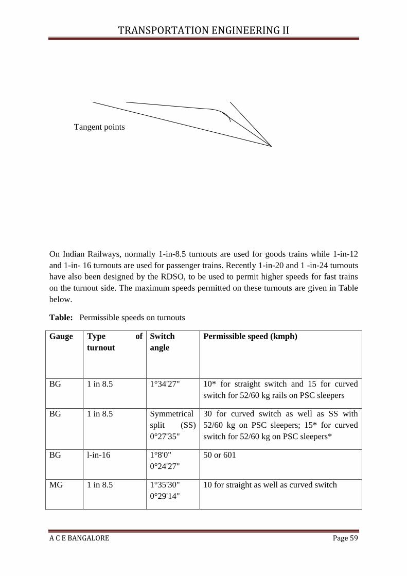


![Transportation Engineering - I - · PDF fileenough to Transportation Engineering - I nissan 3 URL: [1] INTRODUCTION TO TRANSPORTATION ENGINEERING Transportation](https://static.documents.pub/doc/80x56/5a8958357f8b9a4a268b45eb/transportation-engineering-i-to-transportation-engineering-i-nissan-3-url.jpg)
