MASTER THESIS TRANSVERSE PRESSURE DEPENDENCE OF THE CRITICAL CURRENT IN EPOXY IMPREGNATED REBCO ROEBEL CABLES Simon Otten FACULTY OF SCIENCE AND TECHNOLOGY CHAIR OF ENERGY, MATERIALS AND SYSTEMS (EMS) EXAMINATION COMMITTEE Dr. M.M.J. Dhallé Dr. J.W.J. Verschuur Prof. dr. ir. H.J.M. ter Brake DOCUMENT NUMBER - 10-10-2014
Transcript
MASTER THESIS
TRANSVERSE PRESSURE
DEPENDENCE OF THE
CRITICAL CURRENT IN
EPOXY IMPREGNATED
REBCO ROEBEL CABLES
Simon Otten
FACULTY OF SCIENCE AND TECHNOLOGY CHAIR OF ENERGY, MATERIALS AND SYSTEMS (EMS) EXAMINATION COMMITTEE
Dr. M.M.J. Dhallé Dr. J.W.J. Verschuur Prof. dr. ir. H.J.M. ter Brake
In circular particle accelerators such as CERN’s Large Hadron Collider (LHC) and Tevatron,charged particles are accelerated to speeds close to the speed of light and collided. The collisioncreates many elementary particles which are analysed using particle detectors. Particle colliderssuch as these have been very important for research in high energy physics.
During acceleration, the particles are stored in a ring of magnets: The magnetic field resultsin a Lorentz force perpendicular to the travelling direction, keeping the particle beam in a circu-lar orbit. The maximum energy of a particle stored in such a ring is limited by the magnetic fieldstrength and by the radius of the ring. To achieve higher energies, very large accelerator ringshave been constructed, of which the LHC is the biggest with a circumference of 27 km. On theother side, increasingly more powerful accelerator magnets are being developed. Here the useof superconducting materials has been crucial. When cooled below a certain critical tempera-ture, these materials have zero resistivity and can carry currents without dissipation. The use ofsuperconductors has been the only way to build magnets capable of fields well above 1 T, whilekeeping the cost and power consumption at an acceptable level.
In table 1.1, the most common superconducting materials and their critical temperatures areshown. NbTi and Nb3Sn are “low-temperature” superconductors (LTS) and need to be cooledusing liquid helium (T = 4.2 K). For a long time, these were the only materials that were usedin superconducting devices on a large scale. More recently, materials with higher critical tem-peratures were discovered. REBCO, Bi-2212 and Bi-2223 have a critical temperature above theboiling point of liquid nitrogen (T = 77 K) and are called “high-temperature” superconductors(HTS).
Table 1.1: The most common superconductors, their critical temperatures and year of discovery.
The current that a superconductor can carry without dissipation has an upper limit, thecritical current. Above this limit, the resistivity starts to increase. The critical current stronglyincreases with decreasing temperatures. For this reason, devices where a high current densityis needed, such as high-field magnets, are cooled to T = 1.9 - 4.2 K using liquid helium, even iftheir critical temperatures are much higher.
Besides temperature, the critical current depends on the magnetic field. In figure 1.1, thecritical current densities of several superconducting wires are shown as a function of the mag-netic field. For practical applications, a current density of at least 400 A/mm2 is needed [1].This means that, at 4.2 K, the maximum field of a LTS magnet is limited to 9 - 10 T for NbTiand 17 - 18 T for Nb3Sn. In order to achieve even stronger magnetic fields, HTS need to beused. Especially REBCO conductors are promising, because they can carry a sufficient currentdensity even in fields of 30 T and higher.
The magnets currently in use in the LHC storage ring are made of NbTi and have a max-imum field of 8.3 T. There are plans to upgrade these magnets. A luminosity upgrade “HighLuminosity LHC” is planned for 2020. In this project, part of the magnets will be replaced by11 - 13 T Nb3Sn magnets. For the more distant future (2030), a replacement of the entire ringby 20 T magnets is under consideration, the “High Energy LHC” [3]. Such magnets can onlybe realised with HTS materials. Alternatively, a new circular 80-100 km long tunnel may bebuilt. This project is called the Frontier Hadron Collider (FHC) [4]. The accelerator magnets inthis machine would be made of Nb3Sn or HTS cables and generate 16 or 20 T.
In the coming years, a HTS demonstration magnet is to be built at CERN in the frame ofthe EuCARD-2, which stands for “Enhanced European Coordination for Accelerator Research& Development” [5]. The aim is to generate a 5 T field standalone, and 17 T in a 13 T back-ground field. This magnet will likely be built from REBCO-based conductors in a Roebel cableconfiguration. This type of conductor and cable is explained in the next section.
6
1.2. REBCO TAPES AND ROEBEL CABLES
10
102
103
104
0 5 10 15 20 25 30 35 40 45
Who
le W
ire C
ritic
al C
urre
nt D
ensi
ty (A
/mm
², 4.
2 K)
Applied Magnetic Field (T)
YBCO: B ∥ Tape plane YBCO: B ⊥ Tape plane Bi-2212: OST NHMFL 100 bar OPBi-2223: B ⊥ Tape plane (carr. cont.) Bi-2223: B ⊥ Tape plane (prod.) Nb₃Sn: Internal Sn RRP® Nb₃Sn: High Sn Bronze Nb-Ti: LHC 1.9 KNb-Ti: LHC 4.2 KNb-Ti: Iseult/INUMAC MRI 4.22 KMgB₂: 18+1 Fil. 13 % Fill
YBCO B∥ Tape Plane
YBCO B⊥ Tape Plane
2212
High-Jc Nb3Sn
Bronze Nb3Sn
Maximal Je at 1.9 K for entire LHC NbTi strand production (CERN-T. Boutboul '07). Reducing the temperature from
4.2 K prduces a ~3 T shift in Je for Nb-Ti
4543 filament High Sn Bronze-16wt.%Sn-0.3wt%Ti (Miyazaki-
MT18-IEEE’04)
Compiled from ASC'02 and
ICMC'03 papers (J. Parrell OI-ST)
666 filament OST strand with NHMFL 100 bar Over-Pressure HT
2223: B⊥ Tape Plane
Sumitomo Electric (2012
prod.)
SuperPower "Turbo" Double Layer Tape, measured at
NHMFL 2009
MgB2: 2nd Gen. AIMI 18+1 Filaments , The OSU/ HTRI,
2013
"Carrier Controlled"
MEM'13
Nb-Ti 4.2 K LHC insertion quadruole strand
(Boutboul et al. 2006)
4.22 K High Field MRI srand (Luvata)
Nb-Ti
April 2014
Figure 1.1: Engineering (whole wire) critical current densities of different superconductingwires at liquid helium temperatures (1.9 - 4.2 K). In strong magnetic fields, the high-temperaturesuperconductors YBCO and Bi-2212 have the highest current densities. Chart by J. Lee [2].
1.2 REBCO tapes and Roebel cables
REBCO is short for Rare-Earth metal Barium Copper Oxide. It is a class of high-temperaturesuperconductors that includes compounds with different rare-earth metals. Superconductivityabove 77 K was observed for the first time in Y1.2Ba0.8CuO4, with a critical temperature of 93 K[6]. The critical current of polycrystalline REBCO, however, was initially very low due to weaklinks at the grain boundaries. A grain misalignment more than a few degrees strongly decreasesthe critical current [7]. Because of this, the powder-in-tube process is not suitable for REBCO,as in that case the micro-structure is only slightly textured. Better alignment of the grains hasbeen achieved by depositing REBCO on a textured substrate [8]. Such coated conductors havebeen commercially available since around 2005 with increasing length and quality.
Figure 1.2 shows a cross-section of a typical REBCO tape produced by SuperPower, whichis also used in all experiments described in this report. The base of the tape is a 50 µm thick
7
CHAPTER 1. INTRODUCTION
Figure 1.2: Cross section of a REBCO coated conductor from SuperPower. Image by Super-Power [9].
Hastelloy substrate, a strong alloy that provides the mechanical strength. On this substrate astack of buffer layers is deposited. The key element of the buffer is a biaxially textured layerof MgO, which is deposited using ion beam assisted deposition (IBAD). This textured layerensures good alignment of the REBCO grains that are epitaxially grown on top of it. Next,silver and copper layers are added to provide chemical protection and increase the thermalstability. The resulting tapes typically are 4 - 12 mm wide and 0.1 mm thick. The productionprocess at SuperPower is described in more detail in [10].
Magnets for big particle accelerators and AC applications (transformers and generator arma-tures) cannot be wound from a single wire. A large number of turns would be needed, resultingin a prohibitively high self-inductance. Such a magnet could be ramped only slowly and underhigh voltage, and this would complicate safe shut-down after a quench. Instead, the magnetneeds to be constructed from high-current cables consisting of 20 to 1000 wires and a smallernumber of turns [11]. Cabling methods for round superconducting wires are well developed.Unfortunately, these techniques cannot be applied to REBCO tapes because of their flat shape.
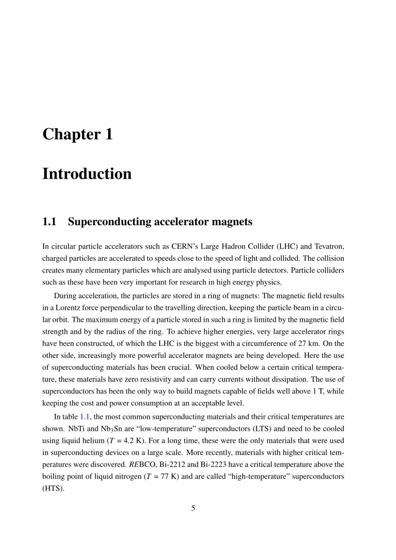
In figure 1.3 three of the most promising cabling architectures for REBCO tapes are shown:
• The Twisted-Stacked Tape Cable (TSTC) was first proposed at the Massachusetts Insti-tute of Technology. Like the name says, it is a stack of REBCO tapes that is subsequentlytwisted. The tapes can be soldered together to improve the mechanical and thermal sta-bility [12].
• The Conductor on Round Core (CORC) is developed and commercialised by AdvancedConductor Technologies. REBCO tapes are wound onto a copper or aluminium cylindri-
8
1.2. REBCO TAPES AND ROEBEL CABLES
Twisted stacked-tape cable (TSTC) [12]
Conductor on round core (CORC) [13]
Roebel assembled coated conductor (RACC)
Figure 1.3: Different cables made of REBCO coated conductors that have possible applicationsin high-field magnets.
cal former. Multiple layers can be added for higher currents [14].
• The Roebel Assembled Coated Conductor cable (RACC) is developed at Karlsruhe Insti-tute of Technology [15] and at Industrial Research Ltd [16]. REBCO tapes are punchedinto a meandering shape and assembled into a cable.
These cable concepts are still relatively new and a significant effort is ongoing to investigatetheir relative merits and drawbacks. Roebel cables have several advantages which make theman interesting candidate for AC applications and accelerator magnets: Unlike TSTC and CORCtype cables, the Roebel cable is fully transposed. In other words, all strand of the cable areequivalent, in the sense that they experience the same magnetic field along their length. Thisensures a homogeneous current distribution among the strands which is essential for the fieldhomogeneity of accelerator magnets. Secondly, Roebel cables are densely packed, especiallycompared to CORC cables, resulting in a high engineering current density. Multiple Roebelcables can be efficiently stacked in a winding pack due to their flat shape. Another advantageis high mechanical flexibility for bending in the soft direction (out-of-plane), similar to singletapes (see chapter 5). On the other hand, in-plane bending of the cable is possible only for largebending radii.
The magnetic field dependence of the critical current of REBCO tapes is highly anisotropic:a magnetic field perpendicular to the wide conductor surface has a much bigger influence than asimilar field parallel to the surface (see figure 1.1). Roebel cables retain this anisotropy, becauseall strands have the same orientation. This can be an advantage if a magnet can be designed in
9
CHAPTER 1. INTRODUCTION
such a way, that the magnetic field is always parallel to the surface.A remarkable disadvantage of Roebel cables is that more than 50% of the material is lost
in the punching process. In the future, this may be solved by punching the substrate beforedepositing the superconductor.
1.3 Transverse stresses in accelerator magnets and their ef-fect on REBCO conductors
For the EuCARD-2 demonstrator magnet, CERN is currently focusing on the option of so-calledaligned block coils from REBCO Roebel cables [17, 18]. Recent drawings are shown in figure1.4. In an aligned block coil, the wide side of the Roebel cable is parallel to the magnetic field.This orientation has two advantages: In the first place, high current densities can be achieved,as the influence of parallel magnetic field on the critical current is small. Secondly, the designrequires only little in-plane bending; Roebel cables are not very flexible in this direction.
In magnet design, the mechanical stresses due to Lorentz forces must be taken into account.The Lorentz force is perpendicular to both the current and the magnetic field. In an alignedblock coil, it will be directed perpendicularly to the wide side of the Roebel cable. Calculationshave shown that the transverse stress in the demonstrator coil can be as high as 110 MPa whenoperated in a 13 T background field [17]. In a 20 T accelerator magnet, the transverse stress
Figure 1.4: Aligned block HTS magnet designs from G. Kirby et al. [17, 18]. Feather-M0 isused for development of coil winding and quench detection, feather-M2 is the EuCARD-2 insertmagnet.
10
1.3. TRANSVERSE STRESSES IN ACCELERATOR MAGNETS AND THEIR EFFECTON REBCO CONDUCTORS
can even reach 150 MPa. It is necessary to investigate if REBCO Roebel cables can withstandthese stresses.
The next two sections provide an overview of publications on the transverse strength ofREBCO tapes and cables.
1.3.1 Transverse strength of REBCO tapes
There have been several investigations on the effect of transverse compressive stress on the crit-ical current of REBCO tapes. An overview is shown in table 1.2. For comparison, a transversestrength is defined as the stress needed to cause a critical current degradation of 5%.
The first transverse stress data were presented by J. Ekin et al. in 2001 [19]. The investigatedtapes consisted of a 100 µm thick Inconel substrate (a nickel alloy) with a 0.9 µm YBCO layer.The samples were subjected to transverse stress in a liquid nitrogen bath, while the criticalcurrent Ic was repeatedly measured. After monotonic loading the Ic degradation was less than5% at 100 MPa and 7% at 120 MPa. 2000 load cycles to 122 MPa resulted in less than 2%additional degradation.
In a study by N. Cheggour et al., REBCO tapes with pure Ni and Ni-5%W substrates weresubjected to transverse stress [20]. In the case of pure Ni substrates, a monotonic loading to120 MPa did not cause Ic degradation. However, in load-unload mode, in which the stress isreleased after each measurement, an Ic degradation of 28% was observed at 100 MPa. Thesamples which had a harder Ni-5%W substrate were found to be more tolerant to transversecompression. They showed less than 6% degradation in load-unload mode with pressures up
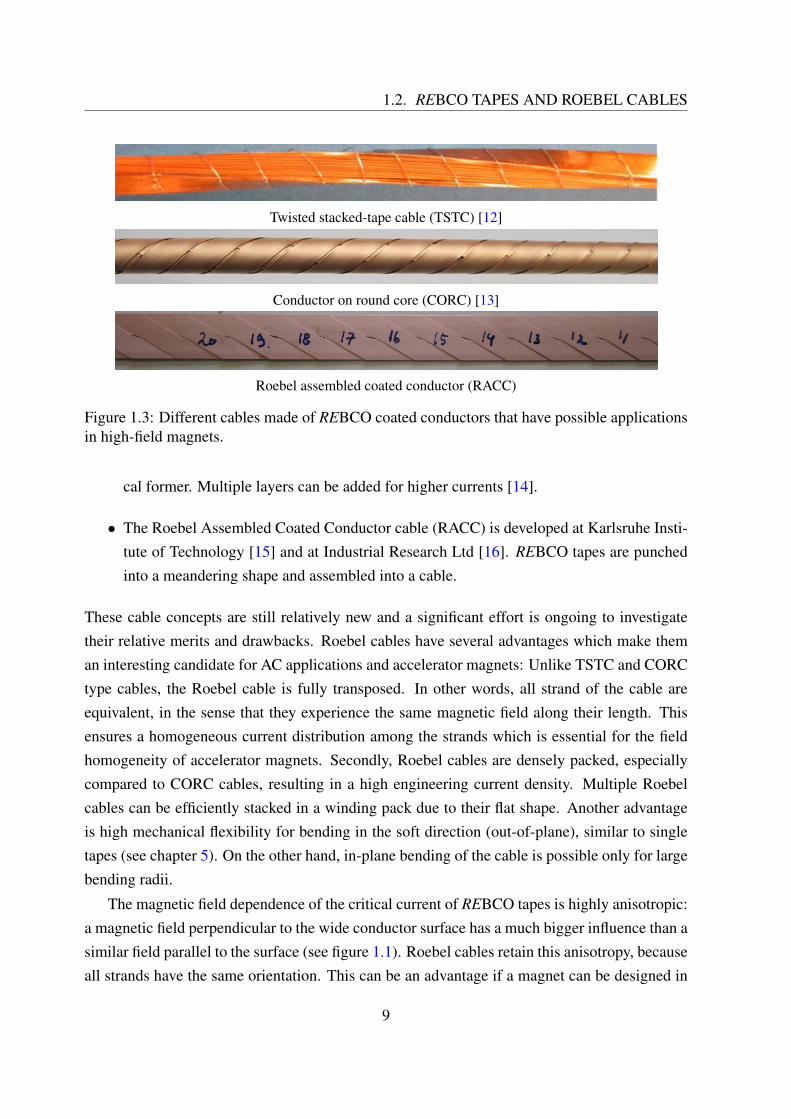
Author Year Substrate Transverse strength [MPa]
J. Ekin et al. [19] 2001 100 µm Inconel 625 100N. Cheggour et al. [20] 2003 50 µm Ni ≥ 120 (monotonic)
20 (load-unload)75 µm Ni-5%W ≥ 150
N. Cheggour et al. [21] 2007 75 µm Ni-5%W ≥ 150100 µm Hastelloy C-276 ≥ 150
T. Takao et al. [22] 2007 100 µm Hastelloy ≥ 300D. Uglietti et al. [23] 2013 50 µm Hastelloy 400L. Chiesa et al. [24] 2014 50 µm Hastelloy C-276 ≥ 450
50-75 µm Ni-5%W 440
Table 1.2: An overview of transverse stress experiments on REBCO tapes. The transversestrength is defined as the stress needed to cause a critical current degradation of 5%.
11
CHAPTER 1. INTRODUCTION
to 150 MPa. In a follow-up, REBCO tapes with Ni-5%W or Hastelloy C-276 (another nickelalloy) substrates were subjected to 20,000 fatigue cycles of transverse stresses up to 150 MPa[21]. No degradation of more than 1% was observed in any of the samples.
Monotonic loading experiments up to 400 MPa were reported T. Takao et al. [22]. All testedsamples, which had a 100 µm thick Hastelloy substrate, did not show Ic degradation at pressuresup to 300 MPa.
In 2013, D. Uglietti tested the effect of transverse stress on a commercial conductor fromSuperPower [23]. 4 mm wide tapes (SCS4050) as well as a 2 mm wide Roebel strand punchedfrom a wider tape (SCS12050) were measured. All samples had a 50 µm thick Hastelloy sub-strate. The critical current reduction was limited to 2% up to 200 MPa and to less than 8% at550 MPa for all single tape samples. These results are of special interest as the same conductoris currently used for KIT’s Roebel cables.
Recently, commercial tapes from SuperPower and AMSC were tested for use in TSTC ca-bles by L. Chiesa et al. [24]. The SuperPower tape (SCS4050-AP), which had a 50 µm Hastelloysubstrate, did not show degradation up to 450 MPa. The AMSC tape with a Ni-5%W substrate(344C) showed a slow degradation up to 13% at 480 MPa.
1.3.2 Transverse strength of Roebel cables
REBCO tapes should easily be able to withstand the transverse stresses up to 150 MPa in apossible HTS accelerator magnet. In cable configurations, however, the stress may not have ahomogeneous distribution over the entire surface. The stress at certain locations can be muchhigher than the average, and cause local damage.
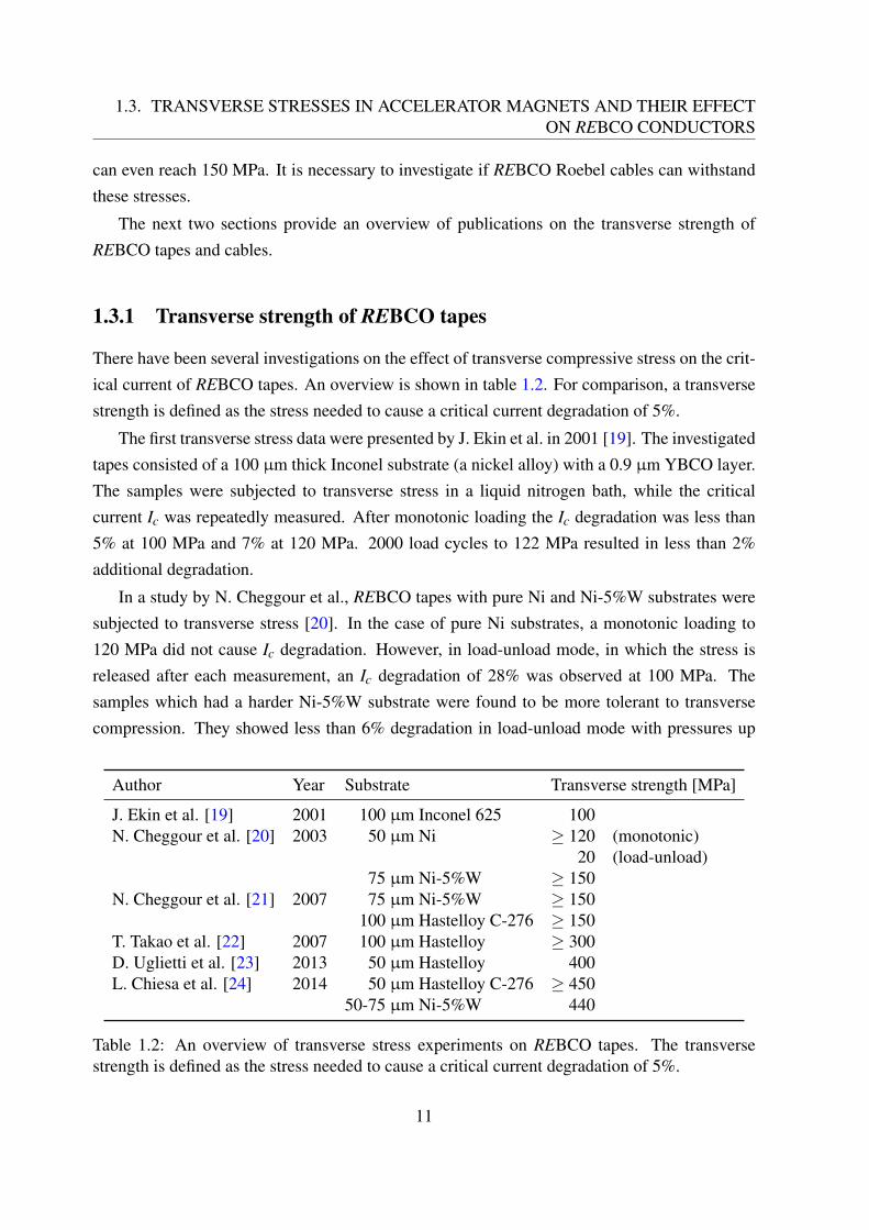
J. Fleiter et al. subjected REBCO Roebel cables manufactured by General Cable Supercon-ductors (GCS) and KIT to transverse stresses [25]. Both cables were 12 mm wide. Duringcompression, the cables were stacked with a pressure sensitive film from Fujifilm. This filmbecomes red when a pressure more than 40 - 50 MPa is applied. In figure 1.5, the stress patternsat 40 MPa are shown for two different Roebel cables. From the prints, the effective section thatexperiences transverse stress is estimated to be only 36% for the GCS cable and 23% for theKIT cable. This means that loading to 40 MPa leads to a local stress of at least 111 MPa for theGCS cable and 167 MPa for the KIT cable.
The cables were further loaded up to 45 MPa. Afterwards, the cables were disassembledand several strands were analysed at 77 K. No irreversible Ic degradation was observed [25].
Another transverse pressure test on Roebel cables was reported by Uglietti et al. [23]. Thecables samples were provided by GCS and had a width of 4 mm. The strands of the cable
12
1.3. TRANSVERSE STRESSES IN ACCELERATOR MAGNETS AND THEIR EFFECTON REBCO CONDUCTORS
Figure 1.5: Roebel cables and corresponding stress patterns measured by J. Fleiter et al. [25].(a) and (b) show a Roebel cable from General Cable Superconductors (GCS), (c) and (d) a cablefrom KIT.
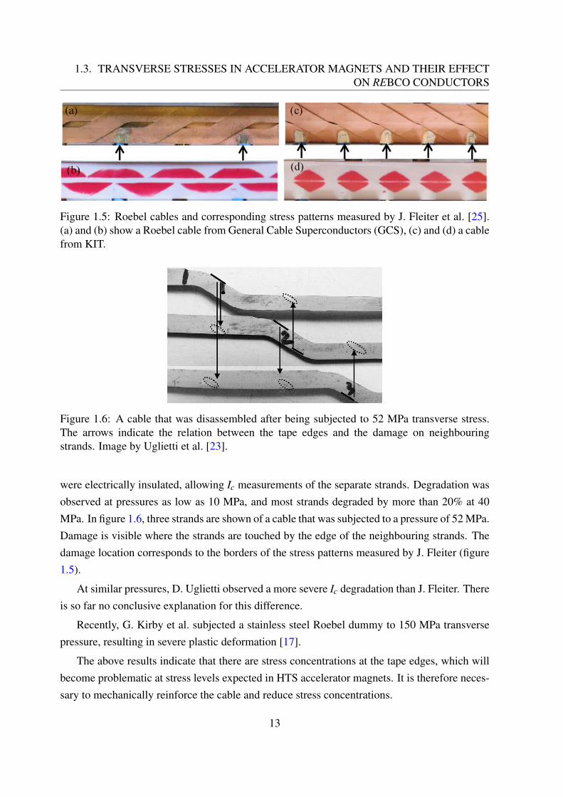
Figure 1.6: A cable that was disassembled after being subjected to 52 MPa transverse stress.The arrows indicate the relation between the tape edges and the damage on neighbouringstrands. Image by Uglietti et al. [23].
were electrically insulated, allowing Ic measurements of the separate strands. Degradation wasobserved at pressures as low as 10 MPa, and most strands degraded by more than 20% at 40MPa. In figure 1.6, three strands are shown of a cable that was subjected to a pressure of 52 MPa.Damage is visible where the strands are touched by the edge of the neighbouring strands. Thedamage location corresponds to the borders of the stress patterns measured by J. Fleiter (figure1.5).
At similar pressures, D. Uglietti observed a more severe Ic degradation than J. Fleiter. Thereis so far no conclusive explanation for this difference.
Recently, G. Kirby et al. subjected a stainless steel Roebel dummy to 150 MPa transversepressure, resulting in severe plastic deformation [17].
The above results indicate that there are stress concentrations at the tape edges, which willbecome problematic at stress levels expected in HTS accelerator magnets. It is therefore neces-sary to mechanically reinforce the cable and reduce stress concentrations.
13
CHAPTER 1. INTRODUCTION
1.4 Work overview
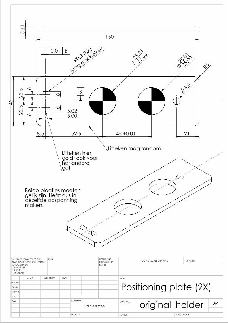
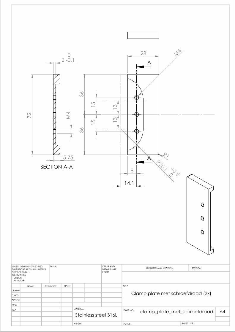
The goal of this master assignment is to investigate whether epoxy impregnation can reducesuch stress concentrations and thus prevent critical current degradation at stress levels up to150 MPa. To fulfil the assignment, these separate issues have to be addressed: an impreg-nation material and method need to be selected; a suitable sample holder needed needs to bedesigned, in particular the minimum bending radius of the investigated Roebel cables has to bedetermined; and the critical current of an impregnated cable sample needs to be measured atdifferent transverse stress levels.
These different activities are reflected in the structure of this report:
Chapter 2: General experimental methodsThis chapter discusses the preparation of Roebel cables and the general method used tomeasure their critical currents.
Chapter 3: Impregnation materialsAn overview of impregnation materials is given, and their suitability for application inRoebel cables is discussed. The relevant low-temperature properties of several commer-cially available resin systems are measured. Based on these results, an epoxy resins filledwith fused silica powder is selected as the most suitable material.
Chapter 4: Vacuum impregnationThe vacuum impregnation of dummy cables is described. The impregnation quality isevaluated using microscopic images of cable cross-sections. In this way, the impregnationprocess is improved without wasting expensive REBCO cables.
Chapter 5: Out-of-plane bending of REBCO Roebel cablesThis chapter reports on measurements of the minimum bending radius for Roebel cables.These measurements are needed for the design of the sample holder for the transversepressure tests.
Chapter 6: Transverse strength of a REBCO Roebel cableThe test of an impregnated Roebel cable in a transverse press set-up is described.
This project was done within a cooperation between Karlsruhe Institute of Technology(KIT), where Roebel cables are developed, and Twente University (UTwente), which has fa-cilities for mechanical tests of superconducting cables. The work described in chapters 3, 4 and5 was done at KIT, the pressure tests described in chapter 6 were done at UTwente.
14
Chapter 2
General experimental methods
The aim of this short chapter is to explain experimental aspects that are referred to throughoutthe report. The production method and layout of REBCO Roebel cables as well as the electricalanalysis of those cables are discussed.
2.1 REBCO Roebel cable preparation
First, the superconducting tape is punched into a meandering shape using a pneumatic punchingmachine (figure 2.1). The machine has two knives which can remove material from each side ofthe tape. A reel-to-reel system is used to automatically move the tape. The accuracy of the cuts
Figure 2.1: Computer controlled pneumatic punching machine that is used at KIT. It can beused to make Roebel strands of 4, 10 and 12 mm wide tapes with different transposition lengths.Image by W. Goldacker et al. [15].
15
CHAPTER 2. GENERAL EXPERIMENTAL METHODS
is better than 50 µm [26]. After punching, the conductor has lost more than half of its criticalcurrent. Relative to the tape width, however, the critical current reduction is less than 3%. Thisindicates that the machine does little damage to the remaining part [26].
The machine is suitable for 4, 10 and 12 mm wide tapes. The standard transposition lengthsare 115.7 mm for 4 mm wide tapes, and 126, 226, and 426 mm for 12 mm wide tapes. Forthis project, 12 mm wide tapes are punched with 126 mm transposition length. The punchingpattern with dimensions is shown in figure 2.2.
Transposition length: 126 mm
30Outer radius: 0 mm
Inner radius: 10 mm
5.5 mm
5.5 mm
12 mm
Figure 2.2: Shape of the Roebel strands after punching. The figure shows one transpositionlength in real size.
After punching, strands of the desired length are cut from the tape. The critical current ismeasured at 77 K (section 2.2) to check for any defects. If no defects are found, the strands areassembled into a cable by hand. All cables in this project consist of ten strands which all havethe same orientation of the REBCO-coated side.
Figure 2.3: Computer drawing of an assembled Roebel cable, showing seven out of ten strands.Cross-sections are shown at the bridge (B) and between two bridges (A). The thickness of thetapes is exaggerated to better show the 3D structure. Image by W. Goldacker et al. [15].
16
2.2. ELECTRICAL CHARACTERISATION
2.2 Electrical characterisation
The goal of electrical characterisation is to determine the critical current and the n-value of thesample. The electric field E and the current I in a one-dimensional superconducting wire areoften described by a power law:
EEc
=
(IIc
)n
(2.1)
In this equation, Ic is the critical current, which is defined as the current at which the electric fieldreaches a certain criterion Ec. In this report a criterion of Ec = 10−4 V/m is used, as is usualfor HTS conductors. The n-value describes the steepness of the superconducting transition,with n = 1 being a resistor and n = ∞ being an idealised superconductor. It is widely used as ameasure of superconductor quality as it reflects both magnetic flux pinning and micro-structuralhomogeneity.
0 0.2 0.4 0.6 0.8 1 1.20
0.5
1
1.5
I/Ic
E/E
c
n = 1n = 10n = 25
Figure 2.4: Superconducting transition for different n-values.
For electrical characterisation, the current-voltage characteristic is measured. This usuallydone by passing an increasing current through the sample and measuring the voltage over a well-defined length. The voltage is always measured with a separate pair of wires, connected at somedistance from the current leads. This is done to avoid measuring the voltage associated with theresistive current contacts. In case of a cable consisting of multiple strands, the contacts arealways connected to the same strand, to exclude potential differences between different strands.As the electric field criterion is relatively low, sensitive nano-voltmeters or pre-amplifiers needto be used.
17
CHAPTER 2. GENERAL EXPERIMENTAL METHODS
The power law (equation 2.1) can be written as a linear relation between ln(I) and ln(E):
ln(
EEc
)= ln
((IIc
)n)(2.2)
⇒ ln(E) =n ln(I)+ ln(Ec)−n ln(Ic) (2.3)
To compute the critical current and the n-value, a linear fit is made. The n-value is equal tothe slope. The critical current is determined from the n-value and the intercept with the verticalaxis.
18
Chapter 3
Impregnation materials
3.1 Introduction
Epoxy resins are commonly used for reinforcement of resistive and low-temperature super-conducting coils. These resins are processed by mixing two liquid parts (resin and hardener),followed by a curing cycle to harden it. As a liquid, uncured epoxy resin fills up small spacesinside a coil. It is applied using techniques such as wet-winding or vacuum impregnation. Ad-ditionally, most epoxy resins have good dielectric and mechanical properties.
In REBCO coils, however, epoxy impregnation has been challenging: the first reportedimpregnated coils showed degradation of the critical current. After visual inspection of animpregnated coil, a separation of the layers (delamination) was observed by T. Takematsu [27].Such damage is explained as a result of a mismatch in thermal expansion between the conductorand the epoxy: When epoxy is cooled down from room temperature to T = 4.2 K, it contractsby 1.33%, while the REBCO tape contracts by only 0.25% [28]. This mismatch leads to tensilestresses perpendicular to the tape; in other words, the layers of the tape are being pulled apart.REBCO tapes are very sensitive to such stresses, and degradation can occur at stress levels aslow as 10 MPa [29, 30].
Several different methods to reduce tensile stresses have been proposed and tested success-fully. The underlying principles are the following:
• Using no impregnation at all. This is possible in stacked cables and pancake coils, sincethe rectangular tapes form a good support themselves. Co-winding with an insulated steeltape has been done for additional support and electrical insulation between the windings[31].
• Avoiding epoxy penetration in between the winding and casing only the entire coil. By
19
CHAPTER 3. IMPREGNATION MATERIALS
winding a pancake coil under high tension the tapes can be very closely packed. Epoxyimpregnation of such a coil did not cause damage [32].
• Using a soft impregnation material. Beeswax and paraffin have been used to impregnateREBCO pancake coils [27, 33]. Despite their high thermal contraction, these materialsare too weak to build up high thermal stresses during cool-down; they crack instead.
• Using an impregnation material with low adhesive strength. Both beeswax and paraffindo not stick to metals. Cyanoacrylate resin does stick, but it still has a bonding strengthseveral times lower than epoxy. A coil impregnated with this material did not show anydegradation [34].
• Introducing a weak mechanical barrier between the conductor and the epoxy that absorbsthe stress. This has been done by sticking the conductor in a polyester heat-shrink tube[35], and by coating it with a polyimide layer [36]. Both coils were then epoxy impreg-nated without any degradation.
• Using materials with low thermal expansion. Epoxy resins can be mixed with a powderof a low thermal-expansion material in order to decrease the overall thermal expansion.In a previous work at KIT, a Roebel cable was impregnated with a 1:1 mixture of epoxyand silica [28]. The critical current of the cable was measured at 77 K before and afterimpregnation, and no degradation was observed.
• Polyimide resins show a thermal contraction lower than epoxy even without any fillers[37]. Moreover, they are more resistant against radiation than epoxy [38], making them apromising candidate for impregnation of accelerator magnets. A bismaleimide resin hasbeen used on a Nb3Sn cable stack, which had decreased thermal contraction comparedto one impregnated with epoxy [38]. However, such resins have not been applied yet toREBCO coils and cables.
In order to reinforce Roebel cables and reduce stress concentrations under transverse load-ing, it is essential that the cable, and in particular the central hole, is filled with a strong material.The impregnation should prevent any movement of the wires, even under high pressures. Softimpregnation materials such as beeswax and paraffin are therefore not suitable. Likewise, weakmechanical barriers surrounding the tapes are undesirable as they allow for some movement.Using such a barrier around the entire cable is also not an option, as the cable itself would notbe filled.
20
3.2. TESTED FILLED EPOXY RESINS
When choosing an impregnation material, one also needs to make some practical consid-erations. Both at UTwente and KIT basic equipment is available for vacuum impregnationwith epoxy. Epoxy resins are generally processed at moderate temperatures ranging from roomtemperature to 100 C, and maintaining this temperature is not critical. Polyimide resins needhigher temperatures of 120 - 200 C, and have a viscosity that strongly depends on temperature.This complicates the impregnation procedure; for example, syringes cannot be used to move theresin, as it will freeze in the tip and clog it. For this project we decided to stick to epoxy resinsbecause of their ease of processing and proven good mechanical properties. Even so, polyimideresins remain an attractive alternative.
Many filled epoxy resins are commercially available, but their properties at low temperaturesare not well-documented. In this chapter, epoxy resins with six different fillers are analysedspecifically for low-temperature use. Their thermal expansion, thermal conductivity and elec-trical conductivity are measured for temperatures ranging from 4.2 to 300 K. Using the results,the most suitable resin is selected.
3.2 Tested filled epoxy resins
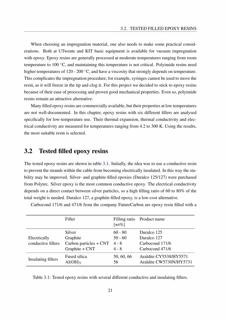
The tested epoxy resins are shown in table 3.1. Initially, the idea was to use a conductive resinto prevent the strands within the cable from becoming electrically insulated. In this way the sta-bility may be improved. Silver- and graphite-filled epoxies (Duralco 125/127) were purchasedfrom Polytec. Silver epoxy is the most common conductive epoxy. The electrical conductivitydepends on a direct contact between silver particles, so a high filling ratio of 60 to 80% of thetotal weight is needed. Duralco 127, a graphite-filled epoxy, is a low-cost alternative.
Carbocond 171/6 and 471/6 from the company FutureCarbon are epoxy resin filled with a
Table 3.1: Tested epoxy resins with several different conductive and insulating fillers.
21
CHAPTER 3. IMPREGNATION MATERIALS
mixture of carbon particles and single-walled carbon nanotubes (CNT). The carbon nanotubesprovide a percolation path for the current even at very low filling ratios [39]. Resins with lessfiller have lower viscosity and are more easily processed. Carbon nanotubes also have beenshown to increase thermal conductivity [40] and improve the mechanical properties [41]. Dataon the thermal expansion of these mixtures was however not available, so we decided to measureit for two commercially available ones.
As discussed below, it was found that these conductive epoxy resins are not suitable for theimpregnation of Roebel cables. Two additional insulating resins were offered for testing byHuntsman Corporation. Araldite CY5538 with hardener HY5571 is supplied unfilled. As filler,fused silica flour “Silbond FW600 EST” with a median grain size of 4 µm is used. Fused silicahas a low coefficient of thermal expansion of 0.5∗10−6 K−1 [42]. Araldite CW5730N is a resinpre-filled with 56 wt% aluminium hydroxide.
3.3 Thermal expansion
All filler materials investigated have a coefficient of thermal expansion much lower than epoxy(see table 3.2). Addition of these materials to the resin is therefore likely to reduce the overallthermal expansion. The thermal expansion of the filled epoxy resins were measured in theCryogenic Material Test Facility Karlsruhe (CryoMaK) [43]. The measurements were done byNadezda Bagrets.
Table 3.2: Coefficients of linear thermal expansion at room temperature for the investigatedfiller materials and unfilled epoxy.
3.3.1 Method
Samples are prepared by mixing the resin and hardener according to the instructions and curingin a Teflon form. The resulting samples have a size of 60 mm × 10 mm × 5 mm.
22
3.3. THERMAL EXPANSION
To measure the elongation of the sample, two extensometers are attached to the sample (fig-ure 3.1). The extensometers consist of U-shaped bars of copper-beryllium. The sharp endsof the extensometer are fixed to the sample using steel clamps. On both extensometers straingauges are attached which have a resistance dependent on the deformation. To obtain an accu-rate relation between the extension at the tips and the strain gauge resistance, the extensometershave been calibrated using a tensile machine. This calibration was done at different tempera-tures, as the calibration factor depends on the temperature.
The sample and extensometers are inserted into a cryostat and cooled to 4.2 K by fillingthe cryostat with liquid helium. Once the helium has evaporated, the temperature inside thecryostat slowly rises to room temperature in about ten hours. The slow temperature changeensures a homogeneous temperature in the sample area. During these ten hours, the strain gaugeresistance is continuously measured. The temperature is measured as well using a Lakeshorecryogenic temperature sensor.
A correction needs to be made to compensate for the thermal expansion of the extensometeritself. For this reason, the measurement is repeated with a sample of Zerodur glass of which thethermal expansion is negligible. The difference in thermal expansion between the Zerodur andthe actual sample measurements is taken as the final result.
23
CHAPTER 3. IMPREGNATION MATERIALS
3.3.2 Results
The total linear thermal expansion when cooling from room temperature to T = 4.2 K is shownin figure 3.2. The thermal expansion of an unfilled epoxy (Araldite DBF), alumina-filled epoxy(Stycast 2850 FT) and REBCO tapes were measured before for a different project using thesame equipment [28]. These values are added to the figure for comparison.
Unfilled epoxy *
Carbon particles + CNT (4 - 8 %)
Graphite+ CNT (4 - 8 %)
Al(OH)3
(56 %)
Silver (60 - 80 %)
Silica (50 %)
Silica (60 %)
Graphite(50 - 60 %)
Alumina (60 - 70 %) *
REBCO tape *0.0
−0.5
−1.0
−1.5 −1.35−1.18−1.11−1.11−1.04
−0.82
−0.60−0.58−0.50
−0.27The
rmal
expa
nsio
n[%
]
Figure 3.2: Thermal expansion for T = 293→ 4.2 K for different filled epoxies. (*) The valuesfor unfilled epoxy, alumina-filled epoxy and REBCO tape were taken from Barth et al. [28].
The thermal expansion of unfilled epoxy is five times larger than that of REBCO tape. Allfillers decrease the thermal expansion to some degree. The mixtures with the lowest thermalexpansions are heavily filled with silica, graphite, or alumina. This makes sense because silica,graphite and alumina are themselves materials with low thermal expansion.
3.4 Thermal conductivity
Apart from thermally induced stresses, another point of attention is the thermal conductivityof the impregnation mixture. A too low thermal conductivity will hamper heat removal tothe environment and thus may endanger the thermal stability of the cable. For applications attemperatures above 0 C, epoxy resins are commonly filled with silica, alumina or silver if anincreased thermal conductivity is desired. But like many other material properties, the thermal
24
3.4. THERMAL CONDUCTIVITY
conductivity changes with temperature. In this section, the thermal conductivity of several filledresins is analysed at cryogenic temperatures.
The thermal conductivity is measured in a Physical Property Measurement System (PPMS)from Quantum Design [47]. The setup features a 14 T magnet and a variable temperaturecryostat for temperatures ranging from 1.9 to 400 K. The measurements described in this sectionwere done by Sandra Drotziger and Nadezda Bagrets.
3.4.1 Method
The measurements principle is as follows: a known heat flux P is passed through the sample,which has a constant cross-sectional area A over its length. At the same time, the temperaturedifference ∆T is measured over a distance ∆x parallel to the heat flow. The thermal conductiv-ity k can then be calculated by dividing the heat flux density P/A by the temperature gradient∆T/∆x:
k =P∆xA∆T
(3.1)
This method assumes a steady state; the temperature of the sample does not change in time.Samples for the thermal conductivity measurements were cut from the larger thermal ex-
pansion samples. The new smaller samples are cylinders with a diameter of 6 mm. Cylinderswith two different lengths (2 and 3 mm) were made from each resin. The measurements arerepeated on these three samples and compared to rule out geometry effects.
Figure 3.3: CryoMaK thermal conductivity measurement setup. Image by Bagrets et al. [48].
To establish a heat flux through the sample, one side of the sample is connected to a resistiveheater using silver epoxy. The other side is glued to a thermal sink. Two temperature sensorsare glued in between the heater and the sink. Next, the samples are inserted into a temperaturevariable cryostat. The chamber is evacuated to approximately 10−6 mbar to prevent heat transferto the surrounding gas. Using the heater a temperature increase of 1 - 3% of the backgroundtemperature is created. Heat losses due to radiation are automatically estimated by the PPMSsoftware.
25
CHAPTER 3. IMPREGNATION MATERIALS
A more detailed discussion of the thermal conductivity measurements at CryoMaK can befound in [48].
3.4.2 Results
The results of these measurements are shown in figure 3.4. The two samples of each resin showsimilar behaviour, indicating that the influence of geometry is small.
Three bar diagrams in figure 3.4 show the thermal conductivities at the most relevant cryo-genic temperatures 77 K and 4.2 K. The values for unfilled, silica-filled (Araldite DBF) andalumina-filled (Stycast 2850 FT) epoxy resins are shown for comparison [49, p. 83]. Thesemeasurements were done in the same setup and are in agreement with literature values [50, 51].At room temperature, all fillers increase the thermal conductivity, up to a factor 16 for the silverfiller. At cryogenic temperature, however, this effect is much smaller. The thermal conductivi-ties of the different epoxy resins at 4.2 K differ by no more than a factor four. For fillers otherthan silver the difference is even reduced to less than a factor two. These fillers will thereforehave limited use for improving the stability of magnets operated at 4.2 K.
Figure 3.4: Thermal conductivity as a function of temperature for the different filled epoxyresins. Values with * are from C. Barth’s thesis [49].
27
CHAPTER 3. IMPREGNATION MATERIALS
3.5 Electrical resistivity
At cryogenic temperatures, the specific heat of most materials is much lower than at roomtemperature. A relatively small amount of heat can therefore cause a large rise in temperature. Ifthe temperature of a superconductor rises above the critical temperature a “quench” occurs: thesuperconductor suddenly enters its normal (resistive) state. If the subsequent resistive heatingis lower than the cooling power, the superconductor can recover from the quench. Otherwise,the normal zone will become larger and larger and the current needs to be stopped. The energyneeded to cause a quench is called the minimum quench energy. The higher the minimumquench energy, the better the thermal stability of the cable.
In a cable, multiple superconducting strands are connected in parallel. Suppose that oneof those strands quenches and develops a normal zone. If the strands are electrically insulated(high inter-strand resistance), the current is forced to flow through the normal zone. If the inter-strand resistance is sufficiently low, the current can relocate to other strands of the cable. Inthis case, less current flows through the normal zone leading to a lower resistive heating. Anincreased minimum quench energy was shown for NbTi [52] and Nb3Sn Rutherford cables [53]with a low inter-strand resistance.
If epoxy impregnation electrically insulates the strands, it can have an adverse effect onthe thermal stability. Impregnation with a conductive silver-filled epoxy has been proposedfor Roebel cables [54]. A cable impregnated with such material had a decreased inter-strandresistance compared to the one impregnated with unfilled epoxy. The effect on the thermalstability however has not been analysed yet.
In this work epoxy resins are analysed of which four have an electrically conductive filler.The electrical conductivity of those resins at low temperatures are described in this section. Themeasurements were done by Sandra Drotziger.
3.5.1 Method
For these measurements, new 4 mm × 4 mm × 15 mm samples were prepared. A small plugwith four contacts in a line was inserted into the resin before it hardened. The two outer polesare connected to a current source which provides a current of a few mA through the sample.The voltage is measured over the inner two poles. The resistivity is then computed using thewell-known formula
ρ =Al
R =AUlI
(3.2)
28
3.5. ELECTRICAL RESISTIVITY
in which A is the cross-sectional area and l is the distance between the two voltage contacts.The measurement is repeated at different temperatures in the temperature-variable cryostat ofthe PPMS.
3.5.2 Results
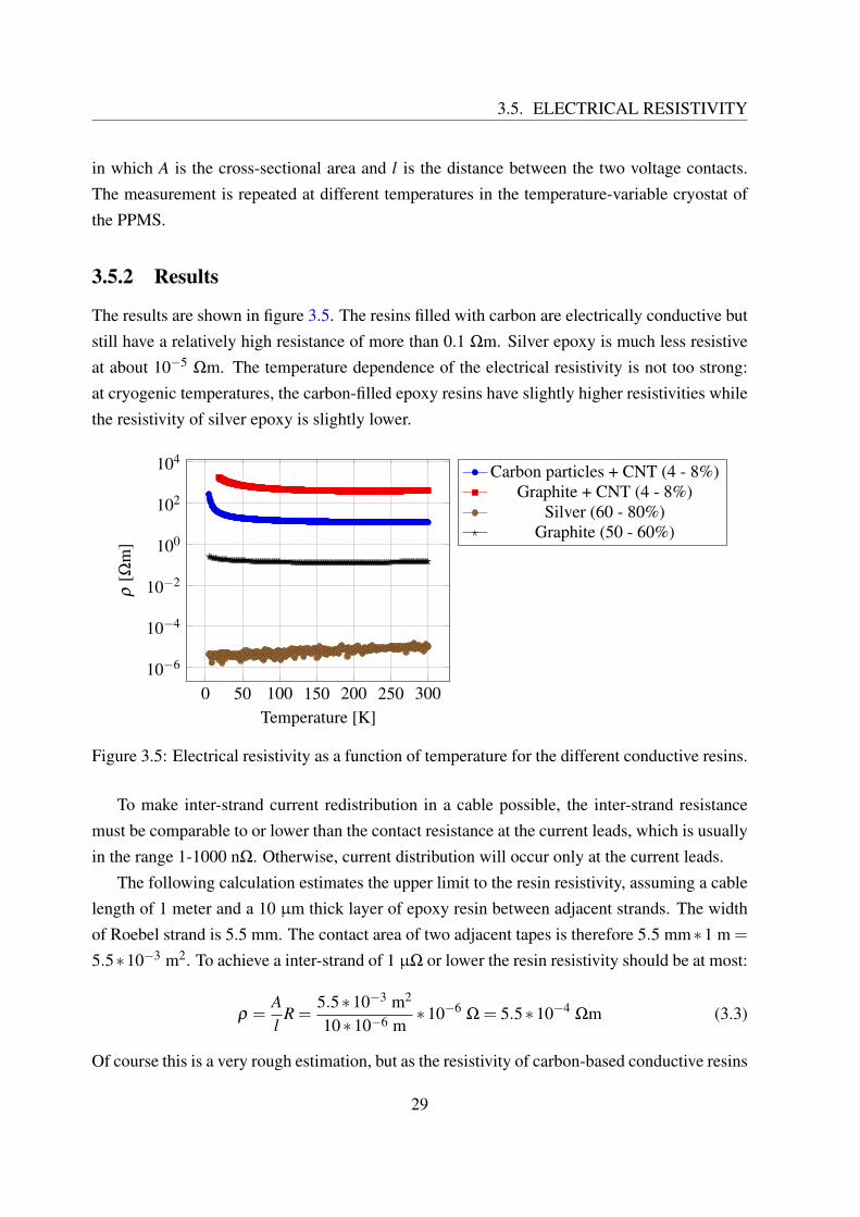
The results are shown in figure 3.5. The resins filled with carbon are electrically conductive butstill have a relatively high resistance of more than 0.1 Ωm. Silver epoxy is much less resistiveat about 10−5 Ωm. The temperature dependence of the electrical resistivity is not too strong:at cryogenic temperatures, the carbon-filled epoxy resins have slightly higher resistivities whilethe resistivity of silver epoxy is slightly lower.
Figure 3.5: Electrical resistivity as a function of temperature for the different conductive resins.
To make inter-strand current redistribution in a cable possible, the inter-strand resistancemust be comparable to or lower than the contact resistance at the current leads, which is usuallyin the range 1-1000 nΩ. Otherwise, current distribution will occur only at the current leads.
The following calculation estimates the upper limit to the resin resistivity, assuming a cablelength of 1 meter and a 10 µm thick layer of epoxy resin between adjacent strands. The widthof Roebel strand is 5.5 mm. The contact area of two adjacent tapes is therefore 5.5 mm∗1 m =
5.5∗10−3 m2. To achieve a inter-strand of 1 µΩ or lower the resin resistivity should be at most:
ρ =Al
R =5.5∗10−3 m2
10∗10−6 m∗10−6
Ω = 5.5∗10−4Ωm (3.3)
Of course this is a very rough estimation, but as the resistivity of carbon-based conductive resins
29
CHAPTER 3. IMPREGNATION MATERIALS
is 3 to 7 orders of magnitudes larger, they are not suitable for this purpose. On the other hand,silver-filled epoxy resins may have sufficient conductivity to allow current redistribution.
3.6 Chemical compatibility
When REBCO tapes are punched into Roebel strands, the copper sheath is removed on oneside. At this spot the REBCO layer comes in direct contact with the resin during impregnation.Some epoxy resins contain corrosive components that can cause damage. For example, one ofthe Stycast hardeners has been shown to dissolve the REBCO layer [55].
To rule out any chemical problems, the chemical compatibility of the separate epoxy com-ponents (resin and hardener) was tested. 10 cm long samples of conductor were used of whichthe copper edges had been removed by laser cutting. The samples were submerged in 10 ml ofthe component in a test tube for approximately 16 hours. The critical currents before and afterexposure to the component were compared. No degradation was observed for the Carbocondand Araldite resins and hardeners. The Duralco resins were not tested because only a smallamount was available.
In a future production method for Roebel cables, the copper stabilizer may be added afterpunching. In this case there is no direct contact between resin and superconductor, and chemicalattack is no longer an issue.
3.7 Recommendation for Roebel cables
To achieve a large reduction in thermal expansion, the epoxy resin must be heavily filled (>50 wt%) with low-CTE fillers. The lowest thermal expansions were indeed observed in thegraphite- and fused silica-filled resins.
For impregnation purposes, there is another quantity that is important, and that is the pro-cessing viscosity: Adding particles to a resin strongly increases the viscosity and this impedesepoxy flow into the open spaces within the cable. The viscosities according to the datasheetsare listed in table 3.3. Both the silver and the graphite-filled resins (Duralco 125/127) are heav-ily filled with particles and are a paste-like substance. The viscosity of these resins is too highfor them to be used for cable impregnation. The tested resins filled with fused silica (AralditeCY5538) and Al(OH)3 (Araldite CW5730N) are also heavily filled. However, these resins canbe processed at an elevated temperature of 60 - 100 C, while retaining a pot-life of severalhours. In this way the viscosity is lowered and the heavily filled resin is suitable for impregna-tion.
Table 3.3: Tested epoxy resins with the measured linear thermal expansion and processingviscosity according to the datasheet. The temperature in brackets denotes the correspondingprocessing temperature. Values in red are problematic for application to REBCO tapes.
The only resin that combines a low thermal expansion with low processing viscosity isAraldite CY5538/HY5571 with fused silica, and therefore it is the most suitable for impregna-tion of the Roebel cable.
In this chapter, six commercially available epoxy resins have been analysed. All but AralditeCY5538 are supplied pre-filled. Because of this, we cannot know exactly what and how muchfiller is inside. In addition to the filler material, the particle size and shape may also differ.Moreover, epoxy resins come in many different kinds for different purposes, all of which havedifferent properties. One should therefore be careful when making comparisons. The conclu-sions made in this chapter do not generally apply to all epoxy resins with a specific filler. Theyare just a recommendation for the most suitable system out of the six tested.
31
Chapter 4
Vacuum impregnation
4.1 Introduction
To attain good reinforcement, all gaps in the cable or coil need to be filled with resin. Remain-ing gas bubbles in the cable or coil are highly undesirable, because they can lead to an inho-mogeneous stress distribution. There are in principle two methods to do this: the wet-windingprocess, in which the resin is added to the cable just before coil winding, and vacuum impreg-nation, in which the resin is inserted into the coil after winding. Optionally, the cable can bestuck into a glass-fibre sleeve before impregnation. The resulting glass-fibre epoxy compositeprevents successive windings from touching each other and thus provides electrical insulationbetween them.
Initially, we tried impregnation of a dummy cable using a simple method resembling wet-winding. The cable was stuck into a glass-fibre sleeve, and epoxy resin was added to the cablein a straight Teflon mould. Next, the cable was cycled to low pressure in a vacuum chamber,which should help air bubbles to escape. Earlier, a similar method had been used successfullyon a less densely packed Roebel cable from General Cable Superconductors [28]. After curing(hardening) of the resin, cross-sections of the cables were made by cutting the cable in twowith a diamond wire saw and polishing the sawed surface. The cross-sections were analysedwith an optical microscope to check the impregnation quality. Cables impregnated in this wayalways ended up looking like the one in figure 4.1. There are air bubbles between the strandsand the central hole is not totally filled. It is probably the geometry of the Roebel cable withmany narrow openings and a relatively large open volume in the centre that allows air to remaintrapped. From these try-outs its was concluded that wet-winding is not suitable for these denselypacked Roebel cables.
33
CHAPTER 4. VACUUM IMPREGNATION
Figure 4.1: Cross-section of a cable impregnated by wet-winding, followed by cycling to lowpressure in a vacuum chamber. The impregnation quality is poor: there are voids in the centralhole and between the strands.
4.2 Vacuum impregnation principle
A more powerful method to get resin inside the cable is vacuum impregnation. The processconsists of four basic steps (figure 4.2). A vacuum chamber is needed with the epoxy resin andthe sample inside. First, the chamber this evacuated, removing all air from the sample. Next, thesample is submerged into the resin, and after some time the chamber is pressurised. This is thekey step: the pressure pushes the resin into all openings of the cable that have not been filled yetby gravity or capillary suction. Any remaining gas bubble will shrink to a small fraction of itssize. In our set-up, the atmospheric pressure is used, simply by opening the vacuum chamber.In more advanced set-ups, higher pressures can be used. Finally, the sample can be removedfrom the resin and cured.
34
4.2. VACUUM IMPREGNATION PRINCIPLE
6
Epoxy resin
Air P = 0.3 kPa
Epoxy resin
Air P = 0.3 kPa
Epoxy resin
Air P = 100 kPa
Pressure
Epoxy resin
Air P = 100 kPa
(a) Evacuate the chamber.
6
Epoxy resin
Air P = 0.3 kPa
Epoxy resin
Air P = 0.3 kPa
Epoxy resin
Air P = 100 kPa
Pressure
Epoxy resin
Air P = 100 kPa
(b) Submerge the sample.
6
Epoxy resin
Air P = 0.3 kPa
Epoxy resin
Air P = 0.3 kPa
Epoxy resin
Air P = 100 kPa
Pressure
Epoxy resin
Air P = 100 kPa
(c) Pressurise the chamber.
6
Epoxy resin
Air P = 0.3 kPa
Epoxy resin
Air P = 0.3 kPa
Epoxy resin
Air P = 100 kPa
Pressure
Epoxy resin
Air P = 100 kPa
(d) Remove the sample.
Figure 4.2: Vacuum impregnation in four steps.
35
CHAPTER 4. VACUUM IMPREGNATION
4.3 Vacuum impregnation set-up
A small impregnation set-up was already available at KIT which had been used for impregna-tion of REBCO pancake coils with beeswax. This set-up was modified to make it suitable forimpregnation of Roebel cables (see figure 4.3). The cable is fixed on the U-shaped outer surfaceof a Teflon sample holder, which has the same shape as the sample holder for the mechanicalpress at UTwente. The sample holder is fixed to the top flange of the vacuum chamber. Be-low the sample holder, there is a brass resin container that can be moved up and down fromthe outside by a steel rod. In this way, the sample can be submerged into the resin in vacuumconditions, without opening the chamber. Inside the container is a thermocouple necessary forcontrolling the resin temperature. The sample holder and resin container are inserted into thevacuum chamber, a glass tube of which the lower part is heated by an oven. The pressure in thechamber is controlled manually using a vacuum pump, a valve and a pressure sensor.
Movable resin
container
Sample holder
Thermocouple
Oven
Vacuum
pump
Pressure
sensor
Temperature
sensor
1
•
Figure 4.3: The vacuum impregnation set-up at KIT, modified for Roebel cables.
4.4 Vacuum impregnated dummy cables
As discussed in chapter 3, the epoxy resin needs to be heavily filled with silica or alumina toprevent degradation of the conductor due to a thermal expansion mismatch. These filler particles
36
4.4. VACUUM IMPREGNATED DUMMY CABLES
complicate the vacuum impregnation process. Many early attempts failed, and resulted in cableswith voids, much like those in figure 4.1. These results, however, could be used for improvementof the process. The most useful observations were the following:
• Mixing epoxy with filler particles traps a big amount of air, visible as small bubbles.When the pressure in the vacuum chamber is decreased, the bubbles strongly expand andthe mixture starts foaming. This effect can be so strong, that the entire vacuum chamber isfilled with foam. Companies that use filled resins on a large scale use special equipmentto mix the filler and resin under vacuum, and thus avoid trapping air in the first place.Unfortunately such equipment was not available in the group.
We solved this problem by carefully degassing the resin after mixing: first, the mixture isheated in a flask to reduce its viscosity. Then the flask is connected to a vacuum pump, andthe pressure is slowly decreased. At the same time, the mixture is constantly stirred witha magnetic stirrer. This breaks large gas bubbles and prevents the foam from becomingvery large in volume. Mixtures degassed in this way did not cause foaming problems.
• Impregnation of cables in a glass-fibre sleeve always gave bad results. A possibly ex-planation is a filtration effect: the glass-fibres are very fine and can trap particles. Moreand more particles can get stuck, impeding the resin flow. Besides that, this effect cancause an inhomogeneous particle distribution. This could be observed in one sample im-pregnated with silica-filled resin: the resin looked transparent far away from the sides,whereas silica-filled resin is white and opaque. Based on these results we decided not touse glass-fibre for cables impregnated in this project.
• A high filler content is needed to achieve a sufficient reduction of the thermal expansion.However, fillers strongly increase the viscosity slowing down the flow of epoxy. It istherefore necessary to use a filler content which results in both an acceptable thermalexpansion and viscosity. It is also necessary to use a resin that can be processed at hightemperatures, as this decreases the viscosity and can (partly) compensate for the effect ofthe fillers.
Following these observations the impregnation method was adapted to the use of epoxywith fillers. Instead of using glass-fibre, the dummy cable was stacked in between two 100 µmstainless steel tapes. Araldite epoxy resin CY5538 with hardener HY5571 was used, followingthe recommendations of section 3.7. At 80 C, this resin retains a pot-life of three hours, soprocessing at this temperature is possible. The resin is filled to 50 or 60 percent of the totalweight with fused silica “Silbond FW600 EST” with a median grain size of 4 µm.
37
CHAPTER 4. VACUUM IMPREGNATION
In brief, the impregnation procedure was as follows:
• Clean the sample in acetone using an ultrasonic cleaner.• Mount the sample on the sample holder between stainless steel tapes, apply some pressure
with a piece of Teflon and copper wires.• Mix resin, hardener and fused silica powder by hand.• Degassing: heat the contents in a flask to 60 C, mix with a magnetic stirrer and slowly
evacuate to 1-2 mbar (30 minutes).• Pour the mixture in the resin container, heat the impregnation set-up to 80 C and evacuate
to 3-5 mbar.• Wait 5 minutes.• Raise the container to submerge the sample.• Wait 20 minutes.• Pressurise the chamber.• Wait 20 minutes.• Lower the container.• Cure the sample at 100 C for 24 hours.
The impregnation takes about 80 - 90 minutes after mixing of the components, well withinthe pot-life of the resin. A more detailed procedure is given in appendix A.
Two dummy cables were prepared in this way, one using a mixture filled with fused silica to50%, and one to 60% of the total weight. After curing, the dummies were cut in two parts with adiamond saw, and the cross-sectional surfaces were polished. In figure 4.4, microscopic imagesare shown. The sample impregnated using 50 wt% filler shows good impregnation quality: novoids are visible between the strands or inside the central hole. On the other hand, the samplefor which 60 wt% filler was used has a void near the ceiling of the central hole. This is probablydue to an increased viscosity of the resin, that results from the higher filling ratio. The use of50 wt% filler can be recommended.
To check if the used method is suitable for REBCO tapes, the impregnation with 50 wt%filler was repeated on a dummy cable of which one steel strand is replaced by a real supercon-ducting strand. The critical current of this strand was measured at T = 77 K before and afterimpregnation. After that, the sample was measured once more after warming up and coolingdown, to check the effect of thermal cycling. The results are shown in table 4.1. The criti-cal current after impregnation was 170.2 A compared to 171.7 A before impregnation. Theimpregnation did not cause serious damage.
38
4.4. VACUUM IMPREGNATED DUMMY CABLES
(a) Dummy cable impregnated with 50 wt% filled resin.
(b) 50 wt% fused silica (c) 60 wt% fused silica
Figure 4.4: Cross-sections of dummy cables impregnated with epoxy resin filled with fusedsilica. Figure 4.4a shows the cross-section of a cable successfully impregnated with 50 wt%silica filler. 4.4b and 4.4c are close-ups of the central hole in sample impregnated with 50 wt%and 60 wt% filler. A void is visible in 4.4c where 60 wt% filler was used.
Table 4.1: Critical currents and n-values of a Roebel dummy with one REBCO strand.
39
CHAPTER 4. VACUUM IMPREGNATION
4.5 Conclusion and discussion
Several dummy cables were impregnated and analysed. We found that vacuum impregnationis necessary in order to attain good impregnation quality (no voids). The use of filled resinstogether with glass-fibre results in voids and cannot be recommended. Good impregnationquality was achieved by replacing the glass-fibre by steel tapes, and vacuum impregnation at80 C using resin Araldite CY5538/HY5571 filled to 50 wt% with fused silica powder SilbondFW600 EST. The impregnation was validated on a dummy with one REBCO strand, and noserious degradation of the critical current was observed.
The exact reason for the problems when using filled resin and glass-fibre together remainsunclear. The simplest explanation is filtration by the fine fibres, which disrupts the distributionof particles. The forced flow of resin into the narrow openings between the strands may have asimilar effect. This was not a problem in our case, in which only a single cable was impregnated.In larger structures such as coils, this may cause problems as the resin travels over a much longerdistance, and meets many more narrow openings.
Also, the effect of thermal stresses in large coils needs more attention. The bigger the vol-ume, the bigger the total contraction, and the more the stresses build up. It cannot be guaranteedyet that the used method will also be suitable for that purpose.
40
Chapter 5
Out-of-plane bending of REBCO Roebelcables
5.1 Introduction
The original U-shaped sample holder of the cryogenic press (section 6.2.2) was designed forNb3Sn cables. These cables were shaped on the holder before heat treatment, when they wherestill ductile. Therefore, a small bending radius of 10 mm could be used. Roebel cables are as-sembled from ready-made REBCO tapes that contain a brittle superconducting layer. A bendingradius of 10 mm may be too small for such cables. Several alternative sample holders with largerbending radii have been designed. They are described in more detail in appendix B. In order tomake a decision on the sample holder design, it is necessary to know the limitations on bendingof Roebel cables.
Previous bending tests on single REBCO tapes from SuperPower have shown that theseconductors can tolerate bending to radii as low as 11 mm [56]. For Roebel cables, however,no such tests had been done. This chapter reports on experiments in which Roebel cables werebent in the out-of-plane (soft) bending direction.
As only one side of the substrate is coated with REBCO, the layered structure of the tapeis asymmetric. This may have an effect on mechanical properties. For example, different be-haviour depending on the orientation of the REBCO layer has been found in transverse stressexperiments [22]. Therefore, bending was tested both with the REBCO layer facing outwardand inwards (figure 5.1).
41
CHAPTER 5. OUT-OF-PLANE BENDING OF REBCO ROEBEL CABLES
Copper stabiliserREBCOHastelloy substrate
REBCO outside REBCO inside
Figure 5.1: Out-of-plane bending in two directions. For simplicity, only the Hastelloy, REBCOand copper layers are shown. See figure 1.2 for a complete cross-section.
5.2 Experimental details
5.2.1 Sample description
SCS12050-AP REBCO tape from SuperPower was used (Table 5.1). The tape has 100 µm ofcopper stabilization instead of the usual 40 µm. As a result the total thickness of the conductoris 160 µm.
Table 5.1: Conductor specification as supplied by SuperPower
The tape had already been punched into Roebel strands with 126 mm transposition lengthfor another project, but 12.6 meter had not been used. From this unused section 22 samples werecut with a length of 56.7 cm (4.5 times the transposition length). 20 strands were characterizedand assembled into two Roebel cables. Because of cutting half twist pitches, every next strand isa mirror image and only even or uneven strands can be assembled into a cable. Cable 1 consistsof the uneven strands 1 - 19, cable 2 of the even strands 2 - 20. The remaining two strands 21and 22 were used for bending tests on single strands. Cable 1 and strand 21 were bent with theREBCO layer on the inside (side with the lower bending radius); cable 2 and strand 22 werebent with the REBCO layer on the outside.
42
5.2. EXPERIMENTAL DETAILS
5.2.2 Sample holder
A simple sample holder (figure 5.2) was designed and built to test the cable with various bend-ing radii. The sample holder consists of a G10 support plate, a current lead assembly and acylindrical former around which the cable is bent. The cylindrical part comes in 7 differentradii: 50, 33, 26, 20, 16, 13 and 10 mm. In this way, the sample can be tested with decreasingbending radius. Both the cylinder and the current leads are movable to adjust for bending radiusand sample length. The current leads are depressed so that the sample is directly supported bythe G10 board.
13 cm27 cm
23 cm
11.5
11.5
54
55 4
2
8
3
G10 movable
sample
Top view
Side view (not to scale)13 cm27 cm
10 mm5 mm
5 mm
Figure 5.2: The sample holder used for cable bending. The cylindrical part comes in six differ-ent radii ranging from 10 to 50 mm. The sample and the current leads are in orange.
5.2.3 IV measurements
All four samples are soldered in copper current leads over a length of 13 cm. The cable sectionbetween the current leads has a length of 18.5 cm. Voltage taps are soldered to the ends ofthe cable that stick out of the backside of the current leads. In this way, no additional cablelength is needed. The downside is that any defect related to the current leads will influence themeasurements. The voltage is always measured over voltage taps soldered on the same strand.The voltage over single strands 21 and 22 is measured over one transposition length (12.6 cm)between the current leads.
All measurements were performed in liquid nitrogen (T = 77 K) with only the magneticself-field present. As described in section 2.2, the critical current is computed from IV-data
43
CHAPTER 5. OUT-OF-PLANE BENDING OF REBCO ROEBEL CABLES
using the 1 µV/cm criterion (i.e. 18.5 µV for cables and 12.6 µV for the single strands).
5.3 Results
5.3.1 Individual strands before cable assembly
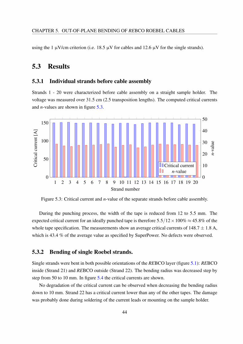
Strands 1 - 20 were characterized before cable assembly on a straight sample holder. Thevoltage was measured over 31.5 cm (2.5 transposition lengths). The computed critical currentsand n-values are shown in figure 5.3.
Figure 5.3: Critical current and n-value of the separate strands before cable assembly.
During the punching process, the width of the tape is reduced from 12 to 5.5 mm. Theexpected critical current for an ideally punched tape is therefore 5.5/12×100%≈ 45.8% of thewhole tape specification. The measurements show an average critical currents of 148.7± 1.8 A,which is 43.4 % of the average value as specified by SuperPower. No defects were observed.
5.3.2 Bending of single Roebel strands.
Single strands were bent in both possible orientations of the REBCO layer (figure 5.1): REBCOinside (Strand 21) and REBCO outside (Strand 22). The bending radius was decreased step bystep from 50 to 10 mm. In figure 5.4 the critical currents are shown.
No degradation of the critical current can be observed when decreasing the bending radiusdown to 10 mm. Strand 22 has a critical current lower than any of the other tapes. The damagewas probably done during soldering of the current leads or mounting on the sample holder.
44
5.3. RESULTS
0 10 20 30 40 500
50
100
150
Bending radius [mm]
Cri
tical
curr
ent[
A]
REBCO inside (strand 21)REBCO outside (strand 22)
Figure 5.4: Critical current of the Roebel strands with decreasing bending radii.
5.3.3 Bending of Roebel cables
The voltage taps were soldered on the strands outside of the current leads (figure 5.5). Thiscould be done only on six of ten strands in each cable, as the remaining four did not stick outof the current lead far enough. Critical currents and were computed for the measured pairs andaverages are shown in the figure 5.6. Three of the strands in cable 2 (6, 8 and 16) showedresistive behavior for an unknown reason and were excluded from the average.
r = 50 mm r = 10 mm
Figure 5.5: A Roebel cable mounted on the sample holder. The voltage taps are the thin coloredwires visible in the left of the picture. They are connected outside of the current leads.
The critical current of cable 1, which had its REBCO layer facing inwards, degraded by63 A (≈ 6%) when the bending radius was decreased from 26 to 20 mm. Cable 2 did not showany degradation during bending to this point. However, the number of data points is insufficientto conclude if this difference is related to the orientation of the tape (REBCO inside/outside).
No degradation was observed when decreasing bending the bending radius further down to10 mm. The critical currents even slightly increased for the lowest bending radii. So far no
45
CHAPTER 5. OUT-OF-PLANE BENDING OF REBCO ROEBEL CABLES
explanation for this behaviour has been found.
0 10 20 30 40 500
200
400
600
800
1,000
Bending radius [mm]
Cri
tical
curr
ent[
A]
REBCO inside (Cable 1)REBCO outside (Cable 2)
Figure 5.6: Critical current of the Roebel cables with decreasing bending radii.
5.3.4 Individual strands after cable disassembly
Since the voltage was measured over the entire cable length, including the soldered contacts,one cannot be sure about the location of any degradation. The cables were disassembled andthe individual strands were measured once more, this time only over 10 cm length including thesegment that was bent.
Figure 5.7: Critical currents of the single Roebel strands before and after bending.
Strand 12 shows a degradation of about 24%. Statistically, however, this strand is an outlier:the average critical current after bending is 147.7± 9.2 A, compared to 148.7 A before cabling.This is an average degradation of less then 1%. It can be concluded that cable bending to 10 mmcauses hardly any degradation of the critical current.
46
5.4. CONCLUSION
5.4 Conclusion
Degradation due to bending strain was low (< 6.5 %) to zero for bending radii in the range 10- 50 mm. To locate the damage, the cables were disassembled and the separate strands weremeasured once more, but this time only in the bent section. These measurements show that theaverage degradation in the bent section was less then 1%.
Based on this results a sample holder with 20 mm bends was constructed for the press atTwente University. The sample holder is discussed in more detail in section 6.2.3.
47
Chapter 6
Transverse strength of a REBCO Roebelcable
6.1 Introduction
In this chapter, the central question of the master assignment is addressed: “Can impregnationreduce the transverse pressure sensitivity of REBCO Roebel cables?” To answer this question,the critical current of a cable was measured at various pressure levels. The experimental detailsare destribed in described in section 6.2, the first results in section 6.3.
6.2 Experimental details
The measurements were done in a unique set-up at Twente University, which comprises a totalof nine superconducting coils. It is capable of currents up to 50 kA, forces up to 250 kNand a background field of 11 T (figure 6.1). The system contains a lot of low-temperaturesuperconducting wires, and it is therefore always operated in a liquid helium bath (T = 4.2 K).The transformer, the press and its geometry and sample preparation are discussed.
49
CHAPTER 6. TRANSVERSE STRENGTH OF A REBCO ROEBEL CABLE
Iprimary
Isecondary
50 kA superconducting transformer
Resistive jointSample (U-shaped)
11 T background magnet
250 kN cryogenic pressF
Figure 6.1: Scheme of the press set-up.
6.2.1 Superconducting transformer
The sample current is supplied by a superconducting transformer, which was built at TwenteUniversity [57, 58]. The transformer consists of a primary coil with a large number of turns,and a secondary coil with just one-and-a-half turns (see figure 6.2). Both coils are wound withNbTi wires. The secondary coil is connected to the sample, while the primary coil is connectedto a current source. The transformer amplifies the current by a factor 1000. In this way, samplecurrents of 50 kA can be reached using only a small and relatively inexpensive 50 A currentsource. Another advantage is that the resistive current leads between the 4.2 K transformer andthe room temperature power supply can be designed with a 1000 times smaller cross-section.This reduces the heat flow into the cryostat and saves liquid helium.
Transformers in resistive circuits can be operated only with alternating currents, since theyrely on an induced voltage. In a superconducting transformer, the situation is different. Thesecondary coil is soldered to the superconducting sample, forming a loop with the solderedjoints as the only resistive parts. Without an induced voltage due to flux coupling with theprimary coil, the current decays exponentially with a time constant τ = L/R, in which L is theself-inductance and R the resistance of the loop. A self-inductance of about 1 µH and a jointresistance of typically 2 nΩ result in a decay time of 500 s. This is a relatively slow decay, andcan be compensated for by slowly increasing the primary current. In this way, the transformercan essentially be operated in DC mode for a limited time.
50
6.2. EXPERIMENTAL DETAILS
Superconducting shield with Hall sensor
Primary coil
Secondary coil
Calibration coil
Rogowski pick-up coil
Correction coil (through Rogowski coil)
Joint between the secondary coil and the sample
Figure 6.2: The superconducting transformer without its steel cover. Picture from W. Wessel[59].
Current meter
Measuring the current in the secondary coil is not straightforward. Adding a shunt resistor inseries with the coil is not an option, as it would severely decrease the decay time and thus limitthe measurement time. Direct magnetic measurements using a Hall sensor would be disruptedby the magnetic field of the many nearby coils. A new and accurate current meter was developedby H. ten Kate et al. specifically for use in these conditions [60, 61].
The electric scheme of the transformer is shown in figure 6.3. The core of the current meteris the purple superconducting loop consisting of the toroidal Rogowski coil and the Hall sensorcoil connected in series. The Rogowski coil encloses the loop carrying the secondary current:the two loops are coupled and act like another transformer. A change in secondary currentinduces a current in the purple loop that does not decay. The loop current is detected by aHall sensor, which is located above the transformer and shielded from all other magnetic fields
51
CHAPTER 6. TRANSVERSE STRENGTH OF A REBCO ROEBEL CABLE
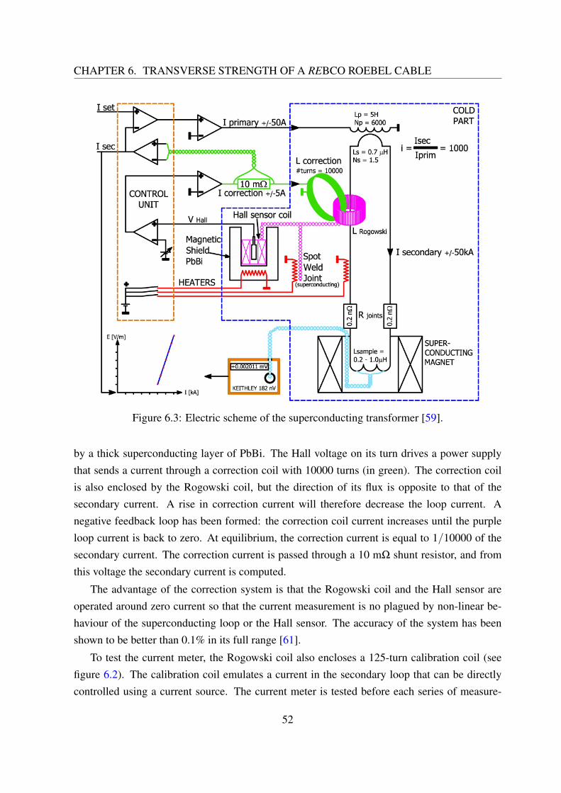
Figure 6.3: Electric scheme of the superconducting transformer [59].
by a thick superconducting layer of PbBi. The Hall voltage on its turn drives a power supplythat sends a current through a correction coil with 10000 turns (in green). The correction coilis also enclosed by the Rogowski coil, but the direction of its flux is opposite to that of thesecondary current. A rise in correction current will therefore decrease the loop current. Anegative feedback loop has been formed: the correction coil current increases until the purpleloop current is back to zero. At equilibrium, the correction current is equal to 1/10000 of thesecondary current. The correction current is passed through a 10 mΩ shunt resistor, and fromthis voltage the secondary current is computed.
The advantage of the correction system is that the Rogowski coil and the Hall sensor areoperated around zero current so that the current measurement is no plagued by non-linear be-haviour of the superconducting loop or the Hall sensor. The accuracy of the system has beenshown to be better than 0.1% in its full range [61].
To test the current meter, the Rogowski coil also encloses a 125-turn calibration coil (seefigure 6.2). The calibration coil emulates a current in the secondary loop that can be directlycontrolled using a current source. The current meter is tested before each series of measure-
52
6.2. EXPERIMENTAL DETAILS
ments.
Feedback loop for the secondary current
Without an induced voltage, the secondary current will decay slowly due to dissipation in thesoldered joints. The control unit of the transformer features a feedback loop that can keepthe secondary current at a certain level. When enabled, the voltage over the correction shuntresistor is subtracted from a certain set voltage (Iset and Isec in figure 6.3). The voltage differencedrives the voltage over the primary coil, ramping it until the secondary current reaches thedesired level. The set voltage can be controlled externally for automatized measurements witha computer.
Heaters and quench protection
There are electric heaters on the secondary coil, on the Rogowski coil loop and on the supercon-ducting shield. These heaters are used to quench the respective parts and remove any current.The heaters can be switched on or off manually using the control unit.
The thermal stability of Roebel cables at T = 4.2 K has not been analysed yet. The cablemight quench and the resulting temperature rise might cause damage. To prevent the cable fromburning, a quench detector was installed that automatically turns on the secondary heater if itsinput voltage exceeds a threshold of about 7 mV. (Basically, the relay output of the quench de-tector was soldered in parallel with the switch in the control unit.) By quenching the secondarycoil, part of the energy stored in the loop is dissipated there, and not in the sample. The tem-perature rise will therefore be smaller. In the experiments carried out for this assignment, thesample did not quench, and the quench protection had not been necessary.
6.2.2 Cryogenic press
The transverse stress on the sample is generated by a superconducting press built at TwenteUniversity [62]. The different parts of the press are shown in figure 6.4. On the bottom thereare two NbTi “pancake” coils. The currents in both coils run in opposite directions, resultingin a repulsive Lorentz force between them up to 250 kN. The lower pancake coil is fixed tothe sample holder by the stainless steel outer structure. The upper pancake coil lifts the innercylinder which pushes against the sample. A pushing block with a sample-specific geometrycan be attached on top of the inner cylinder. For our measurements, the pushing block is notattached here, but glued on the sample (see section 6.2.3). Three springs separate the upper coilfrom the outer structure, to prevent the inner cylinder from being launched at high speed.
53
CHAPTER 6. TRANSVERSE STRENGTH OF A REBCO ROEBEL CABLE
Fixation holes for thesample holder
Outer structure
Inner cylinder
Extensometer tipSpring (3×)Upper pancake coil
Lower pancake coil
Figure 6.4: The disassembled cryogenic press.
The upward force on the inner cylinder is described by the following equation [62]:
F = I2p
∂M12
∂ z± IpIm
∂Mm1
∂ z−mg (6.1)
In this equation,
• Ip is the press current in A• Im is the current of the background magnet in A• M12 is the mutual inductance between the two pancake coils in H• Mm1 is the mutual inductance between the upper pancake coil and the background magnet
in H• m = 11 kg, the mass of the upper pancake coil and the inner cylinder• g = 9.81 m/s2, the gravitational acceleration• z is the vertical dimension
The first term is the repulsive force between the two pancake coils. The second term describesthe force on the upper pancake coil due to the background magnetic field. Its sign dependson the relative direction of the currents in the upper pancake coil and the background magnet.
54
6.2. EXPERIMENTAL DETAILS
During the measurements described in this report, the currents were anti-parallel, leading to arepulsive force. The background field of the main magnet pushed the upper pancake coil downand the force on the sample is decreased. The sign of the second term should therefore benegative. The third term is a correction for the gravitational force on the movable parts.
∂M12/∂ z and ∂Mm1/∂ z can be approximated by a linear expressions depending on the dis-placement of the upper pancake coil ∆z [62]:
∂M12/∂ z≈ a1∆z+b1 (6.2)
∂Mm1/∂ z≈ a2∆z+b2 (6.3)
With coefficients:a1 = −2710 H/m2
b1 = 82.47 H/m
a2 = 23 H/m2
b2 = 2.277 H/m
(6.4)
Extensometer
The derivative of the mutual inductances and thereby the force depend on the displacement ofthe upper coil ∆z. It is therefore necessary to measure this displacement. This is done usingan extensometer (figure 6.5). A cylinder with a sharp tip is fixed on the upper pancake. Thetip pushes against a plate of a titanium-alloy. This plate is fixed to the outer structure of thepress, to which the lower pancake coil is also fixed. Four strain gauges in a Wheatstone bridgeconfiguration are glued onto the plate. The Wheatstone bridge configuration ensures a highsensitivity and a linear response. A current of 1 mA is used to excite the bridge.
The extensometer was calibrated by W. van de Camp [63, p. 76]. A linear calibration factor
Figure 6.5: The extensometer.
55
CHAPTER 6. TRANSVERSE STRENGTH OF A REBCO ROEBEL CABLE
was determined of 1.080 V/m at room temperature and 1.046 V/m at T = 77 K. For measure-ments at T = 4.2 K, the calibration factor 1.046 V/m is used.
6.2.3 Sample holder and pushing block
The background magnet has an inner bore of 8 cm. A U-shaped sample holder is used to attaina horizontal measurement section in the center of the magnet (figure 6.1). The original sampleholder had 10 mm radius bends and a 46 mm straight section in between. This holder was usedto test Nb3Sn cables which were reacted in the required shape, so the low bending radius wasnot a problem. REBCO cables are always made from ready-made tapes, which contain a brittleREBCO layer. The bending properties of the cable therefore need to be taken into account. Inchapter 5, we show that, at 77 K, Roebel cables can be bent down to a 10 mm bending radiuswithout degradation. Still, we chose to use a sample holder with 20 mm bending radius to leavesome margin for additional stresses, which could result from impregnation, further cool-downto 4.2 K or Lorentz forces. The bending radius of one sample holder was increased to 20 mmby spark erosion (see figure 6.6a). The remaining straight section has a length of 26 mm.
The pushing block is shown in figure 6.6b. The face that presses the cable has is 12 mmwide and 30 mm long, corresponding to 24.8% of the transposition length. The pushing block
(a) Sample holders (b) Pushing block
Figure 6.6: (a) An original sample holder with 10 mm bending radius (left) and the modifiedsample holder with 20 mm bending radius (right). (b) The pushing block. The lower side is theside facing the cable.
56
6.2. EXPERIMENTAL DETAILS
is longer than the straight section of the sample holder. This is done to avoid a high local strainat the corners of the pushing block. The two rectangular holes are used to position the pushingblock so that its surface is parallel to the inner cylinder of the press. This ensures that thepressure is evenly applied to the cable. The pushing block is then glued to the sample in thisposition over 30 mm. The sides of the pushing block are covered in Kapton polyimide tape,to prevent unwanted adhesion to the sample holder. The top is also covered in four layers ofKapton tape. The idea is that this soft layer will redistribute the force if the pushing block isstill not properly aligned to the inner cylinder.
For calculation of the stress, a sample length of 30 mm is used, even though the straightsection of of the sample is only 26 mm. As the pushing block is 30 mm long, this correspondsto the largest possible pressed surface, i.e. the minimum average pressure.
A 30 mm sample length is assumed as well of for determining the critical current. Thecritical current of a Roebel cable is strongly dependent on the orientation of the magnetic field(see figure 1.1). A voltage will therefore arise only in the cable section where the angle betweenthe wide surface and the magnetic field is close to 90. As the straight section of the cable isshort compared to the bends, this length is not well-defined. For determining the critical current,a sample length of 30 mm is used, corresponding to the pushing block length. The motivationis that all damage due to pressing will occur in this segment.
More information about the sample holder design can be found in appendix B. Technicaldrawings can be found in appendix C.
6.2.4 Sample description and preparation
The cable was made from SuperPower SCS12050-AP REBCO tape. This tape is 12 mm wide,has a 50 µm thick Hastelloy substrate, 2 µm silver and 40 µm copper stabilization. More
Table 6.1: Conductor specification as supplied by SuperPower. The critical current was mea-sured at T = 77 K and in self-field.
57
CHAPTER 6. TRANSVERSE STRENGTH OF A REBCO ROEBEL CABLE
conductor specifications are listed in table 6.1. A 75 cm long, 10-strands cable was preparedfrom this tape following the procedure in section 2.1.
Next, the cable was mounted on the sample holder. The REBCO side of the cable facedthe sample holder, as this side will be soldered to the transformer. This orientation is usedfor a lower contact resistance, as in opposite orientation the current would be forced to flowthrough the copper edges of the tape or through the highly resistive substrate and buffer layers.At the horizontal segment, the cable is supported against the sideways Lorentz forces by thicksteel plates. In the vertical section, the cable experiences a small outward Lorentz force causedby its own magnetic field. The cable is supported by steel plates against this force too. Allmetal surfaces that can be touched by the cable were covered with Kapton polyimide tape forelectrical insulation. Pairs of voltage taps were soldered on three strands over a distance of onetransposition length (figure 6.7a). A block of Teflon was pushed against the horizontal segmentto create a flat epoxy surface and prevent it from flowing out during the curing process (figure6.7b).
The cable was impregnated using the same procedure that was successfully used on dummycables. This method is described in section 4.4 and appendix A. The impregnation set-up usedat UTwente is very similar to the one used at KIT. The main difference is that the sample holderand resin container are heated using heating resistors instead of an oven. Because the resincontainer is bigger, 280 g of resin needs to be prepared.
Figure 6.7c shows the cable after impregnation. The surface looks flat with the naked eyeand no bubbles are visible in the resin. The big dark stain was already there before impregnation.Next, two layers of glass cloth with Stycast 2850FT/23LV epoxy were added to the cable. Thepushing block was positioned in the epoxy using two spark eroded plates which were fixed tothe sample holder with the 25 mm fixation cylinders. This method makes sure that the pushingblock is properly aligned to the press. The distance between the lower side of the pushing blockand the sample holder is 1.5 mm, leaving an approximately 0.8 mm thick layer of epoxy. Thepositioning plates were removed after the glue had become dry. Figure 6.7d shows the pushingblock glued in place.
Then the sample holder was attached to the transformer. The Roebel cable was solderedbetween the transformer cable and a copper plate over a length of 126 mm with Sn97Ag3 solder.A hot plate was used to heat the cables.
Finally, the sample was fixed to the sample holder. At the current leads, this was done bywrapping it in glass fibre tape with Stycast epoxy. Below the current leads, the cable was fixedwith four pairs of stainless steel plates screwed together, replacing the tie-wraps in figure 6.7b.
58
6.2. EXPERIMENTAL DETAILS
(a) Voltage taps on three strands. (b) Cable prepared for impregnation.
(c) After impregnation. (d) Pushing block glued in place.
(e) Current contact before soldering. (f) After soldering.
Figure 6.7: Preparation of the sample.
59
CHAPTER 6. TRANSVERSE STRENGTH OF A REBCO ROEBEL CABLE
6.3 Results
6.3.1 Critical current of separate strands
Before cable assembly, the separate strands were measured in a liquid nitrogen bath (T = 77 K)and no external magnetic field. The voltage was measured over a distance of 67 cm. The strandshad an average critical current of 173.3± 2.0 A, 43.5% of the specification of the unpunchedtape. For an ideally punched tape this value would be 45.8% (see section 5.3.1). The averagen-value was 29.0±1.0. No defects were found; all strands could be used for cabling.
1 2 3 4 5 6 7 8 9 100
50
100
150
200
Strand number
Cri
tical
curr
ent[
A]
Critical currentn-value
0
10
20
30
40
50
n-va
lue
Figure 6.8: Critical currents and n-values of the separate strands.
6.3.2 Joint resistance
The secondary loop is basically an RL-circuit. Without an induced voltage from the primarycoil, the current decays exponentially with a time constant τ:
I(t) = I0 e−t/τ (6.5)
τ = L/R (6.6)
The self-inductance of the loop is approximately L = 1 µH. The loop resistance R can becomputed from the time constant by observing the current decay when the feedback systemis switched off.
A current of about 1 kA was induced, without external magnetic field and without appliedpressure. The current decay over time is shown in figure 6.9. The current was found to decay
60
6.3. RESULTS
0 20 40 60 80 100 120102
103
104
Time [s]
Cur
rent
[A]
Measured currentτ = 163 s
Figure 6.9: Decay of the sample current due to joint resistance.
exponentially with a decay time of 163 s. The loop resistance is therefore
R = L/τ = 6.13 nΩ (6.7)
or 3.06 nΩ per joint. The joints have an area of 12 mm× 126 mm, thus the surface resistivityis:
3.06 nΩ∗12 mm∗126 mm = 4.63∗10−12Ωm2 (6.8)
This is a slightly lower value than the 8.92∗10−12 Ωm2 reported by J. Fleiter [25].Since the self-inductance value is only an estimate, the computed joint resistance is not
very accurate. The self-inductance for this specific sample geometry must be computed moreaccurately for a better determination of the joint resistance.
6.3.3 Initial pressure loading
Figure 6.10 shows the displacement of the upper pancake coil as a function of the upwardsforce. A force of about 966 N is needed to lift the coil and the cylinder. This is higher than themg = 108 N force due to gravity mentioned in section 6.2.2. An explanation for the differenceis the fact the the force due to the three springs (figure 6.4) is not included in the force equation.From now on, 966 N is taken as a zero point for force on the sample:
F = I2p(a1∆z+b1)− IpIm(a2∆z+b2)−F0 (6.9)
with the coefficients a1,b1,a2 and b2 as in equation 6.4 and F0 = 966 N.
61
CHAPTER 6. TRANSVERSE STRENGTH OF A REBCO ROEBEL CABLE
0 1 2 3 40
0.5
1
1.5
2
Force [kN]
Dis
plac
emen
t[m
m]
Figure 6.10: Displacement of the upper pancake coil at low forces.
6.3.4 Transverse pressure dependence of the critical current
After initial loading, the background magnet was ramped to 10.5 T (Im = 84.4 A). In figure6.11, the first successful IV-measurement is shown. The voltage could be measured over thecurrent leads and over one strand near the horizontal section of the cable. Of the two remainingvoltage pairs, one was used as input for the quench detector, and one did not yield useful data,possibly due to a short circuit. The voltage over the current leads shows a 6.5 nΩ resistive slopesuperimposed on the superconductor characteristic. This is consistent with the result from thecurrent decay (6.3.2) and is hence likely due to the resistive joints. For computing the criticalcurrent, the voltage over the strand is used. As a sample length of 30 mm is assumed, the voltage
0 0.5 1 1.5 2 2.5
0
10
20
Current [kA]
Volta
ge[µ
V]
Current contactsStrand
Figure 6.11: IV-curves made at a pressure of 4.09 MPa. The voltage was measured over thecurrent contacts and over one strand near the horizontal section. The critical current is 2070 A.
62
6.3. RESULTS
criterion is 3 µV.
The initial critical current of the cable was 2.07 kA. For comparison, J. Fleiter measured acritical current of 2.4 kA in a similar cable in a 9.6 T magnetic field [25]. However, Fleiter’scable was made of a different batch of REBCO tapes that had a lower critical current at 77 K.Also, the ratio of the critical current at T = 77 K, B = 0 T and T = 4.2 K, B = 10.5 T may bedifferent for the two cables. This comparison can therefore not be used to verify that our cablewas not damaged by impregnation.
Figure 6.12 shows the critical current as a function of the transverse stress. The transversestress was calculated by dividing the force by the 12 mm× 30 mm sample area. The stresswas increased in steps of about 10 MPa. At 262 MPa, the first degradation was observed, adecrease of about 4%. At 318 MPa, the critical current decreased by a further 21%. After thefirst degradation, each increase in pressure was followed by a measurement at 85 MPa. Noneof the degradation was reversible.
0 50 100 150 200 250 300 3500
0.5
1
1.5
2
2.5
Transverse stress [MPa]
Cri
tical
curr
ent[
kA]
Figure 6.12: The critical current as a function of transverse stress.
The measurements show that the impregnated cable could withstand transverse pressuresup to 253 MPa. This is a significant increase in strength compared to D. Uglietti’s experiments[23], especially in view of the design requirement of approximately 150 MPa for acceleratormagnets.
63
CHAPTER 6. TRANSVERSE STRENGTH OF A REBCO ROEBEL CABLE
6.3.5 Microscopic analysis
In order to verify that also this impregnation went as planned and to check for possible damagedue to the transverse stress, a cross-section of the sample was made for optical inspection. Thecable and the pushing block to which it was still glued were cast in epoxy. Material was removedby sanding until the pressed section reached the surface. The surface was polished and pictureswere made using an optical microscope.
Figure 6.13 shows an overview of the cable cross-section. The impregnation quality of thecable looks good; there are no bubbles visible. In the Stycast layer with which the block wasglued to the cable, there are some holes because no vacuum was used. The thickness of thewhole structure is close 1.45 mm over the entire width. Including the 50 µm Kapton insulation,the distance between the sample holder and pushing block was 1.50 mm, as designed.
Casting epoxy
Stycast with glass fiber
Pushing block
Impregnation epoxy
2 mm
Figure 6.13: Overview of the cross-section. The upper surface was on the sample holder.
Note that the impregnated cable by itself is thicker on the left than on the right, probablybecause the Teflon block was not exactly parallel to the sample holder. The difference in heightis corrected by glueing the pushing block using the positioning plates.
The only visible damage is delamination of the tapes closest to the sample holder. It’s clearlyvisible in figure 6.14. The delamination may have occurred when the cable was removed fromthe sample holder. This was the only step in which a ‘pulling’ force was needed. Since thecross-section was made after many steps (cable assembly, impregnation, cool-down, pressuretest, warming-up and finally removal from the sample holder), we cannot be entirely sure whenthe delamination occurred.
64
6.4. CONCLUSION
Figure 6.14: Close-ups of the left end, the central hole and the right end. Delamination is visiblein the upper right tape.
6.3.6 Discussion
As shown in figure 6.7d, the pushing block is glued to the cable using Stycast epoxy. At thewriting of this report, a remaining point of discussion is the bond between the pushing blockand the stainless steel plates besides the sample. If the block is glued to these plates, a part ofthe force is directly transferred to the sample holder, leading to a lower pressure on the cable. Toavoid a strong bond, both the pushing block and the plates were covered with Kapton polyimidetape. This tape has a silicone adhesive, which has a relatively low lap-shear strength of 1.7-3.4 MPa [64, p. 171]. On both sides of the pushing block, an area of 12 mm×30 mm is facingthe side plates. Assuming that the entire area is glued, the bond could transmit a force of:
2∗12 mm∗30 mm∗3.4 MPa = 2.5 kN (6.10)
This corresponds to a maximum error of 6.8 MPa in the sample pressure, 2.7% compared to its253 MPa strength. In reality, not the entire area was glued, so the error should be lower.
A second discussion point is that the pressed section (30 mm) is shorter than the transposi-tion length (126 mm). In the pressed section, only four out of ten strands have a ‘bridge’ fromone side of the cable to the other, which is where stress concentrations occur. As a result, themeasured degradation would be lower than in the case of a longer pushing block. This shouldhowever not affect the point of onset of the degradation.
6.4 Conclusion
A REBCO Roebel cable was vacuum impregnated with a mixture of epoxy resin and fusedsilica powder. The impregnated cable was tested in a transverse press set-up at T = 4.2 K,B⊥ = 10.5 T. The initial critical current was 2070 A. Pressures up to 327 MPa were applied to a
65
CHAPTER 6. TRANSVERSE STRENGTH OF A REBCO ROEBEL CABLE
30 mm long pushing block, which was glued onto the cable. No degradation was observed forpressures up to 253 MPa. After further loading to 327 MPa, the critical current decreased by21%. The degradation was not reversible.
These results provide a first encouraging indication that suitably impregnated REBCO Roebelcables can indeed withstand the transverse pressure levels occurring inside the winding pack ofa dipole-type accelerator magnet.
66
Chapter 7
Conclusions and recommendations
The aim of this assignment was to find out whether impregnated REBCO Roebel cables canwithstand the transverse stresses up to 150 MPa in an accelerator magnet. Before the stress testcould be done, a suitable impregnation material and method had to be found, and the effect ofout-of-plane bending needed to be determined. A new U-shaped sample holder for the presswas constructed according to the measured bending properties. A REBCO Roebel cable wasimpregnated on this sample holder, and subjected to pressures up to 327 MPa.
In chapter 3 and 4, impregnation materials and techniques were discussed. A mixture ofhigh-temperature processed epoxy and fused silica was found to be suitable for the cable exam-ined in this work. Using vacuum impregnation, a dummy cable was successfully impregnatedwith this material. The critical current of a dummy cable with one superconducting strand wasnot affected by impregnation.
The out-of-plane bending experiments on two Roebel cables were described in chapter 5.Bending to radii as low as 10 mm hardly damaged the cable. Based on these results, a newsample holder for the transverse press was designed with bends of 20 mm radius.
The central question of the assignment was addressed in chapter 6. Here the measurementsof an impregnated Roebel cable in a transverse stress set-up with superconducting transformerwere described. A new technique was used to apply homogeneous transverse loads to sampleswith an inhomogeneous thickness. Transverse stresses up to 253 MPa did not damage the cable.This is a significant improvement compared to previous measurements of bare Roebel cables.Also, it is a first indication that a suitably impregnated Roebel cable can withstand the stresslevels of 150 MPa in a future accelerator magnet.
At the time of writing, this project is still work in progress. One sample has now beenfinished, but at least two more will be measured. The next measurement will be a repetition ofthe first one, but with shorter side plates. This will be done to have more data and to address
67
CHAPTER 7. CONCLUSIONS AND RECOMMENDATIONS
the discussion point described in section 6.3.6. Secondly, a cable with a different lay-out willbe tested; it will consist of nine strands instead of ten. Recent work by J. Fleiter has shown thatthe number of strands influences the effective area of the cable under a transverse load [65].A cable with nine strands was found to have a much smaller effective area than one with tenstrands. With the test of a nine-strand cable we aim to determine whether the effective area canpredict the transverse strength of impregnated cables.
Accelerator magnets need to function for many years, without degrading under their ownLorentz forces. Therefore, the effect of repeated loading on Roebel cables must also be in-vestigated. This is in principle possible in the current set-up, but it would take a lot of timesince the press is manually operated. For such measurements, some automation would be animprovement.
68
Acknowledgements
I would like to thank everybody who made this project possible. In particular I would liketo thank my direct supervisors Marc Dhalle and Anna Kario. I would like to thank WilfriedGoldacker and Marcel ter Brake for giving me the opportunity to work in their groups. I alsothank the technicians Brigitte Runtsch, Andrea Kling, Uwe Walschburger, Bernd Ringsdorf andSander Wessel. Your work was essential for all experiments. Among other things, I thankBrigitte for help with optical microscopy, Andrea for preparation of the cables and the bendingtests, Uwe for construction of the equipment for bending and impregnation, Bernd for the char-acterisation of strands at 77 K and Sander for the modifications to the transformer press set-upand help with operation. The measurements for the characterisation of epoxy resins were per-formed by Nadezda Bagrets and Sandra Drotziger, I thank them for that. Thanks Rainer Nastfor preparation of the samples for the chemical compatibility tests. And thanks Peng Gao for allthe measurements we did together. Finally, I would like to thank Hubert Wilbers from Hunts-man corporation for providing free samples of their epoxy resins and Quarzwerke for supplyingthe fused silica powder.
69
Appendix A
Impregnation procedure
In this appendix the impregnation procedure is described which was used for successful im-pregnation of the sample discussed in section 4.4. The amount of filler is 50 wt% of the totalmixture weight.
Materials:
• 30 cm Roebel dummy• 2×5 cm of stainless steel tape with 12 mm × 0.1 mm cross-section• 30 g Araldite CY5538 (resin)• 30 g Araldur HY5571 (hardener)• 60 g fused silica powder Silbond FW600 EST (4 µm median particle size)• Copper wire and Kapton tape to fix the sample• Vacuum equipment: pump, valve, tubes and pressure gauge• Vacuum mixing set-up: flask with thermocouple and connection to a vacuum pump,
heater with magnetic stirrer (figure A.1a)• Spoon, cups, scale, ethanol, acetone, ultrasonic cleaner, paper towels etc.
Method:
• Set the “vacuum oven” to 105 C, aim for 80 - 90 C inside the vacuum chamber• Set the chemical dryer to 100 C• Clean the sample and the steel tapes in acetone in the ultrasonic cleaner for 15 minutes• Put the sample on the sample holder between the two steel tapes, lay the thick Teflon
sheet on top of it• Force the lower section of the sample into a straight shape with copper wire (figure A.1c)
71
APPENDIX A. IMPREGNATION PROCEDURE
• Fix the rest of the sample to the sample holder with Kapton adhesive tape• Attach the sample holder to the flange and insert it in the vacuum oven (also heat the resin
container)
• Mix the resin, hardener and silica powder in a beaker and heat to 40 - 60 C. It is theeasiest to add the powder in small portions and mix it before adding the next one.• Pour the contents in the vacuum flask, connect the vacuum pump and the thermocouple• Evacuate to 30 mbar, turn on the magnetic stirrer and heat again to 60 C• When the foam has gone down, lower the pressure slowly to 1 - 2 mbar (just above the
vapour pressure)• Mix for about 30 minutes, until only a few gas bubbles are visible• Remove the vacuum, and pour the mixture into the beaker• Heat the mixture to 80 C• Remove the sample holder and resin container from the vacuum oven• Add 20 ml of resin to the brass container with a syringe (resulting in ∼15 mm liquid
level)• Move the container into position for insertion (red line on the rod, then the distance from
flange to the bottom of the container is 40 cm)• Insert the set-up into the vacuum chamber and evacuate to 5 mbar
• Wait at least 5 minutes to degas the resin for the second time, wait some more if thetemperature has not reached 80 C• Slowly raise the resin container until the sample hits the bottom (in ∼1 minute)• Wait for 20 minutes• Remove the vacuum and wait 20 minutes• Remove the sample holder from the vacuum chamber• Wait until the temperature has dropped to < 60 C• Remove the sample slowly from the resin container,• Add Teflon pieces on both sides to prevent the resin from falling out. You can stick them
behind the copper wires used to straighten the cable (figure A.1d).• Impregnation is finished: put excess resin in a cup• Clean up the mess with ethanol/acetone/soap and paper towels. The flask and the resin
container are best cleaned with acetone in the ultrasonic bath.• Cure 24h/100C in the chemical dryer
For the first few samples a curing temperature of 130 C was used. This led to bucklingof a tape in a sample not described in this report. After correspondence with Huntsman it was
72
(a) Vacuum flask with magnetic stirrer and ther-mocouple
(b) Fully fixed sample
(c) Pressure is applied using piece of Teflon andcopper wire
(d) Pieces of Teflon to prevent epoxy leaking out
Figure A.1
73
APPENDIX A. IMPREGNATION PROCEDURE
decided to use a lower curing temperature of 100 C, to reduce thermal stresses after cool-down.
74
Appendix B
Press design
Note: The following appendix was written in an early stage of the project. It is therefore not
totally up-to-date: for example, the use of glass fibre is still assumed. After measurements of
the minimum bending radius of Roebel cables, it was found that a press geometry with a flat
anvil should not pose problems. After that, the calculations done in this section were not very
useful anymore, and I decided not to update them.
The original sample holder is not suitable for Roebel cables, as its bending radius of 10mm is too low. The minimum bending radius for SuperPower REBCO tapes is 11 mm [66].At the start of this project is was forseen that for Roebel cables this value would be somewhatlarger because the strands are already subjected to some torsion strain due to cable assembly. Asshown in chapter 5, these expectations were overly pessimistic, which measured cables showingno significant degradation down to bending radii of 10 mm.
Several new designs with larger bending radii were considered (see table B.1 and figureB.1). Designs 1, 2 and 3 have a shorter straight section to increase the bending radius; 4, 5, 6and 7 have no straight section at all and need a cylindrically shaped anvil. All designs have atotal sample holder width of 66 mm, and the thickness of the sample is assumed to be 1.5 mm.The cable geometry is periodic over 12.6 mm. All anvils press over a whole number times thislength.
Sample holders without straight section allow for a large bending radius, but they have someother problems:
• The perpendicular magnetic field component is not homogeneous over the pushing length,which means that the critical current is also not homogeneous over this section.
• The force is not perpendicular to the cable surface everywhere. This will lead to shearstress additional to transverse compressive stress. Shear stresses are undesirable because
Table B.1: Parameters for the seven new press designs.
Anvil length
Pushing length
Straight section
Bending radius
Original
4.
1. 2. 3.
5. 6. 7.
Maximum angle
Figure B.1: Sketches of the different press designs. The 1.5 mm thick sample is in purple.
76
we want to assess the effect of pure transverse pressure. The shear stresses are computedusing Comsol.
• The outside of the curved cable will have a slightly larger bending radius than the inside.This means that, in order to make a good fit, the anvil needs to have a slightly larger bend-ing radius than the sample holder. This radius depends on the thickness of the sample, soonce the anvil is made it can be used for only one specific thickness. If there is no goodfit, the pressure will be concentrated in the center or at the ends of the anvil.
All these effects can be reduced by using a shorter anvil, decreasing the maximum anglebetween the surface of the cable and the force and magnetic field (e.g. design 7). However thiswill lead to a shorter section subjected to pressure.
A flat anvil seems much preferable. If we can prove that 19.9 mm bending radius does notdestroy the cable, we can use design 2.
Comsol calculations on round-anvil designs
Geometries 4 to 7 were inserted into a 2D Comsol model. For the sample holder and the anvil,the material properties of stainless steel 304 at 4 K were used. Our cables will probably consistlargely of fiber glass and epoxy resin, so I used the properties of G10 fiber glass epoxy for thesample.
Material Density [kg m−3] Young’s modulus [GPa] Poisson’s ratio
Table B.2: Relevant material properties from Ekin [67]
More details about the simulation:
• The linear elastic model is used from the structural mechanics module.
• A free triangular mesh is used with the element size set to “extremely fine” near thepressing surface and “finer” everywhere else.
1This value is not from Ekin but it is an educated guess. Because of the anisotropic nature of fiberglass-epoxy,the Poisson’s ratio is actually dependent on the angle relative to the glass fibers. It ranges from 0.06 to 0.32 atroom temperature, for T = 4 K I could not find any value.
77
APPENDIX B. PRESS DESIGN
• A stationary solver is used.
• The top of the sample holder has a fixed position. A pressure of 100 MPa is applied tothe lower surface of the anvil part.
Comsol evaluates the Cauchy stress tensor σσσ in the entire geometry. The normal stress σσσnnn
at the outer surface of the sample is computed by taking the dot product with the normal unitvector nnn.
σσσnnn = σσσ ·nnn =
[σxx σxy
σxy σyy
][nx
ny
]=
[nxσxx +nyσxy
nxσxy +nyσyy
](B.1)
The magnitude of the normal stress is:
|σn|=√(nxσxx +nyσxy)
2 +(nxσxy +nyσyy)2 (B.2)
The shear stress τττ is the stress parallel to the surface, so normal to the normal vector:
τττ =
[σxx σxy
σxy σyy
][ny
−nx
]=
[nyσxx−nxσxy
nyσxy−nxσyy
](B.3)
The magnitude of the shear stress is:
|τ|=√(nyσxx−nxσxy)
2 +(nyσxy−nyσyy)2 (B.4)
The computed normal and shear stresses for the different geometries are shown in figureB.2. The normal stress is close to the expected 100 MPa in the middle of the anvil, especiallyfor the wider designs 4 and 5.
Both the shear stress and normal stress are the highest at the edges of the anvil, becauseof high local deformation. This effect is probably weaker in reality, because the edges are not“infinitely sharp” as in this model. Anyway, it makes sense to round the edges of the anvilslightly before using it.
The computed shear stress may be exaggerated in this model because the sample cannotmove with respect to the sample holder and the anvil. It is as if the sample is glued betweenboth parts. In reality the sample is not fixed to the anvil, and this will relieve part of the shearstress.
78
Figure B.2: Normal and shear stresses at the interface of the sample and the anvil for the differ-ent cylindrically shaped anvils, calculated using Comsol. The applied pressure is 100 MPa.
79
Appendix C
Technical drawings
81
66 R20
+ 0.1
00
20
20 20
15
66
22.
5
20 24
2
2
Deze 3 afmetingen graag controleren
Modified holder (1X)
original_holderWEIGHT:
Stainless steel 316LA4
SHEET 1 OF 5SCALE:1:2
DWG NO.
TITLE:
REVISIONDO NOT SCALE DRAWING
MATERIAL:
DATESIGNATURENAME
DEBUR AND BREAK SHARP EDGES
FINISH:UNLESS OTHERWISE SPECIFIED:DIMENSIONS ARE IN MILLIMETERSSURFACE FINISH:TOLERANCES: LINEAR: ANGULAR:
Q.A
MFG
APPV'D
CHK'D
DRAWN
28
R20.1 +
0.50
36
36
8
15
15
13
13
14.1
A
A
5.75
72
2 -00.1
90°
8
4.
5
SECTION A-A
Clamp plate (2X)
original_holderWEIGHT:
Stainless steel 316LA4
SHEET 2 OF 5SCALE:1:1
DWG NO.
TITLE:
REVISIONDO NOT SCALE DRAWING
MATERIAL:
DATESIGNATURENAME
DEBUR AND BREAK SHARP EDGES
FINISH:UNLESS OTHERWISE SPECIFIED:DIMENSIONS ARE IN MILLIMETERSSURFACE FINISH:TOLERANCES: LINEAR: ANGULAR:
Q.A
MFG
APPV'D
CHK'D
DRAWN
30
6 6
23
7
R0.3 (8X)
Mag ook kleiner
R0.5 (4
X)
15
5 + 0.
020
6 6
Litteken liefst aan deze zijde
Litteken hier
0.01 A
A
12
Litteken hier
0.01 A
Pushing block (1X)
original_holderWEIGHT:
Stainless steel 316LA4
SHEET 3 OF 5SCALE:2:1
DWG NO.
TITLE:
REVISIONDO NOT SCALE DRAWING
MATERIAL:
DATESIGNATURENAME
DEBUR AND BREAK SHARP EDGES
FINISH:UNLESS OTHERWISE SPECIFIED:DIMENSIONS ARE IN MILLIMETERSSURFACE FINISH:TOLERANCES: LINEAR: ANGULAR:
Q.A
MFG
APPV'D
CHK'D
DRAWN
5 ±
1
45 ±0.01 52.5 8.5 21
25
.01
25.00
25
.01
25.00
6.6
R5 6
6
5.025.00
R0.3 (8X)
Mag ook kleiner
150
45
22.
5 6
6
2
2.5
Litteken mag rondom.Litteken hier, geldt ook voor het andere gat.
0.01 B
B
Beide plaatjes moeten gelijk zijn. Liefst dus in dezelfde opspanning maken.
Positioning plate (2X)
original_holderWEIGHT:
Stainless steelA4
SHEET 4 OF 5SCALE:1:1
DWG NO.
TITLE:
REVISIONDO NOT SCALE DRAWING
MATERIAL:
DATESIGNATURENAME
DEBUR AND BREAK SHARP EDGES
FINISH:UNLESS OTHERWISE SPECIFIED:DIMENSIONS ARE IN MILLIMETERSSURFACE FINISH:TOLERANCES: LINEAR: ANGULAR:
Q.A
MFG
APPV'D
CHK'D
DRAWN
D
D
cable
E
SECTION D-D
DETAIL E SCALE 1 : 1
cable
F
F
G
SECTION F-F DETAIL G SCALE 1 : 1
Without pushing block
With pushing block and positioning plates
Assembly
original_holderWEIGHT:
A4
SHEET 5 OF 5SCALE:1:5
DWG NO.
TITLE:
REVISIONDO NOT SCALE DRAWING
MATERIAL:
DATESIGNATURENAME
DEBUR AND BREAK SHARP EDGES
FINISH:UNLESS OTHERWISE SPECIFIED:DIMENSIONS ARE IN MILLIMETERSSURFACE FINISH:TOLERANCES: LINEAR: ANGULAR:
Q.A
MFG
APPV'D
CHK'D
DRAWN
28 M4
R20.1 + 0.50
R1
36
36 1
5 1
5
13
13
14.1
8
A
A
72
2 -00.1
5.75
M4
SECTION A-A
Clamp plate met schroefdraad (3x)
clamp_plate_met_schroefdraad
WEIGHT:
A4
SHEET 1 OF 1SCALE:1:1
DWG NO.
TITLE:
REVISIONDO NOT SCALE DRAWING
MATERIAL:
DATESIGNATURENAME
DEBUR AND BREAK SHARP EDGES
FINISH:UNLESS OTHERWISE SPECIFIED:DIMENSIONS ARE IN MILLIMETERSSURFACE FINISH:TOLERANCES: LINEAR: ANGULAR:
Q.A
MFG
APPV'D
CHK'D
DRAWN
Stainless steel 316L
30
6 6
23
7
R0.3 (8X)
Mag ook kleiner
R0.5 (4
X)
15
5 + 0.
020
6 6 Litteken liefst aan deze zijde
Litteken hier
Litteken hier
0.01 A
0.01 A
A
12
M3
6
15
BB
4
6.5
15
SECTION B-B
Pushing block met schroefdraad (3X)
pushing_block_met_schroefdraad
WEIGHT:
Stainless steel 316LA4
SHEET 1 OF 1SCALE:2:1
DWG NO.
TITLE:
REVISIONDO NOT SCALE DRAWING
MATERIAL:
DATESIGNATURENAME
DEBUR AND BREAK SHARP EDGES
FINISH:UNLESS OTHERWISE SPECIFIED:DIMENSIONS ARE IN MILLIMETERSSURFACE FINISH:TOLERANCES: LINEAR: ANGULAR:
Q.A
MFG
APPV'D
CHK'D
DRAWN
Bibliography
[1] H. ten Kate. Large Hadron Collider and ATLAS: Superconductors for High Energy Physics.Lecture slides for the course Applications of Superconductivity at Twente University.2013.
[2] P. Lee. The expanded ASC “Plots” page. 2014. URL: http://fs.magnet.fsu.edu/
~lee/plot/plot.htm.
[3] L. Bottura, G. de Rijk, L. Rossi, and E. Todesco. “Advanced Accelerator Magnets forUpgrading the LHC”. In: Applied Superconductivity, IEEE Transactions on 22.3 (2012),p. 4002008. DOI: 10.1109/TASC.2012.2186109.
[4] A. Ball et al. Future Circular Collider Study: Hadron Collider Parameters. SpecificationFCC-1401101315-DSC. CERN, 2014.
[5] CERN. EuCARD-2: Enhanced European Coordination for Accelerator Research & De-
[6] M. K. Wu et al. “Superconductivity at 93 K in a new mixed-phase Y-Ba-Cu-O compoundsystem at ambient pressure”. In: Phys. Rev. Lett. 58 (9 1987), pp. 908–910. DOI: 10.1103/PhysRevLett.58.908.
[7] D. Dimos, P. Chaudhari, J. Mannhart, and F. K. LeGoues. “Orientation Dependence ofGrain-Boundary Critical Currents in YBa2Cu3O7−δ Bicrystals”. In: Phys. Rev. Lett. 61(2 1988), pp. 219–222. DOI: 10.1103/PhysRevLett.61.219.
[8] Y. Iijima et al. “Structural and transport properties of biaxially aligned YBa2Cu3O7−x
films on polycrystalline Ni-based alloy with ion-beam-modified buffer layers”. In: Jour-
nal of Applied Physics 74.3 (1993), pp. 1905–1911. DOI: 10.1063/1.354801.
[9] SuperPower Inc. 2G HTS Wire. URL: http://www.superpower-inc.com/content/2g-hts-wire.
[10] X. Xiong et al. “Progress in High Throughput Processing of Long-Length, High Quality,and Low Cost IBAD MgO Buffer Tapes at SuperPower”. In: Applied Superconductiv-
ity, IEEE Transactions on 19.3 (2009), pp. 3319–3322. DOI: 10.1109/TASC.2009.2018816.
[11] H. ten Kate. Pratical superconductors. Lecture slides for the course Applications of Su-perconductivity at Twente University. 2013.
[12] M. Takayasu, F. Mangiarotti, L. Chiesa, L. Bromberg, and J. Minervini. “ConductorCharacterization of YBCO Twisted Stacked-Tape Cables”. In: Applied Superconduc-
tivity, IEEE Transactions on 23.3 (2013), p. 4800104. DOI: 10.1109/TASC.2012.2234182.
[13] D. C. van der Laan. “Development of HTS Conductor on Round Core (CORC) cablesfor fusion applications at Advanced Conductor Technologies”. In: 1st Workshop on Ac-
celerator Magnets in HTS, 21-23 May 2014, DESY (2014).
[14] D. C. van der Laan, P. D. Noyes, G. E. Miller, H. W. Weijers, and G. P. Willering. “Char-acterization of a high-temperature superconducting conductor on round core cables inmagnetic fields up to 20 T”. In: Superconductor Science and Technology 26.4 (2013),p. 045005. DOI: 10.1088/0953-2048/26/4/045005.
[15] W. Goldacker et al. “Roebel cables from REBCO coated conductors: a one-century-oldconcept for the superconductivity of the future”. In: Superconductor Science and Tech-
nology 27.9 (2014), p. 093001. DOI: 10.1088/0953-2048/27/9/093001.
[16] N. J. Long et al. “Development of YBCO Roebel cables for high current transport and lowAC loss applications”. In: Journal of Physics: Conference Series 234.2 (2010), p. 022021.DOI: 10.1088/1742-6596/234/2/022021.
[17] G. Kirby et al. “Accelerator Quality HTS Dipole Magnet Demonstrator Designs for theEuCARD-2, 5 Tesla 40 mm Clear Aperture Magnet (unpublished)”. In: Applied Super-
conductivity Conference 2014, Charlotte (2014).
[18] J. van Nugteren et al. “Study of a 5 T Research Dipole Insert-Magnet using an AnisotropicReBCO Roebel Cable (unpublished)”. In: Applied Superconductivity Conference 2014,
Charlotte (2014).
[19] J. Ekin et al. “Transverse stress and fatigue effects in Y-Ba-Cu-O coated IBAD tapes”.In: Applied Superconductivity, IEEE Transactions on 11.1 (2001), pp. 3389–3392. DOI:10.1109/77.919790.
[20] N. Cheggour et al. “Transverse compressive stress effect in Y-Ba-Cu-O coatings on biaxi-ally textured Ni and Ni-W substrates”. In: Applied Superconductivity, IEEE Transactions
on 13.2 (2003), pp. 3530–3533. DOI: 10.1109/TASC.2003.812390.
[21] N. Cheggour, J. Ekin, C. Thieme, and Y. Xie. “Effect of Fatigue Under Transverse Com-pressive Stress on Slit Y-Ba-Cu-O Coated Conductors”. In: Applied Superconductivity,
IEEE Transactions on 17.2 (2007), pp. 3063–3066. DOI: 10.1109/TASC.2007.897918.
[22] T. Takao et al. “Characteristics of Compressive Strain and Superconducting Property inYBCO Coated Conductor”. In: Applied Superconductivity, IEEE Transactions on 17.2(2007), pp. 3517–3519. DOI: 10.1109/TASC.2007.899654.
[23] D Uglietti, R Wesche, and P Bruzzone. “Effect of transverse load on the critical currentof a coated conductor Roebel cable”. In: Superconductor Science and Technology 26.7(2013), p. 074002. DOI: 10.1088/0953-2048/26/7/074002.
[24] L. Chiesa, N. Allen, and M. Takayasu. “Electromechanical Investigation of 2G HTSTwisted Stacked-Tape Cable Conductors”. In: Applied Superconductivity, IEEE Trans-
actions on 24.3 (2014), pp. 1–5. DOI: 10.1109/TASC.2013.2284854.
[25] J Fleiter, A Ballarino, L Bottura, and P Tixador. “Electrical characterization of REBCORoebel cables”. In: Superconductor Science and Technology 26.6 (2013), p. 065014. DOI:10.1088/0953-2048/26/6/065014.
[26] W. Goldacker et al. “Status of high transport current ROEBEL assembled coated con-ductor cables”. In: Superconductor Science and Technology 22.3 (2009), p. 034003. DOI:10.1088/0953-2048/22/3/034003.
[27] T. Takematsu et al. “Degradation of the performance of a YBCO-coated conductor doublepancake coil due to epoxy impregnation”. In: Physica C: Superconductivity 470.1718(2010), pp. 674 –677. DOI: 10.1016/j.physc.2010.06.009.
[28] C. Barth, N. Bagrets, K. P. Weiss, C. M. Bayer, and T. Bast. “Degradation free epoxyimpregnation of REBCO coils and cables”. In: Superconductor Science and Technology
26.5 (2013), p. 055007. DOI: 10.1088/0953-2048/26/5/055007.
[29] D. C. van der Laan, J. W. Ekin, C. C. Clickner, and T. C. Stauffer. “Delamination strengthof YBCO coated conductors under transverse tensile stress”. In: Superconductor Science
and Technology 20.8 (2007), p. 765. DOI: 10.1088/0953-2048/20/8/007.
[30] Y. Yanagisawa et al. “Remarkable weakness against cleavage stress for YBCO-coatedconductors and its effect on the YBCO coil performance”. In: Physica C: Superconduc-
tivity 471.1516 (2011), pp. 480 –485. DOI: 10.1016/j.physc.2011.05.003.
[31] W. Markiewicz et al. “Design of a Superconducting 32 T Magnet With REBCO HighField Coils”. In: Applied Superconductivity, IEEE Transactions on 22.3 (2012), pp. 4300704–4300704. DOI: 10.1109/TASC.2011.2174952.
[32] H. Park et al. “Mechanical and electric characteristics of vacuum impregnated no-insulationHTS coil”. In: Physica C: Superconductivity (in press) (2014). DOI: 10.1016/j.physc.2014.04.010.
[33] S. Matsumoto et al. “Generation of 24 T at 4.2 K using a layer-wound GdBCO insert coilwith Nb3Sn and NbTi external magnetic field coils”. In: Superconductor Science and
Technology 25.2 (2012), p. 025017. DOI: 10.1088/0953-2048/25/2/025017.
[34] K. Mizuno, M. Ogata, and K. Nagashima. “An Innovative Superconducting Coil Fabrica-tion Method with YBCO Coated Conductors”. In: Quarterly Report of RTRI 54.1 (2013),pp. 46–51. DOI: 10.2219/rtriqr.54.46.
[35] U. P. Trociewitz et al. “35.4T field generated using a layer-wound superconducting coilmade of (RE)Ba2Cu3O7x (RE = rare earth) coated conductor”. In: Applied Physics Letters
99.20, 202506 (2011), p. 202506. DOI: 10.1063/1.3662963.
[36] Y. Yanagisawa et al. “Removal of degradation of the performance of an epoxy impreg-nated YBCO-coated conductor double pancake coil by using a polyimide-electrodepositedYBCO-coated conductor”. In: Physica C: Superconductivity 476.0 (2012), pp. 19 –22.DOI: 10.1016/j.physc.2012.01.025.
[37] G. Schwarz. “Thermal expansion of polymers from 4.2 K to room temperature”. In: Cryo-
genics 28.4 (1988), pp. 248 –254. DOI: 10.1016/0011-2275(88)90009-4.
[38] D. Chichili, J. Hoffman, and A. Zlobin. “Investigation of alternative materials for im-pregnation of Nb3Sn magnets”. In: Applied Superconductivity, IEEE Transactions on
13.2 (2003), pp. 1792–1795. DOI: 10.1109/TASC.2003.812892.
[39] J Sandler et al. “Development of a dispersion process for carbon nanotubes in an epoxymatrix and the resulting electrical properties”. In: Polymer 40.21 (1999), pp. 5967 –5971.DOI: 10.1016/S0032-3861(99)00166-4.
[40] M. J. Biercuk et al. “Carbon nanotube composites for thermal management”. In: Applied
Physics Letters 80.15 (2002), pp. 2767–2769. DOI: 10.1063/1.1469696.
[41] J. N. Coleman, U. Khan, W. J. Blau, and Y. K. Gunko. “Small but strong: A review of themechanical properties of carbon nanotube-polymer composites”. In: Carbon 44.9 (2006),pp. 1624 –1652. DOI: 10.1016/j.carbon.2006.02.038.
[42] C. Wong and R. Bollampally. “Comparative study of thermally conductive fillers for usein liquid encapsulants for electronic packaging”. In: Advanced Packaging, IEEE Trans-
actions on 22.1 (1999), pp. 54–59. DOI: 10.1109/6040.746543.
[43] N. Bagrets, E. Weiss, S. Westenfelder, and K.-P. Weiss. “Cryogenic Test Facility CryoMaK”.In: Applied Superconductivity, IEEE Transactions on 22.3 (2012), pp. 9501204–9501204.DOI: 10.1109/TASC.2011.2176902.
[46] The Engineering Toolbox. Coefficients of Linear Thermal Expansion. URL: http://www.engineeringtoolbox.com/linear-expansion-coefficients-d_95.html.
[48] N. Bagrets, W. Goldacker, S. I. Schlachter, C. Barth, and K.-P. Weiss. “Thermal proper-ties of 2G coated conductor cable materials”. In: Cryogenics 61.0 (2014), pp. 8 –14. DOI:10.1016/j.cryogenics.2014.01.015.
[49] C. Barth. “High Temperature Superconductor Cable Concepts for Fusion Magnets”. PhDThesis. Karlsruhe Institute of Technology, 2013. DOI: 10.5445/KSP/1000035747.
[50] F. de Araujo and H. Rosenberg. “The thermal conductivity of epoxy-resin/metal-powdercomposite materials from 1.7 to 300 K”. In: Journal of Physics D: Applied Physics 9.4(1976), p. 665. DOI: 10.1088/0022-3727/9/4/017.
[51] C. Tsai, H. Weinstock, and W. Overton Jr. “Low temperature thermal conductivity ofstycast 2850FT”. In: Cryogenics 18.9 (1978), pp. 562 –563. DOI: 10 . 1016 / 0011 -2275(78)90162-5.
[52] G. Willering, A. P. Verweij, J. Kaugerts, and H. ten Kate. “Stability of Nb-Ti RutherfordCables Exhibiting Different Contact Resistances”. In: Applied Superconductivity, IEEE
Transactions on 18.2 (2008), pp. 1263–1266. DOI: 10.1109/TASC.2008.920560.
[53] W. M. De Rapper, L.-R. Oberli, B. Bordini, E. Takala, and H. ten Kate. “Critical Currentand Stability of High-Jc Nb3Sn Rutherford Cables for Accelerator Magnets”. In: Applied
Superconductivity, IEEE Transactions on 21.3 (2011), pp. 2359–2362. DOI: 10.1109/TASC.2010.2103549.
[54] C. Schmidt, A. Frank, W. Goldacker, A. Kling, and S. Terzieva. “Progress in assemblingcoated conductor cables by the Roebel technique (RACC)”. In: Physica C: Superconduc-
tivity 469.1520 (2009). Proceedings of the 21st International Symposium on Supercon-ductivity (ISS 2008), pp. 1422 –1426. DOI: 10.1016/j.physc.2009.05.050.
[55] X. Jin et al. “Study on the Mechanism of Preventing Degradation in the Performance ofREBCO Coils”. In: Applied Superconductivity, IEEE Transactions on 24.3 (2014), pp. 1–4. DOI: 10.1109/TASC.2013.2280714.
[56] W. Goldacker et al. “ROEBEL Assembled Coated Conductors (RACC): Preparation,Properties and Progress”. In: Applied Superconductivity, IEEE Transactions on 17.2 (2007),pp. 3398–3401. DOI: 10.1109/TASC.2007.899417.
[57] H. ten Kate, B. ten Haken, S. Wessel, J. Eikelboom, and E. Hornsveld. “Critical CurrentMeasurements of Prototype Cables for the CERN LHC up to 50 kA and between 7 and 13Tesla Using a Superconducting Transformer Circuit”. In: 11th International Conference
on Magnet Technology (MT-11). Springer Netherlands, 1990, pp. 60–65. DOI: 10.1007/978-94-009-0769-0_9.
[58] G. Mulder, H. ten Kate, H. Krooshoop, and L. van de Klundert. “On the Inductive Methodfor Maximum Current Testing of Superconducting Cables”. In: 11th International Con-
ference on Magnet Technology (MT-11). Springer Netherlands, 1990, pp. 479–484. DOI:10.1007/978-94-009-0769-0_82.
[59] W. Wessel. Superconducting transformer for direct currents up to 50 kA. Internal presen-tation at Twente University. 2011.
[60] H. ten Kate, W. Nederpelt, P. Juffermans, F. van Overbeeke, and L. van de Klundert. “ANew Type of Superconducting Direct Current Meter for 25 kA”. In: Advances in Cryo-
[61] H. Weijers, A. Godeke, B. ten Haken, S. Wessel, and H. ten Kate. “Improved Supercon-ducting Direct Current Meter for 25-50 kA”. In: Advances in Cryogenic Engineering.Vol. 39. Advances in Cryogenic Engineering. Springer US, 1994, pp. 1147–1152. DOI:10.1007/978-1-4615-2522-6_140.
[62] H. Boschman, A. Verweij, S. Wessel, H. ten Kate, and L. J. M. Van de Klundert. “Theeffect of transverse loads up to 300 MPa on the critical currents of Nb3Sn cables [forLHC]”. In: Magnetics, IEEE Transactions on 27.2 (1991), pp. 1831–1834. DOI: 10.1109/20.133551.
[63] W. van de Camp. “Critical current versus transverse stress and thermal stability of a RRPNb3Sn Rutherford cable”. Master thesis. Twente University, 2012.
[64] S. Ebnesajjad. “Characteristics of Adhesive Materials”. In: Handbook of Adhesives and
Surface Preparation. Ed. by S. Ebnesajjad. Plastics Design Library. Oxford: WilliamAndrew Publishing, 2011, pp. 137 –183. DOI: 10.1016/B978- 1- 4377- 4461- 3.10008-2.
[65] J. Fleiter, A. Ballarino, W. Goldacker, and A. Kario. “Characterization of Roebel Cablesfor Potential use in High-Field Magnets (unpublished)”. In: Applied Superconductivity
Conference 2014, Charlotte (2014).
[66] D. W. Hazelton, Y. Y. Xie, Y. Qiao, E. Zhang, and V. Selvamanickam. “SuperPowersSecond Generation HTS Conductor Design for Stability and Low AC Losses”. In: AIP
Conference Proceedings 824.1 (2006), pp. 859–868. DOI: 10.1063/1.2192434.
[67] J. Ekin. Experimental Techniques for Low-Temperature Measurements: Cryostat Design,
Material Properties and Superconductor Critical-Current Testing. OUP Oxford, 2006.