ASCE Earth and Space 2012 Conference Traverse Planning Experiments for Future Planetary Surface Exploration Pasadena, California April 18, 2012 https://ntrs.nasa.gov/search.jsp?R=20120008542 2018-07-07T12:02:38+00:00Z
Traverse Planning Experiments for Future Planetary Surface Exploration
Purpose of Investigation
Evaluate methodology and data requirements for remotely-assisted robotic traverse of extraterrestrial planetary surface to support human exploration program, assess opportunities for in-transit science operations, and validate landing site survey and selection techniques during planetary surface exploration mission analog demonstration at Haughton Crater on Devon Island, Nunavut, Canada
• Identify quality of remote observation data sets (i.e., surface imagery from orbit) required for effective pre-traverse route planning. Determine ifsurface level data (i.e., onboard robotic imagery or other sensor data) is required for a successful traverse, and if additional surface level data can improve traverse efficiency or probability of success. (TRPF Experiment)
• Evaluate feasibility and techniques for conducting opportunistic science investigations during this type of traverse. (OSP Experiment)
• Assess utility of remotely-assisted robotic vehicle for landing site validation survey. (LSV Experiment)
1
This presentation will focus on the first of these investigations.
A report of activities completed in 2010 can be found in NASA TM-2011-216157
The traverse investigation was continued in 2011. Preliminary results will be discussed.
Page 3
• White Arrows= Traverses• Single Arrow= Lead and Trail Traverse• Double Arrows= Divide and Conquer Traverse• Yellow Dashed Arrow= Traverse to Landing Site• Yellow star indicates landing site• Red dashed line is “Follow the Light” Traverse• Black dashed line = un-crewed traverse from Shackleton to Malapert
• K) Days 8-9 Traverse ~60km to ridge, explore base • L) Day 10 Divide and Conquer Exploer “Blue Crater” and rim of “Old Crater”(~40 km)
• M) Day 11 Explore “Green Crater”/ meet up that night (~25 km)
• N) Day 12- 14 Traverse to Landing site (~130 km)
• P) Day 17 Divide and Conquer West Explore “Too Blue Crater” (~25 km)
• Q) Day 18 Divide and Conquer West Explore “Twins Crater” (one rover North the other South ~30 km)
K MMN
Q
• R) Day 19 Divide and Conquer further West Explore “Twins Crater” and Cabeus (~10 km)
R
• S) Day 20 Traverse to and explore “Maroon Crater”(~65 km)
• T) Day 21-23 Traverse to Landing Site coming up the Southern Ridge of Malapert (~ 40 km uphill)
S T
• U) Day 24-27 Contingency/ Hi-grade/ package/ ascent prep
• V) Day 28 Ascent
U/V
~20 km
• O) Day 15-16 Landing site ops/ hi-grade/ sort/ maint.
O
Hayworth Crater
• ATHLETE, LLM, PCT, PUP, Sci. Pkgs., traverse from Shackleton to Malapert 2 ½ months prior to crewed landing (~220 km)
~60 km
~100 km
~140 km
~190 km
~210 km
~20 km
~165 km
P L
L
Total Straight Line Traverse Distance Per LER = ~489kmBlack letters indicate Eclipse period
Traverse Planning Experiments for Future Planetary Surface Exploration
Methodology Overview
Selected Haughton Crater region of Devon Island as the traverse field site• Similar to lunar regolith characteristics and lunar surface geological features• Appropriate remote observation data available for the region (e.g., satellite and aircraft photography, topographical and geological maps,
satellite radar imaging). See next chart for remote observation data set examples.• NASA support personnel and infrastructure in place ( NASA Haughton-Mars Project Research Station)
Planned primary safe route, including alternate routes around questionable terrain, and selected candidate landing sitefor evaluation using available remote observation data between two points (~11 miles straight distance) on HaughtonCrater.
Established traverse control teams at NASA ARC to direct a robotic Surface Exploration Vehicle (SEV) (simulated by ahuman-controlled Humvee augmented with photographic, LIDAR and angular sensors) along pre-planned traverse route for the OSP and LSV experiments
Obtained real-time surface level ground truth data for all three experiments (TRPF, OSP and LSV)• Photographs, ranging and slope data along the traverse route, including photos as requested by the traverse control team from specific
points, that were transmitted via satellite from Devon Island to the ARC control center for route evaluation and replanning• Photographs and real-time data (imagery, LIDAR, microscopic imager) for simulated science opportunities• Photographs, ranging and slope data for terrain evaluation of landing site suitability
3
Traverse Planning Experiments for Future Planetary Surface Exploration
4
Primary traverse route (left) with GPS waypoints linked to surface-level detailed image numbers on Google Earth.
Devon Island Haughton Crater
Primary Traverse Route(22km)
Traverse Route Location
Traverse Planning Experiments for Future Planetary Surface Exploration
Remote Observation Data Set Examples
Remote observation data sets (equivalent to lunar data obtained by the Lunar Reconnaissance Orbiter & previous instruments) were used for the initial traverse plan. These data sets consisted of:
• Satellite & aircraft photos with resolution of approximately 1 – 2 meters per pixel• Digital elevation maps & 10-meter contour topographical maps equivalent to those supplied for Devon Island by
Canadian government (including Google Earth maps)• Basic geological data• Radar imaging (Radarsat-2 image of Devon Island)
5
Traverse Planning Experiments for Future Planetary Surface Exploration
Traverse Route Planning & Following Hypotheses
1. The available remote observation data sets of a region to be traversed are sufficient for planning primary and alternate routes.
2. Robotically implemented traverse route execution will require surface-level imagery to identify and maneuver around local hazards/obstacles.
3. Route traversing efficiency will improve in direct proportion to the number of surface-level imagery sources used to support a traverse.
6
Data Collection 1: Real time remote guidance of the surface vehicle along traverse segments of pre-planned route while collecting longitude, latitude, bearing, distance to next landmark, slope, rock and soil characterizations, and operator notes regarding real time data analysis and interpretation.
Data Collection 2: Surface vehicle operator-provided photographs, ranging data and slope measurements were transmitted to the ARC traverse control teams for real time route evaluation and replanning. Additional support data collected included longitude, latitude, bearing, distance to next landmark, slope, rock and soil characterizations and operator notes regarding data analysis and interpretation.
Data Collection 3: In addition to primary vehicle point-of-view data, the surface vehicle operators provided additional views (simulating a second surface vehicle view), as requested by the traverse control teams, of local surface-level details in order to gauge efficiency in the traverse decision process based on this additional data. Additional support data collected included longitude, latitude, bearing, distance to next landmark, slope, rock and soil characterizations and operator notes regarding data analysis and interpretation.
Traverse Planning Experiments for Future Planetary Surface Exploration
7
Investigation Results during 2010:
Task objectives completed.• Data collected for approximately 17km out of a planned 22km maximum traverse• Four impassable locations found during data collection phase; one suspected, three not
anticipated
Data sets found to be generally acceptable for planning, although:• Some undetected obstacles were found due to resolution of remote data elevation map that
required unplanned diversions of less than 100 meters• Some undetected rough areas were encountered; passable, but a rough ride
Areas for traverse route pre-planning process and integration with real time control methodology improvements identified.
Surface-level imagery provided critical information regarding the nature of theimpassable locations and the options for maneuvering around them.
• Near-by alternate routes were found; no significant back-tracking was required
The value added of additional scout vehicles (i.e., more than one) appeared to be marginal.
• Relatively few alternate routes or areas of potential obstacles were part of the planned route• During analysis of the data, multiple (off-set) views of the same location did not provide the
anticipated insight
Potential savings from use of single scout vehicle will be assessed from the datagathered.
Traverse Planning Experiments for Future Planetary Surface Exploration
Traverse Route Planning & Following Follow-On Investigation - 2011
8
An opportunity occurred to assist in planning a traverse from Devon’s west coast to the HMPRC.
Plan a longer traverse using the same 2010 techniques incorporating lessons learned
• Same resolution imagery and topography• Develop a slope map for the entire traverse region and use this in the planning process
Gather ground-level imagery from vantage points different than 2010 for comparison purposes
• One camera at the same level as 2010 for reference plus one higher vantage point and one lower vantage point• One camera pair for stereo imagery• Image frequency short enough for video (5 second intervals)
Use a single small vehicle in the lead position• Used to scout route in advance of the large vehicle• Positions an object of know size in all images
Traverse Planning Experiments for Future Planetary Surface Exploration
9
Traverse Route Planning & Following for 2011 Deployment
Traverse Planning Experiments for Future Planetary Surface Exploration
10
Camera Locations to Test Viewing Locations During 2011 Traverse
Traverse Planning Experiments for Future Planetary Surface Exploration
11
Traverse Results Summary
• 85 km traverse completed in three days• One anticipated obstacle, one unanticipated obstacle
• Modified planning approach improved overall process
Traverse Planning Experiments for Future Planetary Surface Exploration
• Repositioning surface systems without a human crew present could be an effective means of improving the efficiency and effectiveness of future human exploration missions.
• Analog field tests on Devon Island have provided useful indications for accomplishing this repositioning
– Data sets found to be generally acceptable for planning.– Areas for traverse route pre‐planning process and integration with real time control methodology
improvements identified. Improvements validated in 2011 follow‐up experiment (e.g. object of know size in the field of view).
– The value added of additional scout vehicles (i.e., more than one) appeared to be marginal.
12
Conclusions
Acronyms• ARC (NASA) Ames Research Center• GPS Global Positioning System• HMPRS Haughton‐Mars Project Research Station• LIDAR Laser Imaging Detection and Ranging (system)• LSV Landing Site Validation (Investigation)• OSP Opportunistic Science Protocol (Investigation)• SEV Space Exploration Vehicle• TRPF Terrain Route Planning and Following (Investigation)
13
Backup13
TRPF Section Example
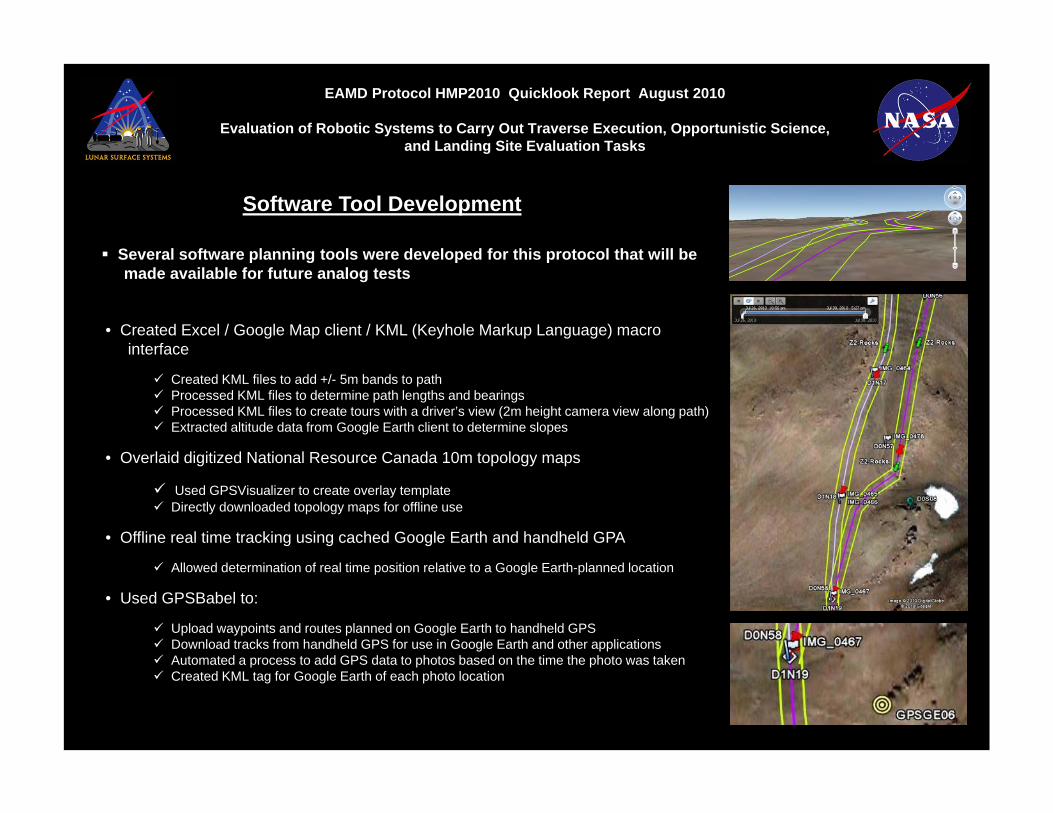
EAMD Protocol HMP2010 Quicklook Report August 2010
Evaluation of Robotic Systems to Carry Out Traverse Execution, Opportunistic Science, and Landing Site Evaluation Tasks
Software Tool Development
• Created Excel / Google Map client / KML (Keyhole Markup Language) macrointerface
Created KML files to add +/- 5m bands to path Processed KML files to determine path lengths and bearings Processed KML files to create tours with a driver’s view (2m height camera view along path) Extracted altitude data from Google Earth client to determine slopes
• Overlaid digitized National Resource Canada 10m topology maps
Used GPSVisualizer to create overlay template Directly downloaded topology maps for offline use
• Offline real time tracking using cached Google Earth and handheld GPA
Allowed determination of real time position relative to a Google Earth-planned location
• Used GPSBabel to:
Upload waypoints and routes planned on Google Earth to handheld GPS Download tracks from handheld GPS for use in Google Earth and other applications Automated a process to add GPS data to photos based on the time the photo was taken Created KML tag for Google Earth of each photo location
Several software planning tools were developed for this protocol that will bemade available for future analog tests
EAMD Protocol HMP2010 Quicklook Report August 2010
Evaluation of Robotic Systems to Carry Out Traverse Execution, Opportunistic Science, and Landing Site Evaluation Tasks
Terrain Zone Classification System
An EAMD-developed terrain classification system was used by the Traverse Route Planning & Followingand Landing Site Validation teams to consistently assess the type of terrain encountered in theirrespective experiments
First field use of this terrain zone classification system
Terrain classification system was used during both the planning phase (i.e., using remote observation datasets) and the execution phase (i.e., using data gathered at surface level)
Preliminary observations and suggested improvements have already been passed to EAMD; some of thesewill be implemented at annual Desert RATS field test, others will be topics of discussion after Desert RATS