26
TRAX RetroWave R-1 MIDI-Controlled Analogue Synthesizer Owner’s Manual
TRAX
RetroWave R-1
MIDI-Controlled
Analogue Synthesizer
Owner’s Manual

TRAX RetroWave Owner’s Manual
< 2 >

TRAX RetroWave Owner’s Manual
< 3 >
PLEASE READ CAREFULLY Please keep these instructions handy for future reference. Follow all safety instructions, as these guarantee correct operation of the apparatus. Do not use this apparatus near water, or allow exposure to drips or splashes. Use a soft dry cloth for cleaning, or a soft cloth lightly moistened with a mild detergent. Do not use abrasive cleaners, as these may damage the finish of the front panel or paintwork. Do not use the unit near any heat sources such as radiators, stoves, or other equipment that produces heat. Keep the top of the unit free to ensure proper ventilation. Never place objects on top of the control panel, as this could damage the printed circuit board and/or the controls. Unplug the mains power supply when the unit is not to be used for a long period. Servicing is required when the unit has been damaged through liquid spillage, exposure to rain or moisture, ingress of conducting foreign bodies, or the unit has been dropped. Do not open the case of the R-1, or attempt to repair the unit - there are no user serviceable parts inside. Opening up the unit may invalidate the guarantee. Please refer all servicing to Trax Controls, who offer after sales service at reasonable rates – see the Guarantee and Service Information page. Do not place any objects filled with liquids, such as vases, on the apparatus. Do not install the apparatus in a confined space such as a book case or similar. Never use the R-1 in the immediate vicinity of equipment that emits electromagnetic radiation, such as monitors, computers, and power units. The adapter draws a small amount of current from the ac outlet, with the R-1’s power switch in the OFF position. It will run warm when connected to the mains supply – this is normal. If the unit needs to be returned for servicing, updating or inspection, the original packaging must be used. Please retain all packaging materials for future use. Please ensure that the unit is located in a safe position for operation and storage. Dropping the unit onto a hard surface can damage the casing and internal parts, and could also cause injury.
Important Safety Instructions
TRAX RetroWave Owner’s Manual
< 4 >
Introduction 5 The Analogue Revolution Analogue Versus Digital Classic Techniques Computer Control So How Does an Analogue Synth Work? The Problem of Patching Let’s Get Connected 7 What’s in the Box? Other Equipment Required A Word About Your Ears Basic Connections Power Supply Amplifier and Speaker MIDI Input
Quick Start Guide 9 Channel Your Creativity Making it Musical The Magic of Modulation Playing With Pulse Width Filter Free-for-All Got “Auto Wah” if You Want It Noisy Noodling Random Musings Envelopes and Such The Sections in Detail 13 MIDI CHANNEL Selector GLIDE Control LFO 1 and LFO 2 Low Frequency Oscillators Voltage-Controlled Oscillator (VCO) Voltage-Controlled Filter (VCF) ADSR & Voltage-Controlled Amplifier (VCA)
Rear Panel Jack Sockets 22 Inputs Outputs Troubleshooting 23 Blank Patch Sheets 24 Guarantee and Service Information 25 Legal Notices 25 System Block Diagram 26
Contents
TRAX RetroWave Owner’s Manual
< 5 >
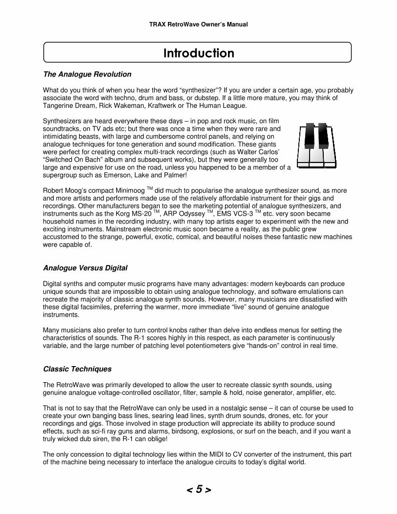
The Analogue Revolution What do you think of when you hear the word “synthesizer”? If you are under a certain age, you probably associate the word with techno, drum and bass, or dubstep. If a little more mature, you may think of Tangerine Dream, Rick Wakeman, Kraftwerk or The Human League. Synthesizers are heard everywhere these days – in pop and rock music, on film soundtracks, on TV ads etc; but there was once a time when they were rare and intimidating beasts, with large and cumbersome control panels, and relying on analogue techniques for tone generation and sound modification. These giants were perfect for creating complex multi-track recordings (such as Walter Carlos’ “Switched On Bach” album and subsequent works), but they were generally too large and expensive for use on the road, unless you happened to be a member of a supergroup such as Emerson, Lake and Palmer! Robert Moog’s compact Minimoog TM did much to popularise the analogue synthesizer sound, as more and more artists and performers made use of the relatively affordable instrument for their gigs and recordings. Other manufacturers began to see the marketing potential of analogue synthesizers, and instruments such as the Korg MS-20 TM, ARP Odyssey TM, EMS VCS-3 TM etc. very soon became household names in the recording industry, with many top artists eager to experiment with the new and exciting instruments. Mainstream electronic music soon became a reality, as the public grew accustomed to the strange, powerful, exotic, comical, and beautiful noises these fantastic new machines were capable of.
Analogue Versus Digital Digital synths and computer music programs have many advantages: modern keyboards can produce unique sounds that are impossible to obtain using analogue technology, and software emulations can recreate the majority of classic analogue synth sounds. However, many musicians are dissatisfied with these digital facsimiles, preferring the warmer, more immediate “live” sound of genuine analogue instruments. Many musicians also prefer to turn control knobs rather than delve into endless menus for setting the characteristics of sounds. The R-1 scores highly in this respect, as each parameter is continuously variable, and the large number of patching level potentiometers give “hands-on” control in real time.
Classic Techniques The RetroWave was primarily developed to allow the user to recreate classic synth sounds, using genuine analogue voltage-controlled oscillator, filter, sample & hold, noise generator, amplifier, etc. That is not to say that the RetroWave can only be used in a nostalgic sense – it can of course be used to create your own banging bass lines, searing lead lines, synth drum sounds, drones, etc. for your recordings and gigs. Those involved in stage production will appreciate its ability to produce sound effects, such as sci-fi ray guns and alarms, birdsong, explosions, or surf on the beach, and if you want a truly wicked dub siren, the R-1 can oblige! The only concession to digital technology lies within the MIDI to CV converter of the instrument, this part of the machine being necessary to interface the analogue circuits to today’s digital world.
Introduction

TRAX RetroWave Owner’s Manual
< 6 >
Computer Control Connect the R-1 to a computer via a USB to MIDI converter cable, and the possibilities are endless. Controlling the synth from a music program, you can create dazzling sequences that would be impossible to play by hand, with the freedom to adjust filter, modulation, glide and other attributes “on the fly”, without having to concentrate on playing the music itself, which is already pre-programmed.
So How Does an Analogue Synth Work? Each instrument consists of a number of electronic circuit “modules” which each have a particular function in the process of generating an electronic sound. The modules can either be totally separate, removable entities contained within a single enclosure, being interconnected via patch leads to obtain the effect required (a modular synth system) or a compact pre-patched system, in which the circuit modules are integrated onto one or more circuit boards, and are interconnected internally by means of switches and level controls (so-called “pot and switch” patching). The RetroWave falls into the latter category. Synthesizer modules consist of: Signal sources which produce the basic tones which are eventually shaped and modified to create each sound; examples are voltage-controlled oscillators, and white noise generators. External signals fed into the synth are also classed as signal sources. Signal modifiers into which the signals are fed for modification of timbre (tone quality), such as voltage-controlled filters. Controllers which are circuits that generate dc voltages and/or ac signals, used to control the operating characteristics of the previous two circuit types. An example of a controller is a MIDI to CV converter, which translates the digital data sent by MIDI musical instruments, sequencers etc, into variable voltages that are used to control the frequency of a Voltage-Controlled Oscillator, or the cutoff frequency of a Voltage-Controlled Filter.
The Problem of Patching In the RetroWave, patching between modules is achieved by closing switches and turning level controls. This is very useful for live performances, where the continual insertion and removal of patch cords would be time consuming and awkward, given the time restraints involved! That said, the R-1 has some scope for patching using 6.35mm jack cords, to give some extra flexibility when required. The absence of any patch memory might be considered a handicap by some, but in reality it can be just as fast to turn a few dials and flip a few switches to get the effects you want, as it is to go through endless menus to fetch digitally stored patches. Once you are familiar with the machine and know how it operates, you will be able to set up any sound you need with just a few deft finger movements. In the early days, patches were recalled by means of “patch sheets”. The settings of each knob and switch as used for a particular sound or effect are recorded on these, so that the patch can be reproduced at a later date. You will find some patch sheets that can be copied for your own use towards the back of the manual. TIP: Always note down the settings for a sound you particularly like, as it can often be impossible to recreate the sound at a later date if the original control settings have been forgotten!

TRAX RetroWave Owner’s Manual
< 7 >
What’s In the Box? Inside the packaging you should find:
1. The RetroWave R-1 Synthesizer, 2. A universal mains power adapter, 24V dc. 3. 1 x long ¼” (6.35mm) jack to jack output cable, 4. 2 x short ¼” jack to jack patch leads, 5. This manual.
If any of these items is missing or damaged, please contact the vendor. For safety reasons, do not use the equipment if the power unit is damaged in any way.
Other Equipment Required In addition to the R-1 and its accessories, you will need:
• An amplifier and loudspeaker system.
• Either a MIDI cable connected to an external keyboard, sequencer, etc. OR
• A USB to MIDI converter cable, connected to a computer If you want to drive the RetroWave from the CV out and gate out sockets of another piece of equipment, this can be achieved by using the rear panel input ¼” jack sockets and some optional extra jack leads. The RetroWave also sends out these signals from its internal MIDI /CV converter (the gate level is 5V), so an external synth can receive them, and play along in unison or harmony.
A Word About Your Ears
As the RetroWave is capable of producing some loud and occasionally unpredictable noises, we recommend that you do not listen at high volume levels when using headphones. This is particularly important when using the filter, which produces a much higher volume level than the VCO when in oscillator mode.
Basic Connections The basic set-up for creating music is shown overleaf, but if you want to use the R-1 simply for generating non-musical sound effects, you can omit the computer or keyboard/sequencer connections (note: the frequency range obtainable from the VCO is more restricted when the unit is not under MIDI control).
Let’s Get Connected
TRAX RetroWave Owner’s Manual
< 8 >
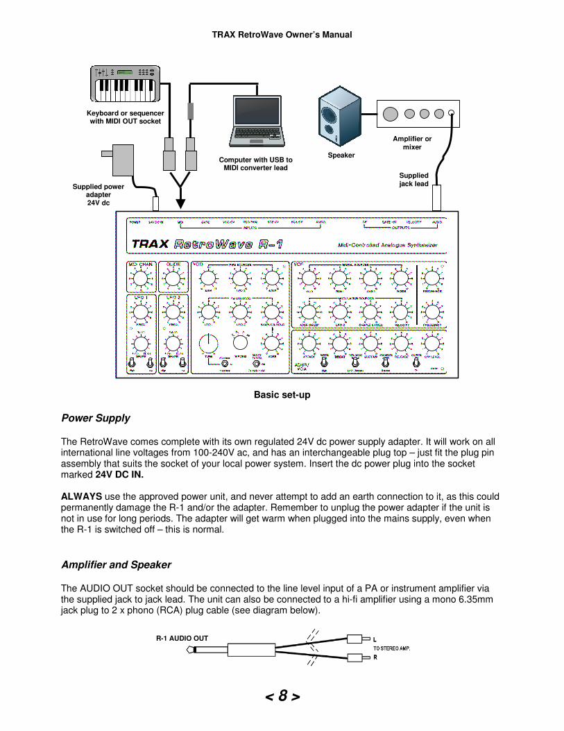
Basic set-up
Power Supply The RetroWave comes complete with its own regulated 24V dc power supply adapter. It will work on all international line voltages from 100-240V ac, and has an interchangeable plug top – just fit the plug pin assembly that suits the socket of your local power system. Insert the dc power plug into the socket marked 24V DC IN. ALWAYS use the approved power unit, and never attempt to add an earth connection to it, as this could permanently damage the R-1 and/or the adapter. Remember to unplug the power adapter if the unit is not in use for long periods. The adapter will get warm when plugged into the mains supply, even when the R-1 is switched off – this is normal.
Amplifier and Speaker The AUDIO OUT socket should be connected to the line level input of a PA or instrument amplifier via the supplied jack to jack lead. The unit can also be connected to a hi-fi amplifier using a mono 6.35mm jack plug to 2 x phono (RCA) plug cable (see diagram below).
Supplied power adapter 24V dc
Computer with USB to MIDI converter lead
Speaker
Amplifier or mixer
Keyboard or sequencer with MIDI OUT socket
Supplied jack lead
R-1 AUDIO OUT
TRAX RetroWave Owner’s Manual
< 9 >
Bear in mind that the raw waveforms generated by the RS-1 can be powerful, and can damage your speakers or amp if the latter’s volume control is set at a very high level for a long period. We recommend that you use the Aux, Tuner or Line input if using a domestic hi-fi amp, keeping the volume control at a low to medium setting, and the RS-1’s output level control low. Do not use the phono input, as this is equalized for magnetic phono cartridges, and will produce a sound lacking in treble. MIDI Input The RetroWave can be MIDI controlled by any keyboard instrument or sequencer equipped with a 5 pin DIN MIDI OUT socket. Connect the external unit to the R-1’s MIDI IN socket via a MIDI lead (5 pin plug to 5 pin plug). Do not use a normal 5-pin DIN audio lead, as these are noise-prone and may degrade the performance of the unit. The R-1 can receive MIDI messages over any one of 12 channels; just select which one you want to use by turning the rotary switch marked MIDI CHANNEL to the desired channel number. A computer can be connected via a USB to MIDI converter cable to allow sequencing, etc. from a computer program. This is a cable with a USB plug at one end, a 5 pin DIN plug at the other, and a small box of electronics strung between the two, inside which the computer data is converted into a MIDI signal that the R-1 can use. They are available at reasonable cost from online suppliers such as Amazon. Make sure that the converter lead has been recognised by the computer BEFORE starting the computer program, otherwise no MIDI signals will be sent to the R-1. The RetroWave itself does not require any drivers to be installed, and does not need to be recognized by the computer, as it is only receiving data. Just connect the lead to the computer, start the program, switch on the RetroWave, and away you go.
OK, let’s prepare for launch! This guide is not comprehensive, but simply runs through some of the unit’s capabilities without going into too much technical detail. For full technical descriptions of each module, see “The Sections in Detail” on page 12. Before applying the power, make sure that the RetroWave’s various knobs and switches are set as shown on page 9: this will ensure that you hear some sound immediately, without having to fiddle with the controls to get a signal. Throughout the guide, we will assume that you have connected a MIDI keyboard, sequencer or computer (the latter via a USB to MIDI interface lead) to the MIDI input socket. If at any time you get lost while experimenting, switch off and set the controls as shown in the diagram. That way, you will have a fresh canvas and can start again from scratch. Tip: Some controls, such as LFO FREQUENCY and SHAPE, GLIDE, TUNE, and the W’FORM switch, can be in any position when re-starting, as they do not affect the audibility of the VCO signal.
Quick Start Guide
TRAX RetroWave Owner’s Manual
< 10 >
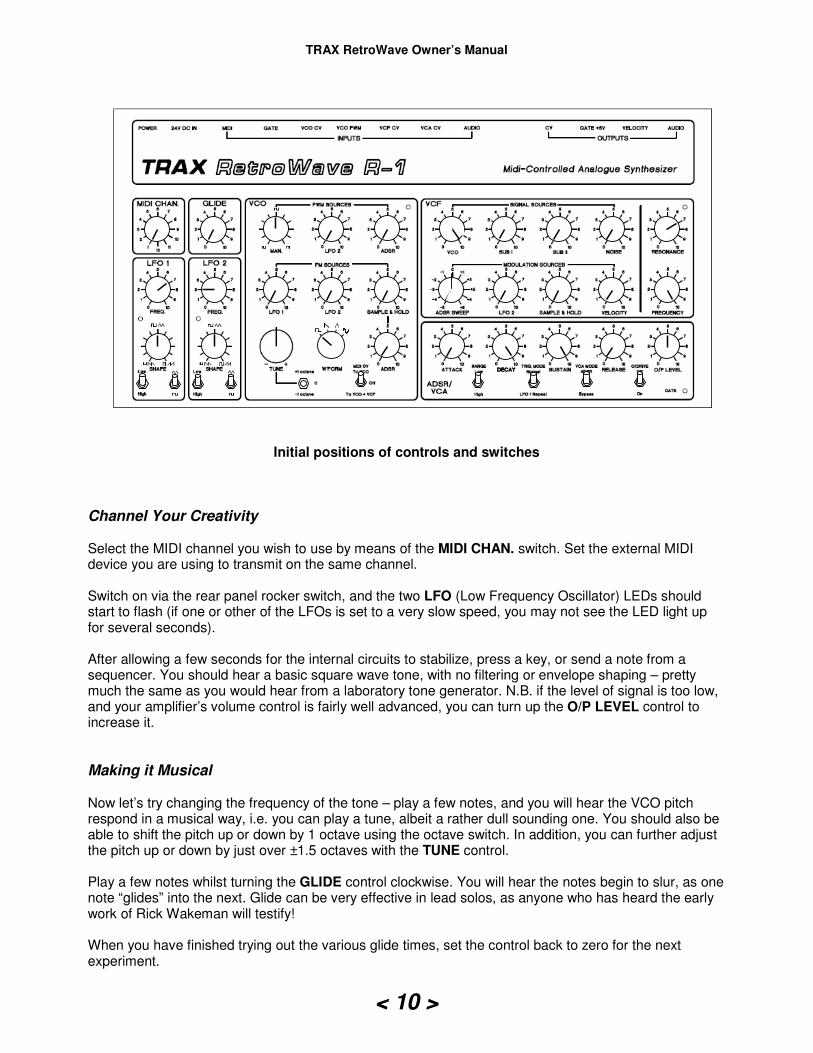
Initial positions of controls and switches
Channel Your Creativity Select the MIDI channel you wish to use by means of the MIDI CHAN. switch. Set the external MIDI device you are using to transmit on the same channel. Switch on via the rear panel rocker switch, and the two LFO (Low Frequency Oscillator) LEDs should start to flash (if one or other of the LFOs is set to a very slow speed, you may not see the LED light up for several seconds). After allowing a few seconds for the internal circuits to stabilize, press a key, or send a note from a sequencer. You should hear a basic square wave tone, with no filtering or envelope shaping – pretty much the same as you would hear from a laboratory tone generator. N.B. if the level of signal is too low, and your amplifier’s volume control is fairly well advanced, you can turn up the O/P LEVEL control to increase it.
Making it Musical Now let’s try changing the frequency of the tone – play a few notes, and you will hear the VCO pitch respond in a musical way, i.e. you can play a tune, albeit a rather dull sounding one. You should also be able to shift the pitch up or down by 1 octave using the octave switch. In addition, you can further adjust the pitch up or down by just over ±1.5 octaves with the TUNE control. Play a few notes whilst turning the GLIDE control clockwise. You will hear the notes begin to slur, as one note “glides” into the next. Glide can be very effective in lead solos, as anyone who has heard the early work of Rick Wakeman will testify! When you have finished trying out the various glide times, set the control back to zero for the next experiment.
TRAX RetroWave Owner’s Manual
< 11 >
The Magic of Modulation Now, let’s see how the Low Frequency Oscillators LFO 1 and LFO 2 can make a contribution. Play another note and keep it sounding, then turn the VCO - FM SOURCES - LFO 1 control slightly to the right; you will hear a pleasant warbling sound, as the LFO’s triangle waveform frequency modulates the VCO control voltage input. This type of gentle modulation is called vibrato, and it is very useful for adding some expression to musical tones that might otherwise sound uninteresting. Increase the modulation further, and the sound ceases to be recognisable as a musical note: it disintegrates into hyper-modulation, which is great for special effects like sirens, futuristic ray guns, etc. You can change the setting of the LFO FREQ. control to see the wide range of effects available. Low frequencies at a low to medium depth are playable over the range of a keyboard, but high modulating frequencies (selectable using the High switch setting) are only playable over part of the musical compass. Next, adjust the LFO’s SHAPE control: it will vary the slopes of the triangle wave, giving various rising and falling tones. Switch the wave shape of the LFO to square, and you should hear two tones played one after the other, ad infinitum. Increasing the LFO FM depth control on the VCO will make the spacing between the two notes greater. This facility is good for “trills” when playing tunes on the keyboard. LFO 2 works in exactly the same way as LFO 1, and both outputs feed the VCO CV input – this allows you to mix the various waveforms in varying proportions, for even stranger special effects! Try changing the VCO waveform with the W’FORM switch – you can then compare and contrast the sound of each. You can see detailed descriptions of these four wave shapes in the next section. To give some randomness to the notes you play, turn up the VCO - FM SOURCES – SAMPLE & HOLD control. Note how the pitch range of random notes increases as the control is advanced. The speed of the random notes can also be changed, by altering the setting of the LFO 1 FREQ. control. The VCO – FM SOURCES – ADSR control will be discussed shortly, under the ADSR/VCA description.
Playing with Pulse Width Next, set the controls back to the starting position, and we will investigate the pulse-width modulation of the VCO square wave. Play a note, hold it, and then advance the VCO – PWM SOURCES – MAN. control. You will hear the square wave’s sound change in character, as the mark to space ratio of the wave is varied from one extreme to another, i.e. from a short “mark” and long “space”, through 1:1 square, to long “mark” and short “space”. You can automate this process by turning up VCO – PWM SOURCES – LFO 2, so that the LFO 2 triangle wave modulates the PWM input periodically (note that this effect works best with the MAN. control in centre position, to give the square wave its full range of pulse width variation). Now that you have a basic tone with some interesting variations, you can try adding some sub-octaves to fatten it up. Turn up SUB-OCTAVE I, and you will hear a square wave that is exactly one octave below the VCO frequency, mixed in with the VCO signal. Turn up SUB-OCTAVE II, and you will hear another square wave, pitched at an octave below the first sub-octave (two octaves below the VCO).
TRAX RetroWave Owner’s Manual
< 12 >
Filter Free-for-All Next, we come to one of the most important modules in the R-1, the Voltage Controlled Filter (VCF). The filter works best with square, reverse sawtooth and triangle waveforms; sine waves, having no harmonics, will come out of the filter in much the same way as they went in! At the moment, the filter is set to pass all frequencies without attenuation. The RESONANCE control should be at halfway position; if you now turn the FREQUENCY control to and fro, you will hear the familiar synthesizer “wah” effect, which characterises the instrument and makes it so unique. As you turn the FREQUENCY control down towards zero, the sharp edges of the square wave signal are “rounded off” as the filter removes the top range of frequencies. Turning this control fully anti-clockwise will fade out the signal completely, as the audio frequencies are filtered out entirely.
Got “Auto Wah” if You Want It You can achieve a periodic, automatic “wah” effect, by turning up the VCF – MODULATION SOURCES – LFO 2 control, which will modulate the cut-off frequency of the filter automatically. Adjust LFO 2’s FREQUENCY control to alter the rate of “wahs”. Turning the RESONANCE control further clockwise will make the sound “juicier”, and eventually a point will be reached where the filter oscillates, producing a roughly sinusoidal waveform that can be played like a VCO – more details can be found in the Voltage-Controlled Filter section later. Turning RESONANCE down towards minimum will make the sound subjectively louder and more “boomy”. This setting has many uses, especially where a sound needs to have plenty of body and substance, such as a killer bass line.
Noisy Noodling In addition to the VCO, there is another signal source available - white noise. Turn down the VCO, SUB I and SUB II level controls to zero, turn down the VCF – MODULATION SOURCES – LFO 2 control to zero, and advance the NOISE control; you will hear a distinctive “hissing” sound. This noise is useful for adding breath effects to flute sounds, creating surf and rain effects or similar, and can be the basis of explosive sounds such as gunshots, snare drums etc. when used with the ADSR.
Random Musings To get a random modulation of the VCF cut-off frequency, you an also apply the same random voltage signal we sent to the VCO earlier, by turning the VCF – MODULATION SOURCES – SAMPLE & HOLD control clockwise. Keep the filter RESONANCE control near oscillation setting to get the best effect.
Envelopes and Such OK, so what next? Our basic sound now needs some shaping, to give each note played a distinctive character of its own. The way we do this is to set up an envelope for the sound using the ADSR/VCA module. This comprises the ADSR (Attack – Decay - Sustain – Release) circuit and a Voltage-Controlled Amplifier (VCA). The ADSR sends a one-shot control waveform to the VCA each time it receives a gate signal, thus controlling the contour of the final sound that is sent to the external amplifier.
TRAX RetroWave Owner’s Manual
< 13 >
Try setting the ADSR controls to Attack – 0 (fully anti-clockwise), Decay – 6, Sustain – 0, Release – 0. Play some notes, and the sound will have a envelope reminiscent of a plucked instrument, the sound starting abruptly but decaying more slowly, even when the key is held down. Now turn Sustain up to 2, and play another note – this time, the note stays “on” for as long as the note is played, but at a lower audio level. Turning Release up to 10 will now add another dimension – this time, the note will play as before, but as soon as the gate is removed, the sound will die away slowly towards silence. Try the above again, but with ATTACK set to 5: this time, the sound will build up to maximum volume slowly, so that the front edge of the note appears much “softer”. You can set the ADSR controls to any positions you like to get the sounds you want, but bear in mind that the DECAY control has no effect if the SUSTAIN control is at the same setting or above. Experience with the unit will pay dividends, as you learn how to adjust these four parameters for the best effects. The ADSR contour can also be used to drive the CV inputs of the VCF and VCO. If you turn the ADSR SWEEP control on the VCF clockwise, the positive ADSR output contour will shape the timbre of the sound each time a new note is played (you will recognise the sound immediately, as it is one of the most used synthesizer effects). Turning the control in the opposite direction will give an inverse contour. You may need to adjust the VCF FREQUENCY control to get the best effect. In the case of the VCO, turning the VCO – FM SOURCES - ADSR sweep control clockwise will introduce a pitch shift each time a new note is played, the most musical sounds being available at the lower end of the control. Note that the TUNE control will need to be adjusted to restore a playable note range, especially at high level sweep settings. Those are the basics that will set you on the road to creating sounds of your own – be sure to read the next section to learn more about the RS-1 in detail, and find out how to use the additional features not covered in the quick start guide.
Here we will discuss the RetroWave’s internal modules in depth, so you can learn how they work, and how to use them properly to create your own sounds. N.B. If you are an experienced analogue synth user, you can skip this part if you wish, and simply use it as a reference when necessary.
MIDI CHANNEL Selector
Choose from any one of 12 MIDI channels, i.e. the channel that the R-1’s MIDI to CV converter will respond to when receiving MIDI information from a connected instrument. The RetroWave is a Plug-and-Play machine that does not need to be detected by the
external equipment, as it only receives MIDI data for conversion to pitch control voltages (CVs), velocity and gate signals. Special thanks go to Trevor Page, for his excellent firmware and MIDI/CV converter design – visit his web site at www.9090project.co.uk
The Sections in Detail
TRAX RetroWave Owner’s Manual
< 14 >
GLIDE Control
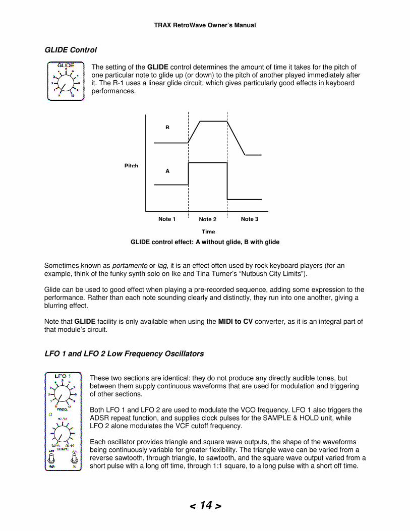
The setting of the GLIDE control determines the amount of time it takes for the pitch of one particular note to glide up (or down) to the pitch of another played immediately after it. The R-1 uses a linear glide circuit, which gives particularly good effects in keyboard performances.
GLIDE control effect: A without glide, B with glide
Sometimes known as portamento or lag, it is an effect often used by rock keyboard players (for an example, think of the funky synth solo on Ike and Tina Turner’s “Nutbush City Limits”). Glide can be used to good effect when playing a pre-recorded sequence, adding some expression to the performance. Rather than each note sounding clearly and distinctly, they run into one another, giving a blurring effect. Note that GLIDE facility is only available when using the MIDI to CV converter, as it is an integral part of that module’s circuit.
LFO 1 and LFO 2 Low Frequency Oscillators
These two sections are identical: they do not produce any directly audible tones, but between them supply continuous waveforms that are used for modulation and triggering of other sections. Both LFO 1 and LFO 2 are used to modulate the VCO frequency. LFO 1 also triggers the ADSR repeat function, and supplies clock pulses for the SAMPLE & HOLD unit, while LFO 2 alone modulates the VCF cutoff frequency. Each oscillator provides triangle and square wave outputs, the shape of the waveforms being continuously variable for greater flexibility. The triangle wave can be varied from a reverse sawtooth, through triangle, to sawtooth, and the square wave output varied from a short pulse with a long off time, through 1:1 square, to a long pulse with a short off time.
Note 1 Note 2 Note 3
Time
Pitch
B
A
TRAX RetroWave Owner’s Manual
< 15 >
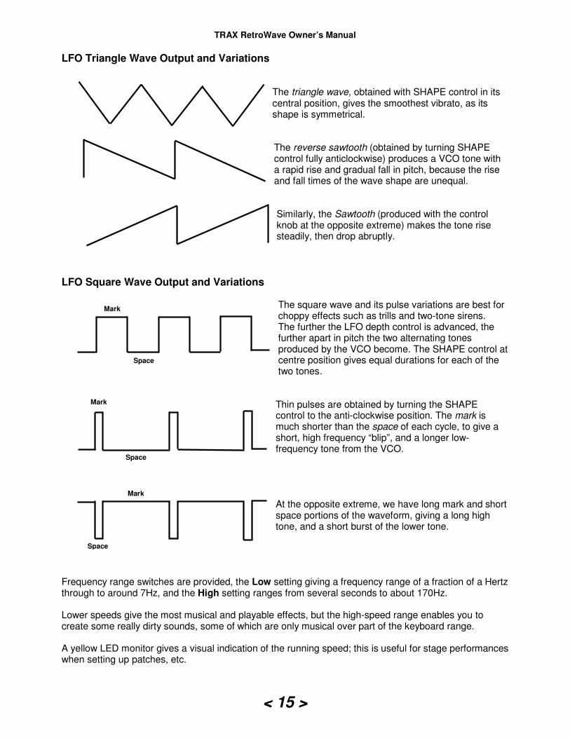
LFO Triangle Wave Output and Variations
The triangle wave, obtained with SHAPE control in its central position, gives the smoothest vibrato, as its shape is symmetrical. The reverse sawtooth (obtained by turning SHAPE control fully anticlockwise) produces a VCO tone with a rapid rise and gradual fall in pitch, because the rise and fall times of the wave shape are unequal.
Similarly, the Sawtooth (produced with the control knob at the opposite extreme) makes the tone rise steadily, then drop abruptly.
LFO Square Wave Output and Variations
The square wave and its pulse variations are best for choppy effects such as trills and two-tone sirens. The further the LFO depth control is advanced, the further apart in pitch the two alternating tones produced by the VCO become. The SHAPE control at centre position gives equal durations for each of the two tones.
Thin pulses are obtained by turning the SHAPE control to the anti-clockwise position. The mark is much shorter than the space of each cycle, to give a short, high frequency “blip”, and a longer low-frequency tone from the VCO. At the opposite extreme, we have long mark and short space portions of the waveform, giving a long high tone, and a short burst of the lower tone.
Frequency range switches are provided, the Low setting giving a frequency range of a fraction of a Hertz through to around 7Hz, and the High setting ranges from several seconds to about 170Hz. Lower speeds give the most musical and playable effects, but the high-speed range enables you to create some really dirty sounds, some of which are only musical over part of the keyboard range. A yellow LED monitor gives a visual indication of the running speed; this is useful for stage performances when setting up patches, etc.
Mark
Space
Space
Mark
Mark
Space
TRAX RetroWave Owner’s Manual
< 16 >
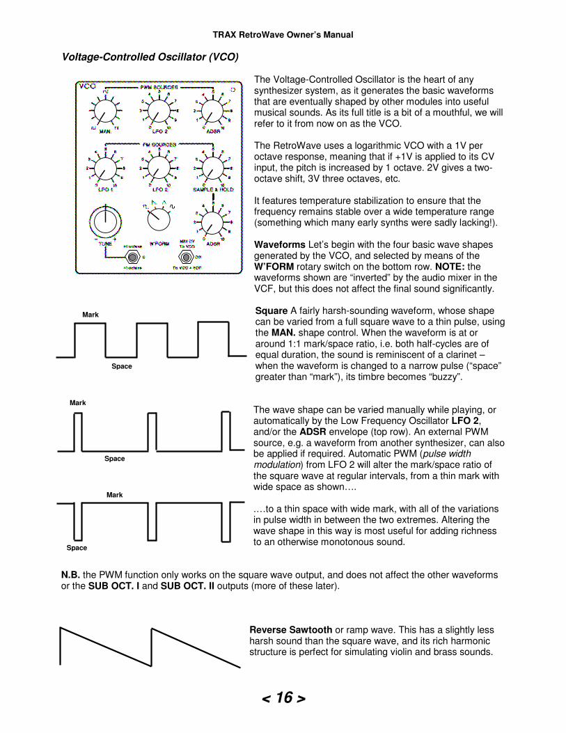
Voltage-Controlled Oscillator (VCO) The Voltage-Controlled Oscillator is the heart of any synthesizer system, as it generates the basic waveforms that are eventually shaped by other modules into useful musical sounds. As its full title is a bit of a mouthful, we will refer to it from now on as the VCO. The RetroWave uses a logarithmic VCO with a 1V per octave response, meaning that if +1V is applied to its CV input, the pitch is increased by 1 octave. 2V gives a two-octave shift, 3V three octaves, etc. It features temperature stabilization to ensure that the frequency remains stable over a wide temperature range (something which many early synths were sadly lacking!). Waveforms Let’s begin with the four basic wave shapes generated by the VCO, and selected by means of the W’FORM rotary switch on the bottom row. NOTE: the waveforms shown are “inverted” by the audio mixer in the VCF, but this does not affect the final sound significantly.
Square A fairly harsh-sounding waveform, whose shape can be varied from a full square wave to a thin pulse, using the MAN. shape control. When the waveform is at or around 1:1 mark/space ratio, i.e. both half-cycles are of equal duration, the sound is reminiscent of a clarinet – when the waveform is changed to a narrow pulse (“space” greater than “mark”), its timbre becomes “buzzy”.
The wave shape can be varied manually while playing, or automatically by the Low Frequency Oscillator LFO 2, and/or the ADSR envelope (top row). An external PWM source, e.g. a waveform from another synthesizer, can also be applied if required. Automatic PWM (pulse width modulation) from LFO 2 will alter the mark/space ratio of the square wave at regular intervals, from a thin mark with wide space as shown…. .…to a thin space with wide mark, with all of the variations in pulse width in between the two extremes. Altering the wave shape in this way is most useful for adding richness to an otherwise monotonous sound.
N.B. the PWM function only works on the square wave output, and does not affect the other waveforms or the SUB OCT. I and SUB OCT. II outputs (more of these later).
Reverse Sawtooth or ramp wave. This has a slightly less harsh sound than the square wave, and its rich harmonic structure is perfect for simulating violin and brass sounds.
Mark
Space
Mark
Space
Space
Mark
TRAX RetroWave Owner’s Manual
< 17 >
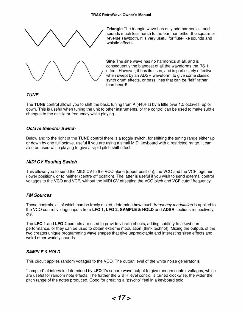
Triangle The triangle wave has only odd harmonics, and sounds much less harsh to the ear than either the square or reverse sawtooth. It is very useful for flute-like sounds and whistle effects.
Sine The sine wave has no harmonics at all, and is consequently the blandest of all the waveforms the RS-1 offers. However, it has its uses, and is particularly effective when swept by an ADSR waveform, to give some classic synth drum effects, or bass lines that can be “felt” rather than heard!
TUNE The TUNE control allows you to shift the basic tuning from A (440Hz) by a little over 1.5 octaves, up or down. This is useful when tuning the unit to other instruments, or the control can be used to make subtle changes to the oscillator frequency while playing.
Octave Selector Switch Below and to the right of the TUNE control there is a toggle switch, for shifting the tuning range either up or down by one full octave, useful if you are using a small MIDI keyboard with a restricted range. It can also be used while playing to give a rapid pitch shift effect.
MIDI CV Routing Switch This allows you to send the MIDI CV to the VCO alone (upper position), the VCO and the VCF together (lower position), or to neither (centre off position). The latter is useful if you wish to send external control voltages to the VCO and VCF, without the MIDI CV offsetting the VCO pitch and VCF cutoff frequency.
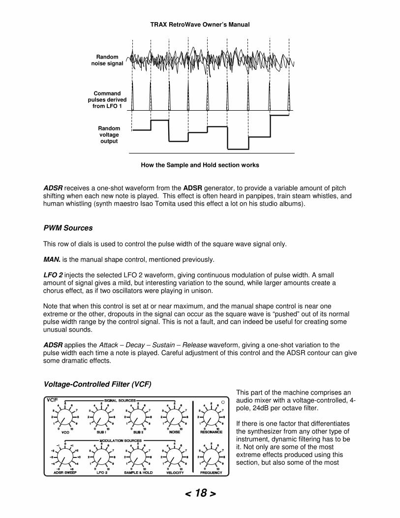
FM Sources These controls, all of which can be freely mixed, determine how much frequency modulation is applied to the VCO control voltage inputs from LFO 1, LFO 2, SAMPLE & HOLD and ADSR sections respectively, q.v. The LFO 1 and LFO 2 controls are used to provide vibrato effects, adding subtlety to a keyboard performance, or they can be used to obtain extreme modulation (think techno!). Mixing the outputs of the two creates unique programming wave shapes that give unpredictable and interesting siren effects and weird other-worldly sounds. SAMPLE & HOLD This circuit applies random voltages to the VCO. The output level of the white noise generator is “sampled” at intervals determined by LFO 1’s square wave output to give random control voltages, which are useful for random note effects. The further the S & H level control is turned clockwise, the wider the pitch range of the notes produced. Good for creating a “psycho” feel in a keyboard solo.
TRAX RetroWave Owner’s Manual
< 18 >
How the Sample and Hold section works
ADSR receives a one-shot waveform from the ADSR generator, to provide a variable amount of pitch shifting when each new note is played. This effect is often heard in panpipes, train steam whistles, and human whistling (synth maestro Isao Tomita used this effect a lot on his studio albums).
PWM Sources This row of dials is used to control the pulse width of the square wave signal only. MAN. is the manual shape control, mentioned previously. LFO 2 injects the selected LFO 2 waveform, giving continuous modulation of pulse width. A small amount of signal gives a mild, but interesting variation to the sound, while larger amounts create a chorus effect, as if two oscillators were playing in unison. Note that when this control is set at or near maximum, and the manual shape control is near one extreme or the other, dropouts in the signal can occur as the square wave is “pushed” out of its normal pulse width range by the control signal. This is not a fault, and can indeed be useful for creating some unusual sounds. ADSR applies the Attack – Decay – Sustain – Release waveform, giving a one-shot variation to the pulse width each time a note is played. Careful adjustment of this control and the ADSR contour can give some dramatic effects.
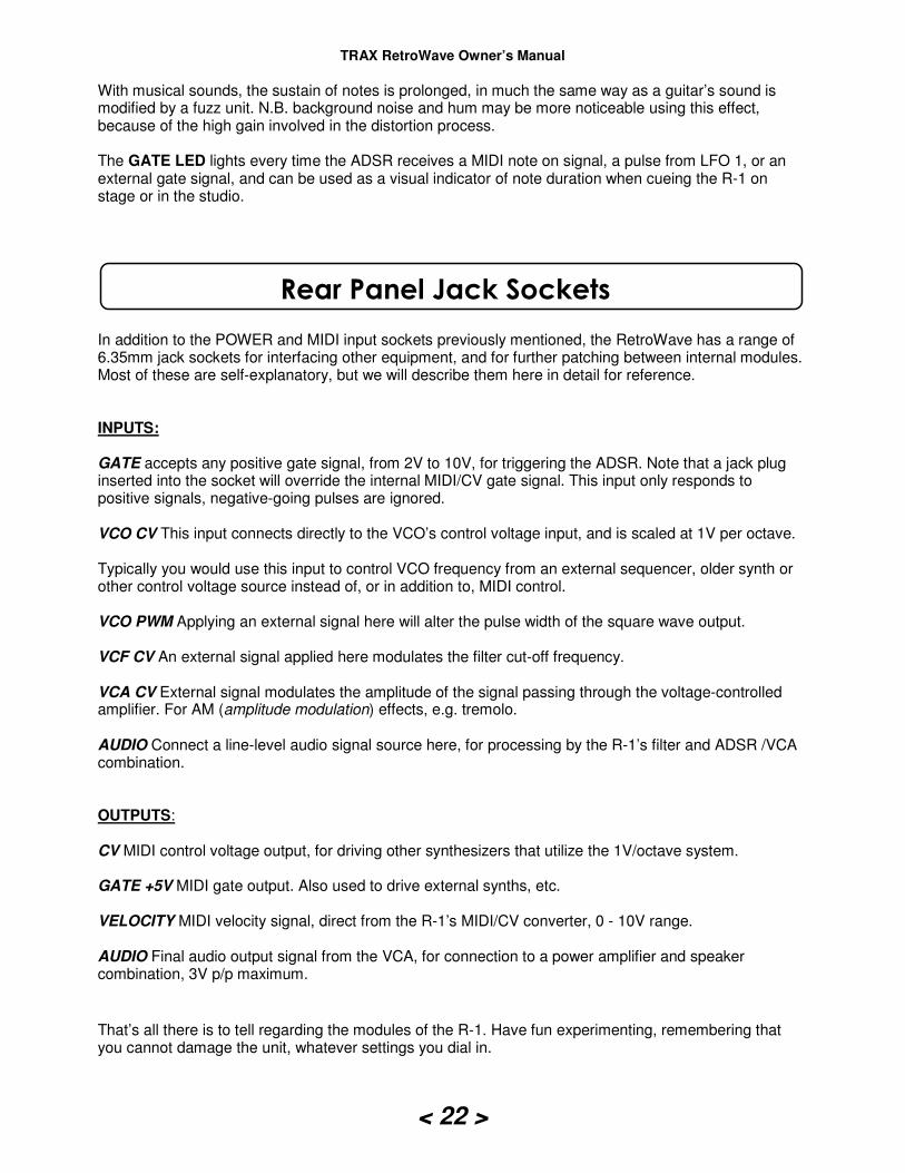
Voltage-Controlled Filter (VCF) This part of the machine comprises an audio mixer with a voltage-controlled, 4-pole, 24dB per octave filter. If there is one factor that differentiates the synthesizer from any other type of instrument, dynamic filtering has to be it. Not only are some of the most extreme effects produced using this section, but also some of the most
Random noise signal
Command pulses derived
from LFO 1
Random voltage output

TRAX RetroWave Owner’s Manual
< 19 >
subtle and interesting. It is really worth getting to know how it operates, as the number of sonic possibilities is greatly increased, once you know how to dial in the required parameters. The VCF is known as a low-pass filter, because it allows all frequencies below a certain “cut-off point” to pass, filtering out all signals that are above it. Starting on the extreme right of the module, we find two important controls: FREQUENCY This determines the cut-off point of the filter, and turning it clockwise allows more signal to pass, the sound becoming brighter and louder. In addition to manual frequency control, the various control voltages applied to the filter via the MODULATION SOURCES mixer can be combined, to change the cut-off point automatically. This is a powerful feature, as it allows a multitude of control voltages to be deployed simultaneously. RESONANCE Turning this control clockwise increases the emphasis on a narrow band of frequencies near to the filter cutoff frequency – the higher the setting, the more fluid and “fruity” the sound becomes. Advancing this control beyond the halfway setting will cause the filter to break into oscillation. This is quite normal, and can be quite a useful feature.
The oscillation frequency can be altered via the FREQUENCY control, and can in fact be tuned to the same pitch as the VCO (or set to some other musical interval), and the filter “played” along with it as an additional oscillator. The pitch accuracy over the compass of a keyboard is not as good as that of the VCO, but it is adequate for most musical applications. Note that the oscillation level produced by the filter is much higher than that produced by the VCO, so take care if using headphones. Now let’s deal with the audio mixer. This combines the outputs of five signal sources: the VCO, SUB OCTAVE I, SUB-OCTAVE II, NOISE and an external audio input (there is no level control for external signals). VCO The selected VCO waveform is applied to a level control, for mixing with the other signals in any proportion you wish. SUB-OCTAVE I is a 1:1 square wave signal, at exactly one octave below the VCO pitch, and available continuously, no matter which VCO output waveform is selected. Sub-octaves are extremely useful for fattening VCO tones, for rich bass sounds and organ-like effects. When combined with a VCO square wave that is being slowly pulse-width modulated, the resulting fat sound belies the fact that the R-1 has only one VCO. SUB-OCTAVE II is similar to SUB-OCTAVE I, but the square wave output is pitched at one octave below SUB-OCTAVE I (two octaves below VCO pitch). NOISE This controls the level of white noise applied to the mix. You may recognise it as the hissing sound heard when tuning between FM radio stations. It is a complex signal, containing all frequencies in the audio spectrum in equal amounts. In the field of electronics noise is normally something that is to be avoided at all cost, but in terms of sound synthesis it is a very useful signal source that can be used in percussive effects, rain, thunder, surf, whistle edge-noise, etc. when filtered and given a suitable envelope by the ADSR generator. External audio signals can also be added to the mix, via the AUDIO IN jack. Note that this input is only suitable for high-level sources, such as a CD or line output. Microphones will not work with this input, unless boosted by a suitable preamplifier. The external input is handy for allowing other instruments such as organs, electric pianos or other synths

TRAX RetroWave Owner’s Manual
< 20 >
to be processed by the VCF, ADSR and VCA modules. For example, an autowah effect could be set up by setting the VCA MODE switch to Bypass, turning the VCF RESONANCE control to near oscillation, and modulating the filter with a slow triangle wave from LFO 2.
Modulation Sources This part of the filter is also a mixer, but instead of audio, the various control voltages required by the filter are summed, giving a composite voltage for controlling the cutoff frequency. ADSR SWEEP This control is used to apply the one-shot ADSR waveform to the filter CV input each time a note is played. The level control can be set to give either a positive or negative filter sweep. Positive sweeps will impart a contour to the filtering that follows the same path as the VCA contour, producing a change in timbre as the note is sounded, in addition to a change in the audio envelope. The characteristic synthesizer “wah” effect is produced using this feature, and the effect is particularly pronounced with the filter RESONANCE control set to just before oscillation point. Negative sweeps will apply the inverse contour, which is great for obtaining subtle tonal changes as a note is played. Varying the ADSR controls has a great effect on the sounds produced, as does the depth of sweep applied. LFO 2 The triangle and square waveforms (and their shape variations) produced by LFO 2 can be applied in varying amounts to the filter. With the Resonance control set near to oscillation point, and a low frequency triangle selected, “auto-wah” is produced. Rapid “bubbling” effects are obtained when a high frequency is applied. Square waves give a choppy modulation that can be used for special effects. When the Resonance control is near its fully anti-clockwise position, the effect is similar to amplitude modulation or tremolo, although it is the timbre that is being modulated rather than the amplitude. SAMPLE & HOLD The random voltages produced by the S & H circuit can be applied in varying amounts, to alter the cutoff frequency in an interesting, unpredictable way. The effect is most noticeable with the RESONANCE control near or at oscillation setting, and is particularly effective with white noise. VELOCITY The control signal available from this pot is taken from the MIDI/CV converter, and is derived from MIDI velocity information encoded by the transmitting instrument. It is a voltage that varies from 0 to +10V, but the control can be used to attenuate it to lower levels if desired. The effect is to alter the filter cutoff frequency, according to the transmitted velocity value of each note.
ADSR & Voltage-Controlled Amplifier (VCA) ADSR stands for Attack, Decay, Sustain, and Release. Sometimes known as an envelope generator, this module has a dramatic effect on the final shape of a sound.
Each time a note is played, a gate signal is sent to the ADSR to trigger it. On receipt of the gate signal, the ADSR sends out a one-shot sequence of control voltages to the VCA (Voltage-Controlled Amplifier). The VCA’s output
TRAX RetroWave Owner’s Manual
< 21 >
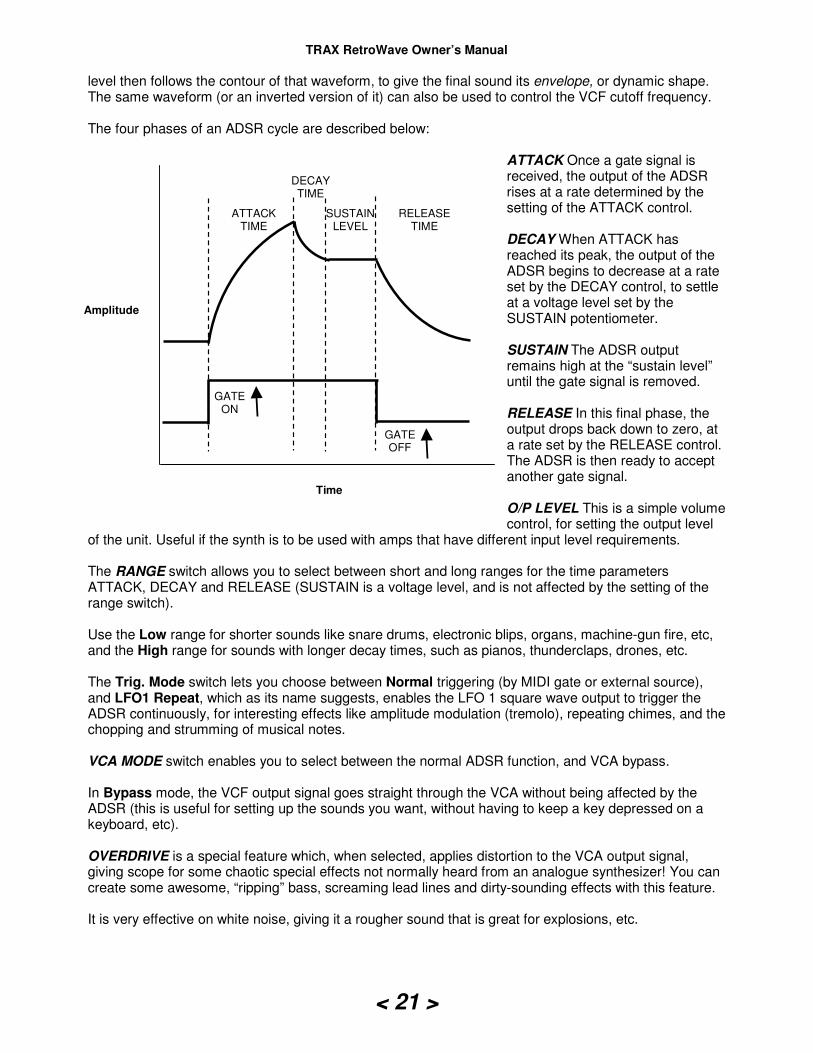
level then follows the contour of that waveform, to give the final sound its envelope, or dynamic shape. The same waveform (or an inverted version of it) can also be used to control the VCF cutoff frequency. The four phases of an ADSR cycle are described below:
ATTACK Once a gate signal is received, the output of the ADSR rises at a rate determined by the setting of the ATTACK control. DECAY When ATTACK has reached its peak, the output of the ADSR begins to decrease at a rate set by the DECAY control, to settle at a voltage level set by the SUSTAIN potentiometer. SUSTAIN The ADSR output remains high at the “sustain level” until the gate signal is removed. RELEASE In this final phase, the output drops back down to zero, at a rate set by the RELEASE control. The ADSR is then ready to accept another gate signal. O/P LEVEL This is a simple volume control, for setting the output level
of the unit. Useful if the synth is to be used with amps that have different input level requirements. The RANGE switch allows you to select between short and long ranges for the time parameters ATTACK, DECAY and RELEASE (SUSTAIN is a voltage level, and is not affected by the setting of the range switch). Use the Low range for shorter sounds like snare drums, electronic blips, organs, machine-gun fire, etc, and the High range for sounds with longer decay times, such as pianos, thunderclaps, drones, etc. The Trig. Mode switch lets you choose between Normal triggering (by MIDI gate or external source), and LFO1 Repeat, which as its name suggests, enables the LFO 1 square wave output to trigger the ADSR continuously, for interesting effects like amplitude modulation (tremolo), repeating chimes, and the chopping and strumming of musical notes. VCA MODE switch enables you to select between the normal ADSR function, and VCA bypass. In Bypass mode, the VCF output signal goes straight through the VCA without being affected by the ADSR (this is useful for setting up the sounds you want, without having to keep a key depressed on a keyboard, etc). OVERDRIVE is a special feature which, when selected, applies distortion to the VCA output signal, giving scope for some chaotic special effects not normally heard from an analogue synthesizer! You can create some awesome, “ripping” bass, screaming lead lines and dirty-sounding effects with this feature. It is very effective on white noise, giving it a rougher sound that is great for explosions, etc.
DECAY TIME
SUSTAIN LEVEL
RELEASE TIME
GATE ON
GATE OFF
ATTACK TIME
Time
Amplitude
TRAX RetroWave Owner’s Manual
< 22 >
With musical sounds, the sustain of notes is prolonged, in much the same way as a guitar’s sound is modified by a fuzz unit. N.B. background noise and hum may be more noticeable using this effect, because of the high gain involved in the distortion process. The GATE LED lights every time the ADSR receives a MIDI note on signal, a pulse from LFO 1, or an external gate signal, and can be used as a visual indicator of note duration when cueing the R-1 on stage or in the studio.
In addition to the POWER and MIDI input sockets previously mentioned, the RetroWave has a range of 6.35mm jack sockets for interfacing other equipment, and for further patching between internal modules. Most of these are self-explanatory, but we will describe them here in detail for reference. INPUTS: GATE accepts any positive gate signal, from 2V to 10V, for triggering the ADSR. Note that a jack plug inserted into the socket will override the internal MIDI/CV gate signal. This input only responds to positive signals, negative-going pulses are ignored. VCO CV This input connects directly to the VCO’s control voltage input, and is scaled at 1V per octave. Typically you would use this input to control VCO frequency from an external sequencer, older synth or other control voltage source instead of, or in addition to, MIDI control. VCO PWM Applying an external signal here will alter the pulse width of the square wave output. VCF CV An external signal applied here modulates the filter cut-off frequency. VCA CV External signal modulates the amplitude of the signal passing through the voltage-controlled amplifier. For AM (amplitude modulation) effects, e.g. tremolo. AUDIO Connect a line-level audio signal source here, for processing by the R-1’s filter and ADSR /VCA combination. OUTPUTS: CV MIDI control voltage output, for driving other synthesizers that utilize the 1V/octave system. GATE +5V MIDI gate output. Also used to drive external synths, etc. VELOCITY MIDI velocity signal, direct from the R-1’s MIDI/CV converter, 0 - 10V range. AUDIO Final audio output signal from the VCA, for connection to a power amplifier and speaker combination, 3V p/p maximum.
That’s all there is to tell regarding the modules of the R-1. Have fun experimenting, remembering that you cannot damage the unit, whatever settings you dial in.
Rear Panel Jack Sockets
TRAX RetroWave Owner’s Manual
< 23 >
Got a problem? Take a look at these possible solutions before contacting Trax for service. Some of the tips may seem obvious, but it can be very easy to overlook the simple things….
I cannot hear anything after switching the machine on Is the power supply connected and switched on at the mains? If the yellow LFO LEDs are flashing, it may just be a matter of setting the controls – see below. Have you tried setting the control knobs and switches to their initial operating positions? See “Quick Start Guide” under “Let’s Get Started”. Has the R-1’s AUDIO OUT socket been connected to a suitable amplifier and speaker? If you cannot hear anything with the W’FORM selector switch on square wave setting, but can hear the other waveforms when selected, the pulse width may be set out of range on the MAN. shape control. If so, set the control to the centre position..
The VCO is not staying in tune Always allow a few minutes after switching on before using the machine on recordings, at gigs, etc, to allow the VCO to temperature to stabilize. This will ensure that the machine stays in tune. Check also that an LFO is not modulating the VCO – if so, turn LFO 1 and LFO 2 controls in the VCO FM SOURCES section fully counter-clockwise.
Notes played on a keyboard keep sticking Check your MIDI lead – it may have an intermittent break. Substitute with another if in doubt.
The output of the VCO sounds rough When using the triangle or sine wave outputs of the VCO, make sure that the LFO 2 PWM control is at minimum, to avoid possible background noise breakthrough. Also check that the VCA OVERDRIVE switch is off.
When playing a low-level external audio source through the filter, VCO background noise can be heard Turn the TUNE control fully anti-clockwise, and set the OCTAVE switch to centre-off position.
Troubleshooting
TRAX RetroWave Owner’s Manual
< 24 >
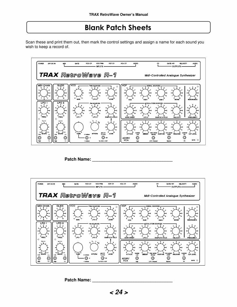
Scan these and print them out, then mark the control settings and assign a name for each sound you wish to keep a record of.
Patch Name: _________________________________
Patch Name: _________________________________
Blank Patch Sheets

TRAX RetroWave Owner’s Manual
< 25 >
We guarantee each unit for 12 months from the date of invoice, includes defective parts and labour only. The guarantee does not cover the following: damage or deterioration due to accident, mistreatment, misuse, tampering (including unauthorised circuit modifications, “circuit bending”, etc.), and connection to a non-approved power supply. Please retain all packaging and the sales receipt, for use in the event of returning the R-1 for servicing/repair. Our current repair rates are available on request. Guarantee claims can only be entertained on production of the original receipt. Please contact us by either of the following: Postal address: Trax Controls, P.O. Box 419, Norwich, NR1 3BZ Email: [email protected] Unauthorised copying, distribution or republishing prohibited without permission from the author. Although great care has been taken to ensure that this manual is free from error, responsibility cannot be accepted for any incorrect information given. Trax Controls cannot be held responsible for any damages, either physical or financial, brought about by the failure of this product, or the inability to use this product. We reserve the right to change specifications, descriptions, terms etc. at any time, without prior notice. Although this product has been manufactured to comply with EU directives and contains no lead, cadmium, chrome or mercury, it must not be disposed of through a domestic waste system. Please ensure that it is taken to a recycling centre, or returned to Trax Controls for disposal. Clipart used in this manual courtesy of www.clker.com. MIDI/CV converter based on a design by Trevor Page, who also created the MIDI firmware. See his website at: www.9090project.co.uk
RetroWave Owner’s Manual Copyright Trax Controls 2012-2013. All rights reserved. All trademarks shown in this manual remain the property of their respective owners.
Guarantee & Service Information
Legal Notices
TRAX RetroWave Owner’s Manual
< 26 >
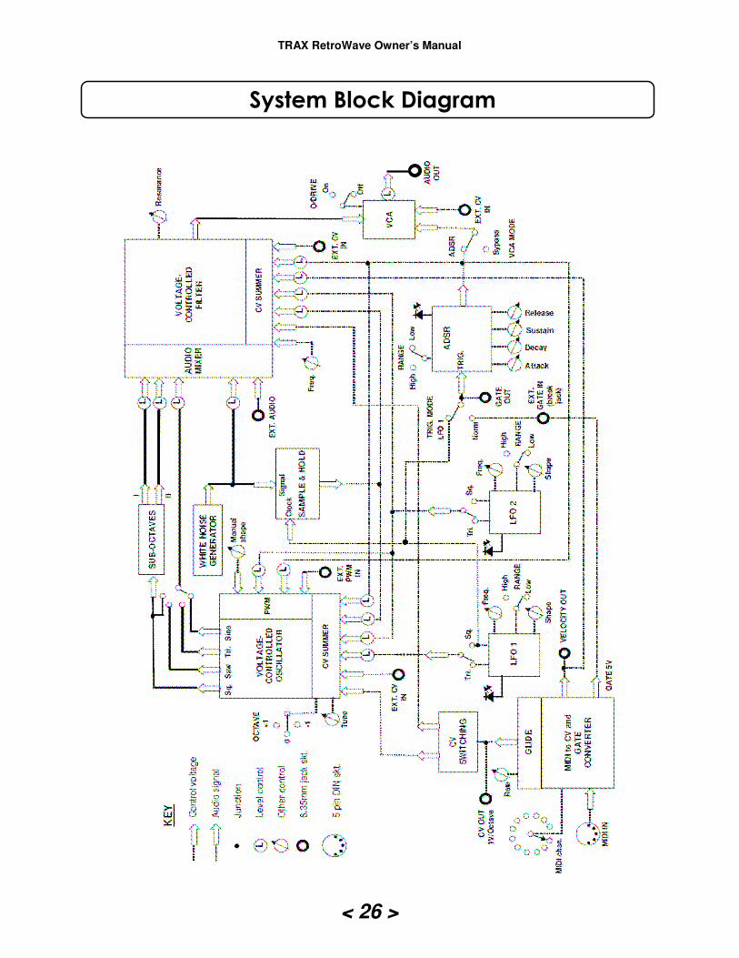
System Block Diagram


