28
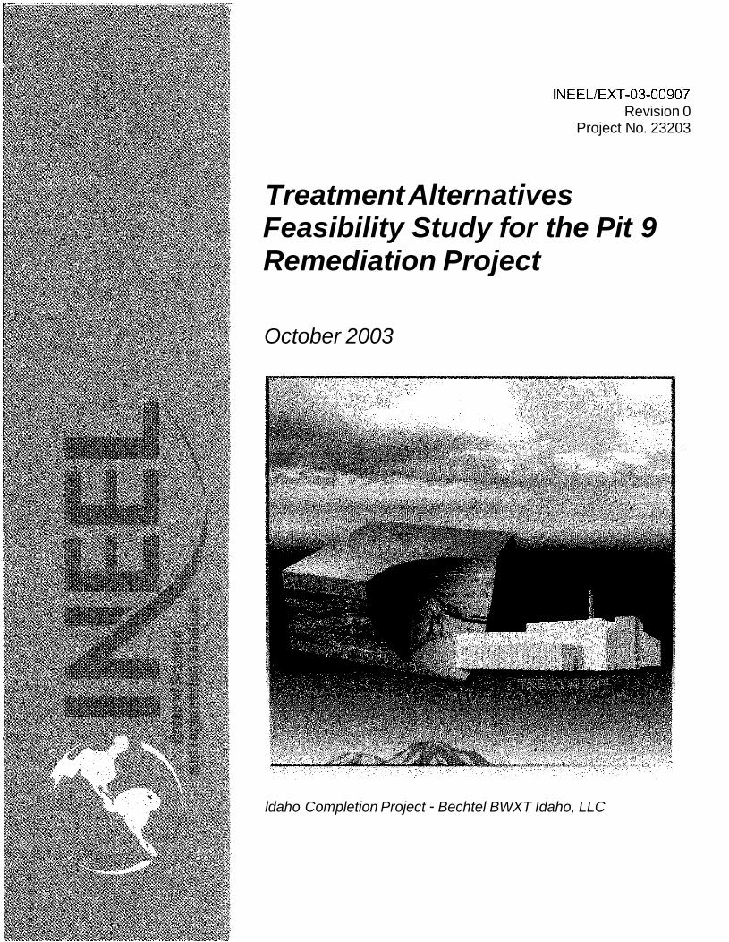
I NEEL/EXT-03-00907 Revision 0 Project No. 23203 Treatment Alternatives Feasibility Study for the Pit 9 Remediation Project October 2003 ldaho Completion Project - Bechtel BWXT Idaho, LLC
I NEEL/EXT-03-00907 Revision 0
Project No. 23203
Treatment Alternatives Feasibility Study for the Pit 9 Remediation Project
October 2003
ldaho Completion Project - Bechtel BWXT Idaho, LLC
INEEL/EXT-03-00907 Revision 0
Treatment Alternatives Feasibility Study for the Pit 9 Remediation Project
Major Contributors: William H. Landman, Jr.
Dirk Gombert Robert J. Carpenedo
Blair L. Cowley Charles L. Williams
October 2003
Idaho Completion Project Idaho Falls, Idaho 83415
Prepared for the U.S. Department of Energy
Off ice of Environmental Management Under DOE/NE Idaho Operations Office
Contract DE-AC07-991D13727
Document Type: Document Identifier: INEELEXT-03-00907 Revision No.: 0
UPL-%UG# William H. Landman, f, P.E.
/4-
Document Title: Treatment Alternatives Feasibility Study for the Pit 9 Remediation Project Project No.: 023203
9/30/03 3F.30
Project Engineer
9130103 3F30
Project Engineer
Author: William H. Landman, Jr. Phone: 526-5279
Document Owner: David E. Wilkins Phone: 526-7495
9130/03
~
SIGNATURES
REVIEW CONCURRENCE AND APPROVAL SIGNATURES Denote R for review concurrence, A for approval, ab appropriate.
3F30
Signature Signature -1 Type or Printed Name Code I Date
David E. Wilkins
Organization/
Discipline
Senior Project Manager
I I
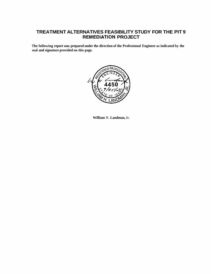
TREATMENT ALTERNATIVES FEASIBILITY STUDY FOR THE PIT 9 REMEDIATION PROJECT
The following report was prepared under the direction of the Professional Engineer as indicated by the seal and signature provided on this page.
William H. Landman, Jr.
ABSTRACT
Some of the pits and trenches located at the Subsurface Disposal Area of the Idaho National Engineering and Environmental Laboratory contain transuranic waste and other hazardous materials such as volatile organic compounds. The Federal Facilities Agreement and Consent Order between the United States Department of Energy, the Environmental Protection Agency, and the Idaho Department of Environmental Quality selected one of these pits, Pit 9, for an interim action that includes treatment of all the material in the pit that is contaminated with transuranic isotopes above the action level. The Pit 9 remediation has been separated into three stages. Stage I11 calls for the transuranic waste in the pit to be treated and shipped out of the state of Idaho and for waste not considered transuranic but containing volatile organic compounds to be treated and returned to the pit. This report documents the feasibility studies conducted for three treatment alternatives for the transuranic waste in Pit 9 that will be shipped out of state and two treatment alternatives for the volatile organic compounds contained in Pit 9 waste that will be returned to the pit. These studies provide information needed to support the Pit 9 remediation project.
... Idaho Completion Project 111
Bechtel BWXT Idaho, LLC

iv Idaho Completion Project Bechtel BWXT Idaho, LLC

EXECUTIVE SUMMARY
The Radioactive Waste Management Complex at the Idaho National Engineering and Environmental Laboratory was used for subsurface disposal of transuranic (TRU) waste in various pits and trenches of the Subsurface Disposal Area from 1952 until 1970, when the practice was suspended in favor of above-ground retrievable storage. More than 57,000 m3 of buried TRU waste (not including contaminated soil) is located within the Subsurface Disposal Area. This legacy of buried TRU waste, in part, resulted in the Laboratory being placed on the National Priorities List under the Comprehensive Environmental Response, Compensation, and Liability Act in 1989. As a result of this listing, the United States Department of Energy, the United States Environmental Protection Agency, and the Idaho Department of Environmental Quality entered into a Federal Facility Agreement and Consent Order (FFNCO).
Under the FFNCO, one of the pits used to store TRU waste, Pit 9 (designated as Operable Unit 7-10 in the FFNCO), was identified for an interim action that would demonstrate an adequate remediation approach that could be used for the rest of the TRU contaminated pits and trenches at the Subsurface Disposal Area. The original subcontract for the Pit 9 demonstration was terminated for default and the Remedial DesigdRemedial Action Scope of Work and Remedial Design Work Plan, submitted in October of 1997, established a three-staged approach to the interim action on Pit 9. The first stage of that approach, now complete, involved limited subsurface exploration using probes. The second stage, involving retrieval of soil and waste from a small portion of Pit 9, has recently completed construction and is preparing for operation. The third stage involves the complete excavation and treatment of the waste and soil in Pit 9. In Stage 111, material retrieved from the pit (estimated to be 9,900 m3 of soil and 4,250 m3 of waste, excluding the overburden) will be segregated into waste and soil streams, assayed, and the TRU and non-TRU streams will be treated as needed. At a minimum, the TRU material will be treated to meet the waste acceptance criteria for the Waste Isolation Pilot Plant in New Mexico. Fourteen options for treating the TRU material were initially identified. A screening selection process reduced these fourteen alternatives to three TRU treatment alternatives that spanned the range of cost, complexity, and volume reduction (a detailed description of each alternative is provided below). The three TRU treatment alternatives were carried forward to be developed in more detail.
Three non-TRU treatment alternatives were also identified for treatment of the primary non- radioactive contaminants of concern, volatile organic compounds. Of the three non-TRU alternatives identified, two (low temperature thermal desorption and incineration) were carried forward. Planning level designs were then developed and were used to determine capital cost and schedule estimates for Pit 9 remediation treatment systems. Each overall alternative consists of a TRU and a non-TRU option. Of the two non-TRU options, the incineration approach was much more expensive and did not provide substantial additional benefit so the thermal desorption approach was used as the non-TRU treatment with each of the three TRU treatment alternatives.
Description of Alternatives
The three alternatives considered in this study were:
Alternative 1, compact TRU material, thermal desorption of non-TRU material
Alternative 2b, melt TRU, thermal desorption of non-TRU material
Alternative 4a, segregate, incinerate, thermal desorption, and leach TRU material, thermal desorption of non-TRU materia1,Alternative 1 includes compaction of TRU material and thermal
Idaho Completion Project V
Bechtel BWXT Idaho, LLC
desorption of non-TRU material containing volatile organic compounds. This alternative has the least technical risk and lowest capital cost of the alternatives considered but also provides the least volume reduction*. In this alternative, retrieved material is segregated into waste and soil streams for assay and hrther treatment if necessary. Waste is shredded, packaged, and assayed. Containers that are contaminated with TRU at levels greater than 100 nCi/g are compacted, repackaged, stored to meet drum aging criteria for head-space gas sampling (a characterization requirement of the Waste Isolation Pilot Plant). Soil is assayed on a conveyor-based system and packaged. The soil containers with greater than 100 nCi/g TRU contamination are also stored to meet drum aging criteria for head-space gas sampling. The soil containers are not compacted because the density of the soil is already quite high and the slight compaction that could be achieved would be offset by the subsequent repackaging so that no volume reduction would be achieved (in fact, a volume increase would be more likely). The containers of TRU waste are finally certified for disposal at the Waste Isolation Pilot Plant and shipped.
Non-TRU material must pass additional decision points before being returned to the pit. If containers are found to be contaminated with uranium or polychlorinated biphenyls (PCBs) at levels greater than the corresponding action levels (which have not been established yet) they will be placed in storage until processes are developed to deal with them. Because the occurrence of PCB contamination in the Pit 9 waste is expected to be low, development of processes to treat these PCBs for small quantities at this time is not warranted. This material will be stored until the extent of contamination can be accurately determined and additional treatment operations will be added at that time if necessary. Uranium has also been identified as a contaminant of concern for the entire Subsurface Disposal Area and containers from Pit 9 with high levels of uranium will be held for treatment in systems provided for the subsequent remediation efforts.
Finally, non-TRU material that is not contaminated with PCBs or uranium but is contaminated with volatile organic compounds above action levels will be treated by low temperature thermal desorption to remove the compounds. This process involves heating the material to relatively low temperatures (175°C) under vacuum, which vaporizes the volatile organic compounds in the waste. Unfortunately, the boiling points of the compounds span that of water, so the water in the material is driven off as well. The water and compounds’ vapors are condensed and collected. The volatile organic compounds are separated from the water and packaged for shipment to an offsite treatment facility. The water is evaporated and passed through high efficiency particulate air filters before being exhausted to the atmosphere. The non-contaminated material and treated non-TRU material will be returned to the pit.
Alternative 2b includes melting of TRU material and thermal desorption of non-TRU material. This alternative has relatively low technical risk and moderate capital cost. It provides a significantly greater volume reduction of the TRU material than Alternative 1. However, it is a high temperature thermal process and community resistance to these types of technologies has been encountered in the past. As in Alternative 1, retrieved material is segregated into waste and soil streams for assay and hrther treatment, if necessary. Waste and soil are assayed separately. The waste and soil that is greater than 100 nCi/g TRU is treated in a melter located in an adjacent facility. This process produces an excellent waste form because it completely destroys the organic component of the waste, converts nitrates and other compounds to oxides, and results in an inert slag product. As a result, the head-space sampling requirements are substantially reduced. The slag is tapped directly into 40-gallon drums that are overpacked in 55-gallon drums and stored for certification and shipment to the Waste Isolation Pilot Plant. It is interesting to note that while the overall volume of waste disposed at the Waste Isolation Pilot
* The 1993 Interim Action Record of Decision currently has a goal of 90% reduction for materials undergoing treatment
vi Idaho Completion Project Bechtel BWXT Idaho, LLC

Plant is reduced, the number of shipments to the plant is almost the same as that for Alternative 1 due to the high density of the slag product and the weight limitations of the TRUPACT I1 transportation system. Off gas from the melter is treated in an off gas treatment train so that emissions from the melter will meet the requirements of the Maximum Achievable Control Technology rules for hazardous waste combustors. Also, as in Alternative 1, the material that is not contaminated with TRU at greater than 100 nCi/g is evaluated for uranium, PCB, and volatile organic compound contamination and managed accordingly. The non-contaminated material and treated non-TRU material will be returned to the pit.
Alternative 4a involves chemical leach, thermal desorption, and incineration of TRU material and thermal desorption of non-TRU material. This option has the highest technical risk, highest capital cost, and longest schedule but provides the greatest volume reduction of the TRU material. It also uses a high temperature thermal process (incineration) and therefore may also encounter greater community resistance. As in the previous alternatives, retrieved material is segregated into waste and soil streams for assay and hrther treatment if necessary. Waste and soil are assayed separately. The waste that is greater than 100 nCi/g TRU is treated in a rotary kiln incinerator located in an adjacent facility. The ash is cooled and packaged for disposal at the Waste Isolation Pilot Plant. As in Alternative 2b, the head-space sampling requirements are substantially reduced due to the thermal treatment. Off gas from the incinerator is treated in an off gas treatment train so that the emissions meet the Maximum Achievable Control Technology rules.
Alternative 4a achieves its high volume reduction of TRU waste from the chemical leaching of the soil. This study demonstrates that significant treatment of the soil is needed if the volume reductions specified in the 1993 Interim Action Record of Decision are to be met. This is, however, the most technically risky part of the process. First, soil is treated by thermal desorption to remove organic contamination. This thermal desorption system is very similar to that used on the non-TRU streams discussed above. The output from this process is directed to a chemical leach process. For this study, a nitric acid based leach process was selected, mainly based on the wide experience in the Department of Energy complex of plutonium recovery processes that used this nitric acid dissolution. It should be noted, however, that these processes were employed on well-defined streams unlike the soil material anticipated here. The soil is exposed to hot (9OOC) nitric acid for about five hours. The nitric acid dissolves the TRU contamination (and a significant fraction of the soil). The resulting slurry is filtered repeatedly to separate the liquid stream (containing the dissolved TRU) from the remaining solids. This liquid stream is then neutralized and mixed with oxalic acid, which causes the TRU and some other elements (e.g., calcium) to precipitate as oxalates. The solution is filtered and the sludge, containing the TRU, is pumped to the incinerator that is being used to treat the solid waste material.
The incineration process evaporates the water in the sludge and converts the oxalates to solid metal oxides, gaseous carbon dioxide, and water. The treated soil and liquid from the precipitation process are dried to remove the majority of the water and calcined to decompose the nitrates to nitrogen oxides. This calcining process was needed to reduce the mass of material, and in particular the mass of nitrates, being returned to the pit. The dried treated soil is packaged for return to the pit, assayed to confirm that TRU contamination levels are less than or equal to 100 nCi/g, and returned to the pit. The nitrogen oxide stream from the calciner is treated in a two-stage combustion process to reduce it to nitrogen gas, water, and carbon dioxide. If this alternative is pursued hrther, other technologies for separating TRU from the soil should be evaluated.
Once again, the material that is not contaminated with TRU at greater than 100 nCi/g is evaluated for uranium, PCB, and volatile organic compounds contaminated and managed accordingly. The non-contaminated material and treated non-TRU material will be returned to the pit.
Idaho Completion Project Bechtel BWXT Idaho, LLC vii
Technical Assessment
Trcatmcnt Altcrnatik c
The technical performance of the various alternatives is directly related to their complexity - the better the performance, the more complex and risky the approach. Of the range of alternatives considered, Alternative 1 has the least technical risk. Certainly, there are challenges with respect to minimizing cross contamination during processing, chemical compatibility of materials, and design of systems to minimize and measure plutonium hold-up but the technology employed in Alternative 1 has been demonstrated. In fact, some of the current facilities of the Advanced Mixed Waste Treatment Project at RWMC may be used.
Total Projcct Cost (SM)
Alternative 2b is considered moderately risky. In addition to the concerns noted for Alternative 1, there are additional issues related to the melter design and operation. Process development will be required to determine melter feed compositions and off gas characteristics. Design of feed and discharge systems is complicated by the high temperature operation. Plutonium hold-up concerns in the melter itself will have to be addressed. Materials selection will also be critical, especially if the melter is used to process the chlorinated organics. Finally, while not a technical concern, the resistance of surrounding communities to high temperature thermal treatment will have to be addressed.
Alternative 4a is substantially more risky than the other two alternatives. It has all the risks discussed for Alternative 1 plus a set of risks associated with the incineration system that are very similar to the melter risks discussed for Alternative 2b. In addition, the chemical leaching of the soil has never been demonstrated at production rates. The theory of the process is sound but bench scale testing with actual waste and pilot scale testing with simulants is needed to resolve process design questions. There are many mechanical issues as well, such as filter performance, pump performance with radioactively contaminated soil slurries, and high temperature calcining of soil, to name a few. These technical risks must be weighed against the potential reduction in life-cycle cost when selecting the final alternative.
Cost Results
Alternative 1 (Compact TRU Material, Thermal Desorption of non-TRU Material)
Alternative 2b (Melt TRU, Thermal Desorption of non-TRU Material)
Material. Thermal Desomtion of non-TRU Material) Alternative 4a (Segregate, Incinerate, Thermal Desorption, and Leach TRU
Total project costs (TPC) were developed for all three alternatives. These costs include development, design, construction, training, and start-up. The TPC does not include operations or decontamination and decommissioning, these costs are included in the life-cycle costs (see below). The total project costs, including escalation and contingency, for the various alternatives are shown in Table ES 1.
385.5
463.2
555.5
Table ES 1. Total Droiect cost estimates for the selected treatment alternatives.
Life-cycle costs (which include the TPCs above plus operations, decontamination, and decommissioning) were also developed as part of this study but the analyses were complicated by two factors that could not be firmly established at this time:
The total volume of waste to be retrieved
Idaho Completion Project viii Bechtel BWXT Idaho, LLC
0 The costs to be assigned to the disposal of TRU waste at the Waste Isolation Pilot Plant.
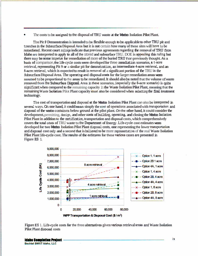
The Pit 9 Demonstration is intended to be flexible enough to be applicable to other TRU pit and trenches in the Subsurface Disposal k e a but it is not certain how many of these sites will have to be remediated Recent court rulings indicate that previous agreements regarding the removal of TRU from Idaho are interpreted to apply to all of the stored and subsurface TRU. DOE is @g this ruling but there may be m e impetus for remediation of more of the buried TRU than previously thought. As a h i s of comparison, the life-cycle costs were developed for three remediation scenarios, a l-acre retrieval, repremting Pit 9 or a similar pit for demonstration, an intmmediak 4-acre retsieval, and an B-acre rheval, which is expected to result in removal of a significant portion of the TRU in the Subsurface Disposal Area. The operating and disposal costs for the larger remediation areas were asssumed to be proportional to the areas to be remediated. It should also be noted that the volume of waste removed hi the Subsurface Disposal Area in the6 scenarios, (especially the 8-acre scenario) is quite significant when compared to the remaining capacity in the Waste Isolation Pilot Plant, meaning that the remaining Waste Isolatiofi Pilot Plant capacity must also be considered when selecting the final treatment technology.
The cost of transportation and disposal at the Waste Isolation Pilot Plant can also be interpreted in several ways. On one hand, it could mean simply the cost of operations associated with transportation and disposal of the waste containers below ground at the pilot plant. On the other hand, it could consider the development, permitting, design, and other oosts of building, opemting, and closing the Waste Is~htion Pilot Plant in addition to the certification, transportation and disposal costs, which comprehensively covers the totd c& of TRU waste to the Department of Energy. Life-cycle cost estimates were developed for two Waste Isolation Pilot Plant disposal costs, one representing the lower kanspmhtion and disposal cost only and a second that is believed to be more representative of the real Waste Isolation Pilot Plant lifeqcle cost. The results of the estimates for these various cases are presented in Figure ES 1.
B b e - -
Figure ES1, Lifecycle costs for the three alternatives given d o u s retrieval weas and Waste Isolation Pilot Plant disposal costs
It should be noted that this cost analysis, and the entire treatment system design, is predicated on the assumption that 50% of the material retrieved from the pit is TRU and this analysis is very sensitive to that assumption. If substantially less soil is TRU, the WIPP transportation and disposal costs would be much less, reducing the cost advantage of the more complex treatment processes. This reduction in TRU soil volume would also impact the estimated volume reductions, especially for Alternative 4a, because most of the volume reduction is obtained by treating the soil. At present, there is no basis to confirm or rehte this 50% assumption. Data from the Stage 11, Glovebox Excavator Method (GEM) project, currently preparing to being a small scale retrieval at Pit 9, will be very important in establishing a better basis for selecting the treatment scheme. This data is expected by the second quarter of FY-04.
Conclusions and Recommendations
The data points on the left hand side of Figure ES 1 show that Alternative 1 (Compact All) has the lowest life-cycle cost for any retrieval area if the low Waste Isolation Pilot Plant disposal costs are used. However, if the high pilot plant costs are used (right hand data points), this same alternative becomes the most expensive in all cases because of the increased volume shipped to the plant. For increasing retrieval areas, the differences between the options on either side of the graph are accentuated. In other words, as the retrieval area increases, the disposal cost becomes a larger fraction of the total cost and the unit cost at which the total disposal cost outweighs the capital and operating costs is less. At TRU waste disposal costs of at least $50Wm3, treatment to reduce waste volume begins to be cost-effective for even the one pit retrieval. For larger scale retrievals, waste disposal costs may warrant treatment to reduce Waste Isolation Pilot Plant volumes at $30Wm3.
Similarly, as the costs of transportation to and disposal at the Waste Isolation Pilot Plant costs increase, Alternative 4a becomes the lowest life-cycle costs alternative. Although, Alternative 2b (Melt All) is less expensive than Alternative 1 for some disposal costs, it is never less expensive than both of the other alternatives. If the highest Waste Isolation Pilot Plant life-cycle costs are used, Alternative 4a is always the least expensive alternative. However, Alternative 4a has the highest capital cost, is the most technically risky, and current schedule estimates do not match the milestones established for the program.
Waste Isolation Pilot Plant capacity is also an issue to be considered in the evaluation of the alternatives, and becomes increasingly important as the retrieval area increases. The total available disposal volume for contact handled waste at the pilot plant is limited by the Land Withdrawal Act to 168,520 m3. The National TRU Waste Management Plan estimates that the total volume of contact handled waste identified for disposal at WIPP is 113,300 m3. Thus, only 55,200 m3 are available for disposal of additional wastes that are not included in the plan. Any of the waste volumes generated from a 1-acre retrieval are less than 15% of “remaining” plant capacity, but as the volume of waste to be retrieved increases, this plant capacity is more severely challenged, or, in the case of Alternative 1 and an 8-acre retrieval, exceeded. Furthermore, this does not account for additional unanticipated shipments from other sites. Again, this consideration argues for alternatives with greater volume reduction.
It should also be noted that while these alternatives provide “stand-alone” capability for segregation and treatment, the Department of Energy has existing assets in the form of the Advanced Mixed Waste Treatment Project facilities. Even though a substantial portion of the capabilities of any of these alternatives would require new facilities at either site, some of the existing capabilities at the Advanced Mixed Waste Treatment Project facility such as the compactor could be used, thereby reducing the initial capital cost of Pit 9 remediation.
Idaho Completion Project X
Bechtel BWXT Idaho, LLC
Obviously, there are complex-wide issues related to this evaluation and obtaining definitive answers will be difficult and time-consuming. However, in suggesting a path forward, it should be noted that much of the capability required to segregate, assay, and package the retrieved material and treat the non-TRU fraction contaminated with volatile organic compounds is common to all the alternatives. As a path forward until additional data is available from the GEM project regarding the extent of TRU contamination in the retrieved material, decisions can be made regarding the total area to be remediated, and assessments of Waste Isolation Pilot Plant disposal costs and capacities can be agreed upon, it is recommended that the Pit 9 Remediation Project pursue the development of these common systems. There is the potential that the additional treatment capability, if needed, could be added after the GEM project is complete. It is strongly recommended that efforts to establish a consensus on the life-cycle TRU waste disposal costs continue with the National TRU Program.
Idaho Completion Project Bechtel BWXT Idaho, LLC xi

Idaho Completion Project xii Bechtel BWXT Idaho, LLC
CONTENTS ...
ABSTRACT ........................................................................................................................................... 111
EXECUTIVE SUMMARY ..................................................................................................................... v
CONTENTS ......................................................................................................................................... xiii
ACRONYMS ...................................................................................................................................... xvii
1 . INTRODUCTION ......................................................................................................................... 1 1.1 Backgr 1 1.2 Project 4 1.3 Design Basis and Assumptions ............................................................................................ 7
ALTERNATIVE DESCRIPTIONS ............................................................................................... 9 2.1 Alternative 1 (Compact All) 2.2 Alternative 2b (Melt All) ..... 2.3 Alternative 4a (Thermal Desorption, Chemical Leach, Incineration) .................................. 29
COST ESTIMATES .................................................................................................................... 47
3.2 Life-cycle Costs ................................................................................................................ 50
SCHEDULE ESTIMATES .......................................................................................................... 55
2 .
3 . 3.1 Total Project Costs 47
4 .
5 . EVALUATION OF ALTERNATIVES ....................................................................................... 59 5.1 Non-TRU Evaluation ......................................................................................................... 59 5.2 TRU Alternative Evaluation .............................................................................................. 61
6 . RISK IDENTIFICATION AND AREAS FOR FUTURE STUDY ............................................... 65 6.1 Programmatic Rwks .......................................................................................................... 66 6.2 Technical Uncertainties and Areas for Future Study ........................................................... 67 6.3 Cost Rwks ......................................................................................................................... 71 6.4 Schedule Rwks 71
. .
7 . CONCLUSIONS AND RECOMMENDATIONS ........................................................................ 73
8 . REFERENCES 75
APPENDIX A-Process Description for Waste Receiving and Preparation ......................................... A- 1
APPENDIX B-Process Description for Thermal Desorption .............................................................. B- 1
APPENDIX C-Process Description for Melting ................................................................................ C- 1
APPENDIX D-Incineration Systems Descriptions ............................................................................. D- 1
APPENDIX E-Process Description for Chemical Extraction ............................................................. .E- 1
APPENDIX F-Alternative Equipment Lists ....................................................................................... F- 1
APPENDIX G-Cost Estimates G- 1
APPENDIX H-Mass Balances .......................................................................................................... H- 1
APPENDIX I-Drawings ..................................................................................................................... .I- 1
Idaho Completion Project xiii Bechtel BWXT Idaho. LLC
FIGURES
1.
2.
3.
4.
5.
6.
7.
8.
9.
10.
11.
12.
13.
14.
15.
16.
17.
18.
19.
20.
1.
2.
3.
x1v
The Radioactive Waste Management Complex at the INEEL ......................................................... 1
Pit 9 is located within the Subsurface Disposal Area at the RWMC.. ............................................. . 2
The process used to select the five options that were studied for feasibility ... ... 4
Existing concrete pad and LMAES Retrieval Building on Pit 9 ...................................................... 5
... 6
Alternative 1 (Compact All) process flow for treatment of the TRU material ............................... 10
Physical layout of the proposed treatment and retrieval facilities for the Pit 9 remediation
Storm water detention basin with concrete catch basin and pump ..................
project. .............. ............................................................................................ 10
operator behind impact resistant windows.. ................................................... The sorting deck is used to separate the waste and soil using arms controlled remotely by an
. l l
The walking floor conveyors move the bulk material across the sorting deck ............................... 17
The conveyors in the Waste Retrieving and Preparation Facility move the waste through the assaying and separation processes ............................................................................................ 18
Apron conveyors are equipped with a dribble conveyor that catches overspill .............................. 19
.............................................................. 26
.30
.............................................................. 38
Alternative 2b (Melt All) process flow
Alternative 4a process flow ..........................................................................
Leach tawfilter operational sequence
Life-cycle costs for the three alternatives given various retrieval areas and WIPP disposal costs .................. ............................................................................................ 53
The schedule for Alternative 1 (Compact All) ................ ............................... 56
The schedule for Alternative 2b (Melt All) .................................................................................. 56
Alternative 4A schedule ................................................ ............................... 57
The life-cycle costs for Alternatives 1 and 4a, with a high and low disposal costs ........................ 63
fisk management hnctional flow diagram (DOE 2000) ............................... .65
TABLES
Treatment facility 1 -2aP demand loads ......................................................... .23
.............................................................. 24
.29
Treatment facility 1 -3aP demand load
Treatment facility 2b-3aP demand load table ................................................
Idaho Completion Project Bechtel BWXT Idaho. LLC

4. Treatment facility 4a-3aP demand load table ................................................................................ 46
5.
6.
7 .
8.
9.
10.
11.
12.
13.
Summary of costs for Alternative 1 (Compact All of the TRU Waste) plus 2aP (Incinerate the non-TRU Waste) .................................................
Desorption of the non-TRU Waste) .......
Desorption of the non-TRU Waste) .......................................................... ......... 49
Incineration of the TRU Waste) plus 3aP (Thermal Desorption of the non-TRU Waste). ............. .50
Life-cycle costs for 1 -acre retrievals ......
Life-cycle costs for 4-acre retrievals ............................................
Life-cycle costs for 8-acre retrievals ......
Evaluation of the non-TRU alternatives based on the CERCLA criteria ...........
The waste volume reduction of the three alternatives
................................................ 48
Summary of costs for Alternative 1 (Compact All of the TRU Waste) plus 3aP (Thermal 48 ..........................................................
Summary of costs for Alternative 2b (Melt All of the TRU Waste) plus 3aP (Thermal
Summary of costs for Alternative 4a (Thermal Desorption, Chemical Leach, and
52
............................ 52
..........................................................
..........................................................
................................................ 62
Idaho Completion Project Bechtel BWXT Idaho, LLC xv

Idaho Completion Project xvi Bechtel BWXT Idaho, LLC
ACRONYMS
AHU
AISC
AMWTP
ARAR
ARD
CBFO
CD
CDLR
CH
COC
DD&D
DOE
DRE
GAC
HC1
HEME
HEPA
HLLW
"03
W A C
IBC
IF
INEEL
ISF
LDR
LMAES
MACT
MTF
NOx
ou PCB
air handling unit
American Institute of Steel Construction
Advanced Mixed Waste Treatment Project
applicable or relevant and appropriate regulations
Agreement to Resolve Disputes
Carlsbad Field Office
Critical Decision
chain driven live roller conveyors
contact-handled
contaminants of concern
deactivation, decontamination, and dismantlement
Department of Energy
destruction and removal efficiency
granulated activated carbon
hydrochloric acid
high-efficiency mist eliminator
high-efficiency particulate air
high-level liquid waste
nitric acid
heating, ventilating, and air conditioning
International Building Code
Incineration Facility
Idaho National Engineering and Environmental Laboratory
Interim Storage Facility
Land Disposal Restriction
Lockheed Martin Advanced Environmental Systems
Maximum Achievable Control Technology
Melter Treatment Facility
nitrous oxide
Operable Unit
polychlorinated biphenyl
xvii Idaho Completion Project Bechtel BWXT Idaho, LLC
PM
RCRA
RH
ROD
RWMC
SCR
SMP
SNCR
svoc SWB
TD
TDF
TEC
TPC
TRU
voc WAC
WIPP
WRPF
WTF
particulate matter
Resource Conservation and Recovery Act
remote-handled
Record of Decision
Radioactive Waste Management Complex
selective catalytic reduction
shredded material packaging
selective non-catalytic reduction
semivolatile organic compound
standard waste box
Thermal Desorption
Thermal Desorption Facility
total estimated cost
total project cost
transuranic waste
volatile organic compound
waste acceptance criteria
Waste Isolation Pilot Plant
Waste Receiving and Preparation Facility
Waste Treatment Facility
xviii Idaho Completion Project Bechtel BWXT Idaho, LLC
1. INTRODUCTION
This report documents feasibility studies conducted at the Idaho National Engineering and Environmental Laboratory (INEEL) to aid in the decision making process for treating the contents of Pit 9 at the Radioactive Waste Management Complex (RWMC). Five alternatives for treatment were developed-three alternatives for treating the buried transuranic (TRU) waste found in the pit and two alternatives for the treating the non-TRU material. Each of the TRU alternatives will require one of the non-TRU alternatives to treat material removed from the pit that does not meet TRU levels but still contains contaminants of concern.
The treatment alternatives for the TRU waste are:
Alternative 1, Compact All
0 Alternative 2b, Melt All
0 Alternative 4a, Thermal Desorption, Chemical Leach and Incineration.
The treatment alternatives for the non-TRU material are:
0 Alternative 2aP, Incineration
Alternative 3aP, Thermal Desorption.
Each of these alternatives was studied for performance (volume reduction and immobilization of the contaminants), cost, and schedule in order to provide the most valuable information for deciding on the path forward for remediation of the Pit 9 contents.
1.1 Background
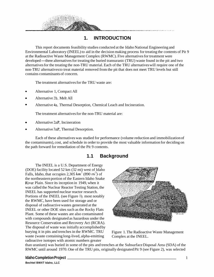
The INEEL is a U.S. Department of Energy (DOE) facility located 52 km (32 mi) west of Idaho Falls, Idaho, that occupies 2,305 km2 (890 mi2) of the northeastern portion of the Eastern Idaho Snake Ever Plain. Since its inception in 1949, when it was called the Nuclear Reactor Testing Station, the INEEL has supported nuclear reactor research. Portions of the INEEL (see Figure l), most notably the RWMC, have been used for storage and or disposal of radioactive wastes generated at the INEEL or other DOE sites such as the Rocky Flats Plant. Some of these wastes are also contaminated with compounds designated as hazardous under the Resource Conservation and Recovery Act (RCRA). The disposal of waste was initially accomplished by burying it in pits and trenches in the RWMC. TRU waste (waste containing long-lived, alpha-emitting radioactive isotopes with atomic numbers greater
Figure 1. The Radioactive Waste Management Complex at the INEEL.
than uranium) was buried in some of the pits and trenches at the Subsurface Disposal Area (SDA) of the RWMC until around 1970. One of the TRU pits, originally designated Pit 9 (see Figure 2), was selected
Idaho Completion Project 1 Bechtel BWXT Idaho, LLC

for an interim action under the Federal Facility Agreement and Consent Order that the DOE, U. S. Environmental Protection Agency, and Idaho Department of Environmental Quality entered into in 199 1.
This interim action was originally intended to involve retrieval of all the material in Pit 9 and treatment of the material that was contaminated with TRU to levels greater than 10 nCi/g. Facilities and systems were designed and constructed for this project by Lockheed Martin Advanced Environmental Systems (LMAES) but problems were encountered and matters are currently in dispute. As a result, work at Pit 9 has been divided into three stages. Stage I, which is now complete, involved limited probing of Pit 9. Stage 11, which has completed construction, involves retrieval of a limited portion of Pit 9. Stage I11 involves the retrieval of the entire contents of Pit 9 and treatment of the material that is contaminated with TRU or hazardous chemicals at levels greater than designated trigger levels. This report evaluates different alternatives that may be used to complete the treatment portion of the Pit 9 Remediation Project. Additional discussion of the regulatory background and mission need analysis can be found in the Mission Analysis and Dejnition Document (INEEL 2002) and Mission Need Statement: Pit 9 Remediation Project (DOE 2003).
Figure 2. Pit 9 is located within the Subsurface Disposal Area at the RWMC.
General knowledge about the Pit 9 contents has been gained from Stages I and 11, as well as examination of historical records of pit contents (based on shipping records). In Stage I, subsurface exploration of the pit investigated buried waste at selected locations using probes and obtained logging data. These data supported the siting of Stage 11, a small-scale waste material retrieval project, at the Pit 9 site. The construction phase of Stage 11, also called the Glovebox Excavator Method (GEM), was completed in May 2003, and the facility has been turned over to operations. The small-scale retrieval activities are scheduled to start in the fall of 2003 and be completed within three months thereafter. The GEM Project will demonstrate safe TRU waste retrieval and storage. Part of the new Pit 9 remediation project work scope includes treatment and disposal of retrieved waste from the GEM activities. Pit 9 h l l remediation planning will use lessons learned for Stages I and I1 to enhance transferability of the remediation approach to other SDA pits and trenches, as well as to provide DOE with a buried waste remediation technology to reduce risk across the DOE complex.
DOE is currently evaluating options for Stage I11 of the Pit 9 interim action, consistent with the requirements of DOE Order 413.3, “Program And Project Management for the Acquisition of Capital Assets.” As part of the Pit 9 Remediation Project, studies were conducted to evaluate alternatives for retrieval and treatment of the material in Pit 9. The study documented in this report was conducted to identify a reasonable set of alternatives that spanned the spectrum of performance, i.e., volume reduction and immobilization of the contaminants, for treating the debris and soil retrieved from Pit 9. Planning level designs were developed for these treatment alternatives and were used to generate cost estimates and schedules. The cost, schedule, and technical assessments generated for these alternatives will form part of
2 Idaho Completion Project Bechtel BWXT Idaho, LLC
the basis for decision-making with regard to performance requirements for the Pit 9 remediation project and final selection of the Pit 9 treatment alternative.
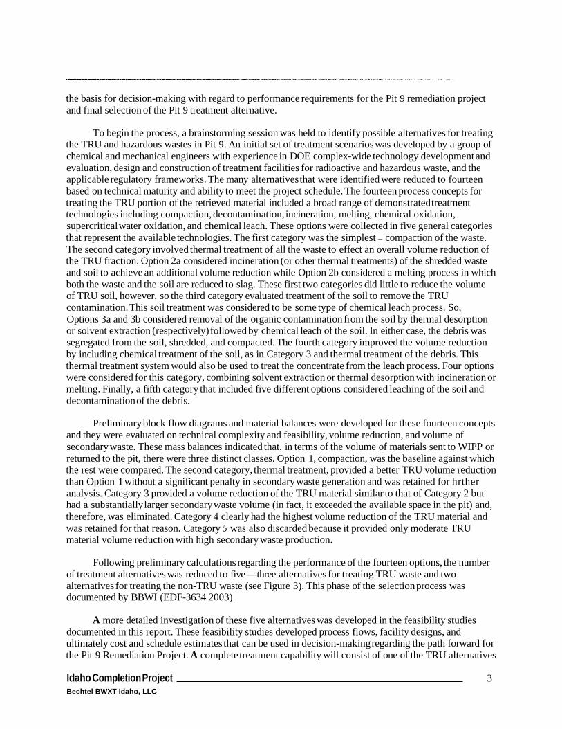
To begin the process, a brainstorming session was held to identify possible alternatives for treating the TRU and hazardous wastes in Pit 9. An initial set of treatment scenarios was developed by a group of chemical and mechanical engineers with experience in DOE complex-wide technology development and evaluation, design and construction of treatment facilities for radioactive and hazardous waste, and the applicable regulatory frameworks. The many alternatives that were identified were reduced to fourteen based on technical maturity and ability to meet the project schedule. The fourteen process concepts for treating the TRU portion of the retrieved material included a broad range of demonstrated treatment technologies including compaction, decontamination, incineration, melting, chemical oxidation, supercritical water oxidation, and chemical leach. These options were collected in five general categories that represent the available technologies. The first category was the simplest - compaction of the waste. The second category involved thermal treatment of all the waste to effect an overall volume reduction of the TRU fraction. Option 2a considered incineration (or other thermal treatments) of the shredded waste and soil to achieve an additional volume reduction while Option 2b considered a melting process in which both the waste and the soil are reduced to slag. These first two categories did little to reduce the volume of TRU soil, however, so the third category evaluated treatment of the soil to remove the TRU contamination. This soil treatment was considered to be some type of chemical leach process. So, Options 3a and 3b considered removal of the organic contamination from the soil by thermal desorption or solvent extraction (respectively) followed by chemical leach of the soil. In either case, the debris was segregated from the soil, shredded, and compacted. The fourth category improved the volume reduction by including chemical treatment of the soil, as in Category 3 and thermal treatment of the debris. This thermal treatment system would also be used to treat the concentrate from the leach process. Four options were considered for this category, combining solvent extraction or thermal desorption with incineration or melting. Finally, a fifth category that included five different options considered leaching of the soil and decontamination of the debris.
Preliminary block flow diagrams and material balances were developed for these fourteen concepts and they were evaluated on technical complexity and feasibility, volume reduction, and volume of secondary waste. These mass balances indicated that, in terms of the volume of materials sent to WIPP or returned to the pit, there were three distinct classes. Option 1, compaction, was the baseline against which the rest were compared. The second category, thermal treatment, provided a better TRU volume reduction than Option 1 without a significant penalty in secondary waste generation and was retained for hrther analysis. Category 3 provided a volume reduction of the TRU material similar to that of Category 2 but had a substantially larger secondary waste volume (in fact, it exceeded the available space in the pit) and, therefore, was eliminated. Category 4 clearly had the highest volume reduction of the TRU material and was retained for that reason. Category 5 was also discarded because it provided only moderate TRU material volume reduction with high secondary waste production.
Following preliminary calculations regarding the performance of the fourteen options, the number of treatment alternatives was reduced to five-three alternatives for treating TRU waste and two alternatives for treating the non-TRU waste (see Figure 3). This phase of the selection process was documented by BBWI (EDF-3634 2003).
A more detailed investigation of these five alternatives was developed in the feasibility studies documented in this report. These feasibility studies developed process flows, facility designs, and ultimately cost and schedule estimates that can be used in decision-making regarding the path forward for the Pit 9 Remediation Project. A complete treatment capability will consist of one of the TRU alternatives
Idaho Completion Project 3 Bechtel BWXT Idaho, LLC

and one of the non-TRU alternatives. In some cases, the processing capacity may seem to be duplicated. For instance, Alternative 4a has a TRU thermal desorption system that performs the same hnctions as its non-TRU counterpart. The use of independent TRU and non-TRU systems eliminates the real concern that a common system would tend to cross-contaminate the non-TRU stream. A single system would also require larger equipment and the storage and sequencing of the TRU and non-TRU material would complicate plant operations. Finally, a single system would require certain accommodations on the output as well. For instance, the non-TRU treated material requires cooling while the TRU stream does not.
1.2 Project Location
The project site is located near Pit 9 on the northeast corner of the SDA, immediately west of the RWMC operations area at the INEEL.
The area just to the west of Pit 9, which currently includes structures owned by LMAES, is used for roads, siting of buildings and equipment, and work area operations.
The GEM Project also includes structures that are located on or near Pit 9. Most of these structures will be removed prior to the start of construction for this project. Structures that may be left in place for hture use are described later in the report.
Requirements -L> Technology Screening
(1 4 Concepts)
Develop flow sheets volume reduction estimates
secondary waste estimates
Evaluation of options
TRU Non-TRU 3 options 2 options
Compact all Incineration 0 Melt all Thermal
desorption Leach 03-GA50388-66
Figure 3. The process used to select the five options that were studied for feasibility.
1.2.1 Site Characterization
The existing site has been modified from its natural condition. The original site soils were mostly wind deposited silts on top of lava bedrock. Pit 9 was excavated down to the lava bedrock and the backfilled with about 2 ft of soil. Waste was placed in the pit and intermittently covered with clean soil. After the pit was filled, the surface of the pit was covered with clean soil. This soil layer is estimated to range between 2.5 ft and 6 ft thick. Additional overburden has been added over the years to fill in areas of subsidence and to assist with drainage and flood control. Pit run gravel fill has been added to areas in the vicinity of existing structures outside the Pit 9 area and some areas on Pit 9. The depth to bedrock varies from a minimum of approximately 14 ft to a maximum of approximately 23 ft from the average existing grade.
1.2.2 Description of Existing Site
Pit 9 takes in a 115 x 400 ft portion of the SDA, and consists of a waste pit situated between two concrete structural pads. The pit is covered with an average of 6 feet of overburden.
4 Idaho Completion Project Bechtel BWXT Idaho, LLC

Figure 4. Existing concrete pad and LMAES Retrieval Building on Pit 9.
Existing Structures, and Facilities
The existing LMAES structures located in the Pit 9 area are the process building, retrieval building, and rail system supported by the concrete structural pads (see Figure 4). It is assumed that the buildings will be removed prior to the start of construction for Pit 9 remediation activities. The existing concrete structural pads and the steel piles supporting them will be used as part of this project. Field investigation and testing to verify the quality of the any existing structures prior to use will be required.
A storm water detention basin and a concrete catch basin that connects to an underground piping system are also located in the project area. See the following section for more information in the basins.
An existing fire riser building provides a dry pipe fire protection system for the Glovebox Excavator System project structures. This structure will be retained and used as part of this project.
SDA Storm Water Drainage and Control
The only natural source of water for the SDA and Pit 9 is precipitation in the form of rain and snow. This water will be controlled to prevent flooding of the SDA and Pit 9 area.
Localized runoff within the SDA is controlled through an existing engineered internal drainage system. SDA surface water runoff discharges to the main complex drainage channel along Adams Boulevard through the existing storm water detention basin located on the east end of the disposal Area (see Figure 5 ) . The storm water detention basin is used to collect internal runoff from the SDA for sampling before discharge to the main channel. The storm water catch basin is equipped with a sump pump. The sump pump is a 6-hp 400-gal/minute pump that is used to pump detained storm water from the detention basin through a 4 in. discharge pipe into one of two 30-in. culverts that connect to the main
Idaho Completion Project 5 Bechtel BWXT Idaho, LLC
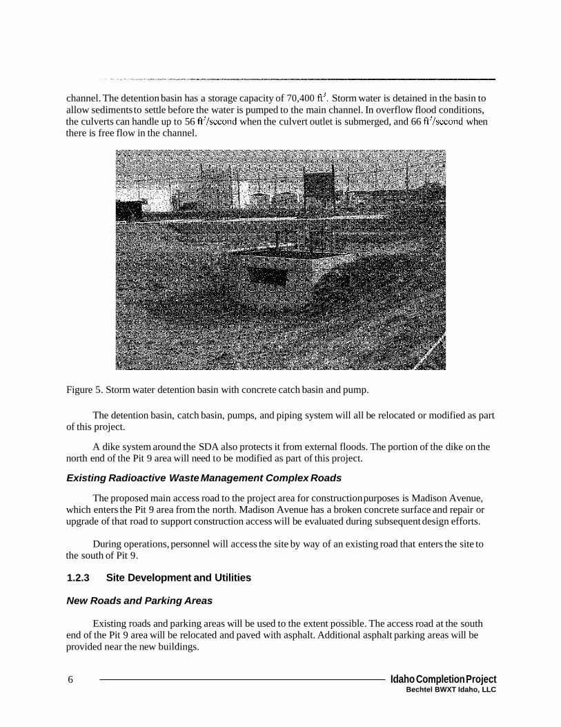
channel. The detention basin has a storage capacity of 70,400 ft3. Storm water is detained in the basin to allow sediments to settle before the water is pumped to the main channel. In overflow flood conditions, the culverts can handle up to 56 ft3/second when the culvert outlet is submerged, and 66 ft3/second when there is free flow in the channel.
Figure 5. Storm water detention basin with concrete catch basin and pump.
The detention basin, catch basin, pumps, and piping system will all be relocated or modified as part of this project.
A dike system around the SDA also protects it from external floods. The portion of the dike on the north end of the Pit 9 area will need to be modified as part of this project.
Existing Radioactive Waste Management Complex Roads
The proposed main access road to the project area for construction purposes is Madison Avenue, which enters the Pit 9 area from the north. Madison Avenue has a broken concrete surface and repair or upgrade of that road to support construction access will be evaluated during subsequent design efforts.
During operations, personnel will access the site by way of an existing road that enters the site to the south of Pit 9.
1.2.3 Site Development and Utilities
New Roads and Parking Areas
Existing roads and parking areas will be used to the extent possible. The access road at the south end of the Pit 9 area will be relocated and paved with asphalt. Additional asphalt parking areas will be provided near the new buildings.
6 Idaho Completion Project Bechtel BWXT Idaho, LLC

Gravel Fill, Culverts, Ditches, and Storm Water Drainage
The storm water drainage system will be modified to provide a new storm water detention basin. The drainage system will be modified to provide additional culverts, ditches, and fill necessary to collect and transfer storm water from the SDA to the main complex drainage channel. The sizes of the basin, culverts, and ditches will be consistent with the existing system as previously described.
The dike system around the Disposal Area will also be modified to accommodate the Treatment Building configuration.
1.3 Design Basis and Assumptions
The basis for design used in developing the feasibility studies is documented in the Mission Analysis and Dejnition Document (INEEL 2002) and Engineering Design File-3634, “Treatment Technology Screening for OU 7-10 Stage I11 Project” (2003).
The major assumptions made in developing these feasibility studies are identified below:
1.
2.
3.
4.
5 .
6.
TRU isotopes are alpha emitting isotopes with half-lives greater than 20 years and atomic numbers greater than uranium
Material contaminated with less than or equal to 100 nCi/g of TRU would be managed as follows (refer to sheet 1-PF-1 in Appendix I): - If it is contaminated with polychlorinated biphenyls (PCBs) above the action level it will be
placed in long-term storage to be managed with other material resulting from subsequent remediation efforts in the rest of the SDA
If it is contaminated with uranium above the action level it will be placed in long-term storage to be managed with other material resulting from subsequent remediation efforts in the rest of the SDA
If it is contaminated with VOCs above the action level, it will be treated in the non-TRU treatment facility before being returned to the pit.
-
-
The 1993 Interim Record of Decision (ROD) assumed that one-half the retrieved material would be contaminated with TRU isotopes at levels greater than 10 nCi/g. For lack of data on the extent of migration of TRU or other contamination, it has been assumed that one-half of the material retrieved from the pit would be contaminated with TRU isotopes at levels greater than 100 nCi/g. This was hrther interpreted to mean that 50% of the soil and 50% of the waste was contaminated with TRU isotopes at levels greater than 100 nCi/g.
Material returned to the pit must be stabilized to meet structural requirements to minimize subsidence of a hture cap. This stabilization will require filling void space in the containers returned to the pit with low strength grout.
Sortinghhredding of waste to support assay does not trigger applicability of RCRA Land Disposal Restrictions (LDR) through placement
While some alternatives provide capabilities that are very similar to those provided by the BNFL Advanced Mixed Waste Treatment Project (AMWTP), negotiations have not been conducted with
Idaho Completion Project 7 Bechtel BWXT Idaho, LLC

BNFL and no credit was taken for use of those facilities. If the alternatives that resemble the AMWTP capabilities are strong contenders (or would be if advantage were to be taken for the cost savings), these negotiations will be pursued to take the best advantage of DOE assets.
7 . Special case materials, i.e., those that cannot be returned to the pit and that cannot be treated in the provided facilities to meet the acceptance criteria at the designated disposal site will be placed in long-term storage. For instance, compressed air bottles are not accepted at WIPP and would likely be considered unsafe to return to the pit. Very few of these items are expected and it is difficult to anticipate the treatment capability that would be needed for these hypothetical cases. These items, if encountered, will be placed in a long-term storage until systems can be developed to treat them.
The existing facilities in the area that were part of the original LMAES Pit 9 project will be removed before the start of site preparation and building structure construction.
8 .
The study considered two sets of treatment requirements, those for material that was contaminated with TRU isotopes at levels greater that 100 nCi/g (designated TRU material) and those that were contaminated with TRU isotopes at levels less than or equal to 100 nCi/g (designated non-TRU material).
The TRU material will be treated as necessary to meet the Waste Isolation Pilot Plant (WIPP) waste acceptance criteria (WAC) and reduce the overall life-cycle cost of treatment, transportation, and disposal. The non-TRU material will be treated to remove contamination due to volatile organic compounds (VOCs). Treated non-TRU material will be required to meet LDRs.
The overall operating duration of the Pit 9 Remediation Project was selected to be three years, with a total of two years for actual processing. This overall three-year duration allows startup, removal of overburden, and build-up of material for treatment (6-month allowance), two years for processing, and an additional period (also a 6-month allowance) to complete closure of the pit. To allow for maintenance and other downtime, an availability of 200 days (24 hours) per year was used for sizing process equipment and systems. Based on this schedule and plant availability assumptions, the total operating duration used in the process design was 9,600 hours. For the purposes of equipment design, a plant design life of ten years will be specified. This 10-year duration is consistent with current project planning and will accommodate processing a total of four pits the size of Pit 9 (two years of operation each) plus start-up and interim operations and testing.
8 Idaho Completion Project Bechtel BWXT Idaho, LLC


