Treatment for geometry noise in mesh generation for welded tubular Y-joints in the BFM
Chenjun Lu, Jianming Zhang & Lei Han State Key Laboratory of Advanced Design and Manufacturing for Vehicle Body, Hunan University, China
Abstract
Welding seams are often omitted in stress analyses of a welded frame structure when using the finite element method. The boundary face method (BFM) makes direct use of the CAD data of a structure to perform stress analysis, and therefore has the potential to analyze a frame structure with all the welding seams taken into account. Tubular Y-joints are typical sub-structures of a frame. The CAD data of these Y-joints may contain geometric noises, which cause severe difficulties for meshing. This paper describes a method to clear automatically the possible geometric noises of a welded tubular Y-joint, so as to be easily meshed during the stress analysis process when using the BFM. The method uses B-splines to remove geometric noises and to recover the topology, and allows direct access to the consistent topology and accurate geometry of the welded tubular Y-joint for 3D surface mesh generation. Several examples of automatic meshing on complex frames are presented to validate the proposed method. Keywords: uncracked tubular Y-joint, BFM, geometrical modeling, geometry noise.
1 Introduction
Welding frames made of tubular members are extensively used in engineering due to the excellent structural and mechanical properties of the tubular members. Because of the structural discontinuity of the regions between chord and brace intersection, high stress concentration, of interest to engineers and designers, often exists in these areas. Furthermore, it always presents the problem of fatigue
Boundary Elements and Other Mesh Reduction Methods XXXVI 459
failure under cyclic loading under various conditions. Thus, a lot of researchers have focused their effort on the estimation of stress concentration factors of welded tubular joints. In the past, some researchers [1, 2] thought that it was unnecessary to model the detailed welded tubular joint in some cases, such as analyses for K-joints. As FE analyses for tubular joints, shell elements which represent the mid-surfaces of the tubular members have been widely used to reduce the computation cost needed without considering welding seams. But, recent research has shown that it is necessary to take welding seams into consideration for a more accurate prediction of joint strength and in stress concentration factor analyses [3]. Mesh generation of welded tubular Y-joints was used in this paper for the automatic data preparation for analyses in BFM [4] which is a new implementation of the boundary element method (BEM). The C0 continuous requirement for the boundary mesh makes the meshing more flexible and easy in the BFM than that in the FEM. Moreover, it is usually difficult to generate a volume mesh for welded tubular Y-joints. In the BFM, however, only a boundary mesh is required. In the BFM, cells are defined in the parametric space of each surface. In addition, the requirements for the quality and shape of cell and topological connectivity for the BFM mesh is different from that in the FEM and many existing commercial software packages including PATRAN, ANSYS and ABAQUS/ PRE are only available to generate 3D meshes for tubular joints. Such grid cells defined in 3D space are different from the cells employed in the BFM. Towards this end, without using existing grid generation tools to output the data of the BFM required, we have to develop a mesh generation module to discrete CAD surface directly. In the pre-process of the BFM, topology recovery is one of the most complex issues. It is usually difficult to develop a consistent geometrical definition for CAD and CAE software industries. There are some micro-curves, extra faces and “slivers”, which is one of the most common unwanted artificial features [5], involved in CAD data. These are introduced by the Boolean operations or system tolerance etc. in the modeling process. In this paper, these excess features are considered as geometric noises during the boundary meshing. Geometry noises usually lead to a mesh with poor quality or even lead to mesh generation failure. We try to remove these noises before the meshing. The main objective of this paper is to introduce the treatment for geometry noise of welded tubular Y-joints including geometry noise detection and topology recovery to ensure a conforming topology for subsequent surface mesh generation and analysis in the BFM. The outline of this paper is as follows. The modeling of a tubular Y-joint with a fillet weld using fusion welding will be described in Section 2. In Section 3, emphasis is given to the treatment for geometry noise and detailed topology recovery algorithm of welded tubular Y-joints. In Section 4, mesh generation examples of welded tubular Y-joints will be given to demonstrate the consistency of the geometrical model using the topology recovery method developed and further indicate the effectiveness of the method. Finally, conclusions of the current study will be summarized and some recommendations for further work will be suggested.
460 Boundary Elements and Other Mesh Reduction Methods XXXVI
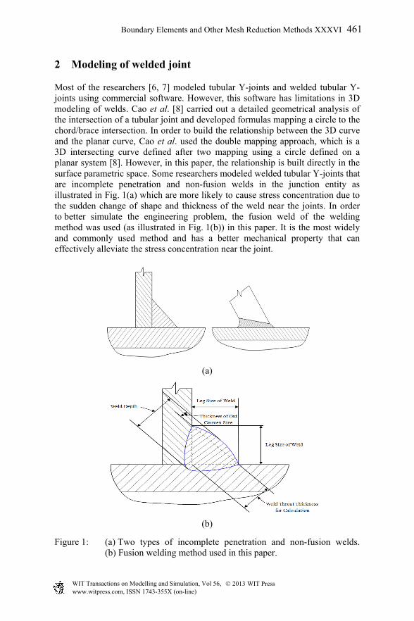
Most of the researchers [6, 7] modeled tubular Y-joints and welded tubular Y-joints using commercial software. However, this software has limitations in 3D modeling of welds. Cao et al. [8] carried out a detailed geometrical analysis of the intersection of a tubular joint and developed formulas mapping a circle to the chord/brace intersection. In order to build the relationship between the 3D curve and the planar curve, Cao et al. used the double mapping approach, which is a 3D intersecting curve defined after two mapping using a circle defined on a planar system [8]. However, in this paper, the relationship is built directly in the surface parametric space. Some researchers modeled welded tubular Y-joints that are incomplete penetration and non-fusion welds in the junction entity as illustrated in Fig. 1(a) which are more likely to cause stress concentration due to the sudden change of shape and thickness of the weld near the joints. In order to better simulate the engineering problem, the fusion weld of the welding method was used (as illustrated in Fig. 1(b)) in this paper. It is the most widely and commonly used method and has a better mechanical property that can effectively alleviate the stress concentration near the joint.
(a)
(b)
Figure 1: (a) Two types of incomplete penetration and non-fusion welds. (b) Fusion welding method used in this paper.
Boundary Elements and Other Mesh Reduction Methods XXXVI 461
As we all know, the B-spline has many attractive properties such as non-negativity, a strong convex hull, structure preservation under affine transformation, local shape controllability and interval differentiability and continuity [9]. Thus, we could model curves easily and exactly with appropriate weights and control points. In this paper, we used the B-spline curve to approximately model the weld profile in a tubular Y-joint. We describe the process of modeling a weld. First, a number of points were sampled from the intersecting curve of chord and brace, and then the dihedral angle [8] of these sampling points was calculated respectively. Second, according to the dihedral
angle , the thickness of weld wT which is larger than the specification of the
American Petroleum Institute – RP2A with a specified value was calculated. Third, the locations of control points corresponding to these sampling points were determined and then B-spline curves were modeled easily. Finally, B-spline surfaces of the welded body were modeled using these B-spline curves with a specified direction. The major characteristic of the modeling of welded joints in this paper is that geometrical analysis of the welded tubular Y-joint is carried out in the surface parametric space and advantage taken of the continuity property of the B-spline to make the weld path smooth. Thus, the stress concentration can be alleviated and the models satisfy industry specifications.
3 The algorithm of topology recovery for welded Y-joints
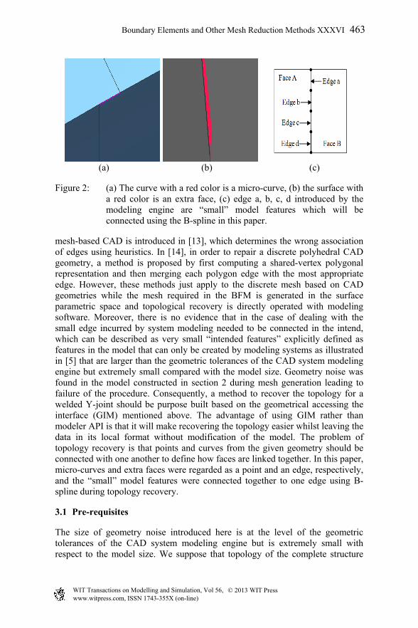
Geometry is a crucial constituent part of mesh generation or other simulation techniques based on discretization and as a bottleneck in the discretization process. A common interface for accessing geometry named GIM in this paper is developed. GIM is built from the CAD topology and geometric queries are passed through to the CAD system via direct access to APIs. Further, the method of topology recovery and geometry noise removal of welded tubular Y-joint is described based on this interface that can process the data more easily. For a more detailed discussion of these entities, see [10]. Since the setting tolerance of CAD geometric modeling system, CAD Boolean operations will sometimes introduce some geometrical noise entities, especially on large geometries made of complex assemblies, e.g. as shown in Fig. 2, micro-curves [11], silver, extra faces, “small” model feature [5], etc., which are not always directly suitable for surface mesh generation and even volume mesh generation because they can prevent a consistent boundary representation of the surface assembly from being built straightaway. It turns to be a problem of parametric meshing methods as AFT for generating a conforming surface mesh [12]. Modeling engines may also introduce many numbers of faces into the model to maintain that the model is valid and CAD models may contain geometric features that are important for design but are irrelevant for the simulation to be performed [5]. Thus, since the early 90s, many researchers have focused their efforts on methods for topology recovery. Most methods concentrate on recovering topology during translation involved between different CAD systems. An approach for recovering the topology of a
462 Boundary Elements and Other Mesh Reduction Methods XXXVI
Figure 2: (a) The curve with a red color is a micro-curve, (b) the surface with a red color is an extra face, (c) edge a, b, c, d introduced by the modeling engine are “small” model features which will be connected using the B-spline in this paper.
mesh-based CAD is introduced in [13], which determines the wrong association of edges using heuristics. In [14], in order to repair a discrete polyhedral CAD geometry, a method is proposed by first computing a shared-vertex polygonal representation and then merging each polygon edge with the most appropriate edge. However, these methods just apply to the discrete mesh based on CAD geometries while the mesh required in the BFM is generated in the surface parametric space and topological recovery is directly operated with modeling software. Moreover, there is no evidence that in the case of dealing with the small edge incurred by system modeling needed to be connected in the intend, which can be described as very small “intended features” explicitly defined as features in the model that can only be created by modeling systems as illustrated in [5] that are larger than the geometric tolerances of the CAD system modeling engine but extremely small compared with the model size. Geometry noise was found in the model constructed in section 2 during mesh generation leading to failure of the procedure. Consequently, a method to recover the topology for a welded Y-joint should be purpose built based on the geometrical accessing the interface (GIM) mentioned above. The advantage of using GIM rather than modeler API is that it will make recovering the topology easier whilst leaving the data in its local format without modification of the model. The problem of topology recovery is that points and curves from the given geometry should be connected with one another to define how faces are linked together. In this paper, micro-curves and extra faces were regarded as a point and an edge, respectively, and the “small” model features were connected together to one edge using B-spline during topology recovery.
3.1 Pre-requisites
The size of geometry noise introduced here is at the level of the geometric tolerances of the CAD system modeling engine but is extremely small with respect to the model size. We suppose that topology of the complete structure
Boundary Elements and Other Mesh Reduction Methods XXXVI 463
has already been obtained from the output geometry of the CAD system by directly accessing modeler API. We focus on how to reconstruct the topology from the developed method. In the algorithm, the tolerance is the only parameter the user can optionally tune. It defines the size of geometry noise the user wants to operate in the method and it will be set with the default value obtained from accessing the modeling system. In order to simplify notation, we use the term “curve” to take the place of “edge”.
3.2 The detail of recovery topology
The topology repairing procedure can be divided into the following four steps and the detailed algorithm is described in pseudo-code format. First, it is necessary to discretize the curves and the discretization method used in this paper comes from [15], because a large part of the algorithm is based on the evaluation of proximity between geometrical entities. In addition, it is easy to enumerate close curves in the space because the global topology has been preserved in GIM before that could achieve the method efficiently. Second, detecting geometry noise with some criteria used for processing the tiny features is built while the mapping of geometry noise associated with actual recovery entities is established. Finally, a conforming boundary representation of the surface is described. Definition 1: For a curve c, let )c(F
( c)F
be the set of faces f such that fc , )(cl be the length
of the curve and let )(cV be the set of vertices v such that cv .
The distance between 2 curves 1c and 2c is
)},(max),,(max{max),( 1221 21cbdcadccd cbca
Definition 2:
For 2 curves 1c and 2c , we define the proposition ),( 21 ccDcurve as
),( 21 ccd .
For a curve c , we define the proposition )(cLcurve as )(cl .
For a curve c , traverse in the current loop, forwards or backwards, to find the
curve 0c that has the same vertex with c . If curve c satisfies 0(c) ( )F F c
and the smooth
condition is defined as )(cSB , B-spline curve will be constructed to simulate all
curves that meet the condition, i.e. using a new creation of a B-spline curve to connect all original curves that satisfy the condition above. The condition
)()( 0cFcF will ensure that the current connected curves are geometrically
consistent curves on the topology while the smooth condition prevents error operation from irrelevant curves. In this paper, the relationship of two extremities of micro-curves required processing and the relationship of curves on
464 Boundary Elements and Other Mesh Reduction Methods XXXVI
the micro-surface will be built using the Standard library, named vtxMap and edgeMap, respectively. The reader should note that related topological data need to be updated regularly, such as the connection relationship among face, edge and vertex. In order to simplify the algorithm, these detailed operations will be omitted.
Detecting geometry noise Algorithm
vtxMap=edgeMap=NULL; step1: for each face f in the GIM do for each loop lp in the face do
if ( ),( 21 ccDcurve )
build the relationship of curves and restore in edgeMap; end end step2: for each curve in the model do
if ( )(cLcurve )
build the relationship of vertices and restore in vtxMap; end end
Recovery topology Algorithm in GIM
for each face f in the GIM do for each loop lp in the face do for each edge in the loop do according to step1, update )(cF
end end for each loop lp in the face do for each edge c in the loop do
for each edge 0c in the loop do
if ( )(cSB )
modeling a new edge using B-spline with removing the collapsing edge, reset )(cV and GIM.
end end if ( edgeMapc ) reset GIM
if ( vtxMap)(cV ) update )(cV
else creating a new point end end end
end
Boundary Elements and Other Mesh Reduction Methods XXXVI 465
The reader may notice that at the end of the procedure, the GIM acquires a consistent topology which could be used for further application, such as the mesh generation procedure.
4 Mesh generation examples
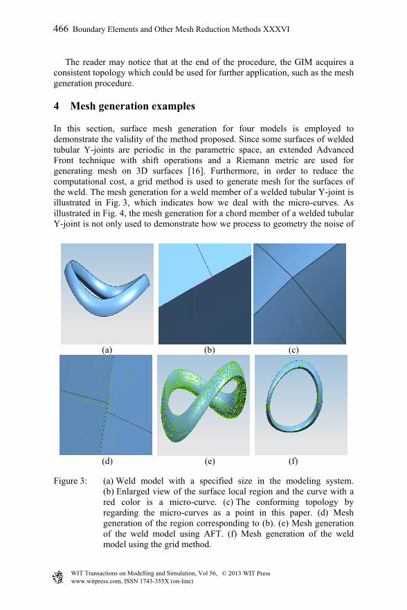
In this section, surface mesh generation for four models is employed to demonstrate the validity of the method proposed. Since some surfaces of welded tubular Y-joints are periodic in the parametric space, an extended Advanced Front technique with shift operations and a Riemann metric are used for generating mesh on 3D surfaces [16]. Furthermore, in order to reduce the computational cost, a grid method is used to generate mesh for the surfaces of the weld. The mesh generation for a weld member of a welded tubular Y-joint is illustrated in Fig. 3, which indicates how we deal with the micro-curves. As illustrated in Fig. 4, the mesh generation for a chord member of a welded tubular Y-joint is not only used to demonstrate how we process to geometry the noise of
(a) (b) (c)
(d) (e) (f)
Figure 3: (a) Weld model with a specified size in the modeling system. (b) Enlarged view of the surface local region and the curve with a red color is a micro-curve. (c) The conforming topology by regarding the micro-curves as a point in this paper. (d) Mesh generation of the region corresponding to (b). (e) Mesh generation of the weld model using AFT. (f) Mesh generation of the weld model using the grid method.
466 Boundary Elements and Other Mesh Reduction Methods XXXVI
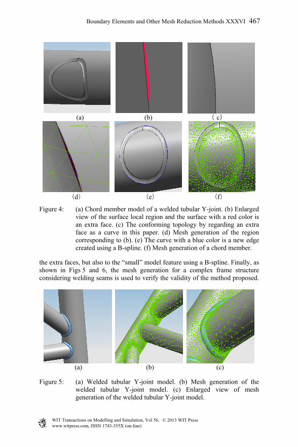
Figure 4: (a) Chord member model of a welded tubular Y-joint. (b) Enlarged view of the surface local region and the surface with a red color is an extra face. (c) The conforming topology by regarding an extra face as a curve in this paper. (d) Mesh generation of the region corresponding to (b). (e) The curve with a blue color is a new edge created using a B-spline. (f) Mesh generation of a chord member.
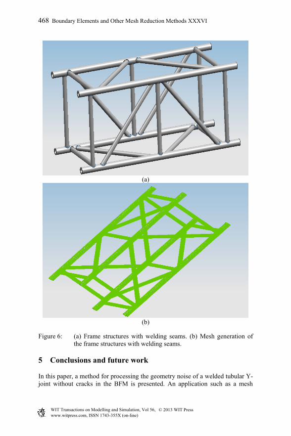
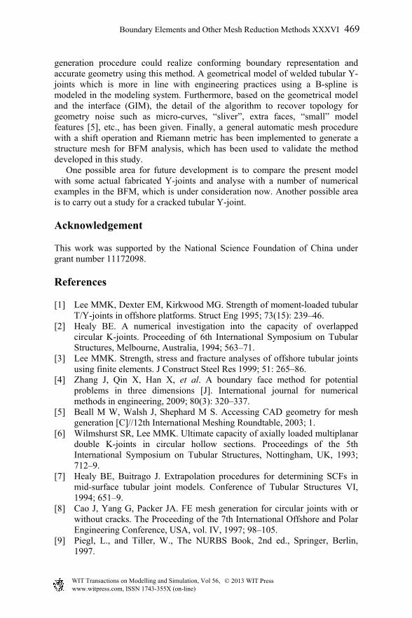
the extra faces, but also to the “small” model feature using a B-spline. Finally, as shown in Figs 5 and 6, the mesh generation for a complex frame structure considering welding seams is used to verify the validity of the method proposed.
(a) (b) (c)
Figure 5: (a) Welded tubular Y-joint model. (b) Mesh generation of the welded tubular Y-joint model. (c) Enlarged view of mesh generation of the welded tubular Y-joint model.
Boundary Elements and Other Mesh Reduction Methods XXXVI 467
Figure 6: (a) Frame structures with welding seams. (b) Mesh generation of the frame structures with welding seams.
5 Conclusions and future work
In this paper, a method for processing the geometry noise of a welded tubular Y-joint without cracks in the BFM is presented. An application such as a mesh
468 Boundary Elements and Other Mesh Reduction Methods XXXVI
generation procedure could realize conforming boundary representation and accurate geometry using this method. A geometrical model of welded tubular Y-joints which is more in line with engineering practices using a B-spline is modeled in the modeling system. Furthermore, based on the geometrical model and the interface (GIM), the detail of the algorithm to recover topology for geometry noise such as micro-curves, “sliver”, extra faces, “small” model features [5], etc., has been given. Finally, a general automatic mesh procedure with a shift operation and Riemann metric has been implemented to generate a structure mesh for BFM analysis, which has been used to validate the method developed in this study. One possible area for future development is to compare the present model with some actual fabricated Y-joints and analyse with a number of numerical examples in the BFM, which is under consideration now. Another possible area is to carry out a study for a cracked tubular Y-joint.
Acknowledgement
This work was supported by the National Science Foundation of China under grant number 11172098.
References
[1] Lee MMK, Dexter EM, Kirkwood MG. Strength of moment-loaded tubular T/Y-joints in offshore platforms. Struct Eng 1995; 73(15): 239–46.
[2] Healy BE. A numerical investigation into the capacity of overlapped circular K-joints. Proceeding of 6th International Symposium on Tubular Structures, Melbourne, Australia, 1994; 563–71.
[3] Lee MMK. Strength, stress and fracture analyses of offshore tubular joints using finite elements. J Construct Steel Res 1999; 51: 265–86.
[4] Zhang J, Qin X, Han X, et al. A boundary face method for potential problems in three dimensions [J]. International journal for numerical methods in engineering, 2009; 80(3): 320–337.
[5] Beall M W, Walsh J, Shephard M S. Accessing CAD geometry for mesh generation [C]//12th International Meshing Roundtable, 2003; 1.
[6] Wilmshurst SR, Lee MMK. Ultimate capacity of axially loaded multiplanar double K-joints in circular hollow sections. Proceedings of the 5th International Symposium on Tubular Structures, Nottingham, UK, 1993; 712–9.
[7] Healy BE, Buitrago J. Extrapolation procedures for determining SCFs in mid-surface tubular joint models. Conference of Tubular Structures VI, 1994; 651–9.
[8] Cao J, Yang G, Packer JA. FE mesh generation for circular joints with or without cracks. The Proceeding of the 7th International Offshore and Polar Engineering Conference, USA, vol. IV, 1997; 98–105.
[9] Piegl, L., and Tiller, W., The NURBS Book, 2nd ed., Springer, Berlin, 1997.
Boundary Elements and Other Mesh Reduction Methods XXXVI 469
[10] Timothy J. Tautges, “The Common Geometry Module (CGM)”, Sandia National Laboratories report, in preparation.
[11] Alleaume A. Automatic Non-manifold Topology Recovery and Geometry Noise Removal [M]//Proceedings of the 18th International Meshing Roundtable. Springer Berlin Heidelberg, 2009; 267–279.
[12] Laug P, Borouchaki H. BLSURF-mesh generator for composite parametric surfaces. INRIA Technical Report RT-0235 (1999).
[13] Weihe, K., Willhalm, T.: Reconstructing the Topology of a CAD Model: A Discrete Approach. In: Burkard, R.E., Woeginger, G.J. (eds.) ESA 1997. LNCS, vol. 1284, pp. 500–513. Springer, Heidelberg (1997).
[14] Barequet, G., Kumar, S.: Repairing CAD models. In: Proceedings of the 8th conference on Visualization (VIS 1997), 1997; 363–370.
[15] Cuilliere J C. A direct method for the automatic discretization of 3D parametric curves [J]. Computer-Aided Design, 1997; 29(9): 639–647.
[16] Guan Z, Shan J, Zheng Y, et al. An extended advancing front technique for closed surfaces mesh generation [J]. International journal for numerical methods in engineering, 2008; 74(4): 642–667.
470 Boundary Elements and Other Mesh Reduction Methods XXXVI