Page 1
ii
TREATMENT OF INDUSTRIAL DETERGENT WASTEWATER VIA
MEMBRANE SEPARATION
BAHRUN BIN MOHD SHAKIR
a thesis submitted in fulfillment
of the requirements for the award of the degree of
bachelor of chemical engineering
Faculty of Chemical & Natural Resources Engineering
Universiti Malaysia Pahang
APRIL 2010
Page 2
v
ABSTRACT
This thesis presents the experimental study of the potential of Nanofiltration
membrane in treating industrial detergent wastewater that contains high Linear
Alkylbenzene Sulfonate (LAS). LAS is the most common synthetic anionic surfactant
used in domestic and industrial detergents and can cause significant environmental
problems. This study was focused on treated wastewater sample from FPG Oleochemical
Sdb Bhd based on decreasing the parameters so it can comply with the regulation of
Environment Quality Act (EQA), 1974 before it can release to discharge. LAS, Chemical
Oxygen Demand (COD), Total Organic Carbon (TOC), Total Suspended Solid (TSS)
and Turbidity were used as a parameters used in this study. The Polyamide
Nanofiltration membrane performance was characterized by varying the Trans
Membrane Pressure (TMP) 3, 4, 5 and 6 bars. The results showed that the optimum
operating condition of the Nanofiltration membrane was achieved at TMP 6 bar. The
removal percentage of the parameters is high which is more than 88%. However, only
the Turbidity and TSS has achieved the EQA regulation. It is concluded that the
wastewater from the production of Dynamo in FPG Oleochemical Sdn Bhd can be fully
treated by using Nanofiltration membrane in addition some pre treatment or further
treatment.
Page 3
vi
ABSTRAK
Tesis ini menyajikan kajian eksperimental potensi Nanofiltrasi membran dalam
mengolah sisa cair industri yang mengandungi detergen Linear Alkylbenzene Sulfonate
(LAS). LAS adalah surfaktan anionik sintetik yang paling biasa digunakan dalam
industri detergen dan domestik dan ia boleh menyebabkan masalah persekitaran yang
signifikan. Penelitian ini difokuskan pada perawatan sampel air sisa dari FPG
Oleochemical SDB Bhd berdasarkan penurunan parameter sehingga dapat memenuhi
syarat-syarat Environmental Quality Act (EQA), 1974 sebelum dilepaskan. LAS,
Chemical Oksigen Demand (COD), Total Organic Carbon (TOC), Total Suspended
Solid (TSS) dan Turbidity dijadikan sebagai parameter yang digunakan dalam kajian ini.
Prestasi Polyamide Nanofiltrasi membran diuji dengan memvariasikan Trans Membran
Pressure (TMP) 3, 4, 5 dan 6 Bar. Keputusan kajian menunjukkan bahawa keadaan
operasi optimum membran Nanofiltrasi ialah pada TMP 6 Bar. Peratusan penghapusan
parameter adalah tinggi iaitu melebihi 88%. Namun, hanya Turbidity dan TSS
mencapai kehendak peraturan EQA. Dapat disimpulkan bahawa air sisa hasil daripada
pengeluaran Dynamo di FPG Oleochemical Sdn Bhd boleh sepenuhnya dirawat dengan
menggunakan membran Nanofiltrasi denagan kombinasi beberapa rawatan pra atau
rawatan tambahan.
Page 4
vii
TABLE OF CONTENT
CHAPTER TOPICS PAGE
TITLE i
STATEMENT ii
DECLARATION iii
ACKNOWLEDGEMENTS iv
ABSTRACT v
ABSTRAK vi
TABLE OF CONTENT vii
LIST OF FIGURES xi
LIST OF TABLES xii
1 INTRODUCTION
1.1 Background 1
1.2 Problem Statement 3
1.3 Objective 3
1.4 Scope of study 3
1.5 Outline of This Thesis 4
2 LITERATURE REVIEW
2.1 Surfactant 5
2.2 Linear alkylbenzene sulfonate 6
2.3 Membrane 6
Page 5
viii
2.3.1 Membrane Separation 7
2.3.2 Pressure Driven Membrane 8
2.3.3 Electrically Driven Membrane 12
2.4 Cross Flow System 12
2.5 Advantages and Disadvantages of Membrane 14
2.6 Parameters 15
2.6.1 Anionic Surfactant 15
2.6.2 Chemical Oxygen Demand (COD) 15
2.6.3 Turbidity 16
2.6.4 Total Organic Carbon (TOC) 16
2.6.5 Total Suspended Solid (TSS) 17
2.7 Water Quality Index 17
2.8 Linear Alkylbenzene Sulfonate (LAS) Treatment 20
2.9 Chemical Oxygen Demand and Suspended Solid
Treatment
21
2.10 Turbidity and Total Organic Carbon Treatment 21
2.11 Conclusion 22
3 EXPERIMENTAL SETUP
3.1 Introduction 24
3.2 Nanofiltration Membrane Experimental Setup 25
3.3 Nanofiltration Membrane Treatment Operating
Procedure
27
4 ANALYTICAL MATERIALS AND METHODS
4.1 Introduction 28
4.2 Material used for Nanofiltration Process and
Analysis
29
4.3 Method of Characterizations 29
4.3.1 Chemical Oxygen Demand (COD) 29
Page 6
ix
4.3.2 Linear Alkylbenzene Sulfonate (LAS) 30
4.3.3 Total Suspended Solid (TSS) 30
4.3.4 Total Organic Carbon (TOC) 31
4.3.5 Turbidity 32
5 RESULTS & DISCUSSION
5.1 Introduction 32
5.2 Comparison between the Treated and Untreated
Sample
32
5.3 Effect of Trans Membrane Pressure (TMP) Drop 34
5.3.1 Effect of TMP on COD 34
5.3.2 Effect of TMP on LAS 35
5.3.3 5.3.3 Effect of TMP on TOC 36
5.3.4 Effect of TMP on TSS 37
5.3.5 Effect of TMP on Turbidity 38
5.4 Summary of Parameters Removal Percentages 39
5.5 Comparison between Treated Samples with EQA 40
6 CONCLUSION & RECOMMENDATION
5.1 Conclusion 48
5.2 Recommendation 49
REFERENCES 51
Page 7
x
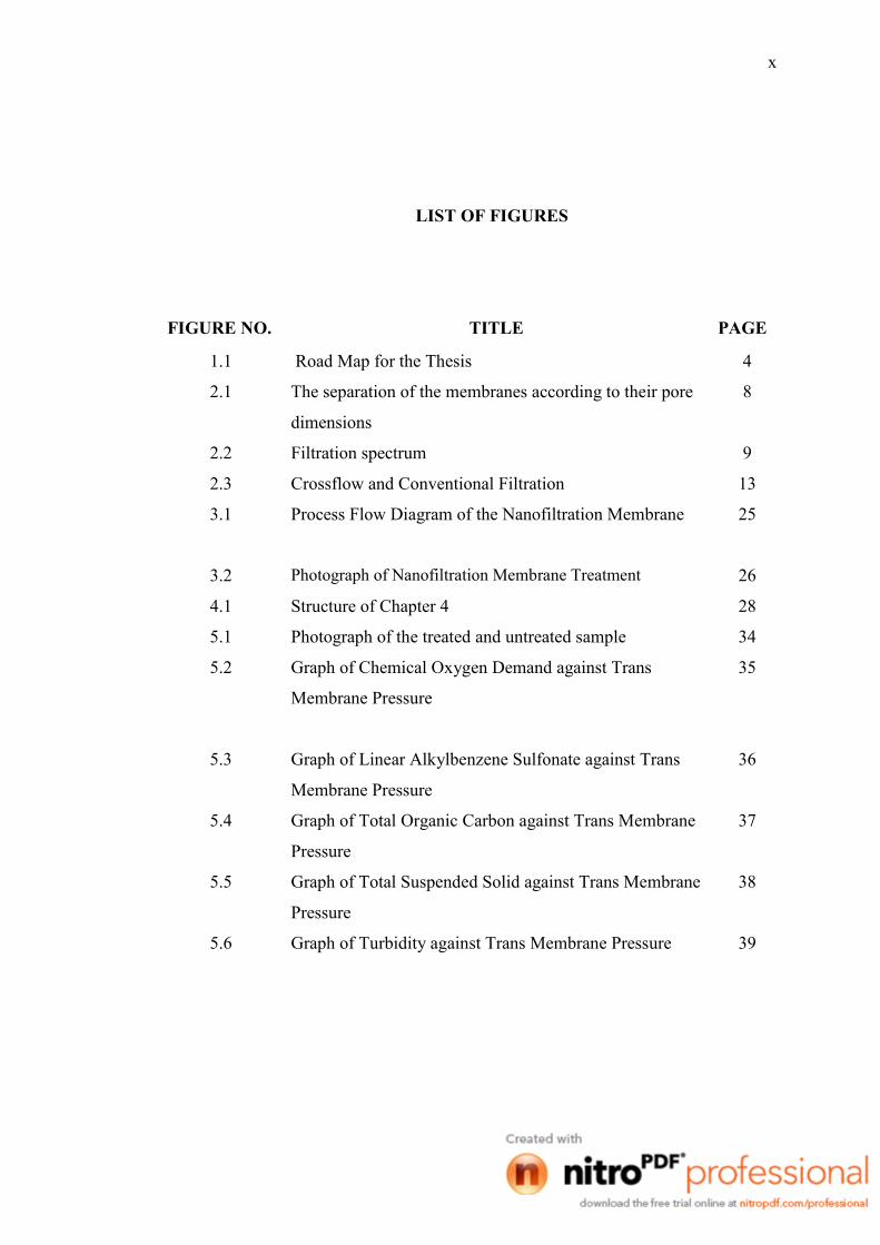
LIST OF FIGURES
FIGURE NO. TITLE PAGE
1.1 Road Map for the Thesis 4
2.1 The separation of the membranes according to their pore
dimensions
8
2.2 Filtration spectrum 9
2.3 Crossflow and Conventional Filtration 13
3.1 Process Flow Diagram of the Nanofiltration Membrane
25
3.2 Photograph of Nanofiltration Membrane Treatment 26
4.1 Structure of Chapter 4 28
5.1 Photograph of the treated and untreated sample 34
5.2 Graph of Chemical Oxygen Demand against Trans
Membrane Pressure
35
5.3 Graph of Linear Alkylbenzene Sulfonate against Trans
Membrane Pressure
36
5.4 Graph of Total Organic Carbon against Trans Membrane
Pressure
37
5.5 Graph of Total Suspended Solid against Trans Membrane
Pressure
38
5.6 Graph of Turbidity against Trans Membrane Pressure 39
Page 8
xi
LIST OF TABLES
TABLE NO TITLE PAGE
1.1 Characteristics of Nanofiltration membrane used 2
2.1 Comparison of Membrane Features 7
2.2 Comparison of Pressure driven Membrane Systems 11
2.3 Receiving Water Quality from Interim National Water
Quality Standards (INWQS) for Malaysia
18
2.4 Environmental Quality (Sewage and Industrial
Effluents), Regulations 1979. Maximum Effluent
Parameter Limits Standards A and B.
19
4.1 List of Material 29
5.1 Parameters Removal Percentage 40
5.2 Comparison with EQA 1974 41
Page 9
UUNNIIVVEERRSSIITTII MMAALLAAYYSSIIAA PPAAHHAANNGG PSZ 19:16
(Pind. 1/97)
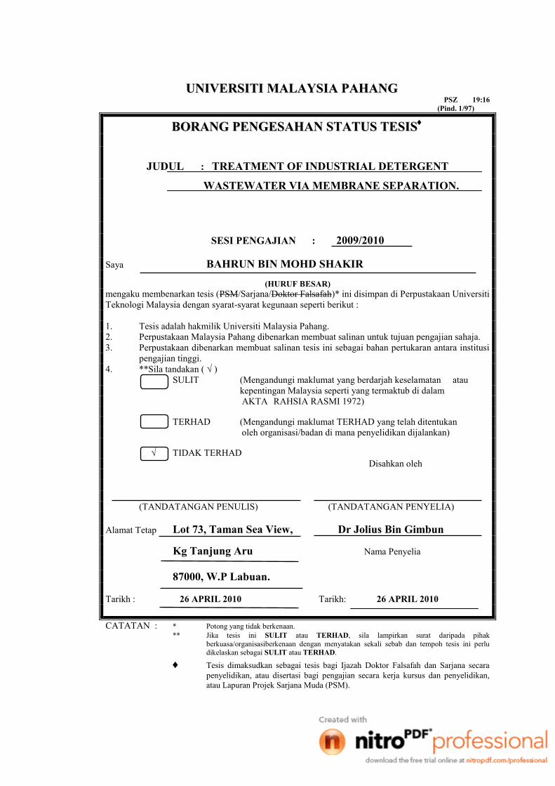
BBOORRAANNGG PPEENNGGEESSAAHHAANN SSTTAATTUUSS TTEESSIISS
JUDUL : TREATMENT OF INDUSTRIAL DETERGENT
WASTEWATER VIA MEMBRANE SEPARATION.
SESI PENGAJIAN : 2009/2010
Saya BAHRUN BIN MOHD SHAKIR
(HURUF BESAR) mengaku membenarkan tesis (PSM/Sarjana/Doktor Falsafah)* ini disimpan di Perpustakaan Universiti
Teknologi Malaysia dengan syarat-syarat kegunaan seperti berikut :
1. Tesis adalah hakmilik Universiti Malaysia Pahang.
2. Perpustakaan Malaysia Pahang dibenarkan membuat salinan untuk tujuan pengajian sahaja.
3. Perpustakaan dibenarkan membuat salinan tesis ini sebagai bahan pertukaran antara institusi
pengajian tinggi.
4. **Sila tandakan ( √ )
SULIT (Mengandungi maklumat yang berdarjah keselamatan atau
kepentingan Malaysia seperti yang termaktub di dalam
AKTA RAHSIA RASMI 1972)
TERHAD (Mengandungi maklumat TERHAD yang telah ditentukan
oleh organisasi/badan di mana penyelidikan dijalankan)
√ TIDAK TERHAD
Disahkan oleh
(TANDATANGAN PENULIS) (TANDATANGAN PENYELIA)
Alamat Tetap Lot 73, Taman Sea View, Dr Jolius Bin Gimbun
Kg Tanjung Aru Nama Penyelia
87000, W.P Labuan.
Tarikh : 26 APRIL 2010 Tarikh: 26 APRIL 2010
CATATAN : * Potong yang tidak berkenaan.
** Jika tesis ini SULIT atau TERHAD, sila lampirkan surat daripada pihak
berkuasa/organisasiberkenaan dengan menyatakan sekali sebab dan tempoh tesis ini perlu dikelaskan sebagai SULIT atau TERHAD.
Tesis dimaksudkan sebagai tesis bagi Ijazah Doktor Falsafah dan Sarjana secara
penyelidikan, atau disertasi bagi pengajian secara kerja kursus dan penyelidikan,
atau Lapuran Projek Sarjana Muda (PSM).
Page 10
1
CHAPTER 1
INTRODUCTION
1.1 Background
Increased water consumption for both industrial and domestic purposes has led to
a shortage of good quality surface and groundwater resources and to an increase in the
costs of water and wastewater treatment. As a consequence of this shortage it would be
prudent for any rational water management authority to secure the purest water sources
for direct human consumption and to encourage the reuse of processed water for
industrial applications (Rozi et al., 1999). Environmental risks associated with detergent
manufacture, its use and disposal are of great concern due to the relative toxicity of
detergent products and its core ingredients (surfactants) on aquatic life (Lin et al., 1999).
Surfactants have also been widely used in textile, fiber, food, paints, polymers, plant
protection, cosmetics, pharmaceuticals as well as mining, pulp and paper industries (Lin
et al., 1999). Among wide range of surfactant types, linear alkylbenzene sulfonate (LAS)
is the most common synthetic anionic surfactant used in domestic and industrial
detergents. The majority of detergent products reach the environment with domestic and
industrial wastewater. The high and varied pollution loads of these effluents are mainly
due to the residual products in the reactor, which have to be washed away in order to use
the same facility for the manufacture of other products. Detergent solution can cause
significant environmental problems because detergent product and its ingredients can be
Page 11
2
relatively toxic to aquatic life. That’s why the detergent solution needs to be treated
before release to discharge.
In this study, the wastewater sample is the excess solution from the batch process
on production of liquid detergent Dynamo. Basically, this detergent solution contains
very high LAS. This study was focused on treated this wastewater sample based on
decreasing the parameters so it can comply with the regulation of environment quality
act, 1974 before it can release to discharge. This wastewater sample is treated using
membrane separation process. The membrane use is Turbular Nanofiltration membrane.
This method will reduce the anionic surfactant and also the Chemical Oxygen Demand
(COD) in the detergent solution. The LAS is the main parameter in this study. Besides
the LAS and COD, the Nanofiltration membrane also can remove the viruses, bacteria
and the suspended solid.
The type of Turbular Nanofiltration used in this study is Polyamide membrane
with dimension 4 inch D x 4ft L. This process will reduce the COD contain in the
solution and also can remove the heavy metal and solid that a common use in wastewater
treatment. Table 1.1 below shows the detail characteristics of Nanofiltration membrane
use.
Table 1.1: Characteristics of Nanofiltration membrane used
Make PCI – Memtech (UK)
Type AFC 40 Membrane
Material Polyamide
Housing SS 316
Max pH range 1.5 – 9.5
Max Pressure 60 bar
Retention character 60% CaCl2
Dimension 4‖ D x 4ft L
Page 12
3
1.2 Problem Statement
The wastes that have been produced need to be treated before discharge to
prevent our environmental from pollution. Untreated waste may damage our
environment and also present serious hazard to human and other living thing. The
wastewater in this study is the linear alkylbenzene sulfonate (LAS), commonly used in
the formulation of detergents and present in industrial wastewaters. The detergent
solutions that contain high LAS are harmful to environment if they are not fully treated
before discharge. To solve this problem, the wastewater needs to be treated before it is
allowed for release to the drainage system. This work aim to evaluate the performance of
Nanofiltration membrane for treating LAS contaminated wastewater from FPG
Oleochmical Sdn Bhd.
1.3 Objective
The objective of this project is to evaluate the effectiveness of Nanofiltration
membrane in treating the LAS contaminated wastewater from FPG Oleochemical Sdn
Bhd.
1.4 Scope of Study
To achieve the objective of this project, the treated and untreated wastewater
needs to be characterized. Besides that, the membrane performance is also studied by
analyzing it surfactant retention and the permeate flux. The factor that affects the
surfactant retention and permeates flux is the Trans membrane pressure (TMP), the
Page 13
4
crossfow velocity and the surfactant concentration. Therefore, optimum operating
condition of the membrane may be obtained by varying the TMP.
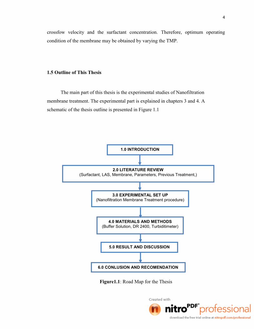
1.5 Outline of This Thesis
The main part of this thesis is the experimental studies of Nanofiltration
membrane treatment. The experimental part is explained in chapters 3 and 4. A
schematic of the thesis outline is presented in Figure 1.1
Figure1.1: Road Map for the Thesis
1.0 INTRODUCTION
2.0 LITERATURE REVIEW (Surfactant, LAS, Membrane, Parameters, Previous Treatment,)
3.0 EXPERIMENTAL SET UP (Nanofiltration Membrane Treatment procedure)
4.0 MATERIALS AND METHODS (Buffer Solution, DR 2400, Turbiditimeter)
5.0 RESULT AND DISCUSSION
6.0 CONLUSION AND RECOMENDATION
Page 14
5
CHAPTER 2
LITERATURE REVIEW
2.1 What is surfactant?
Surfactant is an abbreviation for surface active agent, which literally means
active at a surface (Porter, 1994). Surface active agents are compounds having a
hydrophobic and a hydrophilic group (Falbe, 1987) and, hence, they show a tendency to
adsorb at liquid/solid, liquid/liquid and air/liquid interfaces. They are mainly used in
aqueous solutions and are classified according its hydrophilic group in anionic, cationic,
nonionic, and amphoteric surfactants. Due to their chemical structure, surfactants are
strongly adsorbed at an interface or they form colloid aggregates in solution at very low
concentrations, lowering the interfacial tension. Surfactants have found many industrial
applications, such as detergency, wetting, cleaning, emulsification, foam control and
lubricity in industrial systems (Chen et al., 1992). Some novel separation techniques
using biodegradable surfactants (such as colloid-enhanced ultrafiltration, admicellar
chromatography and surfactant-enhanced carbon regeneration) are also used in
wastewater cleanup and groundwater remediation (Canselier et al., 1995). The
worldwide surfactant consumption was of the order of 10.4M tons in year 2000 (Crabb
et al 1999) and consequently large amounts are discharged into the environment.
Therefore, the treatment of effluent streams containing surfactants is an important issue,
either for environmental or economic reasons.
Page 15
6
2.2 Linear alkylbenzene sulfonate
LAS are produced by sulfonation of linear alkylbenzene with sulfur trioxide.
LAS is a mixture of closely related isomers and homologues, each containing an
aromatic ring sulfonated at the para position and attached to a linear alkyl chain with the
length which varies between C10 and C14 (Dealmedia et al., 1994). Detergents usually
contain 5 - 25 % of LAS. From the environmental point of view, it is the major
anthropogenic source of organic compounds in primary sludge of the municipal
wastewater treatment plants. It can be adsorbed onto suspended solids ranging from 30
to 70 % and, hence, escaping aerobic treatment (www.heraproject.com). It has also been
identified in surface water supplies in the concentrations lower than 1 μg dm-3
(Berna et
al., 1989), and in the drinking water with the concentrations of 0.001 - 0.008 mg dm-3
(Delmedia et al., 1994). It has been reported that LAS at higher concentrations, between
20 and 50 mg dm-3
, such as in detergent manufacturing wastewaters, is not
biodegradable (Tabrizi et al., 2006). It is implied that some of chemical processes need
to be used to degrade aqueous LAS.
2.3 Membrane
Membrane systems have been used in specialized applications for more than 30
years, largely for water treatment, including desalination of seawater and brackish water.
With technical advances and corresponding cost reductions, membrane systems are now
capable of decontaminating nonsaline waters (including treated wastewaters) in single
step processes at competitive costs. The demand for membranes in the water and
wastewater industry is projected to increase at a 9% annual rate and reach $540 million
by year 2000. About two-thirds of the market will be for water, and one-third for
Page 16
7
wastewater. Membrane technologies are receiving special recognition as alternatives to
conventional water treatment and as a means of polishing treated wastewater effluent for
reuse applications. Membrane technologies are energy intensive.
New membrane technologies feature the use of low pressure systems that significantly
reduce energy use and operation and maintenance costs. Membranes are commonly used
for the removal of dissolved solids, color, and hardness in drinking water.
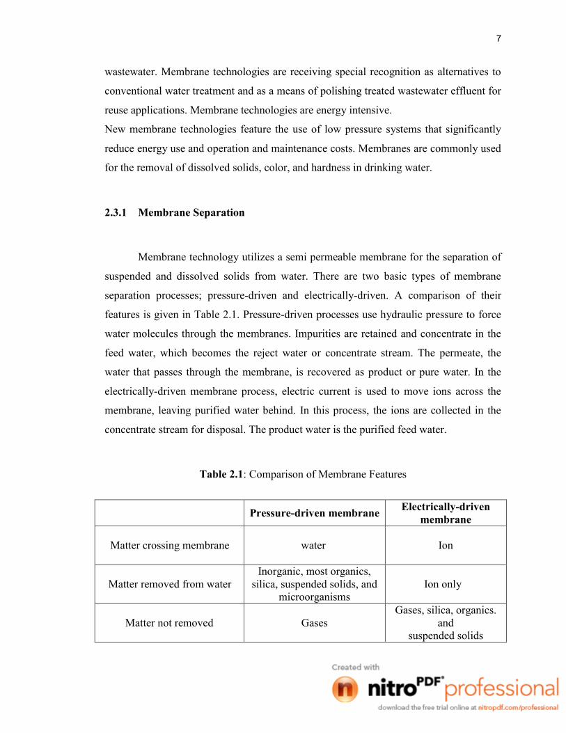
2.3.1 Membrane Separation
Membrane technology utilizes a semi permeable membrane for the separation of
suspended and dissolved solids from water. There are two basic types of membrane
separation processes; pressure-driven and electrically-driven. A comparison of their
features is given in Table 2.1. Pressure-driven processes use hydraulic pressure to force
water molecules through the membranes. Impurities are retained and concentrate in the
feed water, which becomes the reject water or concentrate stream. The permeate, the
water that passes through the membrane, is recovered as product or pure water. In the
electrically-driven membrane process, electric current is used to move ions across the
membrane, leaving purified water behind. In this process, the ions are collected in the
concentrate stream for disposal. The product water is the purified feed water.
Table 2.1: Comparison of Membrane Features
Pressure-driven membrane
Electrically-driven
membrane
Matter crossing membrane
water
Ion
Matter removed from water
Inorganic, most organics,
silica, suspended solids, and
microorganisms
Ion only
Matter not removed
Gases
Gases, silica, organics.
and
suspended solids
Page 17
8
2.3.2 Pressure Driven Membrane
Membranes are made of several materials in several configurations and they can
be thought as a kind of filter under certain pressure. The most important duty of a
membrane is to act as a selective barrier (Cheryan. 1998). Membrane filters are usually
used to separate the compounds of dimensions smaller than 10 micrometer from the
liquor. The flow on the membrane surface is in two directions; parallel to the membrane
axis and in a radial direction (cross-flow). Particles having greater dimensions than the
membrane pores are held-back on the surface of the membrane and carried out by the
parallel flow and collected as concentrate. Particles having smaller molecular sizes than
the membrane pores pass through the membrane with the cross-flow and collected as
permeate. Consequently, the molecules in the liquor are separated physically according
to their molecular dimensions (Dickenson, 1997). The most popular membrane
processes are microfiltration (MF), ultrafiltration (UF), nanofiltration (NF) and reverse
osmosis (RO) which separates the compounds in the liquor according to molecular
dimensions under hydrostatic pressure. Figure 2.1 illustrates the separating action
according to the pore size.
Figure 2.1: The separation of the membranes according to their pore dimensions
(Cheryan, 1998)
Page 18
9
The range of sizes of selected constituents in water and wastewater and the
performance capabilities of the different membranes are illustrated in Figure 2.2. MF
and UF often serve to remove large organic molecules, large colloidal particles, and
many microorganisms (see Table 2.2). MF performs as a porous barrier to reduce
turbidity and some types of colloidal suspensions. UF offers higher removals than MF,
but operates at higher pressures. In wastewater reclamation, MF UF might provide a
suitable level of treatment. In drinking-water treatment, MF or UF might be used in
tandem with NF or RO to remove coarser material so that fouling of the less permeable
membranes is minimized.
Figure 2.2: Filtration spectrum
Page 19
10
a. Microfiltration Membrane
Microfiltration membranes remove all bacteria. Only part of the viral
contamination is caught up in the process, even though viruses are smaller than the pores
of a micro filtration membrane. This is because viruses can attach themselves to
bacterial biofilm. Micro filtration can be implemented in many different water treatment
processes when particles with a diameter greater than 0.1 mm need to be removed from a
liquid. Membranes with a pore size of 0.1 – 10 µm perform micro filtration.
(www.lenntech.com)
b. Ultrafiltration Membrane
Ultrafiltration or UF is a pressure driven membrane separation process that
separates particulate matter from soluble components in the carrier fluid (such as water).
UF membranes typically have a high removal capability for bacteria and most viruses,
colloids and silt (SDI). The smaller the nominal pore size, the higher the removal
capability. Most materials that are used in UF are polymeric and are naturally
hydrophobic. Common polymeric materials used in UF include: Polysulfone (PS),
Polyethersulfone (PES), Polypropylene (PP), or Polyvinylidenefluoride (PVDF).
Although these materials can be blended with hydrophilic agents, they can reduce the
membranes ability to be cleaned with high strength disinfectants such as hypochlorite
that impacts removal of bacterial growth.
c. Nanofiltration Membrane
Nanofiltration is a liquid separation membrane technology positioned between
reverse osmosis (RO) and ultrafiltration. While RO can remove the smallest of solute
molecules, in the range of 0.0001 micron in diameter and smaller, nanofiltration (NF)
Page 20
11
removes molecules in the 0.001 micron range. NF refers to a membrane process that
rejects solutes approximately 1 nanometer (10 angstroms) in size with molecular weights
above 200. Because they feature pore sizes larger than RO membranes, NF membranes
remove organic compounds and selected salts at lower pressures than RO systems. NF
essentially is a lower-pressure version of RO where the purity of product water is not as
critical as with pharmaceutical grade water, or the level of dissolved solids to be
removed is less than what typically is encountered in brackish water or seawater.
(www.wwdmag.com)
d. Reverse Osmosis Membrane
Reverse osmosis is a filtration process that is often used for water. It works by
using pressure to force a solution through a membrane, retaining the solute on one side
and allowing the pure solvent to pass to the other side. Liquid phase pressure-driven
separation process in which applied transmembrane pressure causes selective movement
of solvent against its osmotic pressure difference (Koros et al., 1996). This is the reverse
of the normal osmosis process, which is the natural movement of solvent from an area of
low solute concentration, through a membrane, to an area of high solute concentration
when no external pressure is applied.
Table 2.2: Comparison of Pressure driven Membrane Systems
PARAMETERS
Membrane System
MF UF NF RO
Product particle
size, pm
0.008 to 2.0
0.005 to 0.2
0.001 to 0.01
0.0001to 0.001
Retained
compounds
Operating
Very small
suspended
particles, some
colloids, most
bacteria
Organics >l000
MW, pyrogens,
viruses, bacteria,
colloids
Organics > 300
MW, THM
Precursors, some
dissolved solid,
divalent >
monovalent
Ion, Organic >
100 MW
Page 21
12
Pressure, psi
1 to 15
10 to 100
80 to 125
125 to 1000
Maximum
temperature, "F
("C)
80 (27)
80 (27)
80 (27)
100 (38)
Recovery rate,
%
100
75
85
50-85
2.3.3 Electrically Driven Membrane
Electro dialysis reversal (EDR) is an improvement over the original electro
dialysis process. In EDR, the direct-current driving force is periodically reversed to
prevent scaling and fouling of the membrane surface. This innovation improves both the
efficiency and the operating life of membranes. Ion exchange membranes are the heart
of the process. Cation-selective and anion-selective membranes are alternately placed in
a membrane ―stack‖. Water flows between the membranes, and when direct current is
applied across the stack, positive Ions move toward the cathode and negative ions move
toward the anode. Due to the alternating membranes, salt is removed from every other
compartment and collected in intervening compartments. The salt-laden water is then
discharged as a brine concentrate; desalted water is discharged to the purified-water
collection system.
2.4 Cross Flow System
Crossflow filtration also known as tangential flow filtration (Millipore Technical
Library) is a type of filtration. Crossflow filtration is different from dead-end filtration in
which the feed is passed through a membrane or bed, the solids being trapped in the
filter and the filtrate being released at the other end. Cross-flow filtration gets its name
Page 22
13
because the majority of the feed flow travels tangentially across the surface of the filter,
rather than into the filter (Koros et al., 1996). The principle advantage of this is that the
filter cake (which can blind the filter) is substantially washed away during the filtration
process, increasing the length of time that a filter unit can be operational. It can be a
continuous process, unlike batch-wise dead-end filtration. This type of filtration is
typically selected for feeds containing a high proportion of small particle size solids
(where permeate is of most value) because solid material can quickly block (blind) the
filter surface with dead-end filtration. Industrial examples of this include the extraction
of soluble antibiotics from fermentation liquors.
In crossflow filtration, the feed is passed across the filter membrane
(tangentially) at positive pressure relative to the permeate side. A proportion of the
material which is smaller than the membrane pore size passes through the membrane as
permeate or filtrate; everything else is retained on the feed side of the membrane as
retentate. With crossflow filtration the tangential motion of the bulk of the fluid across
the membrane causes trapped particles on the filter surface to be rubbed off. This means
that a crossflow filter can operate continuously at relatively high solids loads without
blinding. Figure 2.3 show the flow of Crossflow and conventional Filtration.
Figure 2.3: Crossflow and Conventional Filtration
Page 23
14
2.5 Advantages and disadvantages of membrane
Advantages:
1. Membrane separation consistently separates a wide variety of emulsion,
surfactant, and chelating chemistries and various mixtures.
2. It requires no specific chemical knowledge.
3. Complex instrumentation is not required.
4. The method does not require constant attention.
5. The basic concept is simple to understand.
Disadvantages:
1. Membranes are expensive.
2. Certain solvents can quickly and permanently destroy the membrane.
3. Certain colloidal solids, especially graphite and residues from vibratory
deburring operations, can permanently foul the membrane surface.
4. The energy cost is higher than chemical treatment, although less than
evaporation.
5. Oil emulsions are not "chemically separated," so secondary oil recovery can
be difficult.
6. Synthetics are not effectively treated by this method.
Page 24
15
2.6 Parameters
2.6.1 Anionic Surfactant (Linear alkyl benzene sulfonate)
The LAS is the most widely used type of surfactant for laundering, dishwashing
liquids and shampoos because of its excellent cleaning properties and high sudsing
potential. The surfactant is particularly good at keeping the dirt away from fabrics, and
removing residues of fabric softener from fabrics. Anionic surfactants are particularly
effective at oily soil cleaning and oil/clay soil suspension. Still, they can react in the
wash water with the positively charged water hardness ions (calcium and magnesium),
which can lead to partial deactivation. The more calcium and magnesium molecules in
the water, the more the anionic surfactant system suffers from deactivation. To prevent
this, the anionic surfactants need help from other ingredients such as builders (Ca/Mg
sequestrants) and more detergent should be dosed in hard water. The most commonly
used anionic surfactants are alkyl sulphates, alkyl ethoxylate sulphates and soaps.
2.6.2 Chemical Oxygen Demand (COD)
The chemical oxygen demand is a measure of the oxidizability of a substance,
expressed as the equivalent amount in oxygen of an oxidizing reagent consumed by the
substance under fixed laboratory conditions. COD measurements are commonly made
on samples of waste waters or of natural waters contaminated by domestic or industrial
wastes. Chemical oxygen demand is measured as a standardized laboratory assay in
which a closed water sample is incubated with a strong chemical oxidant under specific
conditions of temperature and for a particular period of time.
A commonly used oxidant in COD assays is potassium dichromate (K2Cr2O7)
which is used in combination with boiling sulfuric acid (H2SO4). Because this chemical
oxidant is not specific to oxygen-consuming chemicals that are organic or inorganic,