45
Information & Technology Group Operational Technology STANDARD DESIGN DS 45-06 Treatment Plant Design VERSION 1 REVISON 0 May 2021
Information & Technology Group Operational Technology
STANDARD DESIGN DS 45-06
Treatment Plant Design
VERSION 1
REVISON 0
May 2021

Standard Design No. DS45-06 Treatment Plant Design
Uncontrolled if Printed Ver 1 Rev 0
Page 2 of 45
© Copyright Water Corporation 2021-2024
FOREWORD
Operational Technology Standard Designs are prepared in order to ensure that assets are delivered efficiently and
perform in a consistent manner. Having standard designs simplifies the delivery process considerably thereby
reducing costs and decreasing delivery times.
The Standard Design has been developed as a collaborative effort involving Water Corporation and industry
experts. Any deviation from this design must be justifiable and must be approved by the Head of Operational
Technology.
Users are invited to forward submissions for continuous improvement to the Principal SCADA Engineer who will
consider these for incorporation into future revisions.
Head of Operational Technology
This document is prepared without the assumption of a duty of care by the Water Corporation. The document is
not intended to be nor should it be relied on as a substitute for professional engineering design expertise or any
other professional advice.
It is the responsibility of the user to ensure they are using the current version of this document.
© Copyright – Water Corporation: This standard and software is copyright. With the exception of use permitted
by the Copyright Act 1968, no part may be reproduced without the written permission of the Water Corporation.

Standard Design No. DS45-06 Treatment Plant Design
Uncontrolled if Printed Ver 1 Rev 0
Page 3 of 45
© Copyright Water Corporation 2021-2024
DISCLAIMER
Water Corporation accepts no liability for any loss or damage that arises from anything in the
Standards/Specifications including any loss or damage that may arise due to the errors and omissions of any person.
Any person or entity which relies upon the Standards/Specifications from the Water Corporation website does so at
their own risk and without any right of recourse to the Water Corporation, including, but not limited to, using the
Standards/Specification for works other than for or on behalf of the Water Corporation.
The Water Corporation shall not be responsible, nor liable, to any person or entity for any loss or damage suffered
as a consequence of the unlawful use of, or reference to, the Standards/Specifications, including but not limited to
the use of any part of the Standards/Specification without first obtaining prior express written permission from the
CEO of the Water Corporation.
Any interpretation of anything in the Standards/Specifications that deviates from specific Water Corporation Project
requirements must be referred to, and resolved by, reference to and for determination by the Water Corporation’s
Project Manager and/or designer for that particular Project.

Standard Design No. DS45-06 Treatment Plant Design
Uncontrolled if Printed Ver 1 Rev 0
Page 4 of 45
© Copyright Water Corporation 2021-2024
REVISION STATUS
The revision status of this standard is shown section by section below:
REVISION STATUS
SECT. VER.
/REV. DATE
PAGES
REVISED
REVISION DESCRIPTION
(Section, Clause, Sub-
Clause)
RVWD. APRV.
1 1/0 27/05/2021 All New document CM JGB
2 1/0 27/05/2021 All New document. Migrated
from DS28 1/7, Appendix 1
with updates.
CM JGB
3 1/0 27/05/2021 All New document. Migrated
from DS28 1/7, Appendix 1
with updates.
CM JGB
4 1/0 27/05/2021 All New document. Migrated
from DS28 1/7, Appendix 1
with updates.
CM JGB
5 1/0 27/05/2021 All New document. Migrated
from DS28 1/7, Appendix 1
with updates.
CM JGB
6 1/0 27/05/2021 All New document. Migrated
from DS28 1/7, Appendix 1
with updates.
CM JGB
App. A 1/0 27/05/2021 All New document. Migrated
from DS28 1/7, Appendix 1
with updates.
CM JGB
App. B 1/0 27/05/2021 All New document. Migrated
from DS28 1/7, Appendix 1
with updates.
CM JGB
Standard Design No. DS45-06 Treatment Plant Design
Uncontrolled if Printed Ver 1 Rev 0
Page 5 of 45
© Copyright Water Corporation 2021-2024
STANDARD DESIGN DS 45-06
Treatment Plant Design
CONTENTS
Section Page
1 INTRODUCTION ................................................................................................................... 8
1.1 Purpose ..................................................................................................................................... 8
1.2 Scope ......................................................................................................................................... 8
1.3 References ................................................................................................................................. 8
1.4 Definitions ................................................................................................................................. 9 1.4.1 Plant Control System (PCS) .................................................................................................... 10 1.4.2 Plant Safeguarding ................................................................................................................... 10 1.4.3 Supervisory Control and Data Acquisition (SCADA) System ................................................ 11
1.5 Abbreviations ......................................................................................................................... 11
2 DESIGN .................................................................................................................................. 13
2.1 Design Process ........................................................................................................................ 13
2.2 System Architecture .............................................................................................................. 13 2.2.1 General ..................................................................................................................................... 13 2.2.2 Plant Control System ............................................................................................................... 15 2.2.2.1 SCADA System ......................................................................................................................... 16
2.3 Control Philosophy ................................................................................................................ 17 2.3.1 Control Mode Selection ........................................................................................................... 17 2.3.2 Control Location Selection ...................................................................................................... 17 2.3.3 Control Hierarchy .................................................................................................................... 17 2.3.4 Equipment Status, Faults and Alarms ...................................................................................... 18
2.4 Communications .................................................................................................................... 18 2.4.1 General ..................................................................................................................................... 18 2.4.1.1 SCADA Communications ......................................................................................................... 18
2.4.1.2 Peer to Peer Communications ................................................................................................. 19
2.4.1.3 Local Area Networking ............................................................................................................ 19
2.4.1.4 I/O Networking and Fieldbuses ............................................................................................... 20
2.4.2 PCS Communications with Process Equipment ...................................................................... 20 2.4.3 Communications with Field Instruments and Control Devices ............................................... 20
2.5 Plant Control .......................................................................................................................... 21 2.5.1 General ..................................................................................................................................... 21 2.5.1.1 Remote Terminal Units ............................................................................................................ 21
2.5.1.2 Programmable Logic Controllers ............................................................................................ 21
2.5.2 Selection .................................................................................................................................. 23
2.6 Monitoring and Control ........................................................................................................ 24 2.6.1 General ..................................................................................................................................... 24 2.6.1.1 Utility Wide SCADA System (SCADA) .................................................................................... 24
2.6.1.2 Local Area Replication Server ................................................................................................. 24
2.6.1.3 Local Area Standalone Server ................................................................................................. 24

Standard Design No. DS45-06 Treatment Plant Design
Uncontrolled if Printed Ver 1 Rev 0
Page 6 of 45
© Copyright Water Corporation 2021-2024
Section Page
2.6.1.4 Site Operator Interface Panel and Local Display Panels........................................................ 24
2.6.2 Selection .................................................................................................................................. 24 2.6.2.1 LARS vs LASS .......................................................................................................................... 24
2.6.2.2 OIPs ......................................................................................................................................... 26
2.7 Process Instrumentation ........................................................................................................ 26
2.8 Sub-Systems ............................................................................................................................ 26 2.8.1 Vendor Equipment Packages ................................................................................................... 26 2.8.2 Small Vendor Equipment Control Cubicles ............................................................................ 27 2.8.3 Ancillary Systems .................................................................................................................... 28 2.8.3.1 Security Access Control Systems ............................................................................................. 28
2.8.3.2 CCTV ....................................................................................................................................... 28
2.9 Access and Privileges ............................................................................................................. 28
2.10 Power Supply ......................................................................................................................... 28 2.10.1 General ..................................................................................................................................... 28 2.10.1.1 AC UPS Systems ...................................................................................................................... 28
2.10.1.2 DC UPS / Battery Charger Systems......................................................................................... 28
2.10.2 Selection .................................................................................................................................. 29
3 INSTALLATION SPECIFICATION .................................................................................. 30
3.1 General .................................................................................................................................... 30 3.1.1 Network Cabling ...................................................................................................................... 30 3.1.2 Communications Cabling ........................................................................................................ 30 3.1.3 Field Instrument Cabling ......................................................................................................... 30 3.1.4 Instrument Installation ............................................................................................................. 31 3.1.5 Instrument Junction Boxes ....................................................................................................... 31 3.1.6 Switchrooms and Control Rooms ............................................................................................ 31
4 APPROVED EQUIPMENT LIST........................................................................................ 32
5 HAZARDOUS AREAS ......................................................................................................... 33
5.1.1 General ..................................................................................................................................... 33 5.1.2 Competency Requirements ...................................................................................................... 33 5.1.3 Area Classification ................................................................................................................... 33 5.1.4 Equipment Selection ................................................................................................................ 33 5.1.4.1 Use of Certified Equipment ...................................................................................................... 33
5.1.4.2 Explosion-Protection Techniques ............................................................................................ 33
5.1.4.3 Corrosive Environments .......................................................................................................... 34
5.1.5 Installation ............................................................................................................................... 34 5.1.6 Documentation ......................................................................................................................... 34 5.1.7 Testing and Inspection ............................................................................................................. 34
6 WORK ON EXISTING TREATMENT PLANTS ............................................................. 35
6.1.1 General ..................................................................................................................................... 35 6.1.1.1 Site Survey ............................................................................................................................... 35
6.1.1.2 Standards and Regulations ...................................................................................................... 35
6.1.1.3 Safety and Environmental Issues ............................................................................................. 35
6.1.1.4 Numbering ............................................................................................................................... 36
6.1.2 Plant Control Systems .............................................................................................................. 36 6.1.3 Programmable Controllers ....................................................................................................... 36 6.1.4 Data communications .............................................................................................................. 36 6.1.5 Field Instrumentation ............................................................................................................... 36
Standard Design No. DS45-06 Treatment Plant Design
Uncontrolled if Printed Ver 1 Rev 0
Page 7 of 45
© Copyright Water Corporation 2021-2024
Section Page
6.1.6 Hazardous Areas ...................................................................................................................... 37
APPENDIX A TYPICAL CONTROL SYSTEM BLOCK DIAGRAMS .................................................. 38
APPENDIX B LARS & LASS ....................................................................................................................... 42

Standard Design No. DS45-06 Treatment Plant Design
Uncontrolled if Printed Ver 1 Rev 0
Page 8 of 45
© Copyright Water Corporation 2021-2024
1 INTRODUCTION
1.1 Purpose
This document describes the standard design practice for the Operational Technology (OT) component
of treatment plants. It shall be used when implementing OT elements on new and existing Water
Corporation treatment plants.
1.2 Scope
This standard covers the design of the control and monitoring equipment. It does not cover the design
of the electrical installation. Electrical design is described in electrical standards available from Water
Corporation’s Engineering business unit.
This standard design practice shall apply to all treatment plant projects.
1.3 References
DS 20 Design Process for Electrical Works
DS 21 Design Standard – Large Pump Stations
DS 22 Design Standard – Ancillary Plant and Small Pump Stations
DS 26-30 Type Specification for Double Conversion Low Voltage Uninterruptible Power Supply
DS 26-31 Type Specification for Line Interactive Low Voltage Uninterruptible Power Supply
DS 40 Design Process for SCADA Works
DS 40-01 Control Philosophy
DS 40-02 Naming Convention
DS 40-03 IO Addressing
DS 40-04 IO Lists
DS 40-05 Scheme Control
DS 40-06 Software Change Control
DS 40-07 Electrically Actuated Valve Control
DS 40-08 Standard for the Control of Chemical Dosing
DS 40-09 Field Instrumentation
DS 42-01 VSAT Installation Standard
DS 42-02 SCADA Radio Network Design
DS 42-03 Scheme SCADA Equipment and Installation
DS 42-04 Communications Power Supply
DS 42-05 SCADA 4G Design and Measurements
DS 43-01 DNP3 Polling
DS 43-04 Profinet and Profibus Network Design and Installation
DS 43-05 IP Network Design
DS 43-06 Fibre Optic Network Design and Installation

Standard Design No. DS45-06 Treatment Plant Design
Uncontrolled if Printed Ver 1 Rev 0
Page 9 of 45
© Copyright Water Corporation 2021-2024
FS00 Electrical Standard Drawings – Major Pump Station
FS01 Electrical Standard Drawings – Small Pump Station
NE94 Field Instrumentation Drawings
MN01 Electrical Standard Switchboard Designs – Small Pump Stations
DS 45-01 Standard Design – Bores
DS 45-02 Standard Design – Wastewater Pump Stations
DS 45-03 Standard Design – Booster and Transfer Pump Stations
DS 45-04 Standard Design – Drainage Pump Stations
DS 45-07 Standard Design – Chlorinators
DS 45-09 Standard Design - Vacuum Pump Stations
59086142 LARS Assessment Table
1.4 Definitions
For the purposes of this standard, the following definitions shall apply:
Term Definition
Complex Plant A plant that features multiple process areas necessitating dedicated
controllers.
Corporation Water Corporation
Critical Plant
A plant where significant HSE risks may arise from failure in
operation therefore demanding higher availability. A simple or
complex plant may classify as a critical plant.
Critical
Safeguards
Instrumented safeguards that monitor for abnormal process
conditions or release of hazardous materials from the process and
initiate appropriate alarms and/or control actions to prevent serious
incidents or limit the consequences of a process event.
HMI
Human Machine Interface is a generic term for referencing a
monitoring and control facility. This term is used to refer to both
the SCADA System and OIP where present on the plant.
IED Intelligent Electronic Device. A microprocessor-based controller of
power system equipment.
OC Operations Centre – located in the John Tonkin Centre, Leederville
OIP Operator Interface Panel. An industrial touch screen panel used for
the purpose of local site monitoring and emergency control.
OT Operational Technology
Vendor
Equipment
Package
A package of equipment that is designed and supplied by a vendor,
often on a skid or module. Vendor equipment packages often offer
variable (optional) capabilities for alarm and controls interfacing
with the PCS
Process Area
Control
Cubicle
(PACC)
The cubicle which houses the Process Area Control System (PACS)
automation equipment.
Process Area
Control
System
(PACS)
The PLC(s) and associated ancillary equipment which form an
autonomous controlling system for a particular treatment process
area.
Plant Control
System (PCS)
The combination of all Process Area Control Systems (including
RTU/s) in the treatment plant.
Standard Design No. DS45-06 Treatment Plant Design
Uncontrolled if Printed Ver 1 Rev 0
Page 10 of 45
© Copyright Water Corporation 2021-2024
1.4.1 Plant Control System (PCS)
The function of the PCS is to control and protect the plant to meet the parameters set by operators. It
does this by:
(a) Monitoring inputs from sensors and instruments in the field;
(b) Responding to commands from the field and from the SCADA system;
(c) Directly controlling equipment and processes in response to field inputs and operator commands
according to logic programmed into its Programmable Logic Controllers (PLC(s)) and Remote
Terminal Units (RTU(s)).
1.4.2 Plant Safeguarding
The function of the safeguarding systems are to prevent, or limit the consequences of, abnormal process
conditions or the release of hazardous materials. Plant safeguarding is a separate design consideration
from process control as it must also consider the potential impacts of failures in the PCS. Therefore
individual plant safeguards may require different levels of independence from the PCS (eg. a separate
and dedicated field instrument (sensor) as input to a safeguarding function that is implemented within
the PLC where a hazardous event might be caused by a failure of the primary process control sensor.
Plant safeguarding functions are a separate design consideration from the plant control system and shall
be documented as per DS81 (e.g. Functional Control Description/Specification and P&ID Drawings).
PLC Programmable Logic Controller. A key element of the PCS.
Process “Process” refers to a specific operation or a stage of the treatment
carried out at the plant.
RTU
Remote Terminal Unit. A key element of the PCS with primary
function of being the DNP3 gateway device between the PCS and
the SCADA System.
Simple Plant
A plant that features a limited number of processes where a main
controller oversees the entire treatment provided by the plant.
These are typically smaller plants located in regional locations.
SCADA
System
The SCADA System is a software application running on standard
Water Corporation servers which monitors and controls the
operation of the various PACSs which make up the PCS. It
provides the capability to manually issue commands and setpoints to
the treatment plant either locally or remotely from the Operations
Centre. However, all automatic control functions shall be executed
within the various PACSs.
The SCADA System includes the primary and standby servers, on-
site and off-site workstations, data storage and retrieval systems,
and associated equipment including connections to the
Corporation’s corporate network. The current SCADA System used
by Water Corporation is Schneider Electric’s ClearSCADA.
Local Area
Replication
Server
Simple plants with local server installations will also have their
SCADA database hosted on the UWSS; with the local server
featuring a replicated site database from UWSS
Local Area
Standalone
Server
Complex plants with localised servers will also have remotely
hosted permanent standby servers accessible via the SCADA WAN;
the localised servers operate as stand-alone servers that
communicate with the PCS via OPC protocols

Standard Design No. DS45-06 Treatment Plant Design
Uncontrolled if Printed Ver 1 Rev 0
Page 11 of 45
© Copyright Water Corporation 2021-2024
1.4.3 Supervisory Control and Data Acquisition (SCADA) System
The SCADA system is the operator’s interface to the Plant Control System and Plant Safeguarding. It
shall be designed so as to provide a “window” to the plant and to perform the following functions:
(a) Display real-time operating data in a readily comprehensible form;
(b) Allow operators to start and stop equipment and processes, and adjust the process operating
parameters;
(c) Alert operators to abnormal or alarm conditions and allow appropriate actions to be taken
remotely (where practical) to restore normal operation or limit process downtime/loss;
(d) Facilitate on-site and off-site supervision of plant operation;
(e) Enable the preparation of reports;
(f) Collect and store trend and historical data for a period of 6 months;
(g) Enable plant data to be transferred to the Corporation’s corporate data systems;
(h) Via appropriate user privilege management, enable PCS and SCADA system operating
parameters from local and remote facilities (e.g. clients).
It is not the function of the SCADA system to automatically control equipment or processes directly; all
direct automatic process control shall be carried out by the PCS.
A SCADA system may be a locally or remotely hosted system or both. It is distinguished from an OIP
in that it is based on software that runs on desktop/server hardware. The operator interface to the
ClearSCADA system is via the ViewX application which can run on standard Water Corporation SOE
computers.
1.5 Abbreviations
CPU Central Processing Unit
CCB Change Control Board
DTE Data Terminal Equipment
ED Electrostatic Discharge
HMI Human Machine Interface
I/O Input/ Output
LAN Local Area Network
LARS Local Area Replication Server
LASS Local Area Standalone Server
OEM Original Equipment Manufacturer
OIP Operator Interface Panel
OT Operational Technology
PACC Process Area Control Cubicle
PACS Process Area Control System
PC Personal Computer
PCS Plant Control System

Standard Design No. DS45-06 Treatment Plant Design
Uncontrolled if Printed Ver 1 Rev 0
Page 12 of 45
© Copyright Water Corporation 2021-2024
PLC Programmable Logic Controller
RTU Remote Terminal Unit
R/W Read/ Write
SCADA Supervisory Control And Data Acquisition
SOE Standard Operating Environment
UPS Uninterruptible Power Supply
VSD Variable-Speed Drive

Standard Design No. DS45-06 Treatment Plant Design
Uncontrolled if Printed Ver 1 Rev 0
Page 13 of 45
© Copyright Water Corporation 2021-2024
2 DESIGN
2.1 Design Process
The design process to be followed for SCADA projects is described in DS40 Design Process for SCADA
Works which should be consulted before commencing a SCADA Project.
2.2 System Architecture
2.2.1 General
Figure 6-1 and Figure 6-2 in Appendix A show typical PCS block diagrams for a complex treatment
plant and a simple treatment plant respectively. The following description applies to both figures where
appropriate:
(a) The PCS LAN links all components of the PCS. For all but the smaller plants it typically
consists of one or more optic fibre cables. For larger plants it is typically configured as a closed
or self-healing ring to provide increased reliability. In complex plants where combined PCS
and SCADA system traffic may result in unacceptable delays on a single LAN, it may be
necessary to provide separate PCS and SCADA system LANs.
(b) The LAN switch permits connection of one or more devices to the LAN.
(c) The servers shall be Water Corporation SCADA standard servers/computers, running the Water
Corporation SCADA Standard Operating Environment. For complex or critical sites/schemes,
separate server hardware and operator workstations are to be installed at the local operating
location. Combined server and workstation installations are permissible for small sites that
require local servers.
(d) A local primary server is required for every site where local servers have been determined as
required. Refer to section 2.6.2.1 for further details on local server criteria.
(e) A local standby server is generally only required for critical sites/schemes which are primarily
operated on site or remote operation location that is not OC (i.e. regional depot) by workstations
on the LAN. It shall be configured as a hot standby that will take over automatically in the
event that the primary server fails.
(f) All plants shall be connected to the Water Corporation's SCADA WAN, allowing real-time
plant data to be collected and stored by the Corporation’s PI Data Historian. The connection
shall be via the SCADA server/s.
(g) All treatment plants will be connected to the Utility Wide SCADA System (UWSS).
Connections will differ for complex and simple treatment plants. Simple plants with local server
(LARS) installations will also have their SCADA database hosted on the UWSS; with the local
server featuring a replicated site database from UWSS – both the UWSS and the local server
are both DNP3 masters to the site RTU. Complex plants with localised servers (LASS) will
also have remotely hosted permanent standby servers accessible via the SCADA WAN; the
localised servers operate as stand-alone servers that communicate with the PCS via OPC
protocols. Additionally, complex plants may also have critical alarming integrated as part of
the UWSS via the site RTU.
(h) In general, plants shall feature a Remote Terminal Unit (RTU) with a primary function of
being a DNP3 gateway device between the PCS and the UWSS. An RTU may be a separate
device or integrated as part of a PLC. On simple plants, the RTU also may carry out logic
functions and operate as part of the PCS.

Standard Design No. DS45-06 Treatment Plant Design
Uncontrolled if Printed Ver 1 Rev 0
Page 14 of 45
© Copyright Water Corporation 2021-2024
(i) PCS control functions shall be carried out by PLCs that are connected to field I/O.
Implementation of control functions on site RTUs shall generally be avoided except for simple
plants with a limited number of controllers or where standard designs for particular assets
nominate the use of an RTU.
(j) Plant safeguarding functions shall be carried out by the PLCs or independently of the PLCs
(eg. hardwired interlocks or within separate OEM package controllers such as the chlorine gas
emergency shutdown systems commonly used by Water Corporation). The selection of the
control function location shall be as appropriate to the causes of the risk that the safeguarding
function aims to reduce.
(k) Self-contained vendor packages shall communicate with PCS PLCs either via the LAN or
through dedicated PLC networks using industrial communication protocols such as Modbus
(TCP/RS485), Profinet or Profibus (DP/PA).
(l) Local Operator Interface Panels (OIPs) shall be interfaced directly to PCS LAN or vendor-
provided PLCs and shall provide a local operator interface to specific processes or equipment
items.
(m) Ancillary systems tend to be specific to each plant but may typically include such things as
power system monitoring and protection, on-site generation controls, safety systems and the
like. IP telephony, closed-circuit TV, fire detection and access control security systems shall
not be connected to the PCS LAN but shall be provided with separate communication paths
which shall not connect to SCADA WAN.
(n) Workstations shall be desktop PCs running the Water Corporation SCADA Standard Operating
Environment (SOE).
(o) Printers may feature as part of a treatment plant for the purpose of printing reports, trends and
SCADA screenshots.
(p) Routers and modems facilitate secure network access to the PCS by operators and other
authorised personnel via the Water Corporation SCADA WAN.
Treatment plant sites are further classified as follows with respect to SCADA and Corporate WAN
connections to site:
(a) SCADA Site: A Water Corporation operational site that primarily has a SCADA presence, with
operators or SCADA equipment (e.g. RTU, SCADA servers and workstations). Users requiring
access to the OT network primarily to access the SCADA system will need to access corporate
applications via desktop virtualisation software. Generally, there are no corporate devices or
users (with some existing sites having printing and a phone service, which should remain). An
example of a SCADA Site is a simple treatment plant.
(b) Shared Site: A Water Corporation operational site that has both a corporate and SCADA
presence. These sites have both OT and Corporate networks but will be separated (mostly
logical) with users operating both corporate or SCADA workstations to perform functions
respectively. No direct access between each network, even though it is locally present.
Corporate user is defined as a full-time permanent staff member working business hours
undertaking non-operational activities. An example of a Shared Site is a complex treatment
plant.

Standard Design No. DS45-06 Treatment Plant Design
Uncontrolled if Printed Ver 1 Rev 0
Page 15 of 45
© Copyright Water Corporation 2021-2024
2.2.2 Plant Control System
Treatment plants are usually divided into a number of separate physical and/or operational
areas/processes, reflecting the plant’s layout and the stages of the treatment provided by the plant. The
division into areas/processes facilitates design, documentation, operation and maintenance of the plant.
The Plant Control System (PCS) design shall ensure alignment with this characteristic division. Control
of each treatment process area shall be autonomous and independent of other treatment process areas
except where it is necessary to coordinate particular functions between areas.
For the purposes of this standard, Process Area Control System (PACS) shall mean the PLC(s) and
associated ancillary equipment which form an autonomous controlling system for the particular
treatment process area. The scope of PACS includes all instruments and controlling equipment specific
to that particular treatment process area.
Each PACS shall consist of one or more interconnected PLCs installed in Process Area Control Cubicle
(PACC) conforming to Type Specification DS26-26. Ideally, each PACC shall be installed in a secure
indoor area adjacent to the equipment that it controls. Where this is not possible, the PACC shall be
specified to be suitable for the installation environment including consideration of IP rating, hazardous
areas, environmental conditions (e.g. temperature) and weather protection. Allocation of control
functions to PACCs shall reflect the treatment process and the physical plant layout.
As far as possible, all control and monitoring of a particular process or equipment item (excluding self-
contained vendor packages) shall be carried out by one PLC. The Designer shall avoid splitting control
of a process or equipment item between PLCs as this tends to increase the complexity and reduce the
reliability of the control system. Maintaining control of a process or equipment within a single PLC
(with remote I/O for a distributed plant) avoids control dependencies resulting from communication
links. For simple plants, it is anticipated that control of multiple process areas are consolidated within
a single PLC. Where standard designs are used (e.g. Chlorination), inclusion of IO and logic outside of
the standard design to have a single PLC shall be confirmed with Water Corporation SCADA Design
Engineer.
If it is necessary to provide interlocks to or from other PLCs – for example where there are dependent
processes in other areas – the interlocks shall use direct PLC-to-PLC communications over the PCS
LAN unless there is a safety issue involved (where the required operation time is less than the time
associated with detection of communications failure), in which case the interlocks shall be hard-wired.
To ensure the functional independence of each PACS, process interlocking and other PLC-to-PLC
communications shall not depend on the SCADA system.
Interlocks between PLCs shall be continuously supervised. In the event of communications failure, the
PLCs shall attempt to re-establish communications; such attempts shall not interfere with other system
communications. If communications cannot be re-established within a reasonable time, an alarm shall
be raised and the local process or equipment item shall default to a safe mode of operation or, if this
cannot be ensured, shall shut down safely.
Where there are multiple identical process units (e.g. multiple filters, screens, sedimentation tanks and
the like) the Designer shall distribute control of the identical units evenly over two or more I/O racks so
that failure of any one I/O rack will not result in the loss of all process units. This approach should
similarly be applied to duty/standby equipment wherever practical (refer section 2.5.1.2.3) in order to
maximise the plant availability.
Where the units have unusually complex control requirements or are particularly critical to plant
operation, each unit shall be controlled by its own dedicated PLC.

Standard Design No. DS45-06 Treatment Plant Design
Uncontrolled if Printed Ver 1 Rev 0
Page 16 of 45
© Copyright Water Corporation 2021-2024
Availability shall also be a key consideration for critical treatment plants ensuring that the failure of one
PLC will still allow the plant to run at a reduced capacity. The availability figure needs to be determined
based on how long the treatment plant can be shut down for, and the control system needs to be designed
to meet this figure.
The inputs and outputs belonging to each identical process unit shall be allocated to separate I/O racks
or modules where they reside on a single PLC system; except where I/O allocation is nominated as part
of standard designs.
As far as the nature of the process permits, the design of the PCS shall ensure that:
(a) Each PLC will continue to monitor and control the equipment and processes allocated to it
notwithstanding failure of other PLCs, communications or the SCADA system; and
(b) Failure of a single PLC will not necessarily lead to plant shutdown, acknowledging that plant
operation may be limited.
The design of the PCS shall also allow for integration of:
(a) PLCs provided as part of vendor equipment packages;
(b) Local control panels and displays provided as part of an equipment package (for example the
proprietary control panel for a chemical batching plant);
(c) Control stations and display units necessary to facilitate operation, for example to allow testing,
start-up or maintenance of a particular piece of equipment;
(d) Monitoring and alarm inputs from OEM Critical Safeguarding controllers as well as remote
manual initiation of any safety shutdown functions.
As far as possible the interface between the PCS and such equipment shall be by means of an approved
industrial communication link in preference to hard wiring. Refer to section 2.4.2 for further details
regarding PCS communication with process equipment.
2.2.2.1 SCADA System
For complex plants the supervisory control hardware, including local primary server, workstations and
printers, shall be housed in a secure control room in the plant’s administration or operations building.
For simple plants (featuring supervisory control hardware) it is acceptable to locate the equipment in a
plant office or amenities building providing that the area in which it is located is clean, adequately
secured and fit for purpose.
For increased security the local standby server (if applicable) is recommended to be installed in a
separate building or a fire-separated area of the same building.
For complex plants, facilities shall be provided to connect a laptop at each PACC via a spare port on a
network switch.
In complex plants there may be a requirement for local control rooms with permanent workstations in
key process areas. The need for, and location of, local control rooms shall be determined in consultation
with the OT Design Advisor, Engineering Design Manager, process designers and plant operators.
Issues to be considered include:
(a) Physical size and complexity of the plant;
(b) Operational efficiency – the ability to monitor particular processes with minimal distraction and
without interfering with operations in other areas;
(c) Operational convenience – the ability to monitor and make adjustments to processes and
equipment from nearby, without having to go to the main control room;
Standard Design No. DS45-06 Treatment Plant Design
Uncontrolled if Printed Ver 1 Rev 0
Page 17 of 45
© Copyright Water Corporation 2021-2024
(d) Security and redundancy – in the event of failure of either the main control room or local control
room equipment, supervisory control is still available from the other control room.
All local control rooms housing supervisory control hardware, whether central or local, shall be air-
conditioned (with sufficient air flow to cool housed equipment to within the optimum operating
temperature and humidity control to maintain 40% - 60% rH. ), provided with dust filters and, where
necessary to ensure a non-corrosive environment, provided with activated carbon filters and ED
flooring. Raised flooring with distributed cooling is to be considered where the Designer is unable to
achieve sufficient air flow to cool server racks to optimum operating temperatures. The location of the
workstation area shall comply with DS20. Alarming shall be included should the cooling system fail
(e.g. analog temperature with temperate high alarm). The Designer shall confirm the operating
temperature for the equipment (e.g. air conditioner settings) and alarming for the local control rooms.
2.3 Control Philosophy
This section shall be read in conjunction with DS40-01 Control Philosophy Section 2.
2.3.1 Control Mode Selection
In general, each process and equipment item shall be capable of being controlled automatically (AUTO
control mode) and manually (MANUAL control mode).
Refer to DS40-01 Control Philosophy Section 2 for required modes of operation and how these operating
modes are selected (i.e. physical switched, HMI buttons etc.).
2.3.2 Control Location Selection
In some cases, it may also be necessary to be able to control an item locally, i.e. adjacent to the item
itself. This is typically the case with motorised valves, penstocks and particular drives. In such cases a
LOCAL/REMOTE selector shall be provided in the field, on or adjacent to the item itself; in the absence
of a selector being provided as part of the equipment (e.g. valve/penstock actuator).
2.3.3 Control Hierarchy
Emergency stops and primary protection devices shall take precedence over all other controls and shall
not be capable of being overridden.
Control location selection shall override control mode selection from the SCADA system.
The control hierarchy is illustrated diagrammatically in Figure 2-1.

Standard Design No. DS45-06 Treatment Plant Design
Uncontrolled if Printed Ver 1 Rev 0
Page 18 of 45
© Copyright Water Corporation 2021-2024
Figure 2-1: PCS control hierarchy
2.3.4 Equipment Status, Faults and Alarms
The state/status of each process or equipment item shall be continuously monitored and reported to the
PCS regardless of which control mode is selected. Information to be reported shall include
“AVAILABLE”, “RUNNING”, the current control mode selection (AUTO/ MANUAL), the current
control location selection (LOCAL/ REMOTE – typically limited to drives) and, where applicable,
information such as position, level, speed, stage in a process sequence and the like.
All faults occurring in any process or equipment item shall be automatically reported to the PCS
regardless of which control mode is selected. Each fault condition for which a separate sensor or
protective device is provided shall be reported separately so that the cause of the problem can be readily
identified remotely; grouping of multiple faults under general descriptions such as “fault” shall be
avoided except for an overall equipment summary fault. Guidance for condition fault for different types
of equipment can be found in G 40-01 ClearSCADA Database – How to Manual.
Fault conditions shall generate alarms with severity as described in DS40-05 Scheme Control – Section
2. 2. 5.
The PCS shall allow alarms to be acknowledged from the HMI but it shall not be possible to reset a PCS
alarm unless the cause has been removed and where applicable the alarm reset in the field.
2.4 Communications
2.4.1 General
2.4.1.1 SCADA Communications
SCADA communications comprise those links between the treatment plant site and the UWSS or
remotely hosted servers. These are to be IP links enabling site connection to the SCADA WAN. Backup
(secondary) communication links may be required dependent on the criticality of the treatment plant
(refer Critical Assets section of DS40).
Implementation on site will involve a suitable modem for the connection technology and a router in the
case where backup (secondary) communication links are nominated. The modem and/or router will
connect directly to the PCS LAN facilitating connection to the site RTU and local servers (if applicable).
SCADA System
Command
Control Mode Selection
(from SCADA system)
Control Location Selection (in field,
where provided)
Process or
Equipment Item Auto
Manual
Remote
Local
Emergency Stop
Pushbutton
Run (from configured
program)
Manual Start
(from operator
workstation)
Manual Start
(from field)
Item starts or runs
Setpoint (from
configured program)
Manual Start
(from operator
workstation)
Manual Start
(from field)
Item setpoint

Standard Design No. DS45-06 Treatment Plant Design
Uncontrolled if Printed Ver 1 Rev 0
Page 19 of 45
© Copyright Water Corporation 2021-2024
2.4.1.2 Peer to Peer Communications
Peer to peer communications comprises those links where the PCS has a requirement to communicate
with a related asset control system for the purpose of control and interlocking (e.g. bore sites supplying
a treatment plant, or tank site supplied by the treatment plant). Ideally, these shall comprise IP links
with similar options as is available for SCADA communication links with the addition of connections
by optic fibre or copper cabling. IP links for peer to peer communications shall preference
communication links that are not provided by a third party service provider.
2.4.1.3 Local Area Networking
The PCS LAN links all components of the SCADA system and PCS down to the PCS PLC level. The
LAN is based on Ethernet communications and employs network switches as part of the implementation.
All PCS PLCs shall feature an Ethernet communications interface.
The LAN shall be designed such that the maximum volume of traffic expected under worst-case
conditions shall equate to 60% of the designed load to allow for anticipated future expansion.
Momentary overloads, due for example to the occurrence of large numbers of simultaneous alarms and
events, shall not result in system shutdown or malfunction. It shall be possible to extend the LAN and
to connect and configure additional equipment with the PCS on-line and without interrupting system
operation.
The LAN backbone shall consist of one or more optic fibre cables where it traverses between plant
locations. The optic fibre cable shall be specified and installed in accordance with the requirements of
DS43-06. Critical plants shall feature a LAN arrangement comprised of a self-healing ring so a cable
break at any one point will not result in isolation of any nodes and an alarm is raised to notify Operators
of the break in the ring. Network switch units in a self-healing ring shall be of the managed variety
(supporting SNMP monitoring) and shall provide two Ethernet LAN backbone connections and at least
four twisted-pair and/or fibre optic ports to suit the connected network elements.
Monitoring and alarming of devices that facilitate LAN connections shall be included on local and
remote SCADA systems. These devices shall be displayed on a separate network communication
overview. The overview arrangement shall ensure operators and maintenance can easily identify failures
which impact redundancy and availability of each process area.
Cabling within buildings may be twisted pair cable, providing the total route distance does not exceed
80m. Twisted-pair cable used in LAN applications shall be, at a minimum, Category 6 shielded twisted
pair (UTP) cable to IEC 11801 e.g. SYSTIMAX. Sheath colour shall be grey. To avoid confusion with
cables of intrinsically-safe circuits, blue-sheathed UTP cable shall not be used.
For complex plants where there is a high volume of traffic on the LAN, it may be necessary to provide
separate PCS and SCADA LANs in order to keep transmission delays to an acceptable level.
For increased security in critical plants, physically-separated dual redundant LANs may be nominated,
with automatic transfer from the failed LAN to the healthy LAN. This also requires duplication of
network switches, PC and PLC interface cards and other equipment. An alarm shall also be raised to
notify operators of the failed primary LAN. This alarming to operators shall apply for any redundant
path or redundant equipment failure
In special circumstances the use of radio links or of a complete wireless LAN may be considered. Where
the Designer believes that the use of wireless technology is appropriate, the matter shall be referred to
the Principal SCADA Engineer.
Standard Design No. DS45-06 Treatment Plant Design
Uncontrolled if Printed Ver 1 Rev 0
Page 20 of 45
© Copyright Water Corporation 2021-2024
2.4.1.4 I/O Networking and Fieldbuses
I/O communications comprises links between PLCs and remote I/O systems. The communication links
may be implemented by various industrial protocols including fieldbuses.
The Water Corporation currently supports the use of Modbus RTU, Modbus TCP, Profinet and Profibus
protocols. Preference is to have Ethernet based fieldbus communications where practical.
Refer to DS43-04 Profinet and Profibus Network Design and Installation.
2.4.2 PCS Communications with Process Equipment
The types of process equipment likely to be encountered in treatment plants which require an interface
to the PCS include:
(a) IED units (e.g. VSDs, Soft starters etc.)
(b) PLCs included in vendor equipment packages
(c) Proprietary controllers (including those within Critical Safeguarding equipment)
(d) HMI
Wherever possible, interfaces between PCS PLCs and process equipment shall utilise a widely-
supported open fieldbus communications interface rather than hard-wired I/O. Hard-wired interfaces
shall be avoided due to their greater complexity, higher cost of installation and maintenance and poorer
reliability due to the larger number of connections. Preference is to have Ethernet based fieldbus
communications where practical.
The software in the PCS shall monitor all process equipment communications links. If a
communications failure is detected, then alarms shall be generated at the SCADA system. The relevant
PACSs shall automatically cause the equipment to revert to a safe mode of operation or, if this cannot
be ensured, shall shut it down safely.
Where possible, process equipment shall incorporate facilities to detect loss of communication with the
PCS and shall be configured to revert to a safe state automatically if communications fails.
Note that the PCS PLCs with which the process equipment communicates will need to be fitted with the
appropriate communications interface modules.
2.4.3 Communications with Field Instruments and Control Devices
The most suitable type of communications to be used between field instruments and control devices will
depend on the type and complexity of the instrument or device.
For on-off devices such as limit, proximity, level, temperature and flow switches, solenoid valves and
the like, hard-wired I/O is generally the most appropriate choice.
For basic analogue instruments such as flowmeters and pressure, differential pressure, level, temperature
and analyser transmitters a widely-supported open standard fieldbus connection shall be used if readily
available as specified in DS40-09 Field Instrumentation. Preference is to use the same fieldbus
throughout the plant. Use of conventional 4-20 mA hard-wired I/O shall be confirmed with Water
Corporation SCADA Design Engineer.
The type of fieldbus shall be selected from those supported by the Water Corporation SCADA Design
Standards. Fieldbus systems that are not covered by Water Corporation SCADA Design Standards shall
only be used with the approval of the Principal SCADA Engineer.
Note that the controllers or PLCs to which the devices are connected will need to be fitted with the
appropriate communications interface modules.
Standard Design No. DS45-06 Treatment Plant Design
Uncontrolled if Printed Ver 1 Rev 0
Page 21 of 45
© Copyright Water Corporation 2021-2024
2.5 Plant Control
2.5.1 General
2.5.1.1 Remote Terminal Units
2.5.1.1.1 Type
RTUs shall be selected from the Operational Technology Approved Equipment List.
2.5.1.1.2 Hardware
RTUs shall support expansion modules where additional I/O is required. All modules shall incorporate
operational status indicators.
RTUs may also take the form of a communications module residing within a PLC.
2.5.1.1.3 Inputs and Outputs
Refer to Section 2.5.1.2.3. RTU I/O requirements shall align with those required for PLCs.
2.5.1.2 Programmable Logic Controllers
2.5.1.2.1 Type
PLCs shall be selected from the Operational Technology Approved Equipment List.
2.5.1.2.2 Hardware
PLCs shall be of modular rack-mount construction. Module addresses shall be software selectable so
that it is possible to insert any module in any slot. Ideally, with power applied, it shall be possible to
insert or remove any PLC module without damage to the module.
All modules shall incorporate operational status indicators.
Scan time (the time required to read all inputs, solve all networks and update all outputs) shall not be
more than 50ms and ideally should be less than 20ms. The Designer shall limit the I/O count and amount
of program code per PLC if necessary to achieve this. Counter input modules shall be used for high-
speed counting applications.
Power supply to PLCs and I/O shall be backed up by UPS (AC or DC as relevant to the power supply
interface on the equipment and the use of DC power supply units) and shall be sized to provide at least
25% spare capacity. UPS backup time shall suit the application but in no case shall be less than 0.5
hours at maximum PLC load. In critical applications, duplicate decoupled DC power supply units with
no-break changeover shall be provided and shall be arranged so that either supply can fail and be
replaced on line without affecting PLC operation.
PLC unit spare capacity, including power supply for the spare items, shall provide for 20% for each IO
type and 20% rack capacity for IO modules and including 20% spare space in cubicles to allow for IO
interfacing and line protection.
2.5.1.2.3 Inputs and Outputs
Inputs shall be fuse-protected in groups corresponding to discrete processes or equipment items so that
a fault on any input group will not cause loss of inputs belonging to other processes or equipment items.
Digital outputs shall be voltage-free relay contacts, preferably with no common connections. Care shall
be taken to ensure that the load on each output is consistent with the PLC contact rating and will not
limit contact life unduly. Solid-state outputs shall be provided where high switching rates are involved.
All digital I/O modules shall incorporate status (on/off) indicators for each input and output.

Standard Design No. DS45-06 Treatment Plant Design
Uncontrolled if Printed Ver 1 Rev 0
Page 22 of 45
© Copyright Water Corporation 2021-2024
Analogue inputs shall generally be 4-20mA (supporting HART where nominated), but other types of
analogue inputs (e.g. thermocouple, RTD) shall be provided where appropriate.
Resolution of analogue inputs and outputs shall be equivalent to 12-bit with a linearity of ±1 bit and a
repeatability of ± ½ bit. Any analogue input that falls outside the range of the analogue-to-digital
converter shall initiate an alarm.
Calibration of analogue I/O modules shall be carried out in software without the need for any physical
adjustments on the I/O module, so that module replacement shall not require physical re-calibration.
Inputs and outputs shall be allocated so that failure of any I/O module will affect the minimum number
of processes or equipment items. I/Os for duty and standby equipment shall be allocated to different
modules.
Allocation and numbering of I/O points shall follow a logical and consistent pattern. Where there are
several identical processes or equipment items, I/O allocation shall be consistent for each process or
equipment item across multiple PLCs.
2.5.1.2.4 Field Connections
Facilities for connecting field cables to PLC I/O shall meet the following requirements:
(a) They shall enable individual field cable cores to be connected to adjacent terminals sequentially
in core order;
(b) They shall facilitate neat, orderly wiring with ready access to all terminations;
(c) They shall enable field wiring to be easily connected, disconnected and tested without disturbing
adjacent wiring or risking damage to PLC I/O modules or other hardware.
The use of marshalling terminals assists in meeting the above requirements and is preferred. However
subject to the above requirements being met, field cables may be terminated direct to PLC I/O if the I/O
units are of a sufficiently robust design and are specifically intended for this purpose
For PACC with large amounts of hard-wired I/O, it is convenient to provide two sets of marshalling
terminal rails; a PLC rail with terminals connected sequentially to the PLC I/O module terminals and a
field rail to which each field cable is connected sequentially in core order. This arrangement is often
advantageous for fast-track projects because it allows PLC I/O wiring and field cables to be terminated
before PLC I/Os are allocated. Once PLC I/Os have been allocated, the two rails – which shall be
mounted adjacent and parallel to each other – are linked by jumper wires. The Designer shall employ
this method where appropriate.
For smaller PACC a single terminal rail may be provided. In this case the rail terminals shall be arranged
to allow field cables to be connected sequentially in core order, with jumper wires from the rail to the
PLC I/O terminals.
2.5.1.2.5 Diagnostics
PLCs shall include visual alarms to indicate system malfunctions such as watchdog timer fault, faulty
or missing I/O modules, power supply failure or low battery volts.
The CPU shall incorporate self-test diagnostics which shall run at switch-on and periodically during
normal operation. It shall also be possible to initiate a self-test manually. The self-test diagnostic checks
shall typically include:
(a) Power supplies;
(b) Corruption of ROM/RAM contents;
(c) RAM read/write ability;

Standard Design No. DS45-06 Treatment Plant Design
Uncontrolled if Printed Ver 1 Rev 0
Page 23 of 45
© Copyright Water Corporation 2021-2024
(d) Correct operation of CPU;
(e) I/O module communications and integrity of interconnections including backplane;
(f) I/O complement (missing/faulty modules).
No false actions, outputs or alarms shall occur as a result of running diagnostic checks.
In addition, the PLC shall continue to report any overrides (“forces”) that have been set until the
overrides are reset.
2.5.1.2.6 Location and Installation
PLC equipment shall be installed in PACCs conforming to DS26-26. PACCs shall be separate from
switchgear or power electronic equipment.
2.5.1.2.7 LAN Communications
All PLCs shall be supplied with standard communications interfaces (e.g. Ethernet, Profibus) to suit the
PCS LAN and field communication requirements of the plant.
It shall be possible to back up to or download, on demand, the programs and configuration of any PLC
connected to the PCS LAN. All the PLCs shall be configurable online via the PCS LAN using an MDT
SOE with PLC software and configurations obtained from MDT Autosave.
2.5.1.2.8 PLCs Supplied with Vendor Equipment
Although PLCs supplied as part of vendor equipment should be selected from the Operational
Technology Approved Equipment List, in practice this is not always achievable. For example, the
vendor may have standardised on a different type of PLC. Substitution of the plant standard PLC would
require the Vendor to rewrite and re-test existing proven software. This should be investigated as a
preferred option. However, substitution may not be feasible. In such cases the Vendor’s PLC may be
accepted by the Principal SCADA Engineer providing it is of acceptable quality, has an adequate
supportability plan, and can communicate with the PCS PLCs via a data link using the same
communication protocol used for wider PCS LAN where possible. The supportability plan, which may
consist of a full spare PLC or service level agreement with the vendor for breakdowns, shall be
confirmed by the Designer and provided to the Principal SCADA Engineer as part of the request to use
the vendor PLC. The vendor shall be made responsible for configuring, commissioning and proving the
link and also for ensuring adequate support mechanisms are available.
The vendor equipment supplier shall provide Water Corporation a means by which configuration and
application software is made available to store in Water Corporation’s MDT Autosave such that in the
event of the non-availability of software replacement from the supplier, configuration and application
software is immediately available from the MDT Autosave. Annotations in the software shall be in
English.
2.5.2 Selection
PLC and RTU make and models shall comply with the Operational Technology Approved Equipment
List. Where multiple options exist, consideration shall be given to:
• Existing plant installation
• Regional preference, training and familiarity
Standard Design No. DS45-06 Treatment Plant Design
Uncontrolled if Printed Ver 1 Rev 0
Page 24 of 45
© Copyright Water Corporation 2021-2024
2.6 Monitoring and Control
2.6.1 General
2.6.1.1 Utility Wide SCADA System (SCADA)
The SCADA system shall be based on a software package conforming to the Corporation’s current
standards. The Corporation will arrange corporate licences for its preferred SCADA software. Such
software shall be treated as ‘Principal-Supplied’.
2.6.1.2 Local Area Replication Server
Where the site meets the criteria for LARS described in Section 2.6.2.1 LARS vs LASS, the LARS shall
be stored in the control room. LARS database shall be a replication of the UWSS database.
Typical LARS architecture and data paths can be seen in Appendix B.
2.6.1.3 Local Area Standalone Server
Where the site meets the criteria for LASS described in Section 2.6.2.1 LARS vs LASS, the LASS shall
be stored in the control room. LASS database shall be developed using UWSS templates and mimics.
The specifications of the server would depend on the site and shall be determined by the Water
Corporations Infrastructure Architects. LASS servers will be Principally supplied and configured.
Typical LASS architecture and data paths can be seen in Appendix B.
2.6.1.4 Site Operator Interface Panel and Local Display Panels
OIPs may be provided based on the requirements of the site. There are many factors to consider in
making this decision including: remoteness of the site, communications reliability and site criticality.
Local graphic display and control panels shall be selected from the Operational Technology Approved
Equipment List.
Display and control panels installed in outdoor locations shall be weatherproof and protected against
deterioration due to high temperatures and ultraviolet radiation. Displayed text and graphics shall be
clearly readable in direct sunlight.
Panel size shall be chosen so that the displayed text and graphics are large enough to be clearly readable
from normal viewing distances. Buttons and page layout shall be designed for users with a 20mm wide
index finger.
Display and control panels shall communicate directly with a PLC via an industry-standard
communications link or indirectly via the PCS LAN.
Where OIPs are nominated, their primary use shall be for consolidated instrumentation and equipment
status monitoring independent of the SCADA System. Control via OIPs shall be limited to emergency
control functionality only. Where SCADA System independent local control is required, local server
arrangements are preferred to an OIP.
2.6.2 Selection
2.6.2.1 LARS vs LASS
LARS or LASS is required when:
1. Reliable continuous plant visibility and operation at site is required during communications
outages
2. Reliable continuous plant visibility and operation is required during disaster events when there
is a prolonged outage to central operations SCADA, (multiple causes – loss of communications,
Standard Design No. DS45-06 Treatment Plant Design
Uncontrolled if Printed Ver 1 Rev 0
Page 25 of 45
© Copyright Water Corporation 2021-2024
loss of central severs, loss of IT network (routers, switches, etc. Weather events), in the event
of a cyber attack
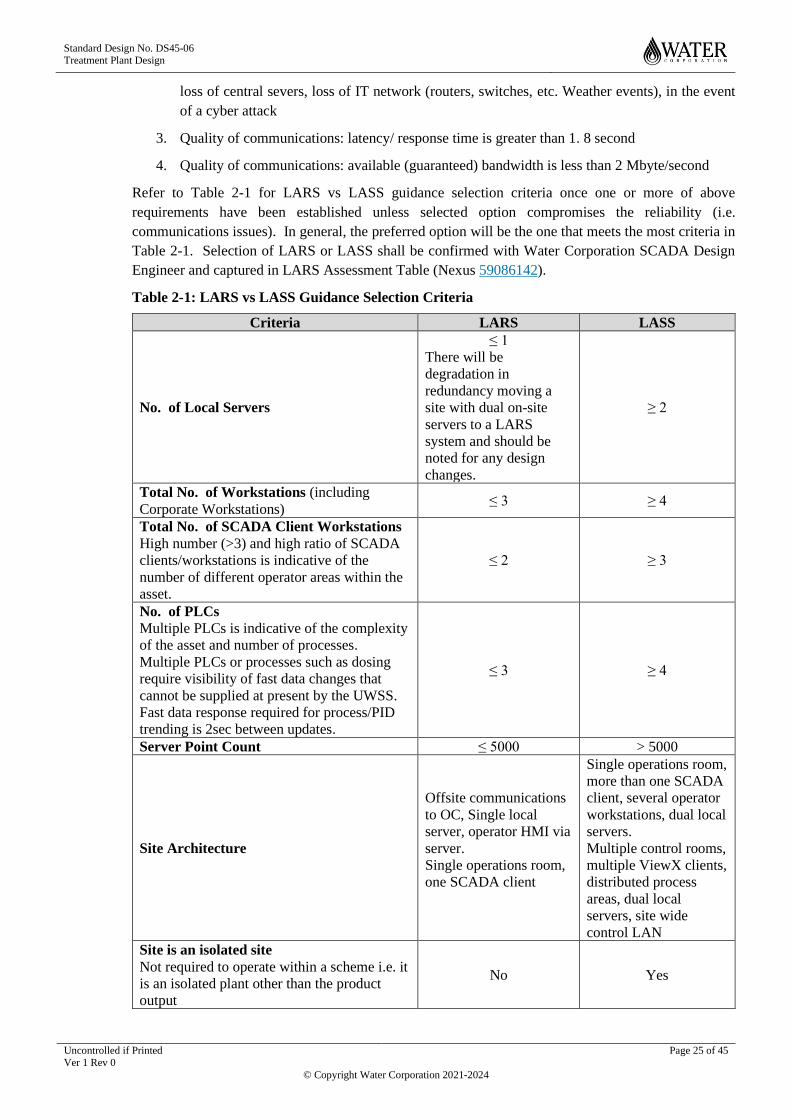
3. Quality of communications: latency/ response time is greater than 1. 8 second
4. Quality of communications: available (guaranteed) bandwidth is less than 2 Mbyte/second
Refer to Table 2-1 for LARS vs LASS guidance selection criteria once one or more of above
requirements have been established unless selected option compromises the reliability (i.e.
communications issues). In general, the preferred option will be the one that meets the most criteria in
Table 2-1. Selection of LARS or LASS shall be confirmed with Water Corporation SCADA Design
Engineer and captured in LARS Assessment Table (Nexus 59086142).
Table 2-1: LARS vs LASS Guidance Selection Criteria
Criteria LARS LASS
No. of Local Servers
≤ 1
There will be
degradation in
redundancy moving a
site with dual on-site
servers to a LARS
system and should be
noted for any design
changes.
≥ 2
Total No. of Workstations (including
Corporate Workstations) ≤ 3 ≥ 4
Total No. of SCADA Client Workstations
High number (>3) and high ratio of SCADA
clients/workstations is indicative of the
number of different operator areas within the
asset.
≤ 2 ≥ 3
No. of PLCs
Multiple PLCs is indicative of the complexity
of the asset and number of processes.
Multiple PLCs or processes such as dosing
require visibility of fast data changes that
cannot be supplied at present by the UWSS.
Fast data response required for process/PID
trending is 2sec between updates.
≤ 3 ≥ 4
Server Point Count ≤ 5000 > 5000
Site Architecture
Offsite communications
to OC, Single local
server, operator HMI via
server.
Single operations room,
one SCADA client
Single operations room,
more than one SCADA
client, several operator
workstations, dual local
servers.
Multiple control rooms,
multiple ViewX clients,
distributed process
areas, dual local
servers, site wide
control LAN
Site is an isolated site
Not required to operate within a scheme i.e. it
is an isolated plant other than the product
output
No Yes

Standard Design No. DS45-06 Treatment Plant Design
Uncontrolled if Printed Ver 1 Rev 0
Page 26 of 45
© Copyright Water Corporation 2021-2024
Criteria LARS LASS
Site is primarily controlled by Operations
Centre (OC) Yes No
Site has at least one Critical Control Point
(CCP)
Refer to the Water Safety Plan for water
treatment sites or the Process Control Table
for wastewater sites.
No Yes
Business Criticality Classification/Score
(see Nexus 49003342 ) ≤ 2 ≥ 3
Communication to the site
Communication issues are noted for
consideration and mitigation for any agreed
design changes to the architecture. Criteria
may influence architecture decision if it
cannot be mitigated.
There are no known
communication issues.
There are known
communication issues
that cannot be resolved
and the site is locally
controlled.
2.6.2.2 OIPs
Refer to DS40 Design Process for SCADA Works for selection of OIPs.
2.7 Process Instrumentation
Refer to DS40-09 Field Instrumentation.
2.8 Sub-Systems
The sub-systems likely to be encountered in treatment plants can be classified into two general types as
follows.
2.8.1 Vendor Equipment Packages
The term “Vendor Equipment Package” covers equipment that, while it may be of more or less standard
design, is manufactured or assembled to order. The Designer, as specifier, will generally have at least
some control over the type of equipment and control interface provided. Examples include filters,
chemical batching and dosing plants, aeration blowers, gas flares and the like.
Control panels for vendor equipment packages shall comply with DS26-26 where appropriate. Any
RTUs included in the package shall be of a type as specified in the SCADA Approved Equipment List.
Any deviation from this must be approved by the Principal SCADA Engineer. Refer to Section 2.5.1.2.8
for PLCs to be supplied with Vendor Equipment. More complex equipment packages shall be provided
with graphic operator interface panels which shall communicate by data link with the package PLC.
Simple packages may use panel-mounted switches, pushbuttons, indicators, alphanumeric displays and
the like.
Equipment packages shall include a LOCAL/OFF/REMOTE control location selector and shall be
specified with a control interface that will allow the PCS to control them as a unit. The interface shall
typically operate as follows:
(a) The interface shall signal to the PCS that it is available for operation when:
• Power is applied to the package,
• There are no active alarms
• All its subsystems and equipment items are ready
• Its control mode is not set to OFF
Standard Design No. DS45-06 Treatment Plant Design
Uncontrolled if Printed Ver 1 Rev 0
Page 27 of 45
© Copyright Water Corporation 2021-2024
(b) If the package’s control mode is set to OFF it shall not be possible to start it under either auto
or manual control. If it is already running it shall shut down. Selection of the OFF mode shall
immediately signal to the PCS that the package is not available.
(c) If the package’s control mode is set to LOCAL it shall be under the exclusive control of its local
control panel or control stations. PCS commands shall have no effect.
(d) If the package’s control mode is set to REMOTE it shall transmit a signal to the PCS to indicate
this. Providing the package is available for operation the PCS shall then be able to initiate or
terminate its operation by issuing or withdrawing a start command.
(e) On receipt of the PCS start command the package’s local controller shall manage all start-up
sequencing and protection functions for the drives and other equipment that make up the
package.
(f) As soon as the package has successfully completed its start-up sequence and is running normally
it shall transmit a RUNNING signal to the PCS.
(g) The package shall continuously monitor itself, whether running or not, and shall transmit
information to the PCS indicating the status of its components. The package controller shall
automatically and independently take appropriate action in the event of a fault and shall transmit
detailed alarm and diagnostic information to the PCS.
(h) Local alarm and status indication shall be provided for each drive or equipment item and for the
package as a whole. Local indication shall typically include status for each drive or equipment
item and alarm indication for each fault condition.
The Contractor undertaking the PCS works shall use an approved Water Corporation SCADA template.
This shall be developed by the Contractor undertaking the PCS works if there is no existing suitable
template. This shall be submitted to Water Corporation CCB for approval.
2.8.2 Small Vendor Equipment Control Cubicles
Vendor equipment packages are supplied with proprietary control systems that must be housed in
suitable enclosures appropriate to the environment where they are to be deployed. Such small control
cubicles:
(a) Shall comply with the requirements of “Type Specification for Low Voltage Switchboards
General Requirements DS26-09” where appropriate.
(b) Shall have a degree of protection rating of not less than IP56 where installed outdoors.
(c) Shall have a degree of protection rating of not less than IP53 where installed indoors.
(d) Equipment located within the cubicle that requires operator access shall have an IP2X rating.
For indoor cubicles this is typically achieved via mounting the equipment on the door. For
outdoor cubicles this is typically achieved via mounting the equipment on an escutcheon plate
within the cubicle.
(e) Shall have all equipment housed behind hinged lockable doors and, where installed outdoors,
with no equipment placed on the external doors of the cubicles. It is permissible to have
equipment mounted on the external door of indoor cubicles provided the degree of protection
rating is suitable for the environment and the operation and maintenance activities performed in
the area and, in any case, is not less than (c) above. All indoor cubicles shall have an electrical
isolator on the front of the door.
(f) Shall be suitably labelled as to describe the function.
Standard Design No. DS45-06 Treatment Plant Design
Uncontrolled if Printed Ver 1 Rev 0
Page 28 of 45
© Copyright Water Corporation 2021-2024
2.8.3 Ancillary Systems
2.8.3.1 Security Access Control Systems
Security Access Control Systems typically provide hardwired outputs for the following signals to the
PCS:
• Security armed/disarmed
• Security breached/not breached
• Security system healthy/fault
The security functional scope for the site will nominate the specific signals required.
2.8.3.2 CCTV
CCTV shall operate on a separate network to the PCS LANs. Exceptions will be where CCTV is used
to control or manage a process. The designer shall include this detail when submitting the LTM/PTM
request. See DS 40 Design Process for SCADA Works for details of the LTM/PTM request process.
2.9 Access and Privileges
To maintain security, the PCS shall provide several password-protected levels of access appropriate to
the needs and authority of different users. Refer to DS41-03 ClearSCADA Configuration Section 4. 3.
2.10 Power Supply
2.10.1 General
The power requirement for the site is based on the available power supplies and the site criticality.
If the site is designated as critical then battery backup power will be required and the design shall be
based on DS42-04 Communications Power Supply.
Battery backed power supply may comprise either of AC UPS systems or DC UPS / Battery Charger
Systems.
2.10.1.1 AC UPS Systems
AC UPS systems are typically applied at sites with air-conditioned environments such as switchrooms
and control rooms due to the heat generated by the equipment and associated installed temperature
rating.
AC UPS systems are either floor or rack mounted and may be specified with internal or external
batteries.
Refer to DS 26-30 or DS 26-31 for AC UPS type specifications.
2.10.1.2 DC UPS / Battery Charger Systems
DC UPS systems are also referred to as battery charger systems. They may be specified with or without
integral AC/DC conversion. Generic batteries may be connected however some vendors offer additional
monitoring capability when batteries are matched to DC UPS systems. DC UPS systems must be of the
"no-break" type where there is no delay in switchover.
DC UPS systems and batteries shall be selected from the Operational Technology Approved Equipment
List.
Standard Design No. DS45-06 Treatment Plant Design
Uncontrolled if Printed Ver 1 Rev 0
Page 29 of 45
© Copyright Water Corporation 2021-2024
2.10.2 Selection
The Designer shall aim for all instrument and control systems to be powered by Extra Low Voltage
(ELV) 24VDC supplies. In some cases this is not possible due to the power draw requirement of
particular instrumentation/actuators. Typically, automatic process analysers and valve actuators may
require 240VAC supplies.
Where critical power supply necessitating a UPS is required, the selection of DC UPS over an AC UPS
system is dependent on whether there are 240VAC elements requiring critical power supply.

Standard Design No. DS45-06 Treatment Plant Design
Uncontrolled if Printed Ver 1 Rev 0
Page 30 of 45
© Copyright Water Corporation 2021-2024
3 INSTALLATION SPECIFICATION
3.1 General
3.1.1 Network Cabling
Optic fibre cables shall be installed in accordance with the requirements of DS43-06.
Permanently-installed Shielded Twisted Pair (STP) cable (i.e. excluding patch leads) shall be installed
in conduit. STP cable shall be separated from other cables by at least 0. 5m where possible. STP cable
shall not be installed out-of-doors or underground except for runs of up to 20m between adjacent
buildings, where it may be installed underground in conduit. Cabling requirements for Ethernet based
communications are covered in section 3.1.2.
Where a ring topology is utilised, a separation of at least 2m within buildings and 6 m elsewhere shall
be maintained between any two cables in the ring configuration.
Where dual redundant LANs are provided, a separation of at least 2m within buildings and 6 m
elsewhere shall be maintained between the two LANs where possible.
3.1.2 Communications Cabling
Serial RS485 communications over route lengths exceeding 150m and Ethernet communications over
route lengths exceeding 80 m shall utilise optic fibre cables where possible.
Ethernet communications not exceeding 80m route length and contained within the one building, or
serial RS485 communications up to 150m route length whether indoor or outdoor, may use either optic
fibre or suitable screened twisted-pair cable. However, in order to reduce susceptibility to surges, optic
fibre cables shall be used for all outdoor data communications where practical.
Where metallic cable runs out-of-doors, whether underground or not, it shall be fitted with surge
suppressors at both ends in accordance with DS40-09. Separation distances between data, control and
power cables shall be in accordance with DS40-09. Cable screens shall connect to a solid ground
(normally, the metal frame of the cubicle/switchboard) with a low impedance at one end and a series
RC network at the other. This arrangement is to prevent the flow of DC ground-loop currents in the
shield.
3.1.3 Field Instrument Cabling
Individual and overall instrument cable screens shall be earthed to an instrument earth bar at the PLC
end only, unless otherwise recommended by the instrument manufacturer.
Where fieldbus communications is used and the total route length exceeds 150 metres or there is a risk
of lightning strike, electrical interference or significant earth potential rise the links shall utilise optic
fibre cable. In other cases, suitable screened twisted pair cable, fitted with surge suppressors at both
ends in accordance with DS40-09, may be used as an alternative.
Redundant or multiple paths shall be provided for multi-drop fieldbus connections to limit the extent of
control loss should one path fail. Where there are duty/standby or multiple units, a separate path shall
be provided for each. The use of a single cable to connect all items creates a serious process control
risk and shall be avoided.
It shall be possible to disconnect and reconnect individual equipment items on multi-drop fieldbus cables
without disrupting communications to other equipment on the same path.
Separation distances between data, control and power cables shall be in accordance with DS40-09.
Screens shall be earthed at the controller or PLC rack end and insulated from earth at the field end.

Standard Design No. DS45-06 Treatment Plant Design
Uncontrolled if Printed Ver 1 Rev 0
Page 31 of 45
© Copyright Water Corporation 2021-2024
For further details of instrument connection requirements refer to DS40-09.
3.1.4 Instrument Installation
In addition to the requirements of DS40-09, instruments shall be installed so that they are readily
accessible from ground, floor or walkway level for inspection, adjustment, removal and maintenance.
Special attention shall be given to ensuring that displays are easily readable.
Instruments shall be provided with lightning surge protection as required by DS40-09.
Connections for compressed air and potable water shall be provided adjacent to instruments where
required for maintenance and cleaning. Special consideration shall be given to instruments such as
dissolved oxygen and ORP probes installed through covers on aeration tanks, channels and the like. The
installation shall provide an effective odour seal while allowing the probe to be withdrawn for
inspection, cleaning, maintenance or calibration. There shall also be a temporary means of sealing the
cover penetration when the probe is withdrawn.
3.1.5 Instrument Junction Boxes
Where hard-wiring is used for field instruments, where practical, junction boxes shall be used to marshal
cables from individual instruments and control devices and to connect them to PLC I/O using multi-pair
or multicore cable. Junction boxes shall utilise rail-mounted terminal strips with at least 20% spare
terminals.
Instrument and control junction boxes shall contain ELV wiring only.
3.1.6 Switchrooms and Control Rooms
As a minimum, treatment plant sites shall feature a desk area designated for the installation of a desktop
workstation in either a switchroom or control room environment. The location of the workstation area
shall comply with DS20. Where the SCADA system hardware involves rack mounted servers and
network equipment, consideration shall be given to the installation of a suitable equipment rack in a
switchroom or control room environment at the treatment plant to house this equipment.

Standard Design No. DS45-06 Treatment Plant Design
Uncontrolled if Printed Ver 1 Rev 0
Page 32 of 45
© Copyright Water Corporation 2021-2024
4 APPROVED EQUIPMENT LIST
Refer to the Operational Technology Approved Equipment List.
Standard Design No. DS45-06 Treatment Plant Design
Uncontrolled if Printed Ver 1 Rev 0
Page 33 of 45
© Copyright Water Corporation 2021-2024
5 HAZARDOUS AREAS
5.1.1 General
A hazardous area is defined as an area in which an explosive atmosphere is present, or may be expected
to be present, in quantities such as to require special precautions for the construction, installation and
use of potential ignition sources. The explosive atmosphere may be caused by the presence of a
flammable liquid, gas or vapour or by the presence of combustible dust in suspension or in layers or a
combination of explosive gas and dust atmospheres.
Water treatment plants do not usually use or produce flammable gases or combustible dusts in sufficient
quantities to constitute an explosion risk. Water treatment examples of flammable gases or combustible
dusts are ammonia gas for chloramination; hydrogen gas as by-product of electrochlorination; and
powdered activated carbon. However, wastewater treatment plants frequently produce significant
quantities of flammable gas either deliberately or unintentionally as a by-product of the treatment
process. Therefore, explosion risks must be considered by the Designer.
The flammables gases produced in wastewater treatment consist mainly of methane and tend to be
concentrated in particular process areas including anaerobic digesters, digester-gas handling plant,
digester-gas fired boilers and generators. However, flammable gases may also accumulate in poorly-
ventilated areas containing sewage or sludge, such as enclosed air spaces above sewers, inlet channels,
screens, primary sedimentation tanks, digested and dewatered sludge storages.
Combustible dusts are generally not a problem in treatment plants, although any dry powder material
produced or used in the plant, such as dried sludge or polyelectrolyte powder, shall be assessed for
flammability and appropriate measures taken.
The Designer shall ensure that area classification, plant design and equipment selection are carried out
in accordance with the requirements of the HA Hazardous Area Classification Standard and the HA-ST-
03: EEHA Selection and Installation Standard.
5.1.2 Competency Requirements The classification of hazardous areas, the selection of electrical equipment to be used in hazardous areas
and the design of electrical installations within hazardous areas shall only be undertaken by those
persons who satisfy the requirements of HA-ST-04: EEHA Competency Standard.
5.1.3 Area Classification
Hazardous Area classification is the first step in designing the electrical installation for hazardous areas
in treatment plants. Hazardous Area classification shall be carried out in accordance with HA-ST-02:
HA Hazardous Area Classification Standard.
5.1.4 Equipment Selection
5.1.4.1 Use of Certified Equipment
All instrumentation used in hazardous areas of treatment plants shall have appropriate certification in
accordance with the requirements of HA-ST-03: EEHA Selection and Installation Standard.
5.1.4.2 Explosion-Protection Techniques
Explosion-protection techniques listed within HA-ST-03: EEHA Selection and Installation Standard are
preferred and shall be adopted in the first instance.
Other techniques maybe considered but their use is subject to approval from the Principal SCADA
Engineer and the EEHA Technical Integrity Custodian (TIC).
Standard Design No. DS45-06 Treatment Plant Design
Uncontrolled if Printed Ver 1 Rev 0
Page 34 of 45
© Copyright Water Corporation 2021-2024
5.1.4.3 Corrosive Environments
Where equipment is located in corrosive environments (e.g. hydrogen sulphide, H2S), to prevent
premature equipment failure the designer shall ensure materials for the selected equipment are suitable
for the location or that enclosures with adequate sealing to house equipment is provided.
5.1.5 Installation
Instrumentation installation design in hazardous areas shall conform to the following
(a) AS/NZS 3000:2018, “Wiring Rules”
(b) AS/NZS 60079. 14 Explosive atmospheres Part 14: Electrical installations design, selection and
erection
(c) AS/NZS 60079. 17 Explosive atmospheres Part 17: Electrical installations design, selection and
erection
(d) HA-ST-03: EEHA Selection and Installation Standard.
5.1.6 Documentation
The Designer shall prepare and maintain a hazardous area Verification Dossier in accordance with the
HA-ST-10: EEHA Verification Dossier Standard.
The Verification Dossier shall be kept up to date at all times during the design process.
Following construction and commissioning the Verification Dossier will be used by the Corporation,
maintenance contractors and future designers for maintenance purposes and for the recording of test
results, inspections, equipment overhauls, repairs and modifications and changes to area classifications.
The dossier shall therefore be prepared and maintained by the Designer with the needs of operators,
maintenance staff and future designers in mind.
The Verification Dossier shall be available for inspection by the Principal SCADA Engineer at all times
during the design phase.
5.1.7 Testing and Inspection
All new intrinsically safe circuits shall be tested to prove that there are no unintentional earths prior to
connecting the circuits to the barriers. All new intrinsically safe earth installations shall be tested prior
to commissioning to ensure that their resistance is acceptable, and that they are only connected to earth
at the specified locations.
Prior to energisation, instrumentation installed in hazardous area shall undergo initial inspection at a
detailed grade to ensure that they are correctly installed (AS/NZS 600079. 14 cl. 4.1 and AS/NZS 60079.
17 clause 4.3.1).
The following standards are applicable
(e) HA-ST-05: EEHA Inspection Standard
(f) HA-ST-06: EEHA Testing Standard

Standard Design No. DS45-06 Treatment Plant Design
Uncontrolled if Printed Ver 1 Rev 0
Page 35 of 45
© Copyright Water Corporation 2021-2024
6 WORK ON EXISTING TREATMENT PLANTS
6.1.1 General
The design of additions and upgrades to existing treatment plants shall follow the same general
principles as for new plants. However, the Designer needs to be aware of a number of issues that are
likely to arise when working on existing plants.
6.1.1.1 Site Survey
Before commencing work on additions to or upgrades of an existing treatment plant the Designer shall:
(a) Obtain copies of all available drawings and documentation for the plant from the OT Design
Advisor;
(b) Carry out a site survey of the areas affected by the new works in order to confirm the
completeness and accuracy of existing documentation and to determine the condition of the
existing installation.
Any issues arising from the site survey which may affect the scope or design of the new works shall be
reported to the OT Design Advisor.
It is strongly recommended that the Designer meets with plant operations and maintenance personnel
on a regular basis during the design phase to brief them on the proposed works and to provide an
opportunity for discussion and feedback. Such meetings shall be coordinated through the OT Design
Advisor and any proposed or requested design changes arising from them shall be referred to the OT
Design Advisor for approval.
6.1.1.2 Standards and Regulations
All new work shall conform to current Corporation, Australian and international standards and to current
statutory regulations.
Some of the standards and regulations to which existing plants, particularly older plants, have been
designed may have been superseded. In many cases this may be of little consequence. However, the
Designer will sometimes encounter compatibility or safety issues when interfacing with equipment or
facilities built to superseded standards. This is particularly so when designing additions and upgrades
to older plants that have been subject to several previous upgrades. In such cases the Designer shall
identify the issues and propose solutions for consideration by the Principal SCADA Engineer.
6.1.1.3 Safety and Environmental Issues
The conformance of existing facilities affected by the new works to current statutory requirements shall
be checked. The Designer shall refer any non-conformances, particularly those which relate to safety
or the environment, to the Principal SCADA Engineer with recommendations for resolving them. This
can be done by submitting a Request For Information/Decision that outlines the problem then describes
the potential solution and alternatives with a recommendation based on consideration of balance of
advantages and disadvantages such as practicality, reliability, cost and time impacts.
If the Designer becomes aware of any safety or environmental issues relating to existing plant or
equipment, even though the plant or equipment may not be directly affected by the new works, the issues
shall be referred in writing to the Principal SCADA Engineer.
Such issues may include:
(a) Plant or equipment that does not meet current safety or environmental regulations;
(b) Plant or equipment in poor or unsafe condition.

Standard Design No. DS45-06 Treatment Plant Design
Uncontrolled if Printed Ver 1 Rev 0
Page 36 of 45
© Copyright Water Corporation 2021-2024
Where hazardous materials are encountered, the matter shall be brought to the attention of the
Engineering Design Manager and Project Manager.
6.1.1.4 Numbering
Numbering of equipment and instruments for the new works shall be in accordance with this standard
and the equipment numbering convention described in Process Engineering design standard, DS81.
Before allocating any new numbers, the Designer shall check if any blocks of numbers have been
reserved in the existing scheme for future additions. If any such blocks exist they shall be allocated
first. For instance if the plant includes three equipment items of a particular type and a fourth item is to
be installed, numbering for the new item may already have been allocated by a previous designer.
Where numbering has not already been allocated, numbering of new equipment and instruments shall
continue existing sequences. For example if the last number used in an existing area is 1534, the new
equipment numbering could start from 1540. It is recommended that a gap be left between the old and
new numbers.
Equipment numbering in some older plants may have been carried out to older standards not compatible
with the current practice specified in DS81. These conflicts will generally be resolved as part of the
process design (which includes production and/or revision of P&IDs) rather than as part of the SCADA
design, and will resolved in accordance with the guidance provided in DS81’s section regarding
“Conflict with existing sheet numbering”.
6.1.2 Plant Control Systems
All new processes and equipment items shall be integrated into the existing SCADA system, including
all necessary updating of displays, graphics, reports, alarms, data logging, trending, programming and
documentation. For LASS sites, as a minimum equipment and instrumentation required for scheme
operation (i.e. final plant storage level, final pump station and plant outflow), critical alarms and
instrumentation and associated setpoints critical control points shall also be integrated on UWSS.
Where any work is carried out on the existing SCADA system it shall be upgraded in accordance to the
latest standard templates.
6.1.3 Programmable Controllers
Existing controller hardware affected by the new works may need to be upgraded or replaced if it is
obsolete or does not conform to current Water Corporation standards.
The upgrade and selection of controller hardware shall be clarified with Water Corporation SCADA
Design Engineer
6.1.4 Data communications
Existing copper or radio communication networks may need to be upgraded to optic fibre or IP radio as
part of the new works.
The upgrade of data communications shall be clarified with Water Corporation SCADA Design Engineer
6.1.5 Field Instrumentation
Existing field instruments may need to be upgraded or replaced to bring them into conformity with
current Water Corporation standards.
The upgrade or replacement of existing instrumentation shall be clarified with Water Corporation
SCADA Design Engineer

Standard Design No. DS45-06 Treatment Plant Design
Uncontrolled if Printed Ver 1 Rev 0
Page 37 of 45
© Copyright Water Corporation 2021-2024
6.1.6 Hazardous Areas
The Designer shall carry out a full review of existing hazardous area classifications for those areas
affected by the new works. Existing areas shall be reclassified where necessary when the hazardous
areas created by the new works overlap existing plant, or the new works are within an area that is already
classified as a hazardous area.
Re-classification shall be undertaken in accordance with HA-ST-02: HA Classification Standard with
the existing site hazardous classification report updated.
When the new works affects the hazardous area classification of existing process areas, the Designer
shall review existing electrical equipment in those areas to ensure they are suitable for the new
classification.
If the Designer becomes aware of any hazardous area non-conformance issues relating to existing plant
or equipment not affected by the new works, the issues shall be referred in writing to the Principal
SCADA Engineer.
The existing Hazardous Area Verification Dossier shall be kept up to date at all times by the addition of
new material from the new works as components and systems are designed, installed and commissioned
and brought online.
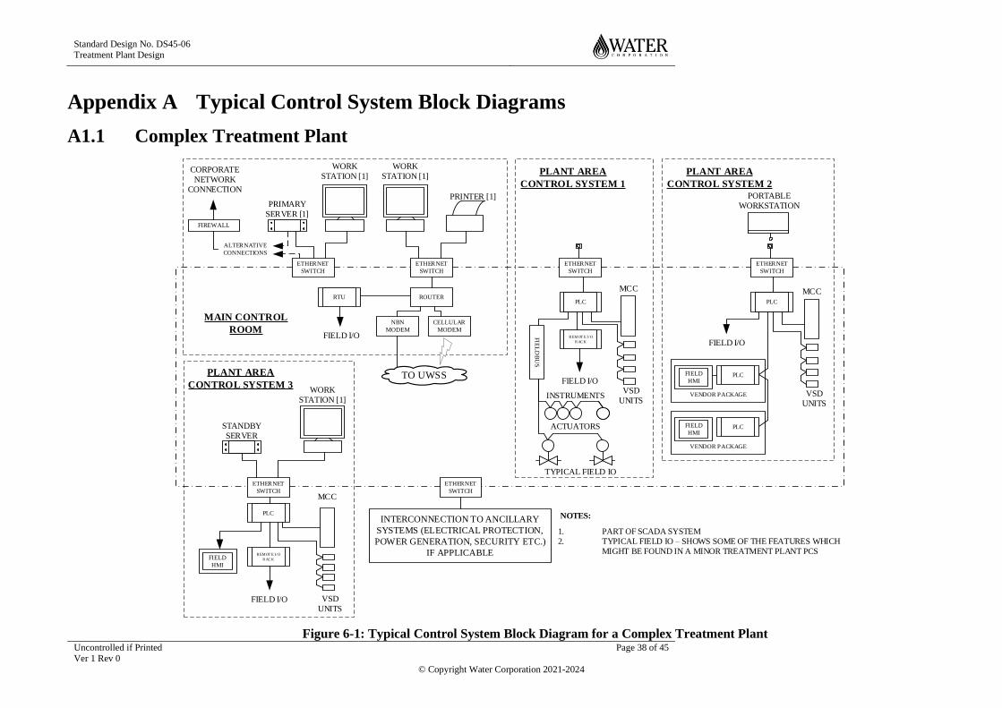
Standard Design No. DS45-06 Treatment Plant Design
Uncontrolled if Printed Ver 1 Rev 0
Page 38 of 45
© Copyright Water Corporation 2021-2024
Appendix A Typical Control System Block Diagrams
A1.1 Complex Treatment Plant
RTU
NBN
MODEM
ROUTER
CELLULAR
MODEM
FIREWALL
TO UWSS
PLC
R EMOT E I/O
R AC K
PRINTER [1]
CORPORATE
NETWORK
CONNECTION
ALTERNATIVE
CONNECTIONS
FIELD I/O
MAIN CONTROL
ROOM
FIELD I/O VSD
UNITS
MCC
PRIMARY
SERVER [1]
ETHERNET
SWITCH
ETHERNET
SWITCH
WORK
STATION [1]
WORK
STATION [1]
WORK
STATION [1]
STANDBY
SERVER
ETHERNET
SWITCH
FIELD
HMI
PLANT AREA
CONTROL SYSTEM 3
ETHERNET
SWITCH
PLC
R EMOT E I/ O
R AC K
PLANT AREA
CONTROL SYSTEM 1
FIELD I/O
INSTRUMENTS
ACTUATORS
TYPICAL FIELD IO
VSD
UNITS
MCC
FIE
LD
BU
S
ETHERNET
SWITCH
PLC
PLANT AREA
CONTROL SYSTEM 2
FIELD I/O
VSD
UNITS
MCC
VENDOR PACKAGE
FIELD
HMIPLC
VENDOR PACKAGE
FIELD
HMIPLC
ETHERNET
SWITCH
INTERCONNECTION TO ANCILLARY
SYSTEMS (ELECTRICAL PROTECTION,
POWER GENERATION, SECURITY ETC.)
IF APPLICABLE
1. PART OF SCADA SYSTEM
2. TYPICAL FIELD IO – SHOWS SOME OF THE FEATURES WHICH
MIGHT BE FOUND IN A MINOR TREATMENT PLANT PCS
NOTES:
PORTABLE
WORKSTATION
Figure 6-1: Typical Control System Block Diagram for a Complex Treatment Plant

Standard Design No. DS45-06 Treatment Plant Design
Uncontrolled if Printed Ver 1 Rev 0
Page 39 of 45
© Copyright Water Corporation 2021-2024
BLANK PAGE
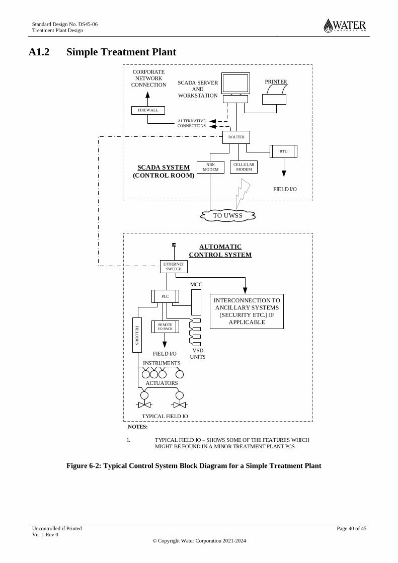
Standard Design No. DS45-06 Treatment Plant Design
Uncontrolled if Printed Ver 1 Rev 0
Page 40 of 45
© Copyright Water Corporation 2021-2024
A1.2 Simple Treatment Plant
RTU
NBN
MODEM
ROUTER
CELLULAR
MODEM
FIREWALL
TO UWSS
ETHERNET
SWITCH
PLC
REMOTE
I/O RACK
PRINTERSCADA SERVER
AND
WORKSTATION
CORPORATE
NETWORK
CONNECTION
ALTERNATIVE
CONNECTIONS
FIELD I/O
SCADA SYSTEM
(CONTROL ROOM)
AUTOMATIC
CONTROL SYSTEM
FIELD I/O
INSTRUMENTS
ACTUATORS
TYPICAL FIELD IO
VSD
UNITS
MCC
INTERCONNECTION TO
ANCILLARY SYSTEMS
(SECURITY ETC.) IF
APPLICABLE
1. TYPICAL FIELD IO – SHOWS SOME OF THE FEATURES WHICH
MIGHT BE FOUND IN A MINOR TREATMENT PLANT PCS
NOTES:
FIE
LD
BU
S
Figure 6-2: Typical Control System Block Diagram for a Simple Treatment Plant

Standard Design No. DS45-06 Treatment Plant Design
Uncontrolled if Printed Ver 1 Rev 0
Page 41 of 45
© Copyright Water Corporation 2021-2024
BLANK PAGE

Standard Design DS 45-06
Treatment Plant Design
Uncontrolled if Printed Ver 1 Rev 0
Page 42 of 45
© Copyright Water Corporation 2021-2021
Appendix B LARS & LASS
B1.1 LASS Typical Architecture
Figure 6-3: Local Area Site Server (LASS) Typical Architecture
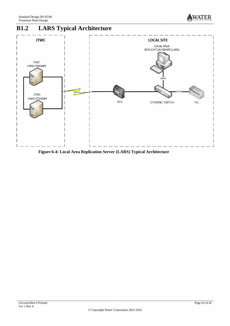
Standard Design DS 45-06
Treatment Plant Design
Uncontrolled if Printed Ver 1 Rev 0
Page 43 of 45
© Copyright Water Corporation 2021-2021
B1.2 LARS Typical Architecture
Figure 6-4: Local Area Replication Server (LARS) Typical Architecture

Standard Design DS 45-06
Treatment Plant Design
Uncontrolled if Printed Ver 1 Rev 0
Page 44 of 45
© Copyright Water Corporation 2021-2021
B1.3 Data Transmission Paths
LASS
JTWC SCADA Network
Permanent StandbyUWSS
Site Server (S)
JWTC / OpsClients
Local Client(s)
RTU
PLC
Router
UWSS
RemoteCommunications
LARS
JTWC SCADA Network
Permanent StandbyUWSS
Site Server (S)
JWTC / OpsClients
Local Client(s)
RTU
PLC
Router
UWSS
RemoteCommunications
Communications Path Key
Green = UWSS data
Purple = Site Server data
Orange = JTWC Client
Red = Local Client
Brown = PLC to RTU
Blue = Synchronise data to permanent standby
The only differences are:
Where the Site Server gets its data from (Purple)
Synchronising data across the Telecoms (Blue)

Standard Design DS 45-06
Treatment Plant Design
Uncontrolled if Printed Ver 1 Rev 0
Page 45 of 45
© Copyright Water Corporation 2021-2021
END OF DOCUMENT


