Page 1 of 4 January 27, 2012 Re: TRI-COUNTY COUNCIL / SHORE TRANSIT BUS MAINTENANCE FACILITY PHASE II Salisbury, Maryland 2009145.00 ADDENDUM THREE The contract documents for the above referenced project, dated January 5, 2012 are amended as follows: CLARIFICATION 1. Reply to Bidders Question #2 “DBE forms A&B must be submitted with the bid and forms C&D must be received no later than 14 days after the bid due date/time.” (issued via addendum #2 dated 2/20/12) is to be replaced with the following reply: “DBE forms A&B must be submitted with the bid and forms C&D must be received no later than 10 days after the bid due date/time.” 2. Due to the extension of the bid period (as noted in Addendum #2) the last day for bidders questions will be extended to Wednesday 2/1/12- end of business day. Addendum #4 will be issued 2/3/12. 3. See attached Bidders Questions & Answers spreadsheet attached via this addendum 4. Note Allen & Shariff RFI PCO log attachments relates to the Bidders Questions & Answers spreadsheet attached via this addendum 5. Acceptable manufacturers for cast stone cap at site sign (details 4&5/A503 see also bidders/questions and answers question #9 issued via this addendum) are as follows: American Artstone Co., Inc. Architectural Cast Stone Corp. Architectural Cast Stone, Inc. Architectural Concrete Co., Inc. ConArt, Inc. Continental Cast Stone East, by Russell, Inc. Dallas Cast Stone Co., Inc. DuraStone. Edwards Precast Concrete Co. Kerckhoff: D. C. Kerckhoff Co. Miller Precast, Inc. Olympian Precast, Inc Plasticrete Architectural Concrete Products. Sun Precast Co., Inc PROJECT MANUAL 1. TABLE OF CONTENTS a. ADD SECTION 105113 b. ADD SECTION 096724 2. SECTION 012300- ALTERNATES
Transcript
Page 1 of 4
January 27, 2012 Re: TRI-COUNTY COUNCIL / SHORE TRANSIT BUS MAINTENANCE FACILITY PHASE II Salisbury, Maryland 2009145.00 ADDENDUM THREE The contract documents for the above referenced project, dated January 5, 2012 are amended as follows: CLARIFICATION 1. Reply to Bidders Question #2 “DBE forms A&B must be submitted with the bid and forms C&D must be received
no later than 14 days after the bid due date/time.” (issued via addendum #2 dated 2/20/12) is to be replaced with the following reply: “DBE forms A&B must be submitted with the bid and forms C&D must be received no later than 10 days after the bid due date/time.”
2. Due to the extension of the bid period (as noted in Addendum #2) the last day for bidders questions will be
extended to Wednesday 2/1/12- end of business day. Addendum #4 will be issued 2/3/12. 3. See attached Bidders Questions & Answers spreadsheet attached via this addendum 4. Note Allen & Shariff RFI PCO log attachments relates to the Bidders Questions & Answers spreadsheet attached
via this addendum 5. Acceptable manufacturers for cast stone cap at site sign (details 4&5/A503 see also bidders/questions and answers
question #9 issued via this addendum) are as follows: American Artstone Co., Inc.
Architectural Cast Stone Corp. Architectural Cast Stone, Inc. Architectural Concrete Co., Inc. ConArt, Inc. Continental Cast Stone East, by Russell, Inc. Dallas Cast Stone Co., Inc. DuraStone. Edwards Precast Concrete Co. Kerckhoff: D. C. Kerckhoff Co. Miller Precast, Inc. Olympian Precast, Inc Plasticrete Architectural Concrete Products. Sun Precast Co., Inc
PROJECT MANUAL 1. TABLE OF CONTENTS
a. ADD SECTION 105113 b. ADD SECTION 096724
2. SECTION 012300- ALTERNATES
Page 2 of 4
a. REPLACE section in it’s entirety with attached 3. SECTION 003000- BID FORM
a. REPLACE bid form in its entirety with attached 4. SECTION 042000- UNIT MASONRY
REPLACE section 2.5-B-3 with the following
3. Finish (basis of design) :
Face brick Type A: Include the cost of $2,198/M for the following selections:
1) Belden – 8621
Face brick Type B: Include the cost of $2,098/M for the following selections: 1)Belden – Potomac Clear
Face brick Type C: Include the cost of $5,940/M for the following selections:
1)Belden – Black Glazed Monarch
5. SECTON 071326 SELF-ADHERING WATERPROOFING a. REPLACE section 1.2-A-1 “Summary” with
A. This section includes the following: 1.Rubberized asphalt sheet waterproofing for positive side applications 2.Composite sheet drainage for positive drainage and membrane protection 3.Composite sheet waterproofing for blind side applications
b. ADD to section 2.1-A-1 “Products” h. Seaboard Asphalt Products Company, LN-16 Polymer Modified Coating
6. SECTION 074113 METAL ROOF PANELS
a. ADD to section 2.1-A “Manufacturers”
4. NUCOR Building Systems 5.CCG-CSI Steel
b. ADD to section 2.1-E-1 “Panels”
e.. Equivalent product (NUCOR VR16 II) by NUCOR Building Systems, 201 Granite Drive, Suite 280, Lancaster,PA 17601
f. Equivalent product (SSS2 Panel) by CCG, 650 Rosewood Drive, P.O. Box 1756, Columbia, SC 29202
c. ADD to section 2.4-A-2
b. Color: Sandstone CR from Garland Color Selector/Standard Colors
7. SECTION 074213 METAL WALL PANELS
Page 3 of 4
a. ADD to section 2.3 –A “Exterior wall panels” i. Wall panel gauge/Thickness to be .040”
8. SECTION 096724-RESINOUS FLOORING (2) a. ADD section in its entirety
9. SECTION 105113-METAL EVIDENCE LOCKERS a. ADD section in its entirety
a. Revise the first sentence of Note FS-17 on Sheet C-304 to read: “ INSTALL THREE (3) DOUBLEWALL HORIZONTAL CYLINDRICAL FIREGUARD AST’S MEETING UL-2085.”
b. In Note FS-17 on Sheet C-304 delete the sentence ”PROVIDE LADDERS AND WALKWAYS TO ACCESS THE TOP OF TANKS.” and replace with “ FITTINGS SHALL BE INSTALLED IN THE MOST COMPACT CONFIGURATION POSSIBLE CLOSE TO THE LADDER END OF EACH TANK. PROVIDE LADDERS AND WALKWAYS WHICH EXTEND FOR THE ENTIRE LENGTH OF THE FITTINGS TO FACILITIATE SAFE ACCESS TO THE FITTINGS.”
c. The HIGHGUARD Oil Water Separator detailed on Sheet C-304 must be manufactured per UL-2215 with all sensors and alarms required. Provide number and size of electrical conduits as required by manufacturer to alarm panels in building. Alarm Panels to be mounted adjacent to Fuel Depot controls in the Maintenance Building room 107. 2. SHEET –E-102 – ELECTRICAL SCHEDULES & DIAGRAMS (ALLEN & SHARIFF)
a. Replace sheet E-102 in it’s entirety with revised sheet E-102 issued via Addendum #3 3. SHEET –E-201 – ELECTRICAL POWER PLANS (ALLEN & SHARIFF)
a. Replace sheet E-201in it’s entirety with revised sheet E-201 issued via Addendum #3
4. SHEET A-201 – ELEVATIONS
a. Replace detail 6/A201 with BMG sketch MTA-SK-3 dated 1/26/12 issued via Addendum #3
i. Floor finish to be CONC-SEAL - base bid /EPX2 - add/alt #10 in the following areas: BAY 1-101 ,BAY 2-102,BAY 3-103, BAY 4-104
b. Revise finish legend as follows:
i. Replace- spec reference for CONC-SEAL from 03 36 00 to 03 33 00 in finish legend.
ii. Add- EPX2-EPOXY RESIN – TYPE 2 (ADD/ALT #10) spec ref 09 67 24 to finish legend.
iii. Delete – P- POLISHED/STAINED CONCRETE from finish legend.
c. Revise Window Type 2 as follows: “Sliding Aluminum window unit set in hollow metal frame @ Admin. Assistant 113.
Attachments: Bidders Questions & Answers through 1/26/12 Product Data Sheet- LN-16 Polymer Modified Foundation Coating by “Seaboard Asphalt Products Company”
Allen & Shariff Engineering RFI-PCO Log dated 1/27/2012 Section 012300, Alternates Section 003000, Bid Form Section 096724, Resinous Flooring (2) Section 105113, Metal Evidence Lockers Morabito Consultants Inc. Sketch S01 dated 1/26/12 ( 8.5 x 11” sheet) BMG, Sketch MTA-SK-3 dated 1/26/12 (11”x17” sheet) Allen & Shariff Engineering, Drawing E-102 (24”x36” sheet) Allen & Shariff Engineering, Drawing E-201 (24”x36” sheet) END OF ADDENDUM NO. THREE
200914500_Addendum3-bus-main.doc
BECKER MORGAN GROUP TCC-SHORE TRANSIT – BUS MAINTENANCE FACILITY - PHAS E II
BIDDERS’ QUESTIONS & ANSWERS THROUGH 1/26/12
Q # ANSWER
BY –SKETCH #
QUESTION / COMMENT ANSWER SPEC. DIV .
Tri County Council – Shore Transit – Bus Maintenance Facility- Phase II Questions Page 1 of 9
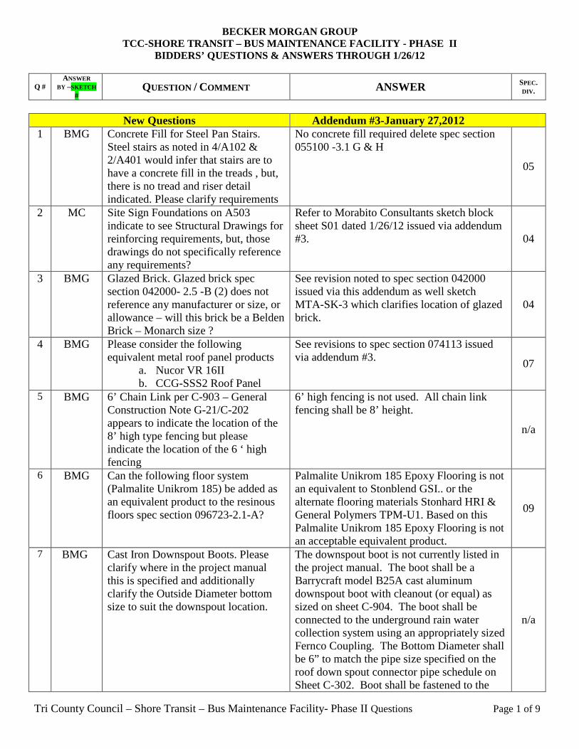
New Questions Addendum #3-January 27,2012 1 BMG Concrete Fill for Steel Pan Stairs.
Steel stairs as noted in 4/A102 & 2/A401 would infer that stairs are to have a concrete fill in the treads , but, there is no tread and riser detail indicated. Please clarify requirements
No concrete fill required delete spec section 055100 -3.1 G & H
05
2 MC Site Sign Foundations on A503 indicate to see Structural Drawings for reinforcing requirements, but, those drawings do not specifically reference any requirements?
Refer to Morabito Consultants sketch block sheet S01 dated 1/26/12 issued via addendum #3. 04
3 BMG Glazed Brick. Glazed brick spec section 042000- 2.5 -B (2) does not reference any manufacturer or size, or allowance – will this brick be a Belden Brick – Monarch size ?
See revision noted to spec section 042000 issued via this addendum as well sketch MTA-SK-3 which clarifies location of glazed brick.
04
4 BMG Please consider the following equivalent metal roof panel products
a. Nucor VR 16II b. CCG-SSS2 Roof Panel
See revisions to spec section 074113 issued via addendum #3.
07
5 BMG 6’ Chain Link per C-903 – General Construction Note G-21/C-202 appears to indicate the location of the 8’ high type fencing but please indicate the location of the 6 ‘ high fencing
6’ high fencing is not used. All chain link fencing shall be 8’ height.
n/a
6 BMG Can the following floor system (Palmalite Unikrom 185) be added as an equivalent product to the resinous floors spec section 096723-2.1-A?
Palmalite Unikrom 185 Epoxy Flooring is not an equivalent to Stonblend GSI.. or the alternate flooring materials Stonhard HRI & General Polymers TPM-U1. Based on this Palmalite Unikrom 185 Epoxy Flooring is not an acceptable equivalent product.
09
7 BMG Cast Iron Downspout Boots. Please clarify where in the project manual this is specified and additionally clarify the Outside Diameter bottom size to suit the downspout location.
The downspout boot is not currently listed in the project manual. The boot shall be a Barrycraft model B25A cast aluminum downspout boot with cleanout (or equal) as sized on sheet C-904. The boot shall be connected to the underground rain water collection system using an appropriately sized Fernco Coupling. The Bottom Diameter shall be 6” to match the pipe size specified on the roof down spout connector pipe schedule on Sheet C-302. Boot shall be fastened to the
n/a
BECKER MORGAN GROUP TCC-SHORE TRANSIT – BUS MAINTENANCE FACILITY - PHAS E II
BIDDERS’ QUESTIONS & ANSWERS THROUGH 1/26/12
Q # ANSWER
BY –SKETCH #
QUESTION / COMMENT ANSWER SPEC. DIV .
Tri County Council – Shore Transit – Bus Maintenance Facility- Phase II Questions Page 2 of 9
structure in accordance with the manufacturer’s recommendations.
8 BMG Section 071326 Self-Adhered Sheet Waterproofing indicates to provide to below grade structures. Insofar as the exterior masonry foundations noted on A302,A303 & A304 do not indicate any waterproofing requirement – please specifically indicate required location(s) .
See revised summary of spec section 071326 1.2-A for clarification regarding self-adhered sheet waterproofing. Note additional product (LN-16 Polymer Modified Foundation Coating by Seaboard Asphalt Products Company) added to spec section 071326-2.1-a-1) via this addendum.
07
9 BMG Cast Stone Copings for site signage masonry do not appear to be specified in Division 4?
No spec section is provided for cast stone coping as it only occurs at site sign (sheet A503). Provide cast stone cap/coping that complies with ASTM C1364. Provide shop drawing submittal that includes product data for material and fabrication/installation details. Cast stone to be provided from the list of manufacturers included in the clarification section of Addendum #3.
04
10 BMG MC
Floor deck screed angles are noted as 16 gauge ( Section 053114 para 2.3 B) but 18 gauge on 8/S302?
18 gauge screed angles are acceptable. Detail 8/S302 supersedes specifications in this case.
05
11 BMG MC
Steel Roof Deck. Metal deck general notes on S202 reference “ painted deck” whereas Section 053123 references” galvanizing” in Part 2 Products-Please clarify the deck requirement.
Metal roof deck shall be galvanized if exposed to weather but can be shop painted if protected from water. Refer to architectural drawings where waterproof roofing is provided.
05
12 BMG MC
Sections 1 7 2/A501 both reference 3-5/8” metal stud soffit framing but the arrow indicates the same location as the joist extension? -additionally insofar as details on S401/S402 indicate structural outriggers we seek to clarify the metal stud framing reference at those locations?
Metal studs as specified by the architectural drawings shall be infill between structural cantilevered/outrigger members.
05
13 BMG Section 055000 1.2A references ladders, steel corner guards, edgings etc but, the architectural drawings do not appear to so indicate ?
No ladders are included in project, steel corner guards per detail 1/A501. Edgings to be provided at slab edge in mechanical mezzanine 124 and parts mezzanine 125
05
14 BMG Section 099123 Interior Painting. Please clarify the requirement or any requirement that exposed structural
Steel joist and underside of deck are to have field finish paint per 099123 09
BECKER MORGAN GROUP TCC-SHORE TRANSIT – BUS MAINTENANCE FACILITY - PHAS E II
BIDDERS’ QUESTIONS & ANSWERS THROUGH 1/26/12
Q # ANSWER
BY –SKETCH #
QUESTION / COMMENT ANSWER SPEC. DIV .
Tri County Council – Shore Transit – Bus Maintenance Facility- Phase II Questions Page 3 of 9
steel – steel joist –or the underside of exposed metal decking be “ finished painted” beyond the prime coats for those products. Steel stair systems we would understand to be field finished painted –please specifically clarify on all.
15 BMG Section 055213 references “ ….. handrails/guardrails at the Auditorium Building” - ? Additionally, it would appear that the Metal Stair Railings are the only project applicable railings and those railings appear as specified in Section 055100 para. 1.2 - therefore is Section 055213 to be deleted as redundant and not applicable
Modify 055213-1-paragraph 1.2.A.1 “Mezzanine and Parts storage areas” in lieu of “auditorium building”
05
16 BMG Steel Stairs – a previous question had referenced the steel stairs and the question of concrete fill as may be indicated in 4/A102 but a further review also indicates the use of metal bar grating in Section 055100 para. 2.7 C – therefore please clarify the type of tread and risers required for the stair systems. Additionally, para. 2.9 E indicates to “ Finish Paint: Safety Yellow Paint ? Does this mean that the entire steel stair system including treads /risers be painted “ Safety Yellow Paint? What is required for the Finish Painting of the Railings/Guardrails System?
Treads to be metal bar grate w/non-slip surface. Safety paint all stair surfaces excluding treads
05
17 BMG TCC
General decision wage rates in section 004343 of the spec. Are different from the wages that were specified on the TCC/EDA-site improvements project that is currently under construction. Please clarify that the wage rates in the spec. are correct.
Wage rates in spec. are correct
00
18 BMG MC
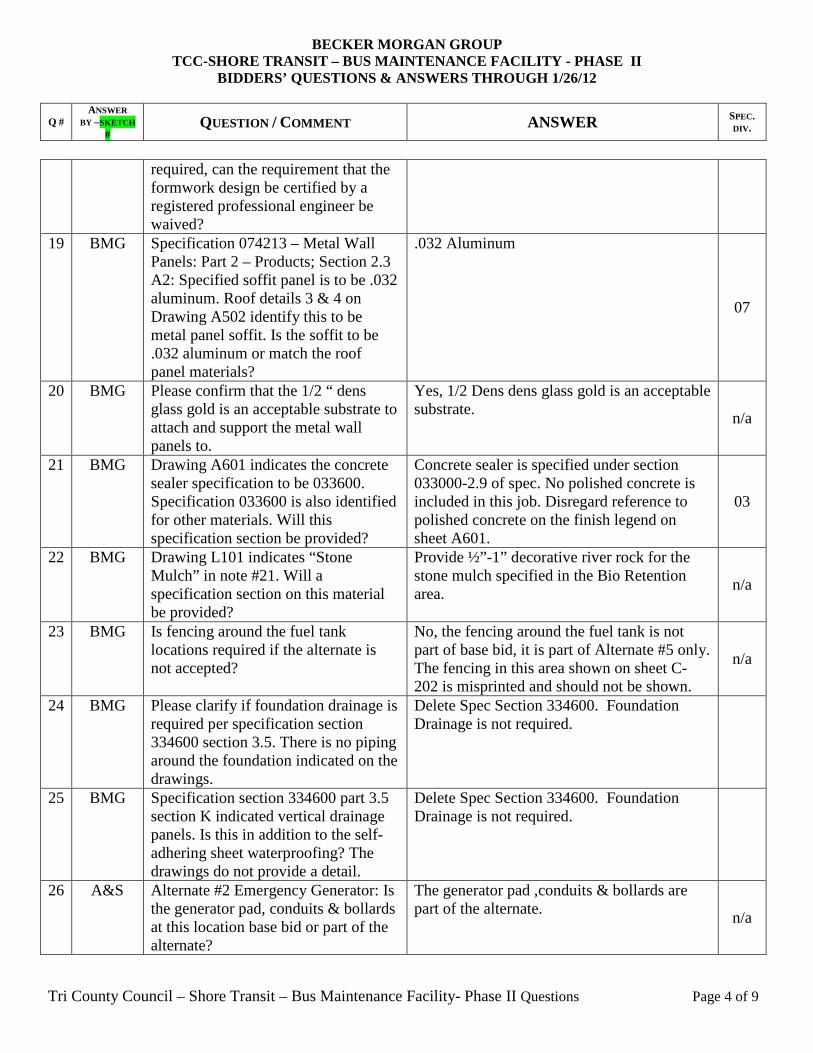
Section 031100 – Concrete Forming: Part 1 – General; Section 1.2 item A2: Due to the volume of formwork
Formwork documentation does not need be certified by a registered engineer.
03
BECKER MORGAN GROUP TCC-SHORE TRANSIT – BUS MAINTENANCE FACILITY - PHAS E II
BIDDERS’ QUESTIONS & ANSWERS THROUGH 1/26/12
Q # ANSWER
BY –SKETCH #
QUESTION / COMMENT ANSWER SPEC. DIV .
Tri County Council – Shore Transit – Bus Maintenance Facility- Phase II Questions Page 4 of 9
required, can the requirement that the formwork design be certified by a registered professional engineer be waived?
19 BMG Specification 074213 – Metal Wall Panels: Part 2 – Products; Section 2.3 A2: Specified soffit panel is to be .032 aluminum. Roof details 3 & 4 on Drawing A502 identify this to be metal panel soffit. Is the soffit to be .032 aluminum or match the roof panel materials?
.032 Aluminum
07
20 BMG Please confirm that the 1/2 “ dens glass gold is an acceptable substrate to attach and support the metal wall panels to.
Yes, 1/2 Dens dens glass gold is an acceptable substrate.
n/a
21 BMG Drawing A601 indicates the concrete sealer specification to be 033600. Specification 033600 is also identified for other materials. Will this specification section be provided?
Concrete sealer is specified under section 033000-2.9 of spec. No polished concrete is included in this job. Disregard reference to polished concrete on the finish legend on sheet A601.
03
22 BMG Drawing L101 indicates “Stone Mulch” in note #21. Will a specification section on this material be provided?
Provide ½”-1” decorative river rock for the stone mulch specified in the Bio Retention area.
n/a
23 BMG Is fencing around the fuel tank locations required if the alternate is not accepted?
No, the fencing around the fuel tank is not part of base bid, it is part of Alternate #5 only. The fencing in this area shown on sheet C-202 is misprinted and should not be shown.
n/a
24 BMG Please clarify if foundation drainage is required per specification section 334600 section 3.5. There is no piping around the foundation indicated on the drawings.
Delete Spec Section 334600. Foundation Drainage is not required.
25 BMG Specification section 334600 part 3.5 section K indicated vertical drainage panels. Is this in addition to the self-adhering sheet waterproofing? The drawings do not provide a detail.
Delete Spec Section 334600. Foundation Drainage is not required.
26 A&S
Alternate #2 Emergency Generator: Is the generator pad, conduits & bollards at this location base bid or part of the alternate?
The generator pad ,conduits & bollards are part of the alternate.
n/a
BECKER MORGAN GROUP TCC-SHORE TRANSIT – BUS MAINTENANCE FACILITY - PHAS E II
BIDDERS’ QUESTIONS & ANSWERS THROUGH 1/26/12
Q # ANSWER
BY –SKETCH #
QUESTION / COMMENT ANSWER SPEC. DIV .
Tri County Council – Shore Transit – Bus Maintenance Facility- Phase II Questions Page 5 of 9
27 BMG A&S
Notes R-16 & 17 indicate telephone and CATV cabling to be relocated on drawing C-101. Drawing C-401 shows these cables in the same location. Are we responsible for their relocation?
Note R-16 and R-17 shall not apply for bidding. Contractor must include test-pit of communications lines to determine depth and if they will interfere with ant proposed work. Report depth & elevation to the engineer prior to disturbance of land above the lines. If lines must be lowered or relocated then the owner will make arrangements for that to be done.
28 BMG Drawing 503 indicates (2) site signs. Based on drawing C-201 theses signs appear to be outside of the limits of disturbance. Are these signs part of base bid?
Signs are included in the base bid. Note that sign #2 at the main entry to the project (detail 3/A503) has been deleted. 04
29 BMG Will a specification be provided for the empty fare box and pass through shown on drawing A701 details 9&10?
See spec section 105113 added via addendum #3
10
30 BMG Alternate #5 Fuel Depot: Will structural details be provided for the canopy to be erected as part of this alternate?
No. It is the responsibility of the Contractor to provide a delegated-design submittal for review and approval as outlined in Specification Section 114000 for all fuel depot equipment, parts and appurtenances.
n/a
31 BMG Alternate #4 Wash Bay Addition: What structural detail is used if alternate 4 is not accepted as it relates to the interior wall that divides Room 126 from rooms 106 thru 110? Will an elevation of this wall be provided? Is the foundation and footing for the exterior wall of room 126 to be provided under base bid?
If alternate wash bay addition is not built, the exterior wall (interior of the alternate wash bay) shall be constructed per structural detail 15/S201.
n/a
32 Section 074213 Metal Wall Panels – please clarify on the following items:
a- Panel Gauge/Thickness appears noted as .032” for the Soffits (para. 2.3A-2) but the Wall Panel does not appear to indicate the required Thickness/Gauge?
b- Blanket Wall Insulation is noted in para. 2.4 – but- detail 3/A502 indicates insulation via the foamed-in-place insulation- so- we
a- Wall panel to be .040” b- Delete paragraph 2.4, see section
072100 for insulation
07
BECKER MORGAN GROUP TCC-SHORE TRANSIT – BUS MAINTENANCE FACILITY - PHAS E II
BIDDERS’ QUESTIONS & ANSWERS THROUGH 1/26/12
Q # ANSWER
BY –SKETCH #
QUESTION / COMMENT ANSWER SPEC. DIV .
Tri County Council – Shore Transit – Bus Maintenance Facility- Phase II Questions Page 6 of 9
assume the blanket insulation is n/a?
33 BMG Section 077200 Roof Accessories
references Roof Curbs, Roof Hatches and Heat and Smoke Vents none of which appear to be indicated on A103 Roof Plan? Please Clarify
Correct, no roof accessories on project. Only penetrations thru metal roof are for mechanical and plumbing vents. See drawing A103 & MEP drawings
07
34 BMG Elevation 2 /A601 references “ Aluminum Storefront @ Admin Assist 113” but section H1 /J1 indicate Hm framing? Additionally , section 6/A401 cut thru the opening on 3/A401 is not clear.Is the intent for a sliding Aluminum window unit set in a Hm frame ? Additionally, the spec references Interior Storefront Framing ( Kawneer Trifab VG 451) but all storefront/clerestory windows appear as exterior storefront framing systems ( Kawneer Trifab VG 451T – Thermal ) – otherwise , please locate any interior storefront framing systems
See revision to drawing A601 (issued via this addendum) in regards to window elevation #2. Intent is to provide a sliding aluminum window unit set in a hollow metal frame. Correct, there are no interior store front/clerestory windows in the project. Delete paragraph 2.4B in spec section 084113.
08
35 BMG Monumental Site Signs are referenced as ADD/ALT 9 on A503? The schedule of Alternates does not appear to reference the work on this sheet as any Alternate. Please clarify if all work this Sheet is the Base Bid ? Additionally , we assume Section 101400 para. 2.2 D ( Exterior Panel Signs) is the performance requirements for the Signage portion?
Monumental site sign is part of the base bid. See attached clarifications to sheet A503 which is attached in the drawings section of addendum #3. Exterior panel performance spec. section correct as noted.
10
36 A&S What is the spec on the grease piping. I can find no spec on the piping.
See response – RFI question # 40 from Allen & Shariff Engineering RFI log dated 1/26/12 that is issued via addendum #3
n/a
37 A&S Please Revise/Clarify UL & API requirements in Division 231113, paragraphs 2.13 & 2.14
See response – RFI question # 9 from Allen & Shariff Engineering RFI log dated 1/26/12 that is issued via addendum #3
38 MC Will engineer stamped shop drawings be required for cold formed metal stud framing for this project
It is the structural engineer’s understanding that all metal stud framing for this job is non-structural.
05
BECKER MORGAN GROUP TCC-SHORE TRANSIT – BUS MAINTENANCE FACILITY - PHAS E II
BIDDERS’ QUESTIONS & ANSWERS THROUGH 1/26/12
Q # ANSWER
BY –SKETCH #
QUESTION / COMMENT ANSWER SPEC. DIV .
Tri County Council – Shore Transit – Bus Maintenance Facility- Phase II Questions Page 7 of 9
39 A&S Drawing Note #1 on Drawing “E300” is asking for one (1) 1” conduit to be installed from the front gate to the Maintenance Building. The distance exceeds 600’; we would recommend at least one pull box should be installed. Also, circuit SB-15 for the gate power is similar in length but there is no increase in conductor size to compensate for voltage drop. Please clarify if any modifications need to be made.
See response – additional RFI questions received from contractors # 1 from Allen & Shariff Engineering RFI log dated 1/26/12 that is issued via addendum #3
n/a
40 A&S Drawing Note #7 on Drawing “E300” is asking for one (1) ¾” conduit to be installed from the sign location to an existing pull box. It is more than 1000’ and there isn’t any pull boxes?? Also, to install this ¾” conduit from the existing pull box would you prefer to sawcut the existing concrete/blacktop surfaces or horizontal bore under the concrete and/or paving?
See response – additional RFI questions received from contractors # 2 from Allen & Shariff Engineering RFI log dated 1/26/12 that is issued via addendum #3
n/a
41 A&S Division 260519, Part 2 is stating THW insulation to be installed throughout the project. According to South Wire, THW is not available; is it acceptable to use THHN/THWN insulation which is an industry standard and readily available?
See response – additional RFI questions received from contractors # 3 from Allen & Shariff Engineering RFI log dated 1/26/12 that is issued via addendum #3 n/a
42 A&S Please clarify if a CR20 receptacle, which is a Spec Grade that satisfies the requirement on “E100” or will Division 262726 require the project to use 5262 Series receptacles. Also, “E100” states to provide plastic plates and 262726 states to provide stainless steel plates. Please clarify.
See response – additional RFI questions received from contractors # 4 from Allen & Shariff Engineering RFI log dated 1/26/12 that is issued via addendum #3
n/a
43 A&S Division 260553, 2.4 states conduit markers to be installed on each 208 volt system; conduit longer than 6’ and every 20’ on center. Please clarify (a) does this apply to feeders only that are 208 volts, (b) does this
See response – additional RFI questions received from contractors # 5 from Allen & Shariff Engineering RFI log dated 1/26/12 that is issued via addendum #3
n/a
BECKER MORGAN GROUP TCC-SHORE TRANSIT – BUS MAINTENANCE FACILITY - PHAS E II
BIDDERS’ QUESTIONS & ANSWERS THROUGH 1/26/12
Q # ANSWER
BY –SKETCH #
QUESTION / COMMENT ANSWER SPEC. DIV .
Tri County Council – Shore Transit – Bus Maintenance Facility- Phase II Questions Page 8 of 9
apply to branch circuits that are 208 volts, (c) are 208/120 volt feeders and branch circuits exempt, and (d) the color and size of the label is not specified??
44 A&S Division 263213, 3.2 states to provide a portable loadbank test on the generator, if required. Will an onsite full loadbank test be required?
See response – additional RFI questions received from contractors # 6 from Allen & Shariff Engineering RFI log dated 1/26/12 that is issued via addendum #3
n/a
45 A&S Note 6 on Drawing “E301” states the requirements for the natural gas service for the proposed generator is to be provided by Division 26 (electrical). Normally gas piping is provided by the mechanical division. Please confirm.
See response – additional RFI questions received from contractors # 7 from Allen & Shariff Engineering RFI log dated 1/26/12 that is issued via addendum #3 n/a
46 A&S Note 6 on Drawing “E201” and Note 4 on “E301” reference two (2) 3” conduits from the Office Building to the Maintenance Building. One is to have interduct installed; please specify the size and quantities of innerducts that are to be installed in the one 3” conduit.
See response – additional RFI questions received from contractors # 8 from Allen & Shariff Engineering RFI log dated 1/26/12 that is issued via addendum #3
n/a
47 BMG The wage scale on this project for an electrician is $37.38 (26.06 + 11.32). Please explain how the wage rate on the site improvement contract that was awarded about 3 months ago for this same facility was $33.82 (22.50 + 5%+ 10.20)?
Wage rates in spec.are correct. Wage rate in site improvements was for “heavy construction” where as current wage rates are for “building construction” 00
48 MC Detail 3 on S401 shows window assembly in line with structural beam and masonry,section 1 on A301 shows masonry finish at sills and jambs of window assembly yet 1 on A304 shows windows in front of structural beam,metal stud framing, and drywall finish? Please clarify your intent.
Section 1/A304 corresponds with Section 1/S402 not 3/S401. The placement of the window shall be advised by the architect in addendum #4.
n/a
49 MC Detail 3 on S401 calls for a 5” x 3” x ¼” tube (LSV) outrigger at top of masonry wall but detail 1 on A304 calls for 5” metal stud soffit framing? Which details takes precedence?
The same answer for question #12 applies here. The metal studs shown on the architectural drawings are infill between the tube outriggers.
n/a
BECKER MORGAN GROUP TCC-SHORE TRANSIT – BUS MAINTENANCE FACILITY - PHAS E II
BIDDERS’ QUESTIONS & ANSWERS THROUGH 1/26/12
Q # ANSWER
BY –SKETCH #
QUESTION / COMMENT ANSWER SPEC. DIV .
Tri County Council – Shore Transit – Bus Maintenance Facility- Phase II Questions Page 9 of 9
RFI.7744ASC RFI ID
1031029Job Number
1/27/2012Date IN1/27/2012Date OUT
Sender's Form ID#Becker Morgan Group; William SiegSender's Name
26. Alternate #2 Emergency Generator: Is the generator pad, conduits &bollards at this location base bid or part of the alternate?27. Notes R-16 & 17 indicate telephone and CATV cabling to be relocated ondrawing C-101. Drawing C-401 shows these cables in the same location. Arewe responsible for their relocation?40. What is the spec on the grease piping. I can find no spec on the piping.Please see additional RFI questions received from contractors:1. Drawing Note #1 on Drawing “E300” is asking for one (1) 1” conduit to beinstalled from the front gate to the Maintenance Building. The distanceexceeds 600’; we would recommend at least one pull box should be installed.Also, circuit SB-15 for the gate power is similar in length but there is noincrease in conductor size to compensate for voltage drop. Please clarify ifany modifications need to be made.2. Drawing Note #7 on Drawing “E300” is asking for one (1) ¾” conduit to beinstalled from the sign location to an existing pull box. It is more than 1000’and there isn’t any pull boxes?? Also, to install this ¾” conduit from theexisting pull box would you prefer to sawcut the existing concrete/blacktopsurfaces or horizontal bore under the concrete and/or paving?3. Division 260519, Part 2 is stating THW insulation to be installed throughoutthe project. According to South Wire, THW is not available; is it acceptable touse THHN/THWN insulation which is an industry standard and readilyavailable?4. Please clarify if a CR20 receptacle, which is a Spec Grade that satisfies therequirement on “E100” or will Division 262726 require the project to use 5262Series receptacles. Also, “E100” states to provide plastic plates and 262726states to provide stainless steel plates. Please clarify. 5. Division 260553, 2.4 states conduit markers to be installed on each 208volt system; conduit longer than 6’ and every 20’ on center. Please clarify (a)does this apply to feeders only that are 208 volts, (b) does this apply to branchcircuits that are 208 volts, (c) are 208/120 volt feeders and branch circuitsexempt, and (d) the color and size of the label is not specified??6. Division 263213, 3.2 states to provide a portable loadbank test on thegenerator, if required. Will an onsite full loadbank test be required?
RFI QuestionPGIOASC Reviewer
TCC Bus Maintenance FacilityJob Name
Columbia, MDPittsburgh, PASalisbury, MD
Offices in :205 East Market StreetSalisbury, MD 21801
p 410-341-0200f 410-341-0400
RFI-PCO LOG
1Page
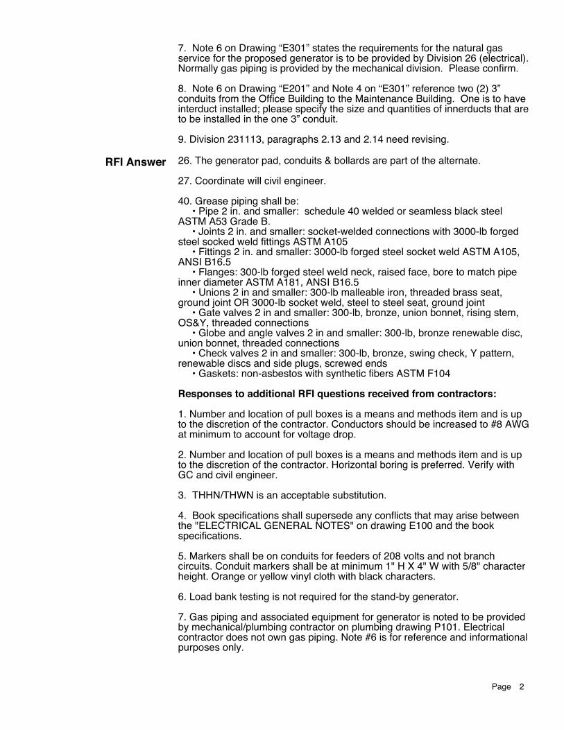
7. Note 6 on Drawing “E301” states the requirements for the natural gasservice for the proposed generator is to be provided by Division 26 (electrical).Normally gas piping is provided by the mechanical division. Please confirm.8. Note 6 on Drawing “E201” and Note 4 on “E301” reference two (2) 3”conduits from the Office Building to the Maintenance Building. One is to haveinterduct installed; please specify the size and quantities of innerducts that areto be installed in the one 3” conduit.9. Division 231113, paragraphs 2.13 and 2.14 need revising.
26. The generator pad, conduits & bollards are part of the alternate.27. Coordinate will civil engineer.40. Grease piping shall be: • Pipe 2 in. and smaller: schedule 40 welded or seamless black steelASTM A53 Grade B. • Joints 2 in. and smaller: socket-welded connections with 3000-lb forgedsteel socked weld fittings ASTM A105 • Fittings 2 in. and smaller: 3000-lb forged steel socket weld ASTM A105,ANSI B16.5 • Flanges: 300-lb forged steel weld neck, raised face, bore to match pipeinner diameter ASTM A181, ANSI B16.5 • Unions 2 in and smaller: 300-lb malleable iron, threaded brass seat,ground joint OR 3000-lb socket weld, steel to steel seat, ground joint • Gate valves 2 in and smaller: 300-lb, bronze, union bonnet, rising stem,OS&Y, threaded connections • Globe and angle valves 2 in and smaller: 300-lb, bronze renewable disc,union bonnet, threaded connections • Check valves 2 in and smaller: 300-lb, bronze, swing check, Y pattern,renewable discs and side plugs, screwed ends • Gaskets: non-asbestos with synthetic fibers ASTM F104Responses to additional RFI questions received from contractors:1. Number and location of pull boxes is a means and methods item and is upto the discretion of the contractor. Conductors should be increased to #8 AWGat minimum to account for voltage drop.2. Number and location of pull boxes is a means and methods item and is upto the discretion of the contractor. Horizontal boring is preferred. Verify withGC and civil engineer.3. THHN/THWN is an acceptable substitution.4. Book specifications shall supersede any conflicts that may arise betweenthe "ELECTRICAL GENERAL NOTES" on drawing E100 and the bookspecifications.5. Markers shall be on conduits for feeders of 208 volts and not branchcircuits. Conduit markers shall be at minimum 1" H X 4" W with 5/8" characterheight. Orange or yellow vinyl cloth with black characters.6. Load bank testing is not required for the stand-by generator.7. Gas piping and associated equipment for generator is noted to be providedby mechanical/plumbing contractor on plumbing drawing P101. Electrical contractor does not own gas piping. Note #6 is for reference and informationalpurposes only.
RFI Answer
2Page
8. Provide two 1" interducts in the 3" conduit indicated to have interductinstalled within.9. Revise Division 231113 to meet the following. Delete requirement for API650 in paragraph 2.13 B. and add requirements for UL58 and UL 1746. Deleteparagraph 2.13. E. completely. Delete requirement for UL80 in paragraph 2.14B. and add requirement for UL142.
3Page
TCC/SHORE TRANSIT BUS MAINTENANCE FACILITY - PHASE II 2009145.00
ALTERNATES 012300 - 1
SECTION 012300 - ALTERNATES
PART 1 - GENERAL
1.1 RELATED DOCUMENTS
A. Drawings and general provisions of the Contract, including General and Supplementary Conditions and other Division 01 Specification Sections, apply to this Section.
1.2 SUMMARY
A. This Section includes administrative and procedural requirements for alternates.
1.3 DEFINITIONS
A. Alternate: An amount proposed by bidders and stated on the Bid Form for certain work defined in the Bidding Requirements that may be added to or deducted from the Base Bid amount if Owner decides to accept a corresponding change either in the amount of construction to be completed or in the products, materials, equipment, systems, or installation methods described in the Contract Documents.
1. The cost or credit for each alternate is the net addition to or deduction from the Contract Sum to incorporate alternate into the Work. No other adjustments are made to the Contract Sum.
1.4 PROCEDURES
A. Coordination: Modify or adjust affected adjacent work as necessary to completely integrate work of the alternate into Project.
1. Include as part of each alternate, miscellaneous devices, accessory objects, and similar items incidental to or required for a complete installation whether or not indicated as part of alternate.
B. Notification: Immediately following award of the Contract, notify each party involved, in writing, of the status of each alternate. Indicate if alternates have been accepted, rejected, or deferred for later consideration. Include a complete description of negotiated modifications to alternates.
C. Execute accepted alternates under the same conditions as other work of the Contract. Accepted alternates will be executed at the same time as all other aspects of the work of the Contract except as noted.
D. Schedule: A Schedule of Alternates is included at the end of this Section. Specification Sections referenced in schedule contain requirements for materials necessary to achieve the work described under each alternate.
TCC/SHORE TRANSIT BUS MAINTENANCE FACILITY - PHASE II 2009145.00
ALTERNATES 012300 - 2
PART 2 - PRODUCTS (Not Used)
PART 3 - EXECUTION
3.1 SCHEDULE OF ALTERNATES
A. Alternate No. 1: Provide Metal Halide Exterior Lighting in lieu of LED Fixtures specified.
1. Provide and install metal halide lighting system and controls as noted on Drawing E-302 Site Lighting Fixture Schedule instead of LED fixtures and controls specified as base bid in same schedule.
B. Alternate No. 2: Emergency Generator
1. Provide an emergency generator as defined by the contract documents as Add/Alt#2.
C. Alternate No. 3: Delete Gas-fired Infrared Heaters from Base Bid Contract Documents
1. Provide No gas fired infrared heaters, gas piping to infrared heaters, or electrical connections are required. Gas piping will be caped and circuit breakers will become spares.
D. Alternate No. 4: Wash Bay Addition
1. Provide Additional Building area at Wash Bay 126 as defined by the contract documents as Add/Alt#4.
E. Alternate No.5: Fuel Depot
1. Provide fuel tanks, fuel dispensers, canopy, fuel monitoring system and all equipment and permits necessary to have a functioning fuel depot permitted by the State of Maryland to provide fuel to the Shore Transit fleet in accordance with the contract documents as Add Alternate #5.
2. Within the lump sum price for this Alternate include all site work as indicated on sheet C-304 and associated Detail sheets for construction of the Fuel station and storage areas. Include grading, stone base, concrete paving, dispenser Island, striping, curb with or without gutter, stormdrain pipe & fittings, catch basins, cleanouts, oil water separator complete and other underground components.
F. Alternate No.6: Asphalt Paving of Rear Bus Lot.
1. Provide heavy duty asphalt surface paving for the gravel bus parking lot on the west end of the site. Construct the parking lot to the design grades shown in the base bid with the Heavy Duty Asphalt paving section shown on the contract documents as identified as Add Alternate No. 6.
TCC/SHORE TRANSIT BUS MAINTENANCE FACILITY - PHASE II 2009145.00
ALTERNATES 012300 - 3
G. Alternate No. 7: Prefabricated Metal Walkway Cover at Existing Multipurpose Center
1. Provide prefabricated metal walkway cover, foundation and associated lighting, flashing and underground drainage at existing multipurpose center building as defined by the contract documents as Add/Alt#7.
H. Alternate No. 8: Flexible Asphalt Paving in lieu of Concrete Rigid Paving
1. Provide bituminous pavement in roadway and parking lot as indicated on Sheet C-603 in lieu of concrete pavement. Pavement will consist of both heavy duty sections and light duty sections in quantities indicated on Sheet C-603. Alternate includes transitions (Tie-in Details) as shown on sheet C-603.
I. Alternate No. 9: Enlarge Fire Water Main
1. Provide 8”/4” C900 PVC Fire Water Main and all fittings, valves and appurtenances as shown on sheet C-305 in lieu of 4” main as shown on the base bid drawings. Also, delete 2½” domestic water line shown on base bid and install 3” / 2½” line as shown in Alternate 9 on sheet C-305.
J. Alternate No 10: Epoxy floor at Service Bays
1. Provide Stonhard, Inc.; Stonclad GS with Stonkote GS4 or approved equivalent at service bay floors in lieu of sealed concrete floor finish as noted on finish schedule on sheet A601 & spec section 096723.
K. Alternate No 11: Double Wall Oil/Water Separator
1. Provide a double wall oil/water separator tank in lieu of a single wall tank (Sheet reference C-304). Highland Tank model number 05000HGDWHTCG or approved equal. Price shall reflect the difference in cost from the single wall to the double wall tank.
L. Alternate No. 12: Face Brick at Bus Maintenance Building
1. Provide face brick by manufacturer other than the basis of design “ Belden Brick Company ” listed in spec section 042000-2.5-B-3 .
2. Alternate brick manufacturer to meet all product criteria listed in spec sections 042000-2.1-A, 042000-2.5-A-1 & 2, 042000-2.5-B-1 & 2. Current test data required for all proposed materials.
3. Alternate face brick to meet the following finish/color requirements (as well those listed above)
a. Face Brick Type A - Taylor Clay Products #3-9 Dark Brown Ironspot. (actual
dimensions to be 3 5/8” wide by 3 5/8” high by 16” long) b. Face Brick Type B - Taylor Clay Products #301-W White. (actual dimensions to
be 3 5/8” wide by 3 5/8” high by 16” long)
TCC/SHORE TRANSIT BUS MAINTENANCE FACILITY - PHASE II 2009145.00
ALTERNATES 012300 - 4
c. Face Brick Type C – Glazed Black Brick by Taylor Clay or other equivalent
manufacturer (actual dimensions to be 3 5/8” wide by 3 5/8” high by 16” long)
4. Alternates by Glen Gehry and Endicott Clay may be considered by the architect. Must submit material sample and product data with test results and certifications consistent with requirements in spec section 042000-1.4 & 042000-1.5.
END OF SECTION 012300
TCC/SHORE TRANSIT BUS MAINTENANCE FACILITY - PHASE II 2009145.00
BID FORM 003000 - 1
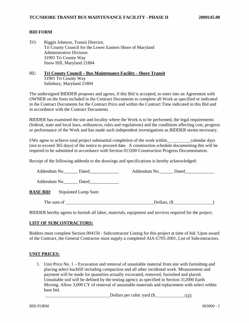
BID FORM TO: Riggin Johnson, Transit Director, Tri County Council for the Lower Eastern Shore of Maryland Administrative Division 31901 Tri County Way Snow Hill, Maryland 21804 RE: Tri County Council – Bus Maintenance Facility - Shore Transit 31901 Tri County Way Salisbury, Maryland 21804 The undersigned BIDDER proposes and agrees, if this Bid is accepted, to enter into an Agreement with OWNER on the form included in the Contract Documents to complete all Work as specified or indicated in the Contract Documents for the Contract Price and within the Contract Time indicated in this Bid and in accordance with the Contract Documents. BIDDER has examined the site and locality where the Work is to be performed, the legal requirements (federal, state and local laws, ordinances, rules and regulations) and the conditions affecting cost, progress or performance of the Work and has made such independent investigations as BIDDER seems necessary. I/We agree to achieve total project substantial completion of the work within calendar days (not to exceed 365 days) of the notice to proceed date. A construction schedule documenting this will be required to be submitted in accordance with Section 013200 Construction Progress Documentation. Receipt of the following addenda to the drawings and specifications is hereby acknowledged:
BIDDER hereby agrees to furnish all labor, materials, equipment and services required for the project. LIST OF SUBCONTRACTORS: Bidders must complete Section 004150 - Subcontractor Listing for this project at time of bid. Upon award of the Contract, the General Contractor must supply a completed AIA G705-2001, List of Subcontractors. UNIT PRICES:
1. Unit Price No. 1 – Excavation and removal of unsuitable material from site with furnishing and placing select backfill including compaction and all other incidental work. Measurement and payment will be made for quantities actually excavated, removed, furnished and placed. Unsuitable soil will be defined by the testing agency as specified in Section 312000 Earth Moving. Allow 3,000 CY of removal of unsuitable materials and replacement with select within base bid.
Dollars per cubic yard ($ /cy)
TCC/SHORE TRANSIT BUS MAINTENANCE FACILITY - PHASE II 2009145.00
BID FORM 003000 - 2
2. Unit Price No. 2 – Construct Heavy Duty Rigid Concrete Pavement per the paving section shown on the contract documents. Price includes furnishing and placing required materials including compaction, grading, finishing and all other incidental work. Measurement and payment will be made for quantities actually furnished and placed per square yard.
Dollars per square yard ($ /sy)
3. Unit Price No. 3 – Construct 6” Curb and Gutter per the construction details on the contract documents. Price includes furnishing and placing required materials including stakeout, grading, finishing and all other incidental work. Measurement and payment will be made for quantities actually furnished and placed per lineal foot.
Dollars per lineal foot ($ /lf)
4. Unit Price No. 4 – Construct 3’ wide Concrete Vee Gutter per the construction details on the contract documents. Price includes furnishing and placing required materials including stakeout, grading, finishing and all other incidental work. Measurement and payment will be made for quantities actually furnished and placed per lineal foot.
Dollars per lineal foot ($ /lf)
5. Unit Price No. 5 – Mill existing asphalt paving to a depth of 1.5” and overlay with 2” of hot-mix asphalt paving. Paving mix shall be Superpave PG 76-22, 12.5 mm, level 2, 65 gyrations. Allowable RAP content = 15-20%. Price includes disposal of wasted materials, furnishing and placing required materials including stakeout, grading, finishing and all other incidental work. Measurement and payment will be made for quantities actually furnished and placed per square yard.
Dollars per square yard ($ /sy) ALTERNATE NO. 1: Provide Metal Halide Exterior Lighting in lieu of LED Fixtures specified.
1. Provide and install metal halide lighting system and controls as noted on Drawing E-302 Site
Lighting Fixture Schedule instead of LED fixtures and controls specified as base bid in same schedule.
ADD Dollars, ($ )
ALTERNATE NO. 2: Emergency Generator
1. Provide an emergency generator as defined by the contract documents as Add/Alt#2. ADD Dollars, ($ )
ALTERNATE NO. 3: Delete Gas-fired Infrared Heaters from Base Bid Contract Documents
1. Provide No gas fired infrared heaters, gas piping to infrared heaters, or electrical connections are required. Gas piping will be caped and circuit breakers will become spares.
DELETE Dollars, ($ )
ALTERNATE NO. 4 : Wash Bay Addition
1. Provide Additional Building area at Wash Bay 126 as defined by the contract documents as Add/Alt#4.
TCC/SHORE TRANSIT BUS MAINTENANCE FACILITY - PHASE II 2009145.00
BID FORM 003000 - 3
ADD Dollars, ($ )
ALTERNATE NO. 5 : Fuel Depot
1. Provide fuel tanks, fuel dispensers, canopy, fuel monitoring system and all equipment and permits necessary to have a functioning fuel depot permitted by the State of Maryland to provide fuel to the Shore Transit fleet in accordance with the contract documents as Add Alternate #5.
ADD Dollars, ($ )
ALTERNATE NO. 6 : Asphalt Paving of Rear Bus Lot.
1. Provide heavy duty asphalt surface paving for the gravel bus parking lot on the west end of the site. Construct the parking lot to the design grades shown in the base bid with the Heavy Duty Asphalt paving section shown on the contract documents as identified as Add Alternate No. 6
ADD Dollars, ($ )
ALTERNATE NO. 7 : Prefabricated Metal Walkway Cover at Existing Multipurpose Center
1. Provide prefabricated metal walkway cover, foundation and associated lighting, flashing and underground drainage at existing multipurpose center building as defined by the contract documents as Add/Alt#7.
ADD Dollars, ($ )
ALTERNATE NO. 8 : Flexible Asphalt Paving in lieu of Concrete Rigid Paving 1. Provide bituminous pavement in roadway and parking lot as indicated on Sheet C-603 in lieu of concrete pavement. Pavement will consist of both heavy duty sections and light duty sections in quantities indicated on Sheet C-603. Alternate includes transitions (Tie-in Details) as shown on sheet C-603.
ADD Dollars, ($ )
ALTERNATE NO. 9 : Enlarge Fire Water Main 1. Provide 8” C900 PVC Fire Water Main in lieu of 4” main as shown on sheet C-305.
ADD Dollars, ($ )
ALTERNATE NO. 10 : Epoxy floor at service bays 1. Provide Stonhard, Inc.; Stonclad GS with Stonkote GS4 or approved equivalent at service bay floors in lieu of sealed concrete floor finish as noted on finish schedule on sheet A601.
TCC/SHORE TRANSIT BUS MAINTENANCE FACILITY - PHASE II 2009145.00
BID FORM 003000 - 4
1. Provide a double wall oil/water separator tank in lieu of a single wall tank (Sheet reference C-304). Highland Tank model number 05000HGDWHTCG or approved equal. Price shall reflect the difference in cost from the single wall to the double wall tank.
ADD Dollars, ($ )
ALTERNATE NO. 12 : Alternate No. 12: Face Brick at Bus Maintenance Building
1. Provide Face Brick as noted in spec. section. 012300-3.1-L
ADD Dollars, ($ )
ALLOWANCE NO. 1 : Lump-Sum Allowance: Include the sum of $15,000.00 for furnishing and installing all materials necessary for completion of the irrigation system.
1. This allowance includes material cost, receiving, handling, and installation, and Contractor
overhead and profit.
ALLOWANCE NO. 2 : Lump-Sum Allowance: Include the sum of $50,000 for furnishing and installing all materials necessary for completion of a 1,800 sq ft pole building
1. This allowance includes material cost, receiving, handling, and installation, and Contractor overhead and profit.
In submitting this bid we agree: 1. This offer is binding and cannot be withdrawn until ninety (90) days from date of Bid. 2. To accept the provisions of Instructions to Bidders. 3. To enter into and execute a contract, if awarded on the basis of this Bid, and to furnish performance
and payment bonds in accordance with the Instructions to Bidders and Supplementary Conditions. 4. To accomplish the Work in accordance with the Contract Documents. 5. Owner will award based on review of lowest responsive and responsible bidder based on alternates,
submitted proposed substantial completion date and bidders qualification. 6. All subcontractors or suppliers furnishing over $100,000 in combined labor and material are
bondable. 7. Add/Alternate pricing to be held for (90) days from date of Bid. Owner will review base bids from responsive bidders, submitted proposed substantial completion dates and bidders’ qualifications. Owner will make the award based on his best interests. We have attached the required bid security to this bid.
(1) Signature when Bidder is an individual: Respectfully submitted, _____________ _____________________________
TCC/SHORE TRANSIT BUS MAINTENANCE FACILITY - PHASE II 2009145.00
BID FORM 003000 - 5
Date Firm Name _____________________________ Owner
(2) Signature when Bidder is a partnership: _____________________________ _____________ Firm Name Date
_____________________________ Signature of Partner
_____________________________ Signature of Partner
_____________________________ Signature of Partner
(3) Signature when Bidder is a Corporation: _____________________________ _____________ Firm Name Date By___________________________
_____________________________ Corporate Seal Title
TCC/SHORE TRANSIT BUS MAINTENANCE FACILITY - PHASE II 2009145.00
BID FORM 003000 - 6
NON-COLLUSION STATEMENT The Bidder hereby attests that he has not conspired with any other party in an attempt to bid a fixed or set price.
SUBSCRIBED AND SWORN to, and before me, a Notary Public,
of the State of _________________________________________
County of/City of ______________________________________
Signed:
Title:_______________________ Notary Public
This _________ day of ______________________, 2012
Maryland Contractor’s License #____________ Federal EI #________________
THIS PAGE MUST BE SIGNED AND NOTARIZED FOR YOUR BID TO BE CONSIDERED.
TCC/SHORE TRANSIT BUS MAINTENANCE FACILITY - PHASE II 2009145.00
BID FORM 003000 - 7
BUY AMERICA CERTIFICATION
Contractor is to complete one of the sections below and submit with their bid. Certificate of Compliance with 49 U.S.C. 5323(j)(1) The bidder or offeror hereby certifies that it will meet the requirements of 49 U.S.C. 5323(j)(1) and the applicable regulations in 49 C.F.R. Part 661.5. Date _______________________________________________________________________________ Signature ____________________________________________________________________________ Company Name ______________________________________________________________________ Title _______________________________________________________________________________ or Certificate of Non-Compliance with 49 U.S.C. 5323(j)(1) The bidder or offeror hereby certifies that it cannot comply with the requirements of 49 U.S.C. 5323(j)(1) and 49 C.F.R. 661.5, but it may qualify for an exception pursuant to 49 U.S.C. 5323(j)(2)(A), 5323(j)(2)(B), or 5323(j)(2)(D), and 49 C.F.R. 661.7. Date _______________________________________________________________________________ Signature ___________________________________________________________________________ Company Name ______________________________________________________________________ Title _______________________________________________________________________________
TCC/SHORE TRANSIT BUS MAINTENANCE FACILITY - PHASE II 2009145.00
BID FORM 003000 - 8
CERTIFICATION REGARDING LOBBYING APPENDIX A, 49 CFR PART 20 Certification for Contracts, Grants, Loans, and Cooperative Agreements (To be submitted with each bid or offer exceeding $100,000) The undersigned certifies, to the best of his or her knowledge and belief, that: (1) No Federal appropriated funds have been paid or will be paid, by or on behalf of the undersigned, to any person for influencing or attempting to influence an officer or employee of an agency, a Member of Congress, an officer or employee of Congress, or an employee of a Member of Congress in connection with the awarding of any Federal contract, the making of any Federal grant, the making of any Federal loan, the entering into of any cooperative agreement, and the extension, continuation, renewal, amendment, or modification of any Federal contract, grant, loan, or cooperative agreement. (2) If any funds other than Federal appropriated funds have been paid or will be paid to any person for making lobbying contacts to an officer or employee of any agency, a Member of Congress, an officer or employee of Congress, or an employee of a Member of Congress in connection with this Federal contract, grant, loan, or cooperative agreement, the undersigned shall complete and submit Standard Form--LLL, "Disclosure Form to Report Lobbying," in accordance with its instructions [as amended by "Government wide Guidance for New Restrictions on Lobbying," 61 Fed. Reg. 1413 (1/19/96). Note: Language in paragraph (2) herein has been modified in accordance with Section 10 of the Lobbying Disclosure Act of 1995 (P.L. 104-65, to be codified at 2 U.S.C. 1601, et seq.)] (3) The undersigned shall require that the language of this certification be included in the award documents for all subawards at all tiers (including subcontracts, subgrants, and contracts under grants, loans, and cooperative agreements) and that all subrecipients shall certify and disclose accordingly. This certification is a material representation of fact upon which reliance was placed when this transaction was made or entered into. Submission of this certification is a prerequisite for making or entering into this transaction imposed by 31, U.S.C. § 1352 (as amended by the Lobbying Disclosure Act of 1995). Any person who fails to file the required certification shall be subject to a civil penalty of not less than $10,000 and not more than $100,000 for each such failure. [Note: Pursuant to 31 U.S.C. § 1352(c)(1)-(2)(A), any person who makes a prohibited expenditure or fails to file or amend a required certification or disclosure form shall be subject to a civil penalty of not less than $10,000 and not more than $100,000 for each such expenditure or failure.] The Contractor, ___________________, certifies or affirms the truthfulness and accuracy of each statement of its certification and disclosure, if any. In addition, the Contractor understands and agrees that the provisions of 31 U.S.C. A 3801, et seq., apply to this certification and disclosure, if any. __________________________ Signature of Contractor's Authorized Official __________________________ Name and Title of Contractor's Authorized Official ___________________________ Date
TCC/SHORE TRANSIT BUS MAINTENANCE FACILITY - PHASE II 2009145.00
BID FORM 003000 - 9
SIMILAR PROJECT EXPEREINCE
Provide a minimum of three similar projects. Each project listing should include the following information: Project name, Owner, Architect, Contract Amount, Date of Completion, and percentage of work completed by your forces. END OF BID FORM
096700-1 PROJECT NO. XXXX RESINOUS FLOORING
SECTION 09 67 24 - RESINOUS FLOORING (2)
PART 1 - GENERAL
1.1 RELATED DOCUMENTS
A. Drawings and general provisions of the Contract, including General and Supplementary Conditions and Division 01 Specification Sections, apply to this Section.
1.2 SUMMARY
A. This Section includes one resinous flooring system, with three component Troweled mortar.
1. Products: Subject to compliance with requirements:
a. Stonhard, Inc.; Stonclad GS with Stonkote GS4.
1.3 SUBMITTALS
A. Product Data: For each type of product indicated. Include manufacturer's technical data, application instructions, and recommendations for each resinous flooring component required.
B. Samples for Verification: For each resinous flooring system required, 6 inches (150 mm) square, applied to a rigid backing by Installer for this Project.
C. Product Schedule: Use resinous flooring designations indicated in Part 2 and room designations indicated on Drawings in product schedule.
D. Installer Certificates: Signed by manufacturer certifying that installers comply with specified requirements.
E. Maintenance Data: For resinous flooring to include in maintenance manuals.
1.4 QUALITY ASSURANCE
A. Installer Qualifications: Engage an experienced installer (applicator) who is experienced in applying resinous flooring systems similar in material, design, and extent to those indicated for this Project, whose work has resulted in applications with a record of successful in-service performance, and who is acceptable to resinous flooring manufacturer. 1. Engage an installer who is certified in writing by resinous flooring manufacturer
as qualified to apply resinous flooring systems indicated. 2. Contractor shall have completed at least 10 projects of similar size and
complexity.
B. Source Limitations: Obtain primary resinous flooring materials, including primers, resins, water proofing membranes, hardening agents, grouting coats, broadcast
096700 RESINOUS FLOORING PROJECT NO. XXXXX
aggregates and topcoats through one source from a single manufacturer, with not less than ten years of successful experience in manufacturing and installing principal materials described in this section. Provide secondary materials, including patching and fill material, joint sealant, and repair materials, of type and from source recommended by manufacturer of primary materials.
C. Manufacturer Field Technical Service Representatives: Resinous flooring manufacture shall retain the services of Field Technical Service Representatives who are trained specifically on installing the system to be used on the project.
1. Field Technical Services Representatives shall be employed by the system manufacture to assist in the quality assurance and quality control process of the installation and shall be available to perform field problem solving issues with the installer.
D. Mockups: Apply mockups to verify selections made under sample submittals and to demonstrate aesthetic effects and set quality standards for materials and execution.
1. Apply full-thickness mockups on 48-inch- (1200-mm-) square floor area selected by Architect.
1. Include 48-inch (1200-mm) length of integral cove base.
2. Approved mockups may become part of the completed Work if undisturbed at time of Substantial Completion.
E. Pre-installation Conference:
1. General contractor shall arrange a meeting not less than thirty days prior to starting work.
2. Attendance:
1. General Contractor
2. Architect/Owner's Representative.
3. Resinous Manufacture.
1.5 DELIVERY, STORAGE, AND HANDLING
A. Deliver materials in original packages and containers, with seals unbroken, bearing manufacturer's labels indicating brand name and directions for storage and mixing with other components.
B. Store materials to prevent deterioration from moisture, heat, cold, direct sunlight, or other detrimental effects.
C. All materials used shall be factory pre-weighed and pre-packaged in single, easy to manage batches to eliminate on site mixing errors. No on site weighing or volumetric measurements allowed.
096700-3 PROJECT NO. XXXX RESINOUS FLOORING
1.6 PROJECT CONDITIONS
A. Environmental Limitations: Comply with resinous flooring manufacturer's written instructions for substrate temperature, ambient temperature, moisture, ventilation, and other conditions affecting resinous flooring application.
1. Maintain material and substrate temperature between 65 and 85 deg F (18 and 30 deg C) during resinous flooring application and for not less than 24 hours after application.
B. Lighting: Provide permanent lighting or, if permanent lighting is not in place, simulate permanent lighting conditions during resinous flooring application.
C. Close spaces to traffic during resinous flooring application and for not less than 24 hours after application, unless manufacturer recommends a longer period.
D. Type 1 concrete substrate shall be properly cured for a minimum of 30 days. A vapor barrier must be present for concrete subfloors on or below grade. If a vapor barrier is not present please consult with your Stonhard technical representative.
1.7 WARRANTY
A. Manufacturer shall furnish a single, written warranty covering both material and workmanship for a period of (1) full years from date of installation, or provide a joint and several warranty signed on a single document by material manufacturer and applicator jointly and severally warranting the materials and workmanship for a period of (1) full year from date of installation. A sample warranty letter must be included with bid package or bid may be disqualified.
PART 2 - PRODUCTS
2.1 RESINOUS FLOORING
A. RESINOUS FLOORING SYSTEM #1 (RES-1)
1. Stonclad GS with Stonkote GS4 epoxy topcoat as manufactured by Stonhard,
Inc., Maple Shade, NJ, Bob Stein (800) 257-7953 is a nominal 1/4"/6mm thick system comprised of a penetrating, moisture tolerant, two-component epoxy primer, a high performance, three-component mortar consisting of epoxy resin, curing agent and selected, graded aggregates blended with inorganic pigments and a two-component, 100% solids, epoxy coating.
2. Acceptable Equivalents: Request for materials approvals for any products other than the specified product must be submitted to the architect no later than two weeks prior to project bid date. Any request after this date will not be accepted.
3. Available Products: Build up of Broadcast or liquid rich (slurry) type systems will
not be accepted, and will result in a disqualification from bid.
096700 RESINOUS FLOORING PROJECT NO. XXXXX
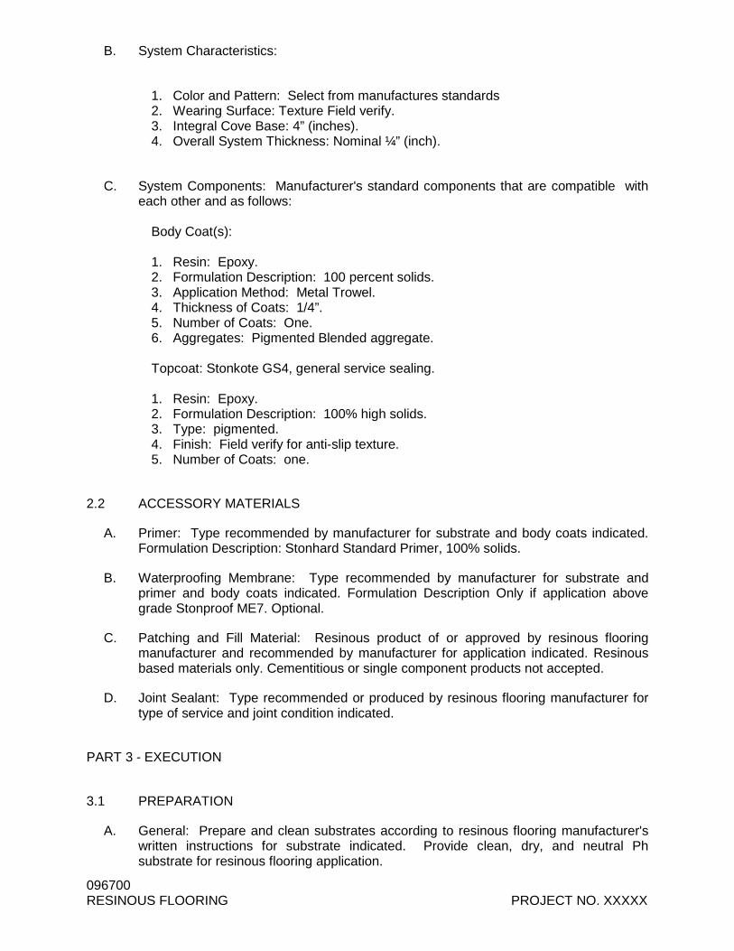
B. System Characteristics:
1. Color and Pattern: Select from manufactures standards 2. Wearing Surface: Texture Field verify. 3. Integral Cove Base: 4” (inches). 4. Overall System Thickness: Nominal ¼” (inch).
C. System Components: Manufacturer's standard components that are compatible with each other and as follows:
Body Coat(s): 1. Resin: Epoxy. 2. Formulation Description: 100 percent solids. 3. Application Method: Metal Trowel. 4. Thickness of Coats: 1/4”. 5. Number of Coats: One. 6. Aggregates: Pigmented Blended aggregate. Topcoat: Stonkote GS4, general service sealing. 1. Resin: Epoxy. 2. Formulation Description: 100% high solids. 3. Type: pigmented. 4. Finish: Field verify for anti-slip texture. 5. Number of Coats: one.
2.2 ACCESSORY MATERIALS
A. Primer: Type recommended by manufacturer for substrate and body coats indicated. Formulation Description: Stonhard Standard Primer, 100% solids.
B. Waterproofing Membrane: Type recommended by manufacturer for substrate and primer and body coats indicated. Formulation Description Only if application above grade Stonproof ME7. Optional.
C. Patching and Fill Material: Resinous product of or approved by resinous flooring manufacturer and recommended by manufacturer for application indicated. Resinous based materials only. Cementitious or single component products not accepted.
D. Joint Sealant: Type recommended or produced by resinous flooring manufacturer for type of service and joint condition indicated.
PART 3 - EXECUTION
3.1 PREPARATION
A. General: Prepare and clean substrates according to resinous flooring manufacturer's written instructions for substrate indicated. Provide clean, dry, and neutral Ph substrate for resinous flooring application.
096700-5 PROJECT NO. XXXX RESINOUS FLOORING
B. Concrete Substrates: Provide sound concrete surfaces free of laitance, glaze, efflorescence, curing compounds, form-release agents, dust, dirt, grease, oil, and other contaminants incompatible with resinous flooring.
C. Mechanically prepare substrates as follows:
1. Includes use of a scabbler, scarifier or shot blast machine for removal of
bond inhibiting materials such as curing compounds or laitance. 2. Hand diamond grind near walls and obstructions. 3. Comply with ASTM C 811 requirements, unless manufacturer's written
instructions are more stringent. 4. Repair damaged and deteriorated concrete according to resinous flooring
manufacturer's written recommendations. 5. Consider including allowance or unit price for remedial procedures if
concrete substrates exhibit unacceptable moisture-vapor-emission rates. See "Moisture and Flooring Failures" Article in the Evaluations.
D. Verify that concrete substrates are dry.
1. Perform in situ probe test, ASTM F 2170. Proceed with application only after substrates do not exceed a maximum potential equilibrium relative humidity of 85 percent.
2. Perform additional moisture tests recommended by manufacturer. Proceed with application only after substrates pass testing.
3. Verify that concrete substrates have neutral Ph and that resinous flooring will adhere to them. Perform tests recommended by manufacturer. Proceed with application only after substrates pass testing.
E. Resinous Materials: Mix components and prepare materials according to resinous flooring manufacturer's written instructions.
F. Use patching and fill material to fill holes and depressions in substrates according to manufacturer's written instructions.
G. Treat control joints and other nonmoving substrate cracks to prevent cracks from reflecting through resinous flooring according to manufacturer's written recommendations.
3.2 APPLICATION
A. General: Apply components of resinous flooring system according to manufacturer's written instructions to produce a uniform, monolithic wearing surface of thickness indicated.
1. Coordinate application of components to provide optimum adhesion of resinous flooring system to substrate, and optimum intercoat adhesion.
2. Cure resinous flooring components according to manufacturer's written instructions. Prevent contamination during application and curing processes.
3. At substrate expansion and isolation joints, provide joint in resinous flooring to comply with resinous flooring manufacturer's written recommendations.
1. Apply joint sealant to comply with manufacturer's written recommendations.
096700 RESINOUS FLOORING PROJECT NO. XXXXX
B. Apply primer where required by resinous system, over prepared substrate at manufacturer's recommended spreading rate.
A. Integral Cove Base: Stonclad GS epoxy troweled mortar. Apply according to manufacturer's written instructions and details including those for taping, mixing, priming, troweling, sanding, and topcoating of cove base. Round internal and external corners.
1. Integral Cove Base: 4” (inches) high.
B. Apply metal trowel single mortar coat in thickness indicated for flooring system. Hand or power trowel and grout to fill voids. When cured, sand to remove trowel marks and roughness.
C. Apply base coats and topcoats in number of coats indicated for flooring system and at spreading rates recommended in writing by manufacturer.
3.3 FIELD QUALITY CONTROL
A. Material Sampling: Owner may at any time and any numbers of times during resinous flooring application require material samples for testing for compliance with requirements.
1. Owner will engage an independent testing agency to take samples of materials being used. Material samples will be taken, identified, sealed, and certified in presence of Contractor.
2. Testing agency will test samples for compliance with requirements, using applicable referenced testing procedures or, if not referenced, using testing procedures listed in manufacturer's product data.
3. If test results show applied materials do not comply with specified requirements, pay for testing, remove noncomplying materials, prepare surfaces coated with unacceptable materials, and reapply flooring materials to comply with requirements.
3.4 CLEANING, PROTECTING, AND CURING
A. Cure resinous flooring materials in compliance with manufacturer's directions, taking care to prevent contamination during stages of application and prior to completion of curing process. Close area of application for a minimum of 24 hours.
B. Protect resinous flooring materials from damage and wear during construction operation. Where temporary covering is required for this purpose, comply with manufacturer's recommendations for protective materials and method of application. General Contractor is responsible for protection and cleaning of surfaces after final coats.
C. Cleaning: Remove temporary covering and clean resinous flooring just prior to final inspection. Use cleaning materials and procedures recommended by resinous flooring manufacturer
END OF SECTION 096723
TCC/SHORE TRANSIT BUS MAINTENANCE FACILITY - PHASE II 2009145.00
METAL EVIDENCE LOCKER 105113-1
SECTION 105113 – METAL EVIDENCE LOCKERS (STANDARD A ND REFRIGERATED, PASS-THRU AND NON-PASS-THRU.)
PART 1 - GENERAL
1.1 RELATED DOCUMENTS
A. Drawings and general provisions of the Contract, including General and Supplementary Conditions and Division 1 Specification Sections, apply to this Section.
1.2 SUMMARY
A. This Section includes the following:
Standard and Refrigerated Pass-thru and Non Pass-thru Evidence Lockers
B. Related Work, Not Furnished:
Finish floor covering materials and installation.
C. Related Sections:
[Sections in Division 9 – Finishes, relating to finish floor and base materials.]
D. Allowances:
E. Alternates:
1.3 REFERENCES
A. American National Standards Institute (ANSI) Standards:
Applicable standards for fasteners used for assembly.
B. American Society for Testing and Materials (ASTM) Standards:
Applicable standards for steel sheet materials used for fabrication.
Applicable standards for the testing of electrostatically applied Powder Coat Paint
C. American Institute Of Steel Construction (AISC) Standards:
Applicable standards for steel materials used for fabrication.
1.4 DESCRIPTION
A. General: Metal Evidence Lockers
B. Finishes:
Fabricated Metal Components and Assemblies: All components to be painted with an electrostatically applied Powder Coat paint that can meet or exceed test requirements set out by ASTM standard D3451-06 Standard Guide for Testing Coating Powders and Powder Coatings.
TCC/SHORE TRANSIT BUS MAINTENANCE FACILITY - PHASE II 2009145.00
METAL EVIDENCE LOCKER 105113-2
C. Sizes:
Available in a nominal height of [82] inches ([2,083MM])
Available in nominal widths of [24] [36] inches ([609MM] [914MM]) as noted on drawings.
Available in a nominal depth of [24] inches ([609MM]) as noted on drawings.
1.5 PERFORMANCE REQUIREMENTS
A. Design Requirements:
Limit overall width to [0.032] inches [0.793MM] greater or less than the nominal specified width.
B. [Seismic Performance: Provide Metal Evidence lockers capable of withstanding the effects of earthquake movement when required by applicable building codes.]
1.6 SUBMITTALS
A. Product Data: Submit manufacturer's product literature and installation instructions for each type of evidence lockers required. Include data substantiating that products to be furnished comply with requirements of the contract documents.
B. Shop Drawings: Show fabrication, assembly, and installation details including descriptions of procedures and diagrams. Show complete extent of evidence lockers installation layout including quantities, locations and types of accessory units required. Include notations and descriptions of all installation items and components.
Show installation details at non-standard conditions, if any.
Provide layout, dimensions, and identification of each unit corresponding to sequence of installation procedures.
Provide installation schedule and procedures to ensure proper installation.
C. Samples: Provide minimum 3 inch (76MM) square example of each color and texture on actual substrate for each component to remain exposed after installation.
D. Selection Samples: For initial selection of colors and textures, submit manufacturer's color charts consisting of actual product pieces, showing full range of colors and textures available.
E. Warranty: Submit draft copy of proposed warranty for review by the [Architect] [Architect/Engineer] [Engineer] [Designer].
F. Maintenance Data: provide written documentation of the manufacturer’s statement claiming the maintenance free nature of the product.
G. [Reference List: Provide a list of recently installed evidence lockers to be visited by owner, architect, and contractor. Intent of list is to aid in verifying the suitability of manufacturer's products and comparison with materials and product specified in this section.]
TCC/SHORE TRANSIT BUS MAINTENANCE FACILITY - PHASE II 2009145.00
METAL EVIDENCE LOCKER 105113-3
1.7 QUALITY ASSURANCE
A. Manufacturer Qualifications: Engage an experienced manufacturer who is ISO 9001 certified for the design, production, installation and service of evidence lockers. Furnish certification attesting ISO 9001 quality system registration.
B. Installer Qualifications: Engage an experienced installer who is a manufacturer's authorized representative for the specified products for installing evidence lockers.
Minimum Qualifications: 1-year experience installing evidence lockers of comparable size and complexity to specified project requirements.
1.8 DELIVERY, STORAGE AND HANDLING
A. Follow manufacturer’s instructions and recommendations for delivery, storage and handling requirements.
1.9 PROJECT CONDITIONS
A. Field Measurements: Verify quantities of evidence lockers before fabrication. Indicate verified measurements on Shop Drawings. Coordinate fabrication and delivery to ensure no delay in progress of the Work.
B. Established Dimensions: Where field measurements cannot be made without delaying the Work, establish dimensions and proceed with fabricating evidence lockers units without field measurements. Coordinate construction to ensure actual dimensions correspond to established dimensions.
1.10 [SEQUENCING AND SCHEDULING]
A. Sequence evidence lockers units [with other work] to minimize possibility of damage and soiling during remainder of construction period.
B. Schedule installation of specified evidence lockers after finishing operations; including painting have been completed.
C. Provide components which must be built in at a time which causes no delays general progress of the Work.
D. Pre-installation Conference: Schedule and conduct conference on project site to review methods and procedures for installing evidence lockers including, but not limited to the following:
Recommended attendees include:
1. Owner's Representative.
2. Prime Contractor or representative.
3. The [Architect] [Architect/Engineer] [Engineer/Architect] [Engineer] [Designer].
4. Manufacturer's representative.
5. Subcontractors or installers whose work may affect, or be affected by the work of this section.
TCC/SHORE TRANSIT BUS MAINTENANCE FACILITY - PHASE II 2009145.00
METAL EVIDENCE LOCKER 105113-4
1.11 WARRANTY
A. Provide a written warranty executed by Contractor, Installer and Manufacturer, agreeing to repair or replace units which fail in materials or workmanship within the established warranty period. This warranty shall be in addition to and not a limitation of other rights the Owner may have under the General Conditions provisions of the Contract Documents.
B. Limited Lifetime Warranty: Subject to the terms in the written warranty, warrant the original purchaser exclusively that the locker frames manufactured by it will be free from defects in materials and workmanship for the lifetime of the locker. Warrant the original purchaser exclusively that all moving parts manufactured by it will be free from defects in materials and workmanship for 5 years. Warrant the original purchaser exclusively that all electrical components manufactured by it will be free from defects in materials and workmanship for 4 years.
PART 2 - PRODUCTS
2.1 MANUFACTURERS
A. Basis-of-Design: DSM Evidence Lockers manufactured by Spacesaver Corporation, 1450 Janesville Avenue, Fort Atkinson, Wisconsin 53538-2798. Telephone 866-276-0445. or approved equivelent
2.2 BASIC MATERIALS
A. General: Provide materials and quality of workmanship, which meets or exceeds established industry standards for products specified. Use furniture grade sheet metal and fasteners for component fabrication unless indicated otherwise. Material thicknesses/gauges are manufacturer’s option unless indicated otherwise.
2.3 LOCKER TYPES
A. [Pass-thru evidence lockers]
B. [Non pass-thru evidence lockers]
C. [Pass-thru refrigerated evidence lockers]
D. [Non pass-thru refrigerated evidence lockers]
2.4 MANUFACTURED COMPONENTS, STANDARD EVIDENCE LOCKERS
A. Welded Frame:
1. The welded frame is structural and shall consist of top, bottom, back and sides constructed of a minimum of 18 gage (1.21MM) steel. All frame components shall be joined using resistance welding. Riveting or bolting of structural members will not be permitted.
2. Horizontal and vertical outer front flanges will be a minimum of 1.5 inches (38MM). Horizontal and vertical flanges will overlap with a minimum of 2 resistance welds per corner.
TCC/SHORE TRANSIT BUS MAINTENANCE FACILITY - PHASE II 2009145.00
METAL EVIDENCE LOCKER 105113-5
3. Center vertical lock housing is structural and will run the full height and depth of the locker. All locks will be completely enclosed by a full height removable panel. Pass-thru rear release mechanisms will be completely enclosed by the lock housing and accessible only when the rear door is open. Provide engagement points for the anti-pry tabs that are on all front doors.
4. Exposed lock mechanisms that can snag evidence and be obstructed by stored articles will not be permitted.
B. Welded Bases:
1. Each welded base shall be permanently affixed to each locker using modern Inert Gas Metal Arc Welding techniques for lateral unit stability. The base shall be a minimum of 14 gage (1.98MM) steel 4 inches (101MM) high with a 1.5 inch (38MM) return on the bottom for support.
2. Provide four 0.375 inch (9.5MM) mounting holes and four 0.375 inch (9.5MM) nuts welded in place for the mounting of floor levelers. Provide four appliance levelers per locker.
3. Provide removable access panels for access to mounting holes and leveling points.
C. Shelves:
1. Shall be a single-piece formed from a minimum of 18-gage (1.21MM) cold rolled steel with a double 90-degree bend on the rear of the shelf and a double 90-degree bend on the front of the shelf. Shelf sides shall be turned up 90-degrees for ease of cleaning and to prevent debris from becoming caught between the shelf and the sidewall.
2. All shelves shall be welded into place. Rivets, screws, bolts or other loose fasteners will not be permitted for the fastening of shelves to the locker frame.
D. Locks:
1. Patent Pending. Lock shall be push button locking with a stainless steel push button and alignment bezel. Locks shall be a one-piece removable design. Locks will secure the door with the single push of a button with no other action required by the user.
2. Locks will be deadbolt type locks with multi-point engagement. Rotary latches or cam locks will not be tolerated.
3. Pass-thru locks will be reset from the rear of the locker when the rear door is in the open position only.
4. Non Pass-thru locks will be reset from the front of the locker using tube type locks keyed to differ.
5. Provide documentation for cycle testing where locks are tested successfully to a minimum 40,000 cycles without failure.
6. Locks shall be pre-lubricated with no maintenance required for the lifetime of the unit (estimated at 20 years).
E. One Piece Welded Doors:
1. Shall be formed from two pieces of minimum 18-gauge (1.2MM) cold rolled steel box formed and welded together using modern GMAW techniques. The one piece door with inner and outer door skins shall have a combined steel thickness of no less than 0.096 inches (2.4MM) thick.
2. Each door shall have a nickel plated, flush mounted door handle installed with fasteners visible only in the unlocked position.
TCC/SHORE TRANSIT BUS MAINTENANCE FACILITY - PHASE II 2009145.00
METAL EVIDENCE LOCKER 105113-6
3. Provide neoprene silencers on each door.
4. Provide anti-pry tabs that engage with the Center Vertical Lock Housing when the door is locked.
5. Doors shall have no moving parts except the door and the hinge.
6. Provide stainless steel spring loaded hinges that are welded to prevent pin removal. Spring loaded hinges shall be capable of holding the door closed and flush with the door frame. Doors that hang ajar are a safety concern and will not be tolerated.
F. Rear Doors (Pass-thru lockers)
1. Shall be formed from two pieces of minimum 18-gauge (1.2MM) cold rolled steel box formed and welded together using modern Inert Gas Metal Arc Welding techniques. The one piece door with inner and outer door skins shall have a combined steel thickness of no less than 0.096 inches (2.4MM) thick.
2. Each locker module shall have one rear door each and allow evidence to be removed from all compartments at once.
3. Each rear door shall have multi-point engagement with a built-in L handle lock. Access to all lock mechanisms shall be hidden behind cover plates that are secured with tamperproof fasteners.
G. ACCESSORIES:
1. [(Optional) Security mail slots: Provide manufacturer’s standard.]
2. [(Optional) Mesh rear doors: Provide manufacturer’s standard.]
3. [(Optional) Front door lock out system: Provide manufacturer’s standard.]
1. Available with [2] [3] [4] compartments each individually locking without keys.
2. [Factory installed into a standard evidence locker.]
3. [Available as a stand alone model 44 inches high (1118MM) by 18.75 inches wide (476) by 24 inches (609MM).]
4. Pass-thru is emptied and reset from the rear at the push of a button.
5. Non pass-thru is emptied and reset from the front with a keyed release mechanism.
6. Shall have a stainless steel interior with spring loaded door hinges to hold each door closed.
7. Shall have magnetic seals on outer door[s.]
8. Shall have circulation fans that can maintain a consistent temperature throughout the interior of the fridge.
9. Shall have digital controls with settings preset to maintain 38º to 42º Fahrenheit.
10. Shall have an audible alarm.
B. Large Refrigerators
TCC/SHORE TRANSIT BUS MAINTENANCE FACILITY - PHASE II 2009145.00
METAL EVIDENCE LOCKER 105113-7
1. Available with [4] [6] [8] [10] [12] [15] [18] [24] compartments each individually locking without keys. 82 inches high (2083MM) by 36 inches wide (914MM) by 24 inches deep (609MM).
2. Pass-thru is emptied and reset from the rear at the push of a button.
3. Non pass-thru is emptied and reset from the front with a keyed release mechanism
4. Shall have a stainless steel interior with spring loaded door hinges to hold each door closed.
5. Shall have magnetic seals on outer door[s.]
6. Shall have circulation fans that can maintain an even temperature throughout the interior of the fridge.
7. Shall have digital controls with all settings preset to maintain 38º to 42º Fahrenheit.
8. Shall have an audible alarm.
C.
2.6 FABRICATION
A. General: Coordinate fabrication and delivery to ensure no delay in progress of the Work.
2.7 FINISHES
A. Colors: [Selected from manufacturer’s standard available colors.] [Provide in custom colors as selected by [Architect] [Architect/Engineer] [Engineer.]
B. Paint Finish: Provide factory applied electrostatic powder coat paint. Meet or exceed specifications of the American Society for Testing and Materials (ASTM) standards.
PART 3 - EXECUTION
3.1 EXAMINATION
A. Examine evidence lockers scheduled to receive accessories [with Installer present] for compliance with requirements for installation tolerances and other conditions affecting performance of specified accessory items.
B. Proceed with accessory installation only after unsatisfactory conditions have been corrected.
3.2 INSTALLATION
A. General: Follow manufacturer’s written instructions for installation of each type of accessory item specified.
3.3 FIELD QUALITY CONTROL
A. Verify accessory unit alignment and plumb after installation. Correct if required following manufacturer’s instructions.
TCC/SHORE TRANSIT BUS MAINTENANCE FACILITY - PHASE II 2009145.00
METAL EVIDENCE LOCKER 105113-8
B. Remove components that are chipped, scratched, or otherwise damaged and which do not match adjoining work. Replace with new matching units, installed as specified and in manner to eliminate evidence of replacement.
3.4 ADJUSTING
A. Adjust all accessories to provide smoothly operating, visually acceptable installation.
3.5 CLEANING
A. Immediately upon completion of installation, clean components and surfaces. Remove surplus materials, rubbish and debris resulting from installation upon completion of work and leave areas of installation in neat, clean condition.
3.6 DEMONSTRATION/TRAINING
A. Schedule and conduct demonstration of installed accessory items and features with Owner's personnel.
B. Schedule and conduct maintenance training with Owner's maintenance personnel. Training session should include lecture and demonstration of all maintenance and repair procedures that end user personnel would normally perform.
3.7 PROTECTION
A. Protect system against damage during remainder of construction period. Advise Owner of additional protection needed to ensure that system will be without damage or deterioration at time of substantial completion.
END OF SECTION
FIN
ISH
FL.
ELE
V. 5
0 .26
0' -
0"
HM
DO
OR
HE A
D7'
- 4"
T .O
.BR
ICK
TYPE
"B"
2' -
0"
T .O
. BR
I CK
TYPE
"B"
7' -
4"
T .O
.BR
ICK
TYPE
"B"
14' -
8"
T .O
.M B
RIC
K
MEZ
ZAN
INE
ELEV
.10
' - 8
"
VAR
IES
MET
AL P
ANEL
CO
NT.
MET
AL C
OPI
NG
FAC
E BR
ICK
TYPE
" A"
FIEL
D -
SEE
SPEC
IFIC
ATI
ON
FOR
DET
AIL S
FAC
E BR
ICK
TYPE
" A"
FIEL
D -
SEE
SPEC
IFIC
ATI
ON
FOR
DET
AIL S
FAC
E BR
ICK
TYPE
" A"
FIEL
D -
SEE
SPEC
IFIC
ATI
ON
FOR
DET
AIL S
FAC
E BR
ICK
TYPE
" A"
FIEL
D -
SEE
SPEC
IFIC
ATI
ON
FOR
DET
AIL S
FAC
E BR
ICK
TYPE
"B" A
CC
E NT
-S E
E SP
ECIF
ICAT
ION
FOR
DET
A ILS
FAC
E BR
ICK
TYPE
"B" A
CC
E NT
-S E
E SP
ECIF
ICAT
ION
FOR
DET
A ILS
FAC
E BR
ICK
TYPE
"B" A
CC
E NT
-S E
E SP
ECIF
ICAT
ION
FOR
DET
A ILS
CO
NT.
FAS
CIA
FAC
E BR
ICK
TYPE
"C" A
CC
ENT
-S E
E SP
ECIF
ICAT
ION
FOR
DET
A ILS
FAC
E BR
ICK
TYPE
"C" A
CC
ENT
-S E
E SP
ECIF
ICAT
ION
FOR
DET
A ILS
FAC
E BR
ICK
TYPE
"C" A
CC
ENT
-S E
E SP
ECIF
ICAT
ION
FOR
DET
A ILS
SCAL
E:
PR
OJE
CT
NO
.:D
ATE:
DR
AWN
BY:
Salis
bury
, MD
312
Wes
t Mai
n St
reet
Suite
300
Salis
bury
, MD
218
01P:
410
.546
.910
0F:
410
.546
.910
0w
ww
.bec
kerm
orga
n.co
m 1
/2" =
1'-0
"
1/24
/201
2 2:
35:4
5 PM
3185
5 TR
I-CO
UN
TY W
AYSA
LISB
UR
Y, M
D 2
1804
C:\U
sers
\dha
ll\D
ocum
ents
\200
9145
00_c
entra
lfile
_dha
ll.rv
t
SK-3
DET
AIL
6/A2
01 -
TYPI
CAL
BR
ICK
BAN
DIN
G D
ETAI
L20
0914
5.00
TCC
/SH
OR
E TR
ANSI
T BU
S M
AIN
TEN
ANC
EFA
CIL
ITY
- PH
ASE
II01
/26/
12
DN
H
MTA
-
SM AK
E102
NONE
ELECTRICAL SCHEDULES & DIAGRAMS
Dover, DE
Fax 302.734.7965
Fax 410.546.5824
www.beckermorgan.com
Salisbury, MD
Ph. 410.546.9100Salisbury, MD 21801
312 West Main St. Suite 300
Ph. 302.734.7950Dover, DE 19904
309 S. Governors Ave.
Wilmington, NC
Fax 910.341.7506Ph. 910.341.7600
Wilmington, North Carolina 284033205 Randall Parkway, Suite 211
PROFESSIONAL CERTIFICATION. I HEREBY CERTIFY THAT THESE DOCUMENTS WERE PREPARED OR APPROVED BY ME, AND THAT I AM A DULY LICENSED PROFESSIONAL ENGINEER UNDER THE LAWS OF THE STATE OF MARYLAND.
30756
06/28/2012
MACHINTOSH ENGINEERINGCONSULTING STRUCTURAL ENGINEERS2133 STERLING AVENUE, UNIT #11GEORGETOWN, DE 19947(302) 448-2000 FAX: (302) 448-2001
2009145.00
11.04.20111 CODE REVIEW COMMENTS
12.21.20112 FIRE SPRINKLER ADDITION
01.27.20123 ADDENDUM #3
1
PANEL M 3 SECTION PANEL W/ 2 SETS OF FEED THRU LUGS
3 PHASE 208Y/120 VOLT MLO TYPE4 WIRE 600 AMP 10,000 MIN AIC
CKT FOR CKT BKR LOAD CKT FOR CKT BKRP AMP VOLT KVA Ø KVA P AMP VOLT
1 RECEPTACLES 1 20 120 0.54 a 0.72 2 RECEPTACLES 1 20 1203 RECEPTACLES 1 20 120 0.90 b 0.54 4 RECEPTACLES 1 20 1205 RECEPTACLES 1 20 120 0.72 c 0.36 6 RECEPTACLES 1 20 1207 RECEPTACLES 1 20 120 0.90 a 0.36 8 RECEPTACLES 1 20 1209 RECEPTACLES 1 20 120 0.90 b 0.36 10 RECEPTACLES 1 20 12011 RECEPTACLES 1 20 120 0.36 c 1.12 12 OVERHEAD DOOR 1 20 12013 OVERHEAD DOOR 1 20 120 1.12 a 1.12 14 OVERHEAD DOOR 1 20 12015 OVERHEAD DOOR 1 20 120 1.12 b 1.12 16 OVERHEAD DOOR 1 20 12017 LIFT STATION 3 35 208 3.84 c 3.84 18 LIFT STATION 3 35 20819 - - - - 3.84 a 3.84 20 - - - -21 - - - - 3.84 b 3.84 22 - - - -23 LIFT STATION 3 35 208 3.84 c 3.84 24 LIFT STATION 3 35 20825 - - - - 3.84 a 3.84 26 - - - -27 - - - - 3.84 b 3.84 28 - - - -29 LIFT STATION 3 35 208 3.84 c 4.37 30 WELDER 2 50 20831 - - - - 3.84 a 4.37 32 - - - -33 - - - - 3.84 b 4.37 34 WELDER 2 50 20835 WH-1 1 20 120 0.50 c 4.37 36 - - - -37 AC-1 1 20 120 1.44 a 4.37 38 WELDER 2 50 20839 GUH-1 1 20 120 0.10 b 4.37 40 - - - -41 GUH-2 1 20 120 0.10 c 1.68 42 WOH-1 1 20 12043 WOH-2 1 20 120 1.68 a 1.68 44 WOH-3 1 20 12045 EUH-1 2 20 208 1.18 b 1.18 46 EUH-2 2 20 20847 - - - - 1.18 c 1.18 48 - - - -49 EWH-1 2 20 208 0.90 a 2.10 50 VEF-1 3 35 20851 - - - - 0.90 b 2.10 52 - - - -53 EF-1 3 15 208 0.42 c 2.10 54 - - - -55 - - - - 0.42 a 0.30 56 EF-3 3 15 20857 - - - - 0.42 b 0.30 58 - - - -59 EF-2 3 15 208 0.42 c 0.30 60 - - - -61 - - - - 0.42 a 0.50 62 EF-4, -5 1 15 12063 - - - - 0.42 b 0.20 64 MOTORIZED VALVE 1 20 12065 ERV-1 1 15 120 1.66 c 3.62 66 CU-1 2 60 20867 IRH-1, -2 1 20 120 0.25 a 3.62 68 - - - -69 IRH-3, -4 1 20 120 0.25 b 4.37 70 WELDER 2 50 20871 HEAT TRACE 1 20 120 0.75 c 4.37 72 - - - -73 OVERHEAD DOOR 1 20 120 1.12 a 2.00 74 GRINDER PUMP (XFMR) 2 30 20875 OVERHEAD DOOR 1 20 120 1.12 b 2.00 76 - - - -77 EF-7 1 15 120 0.26 c 0.66 78 WOP-1 1 20 12079 AIR DRYER 1 20 120 1.20 a 0.75 80 SPRINKLER SYSTEM 1 20 12081 AIR COMPRESSOR 3 50 208 2.90 b 2.90 82 AIR COMPRESSOR 3 50 20883 - - - - 2.90 c 2.90 84 - - - -85 - - - - 2.90 a 2.90 86 - - - -87 EUH-2 2 20 208 1.18 b 1.12 88 OVERHEAD DOOR 1 20 12089 - - - - 1.18 c 1.12 90 OVERHEAD DOOR 1 20 12091 OVERHEAD DOOR 1 20 120 1.12 a 1.12 92 OVERHEAD DOOR 1 20 12093 OVERHEAD DOOR 1 20 120 1.12 b 1.12 94 OVERHEAD DOOR 1 20 12095 SPARE 1 20 120 c 96 SPARE 1 20 12097 SPARE 1 20 120 a 98 SPARE 1 20 12099 SPARE 1 20 120 b 100 SPARE 1 20 120101 SPACE c 102 SPACE103 SPACE a 104 SPACE105 SPACE b 106 SPACE107 SPACE c 108 SPACE
NOTES: a 59.5 =TOTAL PHASE LOAD1 BECOMES SPARE IF ALTERNATE b 57.8 =TOTAL PHASE LOAD
#3 IS ACCEPTED. c 57.8 =TOTAL PHASE LOAD2 30 mA GFCI C/B 175.1 =TOTAL PANEL CONNECTED LOAD3 5 mA GFCI C/B
PANEL S (NEMA 3R ENCLOSURE)3 PHASE 208Y/120 VOLT MLO TYPE4 WIRE 100 AMP 10,000 MIN AIC
CKT FOR CKT BKR LOAD CKT FOR CKT BKRP AMP VOLT KVA Ø KVA P AMP VOLT
1 RECEPTACLES 2 20 208 1.20 a 1.20 2 RECEPTACLES 2 20 2083 - - - - 1.20 b 1.20 4 - - - -5 RECEPTACLES 2 20 208 1.20 c 1.20 6 RECEPTACLES 2 20 2087 - - - - 1.20 a 1.20 8 - - - -9 RECEPTACLES 2 20 208 1.20 b 1.20 10 RECEPTACLES 1 20 12011 - - - - 1.20 c 1.20 12 RECEPTACLES 1 20 12013 RECEPTACLES 1 20 120 1.20 a 1.20 14 RECEPTACLES 1 20 12015 RECEPTACLES 1 20 120 1.20 b 16 SPARE 1 20 12017 SPARE 1 20 120 c 18 SPARE 1 20 12019 SPARE 1 20 120 a 20 SPARE 1 20 12021 SPARE 1 20 120 b 22 SPARE 1 20 12023 SPACE c 24 SPACE25 SPACE a 26 SPACE27 SPACE b 28 SPACE29 SPACE c 30 SPACE
PANEL LP3 PHASE 208Y/120 VOLT MLO TYPE4 WIRE 100 AMP 10,000 MIN AIC
CKT FOR CKT BKR LOAD CKT FOR CKT BKRP AMP VOLT KVA Ø KVA P AMP VOLT
1 LIGHTING 1 20 120 0.84 a 1.30 2 LIGHTING 1 20 1203 LIGHTING 1 20 120 0.58 b 1.60 4 LIGHTING 1 20 1205 LIGHTING 1 20 120 1.66 c 1.33 6 LIGHTING 1 20 1207 MICROWAVE 1 20 120 1.00 a 1.00 8 APPLIANCE 1 20 1209 RECEPTACLES 1 20 120 0.36 b 0.72 10 RECEPTACLES 1 20 12011 RECEPTACLES 1 20 120 0.36 c 0.36 12 RECEPTACLES 1 20 12013 RECEPTACLES 1 20 120 1.44 a 1.17 14 SITE LIGHTING 2 20 20815 SITE LIGHTING 2 20 208 1.17 b 1.17 16 - - - -17 - - - - 1.17 c 0.73 18 SITE LIGHTING 2 20 20819 SITE LGT. CONT. PNL 1 20 120 0.50 a 0.73 20 - - - -21 EF-6 1 15 120 0.10 b 0.54 22 WIRELESS ROUTERS 1 20 12023 DAMPERS 1 20 120 0.25 c 0.80 24 LIGHTING 1 20 12025 SPARE 1 20 120 a 26 SPARE 1 20 12027 SPARE 1 20 120 b 28 SPARE 1 20 12029 SPARE 1 20 120 c 30 SPARE 1 20 120
NOTES: a 8.0 =TOTAL PHASE LOAD1 BECOMES SPARE IF ADD ALTERNATE b 6.2 =TOTAL PHASE LOAD
#4 IS NOT ACCEPTED. c 6.7 =TOTAL PHASE LOAD20.9 =TOTAL PANEL CONNECTED LOAD
ATS200 AMP
PANELSB
UTILITY COMPANYPADMOUNT
TRANSFORMER
LOCATE METER AS DIRECTED BY POWER COMPANY
3 SETS OF 4 #500 KCMIL + #2/0 G, 4" C EACH + 1 SPARE 4"C
70 KW, 208Y/120V ENGINE/ GENERATOR. NATURAL GAS FUEL SOURCE.
3P-200A
3P-100A
3P-500A
PANEL MDP, 208Y/120V, 3-PHASE, 4 WIRE, 1000 AMP, 22,000 AIC MIN., LOCATED IN EXTERIOR STOR. 123
PANELLP
PANELM
3P-100A
PANELS
FUTURE RENEWABLE ENERGY SOURCES.PHOTOVOLTAIC AND / OR WIND TURBINE.FURNISHED AND INSTALLED BY OTHERS.
3P-100A
3P-400ASPACE
4
POWER ONE LINE DIAGRAMSCALE: NONE
DRAWING NOTES1. FURNISH AND INSTALL 4-#3 + 1-#8 G, 1 1/4" C (100A).2. FURNISH AND INSTALL 4-#1/0 + 1-#6 G, 2" C (150A) AS PART OF ADD ALTERNATE #5. CONNECTION MADE BY EC. IF ADD ALTERNATE #5 IS NOT ACCEPTED, FURNISH AND INSTALL 2" CONDUIT WITH PULLCORD TO PROPOSED LOCATION OF PANEL "G".3. FURNISH AND INSTALL 2 SETS OF 4-#250 KCMIL + 1-#2 G, 2 1/2" C (500A).4. FURNISH AND INSTALL 4-#2 + 1-#6 G, 1 1/2" C (100A).5. LOCATED NEAR BACK BUS PARKING LOT. SEE DRAWING E301 FOR EXACT LOCATION.
PANELG
1
2
3
3P-200A
3P-1000A
FUTUREWASHBAY
EQUIP.3P-100ASPACE
SUPPLIED BYFUEL EQUIP.
CONTRACTOR ASPART OF ADDALTERNATE #5
#
ALTERNATE #2BASE BID: PANEL SB FED FROM PANEL MDP WITH 4 #3/0 + #6 G, 2"C.
ADD ALTERNATE: FURNISH AND INSTALL A 70 KW 208Y/120V 3Ø STAND-BY GENERATOR, 200 AMP AUTOMATIC TRANSFER SWITCH AND THE APPROPRIATE FEEDERS AS SHOWN IN THE ONE-LINE BELOW
5
M
EXTERIORSTORAGE 123
MECH. MEZZ.124
LOCATED IN MECHANICAL 107
MECHANICAL 107
4 #3/0 + #6 G, 2"C
4 #3/0 + #6 G, 2"CPANEL SB
3 PHASE 208Y/120 VOLT MCB TYPE4 WIRE 225 AMP 10,000 MIN AIC
CKT FOR CKT BKR LOAD CKT FOR CKT BKRP AMP VOLT KVA Ø KVA P AMP VOLT
1 LIGHTING 1 20 120 1.48 a 0.70 2 LIGHTING 1 20 1203 LIGHTING 1 20 120 0.40 b 0.65 4 REFRIGERATOR 1 20 1205 GAS DETECT. CTLR. 1 20 120 0.50 c 0.36 6 RECEPTACLES 1 20 1207 GENERATOR HEATER 1 20 120 1.00 a 0.50 8 SITE LGT. CONT. PNL 1 20 1209 GEN. BATT. CHARGER 1 20 120 1.00 b 0.54 10 RECEPTACLES 1 20 12011 DUCT DETECTORS 1 20 120 0.50 c 0.90 12 RECEPTACLES 1 20 12013 RECEPTACLES 1 20 120 1.08 a 0.72 14 RECEPTACLES 1 20 12015 FRONT ACCESS GATE 1 20 120 0.82 b 0.82 16 BACK ACCESS GATE 1 20 12017 SITE LIGHTING 2 20 208 1.02 c 1.46 18 SITE LIGHTING 2 20 20819 - - - - 1.02 a 1.46 20 - - - -21 SITE LIGHTING 2 20 208 0.73 b 1.46 22 SITE LIGHTING 2 20 20823 - - - - 0.73 c 1.46 24 - - - -25 CANOPY LIGHTING 1 20 120 0.65 a 0.88 26 SITE LIGHTING 2 20 20827 SPACE b 0.88 28 - - - -29 GAS DETECT. ALARM 1 20 120 0.50 c 0.18 30 RECEPTACLES 1 20 12031 PANEL G 3 150 208 15.00 a 0.18 32 RECEPTACLES 1 20 12033 - - - - 15.00 b 0.80 34 MOTORIZED DAMPERS 1 20 12035 - - - - 15.00 c 0.60 36 OIL/WATER ALARM PNL 1 20 12037 SPARE 1 20 120 a 38 SPARE 1 20 12039 SPARE 1 20 120 b 40 SPARE 1 20 12041 SPARE 1 20 120 c 42 SPARE 1 20 120
NOTES: a 24.7 =TOTAL PHASE LOAD1 BECOMES SPARE IF ADD ALTERNATE b 23.1 =TOTAL PHASE LOAD
#5 IS NOT ACCEPTED. c 23.2 =TOTAL PHASE LOAD2 BECOMES SPARE IF ADD ALTERNATE 71.0 =TOTAL PANEL CONNECTED LOAD
#2 IS NOT ACCEPTED.3 BECOMES 2P-20A CB IF ADD ALTERNATE
#7 IS NOT ACCEPTED.
12
1
22
1
1
33
3
1
13
UP
REF.
UP
FD
ATS
3
DN
DN
J J
J
A
A
6
BAY 1101
BAY 2102
BAY 3103
BAY 4104
BAY 5105
OIL /FLUID
STORAGE106
MECHANICAL107
TOOLROOM
109
WASHBAY
MECHANICAL110
STORAGE112
CORR118
ADMINASSIST
113
OFFICE(ROY)
114
PARTSSTORAGE
115
MEN'SWASHROOM
116
WOMEN'SWASHROOM
117
FARECOLLECTOR
OFFICE119
FAREDROP
COLLECT119A
FAREDROP
122
BREAKROOM
120
JC121
EXTERIORSTORAGE
123
BATTERYROOM
108
5
4
3
2
1
D
D
MEN'SSHOWER
116A
WOMEN'SSHOWER
117A
VEST111
WASHBAY
126
B
B
C
C
B.2
SPRINKLERCLOSET
123A
R
R
R R
SB-4
LP-7
LP-8
LP-9
LP-9
LP-10
LP-10
LP-10
LP-10
LP-11
LP-11
LP-12
LP-12
SB-12
SB-12
SB-12
SB-12
SB-10
SB-10
SB-14
SB-14
SB-14SB-13
SB-13
SB-13
SB-13
M-1
M-1 M-1
M-2
M-2
M-2
M-3
M-2
M-3
M-3
M-3
M-4
M-4
M-4
M-11
M-5
M-5
M-5
M-5
M-11
M-6
M-10M-10
M-7M-7
M-7
M-7
M-8
M-8
SB-5
M-23M-18
M-17
M-29
M-24
GUH-1
EUH-1
EWH-1
AC-1
ERV-
1
GUH-2
CU-1
WOH-2
WOH-3
WOH-1
IRH-1
VEF-1
M-7
LP-13
LP-13
LP-13
M-9
M-9
M-9
M-34
M-38M-70
J
J
J
J
J
J
J
J
J
J
J
M-43
M-44
M-42
M-45
M-46
EUH-2
M-67
M-39
M-50
M-65
M-37
J
M-66
JM-16 JM-14 JM-12
JM-15
JM-13
7
REFRIGERATORMICROWAVE
WPWP
WP
M-49
DD
DD
EF-6J
M-64
J
M-78
WOP-1
PANEL MDP
PANEL LP
GASEQUIP.PANEL
LIGHTINGCONTACTORPANEL LC2
LIGHTING CONTACTOR PANEL LC1PANEL SB
LP-19
SB-6
SB-8
SB-11
SB-11
8
PROVIDE PAINTED LINES ON FLOOREXTENDING OUT 3'-0" FROM FRONTOF PANELS. WITH WORDS "KEEPCLEAR" PAINTED ON FLOOR.
AREA DESIGNATED FOR EQUIPMENT SUPPLIED BY FUEL CONTRACTOR ASPART OF ADD ALTERNATE #5. FURNISH AND INSTALL (12)-1" CONDUITSWITH PULLCORDS TO DISPENSER ISLAND AND (16)-1" CONDUITS WITHPULLCORDS TO FUEL STORAGE TANKS STUBBED 6" ABOVE GRADE &CAPPED AT BOTH ENDS AS PART OF BASE BID. COORDINATE EXACT STUBUP LOCATIONS AND CONDUIT RUNS WITH FUEL EQUIPMENT CONTRACTOR.
MACINTOSH ENGINEERINGCONSULTING STRUCTURAL ENGINEERS2133 STERLING AVENUE, UNIT #11GEORGETOWN, DE 19947(302) 448-2000 FAX: (302) 448-2001
1/8" = 1'-0"
1/27
/201
2 11
:35:
48 A
M
31855 TRI-COUNTY WAYSALISBURY, MD. 21804
\\Sal
isbu
ry.a
llens
harif
f.com
\toda
y\Jo
bs 1
0\10
3102
9 TC
C B
us F
a cilit
y\Ac
tive\
1031
029
ME P
.rvt
E201
ELECTRICAL POWERPLANS
AKSM
01/05/122009145.00
TCC/SHORETRANSIT BUSMAINTENANCEFACILITY - PHASE II
SCALE: 1/8" = 1'-0"
FIRST FLOOR ELECTRICAL POWER PLAN
SCALE: 1/8" = 1'-0"
MEZZANINE ELECTRICAL POWER PLAN1. ALL LIGHTS, DEVICES, EQUIPMENT AND CONDUIT IN THIS ROOM WILL BE RATED FOR CLASS 1, DIVISION 1, GROUP BHAZARDOROUS LOCATIONS.2. FURNISH AND INSTALL 2 #14 + 1 #14 G, 1/2" C FROM HEATER TO POWER PUMP.3. FURNISH AND INSTALL 2 #12 + 1 #12 G, 3/4" C TO OVERHEAD DOORS. CONNECT TO OPEN/CLOSE/STOP PUSHBUTTON FORCONTROL OF OVERHEAD DOORS. LABEL EACH PUSHBUTTON AS TO DOOR CONTROLLED (BAY 1, BAY 2, ETC.).4. HEAT TRACE ON AC-1 CONDENSATE DRAIN BY MECHANICAL CONTRACTOR5. MOUNT RECEPTACLES IN SERVICE BAYS AND ROOMS INDICATED AT 48" AFF.6. FURNISH AND INSTALL 1-3" CONDUIT WITH INNERDUCT AND PULLCORD FOR THREE FIBEROPTIC TRUNK LINES AND 25 PAIRCOMMUNICATIONS CABLES WITH 3 PULLCORDS FOR FUTURE USE AND 1-3" SPARE CONDUIT WITH PULLCORD FROM OFFICEBUILDING.7. STUB UP LOCATION FOR 3-1" C FROM FUTURE EXTERIOR STORAGE SHEDS. SEE SITE PLAN DWG. E301.8. FURNISH AND INSTALL 4' X 4' X 3/4" THICK PLYWOOD BACKBOARD FOR TELE/DATA.9. INFRARED HEATERS ARE PART OF DEDUCT ALTERNATE #3.10. RELOCATE RECEPTACLES ON EXTERIOR WASHBAY WALL TO LOCATIONS INDICATED IF ALTERNATE #4 IS NOT ACCEPTED.
DRAWING NOTES#
1. 3 POLE CONTACTOR FOR EF-1 & EF-2 AND ASSOCIATED DAMPER MOTORS.2. FURNISH AND INSTALL 2 #12 + 1 #12 G, 3/4" C TO OVERHEAD DOORS. CONNECT TO OPEN/CLOSE/STOP PUSHBUTTONFOR CONTROL OF OVERHEAD DOORS.
DRAWING NOTES#
1. REPLACE CORD AND PLUG ON EXISTING LIFT STATIONSTO BE COMPATIBLE WITH A NEMA 15-50R RECEPTACLE.
GENERAL NOTES:
N
LICENSE NUMBER:
EXPIRATION DATE:
30756
06/28/2012
PROFESSIONAL CERTIFICATION. IHEREBY CERTIFY THAT THESEDOCUMENTS WERE PREPARED ORAPPROVED BY ME, AND THAT I AMA DULY LICENSED PROFESSIONALENGINEER UNDER THE LAWS OFTHE STATE OF MARYLAND.