NASA/TM—2015–218210 Tribology Experiment in Zero Gravity C.H.T. Pan Global Technology, Millbury, Massachusetts R.L. Gause, A.F. Whitaker, and M.M. Finckenor Marshall Space Flight Center, Huntsville, Alabama June 2015 https://ntrs.nasa.gov/search.jsp?R=20150016167 2018-05-10T22:29:55+00:00Z
Transcript
NASA/TM—2015–218210
Tribology Experiment in Zero GravityC.H.T. PanGlobal Technology, Millbury, Massachusetts
R.L. Gause, A.F. Whitaker, and M.M. FinckenorMarshall Space Flight Center, Huntsville, Alabama
June 2015
National Aeronautics andSpace AdministrationIS20George C. Marshall Space Flight CenterHuntsville, Alabama 35812
Since its founding, NASA has been dedicated to the advancement of aeronautics and space science. The NASA Scientific and Technical Information (STI) Program Office plays a key part in helping NASA maintain this important role.
The NASA STI Program Office is operated by Langley Research Center, the lead center for NASA’s scientific and technical information. The NASA STI Program Office provides access to the NASA STI Database, the largest collection of aeronautical and space science STI in the world. The Program Office is also NASA’s institutional mechanism for disseminating the results of its research and development activities. These results are published by NASA in the NASA STI Report Series, which includes the following report types:
• TECHNICAL PUBLICATION. Reports of completed research or a major significant phase of research that present the results of NASA programs and include extensive data or theoretical analysis. Includes compilations of significant scientific and technical data and information deemed to be of continuing reference value. NASA’s counterpart of peer-reviewed formal professional papers but has less stringent limitations on manuscript length and extent of graphic presentations.
• TECHNICAL MEMORANDUM. Scientific and technical findings that are preliminary or of specialized interest, e.g., quick release reports, working papers, and bibliographies that contain minimal annotation. Does not contain extensive analysis.
• CONTRACTOR REPORT. Scientific and technical findings by NASA-sponsored contractors and grantees.
• CONFERENCE PUBLICATION. Collected papers from scientific and technical conferences, symposia, seminars, or other meetings sponsored or cosponsored by NASA.
• SPECIAL PUBLICATION. Scientific, technical, or historical information from NASA programs, projects, and mission, often concerned with subjects having substantial public interest.
• TECHNICAL TRANSLATION. English-language translations of foreign
scientific and technical material pertinent to NASA’s mission.
Specialized services that complement the STI Program Office’s diverse offerings include creating custom thesauri, building customized databases, organizing and publishing research results…even providing videos.
For more information about the NASA STI Program Office, see the following:
• Access the NASA STI program home page at <http://www.sti.nasa.gov>
• Write to: NASA STI Information Desk Mail Stop 148 NASA Langley Research Center Hampton, VA 23681–2199, USA
i
NASA/TM—2015–218210
Tribology Experiment in Zero GravityC.H.T. PanGlobal Technology, Millbury, Massachusetts
R.L. Gause, A.F. Whitaker, and M.M. FinckenorMarshall Space Flight Center, Huntsville, Alabama
June 2015
National Aeronautics andSpace Administration
Marshall Space Flight Center • Huntsville, Alabama 35812
ii
Available from:
NASA STI Information DeskMail Stop 148
NASA Langley Research CenterHampton, VA 23681–2199, USA
757–864–9658
This report is also available in electronic form at<http://www.sti.nasa.gov>
Acknowledgments
The Tribology Experiment in Zero Gravity (TEZG) was a collaborative effort between Columbia University in New York City and the Materials and Processes Laboratory of NASA Marshall Space Flight Center (MSFC). S.F. Murray and S.J. Calabrese of the Tribology Laboratory of Rensselaer Polytechnic Institute contributed substan-tially to the conceptual development of the experimental approach. The final phase of preflight hardware preparation was performed by the technical staff at the MSFC Materials and Processes Laboratory under the leadership of William Wall and Roy Taylor.
Keith Demorest was another co-investigator when planning of TEZG began. His premature departure is sadly noted.
The authors would like to acknowledge the following:
• Shaker Research Corporation, Warren Waldron, project manager, for the design and construction of the fluid wetting and spreading and journal bearing modules.
• SCI, for the design and construction of the storage and experiment drawers and data management microprocessor.• Roger Cheng, Atmospheric Sciences Laboratory, State University of New York at Albany, for scanning electron
microscope and optical microscope studies.• Daniel Klinglesmith, NASA Goddard Space Flight Center, for digital image processing.• Christopher Cline and John Helm, graduate students at Columbia University, for digital image processing.
The authors would like to especially acknowledge the STS-9 crew for their hard work with the Spacelab 1 experiments.
TRADEMARKS
Trade names and trademarks are used in this report for identification only. This usage does not constitute an official endorsement, either expressed or implied, by the National Aeronautics and Space Administration.
1. Contact angle of a sessile drop, Young’s equation ..................................................... 2
2. SEM photograph of oil droplet on barrier film-coated graphite, × 50 magnification (photo courtesy of R. Cheng, Atmospheric Sciences Laboratory, SUNYA) ................................................................................................ 3
3. SEM photograph of oil droplets on clean graphite, × 200 magnification (photo courtesy of R. Cheng, Atmospheric Sciences Laboratory, SUNYA) .............. 3
4. Representative flow structure in journal bearing: (a) Upstream part of the cavitation region and (b) downstream part of the cavitation region. Cavitation pattern photographed through transparent bearing ................................. 4
5. Unconventional void region in journal bearing (a) ‘I’ cavitation configurations, single and multiple striations; and (b) film force for I cavitation ................................ 6
6. SEM photograph of oil droplets on clean and polished 52100 steel ball bearing ....... 8
7. Photomicrograph record of stain motion: SRG-10 oil on 440C, lapped finish, electrolytically cleaned, 30-s interval, × 100 magnification ......................................... 9
8. Photomicrograph record of stain motion: SRG-10 oil on 440C, polished finish, electrolytically cleaned, 30-s interval, × 100 magnification ......................................... 10
9. Effect of illumination on photomicrography: SRG-10 oil on 440C, lapped finish, electrolytically cleaned, × 250 magnification ................................................... 11
10. Photomicrograph record of stain boundary: SRG-10 oil on 440C, polished finish, severely contaminated: (a) × 100 magnification, (b) × 250 magnification, (c) × 500 magnification, and (d) × 1000 magnification ............................................... 12
11. Ground mockup with photographic fluorescent lighting ........................................... 13
12. Fluid wetting and spreading module ......................................................................... 16
13. Schematic of the FWS module .................................................................................. 17
20. Lighting system of experiment chamber .................................................................... 26
21. Representative photographs of Spacelab 1 FWS Module 1: (a) Time = 0.21 s, (b) time = 0.46 s, (c) time = 5.83 s, and (d) time = 124 s ............................................. 29
22 Spacelab 1 spreading data of mineral oils—SRG-10 on various substrates ............... 30
23. Spacelab 1 spreading data of mineral oils—comparison of Apiezon C with SRG-10 .............................................................................................................. 30
24. Spacelab 1 spreading data of Bray 815Z compared with SRG-10 .............................. 31
25. Spacelab 1 spreading data of polyphenyl blend compared to SRG-10 ....................... 31
26. Comparison of FWS experiments in SL-1 and in ground environment: (a) Clean-polished surfaces, (b) prewetted-polished surfaces, and (c) barrier film-coated, polished surfaces .................................................................................... 33
27. Module 1, balanced rotor: (a) 618 rpm. Extensive void streamers, lack of symmetry revealed in right mirror view; (b) 279 rpm. Void region is seen mainly at top of central view; and (c) subsequent frame to (b), 279 rpm. Additional band of streamers accentuate every-other-frame fluctuations .................. 35
28. Module 1, unbalanced rotor: (a) 608 rpm. Right mirror view is significantly different from the other two views; (b) 608 rpm. Subsequent frame to (a) but no significant difference. Every-other-frame fluctuations not noticeable; (c) 279 rpm. Substantially less voids than (a) and (b), very similar to figure 27(c); and (d) 162 rpm. Void region is larger than that seen at 279 rpm, similar to figure 27(a) ................................................................................................................ 36
29. Coast-down behaviors of journal bearing module 1A (balanced rotor) and 1B (unbalanced rotor). Comparison of Spacelab 1 and ground check runs ........ 38
3. Photographic settings for TEZG ................................................................................. 22
4. Coast-down data comparison of Spacelab 1 flight data to ground data ....................... 37
vii
LIST OF ACRONYMS AND ABBREVIATIONS
CLA center line average
cs centistoke
FWS fluid wetting and spreading
GC ground check
GMT Greenwich mean time
LCD liquid crystal display
lo-g accelerator readout in milligravity
SEM scanning electron microscope
TEZG Tribology Experiment in Zero Gravity
viii
1
TECHNICAL MEMORANDUM
TRIBOLOGY EXPERIMENT IN ZERO GRAVITY
1. INTRODUCTION
The Tribology Experiment in Zero Gravity (TEZG) was designed to observe the process flow of liquid lubricants over solid surfaces as influenced by surface forces. The Spacelab environ-ment allowed these observations to be made without the masking effects of gravity. One part of the experiment was concerned with the phenomena of wetting and spreading. A second part dealt with the movement of the liquid-void boundary in the clearance space of a journal bearing and its influ-ence on the dynamics of bearing support.
Lubrication processes depend on the coverage of solid surfaces by the lubricating fluids. Common industrial practices and engineering designs regarding lubricant flow and circulation are influenced by gravity. Fluid-solid interfacial effects are not easily observed in an Earth environment although their functional roles are believed to be of fundamental importance. TEZG consisted of studies on such interfacial phenomena on an exposed face and also in an enclosed capillary space.
2
2. DISCUSSION OF TRIBOLOGY
Control of wetting and spreading of fluid lubricants on surfaces of machine parts is required of a good mechanical design to permit transmission of load with minimal friction and wear. In most cases, wetting and spreading is desirable on the load-carrying surface. As technol-ogy became more sophisticated, engineers have found it advantageous to avoid unwanted wetting and subsequent spreading of the lubricant over inactive surfaces lest premature lubricant depletion would terminate the useful life of machines.
Although interfacial equilibrium is suitably described by the well-known equation of Young1 and measurements of the contact angle yields an indication of the tendency to wet, the spreading process is inherently not an equilibrium phenomenon. The conventional concepts entailed in the Young equation is illustrated in figure 1, using Sumner’s model of a sessile drop.2 The equivalent rendition via scanning electron microscope (SEM) photography is shown in figure 2. The distinction between wetting or adhesion and spreading is shown in figure 3, a similar SEM photograph taken with a different surface state. Clearly, movement of an extremely thin layer of the liquid characterizes the spreading process. In figure 3, there is a very thin primary film which does not fully mask the topographical features of the graphite substrate and a thicker second-ary film which renders a smooth overall appearance. The likeness of the primary film can also be seen in figure 2 in the form of ‘helmet rims.’ It is somewhat puzzling that the helmet rim can retain its identity instead of drawing the body of the sessible drop to its periphery. This indicates that SEM photography is not a convenient technique to study the spreading process, especially if one wishes to retain continuity between the primary and the secondary films. The zero gravity condi-tion maintained in the Spacelab during flight provides a unique opportunity to observe the kinetics of wetting and spreading and the combined effects of lubricant properties, surface chemistry, and topography.
Vapor
LiquidSolid
γ SL γ SV
γ LV
θ
F1_1521
Figure 1. Contact angle of a sessile drop, Young’s equation (reproduced from ref. 3).
3
Figure 2. SEM photograph of oil droplet on barrier film-coated graphite, × 50 magnification (photo courtesy of R. Cheng, Atmospheric Sciences Laboratory, SUNYA).
Figure 3. SEM photograph of oil droplets on clean graphite, × 200 magnification (photo courtesy of R. Cheng, Atmospheric Sciences Laboratory, SUNYA).
4
In the normal function of an oil-lubricated journal bearing, the clearance space is only par-tially filled with lubricant. Natural drainage of the lubricant due to gravity causes an air-filled void region to occupy the ‘unloaded’ side of the bearing clearance. Such a void region in the bearing clearance is usually connected to the ambient air. The orderly global relationship between the void region in the bearing clearance and the gravity load direction is well defined in a 1-g Earth envi-ronment despite the existence of an intricate two-phase flow structure that reflects the interactions between interfacial forces and fluid dynamic effects. A representative photograph of this kind of flow structure through the transparent housing of a laboratory journal bearing is shown in figure 4.
(a)
F4_1521
(b)
Figure 4. Representative flow structure in journal bearing: (a) Upstream part of the cavitation region and (b) downstream part of the cavitation region. Cavitation pattern photographed through transparent bearing (after Floberg).4
5
The presence of a void region on the unloaded side of the bearing clearance is not only indicative of the orientation of the prevailing steady load due to gravity, it also provides a stabi-lizing mechanism for the quiescent location of the axis of the rotating journal. According to the mathematical theory of hydrodynamic lubrication, if the journal bearing clearance is fully filled by the lubricating oil, the journal will experience a form of dynamic instability, such that the journal axis would develop a spiraling whirl motion at a rate of one-half the rotational rate of the journal. This kind of mechanical anomaly is known to be experienced by rotating machines with a verti-cally oriented axis. Mathematical theory of hydrodynamic lubrication also revealed the possibility of another type of two-phase flow in the bearing clearance with a distinctively different morphol-ogy of flow structure5 as illustrated in figure 5(a), but experimental confirmation of its occurrence has not been reported previously.2 This type of lubricant flow phenomenon is incapable of sustain-ing a dynamically stable rotor motion. The resultant lubricant film force is always in quadrature to the displacement of the journal axis and tends to cause whirl. An increase in the displacement is accompanied by subdivision of the two-phase pattern with a corresponding decrease in the mag-nitude of the film force as shown in figure 5(b). TEZG explored several dynamic, kinematic, and geometric parameters with respect to the void formation phenomenon in the capillary space of the journal bearing clearance.
6
Max Gap
F5_1521
Min GapSimple
‘1’1 Main Film
1 Secondary Film2 Main Films
1 Secondary Film2 Main Films
10
1
0.1
0.01
2
3
4
5
678
1012
0.1 0.2 0.3 0.4 0.5 0.6 0.7 0.8
Operating Eccentricity ( )
Dim
ensio
nles
s Tan
gent
ial F
orce
(FT)
Complete Film
(a)
(b)
Figure 5. Unconventional void region in journal bearing (a) ‘I’ cavitation configurations, single and multiple striations; and (b) film force for I cavitation.
7
3. PREFLIGHT GROUND STUDIES
Ground experiments were carried out to explore experimental techniques prior to incorpo-ration into the final TEZG plan and to establish baseline data in 1-g for comparison.
3.1 Fluid Wetting and Spreading
Because of constraints on payload space and weight and limitations on experimental time, microscopic studies were ruled out for Spacelab 1. However, both SEM and optical microscope studies were performed to explore the general features of the primary film. One might also observe that the motion of the primary film on a horizontal surface is not expected to be influenced by the presence of gravity to any significant degree.
3.1.1 Scanning Electron Microscopy
A standard graphite specimen mount was first brush-coated with a fluoropolymer film. A pointed wooden stick was dipped in SRG-20 oil, and the point was lightly struck against the sur-face, causing spattering of the oil on the coated graphite surface. SEM photography at × 50 mag-nification yielded oblique profile views of a population of sessile drops as shown in figure 2. Since the profiles were stationary during observation and were obtained after pumping out the vacuum chamber, it was concluded that a nonspreading condition was present. The relatively broad pla-teaus on the larger drops indicate the contribution of gravity to the hydrostatic pressure in equilib-rium with the surface. The profiles of the smaller drops exhibit more uniform curvature.
An anomalous phenomenon revealed by this photograph is the presence of helmet rims around the bases of several drops. This is probably an indication of the presence of a trace of low surface energy contaminant, likely from the wooden stick used to transfer the oil to the surface.
A second SEM photograph was obtained with the same combination of oil and substrate except that the graphite surface was not coated with fluoropolymer. Spreading followed wetting rapidly so that the state of a sessile drop was hardly noticeable. The target was essentially flat (fig. 3) when the SEM equipment became functional. The × 200 magnification accentuated topographi-cal features of the surface in the high reflectivity area of the wet spot. Topographical irregular-ity is also revealed in the outline of the wet perimeter. The wet area appears to be covered by an extremely thin film of the fluid near the wet perimeter. Both pits and asperities can be seen. Farther away from the wet perimeter, the fluid film gives a much smoother appearance. Apparently, the pits are all submerged, and only the larger protruding asperities contribute to the texture. Although the distinction is not precise, the general notion in the difference between a very thin primary film and relatively thick secondary film is reasonably demonstrated here. The original film is so thin that the continuum flow process would be essentially suppressed by viscosity. The secondary film remains to be governed by the continuum parameters of pressure, viscosity, and surface tension.
8
Another SEM photograph, shown in figure 6, was taken with the oil placed on a clean and polished ball bearing of 52100 steel. There is some difference in visual appearance of this com-pared to figure 3, reflecting the differences in topographical details and in the electrical properties of the substrate. Distinguishability between primary and secondary films remains in evidence.
Although these SEM photographs provoked many interesting ideas, the technique was not pursued further due to the vacuum environment influencing the spreading process of the primary film, concerns over oil vapor contaminating the microscope, and time constraints.
Figure 6. SEM photograph of oil droplets on clean and polished 52100 steel ball bearing.
3.1.2 Optical Microscopy
Several studies of the motion of the primary film were made with an optical microscope at × 100 to × 500 magnification. In following the spreading motion of a small amount of oil, detec-tion of the wetting periphery was quite easy in the beginning and can usually be associated with Newton fringes near the wet perimeter. The Newton fringes would then become obscured. After some time, a stain would be visible ahead of what was thought to be the perimeter of the main wet region. It is believed that the stain is in fact part of the Newton fringes if there is an extended area covered by a thin layer of the oil, such that the thickness has an effective optical length near or below one-half the wavelength of visible light. Thus, the stain would be reasonably regarded to be a tracer for the primary film. Admittedly, there is still the ambiguity or exactly what constitutes the observable perim-eter of the primary film; it is thought to be of some use to determine whether or not the stain can be tracked. This was tried on both lapped and polished 440C specimen that had been electrolytically cleaned in a dilute sodium phosphate bath. SRG-10 was used as the spreading fluid.
9
Optical micrographs at × 100 magnification were taken every 30 s. Typical results are shown in figure 7 for lapped samples and in figure 8 for polished samples. Direct measurements on these photographs of the stain boundary in reference to a common scratch mark or blemish allows one to estimate the spreading speed of the stain front. The seven photographs of the lapped surface yielded six individual spreading speed estimates, spanning 0.741 to 4.23 microns per second with an average of 1.86. The four photographs of the polished surface yielded three estimates from 1.69 to 4.23 microns per second with an average of 3.07. Although these estimates are crude, they do fall within a definite order of magnitude.
Figure 7. Photomicrograph record of stain motion: SRG-10 oil on 440C, lapped finish, electrolytically cleaned, 30-s interval, × 100 magnification.
10
Figure 8. Photomicrograph record of stain motion: SRG-10 oil on 440C, polished finish, electrolytically cleaned, 30-s interval, × 100 magnification.
11
Figure 9 shows two identical views at × 250 at essentially the same instant with a slight change in the illumination. Sensitivity of this kind of record to small details of the photographic technique is quite apparent.
Figure 9. Effect of illumination on photomicrography: SRG-10 oil on 440C, lapped finish, electrolytically cleaned, × 250 magnification.
Figure 10 shows SRG-10 oil on a polished 440C surface which has been contaminated in an arbitrary manner. What is shown in these photographs is clearly not primary adhered films. They are included here to demonstrate the feasibility of making use of Newton fringes when there is a relatively large gradient in the oil film thickness. This condition likely exists in the region where the primary film and the secondary film have some interaction.
12
(a)
(b)
(c)
(d)
Figure 10. Photomicrograph record of stain boundary: SRG-10 oil on 440C, polished finish, severely contaminated: (a) × 100 magnification, (b) × 250 magnification, (c) × 500 magnification, and (d) × 1000 magnification.
13
At the conceptual stage of the fluid wetting and spreading (FWS) module, there were uncer-tainties regarding arrangements and the use of a mirror to display sessile profile. A mockup was used to simulate the best estimate of the internal envelope of the experiment. Facsimiles of test coupons were made from available rod stocks of steel. These were not cleaned, to allow the sessile drops to be visible for an extended period of time. Strips of commercially available glass mirrors were held in inclined brackets to reflect sessile profiles to the camera. One such mockup is shown in figure 11. This mockup had a photographic fluorescent tube, which allowed the camera to be sighted through its center. This was an improvement over a strip fluorescent fixture that cast cres-cent-shaped glare on the samples.
Figure 11. Ground mockup with photographic fluorescent lighting.
These observations were used as guidance in the design of the experiment drawer and the FWS module on matters related to lighting and photography.
3.2 Journal Bearing
A duplicate journal bearing module was used to verify the operating procedure of journal bearing experiments. Of particular concern was controlling the amount of oil kept in the experi-mental bearings, visibility of the void boundaries in the bearing clearance, and signals from the proximity sensors.
14
The experimental glass bearing had a uniform bore. The axial boundaries of the journal are determined by the shoulders on the shaft at either side, which form collector rings. The amount of available oil in the bearing is thus reflected by the location of the meniscus in the collector ring. Because the flight experiments were concerned with the nature of two-phase flow in a partially filled bearing clearance, it was necessary to make certain that the bearing is not fully filled to pre-clude the appearance of void regions. During filling, oil is fed through a small hole in the housing wall at the shaft end. Test runs were made with various amounts of oil seen in the collector rings. Due to a defective static seal, gradual loss of oil from one end provided an additional check on the amount of available oil.
Closeup video records were made through a telephoto lens. Only one bearing at either end was included in the videography at a time. Simultaneous display of the proximity output and a digi-tal readout of shaft rpm were included in the window of the video record. The proximity data were displayed in the form of Lissajous orbits.
The series of journal bearing ground tests covered the following parameters:
• Flywheel—balanced; unbalanced• Rotating axis—horizontal; vertical• Rotational speed—800 rpm; coast-down from 800 rpm 600 rpm; coast-down from 600 rpm• Oil fill—1/4 to 3/5 full in collectors.
The first study was of constant speed runs with a balanced flywheel. The rotor axis was sta-bilized by either gravity load or the contact load of the drive mechanism. The Lissajous orbits were typically uneventful, showing residual runout of the shaft surface centered around the equilibrium position of the shaft axis.
For constant speed, runs of an unbalanced flywheel, the Lissajous figure was a steady closed orbit of an elongated shape. Deviation from rotational symmetry was due to the combined effects of the steady load and anisotropy in the compliance of mounting. Shape, size, and orientation of the Lissajous figure varied with the orientation of the rotation axis. The orbit size at 800 rpm was larger than at 600 rpm.
The next study of coast-down runs with a balanced horizontal flywheel was uneventful. While cranking at top speed, the orbit was small, corresponding to residual runout of the shaft surface seen by the proximity sensors. When the drive was disengaged to commence coasting down, there was an instant shift in the orbit center due to the release of the drive wheel contact. The orbit center continued to shift gradually as the constant gravity load required larger bearing displace-ment as speed decreased. Touchdown occurred around 100 rpm with irregular transient patterns for a brief time until rotation stopped completely.
The initial orbit pattern of coast-down runs with an unbalanced horizontal flywheel was the same as that of the constant speed runs. Disengagement of the drive wheel contact caused a shift in shaft center as well as a change in the orbit pattern. The size of the orbit shrank and its center
15
shifted as rotational speed decreased. Meanwhile, the pattern became more elongated. Touchdown transient began at approximately 130 rpm and was more violent than the balanced flywheel.
Coast-down runs of a balanced vertical flywheel started with a small and steady orbit while cranking. Disengagement of the drive wheel was followed by the appearance of a nearly circular orbit. The orbit size reduced with speed with a nearly stationary orbit center. Touchdown occurred at approximately 130 rpm.
The last ground study was coast-down runs of an unbalanced vertical flywheel. Coasting down from either 600 rpm or 800 rpm, the unbalanced vertical rotor carried an elongated orbit which became somewhat smaller as speed reduced. At approximately 180 rpm, the orbit shifted into a double-looped pattern with an apparent sudden increase in overall size. The orbit size reduced somewhat with speed until touchdown at approximately 140 rpm.
Voids in the bearing clearance were seen to divide the oil into streamers. They tended to move into collectors when the shaft was not in rotation. Development of voids in the bearing clear-ance was directly related to the extent of voids in the collector rings when the shaft is stationary. No attempt was made to correlate void patterns with the Lissajous orbits since the shaft motion and the scanning rate of the camera were completely independent of each other. Based on these ground observations, the flight journal modules were filled by visually monitoring the oil level in the inboard collector ring to the half-full condition.
16
4. EXPERIMENTAL DESIGN
4.1 Fluid Wetting and Spreading
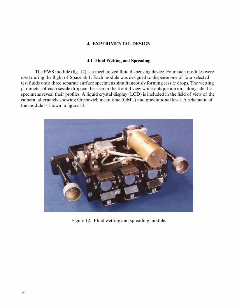
The FWS module (fig. 12) is a mechanized fluid dispensing device. Four such modules were used during the flight of Spacelab 1. Each module was designed to dispense one of four selected test fluids onto three separate surface specimens simultaneously forming sessile drops. The wetting parameter of each sessile drop can be seen in the frontal view while oblique mirrors alongside the specimens reveal their profiles. A liquid crystal display (LCD) is included in the field of view of the camera, alternately showing Greenwich mean time (GMT) and gravitational level. A schematic of the module is shown in figure 13.
Figure 12. Fluid wetting and spreading module.
17
Fluid Spreading Specimen (3 total)
LCD Time and lo-g Data Module (Part of Operations Facility)
Top of Drawer
Dispense Drivemotor
GMT and Log Data LCD’s
Elect Conn
Camera Field of View
Mirror (Typ)
5.68
Figure 13. Schematic of the FWS module.
Three identical dispensing mechanisms are behind the specimens, each comprising mainly of a storage cartridge and a screw-driven displacement piston. Each storage cartridge contained up to 1.2 cc of the test fluid. The modules were filled on the ground prior to flight. Each cartridge was capped with a blind disc while in storage. During a test run, selected test coupons replaced the blind discs. Upon actuation of the dispenser, 2 µL of the test fluid were forced through the central hole in the specimen by the screw-driven piston. The three storage volumes were isolated from one another while the drive screws were geared together to a single drive motor. A cam operated limit switch controlled the displacement of the actuation stroke.
The test fluids were selected to represent variations of viscosity and surface tension. Nominal properties of the test fluids are given in table 1.
SRG-10 is a super-refined paraffinic oil containing the additive tricresyl phosphate. It is representative of mineral oils in common industrial use. It is also used in the journal bearing experiments because its low viscosity allows long coast-down runs.
Bray 815Z is a vacuum distilled perfluoroalkylpolyether. It has the distinct property of a very low surface tension. Its large specific gravity is also unusual. It has superior performance in space applications where high vacuum and severe thermal cycling are expected.
Apiezon C is a molecular-distilled paraffinic oil commonly used in vacuum environments. Its viscosity is very similar to that of the Bray 815Z. Its surface tension and specific weight are typical of most lubricating oils in industrial use.
The polyphenyl is a 90-10 blend by weight of four- and five-ring aromatics. This special fluid was selected because it was known to exhibit oleophobic behavior. Otherwise, its properties are similar to the Apiezon C.
The surface specimens were discs made of 440C stainless steel and nominal dimensions of 1.905 cm diameter and 0.9524 cm thickness. The central hole through which the test fluid passed during dispensing was 0.91 mm in diameter. One face of each coupon was prepared for designated topographical and chemical parameters. Three coupons of different surface preparations were used in each of four FWS modules during flight. Fluid specimen combinations of these modules are in table 2.
Table 2. FWS fluid-surface finish combinations.
Oil Finish Clean Prewet Barrier CoatedSRG-10 Polished X X XBray 815Z Polished X X XApiezon C Polished X
Ground X XPolyphenyl Polished X
Ground X
The polished finish specification was random texture with 20 to 50 nm rms roughness. Ground surfaces were finished by parallel grinding to a roughness specification of 200 to 300 nm rms. Profilometry readings on a polished sample was 10 to 18 nm center line average (CLA), and those on a ground sample were 178 to 250 nm CLA across the lay and 127 to 178 nm CLA in the direction of grinding.
All specimens were first cleaned according to MSFC-SPEC-164A to establish a common baseline state of cleanliness.6 The prewetting treatment was a small drop of the test fluid placed on the experimental surface immediately after cleaning and drying. Barrier film coating was added to the surface by brushing on a fluoropolymer in solution with perfluorinated cyclic ether, following the procedure specified by MIL-B-81744A.7 The brush pattern leaves a circle of 3 to 5 mm diam-eter. The prepared samples were then clean-bagged for delivery.
19
These preparations were made at 6 weeks before scheduled launch. Due to launch delays, the actual bag age of the specimens was approximately 10 weeks when the FWS experiment was performed on Spacelab 1. This was within the limits of allowable shelf life for offgas contamination from the bagging material.
4.2 Journal Bearing
The journal bearing module, shown in figure 14, features a symmetrical, rigid rotor sup-ported by a pair of experimental journal bearings. The experimental bearings are made of glass for observation of void patterns in the bearing clearance. Inclined mirrors on either side of each bear-ing display a full view of the bearing surface. Encoding markers painted on the face of the flywheel are sensed optically. The pulse train from the 30 evenly spaced markers near the wheel rim were timed to determine the rotational speed. The single marker at a smaller radius serves to trigger cin-ematographic operation. Noncontact proximity sensors monitored the journal axis in the vicinity of each bearing. An LCD digital display alternated among GMT, rotor speed, and g-level. A sche-matic for this module is shown in figure 15. A mirror system combined the views of the bearings with that of the digital display into a compact image for filming, as shown in figure 16.
Figure 14. Journal bearing module.
20
Top of Drawer
Right Side Camera View Envelope
Handle (Typically Both Sides)Flywheel Cage
and Seal Operating Handle
Flywheel Cage and Seal
Flywheel
Disp
lay
Disp
lay
LCD
LCD
Shaft Photo Mirrors (Typically Both Ends)
Left Side Camera View Envelope
LCD Time Shared RPM, GMT and
lo-g Readout (Part of TEZG
Operations Facility)
Glass Bearing (Typically Both Ends)
Flywheel Spinup Drive Motor
RPM and Camera/Strobe Sync Light Sensors
Journal Bearing Experiment Camera Field of View
Shaft
Figure 15. Schematic of the journal bearing module.
21
IndkonProximityProbes
Closed CircuitTelevisionCamera
Mirrors
60°
CL
CL
60°
x1
y1
Figure 16. Mirror and proximity probe schematic system for the journal bearing module.
Three versions of the journal bearing module were equipped with different experimental bearings. Version 1 had plain cylindrical journal bearings. The flywheel was capable of being fit-ted with an unbalance mass of 56.7 g at a radius of 5.08 cm, yielding a centrifugal acceleration of 0.77 g at maximum rotor speed. Version 2 had equilateral, three-lobe configuration (fig. 17). The lobes were preloaded centrally such that the midarc clearance was exactly one-half of the nominal clearance. The arcs were separated from one another by an axial slot. Version 3 had plain cylin-drical journal bearings. However, the rotor was also fitted with a pair of ball bearings so that the eccentricity of the journal bearings was fixed to be nominally three-fourths of the radial clearance.
22
Preload Circle, Radians r
Largest Shaft Clearance, Radins R+cb
Oj
ObPad Radius
Figure 17. Cross-section of three-lobe journal bearing.
4.3 General Instrumentation
A thermistor in the platform area monitored the ambient temperature. A three-axis, low-g accelerometer was mounted in the experiment compartment. The noise threshold of the accelerom-eter was 0.0001 g. Temperature, four channels of rotor shaft proximity readout, and three accelera-tion signals were digitized. Together with rotor speed, camera frame speed, and GMT, a total of 14 signals were monitored during the experiment and relayed to ground. A data management microprocessor controlled experiment operations and served as the interface between TEZG and the Spacelab 1 computer.
A 16-mm camera was used to record images of both FWS and journal bearing experiments. Lens and settings are given in table 3.
Table 3. Photographic settings for TEZG.
FWS Journal BearingFocal length, mm 50 25Aperture f9 f2Distance, cm 79 46Frame rate Synchronized 24 fps for 8 s
8 fps for 8 m
23
A stroboscopic illumination system was constructed with a high intensity xenon flash with an output of 1 to 1.4 joules per flash. Flashes were triggered by the data management microproces-sor with the same pulse that caused the camera shutter to open. Aperture settings were established according to ground trials.
The entire experiment was contained in two rack-mounted drawers for flight. One drawer for storage (fig. 18) held the experiment modules, accessories, and tools when not in use and com-partments for films and FWS test coupons. The second drawer (fig. 19) was wired for power and communications and contained the low-g accelerometer, the data management microprocessor, the experiment platform, the lighting system, and the camera. Figure 20 shows more detail of the light-ing system. The entire payload of TEZG weighed 107 kg, of which 68 kg represented functional items. The remaining 39 kg were distributed among drawer bodies, structural interfaces, wiring, and various fixtures attached to the drawers.
24
Figure 18. Storage drawer.
25
Figure 19. Operations drawer.
26
Figure 20. Lighting system of experiment chamber.
27
5. EXPERIMENTAL PROCEDURE IN FLIGHT
Each run of the FWS experiment began with the selected module being mounted to the platform. The blind discs were removed and the dispensing operation switched on once to purge the passageway. A blind disc was pressed back to the seat of each cartridge to squeeze away excess fluid. Selected test coupons were positioned, and the camera was prepared. The LCD was moved to the FWS location, and the microprocessor was activated to commence the automated sequence of functional operations. The camera and lights were turned on after a delay of 3 s. The fluid dis-pensing motor was switched on after 5 s of delay from the start of the run. The dispensing opera-tion lasted approximately 0.5 s. Filming began with 24 frames per second for 8 s, then continued with 1 frame per second for 8 min.
The journal bearing module operated in a coast-down mode. The inertia of the rotor fly-wheel sustained the rotational motion against bearing friction and windage torque. A solenoid-operated actuator presses the friction wheel of the drive motor against the flywheel to spin up. Subsequent operations were controlled by a microprocessor which timed the train of 30 pulses per revolution. The friction wheel of the drive motor was disengaged from contacting the flywheel as the rotational speed reached 600 rpm. Camera operations were synchronized with the once per revolution marker of the inner encoder. Strobe lighting was flashed during shutter opening. Film-ing was terminated when the rotor speed fell below 150 rpm.
28
6. FLIGHT EXPERIMENT RESULTS
6.1 General Experiment Performance
Both FWS and journal bearing experiments were performed without any functional dif-ficulty. However, real-time display of requested telemetry data was preempted by mission man-agement for emergency communications. Omission of the real-time telemetry display did not compromise the scientific objectives of the experiment. Postflight processing of telemetry data resulted in useful records of GMT versus shutter rate for FWS, GMT versus shaft rpm for the journal bearing module, and GMT versus temperature and low-g accelerometer for both experi-ments. Telemetered data of proximity sensors of the journal bearing experiment contained no information. The fault was traced to a design error in the data management microprocessor. The low-g acceleration record revealed a burst of milli-g disturbance during the operation of the FWS experiment with SRG-10 oil. Otherwise, all experiment operations were satisfactorily executed.
6.2 Film Records
Photographic records of FWS runs yielded results in 10 out of the 12 conditions in the planned series of experiments. The two failed conditions were Bray 815Z on a clean, polished sur-face and polyphenyl blend on a clean, ground surface. In these cases, fluid never came through the central feed hole. The payload specialist recalled noticing the absence of visible oil on some speci-mens at end-of-run inspections.
The film also showed an apparent false start of module 3 (Apiezon C). A little over a sec-ond went by as if the run had started. However, fluid did not come through, and filming was inter-rupted. The subsequent frames switched to module 4 (polyphenyl blend). After module 4 scenes were over, module 3 started again. This time, a small, shining circle surrounded the feed hole, as if a fluid drop was already present. Each specimen probably had experienced partial prewetting.
Representative prints are shown in figure 21.
29
(a)
(b)
(c)
(d)
Figure 21. Representative photographs of Spacelab 1 FWS Module 1: (a) Time = 0.21 s, (b) time = 0.46 s, (c) time = 5.83 s, and (d) time = 124 s.
30
6.3 Results of Fluid Wetting and Spreading Experiment
The fluid spreading data are presented in figures 22–25. In each of these figures, the spread-ing curves of SRG-10 are shown as reference. The spreading curves of SRG-10 (fig. 22) suggest three different regimes as follows:
• Regime 1: Essentially the same growth rate was observed on all three specimens. Growth to about 3 mm equivalent wet diameter took place in about 0.3 s from the instant of appearance of oil on the specimens. This period corresponded to the displacement stroke of the dispensing piston.
• Regime 2: Oil drop size on the barrier film-coated specimen remained invariant with time. The inclined mirror showed a hemispherical profile. Oil on the other two specimens continued to spread at about an equal rate. Wet diameter grew to about 4 mm at the end of 0.6 s.
• Regime 3: The spreading rate became significantly reduced after about 0.6 s. The mean diametral growth rate reduced from about 3 mm/s at 0.6 s to 0.2 mm/s at 1 s to less than 0.01 mm/s after 4.5 min. The wet area on the prewetted specimen is visibly larger than that on the clean specimen.
Figure 22. Spacelab 1 spreading data of mineral oils—SRG-10 on various substrates.
Spre
ad D
iamet
er (m
m)
10
1
2
2
11
3
SRG-10
SRG-10
Apiezon C
Apiezon C
0 1 10 100 1,000
Time (s)
Figure 23. Spacelab 1 spreading data of mineral oils—comparison of Apiezon C with SRG-10.
31
10
10 1 10 100 1,000
Time (s)
2
–21
33SRG-10
Bray 815ZBarrier Coated, Polished
Bray 815ZPrewet, Polished
Spre
ad D
iamet
er (m
m)
F24_1521
Figure 24. Spacelab 1 spreading data of Bray 815Z compared with SRG-10.
10
10 1 10 100 1,000
Time (s)
21
133 2
SRG-10Prewet Clean
Barrier Coated
PolyphenylPreset, Polished
PolyphenylClean, Polished
Polyphenyl
Spre
ad D
iamet
er (m
m)
F25_1521
Figure 25. Spacelab 1 spreading data of polyphenyl blend compared to SRG-10.
The quality of the data does not warrant a very precise estimation of the spreading rates in various regimes. In the log-log scale presentation for time beginning at 0.1 s through the full dura-tion of each experiment run, the spreading data fit a two slope description reasonably well. The two slopes correspond to power law relationships with exponents of about 0.5 and 0.07, respectively, for either the clean specimen or the prewetted specimen.
The shape of the wet spot became oblong on the prewetted surface, with the major axis about 45 degrees counterclockwise from the reference axis. Occurrence of milli-g level disturbance during this period is indicated in the accelerometer record. The fact that such a shape distortion could not be observed on the clean surface suggests that some threshold of surface equilibrium could have been affected by the prewetting treatment.
In the case of the barrier film-coated surface, very little change in the image of the oil drop took place after completion of the dispensing action.
32
The significance of the Apiezon-C runs is clouded by the somewhat irregular operation noted previously. Nevertheless, the apparent spreading rate appears to be slower than the cor-responding value of SRG-10 as suggested by figure 23. This can be associated with the difference in viscosity of the two fluids. The lack of distinguishing features of the run of Apiezon-C on the grinding-finished specimen is a little misleading. Meniscus capillary action associated with the ground surface texture is not isotropic, so that the resulting wet interface would not be circular. Since the circle is the shape of the largest enclosed area for a given perimeter, the perimeter of a noncircular shape would be larger than that indicated by the diameter of the equivalent wet circle. Also, the wet perimeter on the grinding-finished specimen was consistently less discernible than those on the other two specimens.
In figure 24, the spreading behavior of Bray-815Z is compared with that of SRG-10. Here again, the spreading rate based on the equivalent diameter does not tell the whole story. The drop shape on the prewetted-polished surface became oblong almost as soon as the dispensing operation was over. The major axis was vertical. The lower perimeter moved faster and soon became difficult to recognize, while at the same time, the upper perimeter remained very distinct. The cause of this peculiar behavior is not known. On the barrier film-coated specimen, the overall appearance is very similar to that of SRG-10. The slightly larger final diameter is consistent with the lower surface tension.
The spreading data of the polyphenyl blend are shown in figure 25. A limiting drop size appeared to have been reached in about 1 s on each specimen. There are no significant differences in the spreading behavior on the two types of surface specimens.
Figure 26 shows the results of a postflight verification of FWS of SRG-10 in the Earth grav-ity environment. The specimen surfaces were oriented in a horizontal plane facing upwards. Thus, gravity added to the surface tension caused pressure to promote spreading during the early phase when the drop profile was relatively tall. The second phase, in which gravity no longer predomi-nated the spreading process, began about 0.2 s sooner. Gravity also caused the final drop size on the barrier film-coated sample to be somewhat larger.
33
Spre
ad D
iamet
er (m
m)
10
1
SL-1
Ground
0 1 10 100 1,000
Time (s)(a)
(b)
(c)
Spre
ad D
iamet
er (m
m)
10
1
SL-1
Ground
0 1 10 100 1,000
Time (s)
Spre
ad D
iamet
er (m
m)
10
1
SL-1
Ground
0 1 10 100 1,000
Time (s)
Figure 26. Comparison of FWS experiments in SL-1 and in ground environment: (a) Clean-polished surfaces, (b) prewetted-polished surfaces, and (c) barrier film-coated, polished surfaces.
6.4 Results of Journal Bearing Experiment
Primary data from each journal bearing run consisted of cinematographic films, rotor speed, and four channels of rotor-axis position signals. Each data record was associated with GMT and can be correlated with one another to yield functional behavior of the bearings as some may be affected by interfacial phenomena. Observation of the two-phase morphology in the capillary space of bearing clearance is the major motivation for performing the journal bearing experiment during the flight of Spacelab 1. Monitoring of the shaft motion was intended to add knowledge to the relationship between the two-phase morphology and rotor dynamics. Unfortunately, the proximity data were lost; any conclusions are drawn from the image records.
34
A discussion of the photographic setup will aid understanding the information contained in the image records. As seen in figure 17, the transparent experimental bearing is fanned by mirrors inclined to the line of sight of the camera by 60 degrees on either side. At any instant, the camera view includes the full circumference of the bearing surface through the transparent bushing. Any part of the bearing clearance which is not filled by the lubricating oil would appear as a bright patch. Variations in geometrical and topographical features of the rotor surface would affect the morphology of the void regions. By triggering the camera shutter with a once per revolution encoding marker on the rotor, events in sync with the rotor motion would have identical images in successive video frames. Lack of uniformity would be seen as variations amongst the three views of each bearing. In the absence of geometrical asymmetry, variations amongst these views in the same frame of film would indicate some transverse motion of the rotor axis. A state of nonsynchronous motion of the rotor would be reflected by a frame-to-frame fluctuation in the cinematographic record.
Representative frames of the cinematographic film of journal bearing module 1 with the balanced rotor are reproduced in figure 27. No voids were seen in the bearing on the left-hand side. On the right, void streaks extended around the bearing completely. Such a two-phase structure was proposed as a theoretical possibility and was associated with a dynamically unstable system, but no previous experimental observation has been reported.5 Figure 27(a) shows this condition near the top speed of the coast-down run. The presence of rotor eccentricity, even though there was no transverse acting force, is indicated by the lack of symmetry as revealed by the right mirror view. Frame-to-frame review indicated that shifts in the rotor position repeated in pairs, therefore a whirl with a rate equal to one-half of the rotational rate was in evidence. The pattern of alternate-frame fluctuations persisted throughout the entire run. As speed decreased, however, the total extent of voids also appeared to reduce.
With the introduction of mass-unbalance, in version 1B, there was a definite concentration of voids immediately behind the plane of the unbalance mass. As revealed by figure 28(a) and (b), no significant difference between successive frames could be recognized. The sequence of image records suggested a flow field in an eccentric bearing clearance with the journal center whirling in synchronism with the rotational rate. The total extent of the void region reduced with speed. Upon comparing figure 28(a) and (c) with figure 27(a) and (c), one may observe that the overall two-phase flow structure, while affected by the rotational rate, does not appear to depend on the presence of synchronous whirl, which was caused by rotor balance. Near the end of the coast-down run, there was a sudden increase in the total extent of voids as shown in figure 28(d).
35
(a)
(b)
(c)
F27_1521
Figure 27. Module 1, balanced rotor: (a) 618 rpm. Extensive void streamers, lack of symmetry revealed in right mirror view; (b) 279 rpm. Void region is seen mainly at top of central view; and (c) subsequent frame to (b), 279 rpm. Additional band of streamers accentuate every-other-frame fluctuations.
36
(a)
(b)
(c)
(d)
Figure 28. Module 1, unbalanced rotor: (a) 608 rpm. Right mirror view is significantly different from the other two views; (b) 608 rpm. Subsequent frame to (a) but no significant difference. Every-other-frame fluctuations not noticeable; (c) 279 rpm. Substantially less voids than (a) and (b), very similar to figure 27(c); and (d) 162 rpm. Void region is larger than that seen at 279 rpm, similar to figure 27(a).
37
In the image records of journal bearing module 2, voids were primarily located down-stream of the minimum gap points of each arc. The appearance did not change much with speed. For journal bearing module 3, shadow and glare in the image records preclude definitive recogni-tion of voids. However, occasional appearance of a circulating bubble alludes to their presence, as expected.
Rotational speed versus time data were downlinked from Spacelab 1 for journal bearing module 1 in both the balanced (1A) and the unbalanced (1B) configurations. Postflight ground check runs with a horizontal orientation of the journal axis were performed for comparison. This is summarized in table 4 and shown graphically in figure 29. The ground runs do not show much dependence on whether the rotor is balanced or not, indicating the dominance of gravity load in fixing the operating eccentricity of the journal axis. A slightly longer coast-down time with rotor unbalance suggests a larger void content in the bearing clearance due to vibrational response. Significantly longer coast-down times of Spacelab 1 runs are indicative of more concentric running conditions in the absence of gravity load. The longer coast-down time of the unbalanced rotor in a zero gravity condition is interesting. Reduced viscous friction of the bearing may be due to the combination of a smaller whirl orbit and an increased void content in the bearing clearance. Unfortunately, proximity data were lost so that one cannot discriminate the relative magnitudes of these two contributive factors. Comparisons of coast-down behaviors of the other journal bearing modules between Spacelab 1 and ground runs show lesser influence of gravity, as expected.
Table 4. Coast-down data comparison of Spacelab 1 flight data to ground data.
Figure 29. Coast-down behaviors of journal bearing module 1A (balanced rotor) and 1B (unbalanced rotor). Comparison of Spacelab 1 and ground check runs.
39
7. SUMMARY
7.1 Fluid Wetting and Spreading
The FWS experiment was performed with 12 fluid-surface combinations. The data on a light mineral oil yielded quantitative spreading rates. In each case, a rapid early phase was fol-lowed by a much slower late phase. Presumably, these two phases represent the relative dominance of hydrodynamic and thermodynamic driving forces, respectively. A somewhat higher spreading rate in both phases was discernible for the surface prewetted by the oil. A barrier film coating effec-tively suppressed the spreading process in all cases. Comparable measurements on the ground, with the surface specimen holding the fluid drop on top, showed a slight increase in the spreading rate of the early phase. Within experimental error, the spreading rate of the late phase was not affected by Earth gravity. For the fluids tested on Spacelab 1, spreading of the secondary film occurred in about 0.3 s for a drop volume of 2 µL. Following are details of the spreading process:
• The spreading rate of the early phase was markedly reduced by a high fluid viscosity.
• Spreading of the primary film on a clean polished surface of 440C stainless steel was very slow.
• The surface texture of grinding caused anisotropy in the spreading process of the secondary film.
• Marangoni behavior of the polyphenyl blend curtailed its spreading in the Spacelab 1 experiment.
7.2 Journal Bearing
Two-phase flow morphology in plain journal bearing (module 1A) was a randomly dis-persed system of streamers in zero gravity. In the equivalent ground condition with a vertical journal axis, the streamers were regularly stratified. The plain journal bearing with a balanced rotor was always unstable regardless of the appearance of the streamers in the zero gravity environment.
For an unbalanced rotor in plain journal bearings, there was a critical speed. At higher speeds, a state of stable synchronous whirl was maintained. At lower speeds, the rotor sustains a half-frequency whirl similar to a balanced rotor. A distinct change of two-phase morphology accompanied the change of rotor motion across the critical speed in the Spacelab 1 experiment as the rotor coasted down.
In fixed-geometry bearing clearances, the void regions aggregated immediately downstream of the minimum gap location.
40
41
REFERENCES
1. Young, T.: “An Essay on the Cohesion of Fluids,” Phil. Trans. R. Soc. Lond., Vol. 95, pp. 65–87, doi: 10.1098/rstl.1805.0005, 1805.
2. Sumner, C.G.: Symposium on Detergency, Chemical Publishing Co., New York, p. 15, 1937.
3. Zisman, W.A.: in Relation of the Equilibrium Contact Angle to Liquid and Solid Constitution, “Contact Angle, Wettability, and Adhesion,” Advances in Chemistry, Vol. 43, pp. 1–51, Chapter doi: 10.1021/ba-1964-0043.ch001, 1964.
4. Floberg, L.: “Cavitation Boundary Conditions with Regard to the Number of Streamers and Tensile Strength of the Liquid,” Cavitation and Related Phenomena in Lubrication, Proc. 1st Leeds-Lyon Symposium on Tribology, pp. 31–35, 1974.
5. Pan, C.H.T.: “An Improved Short Bearing Analysis for the Submerged Operation of Plain Journal Bearings and Squeeze-Film Dampers, ASTM J. Trib., Vol. 102, No. 3, pp. 320–331, doi: 10.1115/1.3251526, July 1, 1980.
6. MSFC-SPEC-164A, Cleanliness of Components for Use in Oxygen, Fuel, and Pneumatic Systems, Specification for, NASA Marshall Space Flight Center, Huntsville, AL, October 1,
1970.
7. MIL-B-81744A, Barrier Coating Solution, Lubricant Migration Deterring, Military Specification, August 31, 1973.
42
REPORT DOCUMENTATION PAGE Form ApprovedOMB No. 0704-0188
The public reporting burden for this collection of information is estimated to average 1 hour per response, including the time for reviewing instructions, searching existing data sources, gathering and maintaining the data needed, and completing and reviewing the collection of information. Send comments regarding this burden estimate or any other aspect of this collection of information, including suggestions for reducing this burden, to Department of Defense, Washington Headquarters Services, Directorate for Information Operation and Reports (0704-0188), 1215 Jefferson Davis Highway, Suite 1204, Arlington, VA 22202-4302. Respondents should be aware that notwithstanding any other provision of law, no person shall be subject to any penalty for failing to comply with a collection of information if it does not display a currently valid OMB control number.PLEASE DO NOT RETURN YOUR FORM TO THE ABOVE ADDRESS.
1. REPORT DATE (DD-MM-YYYY) 2. REPORT TYPE 3. DATES COVERED (From - To)
4. TITLE AND SUBTITLE 5a. CONTRACT NUMBER
5b. GRANT NUMBER
5c. PROGRAM ELEMENT NUMBER
6. AUTHOR(S) 5d. PROJECT NUMBER
5e. TASK NUMBER
5f. WORK UNIT NUMBER
7. PERFORMING ORGANIZATION NAME(S) AND ADDRESS(ES) 8. PERFORMING ORGANIZATION REPORT NUMBER
9. SPONSORING/MONITORING AGENCY NAME(S) AND ADDRESS(ES) 10. SPONSORING/MONITOR’S ACRONYM(S)
11. SPONSORING/MONITORING REPORT NUMBER
12. DISTRIBUTION/AVAILABILITY STATEMENT
13. SUPPLEMENTARY NOTES
14. ABSTRACT
15. SUBJECT TERMS
16. SECURITY CLASSIFICATION OF:a. REPORT b. ABSTRACT c. THIS PAGE
17. LIMITATION OF ABSTRACT 18. NUMBER OF PAGES
19a. NAME OF RESPONSIBLE PERSON
19b. TELEPHONE NUMBER (Include area code)
Standard Form 298 (Rev. 8-98)Prescribed by ANSI Std. Z39-18
Tribology Experiment in Zero Gravity
C.H.T. Pan,* R.L. Gause, A.F. Whitaker, and M.M. Finckenor
George C. Marshall Space Flight CenterHuntsville, AL 35812
National Aeronautics and Space AdministrationWashington, DC 20546–0001
Unclassified-UnlimitedSubject Category 27Availability: NASA STI Information Desk (757–864–9658)
Prepared for the Materials and Processes Laboratory, Engineering Directorate*Global Technology, Millbury, MA
A tribology experiment in zero gravity was performed during the orbital flight of Spacelab 1 to study the motion of liquid lubri-cants over solid surfaces. The absence of a significant gravitational force facilitates observation of such motions as controlled by interfacial and capillary forces. Two experimental configurations were used. One deals with the liquid on one solid surface, and the other with the liquid between a pair of closed spaced surfaces. Time sequence photographs of fluid motion on a solid surface yielded spreading rate data of several fluid-surface combinations. In general, a slow spreading process as governed by the tertiary junction can be distinguished from a more rapid process which is driven by surface tension controlled internal fluid pressure. Pho-tographs were also taken through the transparent bushings of several experimental journal bearings. Morphology of incomplete fluid films and its fluctuation with time suggest the presence or absence of unsteady phenomena of the bearing-rotor system in various arrangements.
Since its founding, NASA has been dedicated to the advancement of aeronautics and space science. The NASA Scientific and Technical Information (STI) Program Office plays a key part in helping NASA maintain this important role.
The NASA STI Program Office is operated by Langley Research Center, the lead center for NASA’s scientific and technical information. The NASA STI Program Office provides access to the NASA STI Database, the largest collection of aeronautical and space science STI in the world. The Program Office is also NASA’s institutional mechanism for disseminating the results of its research and development activities. These results are published by NASA in the NASA STI Report Series, which includes the following report types:
• TECHNICAL PUBLICATION. Reports of completed research or a major significant phase of research that present the results of NASA programs and include extensive data or theoretical analysis. Includes compilations of significant scientific and technical data and information deemed to be of continuing reference value. NASA’s counterpart of peer-reviewed formal professional papers but has less stringent limitations on manuscript length and extent of graphic presentations.
• TECHNICAL MEMORANDUM. Scientific and technical findings that are preliminary or of specialized interest, e.g., quick release reports, working papers, and bibliographies that contain minimal annotation. Does not contain extensive analysis.
• CONTRACTOR REPORT. Scientific and technical findings by NASA-sponsored contractors and grantees.
• CONFERENCE PUBLICATION. Collected papers from scientific and technical conferences, symposia, seminars, or other meetings sponsored or cosponsored by NASA.
• SPECIAL PUBLICATION. Scientific, technical, or historical information from NASA programs, projects, and mission, often concerned with subjects having substantial public interest.
• TECHNICAL TRANSLATION. English-language translations of foreign
scientific and technical material pertinent to NASA’s mission.
Specialized services that complement the STI Program Office’s diverse offerings include creating custom thesauri, building customized databases, organizing and publishing research results…even providing videos.
For more information about the NASA STI Program Office, see the following:
• Access the NASA STI program home page at <http://www.sti.nasa.gov>