23
PRODUCT CATALOG TOT AL LUB RICA TION MANAGEMENT SOLUTIONS www.tricocorp.com | 800.558.7008

7/18/2019 Trico Lubricacion Centralizada
http://slidepdf.com/reader/full/trico-lubricacion-centralizada 1/22
PRODUCT
CATALOGTOTAL LUBRICATIONMANAGEMENT SOLUTION
www.tricocorp.com | 800.558.7008

7/18/2019 Trico Lubricacion Centralizada
http://slidepdf.com/reader/full/trico-lubricacion-centralizada 2/22www.tricoco
800.558.7
INTRODUCTION TO CENTRAL LUBRICATION
SINGLE LINE RESISTANCE SYSTEMS
Trico central lubrication products are commonly known asSingle Line Resistance Systems. They are used throughoutindustry where reliable oil lubrication is required. The basicprinciples of these systems are:
• Oil lubrication
• Pump operation to deliver the oil to the system
• Individual control of oil lubrication amounts at eachlubrication point
• Meter and control units create resistance to flow toapportion oil delivery
• Total loss or re-circulating systems
Common applications are shown below. These are found on punchpresses, milling machines, printing presses, injection moldingmachines, textile machinery, and all types of machine tools.
POSITIVE DISPLACEMENT
INJECTION SYSTEMS
Trico offers a line of products that complement the single lineresistance systems. Instead of using meter or control units,a piston dispenses a pre-set amount of oil at each cycle ofthe pump. These systems do require that different pumps beused than with single line resistance systems. All fittings andtubings are interchangeable between the two systems.
Ball Bearings Plain Bearings
Flat Slides Cylindrical Slides
Ball Bearing Slides Cams
Gears Chains

7/18/2019 Trico Lubricacion Centralizada
http://slidepdf.com/reader/full/trico-lubricacion-centralizada 3/22
L2
ww.tricocorp.com
800.558.7008
BASIC TYPES OF SYSTEMS
MANUAL PUMPS
These single-shot systems use amanually actuated pump for applicationswhere infrequent lubrication is required.
Manual or single-shot pumps use meterunits to apportion the amount of oil ateach lubrication point.
FEATURES
• Low cost, simplified installationand operation
• Manual and spring discharge pumps
• Reservoir capacities to 450 cc
• Applications with less than 50 points
• Used with meter units
• Total loss systems
AUTOMATIC CYCLIC PUMPS
For those who need automatic lubrication on an intermittent basis, a cyclic systemis required. Cost for these systems areeconomical and vary based on the typeof control used to regulate the lubeinterval and capacity of the reservoir.
Automatic Cyclic pumps use meter unitsto apportion the amount of oil at eachlubrication point.
FEATURES
• Spring discharge and gear pumps
• Adjustable interval timesbetween lubrication
• Adjustable oil volume outputs
• Reservoir capacities up to 20 liters
• Applications with up to 50lubrication points
• Used with meter units
• Total loss systems
CONTINUOUS PUMPS
For large lubrication requirements acontinuous system should be used. Thesesystems are commonly used on equipmewith a high number of lubrication points.
FEATURES
• Gear pump design
• Constant oil volume outputs
• Reservoir capacities up to 20 liters
• Applications with up to 200lubrication points
• Used with control units
• Total loss systems orre-circulating systems
Continuous pumps use control unitsto apportion the amount of oil at eachlubrication point.

7/18/2019 Trico Lubricacion Centralizada
http://slidepdf.com/reader/full/trico-lubricacion-centralizada 4/22www.tricoco
800.558.7
POSITIVE DISPLACEMENT INJECTORS
Positive Displacement Injectors (PDI!s) are an excellent means of providingoil lubrication to machinery. Using a piston principle, the PDI will lubricate
individual points with specific amounts of oil. There are 6 output sizes tochoose from: 0.06, 0.10, 0.16, 0.20, 0.30, and 0.50 cc!s per cycle. A typicalsystem will include a pump, any number of PDI!s, and the necessary tubingand fittings.
At the start of the lubrication cycle, the PE-34 or PE-44 Series pump buildspressure. Upon pressure build-up, the PDI!s deliver the pre-set amount ofoil. At the end of the lubrication cycle, a pressure unloading valve opens toreturn line pressure to 0 PSI. This allows the PDI!s to reset for the next cycle.
HOW TO ORDER
1. For each lubrication point, select the appropriate Positive
Displacement Injector (PDI) based on the oil output per cycle.
2. Select the manifolds required for mounting thatsimplify installation.
3. Select either a PE-34 Series Automatic Cyclic pump withbuilt-in cycle controls, or a PE-44 Series standard pump thatuses external controls for the lubrication cycle. A choice ofreservoir capacities is available for both pumps.
88
15 1/8 BSPT
Inlet "
2 places
(Note: All dimensions are mm.)
PDI SPECIFICATIONS
Inlet Thread Size 1/8 BSPT
Outlet Thread Size M8 x 1.0
Operating Pressure 200 PSI
Pump Required PE-34 or PE-44
Oil Viscosity 30-250 CST (150-1250 SUS)
Model No.Output Volume
(cc/cycle)
PDI-06 0.06
PDI-10 0.10
PDI-16 0.16
PDI-20 0.20
PDI-30 0.30
PDI-50 0.50
PDI SELECTION CHART
Model No. No. of OutletsDimensions (mm)
A B
PDM-42 2 47 37
PDM-43 3 62 52
PDM-44 4 77 67
PDM-45 5 92 82
PDM-46 6 107 97
MANIFOLDS SELECTION CHART
MANIFOLD SPECIFICATIONS
5.8 (2)
Manifold
A
15
B
PDI
1/8 BSPTOutlet Thread
M8 x 1.0 Thread
Connection Port Thread Size No. of Ports
Inlet 1/8 BSPT 2
Outlet 1/8 BSPT 2 to 6

7/18/2019 Trico Lubricacion Centralizada
http://slidepdf.com/reader/full/trico-lubricacion-centralizada 5/22
L4
ww.tricocorp.com
800.558.7008
PUMPS FOR PDI SYSTEMS
PUMP SELECTION CHART
290 (6L)
310 (8L)
470 (20L)
355 (6L & 8L)480 (20L)
338 (6L & 8L)457 (20L)
95 (6L & 8L)190 (20L)
188 (6L)201 (8L)
234 (20L)
(Note: All dimensions are mm.)
6, 8 and 20 Liter Reservoirs
170227190
275
3 Liter Reservoir
PUMP SPECIFICATIONS
PE-34 and PE-44 Series
Motor Voltage 110-1"50/60 Standard
220-1"50/60 Optional
Pump Type Gear Pump
Maximum Pressure 200 PSI
Maximum Flow 100 cc/min
Output Connection 5/16-24 (f)
Seals Buna-N
Oil Viscosity 30"250 CST (150-1250 SUS)
ModelNo.
Pump TypeReservoir
Capacity (liters)Oil Delivery
TimeInterval Time
Between Cycles
PE-3403Auto-Cyclic
with IntegralDigital
Controls
3
1"999 sec 1"999 minutesPE-3406 6
PE-3408 8
PE-3420 20
PE-4403 StandardPump
for UserInstalledControls
3
User
InstalledUser Installed
PE-4406 6
PE-4408 8
PE-4420 20
7/18/2019 Trico Lubricacion Centralizada
http://slidepdf.com/reader/full/trico-lubricacion-centralizada 6/22www.tricoco
800.558.7
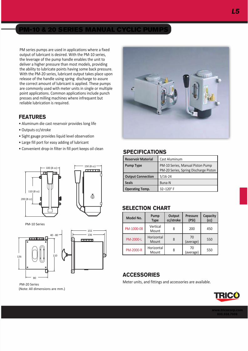
PM-10 & 20 SERIES MANUAL CYCLIC PUMPS
PM series pumps are used in applications where a fixedoutput of lubricant is desired. With the PM-10 series,
the leverage of the pump handle enables the unit todeliver a higher pressure than most models, providingthe ability to lubricate points having some back pressure.With the PM-20 series, lubricant output takes place uponrelease of the handle using spring discharge to assurethe correct amount of lubricant is applied. These pumpsare commonly used with meter units in single or multiplepoint applications. Common applications include punchpresses and milling machines where infrequent butreliable lubrication is required.
FEATURES
• Aluminum die cast reservoir provides long life
• Outputs cc/stroke
• Sight gauge provides liquid level observation
• Large fill port for easy adding of lubricant
• Convenient drop-in filter in fill port keeps oil clean
ACCESSORIES
Meter units, and fittings and accessories are available.
PM-10 Series
200 (8 cc)
110 (8 cc)
100 (8 cc)150 (8 cc)
Reservoir Material Cast Aluminum
Pump Type PM-10 Series, Manual Piston Pump
PM-20 Series, Spring Discharge Piston
Output Connection 5/16-24
Seals Buna-NOperating Temp. 32"120° F
SPECIFICATIONS
155
136
SELECTION CHART
126 110
80
(Note: All dimensions are mm.)
40 - 80
PM-20 Series
126
Model No.PumpType
Outputcc/stroke
Pressure(PSI)
Capacity(cc)
PM-1000-08VerticalMount
8 200 450
PM-2000-LHorizontal
Mount8
70(average)
550
PM-2000-RHorizontal
Mount8
70(average)
550
7/18/2019 Trico Lubricacion Centralizada
http://slidepdf.com/reader/full/trico-lubricacion-centralizada 7/22
L6
ww.tricocorp.com
800.558.7008
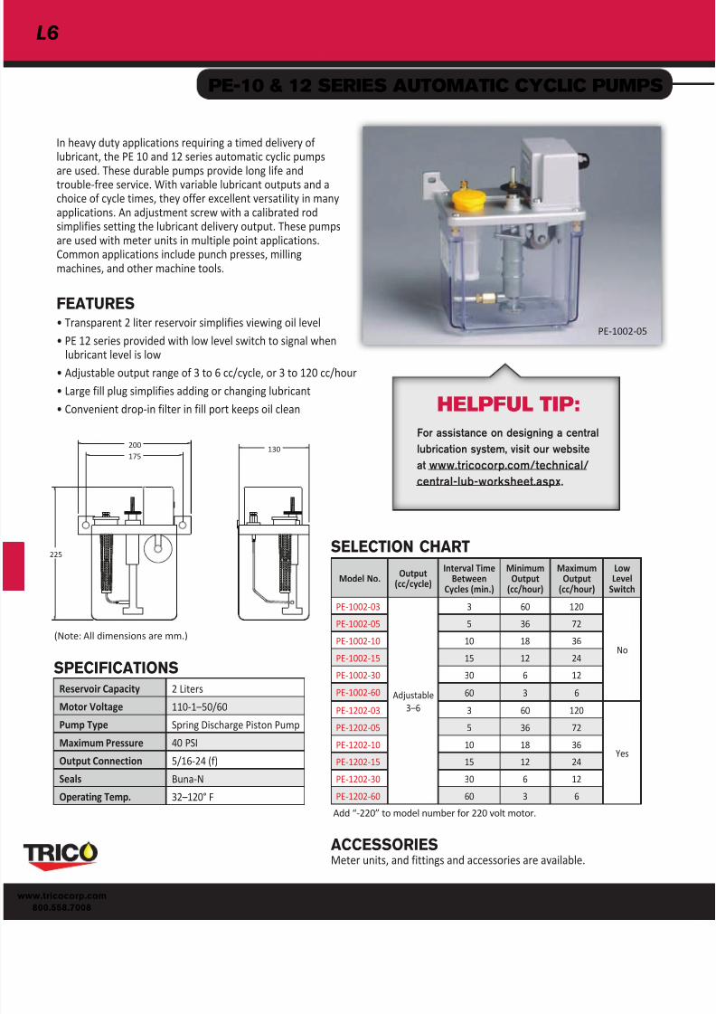
PE-10 & 12 SERIES AUTOMATIC CYCLIC PUMPS
In heavy duty applications requiring a timed delivery oflubricant, the PE 10 and 12 series automatic cyclic pumpsare used. These durable pumps provide long life andtrouble-free service. With variable lubricant outputs and achoice of cycle times, they offer excellent versatility in manyapplications. An adjustment screw with a calibrated rodsimplifies setting the lubricant delivery output. These pumpsare used with meter units in multiple point applications.Common applications include punch presses, millingmachines, and other machine tools.
FEATURES
• Transparent 2 liter reservoir simplifies viewing oil level
• PE 12 series provided with low level switch to signal when
lubricant level is low• Adjustable output range of 3 to 6 cc/cycle, or 3 to 120 cc/hour
• Large fill plug simplifies adding or changing lubricant
• Convenient drop-in filter in fill port keeps oil clean
PE-1002-05
Reservoir Capacity 2 Liters
Motor Voltage 110-1"50/60Pump Type Spring Discharge Piston Pump
Maximum Pressure 40 PSI
Output Connection 5/16-24 (f)
Seals Buna-N
Operating Temp. 32"120° F
SPECIFICATIONS
Model No.Output
(cc/cycle)
Interval TimeBetween
Cycles (min.)
MinimumOutput
(cc/hour)
MaximumOutput
(cc/hour)
LowLevel
Switch
PE-1002-03
Adjustable
3"6
3 60 120
No
PE-1002-05 5 36 72
PE-1002-10 10 18 36
PE-1002-15 15 12 24
PE-1002-30 30 6 12
PE-1002-60 60 3 6
PE-1202-03 3 60 120
Yes
PE-1202-05 5 36 72
PE-1202-10 10 18 36
PE-1202-15 15 12 24
PE-1202-30 30 6 12
PE-1202-60 60 3 6
SELECTION CHART
Add #-220$ to model number for 220 volt motor.
(Note: All dimensions are mm.)
200
175
225
130
ACCESSORIESMeter units, and fittings and accessories are available.
HELPFUL TIP:
For assistance on designing a central
lubrication system, visit our website
at www.tricocorp.com/technical/
central-lub-worksheet.aspx.

7/18/2019 Trico Lubricacion Centralizada
http://slidepdf.com/reader/full/trico-lubricacion-centralizada 8/22www.tricoco
800.558.7
PE-20, 22, & 24 SERIES AUTOMATIC CYCLIC PUMPS
The PE-20 series pumps are designed for automatic cyclic systems
with fewer than 50 points. These pumps are ideal for punch pressesand machine tools where small and consistent amounts of lubricantare required. These pumps are used with meter units in multiplepoint applications.
ACCESSORIES Meter units, and fittings and accessories are available.
FEATURES
PE-20 Series
• Adjustable interval time between lubrication cycles ofup to 60 minutes
• Heavy duty plastic reservoir simplifies oil level viewing
• Choice of 6 cc or 15 cc output per cycle
• Low level switch with alarm
PE-22 Series
• Adjustable interval time between lubrication cycles ofup to 60 minutes
• Heavy duty plastic reservoir simplifies oil level viewing
• Choice of 6 cc or 15 cc output per cycle
• Low level switch with alarm
• Pressure gauge
PE-24 Series
• Adjustable interval time between lubrication cycles ofup to 180 minutes
• Heavy duty plastic reservoir simplifies oil level viewing
• Adjustable output cycle time of 1-180 sec., flow rate of200 cc/min
• Low level switch with alarm• Pressure gauge
255
165205
172-180
110
(Note: All dimensions are mm.)
PE-2002-15 PE-2202-06 PE-2402
SPECIFICATIONS
SELECTION CHART
Add #-220$ to model number for 220 volt motor.
Reservoir Capacity 2 Liters
Motor Voltage110-1"50/60 Standard220-1-50/60 Optional
Pump Type Gear Pump
Maximum PressurePE-20, 22 Series: 100 PSIPE-24 Series: 70 PSI
Output Connection 5/16-24 (f)
Seals Buna-N
Operating Temp. 32"120° F
Model No. OutputInterval Time
BetweenCycles
MinimumOutput
(cc/hour)
LowLevel
Switch
Low LevelAlarm andPressure
Gauge
PE-2002-06 6 cc/cycle
0 min.to 60 min.
6
Yes
NoPE-2002-15 15 cc/cycle 15
PE-2202-06 6 cc/cycle 6
Yes
PE-2202-15 15 cc/cycle 15
PE-2402
3.33 cc/sec.Variable
delivery timeof 1-180 sec.
1 min.to 180 min.
1.1

7/18/2019 Trico Lubricacion Centralizada
http://slidepdf.com/reader/full/trico-lubricacion-centralizada 9/22
L8
ww.tricocorp.com
800.558.7008
PE-30 & PE-32 SERIES AUTOMATIC CYCLIC PUMPS
The PE-30 & PE-32 series are the most versatile automatic cyclicpumps available. Both the lubricant dispensing time, and thetime interval between cycles is digitally controlled. With reservoirsizes up to 20 liters, these pumps can handle systems with up to100 lubrication points. Applications include large printing pressesand injection molding machines. These pumps are used withmeter units in multiple point applications.
FEATURES
PE-30 & PE-32 Series
• Low level switch with alarm
• Pressure gauge• Heavy duty plastic reservoir (3 liter) simplifies oil levelviewing. Metal reservoirs available in 6, 8, and 20 litersfor larger systems.
PE-30 Series
• Adjustable output cycle time of 1-180 seconds, flow rateof 200 cc/min
• Adjustable interval time between lubrication cycles of3"999 minutes
PE-32 Series
• Adjustable output cycle time of 1-999 seconds, flow rateof 250 cc/min
• Adjustable interval time between lubrication cycles of3"999 minutes
• Pressure adjustment valve
• Pressure switch, with reset button, shuts down pump ifsystem pressure drops below set level, protecting againstline or component failure
ACCESSORIESMeter units, and fittings and accessories are available
PE-3003
290 (6L)
310 (8L)470 (20L)
355 (6L & 8L)457 (20L)
338 (6L & 8L)460 (20L)
95 (6L & 8L)190 (20L)
188 (6L)201 (8L)
234 (20L)
6, 8 and 20 Liter Reservoirs
170225195
255
(Note: All dimensions are mm.)
3 Liter Reservoir
SPECIFICATIONS
PE-3203
SELECTION CHART
Add #-220$ to model number for 220 volt motor.
Reservoir Capacity 3 Liter Plastic6, 8, and 20 Liter Steel
Motor Voltage 110-1"50/60 Standard220-1-50/60 Optional
Pump Type Gear Pump
Maximum Pressure 100 PSI - PE 30140 PSI - PE 32
Output Connection 5/16-24 (f)
Seals Buna-N
Operating Temp. 32"120° F
Model No.ReservoirCapacity(liters)
ReservoirMaterial Output
Intrval Time*Between
Cycles
MinimumOutput
(cc/hour)
PE-3003 3 Plastic3.33 cc/sec.
Variabledeliverytime of
1"180 sec.3"999
minutes .2
PE-3006 6
MetalPE-3008 8
PE-3020 20
PE-3203 3 Plastic4.17 cc/sec.
Variabledeliverytime of
1"999 sec.
PE-3206 6
MetalPE-3208 8
PE-3220 20

7/18/2019 Trico Lubricacion Centralizada
http://slidepdf.com/reader/full/trico-lubricacion-centralizada 10/22www.tricoco
800.558.7
PE-40 & PE-50 SERIES CONTINUOUS SYSTEM PUMPS
215 (8L)270 (20L)
328 (6L)357 (8L)
515 (20L)
339
259 (6L)291 (8L)
388 (20L)
(Note: All dimensions are mm.)
PE-40 and PE-506, 8 and 20 Liter Reservoirs
225
205
265
140
160PE-40 and PE-503 Liter Reservoirs
FEATURES
PE-40 and PE-50 Series
• Standard float switch provides signal when lubricant levelis low
• Easy view plastic reservoir on 3 liter models, steelreservoir with sight gauge on 6, 8 and 20 liter reservoirs
• Return to tank port available on 6, 8 and 20 liter modelsfor returning unused oil to reservoir
• Provided with pressure gauge as standard
• Safety relief valve assures reliable performance
PE-40 Series
• Pressure switch, with reset button, shuts down pump if
system pressure drops below set level, protecting againstline or component failure
PE-5003PE-4003
Trico!s continuous system pumps are designed for applications
where lubrication of critical components is needed on acontinual basis, rather than on a timed basis. Using continuoussystem control units, these pumps provide lubricant at flow ratesof 250 cc/min. Common applications include injection molding,printing presses, punch presses, and milling machines.
SPECIFICATIONS
Add #-220$ to model number for 220 volt motor.
*Refer to Accessories document for accessories on return to tank port pumps.
SELECTION CHART
Reservoir Capacity 3 Liter Plastic6, 8, and 20 Liter Steel
Motor Voltage 110-1"50/60 Standard220-1-50/60 Optional
Pump Type Gear Pump
Maximum Pressure 140 PSI
Output Connection 5/16-24 (f)
Seals Buna-N
Operating Temp. 32"120° F
Model No.(standard)
Model No.(with returnto tank port)
PressureSwitch
ReservoirCapacity(liters)
ReservoirMaterial
OutputVolume(cc/min)
PE-4003 %
Yes
3 Platic
250
PE-4006 PE-4206 6MetalPE-4008 PE-4208 8
PE-4020 PE-4220 20
PE-5003 %
No
3 Plastic
PE-5006 PE-5206 6
MetalPE-5008 PE-5208 8
PE-5020 PE-5220 20

7/18/2019 Trico Lubricacion Centralizada
http://slidepdf.com/reader/full/trico-lubricacion-centralizada 11/22
L10
ww.tricocorp.com
800.558.7008
METER & CONTROL UNITS
Meter units are used
with all cyclic systemelectric and manualpumps to provideprecise control ofthe lubricant to eachlubrication point. Aspring loaded checkvalve keeps air fromentering the systemwhen lubricant is notbeing supplied to themeter unit.
Control units are usedwith all continuoussystem electric pumpsto provide precisecontrol of the lubricantto each lubricationpoint. Because pumpflow is continuous, aninternal check valve isnot required.
METER AND CONTROL UNITS
Trico offers 8 different flow rates for meter units (3/0"5)and 10 for control units (5/0"5). These units are preciselymanufactured to accurately apportion oil at each point. To
the left is a chart that displays recommended flow rates fordifferent types of systems.
The relative flow delivery indicates the difference in the flowrates of the meter and control rates. The smallest flow rate is#5/0$ and the highest flow rate is #5$. Each meter and controlunit will allow approximately twice as much flow as the nextsmaller size, within a lubrication system.
METER UNITS
FLOW RATE CHART FOR
METER AND CONTROL UNITS
CONTROL UNITS
Inlet
Inlet
Orfice
Orfice
Outlet
Outlet
CheckValve
FlowRate
5/16-24 x5/16-24
5/16-24 x1/8 NPT
1/8 NPT x1/8 NPT
M8 x 1.0 xM8 x 1.0
M8 x 1.0 x1/8 BSPT
1/8 BSPT x1/8 BSPT
3/0 DSM-3/0 DCM-3/0 DTM-3/0 % % %
00 DSM-00 DCM-00 DTM-00 DSM-00M DCM-00M DTM-00M
0 DSM-0 DCM-0 DTM-0 DSM-0M DCM-0M DTM-0M
1 DSM-1 DCM-1 DTM-1 DSM-1M DCM-1M DTM-1M
2 DSM-2 DCM-2 DTM-2 DSM-2M DCM-2M DTM-2M
3 DSM-3 DCM-3 DTM-3 DSM-3M DCM-3M DTM-3M
4 DSM-4 DCM-4 DTM-4 DSM-4M DCM-4M DTM-4M
5 DSM-5 DCM-5 DTM-5 DSM-5M DCM-5M DTM-5M
FlowRate
5/16-24 x5/16-24
5/16-24 x1/8 NPT
1/8 NPT x1/8 NPT
M8 x 1.0 xM8 x 1.0
M8 x 1.0 x1/8 BSPT
1/8 BSPT x1/8 BSPT
5/0 % DCC-5/0 DTC-5/0 % % %
4/0 DSC-4/0 DCC-4/0 DTC-4/0 % % %
3/0 DSC-3/0 DCC-3/0 DTC-3/0 % % %
00 DSC-00 DCC-00 % % % %
0 DSC-0 DCC-0 DTC-0 % % %
1 DSC-1 DCC-1 DTC-1 DSM-1M % DTM-1M
2 DSC-2 DCC-2 DTC-2 DSM-2M % DTM-2M
3 % % DTC-3 DSM-3M % %
4 DSC-4 DCC-4 % % % "
5 DSC-5 % DTC-5 % DCM-5M %
Flow RateRelative Flow
DeliveryTypical System Type
5/0 1 Continuous loss
4/0 2 Continuous loss
3/0 4 Continuous loss/Cyclic
00 8 Continuous loss/Cyclic
0 16 Continuous loss/Cyclic
1 32 Cyclic/Continuous re-circulating
2 64 Cyclic/Continuous re-circulating
3 128 Cyclic/Continuous re-circulating
4 256 Continuous re-circulating
5 512 Continuous re-circulating

7/18/2019 Trico Lubricacion Centralizada
http://slidepdf.com/reader/full/trico-lubricacion-centralizada 12/22
L
www.tricoco
800.558.7
FITTINGS
T1
T2
T1 T
2
FITTINGS
SWIVEL FITTINGS
T1
T2
T1
T2
Illustration New Model No. T1 T2
Male
ThreadConnector
FC-1002 5/16-24 5/16-24FC-1008 5/16-24 1/8 NPT
FC-1000 1/8 NPT 1/8 NPT
FC-1003 1/8 NPT 3/8-24
FC-1004 1/8 NPT 7/16-24
FC-1005 1/4 NPT 1/8 NPT
FC-1006 1/4 NPT 7/16-24
FC-1007 1/4-28 Zerk 1/4-28 Zerk
FC-1002M M8 x 1.0 M8 x 1.0
FC-1000M 1/8 BPST 1/8 BSPT
FC-1014 1/8 BPST 1/8 NPT
FC-1015 M8 x 1.0 1/8 NPT
FC-1010M 1/4 BSPT 1/4 BSPT
FC-1017 1/8 BSPT 5/16-24
T1
T2
T1
T2
Illustration New Model No. T1 T2
FemaleThread
Connector
FC-1009 5/16-24 5/16-24
FC-1012 5/16-24 1/8 NPT
FC-1018 1/8 NPT 1/8 NPT
FC-1009M M8 x 1.0 M8 x 1.0FC-1013M M10 x 1.0 M10 x 1.0
FC-1012M M8 x 1.0 1/8 BSPT
FC-1011M M10 x 1.0 1/8 BSPT
FC-1014M M14 x 1.5 M14 x 1.5
Illustration Model No. T1 T2
90° Elbow
FE-1005 5/16-24 5/16-24FE-1000 5/16-24 1/8 NPT
FE-1012 1/8 NPT 1/8 NPT
FE-1000M M8 x 1.0 M8 x 1.0
T1
T2
Illustration Model No. T1 T2
90° Street Elbow
FE-1007M M8 x 1.0 1/8 BSPT
FE-1011M M8 x 1.0 M8 x 1.0
FE-1010M 1/8 NPT 1/8 BSPT
T1
T2
Illustration Model No. T1 T2
90° Street Elbow
FE-1002 5/16-24 1/8 NPT
FE-1006 1/8 NPT 1/8 NPT
FE-1009 1/8 NPT 1/4-28 Zerk
FE-1004M M8 x 1.0 1/8 BSPT
FE-1003M M10 x 1.0 1/8 BSPT
FE-1014M 1/8 BSPT 1/8 BSPT
FE-1005M M8 x 1.0 1/4 BSPT
T1
T2
Illustration Model No. T1 T2
90° Elbow
FE-1015 1/8 NPT 3/8-24
FE-1016 1/8 NPT 7/16-24
FE-1017 1/4 NPT 7/16-24
T1
T2
Illustration Model No. T1 T2
FM-2001M M8 x 1.0 1/8 BSPT
FM-2002M 1/8 BSPT 1/8 BSPT
FM-2000 1/8 NPT 1/8 NPT
FM-2000M 1/8 BSPT 1/8 BSPT
Illustration Model No. T1 T2
Swivel Adapter(male thread)
FM-2004 1/4 NPSM 1/8 NPT
FM-2005 1/4 NPSM 1/4 NPT
Illustration Model No. T1 T2
Swivel Adapter(Female thread)
FE-2006 1/8 NPSM 1/8 NPT
FE-2007 1/4 NPSM 1/4 NPT
FE-2008 3/8 NPSM 3/8 NPT
T1
T2
Illustration Model No. T1 T2
45° Street Elbow
FE-1007 1/8 NPT 1/8 NPT
FE-1013M 1/8 BSPT 1/8 BSPT

7/18/2019 Trico Lubricacion Centralizada
http://slidepdf.com/reader/full/trico-lubricacion-centralizada 13/22
L12
ww.tricocorp.com
800.558.7008
Illustration New
Model No. T1 T2
Adapter
FA-1007 5/16-24 1/8 NPT
FA-1008 1/8 NPT 1/8 NPT
FA-1000 1/4 NPT 1/8 NPT
FA-1001 5/16-24 5/16-24
FA-1009 5/16-24 1/4-28 Zerk
FA-1003 3/8-24 1/8 NPT
FA-1005 1/8 NPT 5/16-24
FA-1004 1/8 NPT 1/4-28 Zerk
FA-1023 5/16-24 1/8 BSPT
FA-1024 1/8 NPT M6 x 1.0
FA-1025 1/8 NPT M8 x 1.25FA-1026 1/8 NPT M10 x 1.5
FA-1007M M8 x 1.0 1/8 BSPT
FA-1006M M10 x 1.0 1/8 BSPT
FA-1013M M8 x 1.0 1/4 BSPT
FA-1015M 1/8 BSPT M10 x 1.0
FA-1014M 1/8 BSPT M8 x 1.0
FA-1011M M10 x 1.0 M8 x 1.0
FA-1010M M10 x 1.0 PT 1/4
FA-1017M M8 x 1.0 M6 x 1.0
FA-1023M M8 x 1.0 M10 x 1.0FA-1012M M10 x 1.0 M10 x 1.0
FA-1017 1/8 BSPT 1/8 NPT
FA-1018 M8 x 1.0 1/8 NPT
FA-1020 5/16-24 M8 x 1.0
FA-1021 M8 x 1.0 5/16-24
FA-1022 1/8 NPT 1/8 BSPT
FITTINGS
COMPRESSION FITTINGS
Illustration Model No. T1 T1
StraightBulkhead
Connector
FB-1002 5/16-24 5/16-24
FB-1000 5/16-24 1/8 NPT
FB-1002M M8 x 1.0 M8 x 1.0
FB-1003M M10 x 1.0 M10 x 1.0
FB-1000M M8 x 1.0 1/8 BSPT
FB-1001M M10 x 1.0 1/8 BSPT
T1
T2
TB-12 or TC-12Metal Tubing
DCM Meter UnitorDCC Control Unit
TN-12Plastic Tubing
FM-3000 Nut FM-3000 Nut
FS-1000 Sleeve FS-1002 Sleeve
TubingConnections forMale Threads
5/16-24 Female Threads
FS-1000 Sleeve FM-1000Bushing
TB-12 or TC-12
Metal Tubing
TubingConnectionsfor FemaleThreads
T1
T2
FITTINGS
Illustration Model No. T1 T2
ReducerBushing
FM-1003 3/8 NPT 1/8 NPT
FM-1004 3/8 NPT 1/4 NPT
FM-1005 1/2 NPT 1/8 NPT
FM-1006 1/2 NPT 1/4 NPT
FM-1007 1/2 NPT 3/8 NPT
FM-1008 3/4 NPT 1/4 NPT
T1
T2
TUBING - 12 FOOT LENGTHS
Illustration MaterialModel
No.TubeSize
ModelNo.
TubeSize
Brass TB-125/32
(4mm)
%
6mmCopper TC-12 TC6-12M
Nylon TN-12 TN6-12M
Illustration DescriptionModel
No.Size
ModelNo.
Size
% % % FM-1001M M8 x 1.0
5/16 HexBushing
FM-1000 5/16-24 FM-1002M M10 x 1.0
Nut FM-3000 FM-3000M M8 x 1.0
MetalSleeve
FS-10005/32
(4mm)
FS-1004M 6 mm
NylonHalf-Sleeve
FS-1002 % %

7/18/2019 Trico Lubricacion Centralizada
http://slidepdf.com/reader/full/trico-lubricacion-centralizada 14/22
L
www.tricoco
800.558.7
Illustration Model No. Thread
Tee Coupling
FM-5000 1/8 NPT
FM-5001 1/4 NPT
Illustration No. ofPorts
Inch Threads Metric Threads
Model No. Thread SizeMetric
Model No.Thread Size
2 J-02
5/16-24
J-02M
MB x 1.0
3 J-03 J-03M
4 J-04 J-04M
4 JS-04 JS-04M
5 JS-05 JS-05M6 JS-06 JS-06M
7 JS-07 JS-07M
8 JS-08 JS-08M
9 JS-09M
10 JS-10 JS-10M
12 JS-12 JS-12M
4 JD-04 -
6 JD-06 -
8 JD-08 JD-08M
10 JD-10 -
12 JD-12 JD-12M
3 JH-031/8 NPT (T1)
x5/16-24 (T2)
JH-03M1/8 BSPT (T1)
xM8 x 1.0 (T2)
4 JH-0402 JH-0402M
FITTINGS & HOSES
HOSES
A
A
B
B
JUNCTIONS
T1
T1
T2
T2
T2
T2
T2
Model No. Diameter
Dimensions(in.)
A B
H-406
5/32(4 mm)
6 8
H-412 12 14
H-424 24 26
H-436 36 38
H-448 48 50
H-460 60 62
H-612
6 mmDiameter
Hose
12 14
H-624 24 26
H-636 36 38
H-648 48 50
A
B
7/18/2019 Trico Lubricacion Centralizada
http://slidepdf.com/reader/full/trico-lubricacion-centralizada 15/22
L14
ww.tricocorp.com
800.558.7008
IllustrationFlow
DirectionTowards
Inch Threads Metric Threads
Model No.Thread Size
(T1)Thread Size
(T2)Metric
Model No.Thread Size
(T1)Thread Size
(T2)
T2 FV-1001 1/8 NPT 5/16-24FV-1006M 1/8 BSPT M8 x 1.0
FV-1007M 1/8 BSPT M10 x 1.0
T1 FV-1000 1/8 NPT 5/16-24FV-1004M 1/8 BSPT M8 x 1.0
FV-1003M 1/8 BSPT M10 x 1.0
T1 FV-1002 1/8 NPT 5/16-24FV-1002M 1/8 BSPT M8 x 1.0
FV-1005M 1/8 BSPT M10 x 1.0
T2 FV-1008 1/8 NPT 5/16-24FV-1008M 1/8 BSPT M8 x 1.0
FV-1009M 1/8 BSPT M10 x 1.0
IllustrationModel
No.Connection
ThreadPressure
RangeModel
No.Connection
ThreadPressure
Range
MG-10001/8 BSPT
Rear Mount
0"15 Bar MG-1002 1/8 BSPTBottomMount
0"15 Bar
MG-1001 0"35 Bar MG-1003 0"35 Bar
Illustration
NewModel No.
Tube Size
1 FT-1001M5/32
(4mm)2 FT-1004M
3 FT-1006M
1 FT-1003M6mm
2 FT-1005M
IllustrationInch Threads
Model No. Size
FP-1003 5/16-24
FP-1002 5/16-24
FP-1001 1/8 NPT
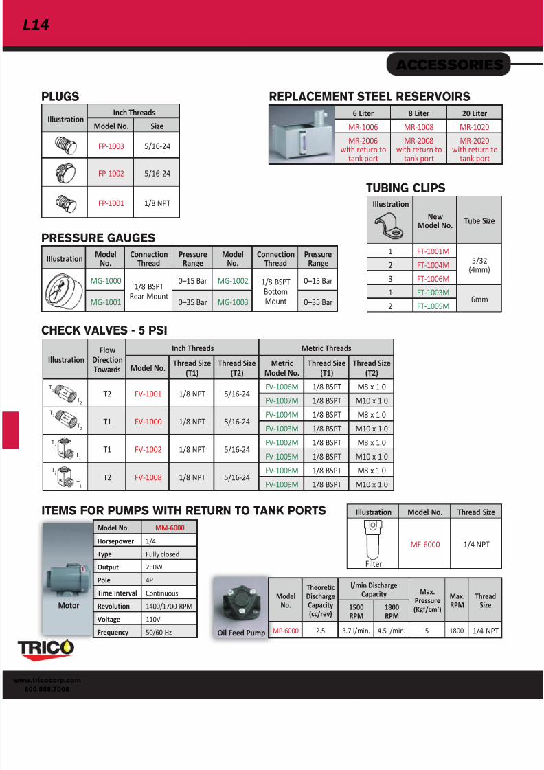
ACCESSORIES
PLUGS
PRESSURE GAUGES
TUBING CLIPS
REPLACEMENT STEEL RESERVOIRS
Model No. MM-6000
Horsepower 1/4
Type Fully closed
Output 250W
Pole 4P
Time Interval Continuous
Revolution 1400/1700 RPM
Voltage 110V
Frequency 50/60 Hz
ITEMS FOR PUMPS WITH RETURN TO TANK PORTS
Oil Feed Pump
Motor
CHECK VALVES - 5 PSI
T2
T2
T2
T2
T1
T1
T1
T1
6 Liter 8 Liter 20 Liter
MR-1006 MR-1008 MR-1020
MR-2006with return to
tank port
MR-2008with return to
tank port
MR-2020with return to
tank port
Illustration Model No. Thread Size
Filter
MF-6000 1/4 NPT
ModelNo.
TheoreticDischargeCapacity(cc/rev)
l/min DischargeCapacity Max.
Pressure(Kgf/cm2)
Max.RPM
ThreadSize1500
RPM1800RPM
MP-6000 2.5 3.7 l/min. 4.5 l/min. 5 1800 1/4 NPT

7/18/2019 Trico Lubricacion Centralizada
http://slidepdf.com/reader/full/trico-lubricacion-centralizada 16/22
L
www.tricoco
800.558.7
TECHNICAL INFORMATION
VISCOSITY OF OIL
LUBRICANTS
Trico pumps are designed to dispense mineralbased lubricants with a viscosity range of 30-250centistokes or 150 - 1200 SUS. New clean oilis always recommended and users shouldcheck with machine manufacturers for therecommended lubricant for their equipment.
OIL SELECTION FOR
CENTRAL LUBRICATION
Many manufacturers of equipment that usecentral lubrication systems will recommendthe specific lubricating oil to be used. If aparticular oil is not recommended, thenseveral factors must be considered. Load andfriction elements of surfaces to be lubricatedare a primary consideration. The ambienttemperature during machine operation,and also the speed of the equipment aresignificant factors. The viscosity of the oil isa measure of how the oil flows at a giventemperature. Both the temperature andthe operating pressure will determine the
resistance to flow of the oil. As the pressureor temperature increases, the oil delivery rateis increased.
Always use clean oil in central lubricationsystems. Contamination in the oil willsignificantly shorten the life of the surfacesbeing lubricated. Synthetic lubricants tendto be more stable than mineral based ones.However, some synthetic lubricants can attackstandard seal material, and seal compatibilitymust be checked before using any oil type.
To insure the correct choice of lubricating oil,consult the machinery manufacturer or OEM.
TEMPERATURE VISCOSITY RELATIONSHIP
V i s c o s i t y - S U S
Operating Temp. - ºF
7,000
6,000
5,000
4,000
3,000
2,000
1,000
70 80 90 100
SAE 10
SAE 20
SAE 30
SAE 40
SAE 50
SAE 60
SAE 70
METRIC CONVERSION CHART
1 oz. 30 ml./30cc.
1 pt. .473 liters
1 qt. .946 liters
1/2 gal. 1.89 liters
1 gal. 3.785 liters

7/18/2019 Trico Lubricacion Centralizada
http://slidepdf.com/reader/full/trico-lubricacion-centralizada 17/22
L16
ww.tricocorp.com
800.558.7008
USING THE SYSTEM DESIGN WORKSHEET
INSTRUCTIONS - Follow the instructions as listed below using the worksheet. The worksheet is designed for cyclic
systems. For assistance with continuous systems, contact Trico.
STEP 1 - List the lubrication points in the system.
In column A, list each lubricant point by description.
STEP 2 - Determine the lubrication required at each point.
In column B, write the lubrication delivery required at each point in cc/hr. Enter the total delivery required in the total box. Refer tothe specification from the machinery manufacturer whenever possible. The Lubricating Calculations table below can be used as aguide in determining lubrication requirements.
STEP 3 - Determine the flow ratios for each lubrication point.
Find the lubrication point requiring the least amount of oil. Divide each of the !Lube Delivery Req"d# values by that amount. Enterthese values in column C. This will determine the ratio of lubrication required between all of the lubrication points.
LUBRICATING CALCULATIONS
If the amount of lubrication needed is not specified by the equipment manufacturer, this table can be used as a guide.
Illustration Application Oil Required in cc/hour
Ball Bearings .10 x bearing diameter (in.) x number of rows or bearings.04 x bearing diameter (cm.) x number of rows or bearings
Plain Bearings.15 x bearing shaft diameter (in.) x bearing length (in.)
.023 x bearing shaft diameter (cm.) x bearing length (cm.)
Flat Sides.04 x [slide length (in.) + travel (in.)] x slide width (in.)
.006 x [slide length (cm.) + travel (cm.)] x slide width (cm.)
Cylindrical Slides.15 x [slide length (in.) + travel (in.)] x slide diameter (in.)
.023 x [slide length (cm.) + travel (cm.)] x slide diameter (cm.)
Ball Bearing Slides.03 x slide length (in.) x number of slides or rows
.012 x slide length (cm.) x number of slides or rows
Cams.08 x surface area (sq. in.)
.013 x surface area (sq. cm.)
Gears.30 x gear pitch diameter (in.) x face width (in.)
.046 x gear pitch diameter (cm.) x face width (cm.)
Chains.05 x length of chain (in.) x width (in.)
.008 x length of chain (cm.) x width (cm.)

7/18/2019 Trico Lubricacion Centralizada
http://slidepdf.com/reader/full/trico-lubricacion-centralizada 18/22
L
www.tricoco
800.558.7
USING THE SYSTEM DESIGN WORKSHEET
CHART 1 CHART 2 CHART 3
SIZING CHARTS
STEP 4 - DETERMINE WHICH OF THE THREE SIZING CHARTS TO USE.
Find the highest ratio listed in Column C. If the highest value is 48 or less, then use sizing chart 1 in step 5. If it is between 49 and 96,then use chart 2 in step 5. If it is between 97 and 192, then use chart 3 in step 5.
STEP 5 - MULTIPLIER, FLOW RATE, AND Q VALUE AMOUNTS.
Referring to Sizing Chart 1, 2, or 3, fill in the appropriate multiplier, flow rate, and Q value for each lubrication point. Enter the totalsfor the multipliers and Q values in the total boxes.
STEP 6 - CALCULATE ACTUAL DELIVERY FOR EACH LUBRICATION POINT.
To confirm the actual delivery that each lubrication point will receive, the following calculation is done. For each lubricationpoint, divide the total oil required in the system by the total of all the multipliers. Multiply that number by the multiplier for thatlubrication point. Record the amount in column G.
STEP 7 - CHECK FOR FLOWABILITY.
Divide the viscosity of the oil (SUS at operating temperature), by the total of all the Q values for the system. If the result of thatcalculation is 61 or less then the system has flowability. If the result is higher than 61, larger meter units are required. Increase eachmeter unit flow rate value by one size. Add the new Q values that correspond, and repeat the calculation. Continue to do this untilthe flowability calculation is 61 or less.
STEP 8 - SELECT THE APPROPRIATE PUMP.
Using the pump selection chart, select a pump best suited for the application.
STEP 9 - CHOOSE THE APPROPRIATE METER UNITS.
Column E has the designated flow rate for each of the meter units. Select the meter unit with thread configuration best suited foreach application point.
Ratio
Multip. FlowRate !Q"ValueFrom To
1.00 1.50 1 0 5
1.51 3.00 2 1 10
3.01 6.00 4 2 20
6.01 12.00 8 3 40
12.01 24.00 16 4 80
24.01 48.00 32 5 160
RatioMultip. Flow
Rate!Q"
ValueFrom To
1.00 1.50 1 00 2.5
1.51 3.00 2 0 5
3.01 6.00 4 1 10
6.01 12.00 8 2 20
12.01 24.00 16 3 40
24.01 48.00 32 4 80
48.01 96.00 64 5 160
RatioMultip. Flow
Rate!Q"
ValueFrom To
1.00 1.50 1 3/0 1.25
1.51 3.00 2 00 2.50
3.01 6.00 4 0 5
6.01 12.00 8 1 10
12.01 24.00 16 2 20
24.01 48.00 32 3 40
48.01 96.00 64 4 80
96.01 192.00 128 5 160
C D E F
C D E F
C D E F

7/18/2019 Trico Lubricacion Centralizada
http://slidepdf.com/reader/full/trico-lubricacion-centralizada 19/22
L18
ww.tricocorp.com
800.558.7008
SYSTEM DESIGN WORKSHEET
Machine:_______________________________________________________________________
Lubricant:_______________________________ Viscosity:__________________ SUS at______°F Oper. Temp.
Prepared By:_______________________________________________ Date:_________________
Please visit our website for assistance on designing a central lubrication system at
www.tricocorp.com/technical/central-lub-worksheet.aspx.
LubePointNo.
Lubricant Point DescriptionLube
DeliveryReq#d cc/hr
RatioBetween
LubePoints
Multiplier Flow Rate Q ValueActual
Deliverycc/hr
1
2
3
45
6
7
8
9
10
11
12
13
1415
16
17
18
19
20
Delivery Total Multiplier Total Q Value Total
A
B C
D E F G
HELPFUL TIP:The above worksheet is for
designing an automatic cyclic
system. When designing a
continuous system, please
contact Trico’s customer
service for assistance.

7/18/2019 Trico Lubricacion Centralizada
http://slidepdf.com/reader/full/trico-lubricacion-centralizada 20/22
L
www.tricoco
800.558.7
PRODUCT SELECTION CHARTS
INSTRUCTIONSFind the Flow Rate value foreach lubrication point. This
corresponds to the flowrate values in the MeterUnits chart. Select themounting configuration bestsuited for the application.Additional informationregarding the mountingconfiguration is found onthe opposite page.
CONTROL UNITS
F L OW DI R E C T I ON
F L O
W DI R E C T I ON
INSTRUCTIONS Find the total oil required for all lubrication points. Select a pump that is in the desired flowrange. Refer to the Trico catalog for information on the specific features of the different pumps.
SELECTION CHART FOR AUTOMATIC CYCLIC PUMPS
METER UNITS
FlowRate
5/16-24x
5/16-24
5/16-24x
1/8 NPT
1/8 NPTx
1/8 NPT
M8 x 1.0x
M8 x 1.0
M8 x 1.0x
1/8 BSPT
1/8 BSPTx
1/8 BSPT
3/0 DSM-3/0 DCM-3/0 DTM-3/0 $ $ $
00 DSM-00 DCM-00 DTM-00 DSM-00M DCM-00M DTM-00M
0 DSM-0 DCM-0 DTM-0 DSM-0M DCM-0M DTM-0M
1 DSM-1 DCM-1 DTM-1 DSM-1M DCM-1M DTM-1M
2 DSM-2 DCM-2 DTM-2 DSM-2M DCM-2M DTM-2M
3 DSM-3 DCM-3 DTM-3 DSM-3M DCM-3M DTM-3M
4 DSM-4 DCM-4 DTM-4 DSM-4M DCM-4M DTM-4M
5 DSM-5 DCM-5 DTM-5 DSM-5M DCM-5M DTM-5M
FlowRate
5/16-24
x5/16-24
5/16-24
x1/8 NPT
1/8 NPT
x1/8 NPT
M8 x 1.0
xM8 x 1.0
M8 x 1.0
x1/8 BSPT
1/8 BSPT
x1/8 BSPT
5/0 $ DCC-5/0 DTC-5/0 $ $ $
4/0 DSC-4/0 DCC-4/0 DTC-4/0 $ $ $
3/0 DSC-3/0 DCC-3/0 DTC-3/0 $ $ $
00 DSC-00 DCC-00 DTC-00 $ $ $
0 DSC-0 DCC-0 $ $ $ $
1 DSC-1 DCC-1 DTC-1 DSC-1M DCC-1M DTC-1M
2 DSC-2 DCC-2 DTC-2 DSC-2M DCC-2M DTC-2M
3 $ $ DTC-3 DSC-3M DCC-3M $
4 DSC-4 DCC-4 $ DSC-4M DCC-4M $
5 DSC-5 $ DTC-5 $ DCC-5M $
0 1 2 3 6 12 15 18 24 36 60 72 120 360 500
PE-1002-60PE-1202-60
PE-1002-30PE-1202-30
PE-1002-15PE-1202-15
PE-1002-10PE-1202-10
PE-1002-05PE-1202-05
PE-1002-03
PE-1202-03
PE-2002-06, PE-2202-06
PE-2002-15, PE-2202-15
PE-3003, PE-3006, PE-3020, PE-3203, PE-3206, PE-3208, PE-3220, PE-2402
P u m p T y p
e s
Oil Required - cc/hr

7/18/2019 Trico Lubricacion Centralizada
http://slidepdf.com/reader/full/trico-lubricacion-centralizada 21/22
L20
ww.tricocorp.com
800.558.7008
DISTRIBUTION NETWORK DESIGN
Selecting the distribution network components begins with a sketch or layout of the system. Hardware will be different whenthe lubrication points are some distance apart or are close together. Many systems will be combinations of distant and closelubrication points. The general sequence is A) Select the pump location B) determine how your meter units or control units willmount at each point and C) develop interconnecting plumbing.
A. Pump Location Several key considerations are: 1. Install the pump to be visible to the machine operator or maintenance person. This will simplify checking lubricant levels. 2. Make sure that there is easy access for refilling the reservoir. 3. Access to electricity for automatic pumps should be convenient and safe. 4. Generally, the pump is mounted lower than the majority of the points being lubricated to avoid trapped air.
B. Meter Unit or Control Unit Installation There are three mounting options to choose from in both meter units and control units. 1. Direct Mounting In these applications, the meter or control unit is connected directly to the lubrication point and a single line is connected
to it (fig. 1). One end of the meter or control unit is NPT or BSPT and the other end is a 5/16-24 or metric straight thread.
2. Tee Mounting In these applications, the meter or control unit is connected directly to the lubrication point and a junction is connected
on the other end (fig. 2). Both ends of the meter or control unit are NPT or BSPT.
DTM Meter Unitor
DTC Control Unit
JH Series Junction
Figure 2
TB-12 or TC-12Metal Tubing
DCM Meter Unitor
DCC Control Unit
TN-12Plastic Tubing
FM-3000 Nut FM-3000 Nut
FS-1000 Sleeve FS-1002 Sleeve
Figure 1
5/16-24
NPT
NPT
NPT

7/18/2019 Trico Lubricacion Centralizada
http://slidepdf.com/reader/full/trico-lubricacion-centralizada 22/22
L
DISTRIBUTION NETWORK DESIGN
3. Remote Mounting In these applications, the meter or control unit is not connected to the lubrication point. One end of the meter or
control unit is connected to a junction, and the other end is connected to tubing that goes to the lubrication point(fig. 3). Both ends of the meter or control unit are 5/16-24 or metric straight threads.
C. Interconnecting PlumbingThere are several considerations to make when connecting a central lubrication system.
1. Tubing Type - Metal or plastic tubing are the 2 choices available. When using metal tubing, copper tubing is the easiestto install. Steel is stronger, but more difficult to install.
2. Hoses - When connecting lubrication points that move, the use of a hose is recommended. Allow adequate hose length
to prevent kinking, stretching, or twisting. 3. Tubing Fittings - Refer to figures 1, 2, and 3 for examples of how the tubing fittings connect. When connecting tubing
to a female thread, use the FM-1000 series bushings in place of the FM-3000 series nuts (fig. 4).
4. Pressure gauges - Pressure gauges should be installed in central lubrication systems to verify that adequate oil pressureis getting to each lubricant point. Depending on the size of the system, one or more gauges may be installed atdifferent points. A gauge installed at the furthest point from the pump is useful in determining if the entire system isreceiving adequate oil pressure.
5. Check valves - Check valves are used to hold pressure in a line and prevent dripping and leaking. Meter units containinternal check valves, and control units do not need check valves because of the constant flow. Separate check valvescan be installed when the meter unit is not located at the point of lubrication. Installing the check valve between themeter unit and the lubricant point will maintain an oil supply in the lubrication line.
TB-12 or TC-12Metal Tubing
TN-12Plastic Tubing
FS-1000 SleeveFS-1002 Sleeve
J, JD or JS Series
Junction
FM-3000 Nut
FM-3000 Nut
Figure 3
5/16-24
5/16-24
5/16-24 Female Threads
FS-1000 Sleeve
FM-1000 Bushing
TB-12 or TC-12Metal Tubing
Figure 4


