28
Tridak ® Model 2200 User Guide Cartridge Filler with Disposable Fluid Path Technology ■ Instructions for Safe Use ■ Setup and Operation ■ Maintenance ■ Ordering Spare Parts and Accessories
Tridak® Model 2200 User Guide Cartridge Filler with Disposable Fluid Path Technology ■ Instructions for Safe Use
■ Setup and Operation
■ Maintenance
■ Ordering Spare Parts and Accessories

2 Tridak® Model 2200 Cartridge Filling System User Guide
About Dymax
Light-curable materials as well as systems for light curing, fluid dispensing, and fluid packaging.
Dymax manufactures a wide variety of light-curable oligomers, adhesives, and coatings as well as a complete line of manual and
automatic fluid dispensing systems, light-curing systems, and fluid packaging equipment.
Our Tridak® brand fluid packaging systems are designed for use in numerous industries, including industrial, medical, dental,
pharmaceutical, and food preparation. These filling systems provide significant productivity gains over manual and other more
complicated and costly filling methods. The equipment is suited for all industry standard packaging as well as custom molded syringes and
cartridges. We also possess the capability to fabricate nozzles and multi-port dispensing manifolds that perfectly match the packages
being filled. Single- and dual-component materials can be packaged in seconds, one at a time, or in multiples for higher volume
throughput. The equipment accommodates various mix ratios. High-pressure filling equipment is available for packaging highly filled
materials in tiny syringes or compoules.
Please note that most filling system applications are unique. Dymax does not warrant the fitness of the product for the intended
application. Any warranty applicable to the product, its application and use is strictly limited to that contained in the Dymax standard
Conditions of Sale. Dymax recommends that any intended application be evaluated and tested by the user to insure that desired
performance criteria are satisfied. Dymax is willing to assist users in their performance testing and evaluation.

3 Tridak® Model 2200 Cartridge Filling System User Guide
Contents Introduction .................................................................................................................................................... 4 Introduction to the User Guide ................................................................................................................................................. 4
Where to Get Help .................................................................................................................................................................... 4
Safety .............................................................................................................................................................. 4 General Safety Considerations .................................................................................................................................................. 4
Specific Safety Considerations .................................................................................................................................................. 5
Personal Protective Equipment ................................................................................................................................................ 5
Potential Hazards ...................................................................................................................................................................... 5
Product Overview ........................................................................................................................................... 6 Description of the Model 2200 Cartridge Filler ......................................................................................................................... 6
Special Features and Benefits of the Model 2200 Cartridge Filler ............................................................................................ 6
Description of Main Components ............................................................................................................................................. 7
Assembly and Setup ........................................................................................................................................ 8 Unpacking and Inspecting Your Shipment ................................................................................................................................ 8
Parts Included in Model 2200 Cartridge Filler ........................................................................................................................... 9
Preparing the System for Use .......................................................................................................................... 9 Initial Preparation ..................................................................................................................................................................... 9
Preparing the Plastic Reservoir Liner ...................................................................................................................................... 11
Installing the Nozzle ................................................................................................................................................................ 12
Setting the Fill Height .............................................................................................................................................................. 13
Turning on the Main Air .......................................................................................................................................................... 14
Filling the Plastic Reservoir Liner ............................................................................................................................................ 14
Turning on the Air to the Tank ................................................................................................................................................ 15
Priming the System ................................................................................................................................................................. 15
Operation (Automatic Filling) ........................................................................................................................ 16
Removing the Tank Top after Being Pressurized ........................................................................................... 17
System Adjustments ..................................................................................................................................... 17 Valve Adjustments .................................................................................................................................................................. 17
Cartridge Adjustments ............................................................................................................................................................ 20
Maintenance ................................................................................................................................................. 21
Troubleshooting ............................................................................................................................................ 21
Spare Parts and Accessories .......................................................................................................................... 22
Specifications ................................................................................................................................................ 23 System Specifications.............................................................................................................................................................. 23
Warranty ...................................................................................................................................................... 25
Index ............................................................................................................................................................. 26
4 Tridak® Model 2200 Cartridge Filling System User Guide
Introduction
Introduction to the User Guide
This guide describes how to assemble, use, and maintain the Tridak® Model 2200 Cartridge Filling System
safely and efficiently. The filling system described in this user guide consists of the Tridak® Model 2200
Cartridge Filler and a 10-Gallon Drop-In Reservoir Tank (sold separately).
Intended Audience
This user guide was prepared for experienced process engineers, technicians, and manufacturing personnel. If
you are new to filling systems and do not understand the instructions, contact Application Engineering to have
your questions answered before using the equipment.
Where to Get Help
Additional resources are available to ensure a trouble-free experience with our products:
■ Detailed product information on www.tridak.com
■ Customer Support and Application Engineering teams are available in the United States, Monday through
Friday, from 8:00 a.m. to 5:30 p.m. Eastern Standard Time. You can also email us at [email protected].
Please see the back cover of this user guide for worldwide contact information.
Safety WARNING! If you use this filling system without first reading and understanding the
information in this user guide, injury can result. To reduce the risk of injury, read and ensure you understand the information in this user guide before assembling and operating a Tridak filling system.
General Safety Considerations
All users of Tridak filling equipment should read and understand this user guide before assembling and using
the equipment.
To learn about the safe handling and use of dispensing and packaging fluids, obtain and read the MSDS for
each fluid before using the fluid.
5 Tridak® Model 2200 Cartridge Filling System User Guide
Specific Safety Considerations
Using Safe Operating Pressures
Pressurizing the components in the system beyond the maximum recommended pressure can result in the
rupturing of components and serious personal injury. To minimize the risk of rupturing components and
injury, do not exceed the maximum operating pressure of the components in your filling system.
Recommended Operating Pressures
The recommended operating pressure of the Model 2200 Cartridge Filler is 60-80 psi [0.41-0.55 MPa,
4.1-5.5 bar]. The maximum recommended working pressure of the 10 Gallon Drop-In Reservoir Tank is 65 psi
[0.45 MPa, 4.9 bar]. The maximum rated pressure of the reservoir is 100 psi [0.69 MPa, 6.9 bar]. See system
specifications on page 23. If a different tank is to be used with the Model 2200 Cartridge Filler, refer to the
specific reservoir manual for the recommended pressure specifications.
Preventing Injection Injury
Discharging fluids or compressed air with a nozzle against your skin can cause very serious injection injury. To
minimize the risk of injection injury, do not place the filling nozzle in contact with your skin.
Personal Protective Equipment
Operators are recommended to wear any personal protective equipment specified by their company’s safety
policy for the materials used during filling. Personal protective equipment should be in place and used at all
times before pressurizing the system and when handling any potentially hazardous materials.
Potential Hazards
Equipment Misuse
WARNINGS! This equipment is for professional use only. Serious injury can result from high-
pressure fluids. To reduce the risk of injury, read and ensure you understand the information in this user guide before assembling and operating the Tridak filling system and its accessories.
Use the equipment only for its intended purpose. If you are ever unsure, call Tridak.
Do not alter this equipment. Use only Tridak parts.
Check equipment daily. Repair or replace worn or damaged parts immediately.
Comply with all applicable local, state, and national fire and safety regulations.
!
6 Tridak® Model 2200 Cartridge Filling System User Guide
Fire and Explosion
WARNINGS! Poor ventilation, open flames, or sparks can cause a hazardous condition and
result in a fire or explosion and serious injury.
Do not install the Tridak Model 2200 Cartridge Filler in a hazardous location.
Provide fresh air ventilation to avoid buildup of flammable fumes.
Eliminate all ignition sources such as cigarettes.
Chemical
WARNINGS! Hazardous fluid or toxic fumes can cause serious injury or death if inhaled,
swallowed, or splashed in the eyes or on the skin.
Always wear protective eyewear, gloves, and clothing as recommended by the fluid manufacturer.
Know the specific hazards of the fluid you are using.
Store hazardous fluid in an approved container. Dispose of hazardous fluid according to all local, state, and national guidelines.
Product Overview
Description of the Model 2200 Cartridge Filler
The Tridak® Model 2200 Cartridge Filler offers void-free, accurate, and consistent filling of most single- and
dual-component cartridges and syringes. This filler utilizes a bottom-up filling process combined with a special
low-clearance nozzle design to eliminate air entrapment and provide a void-free, accurate fill each time.
Special Features and Benefits of the Model 2200 Cartridge Filler
The Model 2200 Cartridge Filler is engineered for precise performance and long service life. Key features
include:
■ Adjustable fill speed and fill level with consistent accuracy
■ Disposable fluid path valve technology which eliminates cross-contamination and minimizes clean-up and
downtime during product changeover
■ Fills single- and two-component cartridges and syringes
■ Fills one side at a time to prevent cross contamination
■ Bottom-up filling process eliminates air entrapment
■ Dimensions (W x D x H) - 16.25" x 16.25" x 27" [41.28 cm x 41.28 cm x 68.58 cm]

7 Tridak® Model 2200 Cartridge Filling System User Guide
Description of Main Components
Figure 1. Main Components of a Model 2200 System (Front View with 10 Gallon Drop-In Reservoir Tank)
Clamp Handle Prime Button
Follower Plate
Base Plate
Relief Valve
Top Plate
Valve Body
Counterbalance Control
Knob
Nozzle Mount
Level Adjustment Screw
Clamps
Tank Cover
Tank
Tank Guide Pins
Footswitch
Tank Stabilizer Handles

8 Tridak® Model 2200 Cartridge Filling System User Guide
Figure 2. Main Components of the Model 2200 Cartridge Filler (Rear View with Back Cover Removed, No Tank)
Assembly and Setup
Unpacking and Inspecting Your Shipment
When your Model 2200 Cartridge Filler arrives, inspect the box and notify the shipper of any damage
immediately.
Open each box and check for equipment damage. If parts are damaged, notify the shipper and submit a claim
for the damaged parts. Contact Dymax so that new parts can be shipped to you immediately.
Your shipment will contain the parts listed below. If parts are missing, contact your local Dymax representative
or Dymax Customer Support to resolve the problem.
Lift Platform Assembly
Top Plate
Counterbalance
Cylinder
Front Plate
Prime
Air Logic Valves
Cylinder Rod Coupling
Base Plate
Bumper Assembly
Tank Guide Pins
Counterbalance
Regulator
Filter Assembly
Slide Assembly
Proximity Valve,
Level Adjustment
Assembly
Proximity Valve
Actuating Screw
Air Manifold
(Located Behind Inlet
Panel Assembly)
Inlet Panel Assembly

9 Tridak® Model 2200 Cartridge Filling System User Guide
Parts Included in Model 2200 Cartridge Filler
■ Model 2200 Cartridge Filling System
■ Footswitch
■ Printed user manual
Preparing the System for Use
Initial Preparation
Note: The following instructions are based on the Model 2200 System with a 10 Gallon Drop-In Reservoir Tank
and a Tank Liner Assembly. Contact Customer Support for installation support with a different reservoir.
Secure the system to a permanent workbench using the 4 bolts supplied. Refer to Figure 3 for the correct
pattern and hole size.
WARNING! It is important that the Model 2200 system is properly secured to the workbench
in order to operate the system safely.
Figure 3. Mounting Patterns and Hole Size
15.25
15.25
1.00 MINIMUM DISTANCE TO THE
FRONT EDGE OF THE WORKBENCH
4X .41 DIAMETER THRU
FRONT EDGE OF WORKBENCH
1. Attach the Footswitch (if not already installed). The airline labeled "OUT" on the machine's Inlet Panel
(Figure 4) goes to the fitting marked "IN" on the Footswitch. The airline labeled "IN" on the system’s Inlet
Panel (Figure 4) goes to the fitting marked “OUT" on the Footswitch.
10 Tridak® Model 2200 Cartridge Filling System User Guide
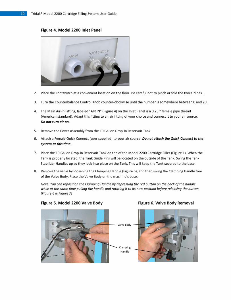
Figure 4. Model 2200 Inlet Panel
2. Place the Footswitch at a convenient location on the floor. Be careful not to pinch or fold the two airlines.
3. Turn the Counterbalance Control Knob counter-clockwise until the number is somewhere between 0 and 20.
4. The Main Air-In Fitting, labeled "AIR IN" (Figure 4) on the Inlet Panel is a 0.25 " female pipe thread
(American standard). Adapt this fitting to an air fitting of your choice and connect it to your air source.
Do not turn air on.
5. Remove the Cover Assembly from the 10 Gallon Drop-In Reservoir Tank.
6. Attach a Female Quick Connect (user supplied) to your air source. Do not attach the Quick Connect to the
system at this time.
7. Place the 10 Gallon Drop-In Reservoir Tank on top of the Model 2200 Cartridge Filler (Figure 1). When the
Tank is properly located, the Tank Guide Pins will be located on the outside of the Tank. Swing the Tank
Stabilizer Handles up so they lock into place on the Tank. This will keep the Tank secured to the base.
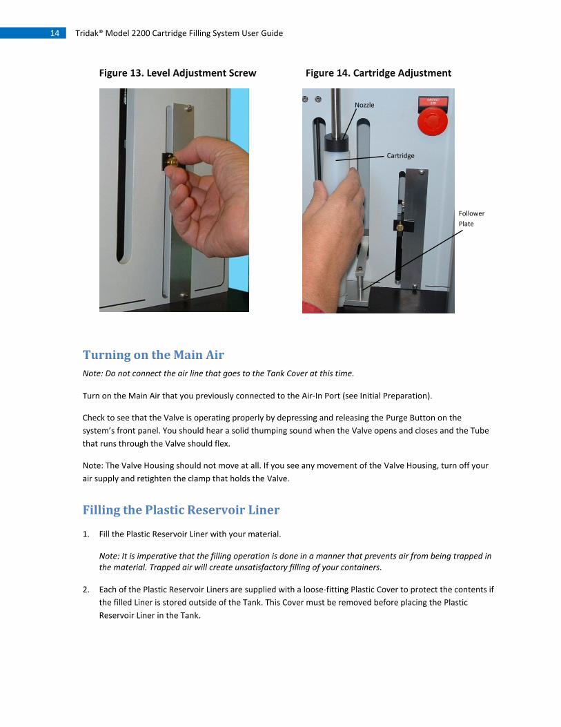
8. Remove the valve by loosening the Clamping Handle (Figure 5), and then swing the Clamping Handle free
of the Valve Body. Place the Valve Body on the machine’s base.
Note: You can reposition the Clamping Handle by depressing the red button on the back of the handle while at the same time pulling the handle and rotating it to its new position before releasing the button. (Figure 6 & Figure 7)
Figure 5. Model 2200 Valve Body
Figure 6. Valve Body Removal
Valve Body
Clamping
Handle

11 Tridak® Model 2200 Cartridge Filling System User Guide
Preparing the Plastic Reservoir Liner
There are two basic procedures for preparing the plastic reservoir liner for use. Which method is used
depends solely on which is more convenient for the user. The first method requires the user to place the tube
on the tubing adapter before placing the plastic reservoir liner in the tank. The second method requires the
user to attach the tubing after the plastic reservoir liner is in the tank.
Note: The tubing must be pre-cut to a length of 7.25 +/- .03 inches.
Method 1. Placing the tubing on the tube adapter before placing the liner in the tank
1. Slide the Tube provided over the end of the Tube Adapter (Figure 7).
3. Insert the plastic Reservoir Liner Assembly into the Tank. The large diameter of the Tube Adapter must go
through the hole in the Seal Adapter at the bottom of the Tank. Please note that the O-Ring located
within this adapter should be lubricated occasionally to insure easy insertion and removal of the Reservoir
Liner.
Method 2. Placing the tubing on the tube adapter after placing the liner in the tank
1. Insert the plastic Reservoir Liner Assembly into the Tank. The large diameter of the Tube Adapter must go
through the hole in the Seal Adapter at the bottom of the Tank (Figure 9). Please note that the
O-Ring located within this adapter should be lubricated occasionally to insure easy insertion and removal
of the Reservoir Liner.
2. Slide the Tube provided over the end of the Tube Adapter (Figure 9).
Figure 7. Tank Liner: Tube Adapter
Figure 8. Tank Liner: Collar
Seal Adapter
Tube Adapter
Reservoir Liner
Tube
Tube Adapter

12 Tridak® Model 2200 Cartridge Filling System User Guide
Figure 9. Tank Liner: Method 2
Installing the Nozzle
The proper nozzle should be placed into position by following this procedure.
1. Loosen the Thumbscrew located on the side of the Nozzle Block by rotating it counter-clockwise
(Figure 10).
2. Insert the Nozzle from the bottom of the Nozzle Block (Figure 11). At the same time, guide the Tube from
the Tank into the opening on the top of the Nozzle. You will feel resistance as the Tube goes by the O-Ring.
This O-Ring should be lubricated occasionally (Figure 12).
3. Push the Nozzle upwards until the Retaining Ring stops against the Nozzle Block. While holding it in
position, tighten the Thumbscrew (Figure 12).
4. Place the Valve into its proper position. The pin in the body must be aligned with the hole in the Pivot
Mount.
5. Swing the Clamp Handle into position and tighten.
Figure 10. Nozzle Block
Figure 11. Nozzle Installation
Seal Adapter
Tube
Tube Adapter
Nozzle
Block
Nozzle
Block
Nozzle

13 Tridak® Model 2200 Cartridge Filling System User Guide
Figure 12. Nozzle Assembly
Setting the Fill Height
Set the level to which the cartridge will be filled (i.e., the point where the valve shuts off the flow of material
into your cartridge) using the following instructions:
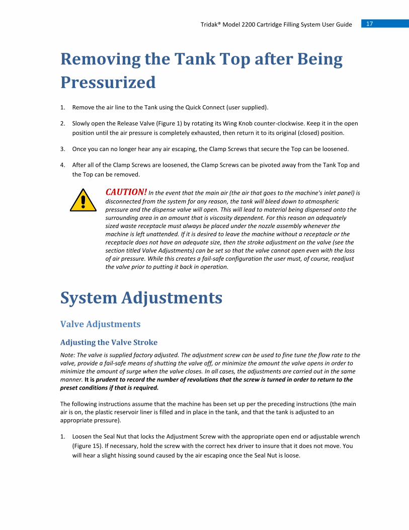
1. Loosen the Level Adjustment Locking Screw by turning it counter-clockwise (Figure 13).
2. Slide the Level Adjustment Screw to the halfway point in the slot. When it slides in, tighten the Locking
Screw by rotating it clockwise (Figure 13).
3. Grasp the Follower Plate (Figure 1) and slowly move the plate up and down. If you listen very carefully you
will hear a gentle click sound as it passes the position where the dispense valve will stop the flow of
material.
4. Place the Cartridge onto the Nozzle and let its bottom rest on the Follower Plate (Figure 14).
5. Move the Follower Plate (with the Cartridge resting on it) up the Nozzle until the bottom of the Nozzle is
at the level that you want the fluid height within the Cartridge. Keep the Cartridge and Follower Plate in
this position while you loosen the Level Adjustment Screw. Slide the Level Adjustment Screw up and down
while listening for the clicking sound that you observed earlier. When this sound is heard, tighten the
screw to maintain its position. Move the Cartridge up and down the Nozzle by moving the Follower Plate
up and down. Make sure that the cartridge is resting on the Follower Plate and confirm that the clicking
sound is occurring at the proper position.
6. Bring the Follower Plate and Nozzle back down to the bottom position and remove the Cartridge.
Note: The initial adjustment is just an approximation and must be refined by making small adjustments to
the Level Adjustment after observing the actual fill levels once you begin automatically filling the
Cartridges.
Nozzle
Flexible Tube
14 Tridak® Model 2200 Cartridge Filling System User Guide
Figure 13. Level Adjustment Screw
Figure 14. Cartridge Adjustment
Turning on the Main Air
Note: Do not connect the air line that goes to the Tank Cover at this time.
Turn on the Main Air that you previously connected to the Air-In Port (see Initial Preparation).
Check to see that the Valve is operating properly by depressing and releasing the Purge Button on the
system’s front panel. You should hear a solid thumping sound when the Valve opens and closes and the Tube
that runs through the Valve should flex.
Note: The Valve Housing should not move at all. If you see any movement of the Valve Housing, turn off your
air supply and retighten the clamp that holds the Valve.
Filling the Plastic Reservoir Liner
1. Fill the Plastic Reservoir Liner with your material.
Note: It is imperative that the filling operation is done in a manner that prevents air from being trapped in the material. Trapped air will create unsatisfactory filling of your containers.
2. Each of the Plastic Reservoir Liners are supplied with a loose-fitting Plastic Cover to protect the contents if
the filled Liner is stored outside of the Tank. This Cover must be removed before placing the Plastic
Reservoir Liner in the Tank.
Cartridge
Nozzle
Follower
Plate

15 Tridak® Model 2200 Cartridge Filling System User Guide
3. Place the Follower Plate on top of the material (handle side toward the open end of the Plastic Reservoir
Liner) and push it down until it is seated firmly on the fluid’s surface. Do not push hard enough to allow
any fluid to come around the sides and flow onto the top surface.
Note: The Follower Plate might not be needed on a low-viscosity material (one that self-levels quickly).
4. Place the Tank Cover on the tank. Swing the Clamps into position and rotate the Clamp Handles clockwise
until the screw ends are firmly seated against the Cover. It is good practice to tighten opposite Clamps in
sequence (i.e. tighten the Clamp at 12 o'clock, then the one at 6 o'clock, then the one at 9 o'clock
followed by the one at 3 o'clock, and so on. Follow this pattern until all are tightened. Moderate hand
tightening force is adequate. Never force the Clamps or use tools to tighten).
5. Turn the knob on the Pressure Regulator (located on the top of the Reservoir Cover) counter-clockwise
until it stops.
Turning on the Air to the Tank
Connect the air line that goes to the Tank using the Quick Connect (user supplied) that has been previously
connected to your Main Air Source (Initial Preparation, Step 6).
Without a Cartridge in place, turn the Counterbalance Knob clockwise until the Lift Plate starts to rise.
Continue to slowly turn the knob. Only turn the knob enough so that the Follower Plate is able to travel to its
full up position.
Lower the Follower Plate by hand and place a Cartridge into position resting on the platform and over the
Nozzle (you will probably have to lightly hold the Cartridge in its initial position). Now turn the Counterbalance
Knob clockwise so that the platform can lift itself and the Cartridge as far as it can go.
Note: On some Cartridges this will be until the Nozzle stops on the bottom of the Cartridge and on other Cartridges (particularly long ones) this will be until the slide completes its travel (the Nozzle will not touch the bottom of the Cartridge). Both are correct.
Manually lower the Lift Plate and Cartridge. Remove the Cartridge.
Priming the System
CAUTION! Never operate the machine without a waste receptacle or Cartridge in its proper
position under the Nozzle.
Slowly turn the knob on the Pressure Regulator (located on the top of the Tank) clockwise until the Pressure
Gauge reads approximately 10 psi. If the Tank volume is large, allow adequate time for the pressure to build
up and stabilize.
Lower the Lift Plate manually and hold an adequately sized waste receptacle under the Nozzle.
Depress the Prime Button on the front panel and observe the material flow from the Nozzle. This may take a
few seconds since material must fill the Tubing. If after an adequate length of time the material is not flowing,
adjust the Pressure Regulator on the Tank upwards by 5 psi and repeat the procedure.

16 Tridak® Model 2200 Cartridge Filling System User Guide
Once the material is flowing, allow it to flow until it is free of any air. This can be done in one or several shots
depending on the size of your waste receptacle.
When the flow is air free, continue to adjust the pressure on the Tank, either up or down, until you achieve
the desired flow rate.
Operation (Automatic Filling) Note: This section presumes that all of the preceding steps, in each of the sections, have been followed.
1. Lower the Follower Plate manually. Place a Cartridge over the Nozzle with the end resting on the Follower
Plate and allow it to move up as far as the Slide or Nozzle will allow.
Note: Since all of the adjustments at this point have been preliminary in nature, a slight upwards force on the Follower Plate may be needed to prevent it from dropping away from the fluid too quickly. When the cycle starts, the Valve will open and material will start to flow into the void below the Nozzle's bottom surface. When the material starts to push on the Nozzle's bottom surface, the Cartridge will move away from the Nozzle without the material flowing up along the interface between the side of the nozzle and the cartridge. This operation should continue smoothly until the movement of the Cartridge/Follower Plate reaches the point where the flow automatically stops.
2. Initiate the automatic cycle by depressing the Footswitch. The Valve will open and the material should
flow into the Cartridge. If the material weight is too great for the amount of counterbalance force, use a
small amount of pressure applied by hand to the Follower Platform until the Cartridge is filled and
automatically shuts off.
3. Remove the Cartridge by lowering it and pulling it away from the material. The technique used to pull the
Cartridge away from the material will vary from one material to the next and is solely dependent on the
characteristics of the material being dispensed. In some cases you'll want to pull straight away, others will
be angled slightly, and still others will require a wiping action with the cartridge top.
4. Readjust the counterbalance pressure and/or the shut-off point and repeat Steps 1, 2, and 3 until you get
the desired results without having to apply any manual pressure. See the System Adjustments on page 17
for further details on making adjustments and fine tuning.
5. The machine is now ready to be put into production.
17 Tridak® Model 2200 Cartridge Filling System User Guide
Removing the Tank Top after Being
Pressurized 1. Remove the air line to the Tank using the Quick Connect (user supplied).
2. Slowly open the Release Valve (Figure 1) by rotating its Wing Knob counter-clockwise. Keep it in the open
position until the air pressure is completely exhausted, then return it to its original (closed) position.
3. Once you can no longer hear any air escaping, the Clamp Screws that secure the Top can be loosened.
4. After all of the Clamp Screws are loosened, the Clamp Screws can be pivoted away from the Tank Top and
the Top can be removed.
CAUTION! In the event that the main air (the air that goes to the machine's inlet panel) is
disconnected from the system for any reason, the tank will bleed down to atmospheric pressure and the dispense valve will open. This will lead to material being dispensed onto the surrounding area in an amount that is viscosity dependent. For this reason an adequately sized waste receptacle must always be placed under the nozzle assembly whenever the machine is left unattended. If it is desired to leave the machine without a receptacle or the receptacle does not have an adequate size, then the stroke adjustment on the valve (see the section titled Valve Adjustments) can be set so that the valve cannot open even with the loss of air pressure. While this creates a fail-safe configuration the user must, of course, readjust the valve prior to putting it back in operation.
System Adjustments
Valve Adjustments
Adjusting the Valve Stroke
Note: The valve is supplied factory adjusted. The adjustment screw can be used to fine tune the flow rate to the valve, provide a fail-safe means of shutting the valve off, or minimize the amount the valve opens in order to minimize the amount of surge when the valve closes. In all cases, the adjustments are carried out in the same manner. It is prudent to record the number of revolutions that the screw is turned in order to return to the preset conditions if that is required.
The following instructions assume that the machine has been set up per the preceding instructions (the main air is on, the plastic reservoir liner is filled and in place in the tank, and that the tank is adjusted to an appropriate pressure).
1. Loosen the Seal Nut that locks the Adjustment Screw with the appropriate open end or adjustable wrench
(Figure 15). If necessary, hold the screw with the correct hex driver to insure that it does not move. You
will hear a slight hissing sound caused by the air escaping once the Seal Nut is loose.

18 Tridak® Model 2200 Cartridge Filling System User Guide
2. Readjust the Stroke Adjusting Screw using the appropriate hex driver (Figure 16). Clockwise rotations
shorten the stroke and restrict the flow. If adjusted closed, the flow will stop. Counter-clockwise rotations
open the flow to the maximum that the tube can pass. Tighten the Seal Nut when the adjustment is
completed.
Figure 15. Seal Nut
Figure 16. Stroke Adjustment Screw
3. Fill a cartridge as you would in normal operation. Observe the fill rate to see if it is acceptable. If the flow
rate is too fast, go to step 4; if it is too slow, go to step 5.
4. Readjust the Stroke Adjustment Screw approximately 1 revolution clockwise (repeat Steps 1 & 2). If the
cartridge is being filled to a volume of 50 cc or less this adjustment should be ½ a revolution or less.
Repeat Step 3. Continue to repeat this procedure until you see a slowing of the fill rate. When this slowing
is observed, readjust the Adjustment Screw to its previous position. This is your production setting (note
and record the tank pressure).
Note: Lowering the Reservoir pressure will also decrease the flow rate. This pressure should always be set to the minimum needed to get a smooth fill in the desired time.
5. If the fill rate is too slow, readjust the Stroke Adjustment Screw approximately 1 revolution counter-
clockwise (Steps 1 & 2). If the volume of the cartridge is 50 cc or less, this adjustment should be ½ a
revolution or less. Repeat Step 3. Continue to repeat this procedure one or two times to see if you
observe an increase in flow rate. If you do, continue to repeat the procedure until you observe the desired
rate or there appears to be no more increase. If there is no longer an increase and more flow is desired,
increase the tank pressure and then fill a cartridge to observe the results. You may repeat this procedure
until the maximum pressure of the tank is reached.
Adjusting the Valve Stroke Limit
The Model 2200 Valve features a Stroke Limit Adjustment that greatly extends the life of the pinch tubing. The
system comes pre-adjusted for the tubing type that is supplied with the system. Under normal operating
conditions it will rarely, if ever, need readjustment.
Note: Steps 1-8 of the following instructions are common to the adjustments needed for any type of tubing—the instructions following Step 8 apply to the type of tubing noted.
1. Place an adequately sized waste container under the Nozzle and turn the system air off.
19 Tridak® Model 2200 Cartridge Filling System User Guide
2. Remove the Model 2200 Valve as described in Step 8 of the Initial Preparation.
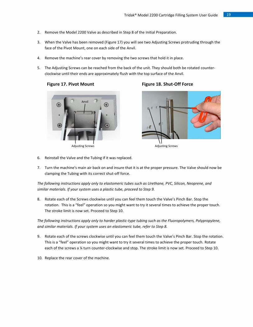
3. When the Valve has been removed (Figure 17) you will see two Adjusting Screws protruding through the
face of the Pivot Mount, one on each side of the Anvil.
4. Remove the machine’s rear cover by removing the two screws that hold it in place.
5. The Adjusting Screws can be reached from the back of the unit. They should both be rotated counter-
clockwise until their ends are approximately flush with the top surface of the Anvil.
Figure 17. Pivot Mount
Figure 18. Shut-Off Force
6. Reinstall the Valve and the Tubing if it was replaced.
7. Turn the machine's main air back on and insure that it is at the proper pressure. The Valve should now be
clamping the Tubing with its correct shut-off force.
The following instructions apply only to elastomeric tubes such as Urethane, PVC, Silicon, Neoprene, and
similar materials. If your system uses a plastic tube, proceed to Step 9.
8. Rotate each of the Screws clockwise until you can feel them touch the Valve’s Pinch Bar. Stop the
rotation. This is a “feel” operation so you might want to try it several times to achieve the proper touch.
The stroke limit is now set. Proceed to Step 10.
The following instructions apply only to harder plastic-type tubing such as the Fluoropolymers, Polypropylene,
and similar materials. If your system uses an elastomeric tube, refer to Step 8.
9. Rotate each of the screws clockwise until you can feel them touch the Valve’s Pinch Bar. Stop the rotation.
This is a “feel” operation so you might want to try it several times to achieve the proper touch. Rotate
each of the screws a ¼ turn counter-clockwise and stop. The stroke limit is now set. Proceed to Step 10.
10. Replace the rear cover of the machine.
Anvil
Adjusting Screws Adjusting Screws
20 Tridak® Model 2200 Cartridge Filling System User Guide
Cartridge Adjustments
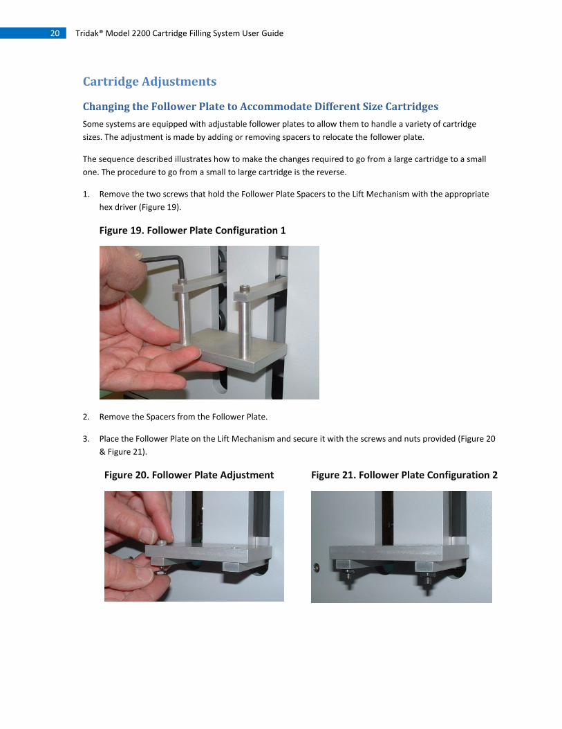
Changing the Follower Plate to Accommodate Different Size Cartridges
Some systems are equipped with adjustable follower plates to allow them to handle a variety of cartridge
sizes. The adjustment is made by adding or removing spacers to relocate the follower plate.
The sequence described illustrates how to make the changes required to go from a large cartridge to a small
one. The procedure to go from a small to large cartridge is the reverse.
1. Remove the two screws that hold the Follower Plate Spacers to the Lift Mechanism with the appropriate
hex driver (Figure 19).
Figure 19. Follower Plate Configuration 1
2. Remove the Spacers from the Follower Plate.
3. Place the Follower Plate on the Lift Mechanism and secure it with the screws and nuts provided (Figure 20
& Figure 21).
Figure 20. Follower Plate Adjustment
Figure 21. Follower Plate Configuration 2

21 Tridak® Model 2200 Cartridge Filling System User Guide
Maintenance
The Model 2200 system utilizes a disposable fluid path constructed of tubing. Fluids are carried from the
system’s material reservoir to the dispensing nozzle in a completely sealed path, insuring no contact with the
valve’s internal components. This reduces wear to the valve’s internal components, reducing valve
maintenance and extending the valve’s life. It also insures that fluids remain contaminate free throughout the
filling process.
The Model 2200 system is compatible with a variety of different tubing sizes and materials, allowing complete
compatibility with the fluids being used. The system’s disposable fluid path is easy to replace and change out,
making material changeover simple with little or no clean-up.
Troubleshooting
Problem Possible Cause Corrective Action
Nothing is dispensing
The reservoir’s air pressure is too low Increase the supply air pressure
The valve is not properly adjusted Follow the valve adjustment procedures
There are air bubbles in the fluid
The system is not properly purged Follow the procedure to prime the system
There is a problem with the material reservoir and the fluid delivery system
Diagnose and repair
Material is leaking from the dispensing nozzle
The valve is not properly adjusted Follow the valve adjustment procedures
An air bubble is trapped in the fluid body or in the dispense nozzle
Follow the procedure to prime the system
The dispense rate is too fast
The fluid pressure is set too high Decrease the fluid pressure in the reservoir
The valve is not properly adjusted Follow the valve adjustment procedures
The dispense rate is too slow
The fluid pressure is set too low Increase the fluid pressure in the reservoir
The valve is not properly adjusted Follow the valve adjustment procedures
22 Tridak® Model 2200 Cartridge Filling System User Guide
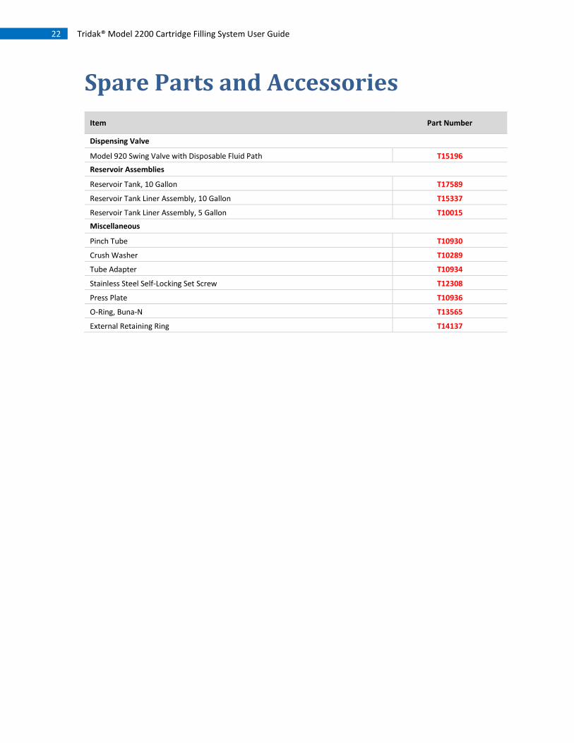
Spare Parts and Accessories
Item Part Number
Dispensing Valve
Model 920 Swing Valve with Disposable Fluid Path T15196
Reservoir Assemblies
Reservoir Tank, 10 Gallon T17589
Reservoir Tank Liner Assembly, 10 Gallon T15337
Reservoir Tank Liner Assembly, 5 Gallon T10015
Miscellaneous
Pinch Tube T10930
Crush Washer T10289
Tube Adapter T10934
Stainless Steel Self-Locking Set Screw T12308
Press Plate T10936
O-Ring, Buna-N T13565
External Retaining Ring T14137

23 Tridak® Model 2200 Cartridge Filling System User Guide
Specifications
System Specifications
Part Numbers
T10071 - Model 2200 Cartridge Filler (No Reservoir)
T17589 - 10 Gallon Drop-In Reservoir Tank
T15337 - 10 Gallon Tank Liner Assembly
T10015 - 5 Gallon Tank Liner Assembly
Materials of Construction
Dispensing Valve = Model 920 Dispensing Valve with Disposable Fluid Path
System Base = Anodized Aluminum
Wetted Parts
Fluid Tubing = Light-Blocking, Black, Polyethylene
Fluid Tubing Fittings = Acetal
Tridak Drop-In Tank Reservoirs = Stainless Steel
Tridak Drop-In Tank Liner = Polypropylene
Operating Specifications
Operating air pressure for the Model 2200 Cartridge Filler = 60-80 psi [4.1 – 5.5 bar], 50 micron filtered,
non-lubricated, dry air
Operating air pressure for the 10 Gallon Drop-In Reservoir Tank = Maximum rated pressure: 100 psi [0.69 MPa,
6.9 bar]
Maximum inlet fluid pressure = Tubing dependent; 65 psi [0.45 MPa, 4.9 bar](typical)
Note: The filtering for the air going into the tank should be appropriate for the material being handled. The user must decide the degree of filtration required. 60-80 psi (0.41-0.55 MPa), 50 micron filtered, non-lubricated, dry air is required.
System Activation = 3-way footswitch
Material Viscosity Range = 1,000 - 100,000 cP

24 Tridak® Model 2200 Cartridge Filling System User Guide
Compatible Sizes
Cartridges and syringe barrels up to 500 mL
Maximum cartridge height: 7" (18 cm)
Maximum cartridge/piston diameter: 2.5" (6.5 cm)
Dimensions
Dimensions (W x D x H) for base unit only = 16.25" x 16.25" x 27" [41.28 cm x 41.28 cm x 68.58 cm]
Figure 22. Model 2200 System Dimensions (Base Only)

25 Tridak® Model 2200 Cartridge Filling System User Guide
Warranty From date of purchase, Dymax offers a one-year warranty against defects in material and workmanship on all
system components with proof of purchase and purchase date. Unauthorized repair, modification, or
improper use of equipment may void your warranty benefits. The use of aftermarket replacement parts not
supplied or approved by Dymax, will void any effective warranties and may result in damage to the
equipment.
IMPORTANT NOTE: DYMAX RESERVES THE RIGHT TO INVALIDATE ANY WARRANTIES, EXPRESSED OR IMPLIED,
DUE TO ANY REPAIRS PERFORMED OR ATTEMPTED ON TRIDAK EQUIPMENT WITHOUT WRITTEN
AUTHORIZATION FROM DYMAX. THOSE CORRECTIVE ACTIONS LISTED ABOVE ARE LIMITED TO THIS
AUTHORIZATION.

26 Tridak® Model 2200 Cartridge Filling System User Guide
Index
Accessories, 22
Assembly, 8
Components, 7
Contact Information, 4
Description of System Components, 7
Dimensions, 23
Fill Height Adjustment, 13
Help, 4
Maintenance, 21
Operation, 16
Optional Equipment, 22
Parts Included, 9
Preparing the System for Use, 9 Filling the Plastic Reservoir, 14 Initial Preparation, 9 Installing the Nozzle, 12 Preparing the Plastic Reservoir, 11 Priming the System, 15 Setting the Fill Height, 13 Turing on the Air to the Tank, 15 Turing on the Main Air, 14
Priming the System, 15
Product Overview, 6
Removing the Tank Top, 17
Safety, 4, 5 Personal Protective Equipment, 5 Preventing Injection Injury, 5 Using Safe Operating Pressures, 5
Setup, 8
Spare Parts, 22
Specifications, 23 Materials of Construction, 23 Operating Specifications, 23 Part Numbers, 23
Support, 4
System Adjustments, 17 Adjusting the System for Different Size Cartridges, 20
Adjusting the Valve Stroke, 17 Adjusting the Valve Stroke Limit, 18
System Benefits, 6
System Features, 6
Troubleshooting, 21
Unpacking, 8
Warranty, 25

27 Tridak® Model 2200 Cartridge Filling System User Guide

© 2013-2016 Dymax Corporation. All rights reserved. All trademarks in this guide, except where noted, are the property of, or used under license by Dymax Corporation, U.S.A.
Please note that most filling and repackaging system applications are unique. Dymax does not warrant the fitness of the product for the intended application. Any warranty applicable to the product, its application and use is strictly limited to that contained in Dymax’s standard Conditions of Sale. Dymax recommends that any intended application be evaluated and tested by the user to insure that desired performance criteria are satisfied. Dymax is willing to assist users in their performance testing and evaluation. Data sheets are available for pressure pots upon request. T17593 MAN049 1/20/2015
Dymax Corporation +1.860.482.1010 | [email protected] | www.dymax.com
Dymax Oligomers & Coatings +1.860.626.7006 | [email protected] | www.dymax-oc.com
Dymax Asia (H.K.) Limited +852.2460.7038 | [email protected] | www.dymax.com.cn
Dymax Europe GmbH +49 611.962.7900 | [email protected] | www.dymax.de
Dymax UV Adhesives & Equipment (Shanghai) Co. Ltd. +86.21.37285759 | [email protected] | www.dymax.com.cn
Dymax Asia Pacific Pte. Ltd. +65.6752.2887 | [email protected] | www.dymax-ap.com
Dymax Engineering Adhesives Ireland Ltd. +353 21.237.3016 | [email protected] | www.dymax.ie
Dymax UV Adhesives & Equipment (Shenzhen) Co. Ltd. +86.755.83485759 | [email protected] | www.dymax.com.cn
Dymax Korea LLC +82.2.784.3434 | [email protected] | www.dymax.com/kr


