16
TriFlex ™ Powered Subwoofer and Stereo Satellite System For more information on other great Peavey products, visit your local Peavey dealer or go online to www.peavey.com
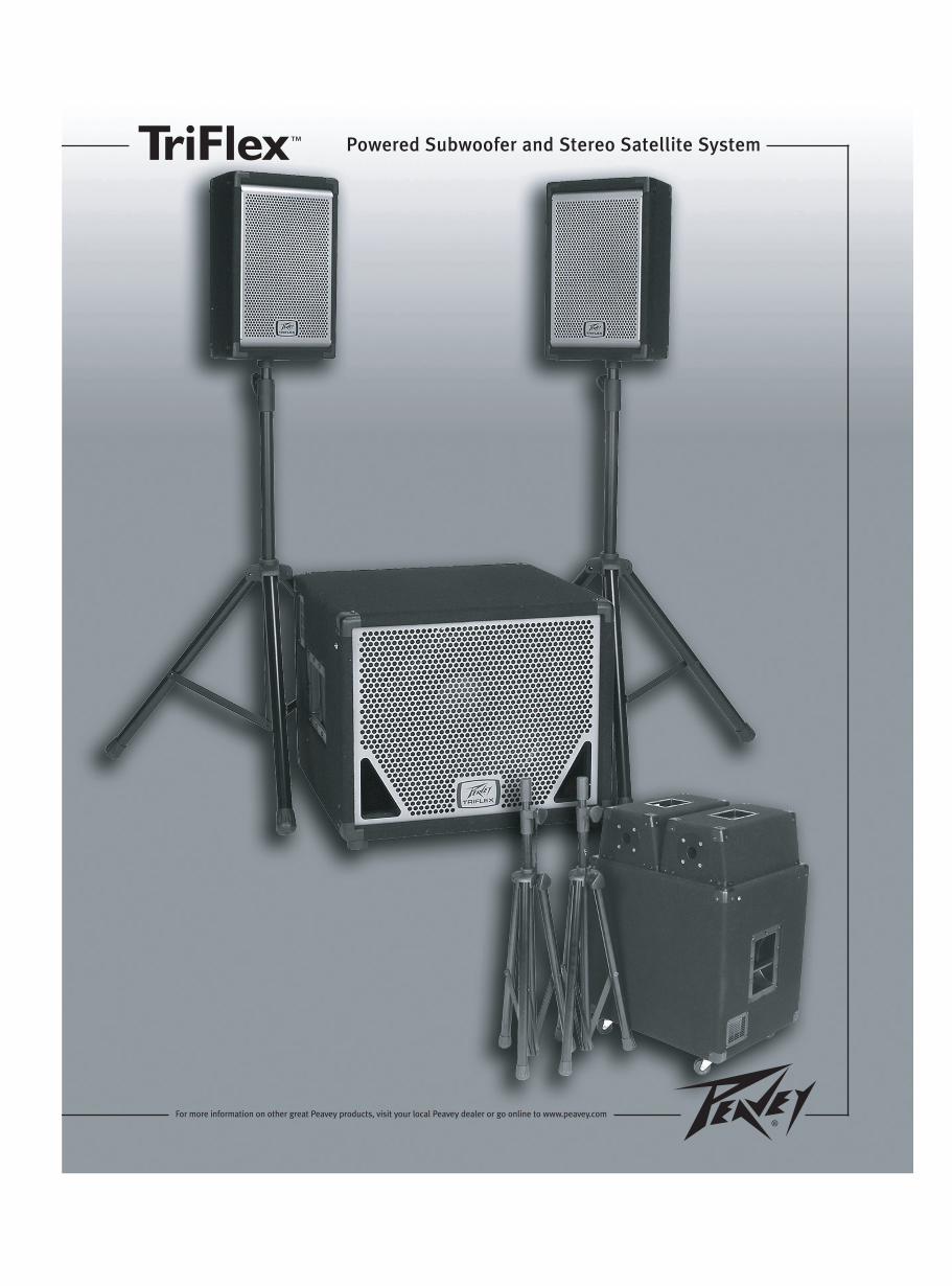
TriFlex™ Powered Subwoofer and Stereo Satellite System
For more information on other great Peavey products, visit your local Peavey dealer or go online to www.peavey.com
2
Intended to alert the user to the presence of uninsulated “dangerous voltage” within the product’senclosure that may be of sufficient magnitude to constitute a risk of electric shock to persons.
Intended to alert the user of the presence of important operating and maintenance (servicing)instructions in the literature accompanying the product.
CCAAUUTTIIOONN:: Risk of electrical shock — DO NOT OPEN!CCAAUUTTIIOONN:: To reduce the risk of electric shock, do not remove cover. No user serviceable parts inside.Refer servicing to qualified service personnel.
WWAARRNNIINNGG:: To prevent electrical shock or fire hazard, do not expose this appliance to rain or moisture.Before using this appliance, read the operating guide for further warnings.
Este símbolo tiene el propósito, de alertar al usuario de la presencia de “(voltaje) peligroso” sinaislamiento dentro de la caja del producto y que puede tener una magnitud suficiente como paraconstituir riesgo de descarga eléctrica.
Este símbolo tiene el propósito de alertar al usario de la presencia de instruccones importantes sobre laoperación y mantenimiento en la información que viene con el producto.
PPRREECCAAUUCCIIOONN:: Riesgo de descarga eléctrica ¡NO ABRIR!PPRREECCAAUUCCIIOONN:: Para disminuír el riesgo de descarga eléctrica, no abra la cubierta. No hay piezas útilesdentro. Deje todo mantenimiento en manos del personal técnico cualificado.
AADDVVEERRTTEENNCCIIAA:: Para evitar descargas eléctricas o peligro de incendio, no deje expuesto a la lluvia ohumedad este aparato Antes de usar este aparato, Iea más advertencias en la guía de operación.
Ce symbole est utilisé dans ce manuel pour indiquer à l’utilisateur la présence d’une tension dangereusepouvant être d’amplitude suffisante pour constituer un risque de choc électrique.
Ce symbole est utilisé dans ce manuel pour indiquer à l’utilisateur qu’il ou qu’elle trouvera d’importantesinstructions concernant l’utilisation et l’entretien de l’appareil dans le paragraphe signalé.
AATTTTEENNTTIIOONN:: Risques de choc électrique — NE PAS OUVRIR!AATTTTEENNTTIIOONN:: Afin de réduire le risque de choc électrique, ne pas enlever le couvercle. Il ne se trouve àl’intérieur aucune pièce pouvant être reparée par l’utilisateur. Confiez I’entretien et la réparation del’appareil à un réparateur Peavey agréé.
AAVVEERRTTIISSSSEEMMEENNTT: Afin de prévenir les risques de décharge électrique ou de feu, n’exposez pas cetappareil à la pluie ou à l’humidité. Avant d’utiliser cet appareil, lisez attentivement les avertissementssupplémentaires de ce manuel.
Dieses Symbol soll den Anwender vor unisolierten gefährlichen Spannungen innerhalb des Gehäuseswarnen, die von Ausreichender Stärke sind, um einen elektrischen Schlag verursachen zu können.
Dieses Symbol soll den Benutzer auf wichtige Instruktionen in der Bedienungsanleitung aufmerksammachen, die Handhabung und Wartung des Produkts betreffen.
VVOORRSSIICCHHTT:: Risiko — Elektrischer Schlag! Nicht öffnen!VVOORRSSIICCHHTT:: Um das Risiko eines elektrischen Schlages zu vermeiden, nicht die Abdeckung enfernen. Esbefinden sich keine Teile darin, die vom Anwender repariert werden könnten. Reparaturen nur vonqualifiziertem Fachpersonal durchführen lassen.
AACCHHTTUUNNGG:: Um einen elektrischen Schlag oder Feuergefahr zu vermeiden, sollte dieses Gerät nicht demRegen oder Feuchtigkeit ausgesetzt werden. Vor Inbetriebnahme unbedingt die Bedienungsanleitung lesen.
3
IIMMPPOORRTTAANNTT SSAAFFEETTYY IINNSSTTRRUUCCTTIIOONNSS
WWAARRNNIINNGG:: When using electrical products, basic cautions should always be followed, including the following:
1. Read these instructions.
2. Keep these instructions.
3. Heed all warnings.
4. Follow all instructions.
5. Do not use this apparatus near water.
6. Clean only with a dry cloth.
7. Do not block any of the ventilation openings. Install in accordance with manufacturer’s instructions.
8. Do not install near any heat sources such as radiators, heat registers, stoves or other apparatus (includingamplifiers) that produce heat.
9. Do not defeat the safety purpose of the polarized or grounding-type plug. A polarized plug has two blades with onewider than the other. A grounding type plug has two blades and a third grounding plug. The wide blade or thirdprong is provided for your safety. If the provided plug does not fit into your outlet, consult an electrician forreplacement of the obsolete outlet.
10. Protect the power cord from being walked on or pinched, particularly at plugs, convenience receptacles, and thepoint they exit from the apparatus.
11. Note for UK only: If the colors of the wires in the mains lead of this unit do not correspond with the terminals in yourplug‚ proceed as follows:
a) The wire that is colored green and yellow must be connected to the terminal that is marked by the letter E‚ theearth symbol‚ colored green or colored green and yellow.
b) The wire that is colored blue must be connected to the terminal that is marked with the letter N or the color black.
c) The wire that is colored brown must be connected to the terminal that is marked with the letter L or the color red.
12. Only use attachments/accessories provided by the manufacturer.
13. Use only with a cart, stand, tripod, bracket, or table specified by the manufacturer, or sold with the apparatus. Whena cart is used, use caution when moving the cart/apparatus combination to avoid injury from tip-over.
14. Unplug this apparatus during lightning storms or when unused for long periods of time.
15. Refer all servicing to qualified service personnel. Servicing is required when the apparatus has been damaged inany way, such as power-supply cord or plug is damaged, liquid has been spilled or objects have fallen into theapparatus, the apparatus has been exposed to rain or moisture, does not operate normally, or has been dropped.
16. Never break off the ground pin. Write for our free booklet “Shock Hazard and Grounding.” Connect only to a powersupply of the type marked on the unit adjacent to the power supply cord.
17. If this product is to be mounted in an equipment rack, rear support should be provided.
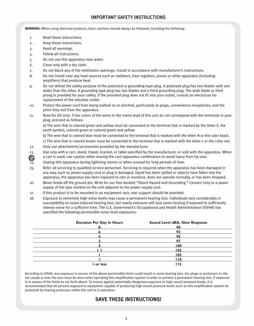
18. Exposure to extremely high noise levels may cause a permanent hearing loss. Individuals vary considerably insusceptibility to noise-induced hearing loss, but nearly everyone will lose some hearing if exposed to sufficientlyintense noise for a sufficient time. The U.S. Government’s Occupational and Health Administration (OSHA) hasspecified the following permissible noise level exposures:
Duration Per Day In Hours Sound Level dBA, Slow Response8 906 924 953 972 100
1 1⁄2 1021 1051⁄2 110
1⁄4 or less 115
According to OSHA, any exposure in excess of the above permissible limits could result in some hearing loss. Ear plugs or protectors to theear canals or over the ears must be worn when operating this amplification system in order to prevent a permanent hearing loss, if exposureis in excess of the limits as set forth above. To ensure against potentially dangerous exposure to high sound pressure levels, it isrecommended that all persons exposed to equipment capable of producing high sound pressure levels such as this amplification system beprotected by hearing protectors while this unit is in operation.
SSAAVVEE TTHHEESSEE IINNSSTTRRUUCCTTIIOONNSS!!
4
TriFlex™Powered Subwoofer and Stereo Satellite System
Thank you for purchasing the TriFlex. The TriFlex is designed‚ from start to finish‚ with flexibility in mind. This system delivers 1500Watts of peak dynamic power to the sub and another 750 Watts of peak dynamic power to the left and right satellite speakeroutputs. The TriFlex is designed as a complete package, with a subwoofer driving its own pair of satellite mid/high frequency passivespeakers from the left and right power output jacks. There also are facilities for line-level mid/high outputs for driving othermid/high frequency active, separately powered speakers. Alternatively, the TriFlex powered subwoofer can be used as a stand-alonesub.
Featuring Peavey’s patented DDT™ compression‚ the awarding-winning KOSMOS® and a Low Rider® Black Widow® woofer, theTriFlex is one of the most portable, powerful, and flexible 3-way systems available.
Please read this guide carefully to ensure your personal safety as well as the safety of your equipment.
Features
➡ Powered system with 1000 Watts of continuous power and 1500 Watts of peak dynamic power
➡ DDT compression (amplifier protection and clip eliminator)
➡ 15" Low Rider bass woofer
➡ Peak SPL in excess of 128 dB
➡ KOSMOS sub-harmonic generator system with bypass switch
➡ Left & right power amp outputs with high-pass crossover for the satellites
➡ Built-in electronic crossover with line-level high-pass output
➡ 1/4" TRS and female XLR line-level balanced inputs
➡ Male XLR thru output
➡ Compact dimensions
➡ Heavy duty‚ inset handles on both sides
➡ Lockable casters
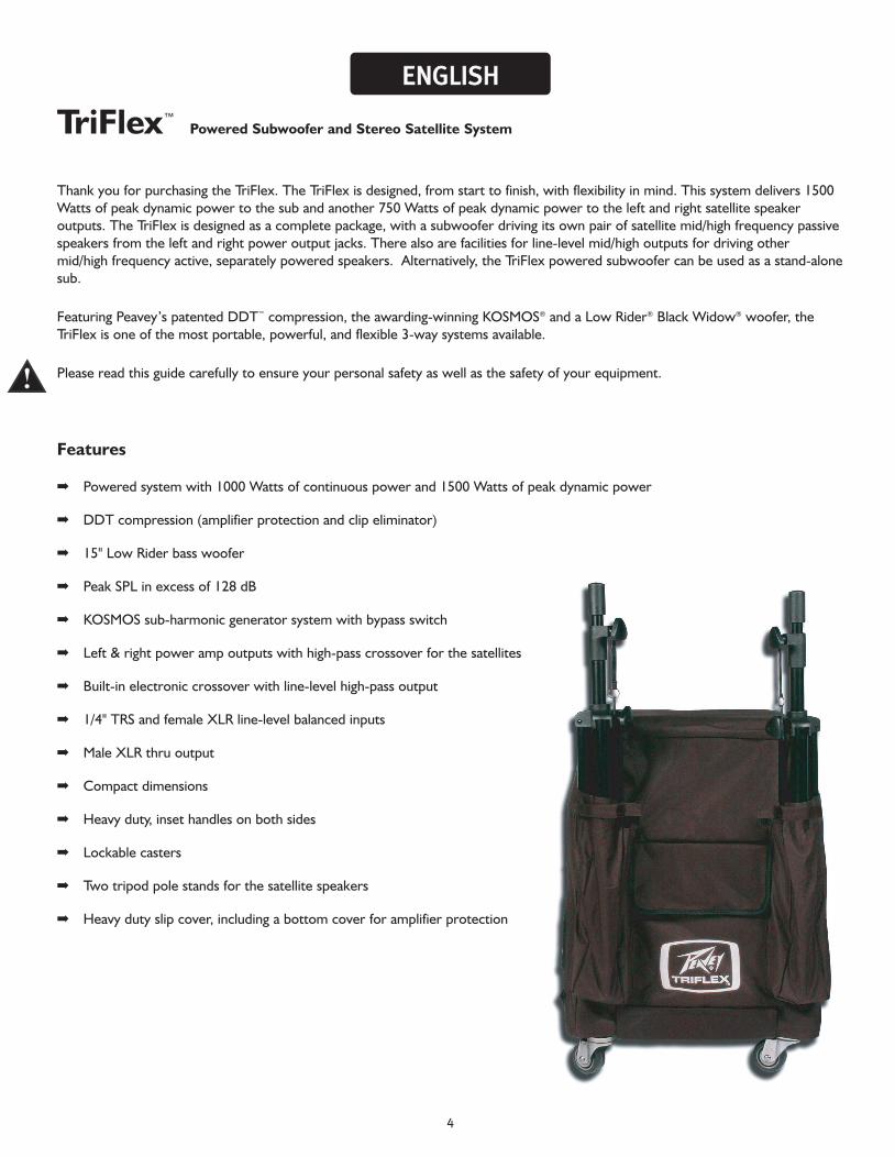
➡ Two tripod pole stands for the satellite speakers
➡ Heavy duty slip cover, including a bottom cover for amplifier protection
EENNGGLLIISSHH
C
M
Y
CM
MY
CY
CMY
K
Page 4.pdf 8/30/04 6:55:03 PMPage 4.pdf 8/30/04 6:55:03 PM
5
Description
The Peavey® TriFlex™ is a powered‚ three-way piece speaker system designed to provide the highest levels ofperformance in a compact package. The subwoofer unit is loaded with the new‚ high power handling 15" Low Rider®
Black Widow® bass woofer. The TriFlex subwoofer is constructed of premium plywood‚ covered with a tough‚ road-worthy black carpet. A 16-gauge, perforated metal grille with powder-coated finish covers the front of the system toprotect the speakers. The TriFlex includes two tripod pole stands for mounting the speakers.
Flexibility is designed into the TriFlex. Balanced inputs for each channel are provided and include one combo femaleXLR and 1/4" TRS phone jack plus one male XLR thru, all connected in parallel. The power amplifiers are low-distortion units that supply 1500 Watts of peak dynamic power to the bridged subwoofer, and up to 750 Watts peakdynamic power to the left and right satellite speakers. The amplifiers feature Peavey’s patented DDT™ compressionthat virtually eliminates audible power amplifier clipping.
For ease of transport, inset metal handles on each side of the sub are provided. For pack-up and transport, removablelocking casters are located on the rear of the sub. This allows the unit to be rotated onto its back and moved withease. In this position, the satellites are designed to rest face-to-face on the sub's grille. The entire unit is slipcovered,with a protective flap for the amplifier, which becomes the bottom of the unit when rolled. The speaker cables areplaced in the cover pockets and the speaker stands in their own pouches. This makes for a compact and completepackage for easy transport.
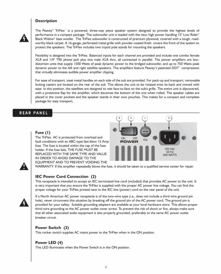
Fuse (1)The TriFlex AC is protected from overload andfault conditions with an ABC-type fast-blow 15 Ampfuse. The fuse is located within the cap of the fuseholder. If the fuse fails, THE FUSE MUST BEREPLACED WITH THE SAME TYPE AND VALUEIN ORDER TO AVOID DAMAGE TO THEEQUIPMENT AND TO PREVENT VOIDING THEWARRANTY. If the amplifier repeatedly blows the fuse, it should be taken to a qualified service center for repair.
IEC Power Cord Connection (2)This receptacle is intended to accept an IEC terminated line cord (included) that provides AC power to the unit. Itis very important that you ensure the TriFlex is supplied with the proper AC power line voltage. You can find theproper voltage for your TriFlex printed next to the IEC line (power) cord on the rear panel of the unit.
If a North American AC power receptacle is of the two-wire type (i.e., does not include a third wire ground pinhole), never circumvent this situation by breaking off the ground pin of the AC power cord. The ground pin isprovided for your safety. Suitable grounding adapters are available at your local hardware store. This allows properthird-wire grounding to the AC power outlet cover screw. To prevent the risk of shock or fire, always make surethat all other associated audio equipment is also properly grounded, preferably to the same AC power outletbreaker circuit.
Power Switch (3)This rocker switch supplies AC mains power to the TriFlex when in the ON position.
Power LED (4)This LED illuminates when the Power Switch is in the ON position.
RR EE AA RR PP AA NN EE LL
ON OFFPOWER 15A
60 Hz120 VAC
600 WATTS
F
F
U
U
S
S
E
E
134 2
6
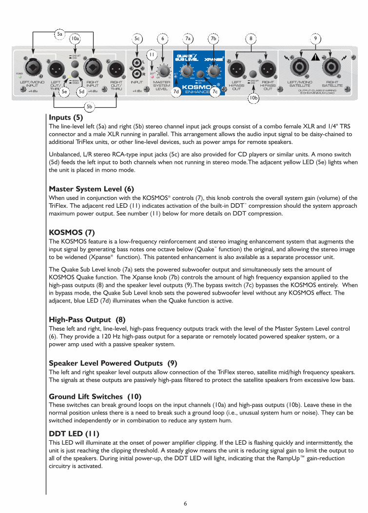
Inputs (5)The line-level left (5a) and right (5b) stereo channel input jack groups consist of a combo female XLR and 1/4" TRSconnector and a male XLR running in parallel. This arrangement allows the audio input signal to be daisy-chained toadditional TriFlex units, or other line-level devices, such as power amps for remote speakers.
Unbalanced‚ L/R stereo RCA-type input jacks (5c) are also provided for CD players or similar units. A mono switch(5d) feeds the left input to both channels when not running in stereo mode.The adjacent yellow LED (5e) lights whenthe unit is placed in mono mode.
Master System Level (6)When used in conjunction with the KOSMOS® controls (7)‚ this knob controls the overall system gain (volume) of theTriFlex. The adjacent red LED (11) indicates activation of the built-in DDT™ compression should the system approachmaximum power output. See number (11) below for more details on DDT compression.
KOSMOS (7)The KOSMOS feature is a low-frequency reinforcement and stereo imaging enhancement system that augments theinput signal by generating bass notes one octave below (Quake™ function) the original, and allowing the stereo imageto be widened (Xpanse® function). This patented enhancement is also available as a separate processor unit.
The Quake Sub Level knob (7a) sets the powered subwoofer output and simultaneously sets the amount ofKOSMOS Quake function. The Xpanse knob (7b) controls the amount of high frequency expansion applied to thehigh-pass outputs (8) and the speaker level outputs (9).The bypass switch (7c) bypasses the KOSMOS entirely. Whenin bypass mode‚ the Quake Sub Level knob sets the powered subwoofer level without any KOSMOS effect. Theadjacent‚ blue LED (7d) illuminates when the Quake function is active.
High-Pass Output (8)These left and right‚ line-level‚ high-pass frequency outputs track with the level of the Master System Level control(6). They provide a 120 Hz high-pass output for a separate or remotely located powered speaker system, or apower amp used with a passive speaker system.
Speaker Level Powered Outputs (9)The left and right speaker level outputs allow connection of the TriFlex stereo, satellite mid/high frequency speakers.The signals at these outputs are passively high-pass filtered to protect the satellite speakers from excessive low bass.
Ground Lift Switches (10)These switches can break ground loops on the input channels (10a) and high-pass outputs (10b). Leave these in thenormal position unless there is a need to break such a ground loop (i.e., unusual system hum or noise). They can beswitched independently or in combination to reduce any system hum.
DDT LED (11)This LED will illuminate at the onset of power amplifier clipping. If the LED is flashing quickly and intermittently‚ theunit is just reaching the clipping threshold. A steady glow means the unit is reducing signal gain to limit the output toall of the speakers. During initial power-up‚ the DDT LED will light‚ indicating that the RampUp™ gain-reductioncircuitry is activated.
LEFT/MONOINPUT
LEFTOUT/THRU
RIGHTINPUT
RIGHTOUT/THRU
INPUT MASTERSYSTEM
LEVEL
LEFTHI PASS
OUT
RIGHTHI PASS
OUT
LEFT/MONOSATELLITE
RIGHTSATELLITE
L
ROFF MAX MIN MAXOFF 10
ACTPOWER
OUTPUT-CLASS 2 WIRING8 OHM MINIMUM LOAD
MONOSTEREO
GND LIFTGND
DDT
GND LIFTGND
+4 dBu +4 dBu +4 dBu
BYPASSON
TM
ENHANCEDKOSMOS
QUAKE /QUAKE /SUB LEVELSUB LEVEL
TM
XPANSEXPANSE
5c
5d5e 7c
8 9
10b
11
5a10a
5b
7a 7b6
7d
Using the Pole Stand Base The included tripod pole stand allows the use of the TriFlex satellite speakers. These pole stands should not beextended beyond 65" in height or carry more than 20 lbs. each in weight.
Sending Audio Signal to the TriFlexThere are a variety of ways to provide audio signals to the TriFlex. The balanced line-level input(s) allow theuse of an XLR plug or a 1/4" phone plug: either a standard, single-ended TS (tip/sleeve) plug or a balanced TRS(tip/ring/sleeve) type 1/4" phone plug. It is not advisable to connect cables to the jacks while the unit is ON andthe volume is turned up.
The XLR plug will provide superior performance, whereas the standard‚ single-ended 1/4" phone plug will alsowork and the balanced input circuitry will provide some interference rejection. Plugging into the RCA jacks orplugging a mono 1/4" plug into the combo jack will cause the thru jack to operate in unbalanced mode. If humor other interference problems result from the thru output‚ it will be helpful to lift the ground TriFlex inputonly. This can be accomplished via the convenient ground lift switch (10a) found underneath the input jackgroup. Check any input changes carefully. Always turn the volume controls down before plugging andunplugging cables or switching the ground lift switches.
Volume Control Adjustment The TriFlex is equipped with a Master System Level volume control (6). When the Master System Level isadjusted fully clockwise‚ gain is at maximum and the input sensitivity is 0.375 VRMS for full-rated output. Whenthis control is set halfway up‚ gain is unity and 1.5 VRMS will drive the system to full power output. Whendriving the TriFlex from a mixer‚ it may be advantageous to reduce the input sensitivity by turning the volumecontrol to the halfway point. At this setting‚ the TriFlex will more closely match the output of a mixer andprovide an appropriate input of the internal power amp.
The amplifiers in the TriFlex are equipped with DDT™ compression. This unit also includes an LED (11) thatilluminates when DDT is activated. This LED is located next to the Master System level. The DDT circuit willautomatically reduce the system gain to a level just slightly into clipping, guarding the speakers against theoverloads. Situations that may activate the DDT circuit include uncontrolled feedback, oscillations, or animproper equipment setting or malfunction upstream from the TriFlex system.
Always turn any peripheral units to ON before turning on the TriFlex. Also‚ make sure the Master SystemLevelis completely down (counterclockwise) before turning the unit on. Likewise, turn the TriFlex system to OFFbefore shutting down any peripheral units.
OPERATING INSTRUCTIONS
CAUTIONS
Clearance of 12" or 10 cm from the rear of the sub to any combustible surface must be maintained.
The left input jack group or right input jack group (5) are hard-wired together to allow use of anyof the connector types as an input and to allow a further send or daisy-chaining of the input signalto some other audio device (such as another TrifFex™). Attempting to run two individual signals intothe TriFlex left input jack group or right input group could damage the output(s) of the sourceunit(s). Use a mixer to combine two or more signals into a single channel before sending to theTriFlex input.
Warning: The TriFlex sound system can permanently damage hearing. Use caution when setting theoverall maximum loudness.This system is capable of SPL in excess of 128 dB at 1m from the speaker!
7
Adjusting the KOSMOS® Processing LevelThe amount of KOSMOS processing is dependent upon the input signal level of the TriFlex™ system. In order toachieve more subharmonic processing‚ turn the Quake™ Sub Level knob (7a) up. Similarly, the amount of stereospread is controlled by the Xpanse® level knob (7b).
When using the TriFlex with a powered‚ full-range speaker system from the line-level‚ high-pass outputs (8)‚ thepowered‚ full-range speakers will usually have their own volume control. This will allow the high frequency level tobe set independently. However‚ the KOSMOS Xpanse control (7b) for adjusting stereo spread can only be adjustedat the TriFlex subwoofer.
High-Pass Outputs These are low impedance‚ high-pass frequency outputs that are provided to send the high frequencies to apowered speaker or to a conventional power amp and a separate speaker system than the TriFlex satellitespeakers. The output level tracks the Master System level control on the TriFlex.
The nominal polarity of these outputs is positive (pin 2) and can be run directly into most full-range‚ poweredspeaker systems, or to a conventional power amp and a separate speaker system. If you experience hum or relatedground loop problems‚ it might help to lift the shield ground on the balanced XLR cable at the TriFlex end. This canbe accomplished via the convenient ground lift switch (10b) located underneath the High-pass output jack group.Check any input changes carefully. Always turn the volume control down before plugging and unplugging cables orswitching ground lift switches.
Left & Right Outputs These outputs will supply a full-range‚ 8 Ohm minimum speaker system with a high-pass frequency amplifier signalwhen using the TriFlex with speakers other than the TriFlex satellite speakers. The Xpanse control (7b) will expandthe stereo sound stage and add high frequency processing to these outputs.
TriFlex as a Subwoofer Only (Add-On Use) When using the TriFlex as a powered subwoofer only‚ connect a full-range stereo signal to the inputs (5) or plug amono signal into the left input (5a) and engage the Mono switch (5d). The subwoofer will reproduce frequenciesfrom approximately 45 Hz to120 Hz.
TriFlex: Subwoofer with Built-in Crossover To fully utilize the built-in crossover‚ a line-level‚ high-pass signal is available at the high-pass output jacks (8). Usethe left output to send the high-pass output to a powered‚ full-range speaker or to a power amp and full-rangespeaker. The full-range speakers will reproduce frequencies from 120 Hz and up. This can be repeated if multipleTriFlex units are used in a larger interconnected system.
Connecting Multiple Triflex Systems The TriFlex is designed with multiple parallel inputs that allow daisy-chaining from one TriFlex system to another.Connect the first cable from the mixer output to the first TriFlex. Then‚ connect a cable from the first TriFlex's thrujack to the second TriFlex’s input. This connection can be continued for several units‚ depending on the total lengthand capacitance of the cables. With a low source impedance output from a typical mixer and by using quality‚balanced cables‚ several TriFlex systems can be daisy-chained from one output using 30 or 40 foot cables withoutobvious problems or distortion. It is not advisable to connect cables to the jacks while the units are ON and theVolume is turned up.
8
9
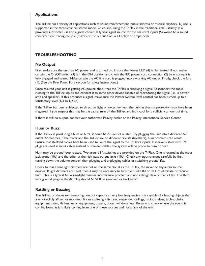
Applications
The TriFlex has a variety of applications such as sound reinforcement‚ public address or musical playback. DJ use issupported in the three-channel stereo mode. Of course‚ using the TriFlex in the traditional role - strictly as apowered subwoofer - is also a great choice. A typical signal source for the line-level inputs (5) would be a soundreinforcement mixing console (mixer) or the output from a CD player or tape deck.
TROUBLESHOOTING
No Output First‚ make sure the unit has AC power and is turned on. Ensure the Power LED (4) is illuminated. If not‚ makecertain the On/Off switch (3) is in the ON position and check the IEC power cord connection (2) by ensuring it isfully engaged and seated. Make certain the AC line cord is plugged into a working AC outlet. Finally‚ check the fuse(1). (See the Rear Panel: Fuse section for safety instructions.)
Once assured your unit is getting AC power‚ check that the TriFlex is receiving a signal. Disconnect the cablerunning to the TriFlex inputs and connect it to some other device capable of reproducing the signal (i.e., a poweramp and speaker). If this produces a signal‚ make sure the Master System level control has been turned up to asatisfactory level (1/3 to 1/2 up).
If the TriFlex has been subjected to direct sunlight or excessive heat, the built-in thermal protection may have beentriggered. If you suspect this may be the cause‚ turn off the TriFlex and let it cool for a sufficient amount of time.
If there is still no output‚ contact your authorized Peavey dealer or the Peavey International Service Center.
Hum or Buzz If the TriFlex is producing a hum or buzz‚ it could be AC-outlet related. Try plugging the unit into a different ACoutlet. Sometimes‚ if the mixer and the TriFlex are on different circuits (breakers)‚ hum problems can result.Ensure that shielded cables have been used to route the signal to the TriFlex’s inputs. If speaker cables with 1/4"plugs are used as input cables instead of shielded cables‚ the system will be prone to hum or buzz.
Hum may be ground-loop related. Two ground lift switches are provided on the TriFlex. One is located at the inputjack group (10a) and the other at the high-pass output jacks (10b). Check any input changes carefully by firstturning down the volume control, then plugging and unplugging cables or switching ground lifts.
Check to make sure light dimmers are not on the same circuit as the TriFlex‚ the mixer or any audio sourcedevices. If light dimmers are used‚ then it may be necessary to turn them full ON or OFF to eliminate or reducehum. This is a typical AC wiring/light dimmer interference problem and not a design flaw of the TriFlex. The thirdwire ground plug on the AC plug should NEVER be removed or broken off.
Rattling or Buzzing The TriFlex produces extremely high output capacity at very low frequencies. It is capable of vibrating objects thatare not solidly affixed or mounted. It can excite light fixtures‚ suspended ceilings‚ racks‚ shelves‚ tables‚ chairs‚equipment cases‚ lift handles on equipment‚ casters‚ doors‚ windows‚ etc. Be sure to check where the sound iscoming from, as it is likely coming from one of these sources and not a fault of the unit.
10
Excessive High Frequency Output from the Subwoofer Ensure the Mono button (5d) is switched to the ON (In) position. This should eliminate any high frequency outputfrom the subwoofer. If the unit is being used in three-channel stereo mode‚ some high frequencies may begenerated by the subwoofer when a high-frequency signal is present in only one channel. This is normal and shouldnot present a problem.
Male Vocals Sound Muddy or BoomyThe level of the subwoofer may be turned up too high or the KOSMOS® may be set too high. Turn down thesubwoofer level by turning down the Quake™ Sub level control (7a) until the sound improves. To reduce theamount of KOSMOS processing without changing the subwoofer level‚ turn the Master System level control (6)down and the Quake Sub level control (7a) up until the subwoofer is back at the previous level. When in three-channel operation‚ turn the Quake Sub level control (7a) down.
Distorted or Fuzzy SoundFirst‚ ensure the mixer (signal source) is not clipping or being overdriven. Make sure the volume control (6) on theTriFlex™ has not been set too low. Remember‚ it takes a lot of signal to drive the unit to full power.
Check that the input plugs are fully seated in the input jacks (5) on the rear panel of the TriFlex. Ensure that theproper inputs are being used for the line-level signals and that a power amp has NOT been plugged into one of theinput jacks of the TriFlex. If an extension cord is being used to supply AC power to the unit‚ ensure that it is ofsufficient current capacity and that it is not also being used to supply power to any other device.
The TriFlex has built-in EQ to extend and smooth the natural response of the woofer in any system. Bass boost isapplied and the system has a nominally flat response and should require little‚ if any‚ additional EQ. If excessive bassboost has been added externally to the TriFlex‚ it could cause premature overload at very high SPLs. Reducing theamount of external (mixer or rack) EQ should eliminate any distortion. If the KOSMOS function switch (7c) hasbeen engaged‚ try bypassing it to see if that eliminates the distortion.
If you are using additional speakers connected to the Left and Right outputs (9)‚ ensure they 8 Ohm minimumimpedance. Remove the speakers temporarily to determine if this is the source of distortion. If the distortion isemanating from the left and right speakers‚ the total capacity of the TriFlex or the speakers has possibly beenexceeded. Reduce the drive level and re-check the speakers for impedance (8 Ohm minimum).
CARE & MAINTENANCE
Your TriFlex is a sturdy and durable product that will provide years of reliable use if properly cared for. Usecommon sense and read the safety warnings to avoid hazardous operating conditions. The unit must bedisconnected from the AC power source before any maintenance is performed. Please refer all service issues toqualified service personnel.
Sunlight/Heat Avoid prolonged exposure to direct sunlight, as this may cause the unit to overheat and shut down. Excessively hotoperating conditions can also cause a thermal shutdown. Do not store in extremely hot or cold conditions orextremely high humidity.
Cleaning A dry cloth may be used to remove soil or other dirt. Never use strong solvents on the TriFlex. Do not allow anyfluids to drip inside the TriFlex system's vent openings, or through the grille.
Check for Secure Hardware After the first few months of use and periodically thereafter‚ check the hardware for tightness. Make sure to checkthe rear-panel screws and the baffle screws. The unit‚ in use‚ is subject to a great deal of vibration that may causethe screws to loosen over time.
11
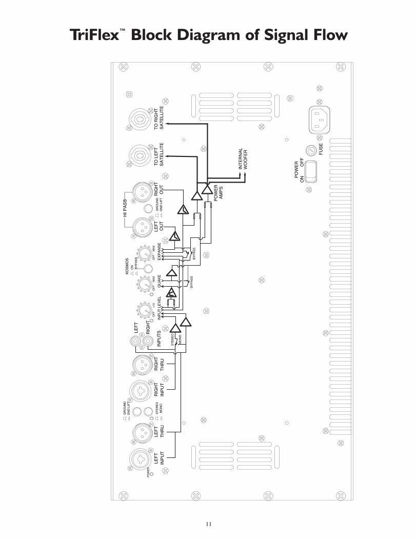
TriFlex™ Block Diagram of Signal Flow
POW
ER
FUSE
OFF
ON
OFF
+10
MAX
OFF
MAX
OFF
QU
AKE
INPU
T LE
VEL
INPU
TSLEFT
RIG
HT
LEFT
LEFT
RIG
HT
RIG
HT
LEFT
OU
TR
IGH
TO
UT
TO L
EFT
SATE
LLIT
ETO
RIG
HT
SATE
LLIT
EIN
PUT
THR
UIN
PUT
THR
U
POW
ER
EXPA
NSE
GR
OU
ND
GN
D L
IFT
STER
EOM
ON
O
ON BY
PASS
KOSM
OS
GN
D L
IFT
GR
OU
ND
HI P
ASS
BYPA
SSBY
PASS
STER
EO
MO
NO
POW
ER
AM
PS
INTE
RN
AL
WO
OFE
R
12
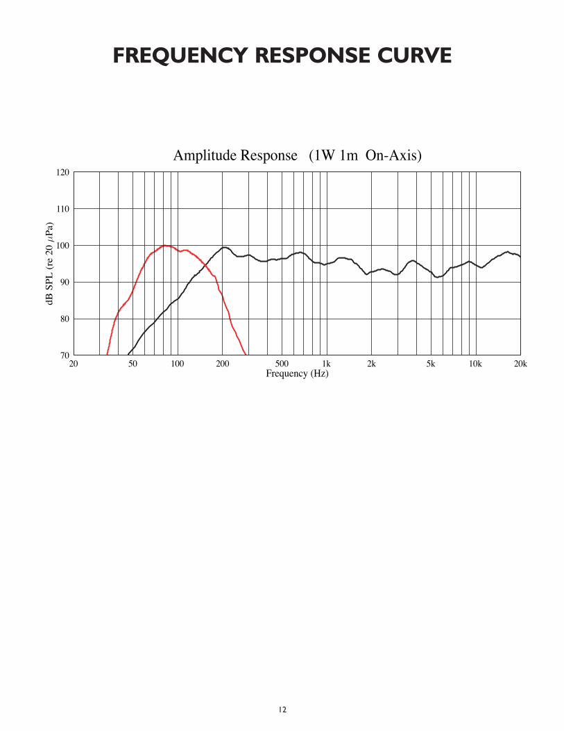
FREQUENCY RESPONSE CURVE
20 50 100 200 500 1k 2k 5k 10k 20kFrequency (Hz)
70
80
90
100
110
120
dBSPL(re20
Pa)
Amplitude Response (1W 1m On-Axis)
13
TTrriiFFlleexx™
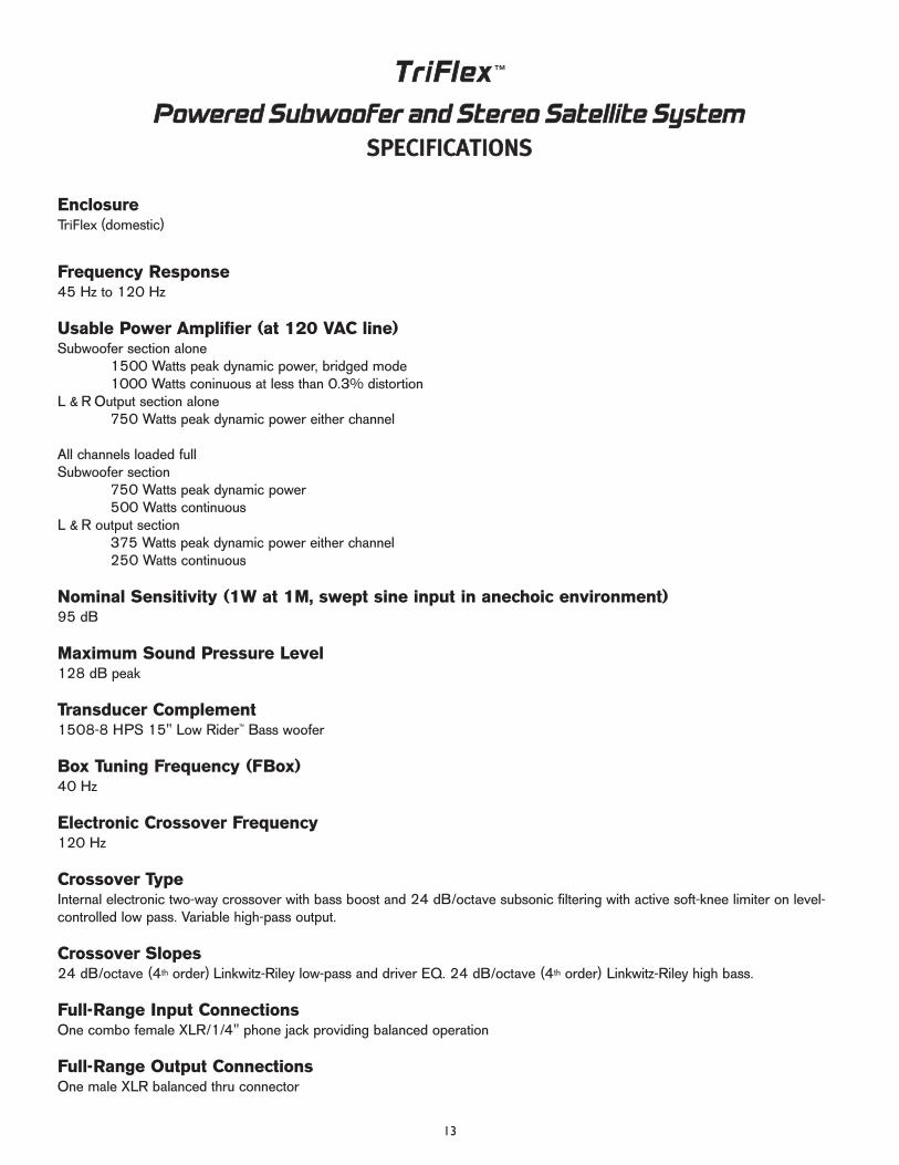
PPoowweerreedd SSuubbwwooooffeerr aanndd SStteerreeoo SSaatteelllliittee SSyysstteemmSSPPEECCIIFFIICCAATTIIOONNSS
EnclosureTriFlex (domestic)
Frequency Response45 Hz to 120 Hz
Usable Power Amplifier (at 120 VAC line)Subwoofer section alone
1500 Watts peak dynamic power, bridged mode1000 Watts coninuous at less than 0.3% distortion
L & R Output section alone750 Watts peak dynamic power either channel
All channels loaded fullSubwoofer section
750 Watts peak dynamic power500 Watts continuous
L & R output section375 Watts peak dynamic power either channel250 Watts continuous
Nominal Sensitivity (1W at 1M, swept sine input in anechoic environment)95 dB
Maximum Sound Pressure Level128 dB peak
Transducer Complement1508-8 HPS 15" Low Rider™ Bass woofer
Box Tuning Frequency (FBox)40 Hz
Electronic Crossover Frequency120 Hz
Crossover TypeInternal electronic two-way crossover with bass boost and 24 dB/octave subsonic filtering with active soft-knee limiter on level-controlled low pass. Variable high-pass output.
Crossover Slopes24 dB/octave (4th order) Linkwitz-Riley low-pass and driver EQ. 24 dB/octave (4th order) Linkwitz-Riley high bass.
Full-Range Input ConnectionsOne combo female XLR/1/4" phone jack providing balanced operation
Full-Range Output ConnectionsOne male XLR balanced thru connector
14
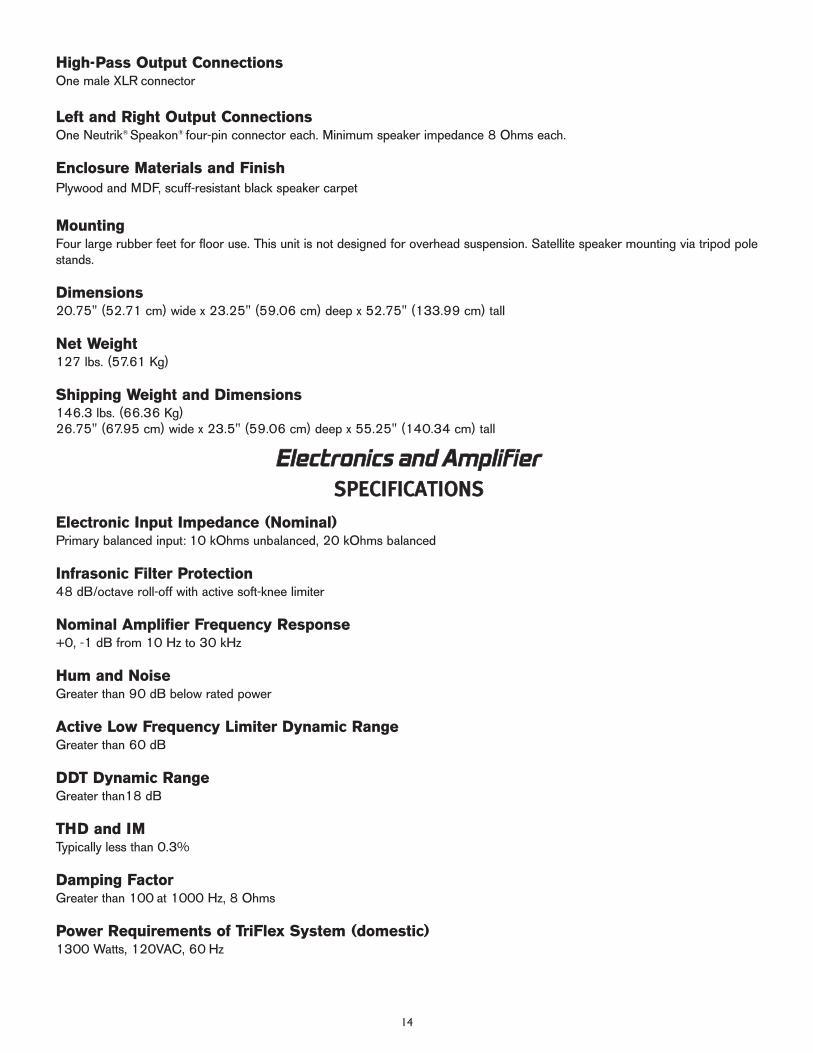
High-Pass Output ConnectionsOne male XLR connector
Left and Right Output ConnectionsOne Neutrik® Speakon® four-pin connector each. Minimum speaker impedance 8 Ohms each.
Enclosure Materials and FinishPlywood and MDF, scuff-resistant black speaker carpet
MountingFour large rubber feet for floor use. This unit is not designed for overhead suspension. Satellite speaker mounting via tripod polestands.
Dimensions20.75" (52.71 cm) wide x 23.25" (59.06 cm) deep x 52.75" (133.99 cm) tall
Net Weight127 lbs. (57.61 Kg)
Shipping Weight and Dimensions146.3 lbs. (66.36 Kg)26.75" (67.95 cm) wide x 23.5" (59.06 cm) deep x 55.25" (140.34 cm) tall
Electronic Input Impedance (Nominal)Primary balanced input: 10 kOhms unbalanced, 20 kOhms balanced
Infrasonic Filter Protection48 dB/octave roll-off with active soft-knee limiter
Nominal Amplifier Frequency Response+0, -1 dB from 10 Hz to 30 kHz
Hum and NoiseGreater than 90 dB below rated power
Active Low Frequency Limiter Dynamic RangeGreater than 60 dB
DDT Dynamic RangeGreater than18 dB
THD and IMTypically less than 0.3%
Damping FactorGreater than 100 at 1000 Hz, 8 Ohms
Power Requirements of TriFlex System (domestic)1300 Watts, 120VAC, 60 Hz
EElleeccttrroonniiccss aanndd AAmmpplliiffiieerrSSPPEECCIIFFIICCAATTIIOONNSS
15
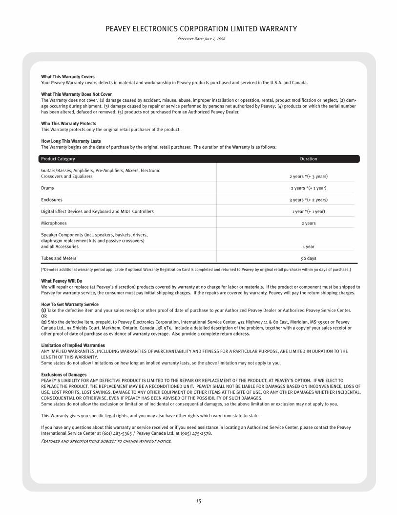
PEAVEY ELECTRONICS CORPORATION LIMITED WARRANTYEffective Date: July 1, 1998
WWhhaatt TThhiiss WWaarrrraannttyy CCoovveerrssYour Peavey Warranty covers defects in material and workmanship in Peavey products purchased and serviced in the U.S.A. and Canada.
WWhhaatt TThhiiss WWaarrrraannttyy DDooeess NNoott CCoovveerrThe Warranty does not cover: (1) damage caused by accident, misuse, abuse, improper installation or operation, rental, product modification or neglect; (2) dam-age occurring during shipment; (3) damage caused by repair or service performed by persons not authorized by Peavey; (4) products on which the serial numberhas been altered, defaced or removed; (5) products not purchased from an Authorized Peavey Dealer.
WWhhoo TThhiiss WWaarrrraannttyy PPrrootteeccttssThis Warranty protects only the original retail purchaser of the product.
HHooww LLoonngg TThhiiss WWaarrrraannttyy LLaassttssThe Warranty begins on the date of purchase by the original retail purchaser. The duration of the Warranty is as follows:
Product Category Duration
Guitars/Basses, Amplifiers, Pre-Amplifiers, Mixers, Electronic Crossovers and Equalizers 2 years *(+ 3 years)
Drums 2 years *(+ 1 year)
Enclosures 3 years *(+ 2 years)
Digital Effect Devices and Keyboard and MIDI Controllers 1 year *(+ 1 year)
Microphones 2 years
Speaker Components (incl. speakers, baskets, drivers, diaphragm replacement kits and passive crossovers) and all Accessories 1 year
Tubes and Meters 90 days
[*Denotes additional warranty period applicable if optional Warranty Registration Card is completed and returned to Peavey by original retail purchaser within 90 days of purchase.]
WWhhaatt PPeeaavveeyy WWiillll DDooWe will repair or replace (at Peavey's discretion) products covered by warranty at no charge for labor or materials. If the product or component must be shipped toPeavey for warranty service, the consumer must pay initial shipping charges. If the repairs are covered by warranty, Peavey will pay the return shipping charges.
HHooww TToo GGeett WWaarrrraannttyy SSeerrvviiccee((11)) Take the defective item and your sales receipt or other proof of date of purchase to your Authorized Peavey Dealer or Authorized Peavey Service Center. OR((22)) Ship the defective item, prepaid, to Peavey Electronics Corporation, International Service Center, 412 Highway 11 & 80 East, Meridian, MS 39301 or PeaveyCanada Ltd., 95 Shields Court, Markham, Ontario, Canada L3R 9T5. Include a detailed description of the problem, together with a copy of your sales receipt orother proof of date of purchase as evidence of warranty coverage. Also provide a complete return address.
LLiimmiittaattiioonn ooff IImmpplliieedd WWaarrrraannttiieessANY IMPLIED WARRANTIES, INCLUDING WARRANTIES OF MERCHANTABILITY AND FITNESS FOR A PARTICULAR PURPOSE, ARE LIMITED IN DURATION TO THELENGTH OF THIS WARRANTY. Some states do not allow limitations on how long an implied warranty lasts, so the above limitation may not apply to you.
EExxcclluussiioonnss ooff DDaammaaggeessPEAVEY'S LIABILITY FOR ANY DEFECTIVE PRODUCT IS LIMITED TO THE REPAIR OR REPLACEMENT OF THE PRODUCT, AT PEAVEY'S OPTION. IF WE ELECT TOREPLACE THE PRODUCT, THE REPLACEMENT MAY BE A RECONDITIONED UNIT. PEAVEY SHALL NOT BE LIABLE FOR DAMAGES BASED ON INCONVENIENCE, LOSS OFUSE, LOST PROFITS, LOST SAVINGS, DAMAGE TO ANY OTHER EQUIPMENT OR OTHER ITEMS AT THE SITE OF USE, OR ANY OTHER DAMAGES WHETHER INCIDENTAL,CONSEQUENTIAL OR OTHERWISE, EVEN IF PEAVEY HAS BEEN ADVISED OF THE POSSIBILITY OF SUCH DAMAGES.Some states do not allow the exclusion or limitation of incidental or consequential damages, so the above limitation or exclusion may not apply to you.
This Warranty gives you specific legal rights, and you may also have other rights which vary from state to state.
If you have any questions about this warranty or service received or if you need assistance in locating an Authorized Service Center, please contact the PeaveyInternational Service Center at (601) 483-5365 / Peavey Canada Ltd. at (905) 475-2578.
Features and specifications subject to change without notice.

Features and specifications subject to change without notice.
Peavey Electronics Corporation • 711 A Street • Meridian • MS • 39301
(601) 483-5365 • FAX (601) 486-1278 • www.peavey.com
80302145
©2004 Printed in the U.S.A. 9/04


